
Lite NVR4232-4KS2 - Video recorder Dahua Technology - Free user manual and instructions
Find the device manual for free Lite NVR4232-4KS2 Dahua Technology in PDF.


User questions about Lite NVR4232-4KS2 Dahua Technology
0 question about this device. Answer the ones you know or ask your own.
Ask a new question about this device
Download the instructions for your Video recorder in PDF format for free! Find your manual Lite NVR4232-4KS2 - Dahua Technology and take your electronic device back in hand. On this page are published all the documents necessary for the use of your device. Lite NVR4232-4KS2 by Dahua Technology.
USER MANUAL Lite NVR4232-4KS2 Dahua Technology
Network Video Recorder
User's Manual
V4.4.6
ZHEJIANG DAHUA VISION TECHNOLOGY CO., LTD.
General
This manual introduces the functions and operations of the XXX device (hereinafter referred to as "the Device").
Safety Instructions
The following categorized signal words with defined meaning might appear in the Manual.
| Signal Words | Meaning |
 DANGER DANGER | Indicates a high potential hazard which, if not avoided, will result in death or serious injury. |
 WARNING WARNING | Indicates a medium or low potential hazard which, if not avoided, could result in slight or moderate injury. |
 CAUTION CAUTION | Indicates a potential risk which, if not avoided, could result i property damage, data loss, lower performance, or unpredictable result. |
 PS PS | Provides methods to help you solve a problem or save you time. |
 TE TE | Provides additional information as the emphasis and supplement to the text. |
Revision History
| Version | Revision Content | Release Time |
| V4.4.6 | New UI interfaces and menu tree.New AI functions. | July 2019 |
| V4.4.5 | Deletes specifications | June 2019 |
| V4.4.4 | Add models: Cooper 1U (S3), Cooper 1U (S3) with 4 PoE Ports, Compact 1U (S3) with 8 PoE Ports Series. | August 2018 |
| V4.4.3 | Add Compact 1U 4K(S2) with Wireless and Smart 1U 4K(S2) with Wireless.Add Wi-Fi AP and Repeater functions.4K 1.5U (S2) with 24 PoE ports: Add altitude 5,000 meters. | July 2018 |
| V4.4.2 | Add GDPR information.Add FCC information.Update HDD installation. | June 2018 |
| V4.3.2 | Add Privacy Protection Notice and update About the Manual. | May 2018 |
| V4.3.1 | Add new models and update relevant information. | April 28, 2018 |
| V4.3.0 | Delete old models and add new models.Update relevant information. | October 12, 2017 |
| V4.2.0 | Add models. | September 21, 2017 |
| V4.1.0 | Update POS.Modify pictures with QR code and SN. | September 6, 2017 |
| V4.0.0 | Add cloud update module.Baseline switch and update screen interfaces. | August 15, 2017 |
| V3.0.0 | Add new modules.Baseline switch and update screen interfaces.Add new models. | May 10, 2016 |
| V1.0.0 | First Release. | - |
Privacy Protection Notice
Features II
As the device user or data controller, you might collect personal data of others such as face, fingerprints, car plate number, Email address, phone number, GPS and so on. You need to be in compliance with the local privacy protection laws and regulations to protect the legitimate rights and interests of other people by implementing measures include but not limited to: Providing clear and visible identification to inform data subject the existence of surveillance area and providing related contact.
About the Manual
- The manual is for reference only. If there is inconsistency between the manual and the actual product, the actual product shall prevail.
- We are not liable for any loss caused by the operations that do not comply with the manual.
- The manual would be updated according to the latest laws and regulations of related regions. For detailed information, see the paper manual, CD-ROM, QR code or our official website. If there is inconsistency between paper manual and the electronic version, the electronic version shall prevail.
- All the designs and software are subject to change without prior written notice. The product updates might cause some differences between the actual product and the manual. Please contact the customer service for the latest program and supplementary documentation.
- There still might be deviation in technical data, functions and operations description, or errors in print. If there is any doubt or dispute, please refer to our final explanation.
- Upgrade the reader software or try other mainstream reader software if the manual (in PDF format) cannot be opened.
- All trademarks, registered trademarks and the company names in the manual are the properties of their respective owners.
- Please visit our website, contact the supplier or customer service if there is any problem occurred when using the device.
- If there is any uncertainty or controversy, please refer to our final explanation.
The following description is the correct application method of the device. Read the manual carefully before use to prevent danger and property loss. Strictly conform to the manual during application and keep it properly after reading.
Operating Requirement
• Install the PoE front-end device indoors.
- The device does not support wall mount.
- Do not place and install the device in an area exposed to direct sunlight or near heat generating device.
- Do not install the device in a humid, dusty or fuliginous area.
- Keep its horizontal installation, or install it at stable places, and prevent it from falling.
- Do not drip or splash liquids onto the device; do not put on the device anything filled with liquids, in order to prevent liquids from flowing into the device.
- Install the device at well-ventilated places; do not block its ventilation opening.
- Use the device only within rated input and output range.
- Do not dismantle the device arbitrarily.
- Transport, use and store the device within allowed humidity and temperature range.
Power Requirement
- Make sure to use the designated battery type. Otherwise there may be explosion risk.
- Make sure to use batteries according to requirements. Otherwise, it may result in fire, explosion or burning risks of batteries!
- To replace batteries, only the same type of batteries can be used.
- Make sure to dispose the exhausted batteries according to the instructions.
- The product shall use electric wires (power wires) recommended by this area, which shall be used within its rated specification.
-
Make sure to use standard power adapter matched with this device. Otherwise, the user shall undertake resulting personnel injuries or device damages.
-
Use power supply that meets SELV (safety extra low voltage) requirements, and supply power with rated voltage that conforms to Limited Power Source in IEC60950-1. For specific power supply requirements, please refer to device labels.
- Products with category I structure shall be connected to grid power output socket, which is equipped with protective grounding.
- Appliance coupler is a disconnecting device. During normal use, please keep an angle that facilitates operation.
Foreword....I
Important Safeguards and Warnings....IV
Table of Contents......VI
1 Features....1
1.1 Overview....1
1.2 Features....1
2 Front Panel and Rear Panel....3
2.1 Front Panel....3
2.1.1 NVR41/41-P/41-W/21-S2/21-P-S2/21-8P-S2/41-4KS2/41-P-4KS2/41-8P-4KS2/21-4KS2/21-P-4KS2/21-8P-4KS2 Series....3
2.1.2 NVR41H/41H-P/41H-8P Series 3
2.1.3 NVR41HS-W-S2 Series....4
2.1.4 NVR41-8P Series 5
2.1.5 NVR42/42-P/42-8P Series 5
2.1.6 NVR21HS-S2/21HS-P-S2/21HS-8P-S2/41HS-4KS2/41HS-P-4KS2/41HS-8P-4KS2/21HS-4KS2/21HS-P-4KS2/21HS-8P-4KS2 Series....7
2.1.7 NVR/22-S2/22-P-S2/22-8P-S2/42-16P/42N/52-4KS2/52-8P-4KS2/52-16P-4KS2/42-4KS2/4 2-P-4KS2/42-8P-4KS2/42-16P-4KS2/5224-24P-4KS2/54-4KS2/54-16P-4KS2/44-4KS2/44-16P-4KS 2/5424-24P-4KS2/58-4KS2/S258-16P-4KS2/48-4KS2/48-16P-4KS2/22-4KS2/22-P-4KS2/22-8P-4K S2/52-8P-4KS2E/52-16P-4KS2E/54-16P-4KS2E/58-16P-4KS2E Series....8
2.1.8 NVR44/44-8P/44-16P Series....9
2.1.9 NVR48/48-16P Series 11
2.1.10 NVR42V-8P Series....13
2.1.11 NVR21-W-4KS2 Series 14
2.1.12 NVR21HS-W-4KS2 Series....15
2.2 Rear Panel 16
2.2.1 NVR41/41-P/41-8P/41-W Series 16
2.2.2 NVR21-S2/21-P-S2/21-8P-S2/21-4KS2/21-P-4KS2/21-8P-4KS2 Series....18
2.2.3 NVR41H/41H-P/41H-8P Series....19
2.2.4 NVR21HS-S2/21HS-P-S2/21HS-8P-S2/21HS-4KS2/21HS-P-4KS2/21HS-8P-4KS2 Series 20
2.2.5 NVR41HS-W-S2 Series....22
2.2.6 NVR22-S2/22-P-S2/22-8P-S2/22-4KS2/22-P-4KS2/22-8P-4KS2 Series....23
2.2.7 NVR42/42N/42-P/42-8P/42-16P Series....24
2.2.8 NVR52-4KS2/52-8P-4KS2/52-16P-4KS2/5224-24P-4KS2/52-8P-4KS2E/52-16P-4KS2E
Series 27
2.2.9 NVR44/44-8P/44-16P Series....29
2.2.10 NVR54-4KS2/58-4KS2/54-16P-4KS2/58-16P-4KS2/5424-24P-4KS2/5816P-4KS2E Series 31
2.2.11 NVR48/48-16P Series 34
2.2.12 NVR42V-8P Series....36
2.2.13 NVR41-4KS2/41-P-4KS2/41-8P-4KS2 37
2.2.14 NVR41HS-4KS2/41HS-P-4KS2/41HS-8P-4KS2....39
2.2.15 NVR42-4KS2/42-P-4KS2/42-8P-4KS2/42-16P-4KS2 40
2.2.16 NVR44-4KS2/44-16P-4KS2....43
2.2.17 NVR48-4KS2/48-16P-4KS2 Series 45
2.2.18 NVR21-W-4KS2 Series 46
2.2.19 NVR21HS-W-4KS2 Series....47
2.3 Alarm Connection....48
2.3.1 Alarm Port....48
2.3.2 Alarm input port 49
2.3.3 Alarm input and output port....50
2.3.4 Alarm relay specifications ....50
2.4 Bidirectional talk 51
2.4.1 Device-end to PC-end 51
2.4.2 PC-end to the device-end 51
2.5 Mouse Operation....52
2.6 Remote Control 53
3 Device Installation....55
3.1 Device Installation Diagrams....55
3.2 Check Unpacked NVR....55
3.3 About Front Panel and Rear Panel....56
3.4 HDD Installation....56
3.4.1
KS2/21-P-4KS2/21-8P-4KS2/21-W-4KS2 Series 56
3.4.2
NVR41H/41H-P/41H-8P/21HS-S2/21HS-P-S2/21HS-8P-S2/41HS-W-S2/41HS-4KS2/41HS
-P-4KS2/41HS-8P-4KS2/21HS-4KS2/21HS-P-4KS2/21HS-8P-4KS2/21HS-W-4KS2 Series....57
3.4.3
NVR42/42N/42-P/42-8P/42-16P/42-4K/42-8P-4K/52-4KS2/52-8P-4KS2/52-16P-4KS2/22-S
2/22-P-S2/22-8P-S2/42-4KS2/42-P-4KS2/42-8P-4KS2/42-16P-4KS2/5224-24P-4KS2/22-4KS2/22-
P-4KS2/22-8P-4KS2/52-8P-4KS2E/52-16P-4KS2E Series 57
3.4.4
NVR44/44-8P/44-16P/54-4KS2/54-16P-4KS2/44-4KS2/44-16P-4KS2/5424-24P-4KS2/54-1
6P-4KS2E Series 58
3.4.5 NVR48/48-16P/58-4KS2/58-16P-4KS2/48-4KS2/48-16P-4KS2/52-16P-4KS2E Series.....58
3.4.6 NVR42V-8P Series 59
3.5 CD-ROM Installation....60
3.6 Connection Sample....61
3.6.1
3.6.5 NVR22-S2/22-P-S2/22-8P-S2/22-4KS2/22-P-4KS2/22-8P-4KS2 Series....65
3.6.6 NVR42N Series 66
3.6.7
NVR42/42-P/42-8P/42-16P/52-4KS2/52-8P-4KS2/52-16P-4KS2/5224-24P-4KS2/52-8P-4K
S2E/52-16P-4KS2E Series....66
3.6.8 NVR42-8P-4K/42-4KS2/42-P-4KS2/42-8P-4KS2/42-16P-4KS2 Series....67
3.6.9
NVR54-4KS2/54-16P-4KS2/58-4KS2/58-16P-4KS2/5424-24P-4KS2/54-16P-4KS2E/5816P
-4KS2E Series 68
3.6.10 NVR44/44-8P/44-16P/44-4KS2/44-16P-4KS2 Series 68
3.6.11 NVR48/48-16P/48-4KS2/48-16P-4KS2 Series....69
3.6.12 NVR42V-8P Series 70
4 Local Basic Operation 71
4.1 Getting Started....71
4.1.1 Boot up....71
4.1.2 Device Initialization 71
4.1.3 Reset Password....75
4.1.4 Quick Settings....81
4.2 Camera....108
4.2.1 Connection 108
4.2.2 Remote Device Initialization 112
4.2.3 Short-Cut Menu to Register Camera....116
4.2.4 Image 116
4.2.5 Encode....119
4.2.6 Channel Name 123
4.2.7 Remote Upgrade 124
4.2.8 Remote Device Info....125
4.3 Live View 126
4.3.1 Preview 126
4.3.2 Navigation bar....127
4.3.3 Preview Control Interface....130
4.3.4 Sequence....135
4.3.5 Fisheye (Optional)....137
4.3.6 Test Temperature....140
4.3.7 AI Preview Mode 141
4.4 PTZ....143
4.4.1 PTZ Settings....144
4.4.2 PTZ Control....145
4.4.3 Configuring PTZ Functions....148
4.4.4 Calling PTZ Functions 150
4.5 Record File 151
4.6 Playback and Search....151
4.6.1 Instant Playback 151
4.6.2 Search Interface 151
4.6.3 Smart Search Playback....157
4.6.4 Mark Playback 158
4.6.5 Playback Image....159
4.6.6 Splice Playback....159
4.6.7 File List....160
4.6.8 Other Aux Functions....162
4.7 AI....162
4.7.1 AI Search....162
4.7.2 Parameters....176
4.7.3 Database 216
4.8 Event Manager 223
4.8.1 Alarm Info 223
4.8.2 Alarm Status....224
4.8.3 Alarm Input 225
4.8.4 Alarm Control 228
4.8.5 Video Detection 229
4.8.6 Audio Detect....237
4.8.7 Thermal Alarm 240
4.8.8 Abnormality....243
4.9 POS....248
4.9.1 Search....248
4.9.2 Settings....249
4.10 Operation and Maintenance 252
4.10.1 Log....252
4.10.2 System 254
4.10.3 Network....257
4.10.4 Maintenance and Management....260
4.11 File Backup....267
4.12 Network....268
4.12.1 TCP/IP 268
4.12.2 Port 270
4.12.3 PPPoE....272
4.12.4 DDNS 273
4.12.5 UPnP 275
4.12.6 Email....277
4.12.7 SNMP 278
4.12.8 Multicast....280
4.12.9 Alarm Centre....281
4.12.10 Register 282
4.12.11 P2P 283
4.12.12 802.1X....286
4.13 Storage 287
4.13.1 Basic....288
4.13.2 Schedule....289
4.13.3 HDD....289
4.13.4 Record Control....289
4.13.5 Advance (HDD Group)....290
4.13.6 HDD Detect 290
4.13.7 RAID....293
4.13.8 Record Estimate....298
4.13.9 FTP 300
4.14 System....302
4.14.1 General 302
4.14.2 RS232 302
4.14.3 Security 304
4.15 Account....307
4.15.1 User 307
4.15.2 Group 310
4.15.3 Reset Password....311
4.15.4 ONVIF User....312
4.16 Output and Display....314
4.16.1 Display 314
4.16.2 Tour....315
4.16.3 Customized Display 317
4.17 Audio 319
4.17.1 File Manage....319
4.17.2 Schedule....321
4.17.3 Broadcast....322
4.18 USB Device Auto Pop-up....324
4.19 Shutdown....324
5 Web Operation....328
5.1 Network Connection....328
5.2 Web Login 328
5.3 Reset Password 329
5.4 Web Main Menu 331
6 Glossary....334
7 FAQ....335
Appendix 1 Cybersecurity Recommendations....340
Appendix 2 HDD Capacity Calculation....343
Appendix 3 Compatible Network Camera List....344
1.1 Overview
This series NVR is a high performance network video recorder. This series product support local preview, multiple-window display, recorded file local storage, remote control and mouse shortcut menu operation, and remote management and control function.
This series product supports center storage, front-end storage and client-end storage. The monitor zone in the front-end can be set in anywhere. Working with other front-end devices such as IPC, NVS, this series product can establish a strong surveillance network via the CMS. In the network system, there is only one network cable from the monitor center to the monitor zone in the whole network. There is no audio/video cable from the monitor center to the monitor zone. The whole project is featuring of simple connection, low-cost, low maintenance work.
This series NVR can be widely used in many areas such as public security, water conservancy, transportation and education.
1.2 Features
| Cloud Upgrade | For the NVR connected with the Internet, it supports online upgrade to update applications. |
| Real-time Surveillance | VGA, HDMI port. Connect to monitor to realize real-time surveillance. Some series support TV/VGA/HDMI output at the same time.Short-cut menu when preview.Support popular PTZ decoder control protocols. Support preset, tour and pattern. |
| Playback | Support each channel real-time record independently, and at the same time it can support search, forward play, network monitor, record search, download and etc.Support various playback modes: slow play, fast play, backward play and frame by frame play.Support time title overlay so that you can view event accurate occurred timeSupport specified zone enlargement. |
| User Management | Each group has different management powers that can be edited freely. Every user belongs to an exclusive group. |
| Storage | Via corresponding setup (such as alarm setup and schedule setup), you can backup related audio/video data in the network video recorder.Support Web record and record local video and storage the file in the client end. |
| Alarm | Respond to external alarm simultaneously (within 200MS), based on user's pre-defined relay setup, system can process the alarm inputcorrectly and prompt user by screen and voice (support pre-recorded audio).Support central alarm server setup, so that alarm information can remotely notify user automatically. Alarm input can be derived from various connected peripheral devices.Alert you via email/sms. |
| Network Monitor | Through network, sending audio/video data compressed by IPC or NVS to client-ends, then the data will be decompressed and display.Support max 128 connections at the same time.Transmit audio/video data by HTTP, TCP, UDP, MULTICAST, RTP/RTCP and etc.Transmit some alarm data or alarm info by SNMP.Support WEB access in WAN/LAN. |
| Window Split | Adopt the video compression and digital process to show several windows in one monitor. Support 1/4/8/9/16/ 25/36-window display when preview and 1/4/9/16-window display when playback. |
| Record | Support normal/motion detect/alarm record function. Save the recorded files in the HDD, USB device, client-end PC, or network storage server. You can search or playback the saved files at the local-end or via the Web/USB device. |
| Backup | Support network backup, USB2.0 record backup function, the recorded files can be saved in network storage server, peripheral USB2.0 device, burner and etc. |
| Network Management | Supervise NVR configuration and control power via Ethernet.Support management via WEB. |
| Peripheral Equipment Management | Support peripheral equipment management such as protocol setup and port connection.Support transparent data transmission such as RS232 (RS-422), RS485 (RS-485). |
| Auxiliary | Support switch between NTSC and PAL.Support real-time system resources information and running statistics display.Support log file.Local GUI output. Shortcut menu operation via mouse.IR control function (For some series product only). Shortcut menu operation via remote control.Play the video/audio from the network camera or NVS remotely. |

NOTE
The following front panel and rear panel figures are for reference only. The actual product shall prevail.
2.1 Front Panel
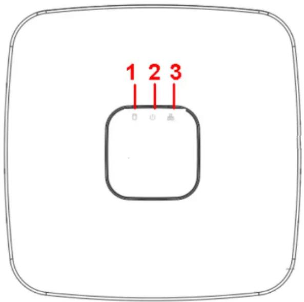
2.1.1 NVR41/41-P/41-W/21-S2/21-P-S2/21-8P-S2/41-4KS2/41-P-4KS2/41-8P-4KS2/21-4KS2/21-P-4KS2/21-8P-4KS2 Series
The front panel is shown as in Figure 2-1.
Figure 2-1
text_image
1 2 3Table 2-1
| SN | Name | Function |
| 1 | HDD status indicator light | The red light becomes on when HDD is abnormal. |
| 2 | Power indicator light | The red light becomes on when the power connection is OK. |
| 3 | Network status indicator light | The red light becomes on when the network connection is abnormal. |
2.1.2 NVR41H/41H-P/41H-8P Series
The front panel is shown as in Figure 2-2.
Figure 2-2

text_image
MTT PMR HDD G0Table 2-2
| Icon | Name | Function |
| NET | Network status indicator light | The red light becomes on when the network connection is abnormal. |
| PWR | Power indicator light | The red light becomes on when the power connection is OK. |
| HDD | HDD status indicator light | The red light becomes on when HDD is abnormal. |
| IR | Remote control receiver | It is to receive signal from the remote control. |
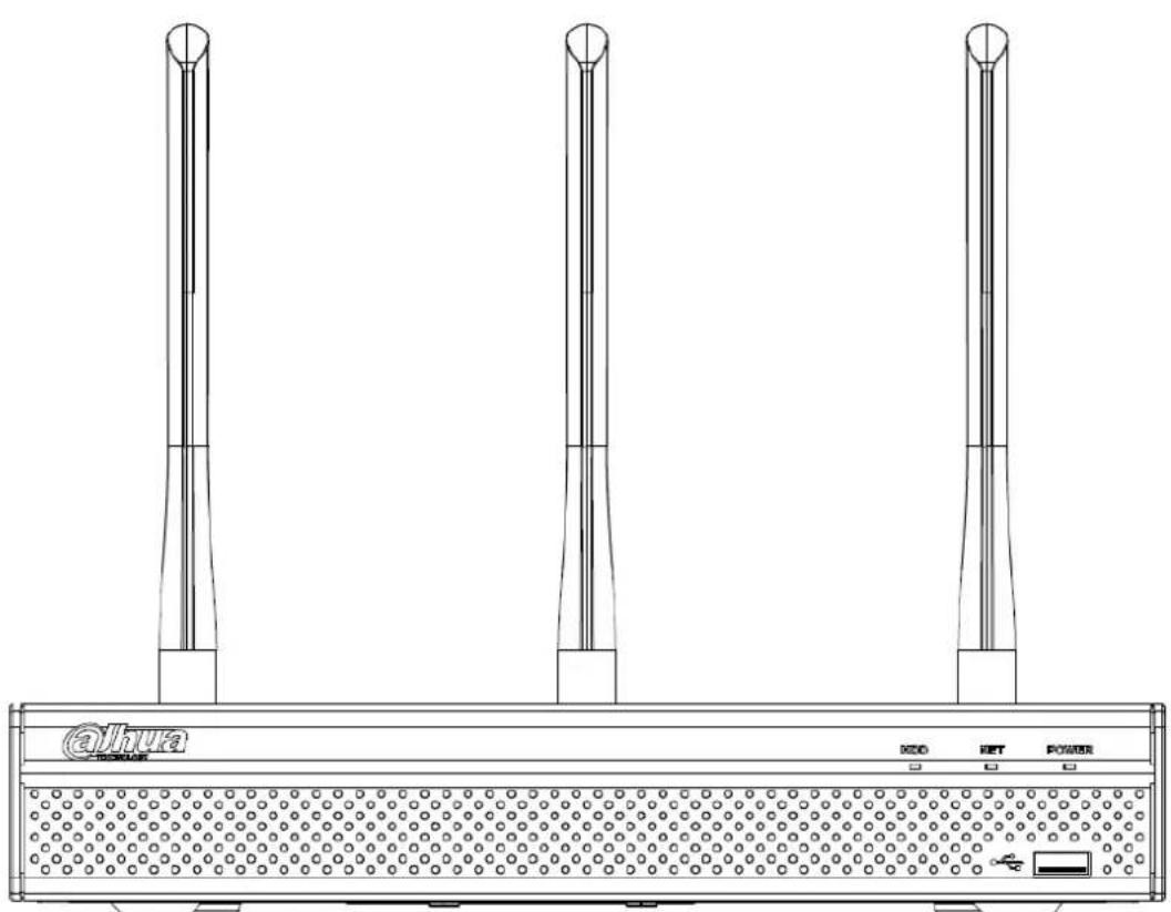
2.1.3 NVR41HS-W-S2 Series
The front panel is shown as below. See Figure 2-3.
Figure 2-3
natural_image
Line drawing of a power supply unit with three vertical towers and a base panel (no text or symbols on the main diagram)Table 2-3
| Icon | Name | Function |
| HDD | HDD status indicator light | The blue light is on when the HDD is malfunction. |
| NET | Network status indicator light | The blue light is on when the network connection is abnormal. |
| POWER | Power status indicator light | The blue light is on when the power connection is OK. |
| USB2.0 port | Connect to peripheral USB 2.0 storage device, mouse, burner and etc. |
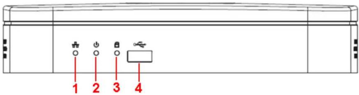
2.1.4 NVR41-8P Series
The front panel is shown as below. See Figure 2-4.
Figure 2-4
text_image
1 2 3 4Table 2-4
| SN | Name | Function |
| 1 | Network status indicator light | The red light becomes on when the network connection is abnormal. |
| 2 | Power indicator light | The red light becomes on when the power connection is OK. |
| 3 | HDD status indicator light | The red light becomes on when HDD is abnormal. |
| 4 | USB | USB port |
2.1.5 NVR42/42-P/42-8P Series
The front panel is shown as below. See Figure 2-5.
Figure 2-5

text_image
1 2 3 4 5 6 7 8 9 10 11 12 13 14 15 16 HDD NET +/-/0 >/-/0 >/-/0 >/-/7 D4/0 >/-/0 End Fm Shift Enter RetTable 2-5
| Icon | Name | Function |
| Power button | Power button, press this button for three seconds to boot up or shut down NVR. | |
| Shift | Shift | In textbox, click this button to switch between numeral, English(Small/Capitalized),donation and etc. |
| Up/1Down/4 | ▲\▼ | Activate current control, modify setup, and then move up and down. |
| Increase/decrease numeral. | ||
| Assistant function such as PTZ menu. | ||
| In text mode, input number 1/4 (English character G/H/I). | ||
| Left/2Right/3 | ◀\▶ | Shift current activated control. |
| When playback, click these buttons to control playback bar.In text mode, input number 2(English character A/B/C)/3(English character D/E/F). | ||
| ESC | ESC | Go to previous menu, or cancel current operation. |
| When playback, click it to restore real-time monitor mode. | ||
| Enter | ENTER | Confirm current operation. |
| Go to default button. | ||
| Go to menu. | ||
| Record | REC | Manually stop/start recording, working with direction keys.or numeral keys to select the recording channel. |
| Slow play/8 | ▸ | Multiple slow play speeds or normal playback.In text mode, input number 8 (English character T/U/V). |
| Assistant | Fn | One-window monitor mode, click this button to display assistant function: PTZ control and image color. |
| Backspace function: in numeral control or text control, press it for 1.5seconds to delete the previous character before the cursor. | ||
| In motion detection setup, working with Fn and direction keys to realize setup. | ||
| In text mode, click it to switch between numeral, English character(small/capitalized) and etc. | ||
| Fast play/7 | ▸ | Various fast speeds and normal playback.In text mode, input number 7 (English character P/Q/R/S). |
| Play previous/0 | |◀ | In playback mode, playback the previous video. In text mode, input number 0. |
| Reverse/Pause/6 | ||◀ | In normal playback or pause mode, click this button to reverse playback. In reverse playback, click this button to pause playback. In text mode, input number 6 (English character M/N/O). |
| Play Next/9 | ▶| | In playback mode, playback the next video. In menu setup, go to down ward of the dropdown list. In text mode, input number 9 (English character W/X/Y/Z). |
| Play/Pause /5 | ▶|| | In normal playback click this button to pause playback. In pause mode, click this button to resume playback. In text mode, input number 5(English character J/K/L). |
| USB port | To connect USB storage device, USB mouse. | |
| Network abnormal indicator light | Net | Network error occurs or there is no network connection, the light becomes red to alert you. |
| HDD abnormal indicator light | HDD | HDD error occurs or HDD capacity is below specified threshold value, the light becomes red to alert you. |
| Record light | 1-16 | System is recording or not. It becomes on when system is recording. |
| IR Receiver | IR | It is to receive the signal from the remote control. |
2.1.6 NVR21HS-S2/21HS-P-S2/21HS-8P-S2/41HS-4KS2/41HS-P-4KS2/41HS-8P-4KS2/21HS-4KS2/21HS-P-4KS2/21HS-8P-4KS2 Series
The front panel is shown as below. See Figure 2-6.
Figure 2-6

text_image
HDD NET POWERTable 2-6
| Icon | Name | Function |
| HDD | HDD status indicator light | The blue light is on when the HDD is malfunction. |
| NET | Network status indicator light | The blue light is on when the network connection is abnormal. |
| POWER | Power status indicator light | The blue light is on when the power connection is OK. |
| USB port | Connect to peripheral USB storage device, mouse and etc. |
2.1.7 NVR/22-S2/22-P-S2/22-8P-S2/42-16P/42N/52-4KS2/52-8P-4KS2/52-16P-4KS2/42-4KS2/42-P-4KS2/42-8P-4KS2/42-16P-4KS2/5224-24P-4KS2/54-4KS2/54-16P-4KS2/44-4KS2/44-16P-4KS2/5424-24P-4KS2/58-4KS2/S258-16P-4KS2/48-4KS2/48-16P-4KS2/22-4KS2/22-P-4KS2/22-8P-4KS2/52-8P-4KS2E/52-16P-4KS2E/54-16P-4KS2E/58-16P-4KS2E Series
The
NVR22-S2/NVR22-P-S2/22-8P-S2/42-16P/42N/52-4KS2/52-8P-4KS2/52-16P-4KS2/42-4KS2/42-P-4KS2/42-8P-4KS2/42-16P-4KS2/5224-24P-4KS2/22-4KS2/22-P-4KS2/22-8P-4KS2/52-8P-4KS2E/52-16P-4KS2E series front panel is shown as in Figure 2-7.
Figure 2-7

text_image
STATUS HDD NET POWERThe NVR54-4KS2/54-16P-4KS2/44-4KS2/44-16P-4KS2/5424-24P-4KS2/54-16P-4KS2E series front panel is shown as in Figure 2-8.
Figure 2-8

text_image
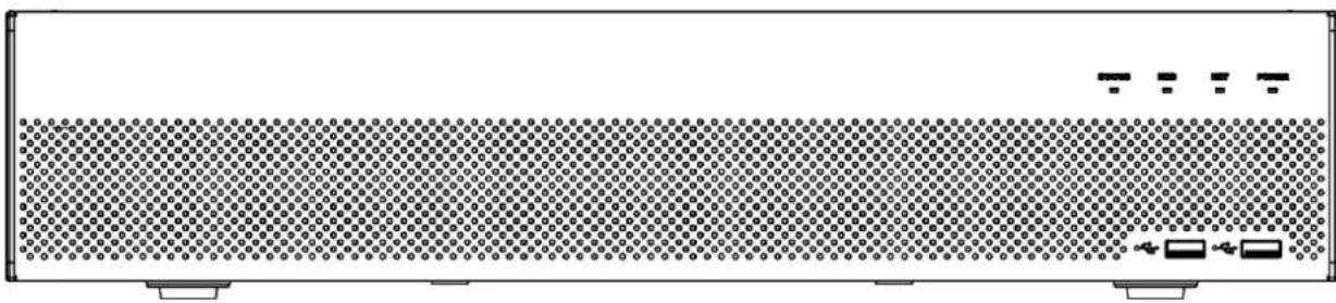
STATUS HDD NET POWER 00 00 00 00The NVR58-4KS2/58-16P-4KS2/48-4KS2/48-16P-4KS2/58-16P-4KS2E series front panel is shown as in Figure 2-9.
Figure 2-9
natural_image
Front view of a server rack with indicator lights and ports (no text or symbols visible)Table 2-7
| Icon | Name | Function |
| STATUS | Status indicator light | The blue light is on when the device is malfunction. |
| HDD | HDD status indicator light | The blue light is on when the HDD is malfunction. |
| NET | Network status indicator light | The blue light is on when the network connection is abnormal. |
| POWER | Power status indicator light | The blue light is on when the power connection is OK. |
| USB2.0 port | Connect to peripheral USB 2.0 storage device, mouse, burner and etc. |
2.1.8 NVR44/44-8P/44-16P Series
The front panel is shown as in Figure 2-10.
Figure 2-10

text_image
Enter Shift Esc Fn Rec OK OK/S OK/S OK/S OK/S OK/S OK/S OK/S OK/S OK/S OK/S OK/S OK/S OK/S OK/S OK/S OK/S OK/S OK/S OK/S OK/S OK/S OK/S OK/S OK/S OK/S OK/S OK/S OK/S OK/S OK/S OK/S OK/S OK/S OK/STable 2-8
| Icon | Name | Function |
| Power button | Power button, press this button for three seconds to boot up or shut down NVR. | |
| Shift | Shift | In textbox, click this button to switch between numeral, English(Small/Capitalized),donation and etc. |
| Up/1Down/4 | ▲\▼ | Activate current control, modify setup, and then move up and down. |
| Increase/decrease numeral. | ||
| Assistant function such as PTZ menu. | ||
| In text mode, input number 1/4 (English character G/H/I). | ||
| Left/2Right/3 | Shift current activated control. | |
| When playback, click these buttons to control playback bar.In text mode, input number 2(English character A/B/C)./3(English character D/E/F). | ||
| ESC | ESC | Go to previous menu, or cancel current operation.When playback, click it to restore real-time monitor mode. |
| Enter | ENTER | Confirm current operation. |
| Go to default button. | ||
| Go to menu. | ||
| Record | REC | Manually stop/start recording, working with direction keys.or numeral keys to select the recording channel. |
| Slow play/8 | ▶ | Multiple slow play speeds or normal playback.In text mode, input number 8 (English character T/U/V). |
| Assistant | Fn | One-window monitor mode, click this button to display assistant function: PTZ control and image color. |
| Backspace function: in numeral control or text control, press it for 1.5seconds to delete the previous character before the cursor. | ||
| In motion detection setup, working with Fn and direction keys to realize setup. | ||
| In text mode, click it to switch between numeral, English character(small/capitalized) and etc. | ||
| Fast play/7 | ▶ | Various fast speeds and normal playback.In text mode, input number 7 (English character P/Q/R/S). |
| Play previous/0 | |◀ | In playback mode, playback the previous videoIn text mode, input number 0. |
| Reverse/Pause/6 | ||◀ | In normal playback or pause mode, click this button to reverse playback.In reverse playback, click this button to pause playback.In text mode, input number 6 (English character M/N/O). |
| Play Next/9 | ▶| | In playback mode, playback the next video.In menu setup, go to down ward of the dropdown list.In text mode, input number 9 (English character W/X/Y/Z). |
| Play/Pause /5 | ▶|| | In normal playback click this button to pause playback.In pause mode, click this button to resume playback.In text mode, input number 5(English character J/K/L). |
| USB port | ○○ | To connect USB storage device, USB mouse. |
| Network abnormal indicator light | Net | Network error occurs or there is no network connection, the light becomes red to alert you. |
| HDD abnormal indicator light | HDD | HDD error occurs or HDD capacity is below specified threshold value, the light becomes red to alert you. |
| Record light | 1-16 | System is recording or not. It becomes on when system is recording. |
2.1.9 NVR48/48-16P Series
The Front panel is shown as follows. See Figure 2-11.
Figure 2-11
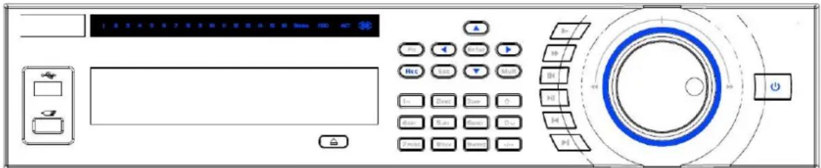
text_image
Control panel interface with labeled buttons and a circular dial indicatorTable 2-9
| Icon | Name | Function |
| Power button | Power button, press this button for three seconds to boot up or shut down NVR. | |
| Number button | 0-9 | Input Arabic number.Switch channel. |
| Input number more than 10 | -/-- | If you want to input a number more than 10, please click this button and then input. |
| Shift | ↑ | In textbox, click this button to switch between numeral, English(Small/Capitalized),donation and etc. |
| Enable or disable tour. | ||
| Up/Down | ▲\▼ | Activate current control, modify setup, and then move up and down. |
| Increase/decrease numeral. | ||
| Assistant function such as PTZ menu. | ||
| Left/Right | Shift current activated control, and then move left and right. | |
| When playback, click these buttons to control playback bar. | ||
| ESC | ESC | Go to previous menu, or cancel current operation. |
| When playback, click it to restore real-time monitor mode. | ||
| Enter | ENTER | Confirm current operation.Go to default button. |
| Go to menu. | ||
| Record | REC | Manually stop/start recording, working with direction keys or numeral keys to select the recording channel. |
| Slow play | ▸ | Multiple slow play speeds or normal playback. |
| Assistant | Fn | One-window monitor mode, click this button to display assistant function: PTZ control and image color. |
| Backspace function: in numeral control or text control, press it for 1.5seconds to delete the previous character before the cursor. | ||
| In motion detection setup, working with Fn and direction keys to realize setup. | ||
| In text mode, click it to switch between numeral, English character(small/capitalized) and etc. | ||
| In HDD management interface, you can click it to switch HDD record information and other information (Menu prompt) | ||
| Realize other special functions. | ||
| Fast play | ▸ | Various fast speeds and normal playback. |
| Play previous | |◄ | In playback mode, playback the previous video. |
| Reverse/Pause | II ◀ | In normal playback or pause mode, click this button to reverse playback.In reverse playback, click this button to pause playback. |
| Play Next | ►| | In playback mode, playback the next video.In menu setup, go to down ward of the dropdown list. |
| Play/Pause | ► II | In normal playback click this button to pause playback.In pause mode, click this button to resume playback. |
| Window switch | Mult | Click it to switch one-window/multiple-window. |
| Shuttle(outer ring) | In real-time monitor mode it works as left/right direction key.Playback mode, counter clockwise to forward and clock wise to backward. | |
| Jog(inner dial) | Up/down direction key.Playback mode, turn the inner dial to realized frame by frame playback. (Only applies to some special versions.) | |
| USB port | To connect USB storage device, USB mouse. | |
| Remote control indicator light | ACT | Remote control indicator light. |
| Status indicator light | Status | If there is Fn indicator light, current status indicator light is null. |
| Power indicator light | PWR | Power indicator light. |
| Channel indicator light | 1-32 | For 4/8/16-channel series product.The corresponding channel light becomes on when system is recording.For 32/64-channel series product:When the light flashes slowly, it means the corresponding channel of 1-16 channel is recording now (Such as channel 1).When the light flashes fast, it means the corresponding channel of 17-32 channel is recording now (Such as channel 17)When the light becomes on, It means the corresponding 2 channels are recoding now (Such as channel 1 and channel 17.).The channel indicator light here does not show the status of the 33-64-channel. |
| IR Receiver | IR | It is to receive the signal from the remote control. |
2.1.10 NVR42V-8P Series
The front panel is shown as below. See Figure 2-12.
Figure 2-12
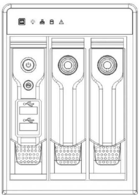
natural_image
Technical line drawing of a three-tiered industrial vessel or storage unit with control panels and indicator lights (no text or symbols)Table 2-10
| Name | Icon | Function |
| Power button | ➊ | Power button, press this button for three seconds to boot up or shut down NVR. |
| Assistant | Fn | One-window monitor mode, click this button to display assistant function: PTZ control and image color.Backspace function: in numeral control or text control, press it for 1.5 seconds to delete the previous character before the cursor.In motion detection setup, working with Fn and direction keys to realize setup.In text mode, click it to switch between numeral, English character (small/capitalized) and etc.In HDD management interface, you can click it to switch HDD record information and other information (Menu prompt)Realize other special functions. |
| USB2.0 port | To connect USB2.0 storage device, USB2.0 mouse, burner and etc. | |
| IR receive window | It is to receive the IR signal from the remote control. | |
| Power indicator light | Power indicator light. | |
| HDD abnormal indicator light | HDD error occurs or HDD capacity is below specified threshold value, the light becomes red to alert you. | |
| Network abnormal indicator light | Network error occurs or there is no network connection, the light becomes red to alert you. | |
| Alarm indicator light | The light becomes on when an alarm occurred. |
2.1.11 NVR21-W-4KS2 Series
The front panel is shown as below. See Figure 2-13.
Figure 2-13
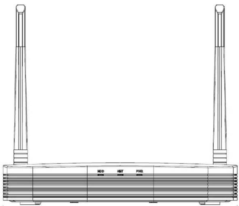
natural_image
Line drawing of a server rack with two towers and a central control panel (no text or symbols)Table 2-11
| Icon | Name | Function |
| HDD | HDD status indicator light | The blue light is on when the HDD is malfunction. |
| NET | Network status indicator light | The blue light is on when the network connection is abnormal. |
| PWR | Power status indicator light | The blue light is on when the power connection is OK. |
2.1.12 NVR21HS-W-4KS2 Series
The front panel is shown as below. See Figure 2-14.
Figure 2-14
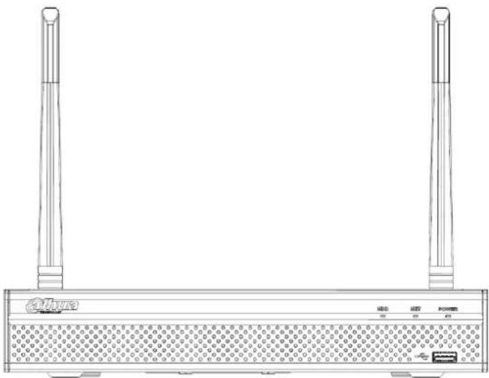
natural_image
Line drawing of a network device with two vertical towers and a central display board (no text or symbols)Table 2-12
| Icon | Name | Function |
| HDD | HDD status indicator light | The blue light is on when the HDD is malfunction. |
| NET | Network status indicator light | The blue light is on when the network connection is abnormal. |
| POWER | Power status indicator light | The blue light is on when the power connection is OK. |
| USB2.0 port | Connect to peripheral USB 2.0 storage device, mouse and etc. |
2.2 Rear Panel
2.2.1 NVR41/41-P/41-8P/41-W Series
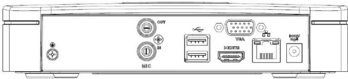
The NVR41 rear panel is shown as below. See Figure 2-15.
Figure 2-15
text_image
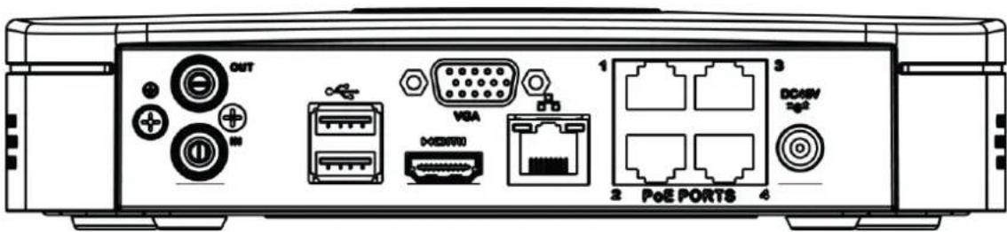
OUT HIC VAA HERTU BOXVThe NVR41-P rear panel is shown as below. See Figure 2-16.
Figure 2-16
text_image
OUT VGA D:01/01 PoE PORTS DCMIV 2g2The NVR41-8P rear panel is shown as below. See Figure 2-17.
Figure 2-17

text_image
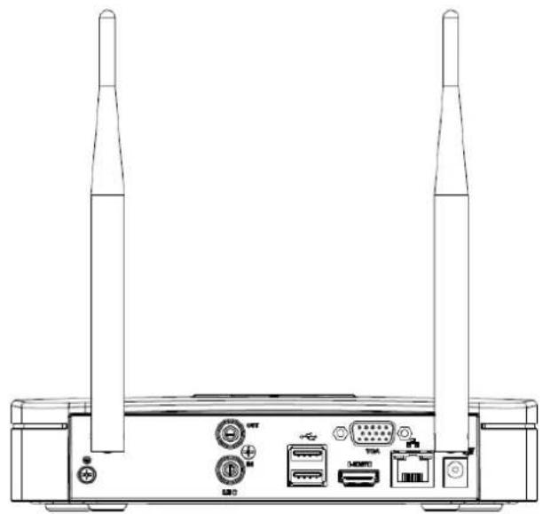
OUT VGA M1C P-DC2072 PoE PORTB 1357 2488 DC207 sgaThe NVR41-W rear panel is shown as below. See Figure 2-18.
Figure 2-18
natural_image
Line drawing of a wireless router with two towers and ports (no text or symbols)Table 2-13
| Port Name | Connection | Function |
 | USB2.0 port | USB2.0 port. Connect to mouse, USB storage device, USB burner and etc. |
 | Network port | 10M/100Mbps self-adaptive Ethernet port. Connect to the network cable. |
| HDMI | High Definition Media Interface | High definition audio and video signal output port. It transmits uncompressed high definition video and multiple-channel data to the HDMI port of the display device. HDMI version is 1.4. |
| VGA | VGA video output port | VGA video output port. Output analog video signal. It can connect to the monitor to view analog video. |
| 12 | GND | Ground end |
| DC 12V DC 48V 12 / 12 | Power input port | Power socket.For NVR41 series, input DC 12V/2A.For NVR41-P series, input DC 48V/1.5A.For NVR41-8P series, input DC 48V/2A. |
| MIC IN | Audio input port | Bidirectional talk input port. It is to receive the analog audio signal output from the devices such as microphone, pickup. |
| MIC OUT | Audio output port | Audio output port. It is to output the analog audio signal to the devices such as the sound box.Bidirectional talk output.Audio output on 1-window video monitor.Audio output on 1-window video playback. |
| PoE PORT | PoE port | Built-in switch. Support PoE function.For PoE series product, you can use this port to provide power to the network camera. |
| Wireless AP | Support wireless hotspot function. Use Wi-Fi to connect to the network camera when there is a hotspot.For 41-W series only. |
2.2.2 NVR21-S2/21-P-S2/21-8P-S2/21-4KS2/21-P-4KS2/21-8P-4KS2 Series
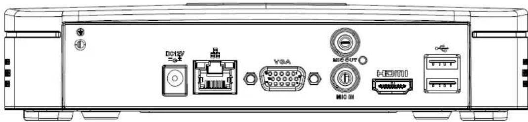
The NVR21-S2/21-4KS2 is shown as in Figure 2-19.
Figure 2-19
text_image
DCT2V =0.1 VGA MIC OUT MIC IN HDMIThe NVR21-P-S2/21-P-4KS2 is shown as in Figure 2-20.
Figure 2-20
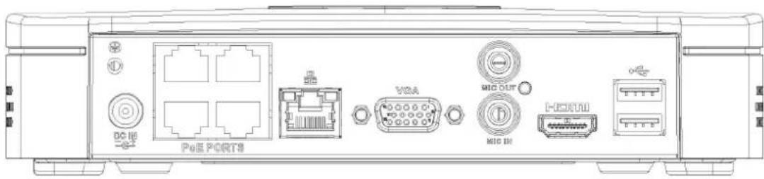
text_image
DC HD PUE PORTS V2A M1G OUT H000 M1G INThe NVR21-8P-S2/21-8P-4KS2 is shown as in Figure 2-21.
Figure 2-21
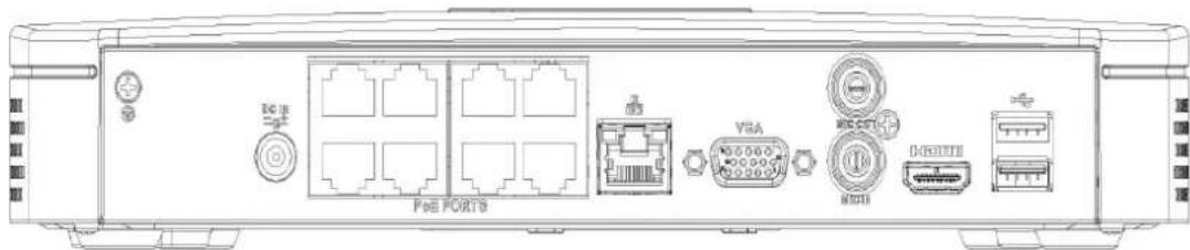
text_image
DC VBA MCCBT I/O I/OTable 2-14
| Port Name | Connection | Function |
| DC12V =G^2- | Power input portNetwork port | Power socketFor NVR21-S2/21-4KS2, input DC 12V/2A.For NVR21-P-S2/21-P-4KS2,input DC 48V/1.25A.For NVR21-8P-S2/21-8P-4KS2,input DC 48V/2A.10M/100Mbps self-adaptive Ethernet port. Connect to the network cable. |
| USB port | USB port. Connect to mouse, USB storage device and etc. | |
| HDMI | High Definition Media Interface | High definition audio and video signal output port. It transmits uncompressed high definition video and multiple-channel data to the HDMI port of the display device. HDMI version is 1.4. |
| VGA | VGA video output port | VGA video output port. Output analog video signal. It can connect to the monitor to view analog video. |
| MIC IN | Audio input port | Bidirectional talk input port. It is to receive the analog audio signal output from the devices such as microphone, pickup. |
| MIC OUT | Audio output port | Audio output port. It is to output the analog audio signal to the devices such as the sound box.• Bidirectional talk output.• Audio output on 1-window video monitor.• Audio output on 1-window video playback. |
| GND | Ground end | |
| PoE PORTS | PoE port | Built-in switch. Support PoE function.For PoE series product, you can use this port to provide power to the network camera. |
2.2.3 NVR41H/41H-P/41H-8P Series
The NVR41H rear panel is shown as in Figure 2-22.
Figure 2-22

text_image
OUT GPIO H10The NVR41H-P rear panel is shown as in Figure 2-23.
Figure 2-23

text_image
OUT VBA H-80000 Pall Port1 1 3 DCBOW 4 3 4The NVR41H-8P rear panel is shown as in Figure 2-24.
Figure 2-24

text_image
PGM PGE PORTS 1 3 5 7 DC48V 2 4 6 8Table 2-15
| Port Name | Connection | Function |
 | USB2.0 port | USB2.0 port. Connect to mouse, USB storage device, USB burner and etc. |
 | Network port | 10M/100Mbps self-adaptive Ethernet port. Connect to the network cable. |
| HDMI | High Definition Media Interface | High definition audio and video signal output port. It transmits uncompressed high definition video and multiple-channel data to the HDMI port of the display device. HDMI version is 1.4. |
| VGA | VGA video output port | VGA video output port. Output analog video signal. It can connect to the monitor to view analog video. |
 | GND | Ground end |
 DC 48V/ =G* DC 48V/ =G* | Power input port | Power socket.For NVR41 series, input DC 12V/2A.For NVR41H-P series, input DC 48V/1.5A.For NVR41H-8P series, input DC 48V/2A. |
| MIC IN | Audio input port | Bidirectional talk input port. It is to receive the analog audio signal output from the devices such as microphone, pickup. |
| MIC OUT | Audio output port | Audio output port. It is to output the analog audio signal to the devices such as the sound box.Bidirectional talk output.Audio output on 1-window video monitor.Audio output on 1-window video playback. |
| PoE PORT | PoE port | Built-in switch. Support PoE function. For PoE series product, you can use this port to provide power to the network camera. |
2.2.4 NVR21HS-S2/21HS-P-S2/21HS-8P-S2/21HS-4KS2/21HS-P-4KS2/21HS-8P-4KS2 Series
The NVR21HS-S2/21HS-4KS2 series rear panel is shown as below. See Figure 2-25.
Figure 2-25

text_image
DOCU VGA MDC OUT H-65010The NVR21HS-P-S2/21HS-P-4KS2 series rear panel is shown as below. See Figure 2-26.
Figure 2-26

text_image
PoE PORTS 1 2 DC UI Sag 2 4 VGA MGO OUT MIC IN MIC INThe NVR21HS-8P-S2/21HS-8P-4KS2 series rear panel is shown as below. See Figure 2-27.
Figure 2-27

text_image
PoE PORTS 1 3 3 7 DO IN 2 4 3 8 VBA MIC OUT MDC IN HSDU10 T111Table 2-16
| Port Name | Connection | Function |
 | Power input port | Power socket.For NVR21HS-S2/21HS-4KS2, input DC 12V/2A.For NVR21HS-P-S2/21HS-P-4KS2, input DC 48V/1.25A.For NVR21HS-8P-S2/21HS-8P-4KS2, input DC 48V/2A. |
 | Network port | 10M/100Mbps self-adaptive Ethernet port. Connect to the network cable. |
 | USB port | USB port. Connect to mouse, USB storage device and etc. |
| HDMI | High Definition Media Interface | High definition audio and video signal output port. It transmits uncompressed high definition video and multiple-channel data to the HDMI port of the display device. HDMI version is 1.4. |
| VGA | VGA video output port | VGA video output port. Output analog video signal. It can connect to the monitor to view analog video. |
| MIC IN | Audio input port | Bidirectional talk input port. It is to receive the analog audio signal output from the devices such as microphone, pickup. |
| MIC OUT | Audio output port | Audio output port. It is to output the analog audio signal to the devices such as the sound box.Bidirectional talk output.Audio output on 1-window video monitor.Audio output on 1-window video playback. |
| ⊥ | GND | Ground end |
| PoE PORTS | PoE port | Built-in switch. Support PoE function.For PoE series product, you can use this port to provide power to the network camera. |
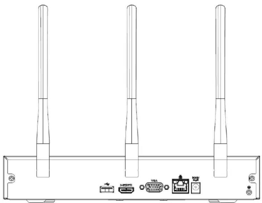
2.2.5 NVR41HS-W-S2 Series
The NVR41HS-W-S2 rear panel is shown as below. See Figure 2-28.
Figure 2-28
natural_image
Technical line drawing of a three-pin electronic device rear panel with ports and connectors (no text or symbols)Table 2-17
| Icon | Name | Function |
 | Power input socket. | Power socket. Input DC12V/2A. |
 | Network port | 10M/100Mbps self-adaptive Ethernet port. Connect to the network cable. |
 | USB2.0 port | USB2.0 port. Connect to mouse, USB storage device, and etc. |
| HDMI | High Definition Media Interface | High definition audio and video signal output port. It transmits uncompressed high definition video and multiple-channel data to the HDMI port of the display device. HDMI version is 1.4. |
| VGA | VGA video output port | VGA video output port. Output analog video signal. It can connect to the monitor to view analog video. |
| 12 | GND | Ground end |
| Wireless AP | Support wireless hotspot function. Use Wi-Fi to connect to the network camera when there is a hotspot. |
2.2.6 NVR22-S2/22-P-S2/22-8P-S2/22-4KS2/22-P-4KS2/22-8P-4KS2 Series
The NVR22-S2/22-4KS2 series rear panel is shown as below. See Figure 2-29.
Figure 2-29

text_image
ON OFF DCVSW MCP VDA MTC HOME +/-The NVR22-P-S2/22-P-4KS2 series rear panel is shown as below. See Figure 2-30.
Figure 2-30

text_image
PaaS PORTS VDA MICThe NVR22-8P-S2/22-8P-4KS2 series rear panel is shown as below. See Figure 2-31.
Figure 2-31

text_image
PN5 PORTS ON GTF VGA MTCTable 2-18
| Port Name | Connection | Function |
DC12V  | Power input portNetwork port | Power socket.For NVR22-S2/22-4KS2, input DC 12V/4A.For NVR22-P-S2/22-P-4KS2, input DC 48V/1.5A.For NVR22-8P-S2/22-8P-4KS2, input DC 53V 120W.10M/100Mbps self-adaptive Ethernet port. Connect to the network cable. |
 | USB port | USB port. Connect to mouse, USB storage device and etc. |
| HDMI | High Definition Media Interface | High definition audio and video signal output port. It transmits uncompressed high definition video and multiple-channel data to the HDMI port of the display device. HDMI version is 1.4. |
| VGA | VGA video output port | VGA video output port. Output analog video signal. It can connect to the monitor to view analog video. |
| MIC IN | Audio input port | Bidirectional talk input port. It is to receive the analog audio signal output from the devices such as microphone, pickup. |
| MIC OUT | Audio output port | Audio output port. It is to output the analog audio signal to the devices such as the sound box.Bidirectional talk output.Audio output on 1-window video monitor.Audio output on 1-window video playback. |
 | GND | Ground end |
| PoE PORTS | PoE port | Built-in switch. Support PoE function.For PoE series product, you can use this port to provide power to the network camera. |
2.2.7 NVR42/42N/42-P/42-8P/42-16P Series
The NVR42 series rear panel is shown as below. See Figure 2-32.
Figure 2-32

text_image
VGA RS232 HDMI DC12V ON OFFThe NVR42N series rear panel is shown as below. See Figure 2-33.
Figure 2-33

text_image
VGA R5232 HDMI DC12V ON OFFThe NVR42-P series rear panel is shown as below. See Figure 2-34.
Figure 2-34

text_image
PDS POINTS 1 3 DC48V 2 4 VGA MSI OUT RS232 HDMI 539 DC50V ON OFFThe NVR42-8P series rear panel is shown as below. See Figure 2-35.
Figure 2-35

text_image
Diagram of a network device rear panel with labeled ports, connectors, and internal components such as GPIO, VGA, RS232, and HOM.The NVR42-16P series rear panel is shown as below. See
Figure 2-36.
Figure 2-36

text_image
PeE PORTS 1 3 5 7 9 11 13 15 2 4 6 5 10 12 14 15 I/O port ↓ 1 2 ↓ I/O port ↓ 3 4 VGA RS13E MTC I/O port 55°C ⑪Table 2-19
| Name | Function | |
 | Power switch | Power on/off button. |
 | ||
 | Power input port | Input DC 12V/5A.For NVR42 series product only. |
 | Switch power port. Input DC 48//1.04A.For NVR42-P series product only. | |
 | Input AC 100~240V.For NVR42-8P/42-16P series product only. | |
| MIC IN | Audio input port | Bidirectional talk input port. It is to receive the analog audio signal output from the devices such as microphone, pickup. |
| MIC OUT | Audio output port | Audio output port. It is to output the analog audio signal to the devices such as the sound box.Bidirectional talk output.Audio output on 1-window video monitor.Audio output on 1-window video playback. |
| 1~4 | Alarm input port1~4 | There are two types; NO (normal open)/NC (normal close).When your alarm input device is using external power, please make sure the device and the NVR have the same ground. |
| 12 | GND | Alarm input ground port. |
| N1, N2 | Alarm output port1~2 | 2 groups of alarm output ports. (Group 1: port NO1~C1, Group 2: port NO2~C2). Output alarm signal to the alarm device. Please make sure there is power to the external alarm device.NO: Normal open alarm output port.C: Alarm output public end. |
| C1, C2 | ||
| A | RS-485 communication port | RS485_A port. It is the cable A. You can connect to the control devices such as speed dome PTZ. |
| B | RS485_B. It is the cable B. You can connect to the control devices such as speed dome PTZ. | |
| Network port | 10M/100M/1000Mbps self-adaptive Ethernet port. Connect to the network cable. | |
| USB2.0 port | USB2.0 port. Connect to mouse, USB storage device, USB burner and etc. | |
| RS-232 | RS-232 debug COM. | It is for general COM debug to configure IP address or transfer transparent COM data. |
| HDMI | High Definition Media Interface | High definition audio and video signal output port. It transmits uncompressed high definition video and multiple-channel data to the HDMI port of the display device. HDMI version is 1.4. |
| VGA | VGA video output port | VGA video output port. Output analog video signal. It can connect to the monitor to view analog video. |
| PoE PORTS | / | Built-in Switch. Support PoE.The 4 PoE series product supports total 48V 50W.The 8 PoE series product supports total 48V 120W.The 16 PoE series product supports total 120W. One PoE port max supports 15W. |
2.2.8 NVR52-4KS2/52-8P-4KS2/52-16P-4KS2/5224-24P-4KS2/52-8P-4KS2E/52-16P-4KS2E Series
The NVR52-4KS2 series rear panel is shown as below. See Figure 2-37.
Figure 2-37

natural_image
Back view of a computer chassis showing internal components like connectors, drive, and ports (no text or labels visible)The NVR52-8P-4KS2 series rear panel is shown as below. See Figure 2-38.
Figure 2-38

text_image
Diagram of a network device rear panel showing ports, connectors, and I/O ports with labels like 'VGA' and 'HDMI'The NVR52-16P-4KS2 series rear panel is shown as below. See Figure 2-39.
Figure 2-39

text_image
Pc-PORTS 1 3 5 7 9 11 13 16 2 4 6 8 10 12 14 16 VGA HDMI USB TCP F1The NVR5224-24P-4KS2 series rear panel is shown as below. See Figure 2-40.
Figure 2-40

natural_image
Front view of a network equipment rack with ports, connectors, and connectors (no visible text or labels)The NVR52-8P-4KS2E/52-16P-4KS2E series rear panel is shown as below. See Figure 2-41.

The following figure takes NVR52-16P-4KS2E series as an example. NVR52-8P-4KS2E series has 8 ePoE ports only.
Figure 2-41

text_image
PAS PORTS 1 3 5 7 9 11 13 15 2 4 6 8 10 12 14 16 HDMI VGA RS222 MIC HDMI 30%Table 2-20
| Icon | Port Name | Function |
| [SWRW] | Network port | 10M/100M/1000Mbps self-adaptive Ethernet port. Connect to the network cable. |
| HDMI | High Definition Media Interface | High definition audio and video signal output port. It transmits uncompressed high definition video and multiple-channel data to the HDMI port of the display device. HDMI version is 1.4. |
 | USB3.0 port | USB3.0 port. Connect to mouse, USB storage device, USB burner and etc. |
| RS-232 | RS-232 debug COM. | It is for general COM debug to configure IP address or transfer transparent COM data. |
| VGA | VGA video output port | VGA video output port. Output analog video signal. It can connect to the monitor to view analog video. |
| MIC IN | Audio input port | Bidirectional talk input port. It is to receive the analog audio signal output from the devices such as microphone, pickup. |
| MIC OUT | Audio output port | Audio output port. It is to output the analog audio signal to the devices such as the sound box.Bidirectional talk output.Audio output on 1-window video monitor.Audio output on 1-window video playback. |
| 1~8 | Alarm input port 1~8 | There are two groups. The first group is from port 1 to port 4; the second group is from port 5 to port 8. They are to receive the signal from the external alarm source. There are two types; NO (normal open)/NC (normal close).When your alarm input device is using external power, please make sure the device and the NVR have the same ground. |
| 12 | GND | Alarm input ground port. |
| NO1~NO3 | Alarm output port 1~3 | 3 groups of alarm output ports. (Group 1:port NO1~C1,Group 2:port NO2~C2,Group 3:port NO3~C3).Output alarm signal to the alarm device. Please make sure there is power to the external alarm device.NO: Normal open alarm output port.C:Alarm output public end. |
| C1~C3 | ||
| A | RS-485 communication | RS485_A port. It is the cable A. You can connect to the control devices such as speed dome PTZ. |
| B | port | RS485_B.It is the cable B. You can connect to the control devices such as speed dome PTZ. |
| DC12V | Power input port | Input DC 12V/4A. |
| Power switch | / | Power on/off button. |
| PoE PORTS | / | Built-in Switch. Support PoE or ePoE function.For ePoE series product, port 1 to port 8 are the ePoE ports. ePoE port supports 300 meters@100Mbps, 800 meters@10Mbps. Port 9 to port 16 are general PoE ports.The 8 PoE series product supports total 130W.The 16 PoE series product supports total 130W. |
2.2.9 NVR44/44-8P/44-16P Series
The NVR44 series rear panel is shown as below. See Figure 2-42.
Figure 2-42

text_image
Technical diagram of an electronic device rear panel with labeled ports and connectorsThe NVR44-8P series rear panel is shown as below. See Figure 2-43.
Figure 2-43

text_image
PoF PORTS 1 2 3 4 5 6 7 VGA RS232 REC WALD OUT 50°C~ eDATAThe NVR44-16P series rear panel is shown as below. See Figure 2-44.
Figure 2-44

text_image
Pus PORTS 1 2 3 7 9 11 12 15 2 4 6 8 10 12 14 16 VGA RS232 BMC VIDEO OUT 55°C- +DATATable 2-21
| Name | Function | |
| Power switch | / | Power on-off button |
| Power input port | / | Input AC 100~240V. |
| MIC IN | Audio input port | Bidirectional talk input port. It is to receive the analog audio signal output from the devices such as microphone, pickup. |
| MIC OUT | Audio output port | Audio output port. It is to output the analog audio signal to the devices such as the sound box.Bidirectional talk output.Audio output on 1-window video monitor.Audio output on 1-window video playback. |
| VIEDEO OUT | Video output port | CVBS output |
| 1~16 | Alarm input port 1~16 | There are four groups. The first group is from port 1 to port 4, the second group is from port 5 to port 8, the third group is from 9 to 12, and the fourth group is from 13 to 16. They are to receive the signal from the external alarm source. There are two types; NO (normal open)/NC (normal close).When your alarm input device is using external power, please make sure the device and the NVR have the same ground. |
| 12 | Video output port | CVBS output |
| NO1~NO5 | Alarm output port 1~5 | 5 groups of alarm output ports. (Group 1: port NO1~C1, Group 2: port NO2~C2, Group 3: port NO3~C3, Group 4: port NO4~C4, Group 5: port NO5, C5, NC5). Output alarm signal to the alarm device. Please make sure there is power to the external alarm device.NO: Normal open alarm output port.C: Alarm output public end.NC: Normal close alarm output port. |
| C1~C5 | ||
| NC5 | ||
| A | RS-485 communication port | RS485_A port. It is the cable A. You can connect to the control devices such as speed dome PTZ. |
| B | RS485_B. It is the cable B. You can connect to the control devices such as speed dome PTZ. | |
| CTRL 12V | / | Controller 12V power output. It is to control the on-off alarm relay output. It can be used to control the device alarm output. At the same time, it can also be used as the power input source of some devices such as the alarm detector. |
| +12V | / | +12V power output port. It can provide the power to some peripheral devices such as the camera or the alarm device. Please note the supplying power shall be below 1A. |
| Network port | 10M/100M/1000Mbps self-adaptive Ethernet port. Connect to the network cable. | |
| eSATA | eSATA port | External SATA port. It can connect to the device of the SATA port. Please jump the HDD when there is peripheral connected HDD. |
| USB2.0 port | USB2.0 port. Connect to mouse, USB storage device, USB burner and etc. | |
| RS-232 | RS232 debug COM. | It is for general COM debug to configure IP address or transfer transparent COM data. |
| HDMI | High Definition Media Interface | High definition audio and video signal output port. It transmits uncompressed high definition video and multiple-channel data to the HDMI port of the display device. HDMI version is 1.3 |
| VGA | VGA video output port | VGA video output port. Output analog video signal. It can connect to the monitor to view analog video. |
| PoE PORTS | 8 PoE ports | Built-in Switch. Support PoE.The 8 PoE ports series products supports total 48V 120W power. One PoE port max supports 15W. |
| PoE PORTS | 16 PoE ports | Built-in Switch. Support PoE. The 16 PoE ports series products supports total 150W power. One PoE port max supports 15W. |
2.2.10 NVR54-4KS2/58-4KS2/54-16P-4KS2/58-16P-4KS2/5424-24P-4KS2/5816P-4KS2E Series
The NVR54-4KS2/NVR58-4KS2 series rear panel is shown as below. See Figure 2-45.
Figure 2-45

text_image
Diagram of a computer drive rear panel showing power, circuit, and network ports with labeled connectors and portsThe NVR54-16P-4KS2/NVR58-16P-4KS2 series rear panel is shown as below. See Figure 2-46.
Figure 2-46

text_image
P-EP0RTI 1 3 5 7 9 11 12 15 Z 4 5 6 8 10 12 14 15 RG232 VGA HAT HAT1 HAT2 HAT3 HAT4 HAT5 HAT6 HAT7 HAT8 HAT9 HAT10 HAT11 HAT12 HAT13 HAT14 HAT15 HAT16 HAT17 HAT18 HAT19 HAT20 HAT21 HAT22 HAT23 HAT24 HAT25 HAT26 HAT27 HAT28 HAT29 HAT30 HAT31 HAT32 HAT33 HAT34 HAT35 HAT36 HAT37 HAT38 HAT39 HAT40 HAT41 HAT42 HAT43 HAT44 HAT45 HAT46 HAT47 HAT48 HAT49 HAT50The NVR5424-24P-4KS2 series rear panel is shown as below. See Figure 2-47.
Figure 2-47

natural_image
Front view of a server rack with internal components and connectors (no visible text or labels)The NVR54-16P-4KS2E series rear panel is shown as below. See Figure 2-48.
Figure 2-48

text_image
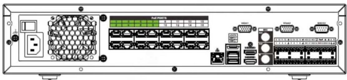
VGA1 VGA2 RS232 PwE PORTS 1 3 8 7 9 11 13 15 2 4 6 8 10 12 14 16The NVR58-16P-4KS2E series rear panel is shown as below. See Figure 2-49.
Figure 2-49
text_image
Pac PdRTB 1 2 3 4 5 6 7 8 9 10 11 12 13 14 15 VGA1 VGA2 WB222Table 2-22
| Name | Function | |
 | Power switch | Power on-off button |
 | Power input port | Input AC 100~240V. |
 | Network port | 10M/100M/1000Mbps self-adaptive Ethernet port. Connect to the network cable. |
| eSATA | eSATA port | External SATA port. It can connect to the device of the SATA port. Please jump the HDD when there is peripheral connected HDD. |
| ss←→ | USB3.0 port | USB3.0 port. Connect to mouse, USB storage device, USB burner and etc. |
| HDMI | High Definition Media Interface | High definition audio and video signal output port. It transmits uncompressed high definition video and multiple-channel data to the HDMI port of the display device. HDMI version is 1.4b. |
| MIC IN | Audio input port | Bidirectional talk input port. It is to receive the analog audio signal output from the devices such as microphone, pickup. |
| MIC OUT | Audio output port | Audio output port. It is to output the analog audio signal to the devices such as the sound box.Bidirectional talk output.Audio output on 1-window video monitor.Audio output on 1-window video playback. |
| 1~16 | Alarm input port 1~16 | There are four groups. The first group is from port 1 to port 4, the second group is from port 5 to port 8, the third group is from 9 to 12, and the fourth group is from 13 to 16. They are to receive the signal from the external alarm source. There are two types; NO (normal open)/NC (normal close).When your alarm input device is using external power, please make sure the device and the NVR have the same ground. |
| ⊥ | Ground | Alarm input ground end. |
| NO1~NO5 | Alarm output port 1~5 | 5 groups of alarm output ports. (Group 1:port NO1~C1, Group 2:port NO2~C2, Group 3:port NO3~C3, Group 4:port NO4~C4, Group 5: port NO5, C5, NC5). Output alarm signal to the alarm device. Please make sure there is power to the external alarm device.NO: Normal open alarm output port.C: Alarm output public end.NC: Normal close alarm output port. |
| C1~C5 | ||
| NC5 | ||
| A | RS-485 communication port | RS485_A port. It is the cable A. You can connect to the control devices such as speed dome PTZ. |
| B | RS485_B. It is the cable B. You can connect to the control devices such as speed dome PTZ. | |
| CTRL 12V | / | Controller 12V power output. It is to control the on-off alarm relay output. It can be used to control the device alarm output. At the same time, it can also be used as the power input source of some devices such as the alarm detector. |
| +12V | / | +12V power output port. It can provide the power to some peripheral devices such as the camera or the alarm device. Please note the supplying power shall be below 1A. |
| RS-232 | RS232 debug COM. | It is for general COM debug to configure IP address or transfer transparent COM data. |
| VGA | VGA video output port | VGA video output port. Output analog video signal. It can connect to the monitor to view analog video. |
| PoE PORTS | / | Bult-in Switch. Support PoE or ePoE function.For ePoE series product, port 1 to port 8 are the ePoE ports. ePoE port supports 300 meters@100Mbps, 800 meters@10Mbps. Port 9 to port 16 are general PoE ports.The 16 PoE series product supports total 150W. |
2.2.11 NVR48/48-16P Series
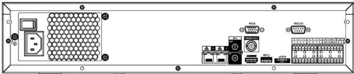
The NVR48 series rear panel is shown as below. See Figure 2-50.
Figure 2-50
text_image
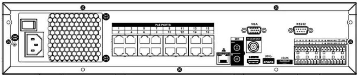
Diagram of an electronic device rear panel showing labeled ports and connectors including VGA, R5232, and network ports.The NVR48-16P series rear panel is shown as below. See Figure 2-51.
Figure 2-51
text_image
PoE PORTB 1 3 5 7 9 11 13 16 2 4 6 8 10 12 14 16 VGA RS232 MIC VIDEO OUT SPG- sSATATable 2-23
| Name | Function | |
| Power switch | / | Power on-off button |
| Power input port | / | Input AC 100~240V. |
| MIC IN | Audio input port | Bidirectional talk input port. It is to receive the analog audio signal output from the devices such as microphone, pickup. |
| MIC OUT | Audio output port | Audio output port. It is to output the analog audio signal to the devices such as the sound box.Bidirectional talk output.Audio output on 1-window video monitor.Audio output on 1-window video playback. |
| VIEDEO OUT | Video output port | CVBS output. |
| 1~16 | Alarm input port 1~16 | There are four groups. The first group is from port 1 to port 4, the second group is from port 5 to port 8, the third group is from 9 to 12, and the fourth group is from 13 to 16. They are to receive the signal from the external alarm source. There are two types; NO (normal open)/NC (normal close).When your alarm input device is using external power, please make sure the device and the NVR have the same ground. |
| ± | GND | Alarm input ground port. |
| NO1~NO5 | Alarm output port 1~5 | 5 groups of alarm output ports. (Group 1: port NO1~C1, Group 2: port NO2~C2, Group 3: port NO3~C3, Group 4: port NO4~C4, Group 5: port NO5, C5, NC5). Output alarm signal to the alarm device. Please make sure there is power to the external alarm device.NO: Normal open alarm output port.C: Alarm output public end.NC: Normal close alarm output port. |
| C1~C5 | ||
| NC5 | ||
| A | RS-485 communication port | RS485_A port. It is the cable A. You can connect to the control devices such as speed dome PTZ. |
| B | RS485_B. It is the cable B. You can connect to the control devices such as speed dome PTZ. | |
| CTRL 12V | / | Controller 12V power output. It is to control the on-off alarm relay output. It can be used to control the device alarm output. At the same time, it can also be used as the power input source of some devices such as the alarm detector. |
| +12V | /Network port | +12V power output port. It can provide the power to some peripheral devices such as the camera or the alarm device. Please note the supplying power shall be below 1A.One 10M/100M/1000Mbps self-adaptive Ethernet port. Connect to the network cable. |
| eSATA | eSATA port | External SATA port. It can connect to the device of the SATA port. Please jump the HDD when there is peripheral connected HDD. |
| USB2.0 port | USB2.0 port. Connect to mouse, USB storage device, USB burner and etc. | |
| RS-232 | RS-232 debug COM. | It is for general COM debug to configure IP address or transfer transparent COM data. |
| HDMI | High Definition Media Interface | High definition audio and video signal output port. It transmits uncompressed high definition video and multiple-channel data to the HDMI port of the display device. HDMI version is 1.3. |
| VGA | VGA video output port | VGA video output port. Output analog video signal. It can connect to the monitor to view analog video. |
| PoE PORTS | 16 PoE ports | Built-in Switch. Support PoE. The 16 PoE ports series products supports total 150W power. One PoE port max supports 15W. |
2.2.12 NVR42V-8P Series
The interface is shown as in Figure 2-52.
Figure 2-52

text_image
PoE PORTS VGA 1 2 3 4 5 6 7 MIC IN OUT HOUTTM SPTable 2-24
| Name | Function | |
| Power switch | / | Power on/off button. |
 | Power input port | Input DC 53V--2.3A |
| MIC IN | Audio input port | Bidirectional talk input port. It is to receive the analog audio signal output from the devices such as microphone, pickup. |
| MIC OUT | Audio output port | Audio output port. It is to output the analog audio signal to the devices such as the sound box.Bidirectional talk output.Audio output on 1-window video monitor.Audio output on 1-window video playback. |
| 1~2 | Alarm input port1~2 | When your alarm input device is using external power, please make sure the device and the NVR have the same ground. |
| 12 | GND | Alarm input ground port. |
| C | Alarm output public port | Alarm output public end. |
| NO | Normal open | Normal open alarm output port. |
| Network port | 10M/100M/1000Mbps self-adaptive Ethernet port. Connect to the network cable. | |
| SS | USB3.0 port | USB3.0 port. Connect to mouse, USB storage device, USB burner and etc. |
| HDMI | High Definition Media Interface | High definition audio and video signal output port. It transmits uncompressed high definition video and multiple-channel data to the HDMI port of the display device. HDMI version is 1.4. |
| VGA | VGA video output port | VGA video output port. Output analog video signal. It can connect to the monitor to view analog video. |
| PoE PORT | / | Bult-in Switch. Support PoE.The 8 PoE series product supports total 48V 120W.One PoE port max supports 15W. |
2.2.13 NVR41-4KS2/41-P-4KS2/41-8P-4KS2
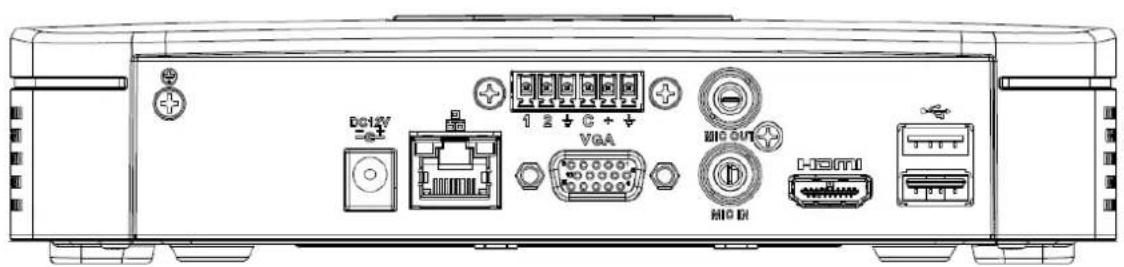
The NVR41-4KS2 series rear panel is shown as below. See Figure 2-53.
Figure 2-53
text_image
DC12V VGA HG HDMIThe NVR41-P-4KS2 series rear panel is shown as below. See Figure 2-54.
Figure 2-54
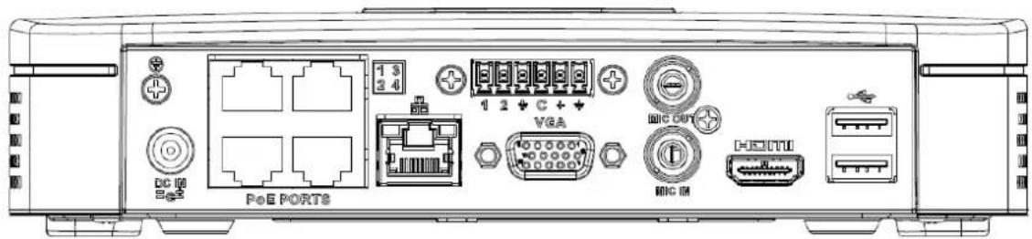
text_image
PoE PORTS 1 3 3 4 1 2 + C + VGA MIG OUT MIG IM HESIWIThe NVR41-8P-4KS2 series rear panel is shown as below. See Figure 2-55.
Figure 2-55

text_image
DC 10 2.45 PeE PORTB VGA HSC USB HSC USBTable 2-25
| Port Name | Connection | Function |
| USB port | USB port. Connect to mouse, USB storage device, USB burner and etc. | |
| Network port | 10M/100Mbps self-adaptive Ethernet port. Connect to the network cable. | |
| HDMI | High Definition Media Interface | High definition audio and video signal output port. It transmits uncompressed high definition video and multiple-channel data to the HDMI port of the display device. HDMI version is 1.4. |
| VGA | VGA video output port | VGA video output port. Output analog video signal. It can connect to the monitor to view analog video. |
| GND | Ground end | |
| DC12V / DC IN | Power input port | Power socket.For NVR41-4KS2: DC 12V/2A power.For NVR41-P-4KS2: DC 48V/72W power.For NVR41-8P-4KS2: DC 48V/96W power. |
| MIC IN | Audio input port | Bidirectional talk input port. It is to receive the analog audio signal output from the devices such as microphone, pickup. |
| MIC OUT | Audio output port | Audio output port. It is to output the analog audio signal to the devices such as the sound box.Bidirectional talk output.Audio output on 1-window video monitor.Audio output on 1-window video playback. |
| PoE PORT | PoE port | Built-in switch. Support PoE function.For PoE series product, you can use this port to provide power to the network camera. |
2.2.14 NVR41HS-4KS2/41HS-P-4KS2/41HS-8P-4KS2
The NVR41HS-4KS2 series rear panel is shown as below. See Figure 2-56.
Figure 2-56

text_image
1 X + G + + DIG OUT VGA I/O D-320V I/OThe NVR41HS-P-4KS2 series rear panel is shown as below. See Figure 2-57.
Figure 2-57

text_image
PoE PORTS 1 2 DC IN 2 4 VGA MIC OUT MIC IN HEDLINEThe NVR41HS-8P-4KS2 series rear panel is shown as below. See Figure 2-58.
Figure 2-58

text_image
PeE PORT8 1 3 5 7 DC IN 1 4 6 8 1 2 + C + VGA MIC IN HOC OUT I HESOUTable 2-26
| Port Name | Connection | Function |
| USB port | USB port. Connect to mouse, USB storage device, USB burner and etc. | |
| DC12V / DC IN | Power input port | Power socket.For NVR41HS-4KS2: DC 12V/2A power.For NVR41HS-P-4KS2: DC 48V/72W power.For NVR41HS-8P-4KS2: DC 48V/96W power. |
| Network port | 10M/100Mbps self-adaptive Ethernet port. Connect to the network cable. | |
| USB port | USB port. Connect to mouse, USB storage device and etc. | |
| HDMI | High Definition Media Interface | High definition audio and video signal output port. It transmits uncompressed high definition video and multiple-channel data to the HDMI port of the display device. HDMI version is 1.4. |
| VGA | VGA video output port | VGA video output port. Output analog video signal. It can connect to the monitor to view analog video. |
| MIC IN | Audio input port | Bidirectional talk input port. It is to receive the analog audio signal output from the devices such as microphone, pickup. |
| MIC OUT | Audio output port | Audio output port. It is to output the analog audio signal to the devices such as the sound box.Bidirectional talk output.Audio output on 1-window video monitor.Audio output on 1-window video playback. |
| ± | GND | Ground end |
| PoE PORTS | PoE port | Built-in switch. Support PoE function.For PoE series product, you can use this port to provide power to the network camera. |
2.2.15 NVR42-4KS2/42-P-4KS2/42-8P-4KS2/42-16P-4KS2
The NVR42-4KS2 series rear panel is shown as below. See Figure 2-59.
Figure 2-59

text_image
SP MTC VGA HDMI DC1W ON OFFThe NVR42-P-4KS2 series rear panel is shown as below. See Figure 2-60.
Figure 2-60

text_image
ON OFF DS IN PME PORTS 1 3 2 4 SS+ MDC VGA HDMIThe NVR42-8P-4KS2 series rear panel is shown as below. See Figure 2-61.
Figure 2-61

text_image
PGE PORTS 1 3 5 7 2 4 6 8 GPIO VGA HDMIThe NVR42-16P-4KS2 series rear panel is shown as below. See Figure 2-62.
Figure 2-62

text_image
1 3 5 7 9 11 13 15 PrePORTS VGA RS232 HDMI SS MICTable 2-27
| Name | Function | |
| [XABA] | Power switch | Power on/off button. |
 | ||
 | Power input port | Input DC 12V/4A.For NVR42-4KS2 series product only. |
 | Switch power port. Input DC 48/96WFor NVR42-P-4KS2 series product only. | |
 | Input AC90V~264V-12V5A/52V2.5A-190W.For NVR42-8P-4KS2/NVR42-16P-4KS2 series product only. | |
| MIC IN | Audio input port | Bidirectional talk input port. It is to receive the analog audio signal output from the devices such as microphone, pickup. |
| MIC OUT | Audio output port | Audio output port. It is to output the analog audio signal to the devices such as the sound box.Bidirectional talk output.Audio output on 1-window video monitor.Audio output on 1-window video playback. |
| 1~4 | Alarm input port1~4 | There are two types; NO (normal open)/NC (normal close).When your alarm input device is using external power, please make sure the device and the NVR have the same ground. |
| ± | GND | Alarm input ground port. |
| N1, N2 | Alarm output port1~2 | 2 groups of alarm output ports. (Group 1:port NO1~C1, Group 2:port NO2~C2). Output alarm signal to the alarm device. Please make sure there is power to the external alarm device.NO: Normal open alarm output port.C: Alarm output public end. |
| C1, C2 | ||
| A | RS-485 communication port | RS485_A port. It is the cable A. You can connect to the control devices such as speed dome PTZ. |
| B | RS485_B. It is the cable B. You can connect to the control devices such as speed dome PTZ. | |
| Network port | 10M/100M/1000Mbps self-adaptive Ethernet port. Connect to the network cable. | |
| USB port | USB port. Connect to mouse, USB storage device, USB burner and etc. | |
| RS-232 | RS-232 debug COM. | It is for general COM debug to configure IP address or transfer transparent COM data. |
| HDMI | High Definition Media Interface | High definition audio and video signal output port. It transmits uncompressed high definition video and multiple-channel data to the HDMI port of the display device. HDMI version is 1.4. |
| VGA | VGA video output port | VGA video output port. Output analog video signal. It can connect to the monitor to view analog video. |
| PoE PORTS | / | Built-in Switch. Support PoE.For PoE series product, you can use this port to provide power to the network camera. |
2.2.16 NVR44-4KS2/44-16P-4KS2
The NVR44-4KS2 series rear panel is shown as below. See Figure 2-63.
Figure 2-63

text_image
Labeled diagram of a device rear panel showing internal components like battery, connectors, and ports like RS232, VGA, HDMI, and I/O ports.The NVR44-16P-4KS2 series rear panel is shown as below. See Figure 2-64.
Figure 2-64

text_image
PUE PORTS 1 3 5 7 9 11 13 15 2 4 6 8 10 12 14 16 MIC RS232 VGA HDTV 12:54:15:16:00:00:00:00:00:00:00:00:00:00:00:00:00:00:00:00:00:00:00:00:00:00:00:00:00:00:00:00:00:00:00:00:00:00 1 2 3 4 5 6 7 8 9 10 11 12 13 14 15 HDTV HDTV HDTVTable 2-28
| Name | Function | |
| Power switch | / | Power on-off button |
| Power input port | / | AC90V~264V-12V12.5A/-53V2.83A |
| MIC IN | Audio input port | Bidirectional talk input port. It is to receive the analog audio signal output from the devices such as microphone, pickup. |
| MIC OUT | Audio output port | Audio output port. It is to output the analog audio signal to the devices such as the sound box.Bidirectional talk output.Audio output on 1-window video monitor.Audio output on 1-window video playback. |
| VIEDEO OUT | Video output port | CVBS output |
| 1~16 | Alarm input port 1~16 | There are four groups. The first group is from port 1 to port 4, the second group is from port 5 to port 8, the third group is from 9 to 12, and the fourth group is from 13 to 16. They are to receive the signal from the external alarm source. There are two types; NO (normal open)/NC (normal close).When your alarm input device is using external power, please make sure the device and the NVR have the same ground. |
| ± | Video output port | CVBS output |
| NO1~NO5 | Alarm output port 1~5 | 5 groups of alarm output ports. (Group 1:port NO1~C1, Group 2:port NO2~C2, Group 3:port NO3~C3, Group 4:port NO4~C4, Group 5: port NO5, C5, NC5). Output alarm signal to the alarm device. Please make sure there is power to the external alarm device.NO: Normal open alarm output port.C: Alarm output public end.NC: Normal close alarm output port. |
| C1~C5 | ||
| NC5 | ||
| A | RS-485 communication port | RS485_A port. It is the cable A. You can connect to the control devices such as speed dome PTZ. |
| B | RS485_B. It is the cable B. You can connect to the control devices such as speed dome PTZ. | |
| CTRL 12V | / | Controller 12V power output. It is to control the on-off alarm relay output. It can be used to control the device alarm output. At the same time, it can also be used as the power input source of some devices such as the alarm detector. |
| +12V | / | +12V power output port. It can provide the power to some peripheral devices such as the camera or the alarm device. Please note the supplying power shall be below 1A. |
| Network port | 10M/100M/1000Mbps self-adaptive Ethernet port. Connect to the network cable. | |
| eSATA | eSATA port | External SATA port. It can connect to the device of the SATA port. Please jump the HDD when there is peripheral connected HDD. |
| USB2.0 port | USB2.0 port. Connect to mouse, USB storage device, USB burner and etc. | |
| RS-232 | RS232 debug COM. | It is for general COM debug to configure IP address or transfer transparent COM data. |
| HDMI | High Definition Media Interface | High definition audio and video signal output port. It transmits uncompressed high definition video and multiple-channel data to the HDMI port of the display device. HDMI version is 1.3 |
| VGA | VGA video output port | VGA video output port. Output analog video signal. It can connect to the monitor to view analog video. |
| PoE PORTS | PoE port | Built-in Switch. Support PoE.For PoE series product, you can use this port to provide power to the network camera. |
2.2.17 NVR48-4KS2/48-16P-4KS2 Series
The NVR48-4KS2 series rear panel is shown as below. See Figure 2-65.
Figure 2-65
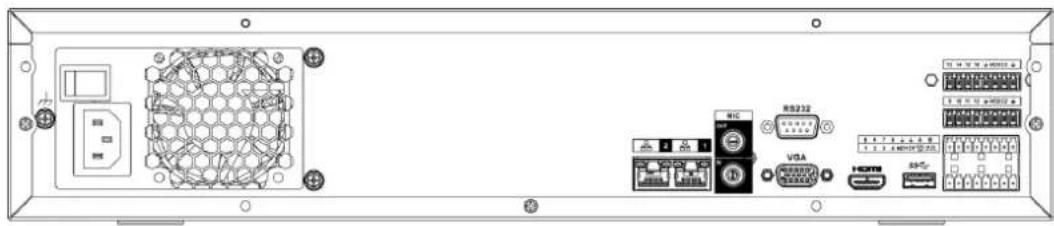
text_image
Technical diagram of an electronic device rear panel with labeled ports and connectorsThe NVR48-16P-4KS2 series rear panel is shown as below. See Figure 2-66.
Figure 2-66
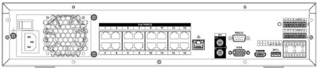
text_image
PxE PORTS 1 3 5 7 9 11 13 15 2 4 6 8 10 12 14 16 I/O VGA RS232 HORN USBTable 2-29
| Name | Function | |
| Power switch | / | Power on-off button |
| Power input port | / | AC90V~264V-12V12.5A/-53V2.83A |
| MIC IN | Audio input port | Bidirectional talk input port. It is to receive the analog audio signal output from the devices such as microphone, pickup. |
| MIC OUT | Audio output port | Audio output port. It is to output the analog audio signal to the devices such as the sound box.Bidirectional talk output.Audio output on 1-window video monitor.Audio output on 1-window video playback. |
| VIEDEO OUT | Video output port | CVBS output. |
| 1~16 | Alarm input port 1~16 | There are four groups. The first group is from port 1 to port 4, the second group is from port 5 to port 8, the third group is from 9 to 12, and the fourth group is from 13 to 16. They are to receive the signal from the external alarm source. There are two types; NO (normal open)/NC (normal close).When your alarm input device is using external power, please make sure the device and the NVR have the same ground. |
| [2347] | GND | Alarm input ground port. |
| NO1~NO5 | Alarm output port 1~5 | 5 groups of alarm output ports. (Group 1:port NO1~C1, Group 2:port NO2~C2, Group 3:port NO3~C3, Group 4:port NO4~C4, Group 5: port NO5, C5, NC5). Output alarm signal to the alarm device. Please make sure there is power to the external alarm device.NO: Normal open alarm output port.C: Alarm output public end.NC: Normal close alarm output port. |
| C1~C5 | ||
| NC5 | ||
| A | RS-485 communication port | RS485_A port. It is the cable A. You can connect to the control devices such as speed dome PTZ. |
| B | RS485_B. It is the cable B. You can connect to the control devices such as speed dome PTZ. | |
| CTRL 12V | / | Controller 12V power output. It is to control the on-off alarm relay output. It can be used to control the device alarm output. At the same time, it can also be used as the power input source of some devices such as the alarm detector. |
| +12V | / | +12V power output port. It can provide the power to some peripheral devices such as the camera or the alarm device. Please note the supplying power shall be below 1A. |
 | Network port | One 10M/100M/1000Mbps self-adaptive Ethernet port. Connect to the network cable. |
| eSATA | eSATA port | External SATA port. It can connect to the device of the SATA port. Please jump the HDD when there is peripheral connected HDD. |
| [2HA2] | USB port | USB port. Connect to mouse, USB storage device, USB burner and etc. |
| RS-232 | RS-232 debug COM. | It is for general COM debug to configure IP address or transfer transparent COM data. |
| HDMI | High Definition Media Interface | High definition audio and video signal output port. It transmits uncompressed high definition video and multiple-channel data to the HDMI port of the display device. HDMI version is 1.4. |
| VGA | VGA video output port | VGA video output port. Output analog video signal. It can connect to the monitor to view analog video. |
| PoE PORTS | PoE port | Built-in Switch. Support PoE.For PoE series product, you can use this port to provide power to the network camera. |
2.2.18 NVR21-W-4KS2 Series
The rear panel is shown as below. See Figure 2-67.
Figure 2-67
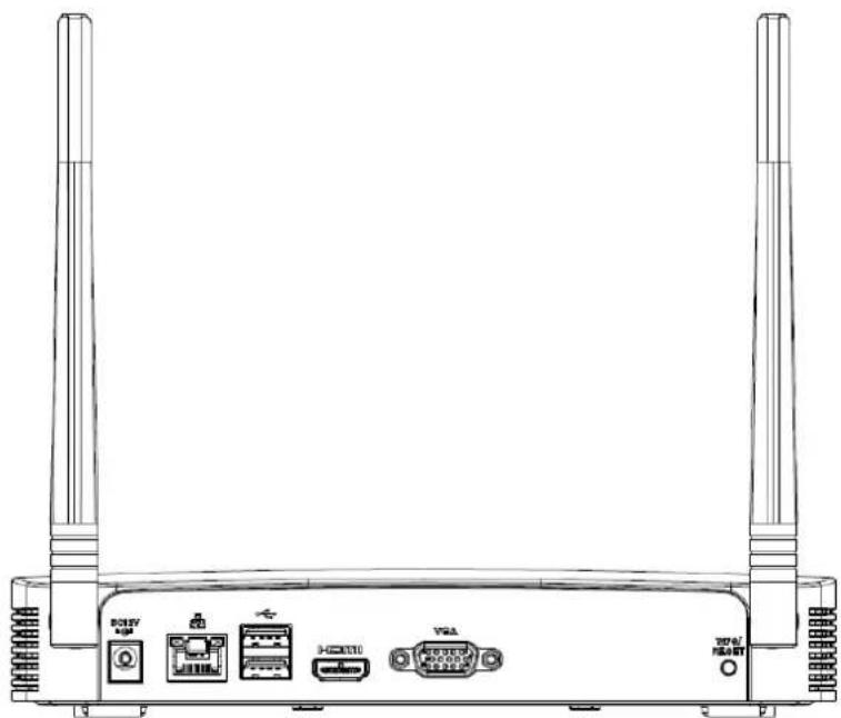
natural_image
Line drawing of a wireless router with two towers and four ports (no text or symbols)Table 2-30
| Port Name | Connection | Function |
 | USB2.0 port | USB2.0 port. Connect to mouse, USB storage device, USB burner and etc. |
 | Network port | 10M/100Mbps self-adaptive Ethernet port. Connect to the network cable. |
| HDMI | High Definition Media Interface | High definition audio and video signal output port. It transmits uncompressed high definition video and multiple-channel data to the HDMI port of the display device. HDMI version is 1.4. |
| VGA | VGA video output port | VGA video output port. Output analog video signal. It can connect to the monitor to view analog video. |
 | Power input port | Input DC 12V/2A. |
| WPS/RESET | Reset/WPS function | Device Wi-Fi reset and WPS function button:● Hold down this button for 5 seconds and above to restore Wi-Fi AP to defaults.● Press this button for less than 2 seconds, and then press the WPS button of Wi-Fi IPC, the device and Wi-Fi IPC can be connected. |
2.2.19 NVR21HS-W-4KS2 Series
The rear panel is shown as below. See Figure 2-68.
Figure 2-68
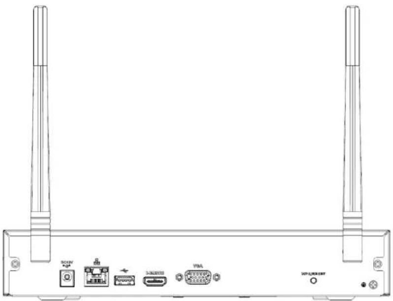
natural_image
Front view of a network device rear panel with ports and connectors (no text or symbols visible)Table 2-31
| Icon | Name | Function |
| DC12V | Power input socket. | Power socket. Input DC12V/2A. |
| Network port | 10M/100Mbps self-adaptive Ethernet port. Connect to the network cable. | |
| USB2.0 port | USB2.0 port. Connect to mouse, USB storage device, and etc. | |
| HDMI | High Definition Media Interface | High definition audio and video signal output port. It transmits uncompressed high definition video and multiple-channel data to the HDMI port of the display device. HDMI version is 1.4. |
| VGA | VGA video output port | VGA video output port. Output analog video signal. It can connect to the monitor to view analog video. |
| GND | Ground end | |
| WPS/RESET | Reset/WPS function | Device Wi-Fi reset and WPS function button:Hold down this button for 5 seconds and above to restore Wi-Fi AP to defaults.Press this button for less than 2 seconds, and then press the WPS button of Wi-Fi IPC, the device and Wi-Fi IPC can be connected. |
2.3 Alarm Connection
2.3.1 Alarm Port
The alarm port is shown as below. See Figure 2-69. The following figure for reference only.
Figure 2-69
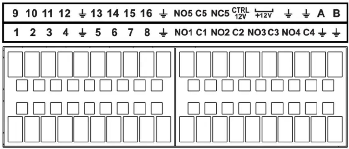
| Icon | Function |
| 1~16 | ALARM1~ALARM16. The alarm becomes activated in the low level. |
| NO1 C1, NO2 C2, NO3 C3, NO4 C4 | Four NO activation output groups. (On-off button). |
| NO5 C5 NC5 | One NO/NC activation output group. (On-off button). |
| CTRL 12V | Control power output. Disable power output when alarm is canceled. Current is 500mA. |
| +12V | Rated current output. Current is 500mA. |
 | GND |
| A/B | 485 communication port. They are used to control devices such as PTZ. Please parallel connect 120TΩ between A/B cables if there are too many PTZ decoders. |
Note
- Different models support different alarm input ports. Please refer to the specifications sheet for detailed information.
- Slight difference may be found on the alarm port layout.
2.3.2 Alarm input port
Connect the positive end (+) of the alarm input device to the alarm input port (ALARM IN 1\~16) of the
NVR. Connect the negative end (-) of the alarm input device to the ground end ( ) of the NVR.
Figure 2-70
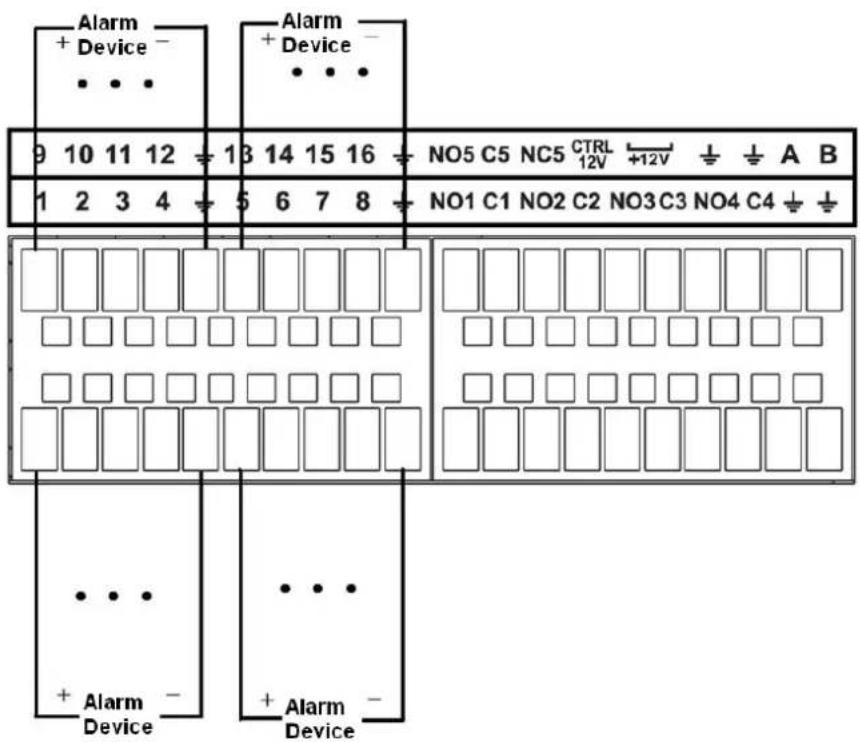
text_image
Alarm + Device - • • • Alarm + Device - • • • 9 10 11 12 13 14 15 16 NO5 C5 NC5 CTRL 12V +12V ± ± A B 1 2 3 4 5 6 7 8 NO1 C1 NO2 C2 NO3 C3 NO4 C4 ± ± • • • + Alarm - • • • Device Device
NOTE
● There are two alarm input types: NO/NC.
- When connect the ground port of the alarm device to the NVR, you can use any of the GND ports

- Connect the NC port of the alarm device to the alarm input port (ALARM) of the NVR.
- When there is peripheral power supplying for the alarm device, please make sure it is earthed with the NVR.
2.3.3 Alarm input and output port
● There is peripheral power supplying for the external alarm device.
- In case overload may result in NVR damage, please refer to the following relay specifications for detailed information.
● A/B cable of the RS485 is for the A/B cable connection of the speed PTZ.
2.3.4 Alarm relay specifications
Table 2-33
| Model: JRC-27F | ||
| Material of the touch | Silver | |
| Rating (Resistance Load) | Rated switch capacity | 30VDC 2A, 125VAC 1A |
| Maximum switch power | 125VA 160W | |
| Maximum switch voltage | 250VAC, 220VDC | |
| Maximum switch currency | 1A | |
| Insulation | Between touches with same polarity | 1000VAC 1minute |
| Between touches with different polarity | 1000VAC 1minute | |
| Between touch and winding | 1000VAC 1minute | |
| Surge voltage | Between touches with same polarity | 1500V (10×160us) |
| Length of open time | 3ms max | |
| Length of close time | 3ms max | |
| Longevity | Mechanical | 50×106 MIN (3Hz) |
| Electrical | 200×103 MIN (0.5Hz) | |
| Temperature | -40°C - +70°C | |
2.4 Bidirectional talk
2.4.1 Device-end to PC-end
Device Connection
Please connect the speaker or the pickup to the first audio input port in the device rear panel. Then connect the earphone or the sound box to the audio output port in the PC.
Login the Web and then enable the corresponding channel real-time monitor.
Please refer to the following interface to enable bidirectional talk. See Figure 2-71.
Figure 2-71
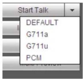
text_image
Start Talk DEFAULT G711a G711u PCMListening Operation
At the device end, speak via the speaker or the pickup, and then you can get the audio from the earphone or sound box at the pc-end. See Figure 2-72.
Figure 2-72

flowchart
graph LR
    A["Device"] -->|Signal Transmission| B["Internet Explorer"]
    B --> C["Computer"]
2.4.2 PC-end to the device-end
Device Connection
Connect the speaker or the pickup to the audio output port in the PC and then connect the earphone or the sound box to the first audio input port in the device rear panel.
Login the Web and then enable the corresponding channel real-time monitor.
Please refer to the above interface (Figure 2-71) to enable bidirectional talk.
Listening Operation
At the PC-end, speak via the speaker or the pickup, and then you can get the audio from the earphone or sound box at the device-end. See Figure 2-73.
Figure 2-73
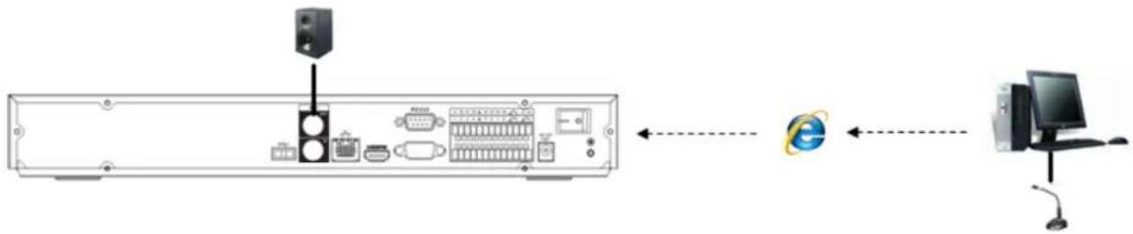
flowchart
graph LR
    A["Front Panel"] --> B["I/O Interface"]
    B --> C["Computer"]
    D["Internet"] <--> E["Internal Interface"]
2.5 Mouse Operation
Refer to the following sheet for mouse operation instruction.
Table 2-34
| Left click mouse | When you have selected one menu item, left click mouse to view menu content. |
| Modify checkbox or motion detection status. | |
| Click combo box to pop up dropdown list | |
| In input box, you can select input methods. Left click the corresponding button on the panel you can input numeral/English character (small/capitalized). Here← stands for backspace button. _ stands for space button.In English input mode: _stands for input a backspace icon and ← stands for deleting the previous character. | |
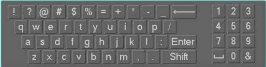 | |
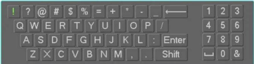 | |
| In numeral input mode: _ stands for clear and ← stands for deleting the previous numeral. | |
| Double left click mouse | Implement special control operation such as double click one item in the file list to playback the video.In multiple-window mode, double left click one channel to view in full-window. Double left click current video again to go back to previous multiple-window mode. |
| Right click mouse | In real-time monitor mode, pops up shortcut menu. |
| Exit current menu without saving the modification. | |
| Press middle button | In numeral input box: Increase or decrease numeral value. |
| Switch the items in the check box. | |
| Page up or page down | |
| Move mouse | Select current control or move control |
| Drag mouse | Select motion detection zone |
| Select privacy mask zone. |
2.6 Remote Control
The remote control interface is shown as in Figure 2-74.
Please note remote control is not our standard accessory and it is not included in the accessory bag.
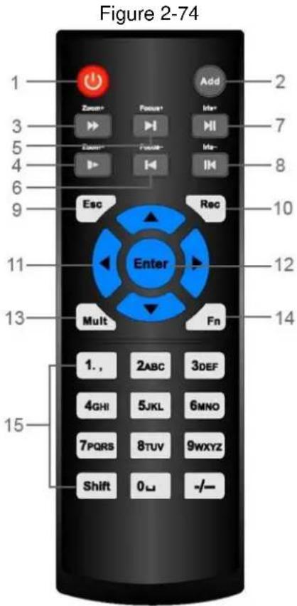
text_image
Figure 2-74 1 Zone+ Focus+ Add 2 3 IId= 7 5 Zoom+ Focus- IId= 4 Esc Rec 8 9 Enter 10 11 12 13 Mult Fn 1. 2ABC 3DEF 4GHI 5JKL 6MNO 7PQRS 8TUV 9WXYZ Shift 0- +/- 15Table 2-35
| No. | Name | Function |
| 1 | Power button | Press this button to boot up or shut down the device. |
| 2 | Address | Press this button to input device serial number, so that you can control the Device. |
| 3 | Forward | Multi-step forward speed and normal speed playback. |
| 4 | Slow motion | Multi-step slow motion speed or normal playback. |
| 5 | Next record | In playback state, press this button to play back the next video. |
| 6 | Previous record | In playback state, press this button to play back the previous video. |
| 7 | Play/Pause | In normal playback state, press this button to pause playback.In pause state, press this button to resume to normal playback.In live view window interface, press this button to enter video search menu. |
| 8 | Reverse/pause | In the reverse playback state, press this button to pause reverse playback. |
| In the reverse playback pause state, press this button to resume to playback reversing state. | ||
| 9 | Esc. | Go back to previous menu or cancel current operation (close front interface or control). |
| 10 | Record | Start or stop record manually.In record interface, use the direction buttons to select the channel that you want to record.Press this button for at least 1.5 seconds, and the manual record interface will be displayed. |
| 11 | Direction keys | Switch between current activated controls by going left or right.In playback state, the keys control the playback progress bar.Aux function (such as operating the PTZ menu). |
| 12 | Enter/menu key | Confirms an operation.Go to the OK button.Go to the menu. |
| 13 | Multiple-window switch | Switch between multiple-window and one-window. |
| 14 | Fn | In single-channel monitoring mode, press this button to display the PTZ control and color setting functions.Switch the PTZ control menu in PTZ control interface.In motion detection interface, press this button with direction keys to complete setup.In text mode, press and hold this button to delete the last character. To use the clearing function: Long press this button for 1.5 seconds.In HDD menu, switch HDD recording time and other information as indicated in the pop-up message. |
| 15 | Alphanumeric keys | Input password, numbers.Switch channel.Press Shift to switch the input method. |
Note: All the installation and operations here should conform to your local electric safety rules.
3.1 Device Installation Diagrams
Please refer to the following diagrams to install the NVR.
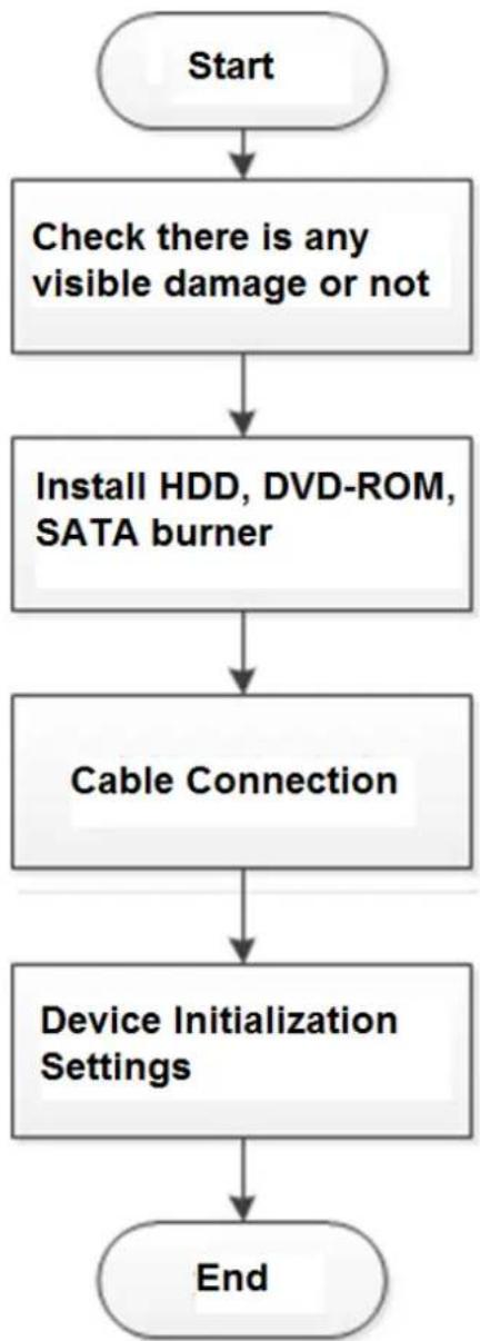
flowchart
graph TD
    A["Start"] --> B["Check there is any visible damage or not"]
    B --> C["Install HDD, DVD-ROM, SATA burner"]
    C --> D["Cable Connection"]
    D --> E["Device Initialization Settings"]
    E --> F["End"]
3.2 Check Unpacked NVR
When you receive the NVR from the forwarding agent, please check whether there is any visible damage. The protective materials used for the package of the NVR can protect most accidental clashes during transportation. Then you can open the box to check the accessories.
Please check the items in accordance with the list. Finally you can remove the protective film of the NVR.
3.3 About Front Panel and Rear Panel
The model number in the stick on the bottom of NVR is very important; please check according to your purchase order.
The label in the rear panel is very important too. Usually we need you to represent the serial number when we provide the service after sales.
3.4 HDD Installation
For the first time installation, make sure whether the HDD has been installed or not. We recommend to use HDD of enterprise level or surveillance level. It is not recommended to use PC HDD.

CAUTION
● Shut off the power before you replace the HDD.
- Use the dedicated SATA HDD for monitoring recommended by the HDD manufacturer.
- You can refer to the Appendix for HDD space information and recommended HDD brand.
3.4.1 NVR41/41-P/41-8P/41-W/21-S2/21-P-S2/21-8P-S2/41-4KS2/41-P-4KS2/41-8P-4KS2/21-4KS2/21-P-4KS2/21-8P-4KS2/21-W-4KS2 Series
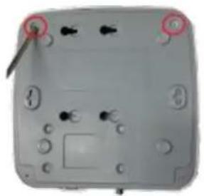
natural_image
Close-up of a gray electronic device casing with mounting holes and control buttons (no visible text or symbols)① Loosen the screws of the bottom of the chassis.
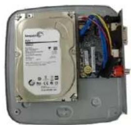
natural_image
Internal view of an open hard drive with visible circuit board and ports (no readable text or symbols)② Place the HDD in accordance with the four holes in the bottom.
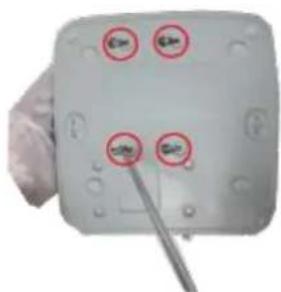
natural_image
Close-up of a handheld device with four circular icons and a pen inserted, no visible text or symbols.③ Turn the device upside down and then secure the screws firmly.
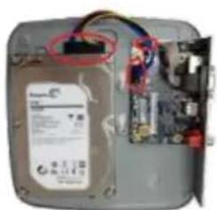
natural_image
Interior view of a computer case showing internal components and wiring (no visible text or symbols)④ Connect the HDD cable and power cable to the HDD and the mainboard respectively.
natural_image
Plain white rectangular object with a small square cutout on top (no text or symbols)⑤ Put the cover back and then fix the screws of the rear panel. The installation
is complete.
3.4.2 NVR41H/41H-P/41H-8P/21HS-S2/21HS-P-S2/21HS-8P-S2/41HS-W-S2/41HS-4KS 2/41HS-P-4KS2/41HS-8P-4KS2/21HS-4KS2/21HS-P-4KS2/21HS-8P-4KS2/21HS-W-4KS2 Series
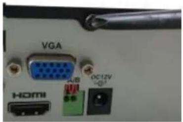
text_image
VGA HDMI USB OC12V +5① Loosen the screws of the upper cover and side panel.
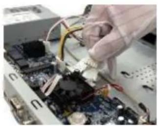
natural_image
Close-up of hands assembling electronic circuit boards with wires and components (no visible text or symbols)② Connect the one end of the HDD data cable and the power cable to the mainboard.
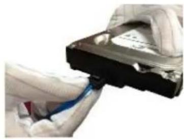
natural_image
Close-up of hands holding a black hard drive with a blue cable, no visible text or symbols③ Connect the other end of the HDD data cable and the power cable to the HDD.
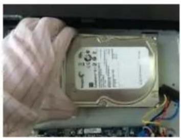
natural_image
Hand holding a hard disk drive with visible internal components and wiring (no readable text or symbols)④ Place the HDD in accordance with the four holes on the bottom of the chassis.

natural_image
Close-up of a gloved hand holding a screwdriver on a metal tray with perforated holes (no text or symbols visible)⑤ Turn the device upside down; fix the screws to secure the HDD on the bottom of the chassis.
natural_image
Black rectangular electronic device with a flat top and a flat base (no visible text or symbols)⑥ Put the cover in accordance with the clip and then fix the screws on the rear panel and side panel.
3.4.3 NVR42/42N/42-P/42-8P/42-16P/42-4K/42-8P-4K/52-4KS2/52-8P-4KS2/52-16P-4KS2/22-S2/22-P-S2/22-8P-S2/42-4KS2/42-P-4KS2/42-8P-4KS2/42-16P-4KS2/5224-24P-4KS2/22-4KS2/22-P-4KS2/22-8P-4KS2/52-8P-4KS2E/52-16P-4KS2E Series
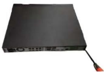
natural_image
Black electronic device with a red cable and label, no visible text or symbols on the body① Loosen the screws of the rear panel and side panel.
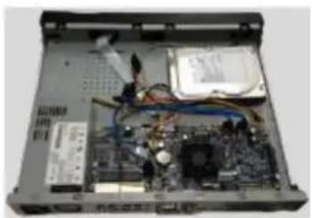
natural_image
Interior view of a computer setup with visible circuit board, RAM slots, and internal components (no text or symbols)② Place the HDD in accordance with the four holes in the bottom.
natural_image
Exterior view of a white electronic device casing with four mounting holes and ventilation grilles (no visible text or symbols)③ Turn the device upside down and then secure the screws firmly. It is to fix the HDD on the chassis.
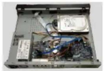
natural_image
Interior view of an open computer case showing internal components like CPU, memory, and wiring (no visible text or labels)
natural_image
Black rectangular electronic device with a red cable, no visible text or symbols on its body④Connect the HDD cable and power cable.
⑤Put the cover in accordance with the clip and then fix the screws on the rear panel and side panel.
3.4.4 NVR44/44-8P/44-16P/54-4KS2/54-16P-4KS2/44-4KS2/44-16P-4KS2/5424-24P-4KS2/54-16P-4KS2E Series
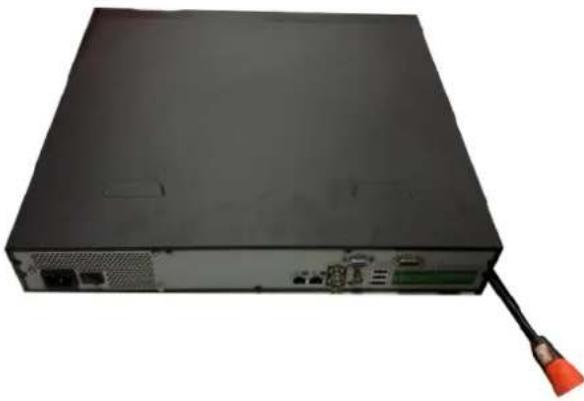
natural_image
Back view of a black server or network device with ports and a cable, no visible text or symbols① Use the screwdriver to loose the screws of the rear panel and then remove the front cover.
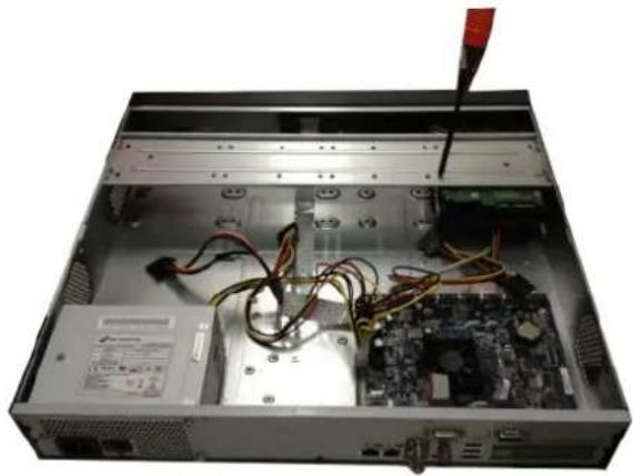
natural_image
Interior view of a computer drive bay showing internal components like CPU socket, RAM slots, and cable routing (no visible text or labels)② Put the HDD to the HDD bracket in the chassis and then line up the four screws to the four holes in the HDD. Use the screwdriver to fix the screws firmly to secure HDD on the HDD bracket
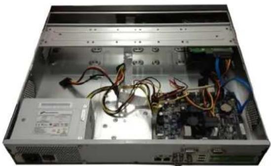
natural_image
Interior view of a computer rack with exposed circuit board and cable, no visible text or symbols③ Connect to the HDD data cable to the main board and the HDD port respectively. Loosen the power cable of the chassis and connect another end of the power cable to the HDD port.
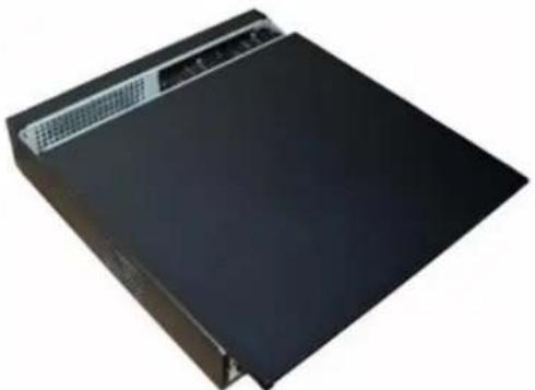
natural_image
Exterior view of a black electronic device with ventilation grilles (no text or symbols visible)④ After connect the cable, put the front cover back to the device and then fix screws of the rear panel.
3.4.5 NVR48/48-16P/58-4KS2/58-16P-4KS2/48-4KS2/48-16P-4KS2/52-16P-4KS2E Series
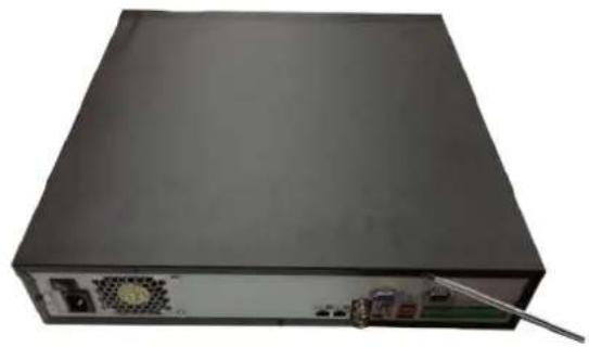
natural_image
Front view of a black server rack with ports and a cable inserted (no visible text or labels)① Use the screwdriver to loose the screws of the rear panel and then remove the front cover.
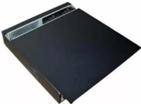
natural_image
Black rectangular electronic device with a top panel and ventilation grille (no visible text or symbols)② Put the HDD to the HDD bracket in the chassis and then line up the four screws to the four holes in the HDD. Use the screwdriver to fix the screws firmly to secure HDD on the HDD bracket
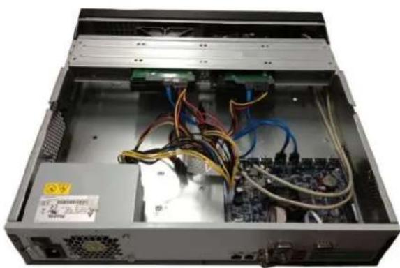
natural_image
Interior view of a server rack with exposed circuit board and cable, no visible text or symbols③ Connect to the HDD data cable to the main board and the HDD port respectively. Loosen the power cable of the chassis and connect another end of the power cable to the HDD port.
natural_image
Black rectangular electronic device with a ventilation grille and indicator lights (no visible text or symbols)④ After connect the cable, put the front cover back to the device and then fix screws of the rear panel.
3.4.6 NVR42V-8P Series
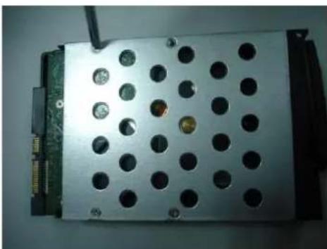
natural_image
Close-up of a metallic electronic device with circular perforations and a small orange component on the side (no visible text or symbols)① Use 4 screws to secure the HDD
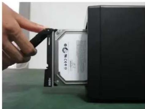
natural_image
Close-up of a hand inserting a plastic into a hard disk drive into a black CPU socket (no visible text or symbols)② Put the HDD to the HDD box at the front.
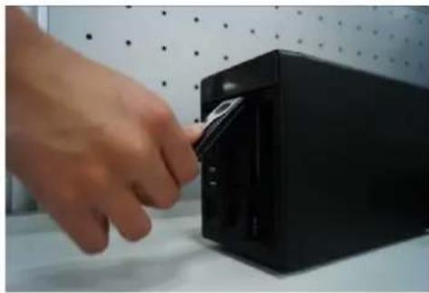
natural_image
Hand inserting a black drive into a black server rack on a white surface, with a dot-patterned wall in the background (no text or symbols visible)③ Pull the HDD knob up when you put the HDD into the box in case the knob buckle may strike the front panel.
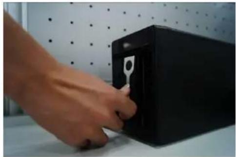
natural_image
Hand inserting a black plastic into a black box on a white surface, with a dotted wall and window in the background (no text or symbols visible)④ Put the knob back after you insert the HDD to the SATA board.
3.5 CD-ROM Installation
Please follow the steps listed below.
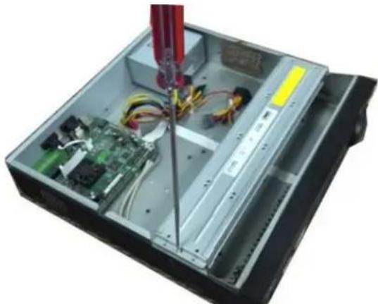
natural_image
Interior view of a computer drive bay with exposed circuit board and wiring, no visible text or symbols① Open top cover and then remove the HDD bracket
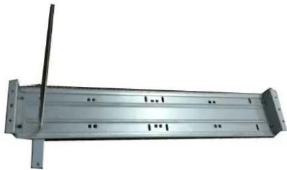
natural_image
Metal structural beam with vertical supports and a diagonal rod, no visible text or symbols③ Fix the CD-ROM bracket at the HDD bracket.
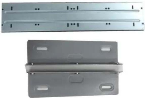
natural_image
Two metallic metal panels with internal slots and mounting holes, shown from different angles (no text or symbols visible)② Take off the bottom of the HDD bracket and CD-ROM bracket.
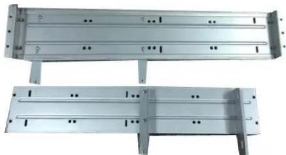
natural_image
Two metallic structural panels with internal channels and mounting holes, shown from different angles (no text or symbols visible)④ Install a pair of the CD-ROM bracket. Please make sure the reverse side is secure too.
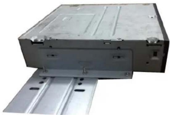
natural_image
Exterior view of a metallic electronic device with mounting brackets and mounting holes (no text or symbols visible)⑤ Install SATA burner. Line up the SATA burner to the hole positions.
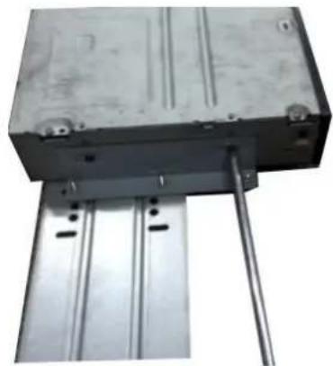
natural_image
Metallic rectangular block mounted on a metal frame with a vertical rod inserted (no visible text or symbols)⑥ User screwdriver to fix the screws.
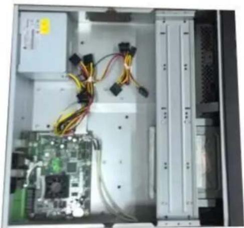
natural_image
Interior view of an electronic equipment cabinet showing CPU socket, wiring, and power connectors (no visible text or labels)⑦ Put the bracket back. Please adjust the CD-ROM to the proper position so that the button of the front panel is directly facing the pop-up button of the CD-ROM.
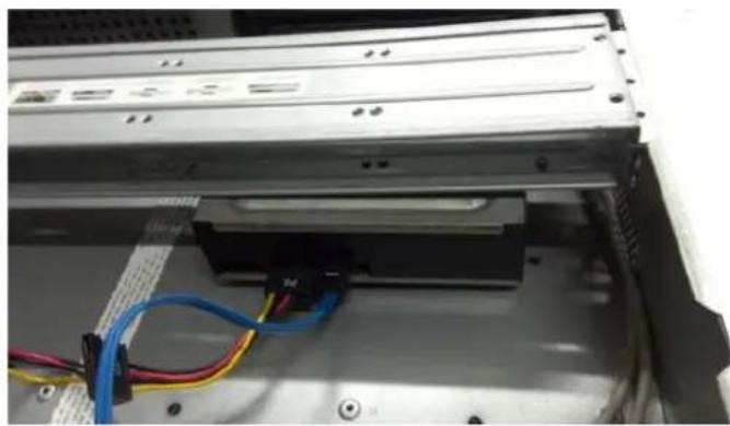
natural_image
Interior view of a computer drive bay showing internal components and cable routing (no visible text or symbols)⑧ Connect the SATA cable and power wire.
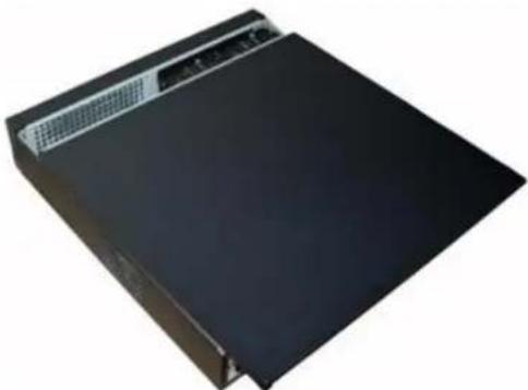
natural_image
Exterior view of a black server rack with ventilation grilles (no text or symbols visible)⑨ Secure the HDD bracket and put the top cover back.
3.6 Connection Sample
3.6.1 NVR41/41-P/41-8P/41-W/21-S2/21-P-S2/21-8P-S2/41-4KS2/41-P-4KS2/41-8P-4KS2/21-4KS2/21-P-4KS2/21-8P-4KS2 Series
Please refer to Figure 3-1 for connection sample.
The following figure for reference only.
Figure 3-1
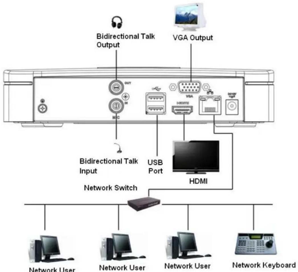
text_image
Bidirectional Talk Output VGA Output Bidirectional Talk Input USB Port HDMI Network Switch Network User Network User Network User Network Keyboard3.6.2 NVR41H/41H-P/41H-8P Series
Please refer to Figure 3-2 for connection sample.
The following figure for reference only.
Figure 3-2
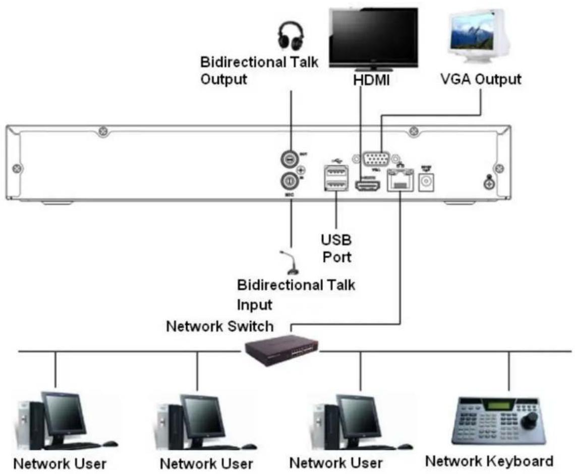
flowchart
graph TD
    A["Bidirectional Talk Output"] --> B["USB Port"]
    C["HDMI"] --> D["Device 1"]
    E["VGA Output"] --> F["Device 2"]
    G["Bidirectional Talk Input"] --> H["Network Switch"]
    I["Network User"] --> J["Computer"]
    K["Network User"] --> L["Computer"]
    M["Network User"] --> N["Computer"]
    O["Network Keyboard"] --> P["Computer"]
3.6.3 NVR41HS-W-S2/21-W-4KS2/21HS-W-4KS2 Series
Please refer to Figure 3-3 for connection sample.
The following figure for reference only.
Figure 3-3
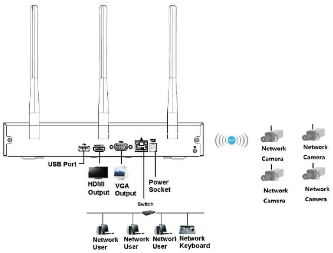
text_image
USB Port HDMI Output VGA Output Power Socket Switch Network User Network User Network User Network Keyboard Network Camera Network Camera Network Camera Network Camera3.6.4 NVR21HS-S2/21HS-P-S2/21HS-8P-S2/41HS-4KS2/41HS-P-4KS2/41HS-8P-4KS2/21HS-4KS2/21HS-P-4KS2/21HS-8P-4KS2 Series
Please refer to Figure 3-4 for connection sample.
The following figure for reference only.
Figure 3-4
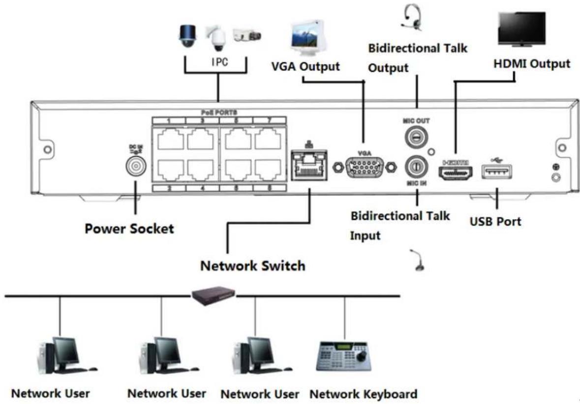
text_image
IPC VGA Output Bidirectional Talk Output HDMI Output PoE PORTB VGA MIC OUT MIC IN NVIDIA USB Port Power Socket Network Switch Network User Network User Network User Network Keyboard3.6.5 NVR22-S2/22-P-S2/22-8P-S2/22-4KS2/22-P-4KS2/22-8P-4KS2 Series
Please refer to Figure 3-5 for connection sample.
The following figure for reference only.
Figure 3-5
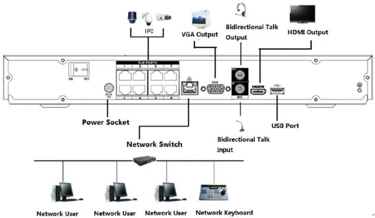
text_image
IPC VGA Output Bidirectional Talk Output HDMI Output ON OFF P&E PORTS 1 3 5 7 DC IN 2 4 6 8 VGA MIC USB Port Power Socket Network Switch Bidirectional Talk Input Network User Network User Network User Network Keyboard3.6.6 NVR42N Series
Please refer to Figure 3-6 for connection sample.
Figure 3-6
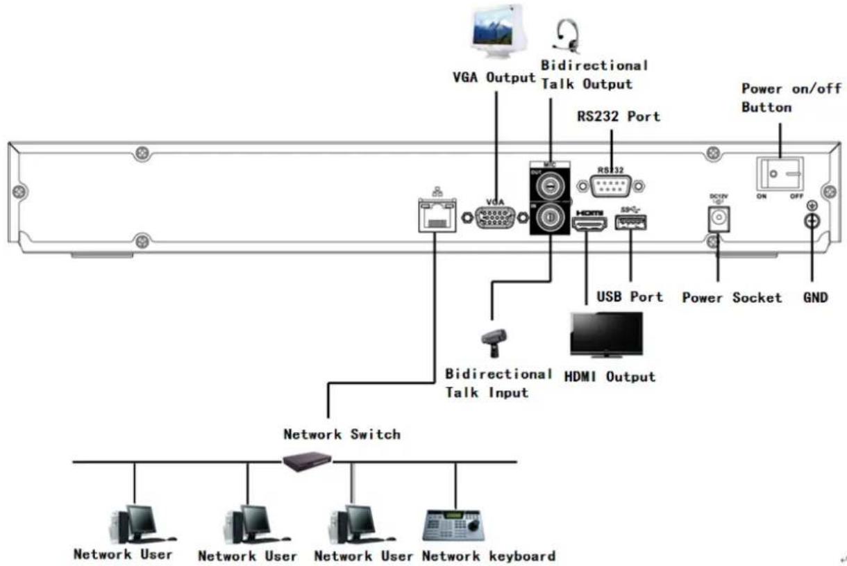
text_image
VGA Output Bidirectional Talk Output RS232 Port Power on/off Button USB Port Power Socket GND Bidirectional Talk Input HDMI Output Network Switch Network User Network User Network User Network keyboard3.6.7 NVR42/42-P/42-8P/42-16P/52-4KS2/52-8P-4KS2/52-16P-4KS2/5224-24P-4KS2/52-8P-4KS2E/52-16P-4KS2E Series
Please refer to Figure 3-7 for connection sample.
The following figure for reference only.
Figure 3-7
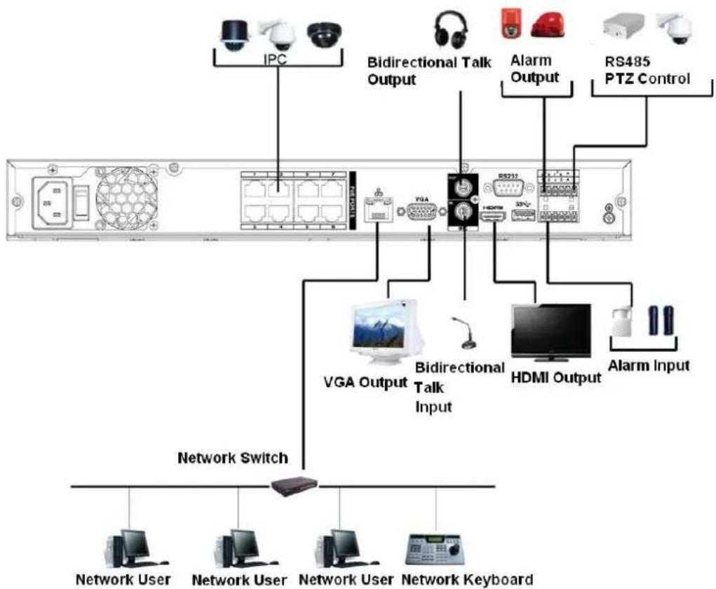
flowchart
graph TD
    A["Network User"] --> B["Network Switch"]
    C["Network Keyboard"] --> B
    D["IPC"] --> E["VGIA"]
    F["Bidirectional Talk Output"] --> E
    G["Alarm Output"] --> H["RS211"]
    I["RS485 PTZ Control"] --> H
    J["VGA Output"] --> K["Bidirectional Talk Input"]
    L["HDMI Output"] --> K
    M["Alarm Input"] --> K
    B --> N["Computer"]
    B --> O["Computer"]
    B --> P["Computer"]
    B --> Q["Computer"]
    B --> R["Computer"]
3.6.8 NVR42-8P-4K/42-4KS2/42-P-4KS2/42-8P-4KS2/42-16P-4KS2 Series
Please refer to Figure 3-8 for connection sample.
The following figure for reference only.
Figure 3-8
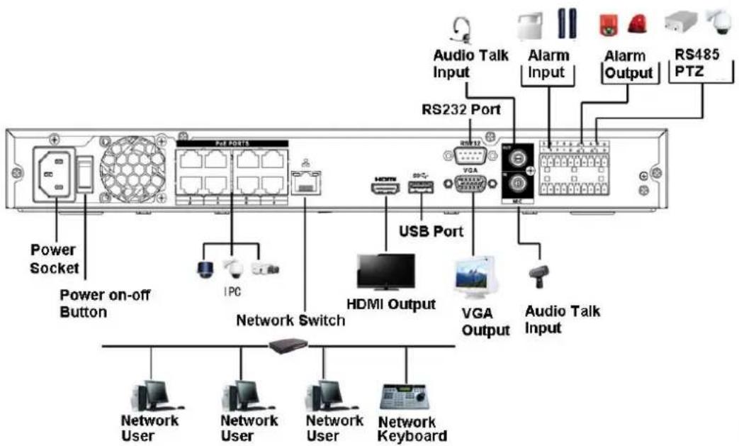
text_image
Power Socket Power on-off Button IPC Network Switch USB Port HDMI Output VGA Output Audio Talk Input RS232 Port VGA Audio Talk Input Alarm Input Alarm Output RS485 PTZ3.6.9 NVR54-4KS2/54-16P-4KS2/58-4KS2/58-16P-4KS2/5424-24P-4KS2/54-16P-4KS2E /5816P-4KS2E Series
Please refer to Figure 3-8 for connection sample.
The following figure for reference only.
Figure 3-9
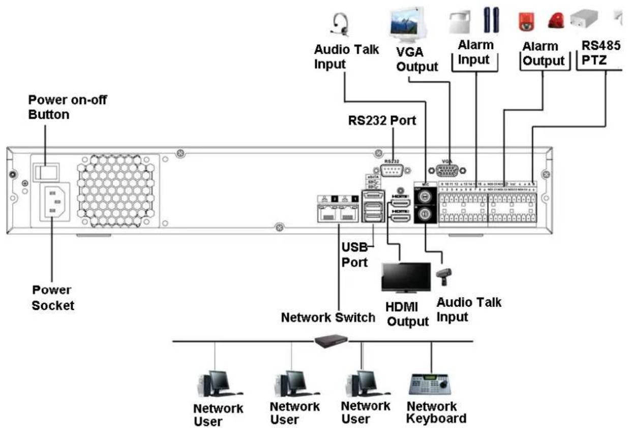
text_image
Power on-off Button Power Socket Audio Talk Input VGA Output RS232 Port USB Port Network Switch HDMI Output Audio Talk Input Network User Network User Network User Network Keyboard3.6.10 NVR44/44-8P/44-16P/44-4KS2/44-16P-4KS2 Series
Please refer to Figure 3-10 for connection sample.
The following figure for reference only.
Figure 3-10
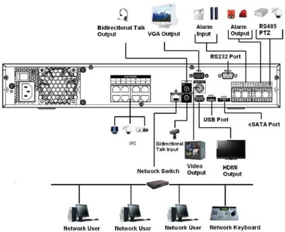
flowchart
graph TD
    A["Back panel with network ports"] --> B["Bidirectional Talk Output"]
    A --> C["VGA Output"]
    A --> D["Alarm Input"]
    A --> E["Alarm Output"]
    A --> F["RS485 PTZ"]
    A --> G["RS232 Port"]
    A --> H["USB Port"]
    A --> I["eSATA Port"]
    A --> J["IPC"]
    A --> K["Bidirectional Talk Input"]
    K --> L["Network Switch"]
    K --> M["Video Output"]
    K --> N["HDMI Output"]
    A --> O["Network User"]
    A --> P["Network User"]
    A --> Q["Network User"]
    A --> R["Network Keyboard"]
3.6.11 NVR48/48-16P/48-4KS2/48-16P-4KS2 Series
Please refer to Figure 3-11 for connection sample.
The following figure for reference only.
Figure 3-11
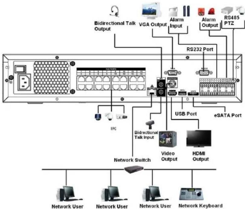
flowchart
graph TD
    A["Network User"] --> B["Network Keyboard"]
    C["Network User"] --> D["Network Keyboard"]
    E["Network Switch"] --> F["Video Output"]
    G["IPC"] --> H["Bidirectional Talk Input"]
    I["RS232 Port"] --> J["USB Port"]
    K["RS485 PTZ"] --> L["eSATA Port"]
    M["Bidirectional Talk Output"] --> N["VGA Output"]
    O["Alarm Input"] --> P["RS232 Port"]
    Q["Alarm Output"] --> R["RS485 PTZ"]
3.6.12 NVR42V-8P Series
Please refer to Figure 3-12 for connection sample.
Figure 3-12
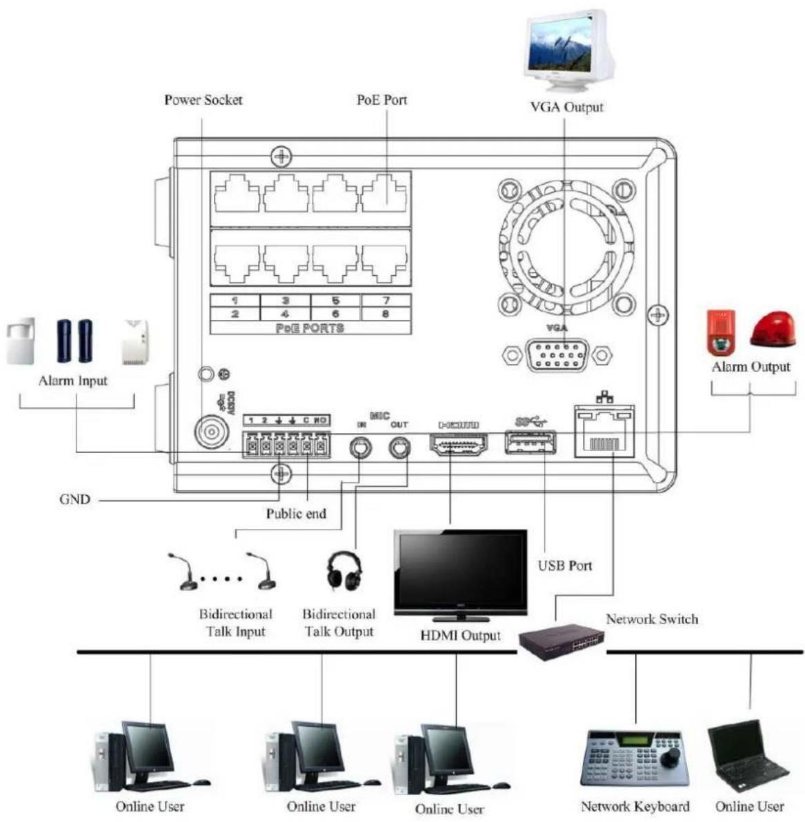
text_image
Power Socket PoE Port VGA Output 1 3 5 7 2 4 6 8 PoE PORTS GND Public end 1 2 ↓ C HD MIC OUT USB Port Bidirectional Talk Input Bidirectional Talk Output HDMI Output Network Switch USB Port Alarm Input Alarm Output Online User Online User Online User Network Keyboard Online User
Slight difference may be found on the user interface. The following figures for reference only.
4.1 Getting Started
This chapter introduces device initial settings such as boot up, device initialization, reset password, and quick settings.
4.1.1 Boot up

- For device security, connect the NVR to the power adapter first and then connect the device to the power socket.
- The rated input voltage matches the device power button. Make sure the power wire connection is OK. Then click the power button.
● Always use the stable current, if necessary UPS is a best alternative measure.
Step 1 Connect the device to the monitor and then connect a mouse.
Step 2 Connect power cable.
Step 3 Click the power button at the front or rear panel and then boot up the device. After device booted up, the system is in multiple-channel display mode by default.
4.1.2 Device Initialization
If it is your first time to use the device, set a login password of admin (system default user). You can select to use unlock pattern to login or not at your own choosing.

For your device safety, keep your login password of admin well after the initialization steps, and change the password regularly.
Step 1 Boot up NVR.
The Device Initialization interface is displayed. See Figure 4-1.
Figure 4-1
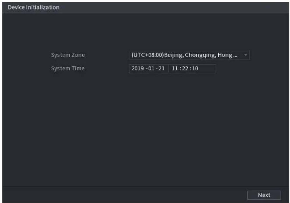
text_image
Device Initialization System Zone (UTC+08:00) Beijing, Chongqing, Hong ... System Time 2019 -01 -21 11 :22 :10 NextStep 2 Set system time zone according to the actual environment. Refer to Table 4-4 in "4.1.4.1.2 Date and Time" for detailed information.

Click to shut down the device. It is suitable for the system integrator or the user to shut down directly after setting the time zone.
Step 3 Click Next.
The Device Initialization interface is displayed. See Figure 4-2.
Figure 4-2
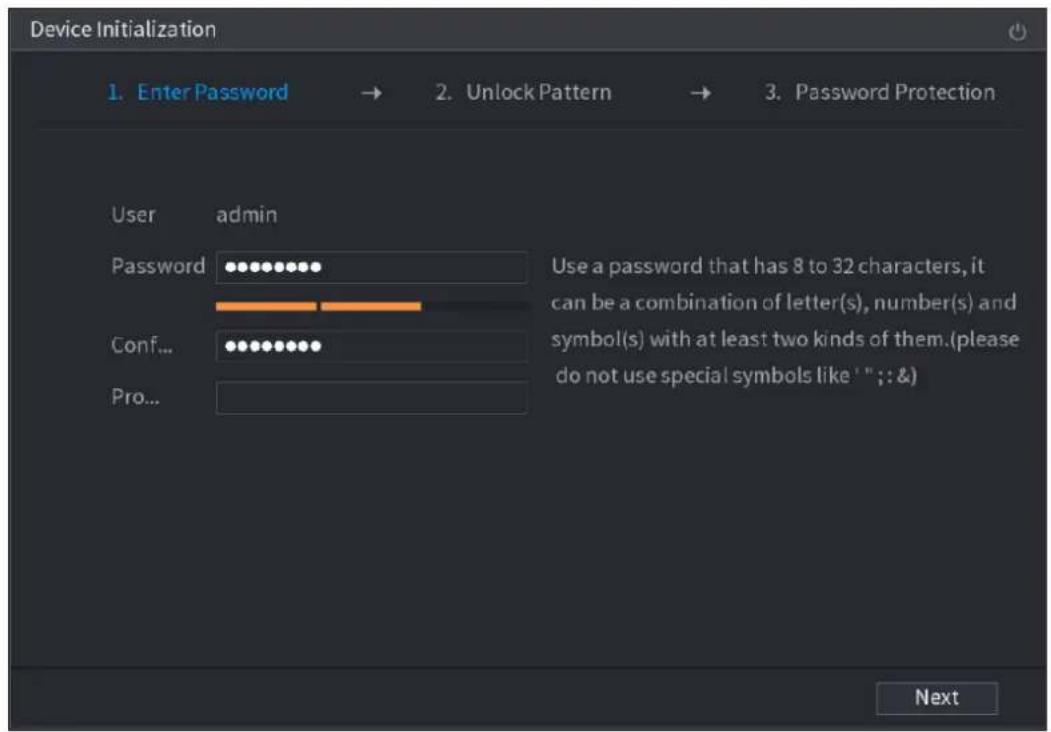
text_image
Device Initialization 1. Enter Password → 2. Unlock Pattern → 3. Password Protection User admin Password Conf... Use a password that has 8 to 32 characters, it can be a combination of letter(s), number(s) and symbol(s) with at least two kinds of them.(please do not use special symbols like ' "; &) Pro... NextStep 4 Set login password of admin. See Table 4-1.
Table 4-1
| Parameter | Description |
| User | By default, the user isadmin. |
| Password | In thePasswordbox, enter the password for admin.The new password can be set from 8 characters through 32 characters and contains at least two types from number, letter and special characters (excluding" "", "", ";", ":" and "&"). |
| Confirm Password | |
| Prompt Question | In thePrompt Questionbox, enter the information that can remind you of the password.On the login interface, click the prompt will display to help you reset the password. |

For your device own safety, create a strong password of your own choosing. We also recommend you change your password periodically especially in the high security system. Step 5 Click Next.
The Unlock Pattern interface is displayed. See Figure 4-3.
Figure 4-3
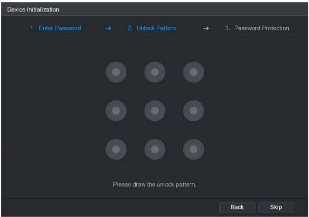
text_image
Device Initialization 1. Enter Password → 2. Unlock Pattern → 3. Password Protection Please draw the unlock pattern. Back SkipStep 6 Set unlock pattern.
After set unlock pattern, the Password Protection interface is displayed. See Figure 4-4.

● The pattern that you want to set must cross at least four grids.
- If you do not want to configure the unlock pattern, click Skip.
- Once you have configured the unlock pattern, the system will require the unlock pattern as the default login method. If you skip this setting, enter the password for login.
Figure 4-4
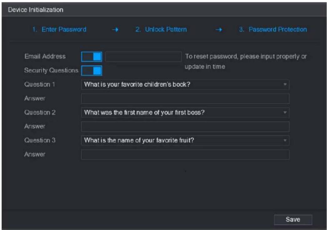
text_image
Device Initialization 1. Enter Password → 2. Unlock Pattern → 3. Password Protection Email Address To reset password, please input properly or Security Questions update in time Question 1 What is your favorite children's book? Answer Question 2 What was the first name of your first boss? Answer Question 3 What is the name of your favorite fruit? Answer SaveStep 7 Set security questions. See Table 4-2.
- After configuration, if you forgot the password for admin user, you can reset the password through the reserved email address or security questions. For details about resetting the password, see "4.1.3 Reset Password".
- If you do not want to configure the settings, disable the email address and security questions functions on the interface.
Table 4-2
| Password Protection Mode | Description |
| Email Address | Enter the reserved email address.In the Email Address box, enter an email address for password reset. If you forget the password, enter the security code that you will get from this reserved email address to reset the password of admin.Refer to " 4.15.1.2 Modify Password" for detailed information. |
| Security Questions | Configure the security questions and answers.If you forget the password, enter the answers to the questions can allow you reset the password. Refer to " 4.15.3 Reset Password " for detailed information. |
Step 8 Click Save to complete the device initialization setup.
Step 9 Device goes to startup wizard interface. Refer to "4.1.4 Quick Settings" for detailed information.
4.1.3 Reset Password
You can reset the password by the following methods when you forgot the password for admin account.
- If the password reset function is enabled, you can use mobile phone to scan the QR code to reset the password. For details, see "4.1.3.2 Resetting Password on Local Interface."
- If the password reset function is disabled, there are two situations:
◇ If you configured security questions, you can reset the password by the security questions.
If you did not configure the security questions, you can only use the reset button on the mainboard to restore the Device to factory default.

Reset button is for some series product only.
4.1.3.1 Enabling Password Reset Function
After enabling password reset function, you can scan QR code on the local menu to reset password.
Step 1 Select Main Menu > Account > Reset Password.
The Reset Password interface is displayed. See Figure 4-5.
Figure 4-5
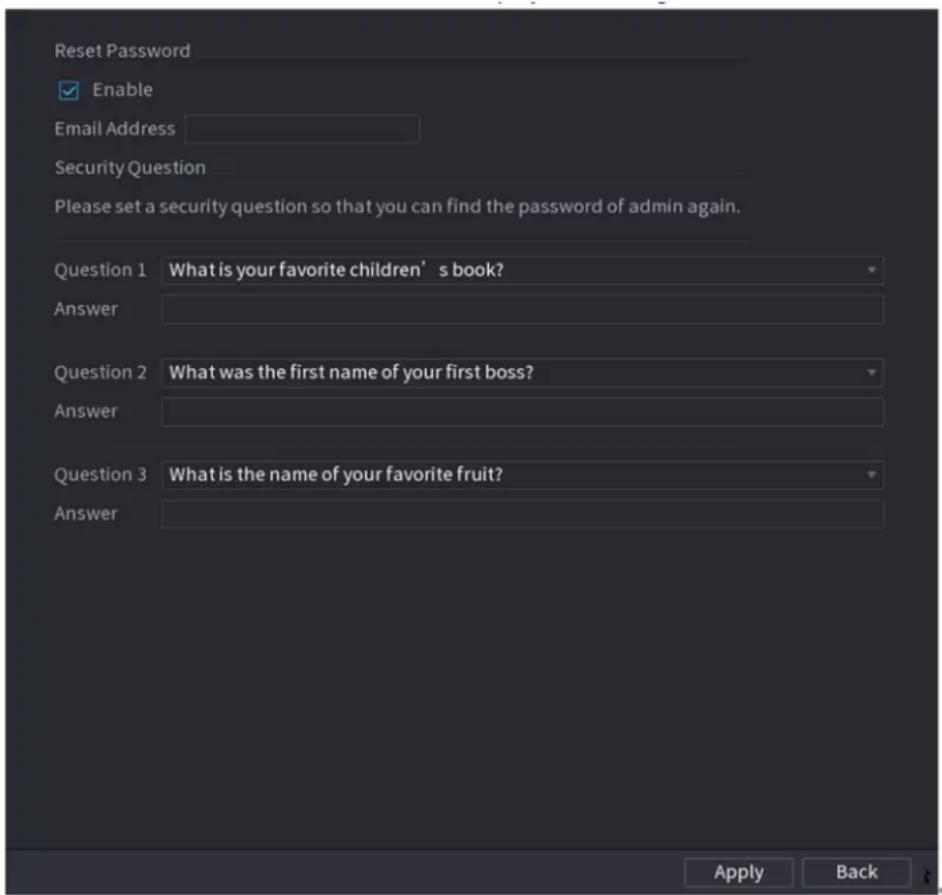
text_image
Reset Password Enable Email Address Security Question Please set a security question so that you can find the password of admin again. Question 1 What is your favorite children' s book? Answer Question 2 What was the first name of your first boss? Answer Question 3 What is the name of your favorite fruit? Answer Apply BackStep 2 Check the box to enable reset function.

This function is enabled by default.
Step 3 Click Apply to set settings.
If the password reset function is disabled, you can follow the ways listed below to reset password.
- Device supports Reset button on the main board: You can answer the security question on the local menu or click the Reset button on the main board to reset password. Refer to "4.1.3.3 Reset Button" for detailed information.
- Device does not support Reset button on the main board: You can only answer the security question on the local menu to reset password. (Make sure you have set security questions).
4.1.3.2 Resetting Password on Local Interface
Step 1 Enter the SYSTEM LOGIN interface.
- If you have configured unlock pattern, the unlock pattern login interface is displayed. See Figure 4-6. Click Forgot Pattern, the password login interface is displayed. See Figure 4-7.
- If you did not configure unlock pattern, the System Login interface is displayed. See Figure 4-7.

To login from other user account, on the unlock pattern login interface, click Switch User, or on the password login interface, in the Switch User list, select other user to login.
Figure 4-6
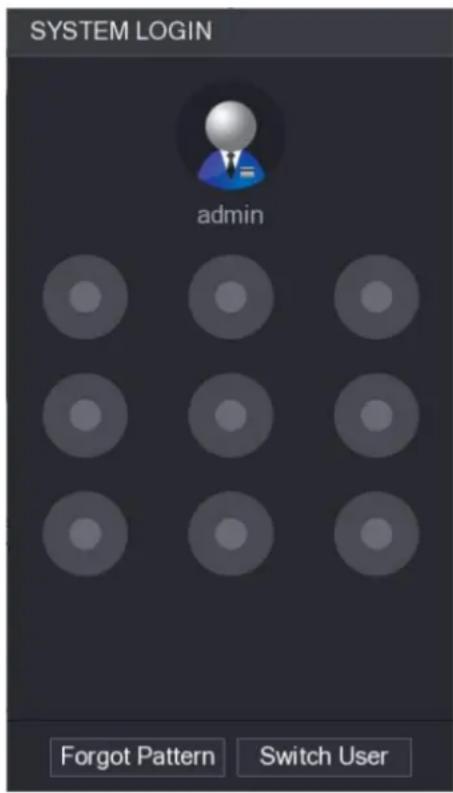
text_image
SYSTEM LOGIN admin Forgot Pattern Switch UserFigure 4-7
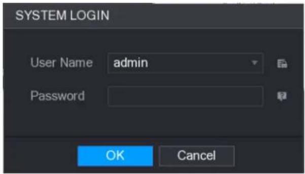
text_image
SYSTEM LOGIN User Name admin Password OK CancelStep 2 Click

- If you have set the reserved email address, the Prompt interface is displayed. See Figure 4-8.
- If you did not set the reserved email address, the email entering interface is displayed. See Figure 4-9.
- Enter the email address, and then click Next, the Prompt message interface is displayed. See Figure 4-8.
Figure 4-8
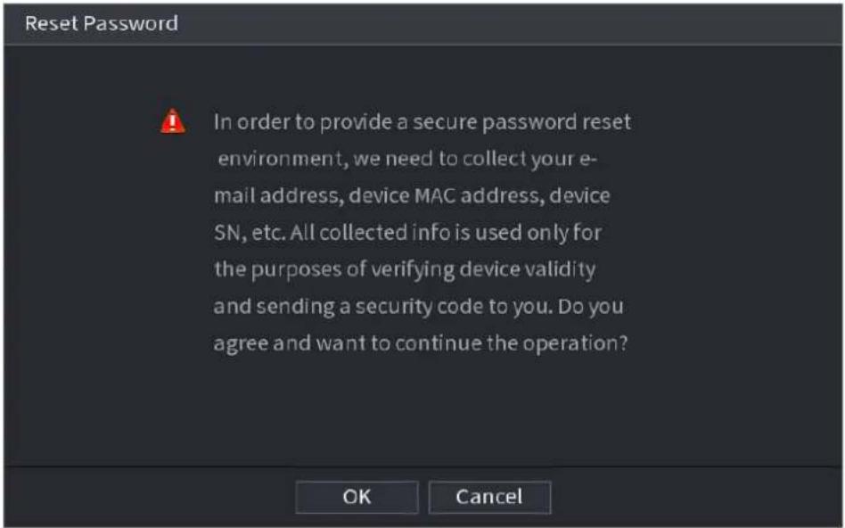
text_image
Reset Password In order to provide a secure password reset environment, we need to collect your e-mail address, device MAC address, device SN, etc. All collected info is used only for the purposes of verifying device validity and sending a security code to you. Do you agree and want to continue the operation? OK CancelFigure 4-9
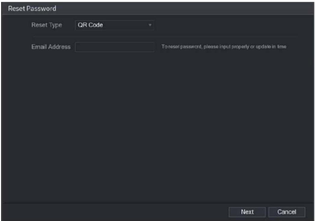
text_image
Reset Password Reset Type QR Code Email Address To reset password, please input properly or update in time Next CancelStep 3 Click Next.
The Reset Password interface is displayed. See Figure 4-10.

After clicking Next, the system will collect your information for password reset, purpose and the information includes but not limited to email address, MAC address, and device serial number. Read the prompt carefully before clicking Next.
Figure 4-10
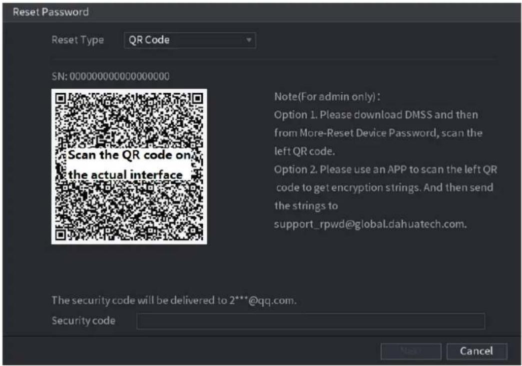
text_image
Reset Password Reset Type QR Code SN: 000000000000000000 Scan the QR code on the actual interface Note(For admin only): Option 1. Please download DMSS and then from More-Reset Device Password, scan the left QR code. Option 2. Please use an APP to scan the left QR code to get encryption strings. And then send the strings to support_rpwd@global.dahuatech.com. The security code will be delivered to 2***@qq.com. Security code Next CancelStep 4 Reset the password.
- QR code
Follow the onscreen instructions to get the security code in your reserved email address. In the Security code box, enter the security code.

- You can get the security code twice by scanning the same QR code. If you need to get the security code once again, refresh the interface.
- Use the security code received in your email box to reset the password within 24 hours; otherwise the security code becomes invalid.
- Security questions
On the Reset password interface as shown in Figure 4-11, in the Reset Type list, select Security Questions, the Security Questions interface is displayed.

If you did not configure the security questions before, in the Reset Type list, there is no Security Questions.
Figure 4-11
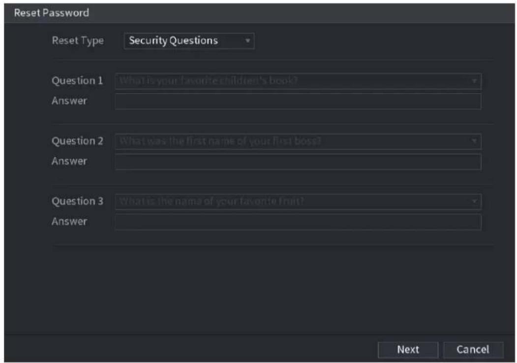
text_image
Reset Password Reset Type Security Questions Question 1 What is your favorite children's book? Answer Question 2 What was the first name of your first boss? Answer Question 3 What is the name of your favorite fruit? Answer Next CancelStep 5 Click Next.
The Reset Password interface is displayed. See Figure 4-12.
Figure 4-12
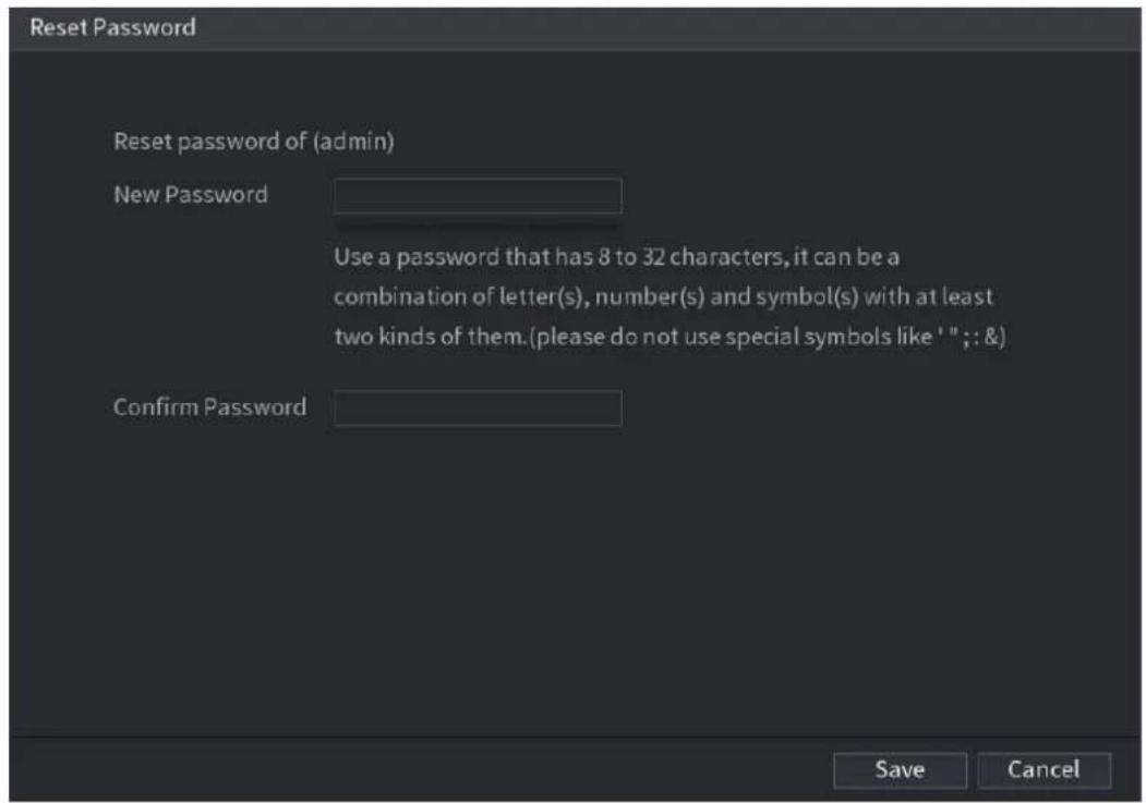
text_image
Reset Password Reset password of (admin) New Password Use a password that has 8 to 32 characters, it can be a combination of letter(s), number(s) and symbol(s) with at least two kinds of them.(please do not use special symbols like ' "; & ) Confirm Password Save CancelStep 6 In the New Password box, enter the new password and enter it again in the Confirm Password box.
Step 7 Click Save. The password resetting is complete.
A pop-up message is displayed asking if you want to sync the password with the remote devices. See Figure 4-13.
Figure 4-13
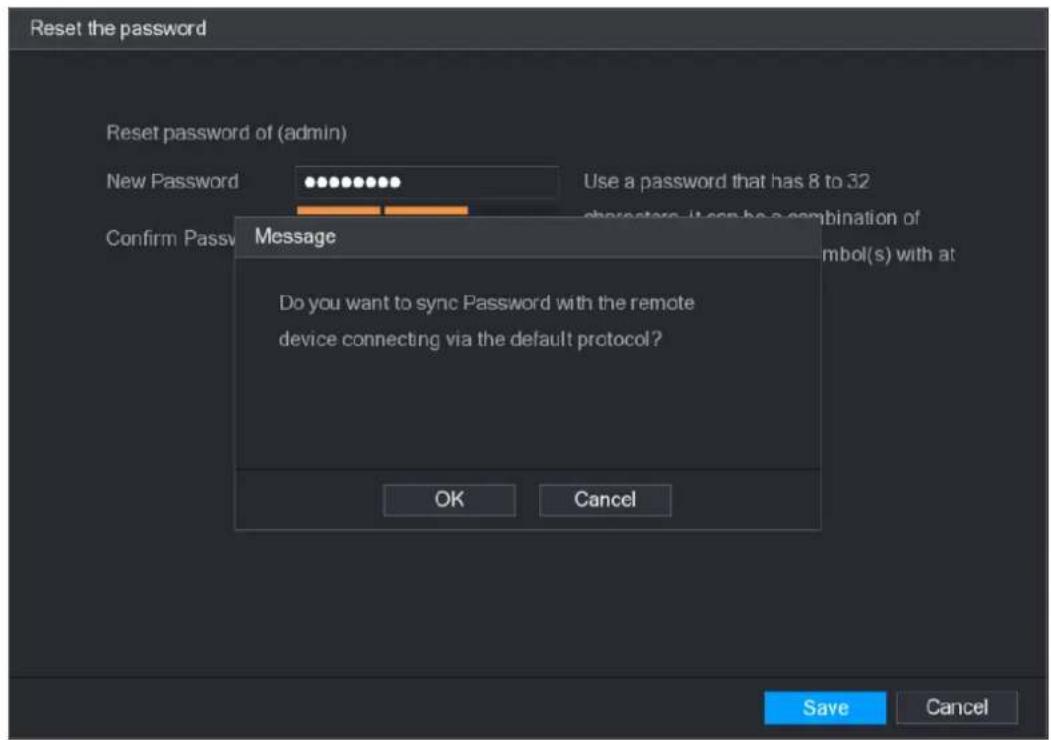
text_image
Reset the password Reset password of (admin) New Password Use a password that has 8 to 32 Confirm Passv Message Do you want to sync Password with the remote device connecting via the default protocol? OK Cancel Save Cancel4.1.3.3 Reset Button
You can always use the reset button on the mainboard to reset the Device to the factory default settings.

Reset button is for some series products only.
Step 1 Disconnect the Device from power source, and then remove the cover panel. For details about removing the cover panel, see "3.4 HDD Installation."
Step 2 Find the reset button on the mainboard, and then connect the Device to the power source again.
Step 3 Press and hold the reset button for 5 seconds to 10 seconds. See Figure 4-14 for the location of the reset button.
Figure 4-14

natural_image
Close-up of a printed circuit board with various electronic components and connectors (no readable text or symbols)Step 4 Reboot the Device.
After the Device is rebooted, the settings have been restored to the factory default. You can start resetting the password.
4.1.4 Quick Settings
After you successfully initialized the device, it goes to startup wizard. Here you can quickly configure your device. Click Next, device goes to General interface.

The startup wizard interface only displays after you first login the device and have set the admin password. See Figure 4-15.
Figure 4-15
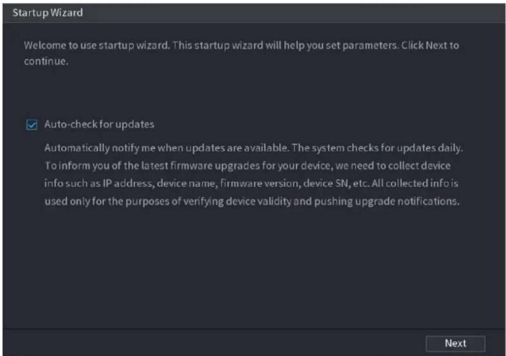
text_image
Startup Wizard Welcome to use startup wizard. This startup wizard will help you set parameters. Click Next to continue. ✓ Auto-check for updates Automatically notify me when updates are available. The system checks for updates daily. To inform you of the latest firmware upgrades for your device, we need to collect device info such as IP address, device name, firmware version, device SN, etc. All collected info is used only for the purposes of verifying device validity and pushing upgrade notifications.
- If you select the Auto-check for updates check box, the system will notify you automatically when updates are available.
- After the auto-check function is enabled, to notify you to update timely, the system will collect the information such as IP address, device name, firmware version, and device serial number. The collected information is only used to verify the legality of the Device and push upgrade notices.
- If you cancel the Auto-check for updates check box, the system will not perform automatic checks.
4.1.4.1 General
You can set NVR basic information such as system date, holiday and etc. You can also configure general settings by selecting Main Menu > SYSTEM > General.
4.1.4.1.1 General
You can set device basic information such as device name, serial number.
Step 1 Click Next.
The General interface is displayed. See Figure 4-16.
Figure 4-16
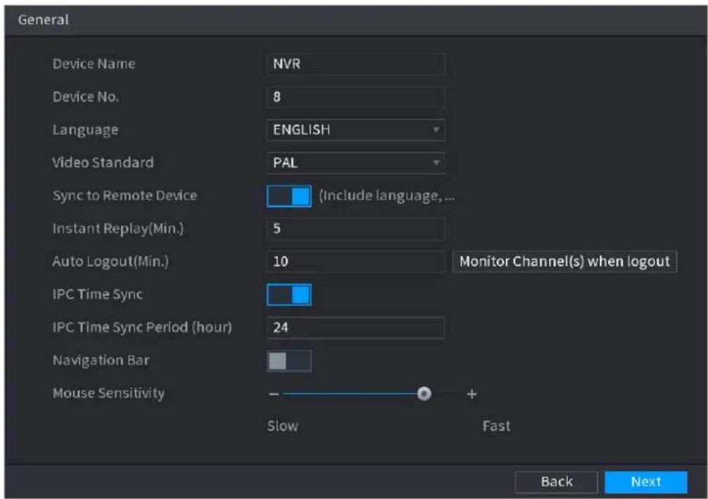
text_image
General Device Name NVR Device No. 8 Language ENGLISH Video Standard PAL Sync to Remote Device (Include language,... Instant Replay(Min.) 5 Auto Logout(Min.) 10 Monitor Channel(s) when logout IPC Time Sync IPC Time Sync Period (hour) 24 Navigation Bar Mouse Sensitivity - Slow + Fast Back NextStep 2 Set parameters. See Table 4-3.
Table 4-3
| Parameter | Description |
| Device Name | In the Device Name box, enter the Device name. |
| Device No. | In the Device No. box, enter a number for the Device. |
| Language | In the Language list, select a language for the Device system. |
| Video Standard | In the Video Standard list, select PAL or NTSC according to your actual situation. |
| Sync to Remote Device | Enable this function; the NVR can synchronize information with the remote device such as Language, video standard, time zone. |
| Instant Play (Min.) | In the Instant Play box, enter the time length for playing back the recorded video. The value ranges from 5 to 60.On the live view control bar, click the instant playback button to play back the recorded video within the configured time. |
| Auto Logout (Min.) | In the Auto Logout box, enter the standby time for the Device. The Device automatically logs out when it is not working for the configured time period. You need to login the Device again.The value ranges from 0 to 60. 0 indicates there is not standby time for the Device.Click Monitor Channel(s) when logout. You can select the channels that you want to continue monitoring when you logged out. |
| IPC Time Sync | Syncs the Device time with IP camera. |
| IPC Time Sync Period (hour) | In the IPC Time Sync Period box, enter the interval for time sync. |
| Auto logout | You can set auto logout interval once login user remains inactive for a specified time. Value ranges from 0 to 60 minutes. |
| Navigation Bar | Enable the navigation bar. When you click on the live view screen, the navigation bar is displayed. |
| Mouse Sensitivity | Adjust the speed of double-click by moving the slider.The bigger the value is, the faster the speed is. |
Step 3 Click Next button to save settings.
4.1.4.1.2 Date and Time
You can set device time. You can enable NTP (Network Time Protocol) function so that the device can sync time with the NTP server.
You can also configure date and time settings by selecting Main Menu > SYSTEM > GENERAL > Date&Time.
Step 1 Click Date & Tim tab. See Figure 4-17.
Figure 4-17
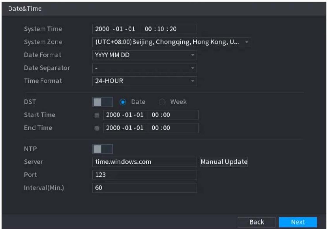
text_image
Date&Time System Time 2000 -01 -01 00 :10 :20 System Zone (UTC+08:00) Beijing, Chongqing, Hong Kong, U... Date Format YYYY MM DD Date Separator - Time Format 24-HOUR DST Date Week Start Time 2000 -01 -01 00 :00 End Time 2000 -01 -01 00 :00 NTP Server time.windows.com Manual Update Port 123 Interval(Min.) 60 Back NextStep 2 Configure the settings for date and time parameters. See Table 4-4.
Table 4-4
| Parameter | Description |
| System Time | In the System Time box, enter time for the system.Click the time zone list, you can select a time zone for the system, and the time in adjust automatically. Do not change the system time randomly; otherwise the recorded video cannot be searched. It is recommended to avoid the recording period or stop recording first before you change the system time. Do not change the system time randomly; otherwise the recorded video cannot be searched. It is recommended to avoid the recording period or stop recording first before you change the system time. |
| System Zone | In the System Zone list, select a time zone for the system. |
| Date Format | In the Date Format list, select a date format for the system. |
| Date Separator | In the Date Separator list, select a separator style for the date. |
| Time Format | In the Time Format list, select 12-HOUR or 24-HOUR for the time display style. |
| DST | Enable the Daylight Saving Time function. Click Week or click Date. |
| Start Time | Configure the start time and end time for the DST. |
| End Time | |
| NTP | Enable the NTP function to sync the Device time with the NTP server. |
| Server | In the Server box, enter the IP address or domain name of the corresponding NTP server.Click Manual Update, the Device starts syncing with the server immediately. |
| Port | The system supports TCP protocol only and the default setting is 123. |
| Interval (Min.) | In the Interval box, enter the amount of time that you want the Device to sync time with the NTP server. The value ranges from 0 to 65535. |
Step 3 Click Next button to save settings.
4.1.4.1.3 Holiday
Here you can add, edit, delete holiday. After you successfully set holiday information, you can view holiday item on the record and snapshot period.
You can also configure holiday settings by selecting Main Menu > SYSTEM > GENERAL > Holiday.
Step 1 Click Next.
The Holiday interface is displayed. See Figure 4-18.
Figure 4-18
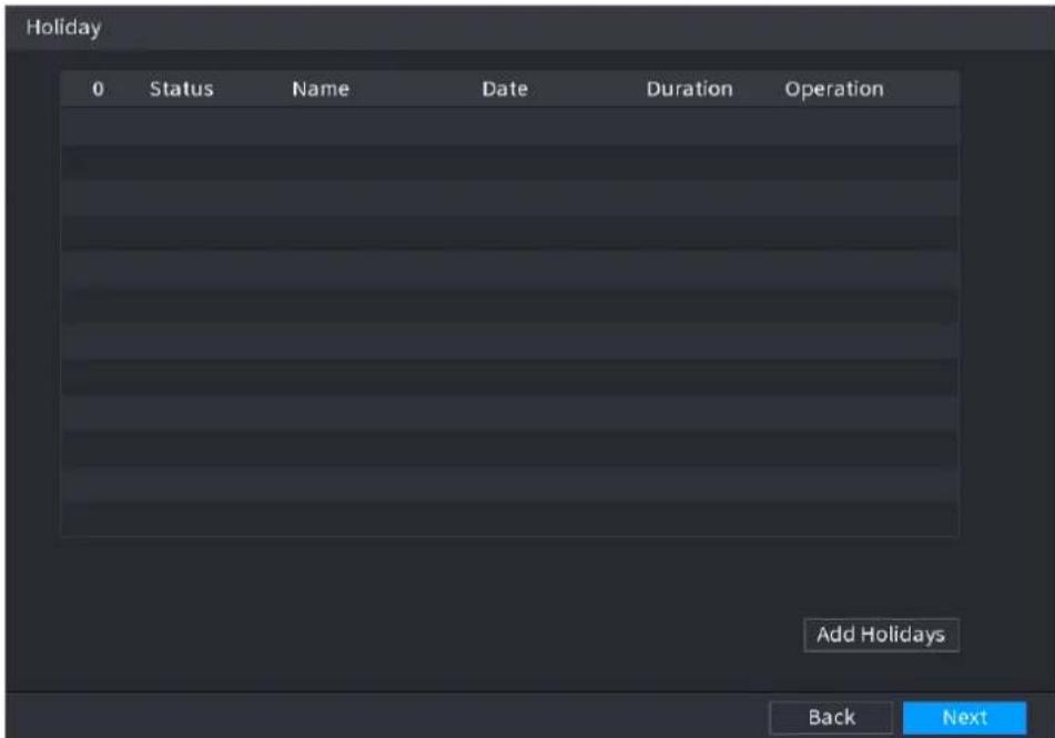
text_image
Holiday 0 Status Name Date Duration Operation Add Holidays Back NextStep 2 Click Add Holidays button, the Add Holidays interface is displayed. See Figure 4-19.
Figure 4-19
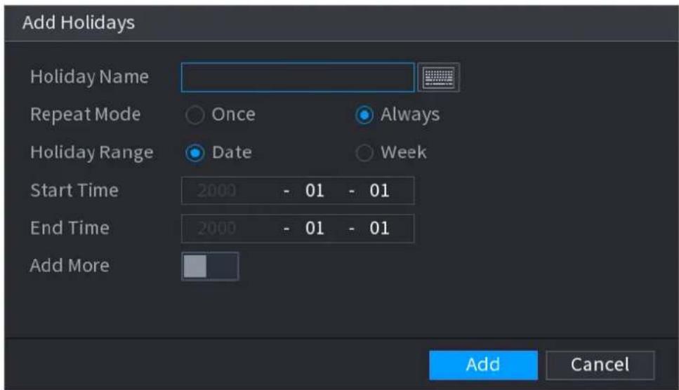
text_image
Add Holidays Holiday Name Repeat Mode Once Always Holiday Range Date Week Start Time 2000 - 01 - 01 End Time 2000 - 01 - 01 Add More Add CancelStep 3 Set holiday name, repeat mode and holiday mode.

Click Add more to add new holiday information.
Step 4 Click Add button, you can add current holiday to the list.

- Click the dropdown list of the state; you can enable/disable holiday date.
- Click to change the holiday information. Click to delete current date.
Step 5 Click Next button to save settings.
4.1.4.2 Basic Network Settings
You can set device IP address, DNS (Domain Name System) information. You can also configure basic network settings by selecting Main Menu > NETWORK > TCP/IP.
Preparation
Make sure the device has properly connected to the network.
Step 1 Click Next.
The TCP/IP interface is displayed. See Figure 4-20.

Different series products have different Ethernet adapter amount and type. Refer to the actual product.
Figure 4-20
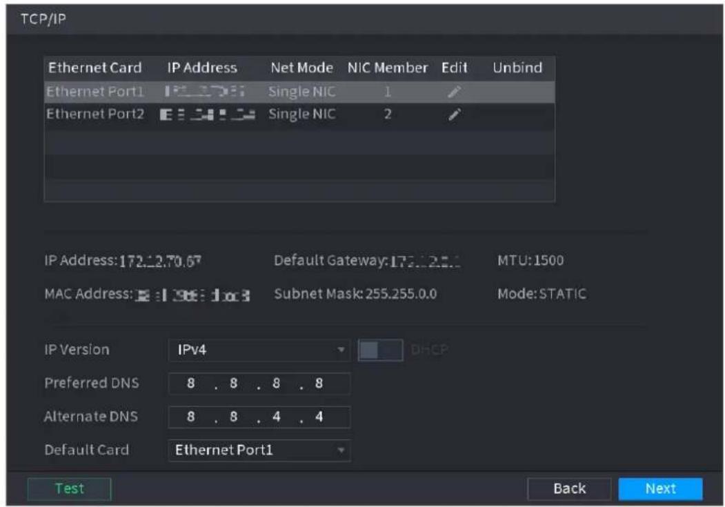
text_image
TCP/IP Ethernet Card IP Address Net Mode NIC Member Edit Unbind Ethernet Port1 IP 1706 Single NIC 1 Ethernet Port2 IP 1706 Single NIC 2 IP Address:172.12.70.67 Default Gateway:173.12.81 MTU:1500 MAC Address: IP 198.10x3 Subnet Mask:255.255.0.0 Mode:STATIC IP Version IPv4 Preferred DNS 8 . 8 . 8 . 8 Alternate DNS 8 . 8 . 4 . 4 Default Card Ethernet Port1 Test Back NextStep 2 Click

The Edit interface is displayed. See Figure 4-21.
Figure 4-21
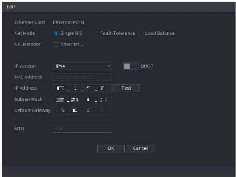
text_image
Edit Ethernet Card Ethernet Port1 Net Mode Single NIC Fault-ToleranceLoad Balance NIC Member Ethernet... IP Version IPv4 DHCP MAC Address 366728.00.00 IP Address Test Subnet Mask Default Gateway MTU 5900 OK CancelStep 3 Set parameters. See Table 4-5.
Step 4 Click OK to NIC settings.
Device goes back to TCP/IP interface.
Table 4-5
Step 5 Set network parameters. See Table 4-6.
| Parameter | Description |
| Net Mode | Multi-address: Two Ethernet ports work separately through either of which you can request the Device to provide the services such as HTTP and RTSP. You need to configure a default Ethernet port (usually the Ethernet port 1 by default) to request the services from the device end such as DHCP, Email and FTP. If one of the two Ethernet ports is disconnected as detected by networking testing, the system network status is regarded as offline.Fault Tolerance: Two Ethernet ports share one IP address. Normally only one Ethernet port is working and when this port fails, the other port will start working automatically to ensure the network connection.When testing the network status, the network is regarded as offline only when both of the two Ethernet ports are disconnected. The two Ethernet ports are used under the same LAN.Load Balance: Two network cards share one IP address and they are working at the same time to share the network load averagely. If one of them fails, the other can continue working normally.When testing the network status, the network is regarded as offline only when both of the two Ethernet ports are disconnected. The two Ethernet ports are used under the same LAN.The Device with single Ethernet port does not support this function. |
| Default Ethernet Port | In the Ethernet Card list, select an Ethernet port as a default port.This setting is available only when the Multi-address is selected in the Net Mode list. |
| IP Version | In the IP Version list, you can select IPv4 or IPv6. Both versions are supported for access. |
| MAC Address | Displays the MAC address of the Device. |
| DHCP | Enable the DHCP function. The IP address, subnet mask and default gateway are not available for configuration once DHCP is enabled.If DHCP is effective, the obtained information will display in the IP Address box, Subnet Mask box and Default Gateway box. If not, all values show 0.0.0.0.If you want manually configure the IP information, disable the DHCP function first.If PPPoE connection is successful, the IP address, subnet mask, default gateway, and DHCP are not available for configuration. |
| IP Address | Enter the IP address and configure the corresponding subnet mask and default gateway. |
| Subnet Mask | |
| Default Gateway | IP address and default gateway must be in the same network segment. |
| DNS DHCP | Enable the DHCP function to get the DNS address from router. |
| Preferred DNS | In the Preferred DNS box, enter the IP address of DNS. |
| Alternate DNS | In the Alternate DNS box, enter the IP address of alternate DNS. |
| MTU | In the MTU box, enter a value for network card. The value ranges from 1280 byte through 1500 byte. The default is 1500. |
| Test | Click Test to test if the entered IP address and gateway are interworking. |
Table 4-6
| Parameter | Description |
| IP Version | There are two options: IPv4 and IPv6. Right now, system supports these two IP address format and you can access via them. |
| Preferred DNS server | DNS server IP address. |
| Alternate DNS server | DNS server alternate address. |
| MAC Address | Displays the MAC address of the Device. |
| DHCP | Enable the DHCP function. The IP address, subnet mask and default gateway are not available for configuration once DHCP is enabled.If DHCP is effective, the obtained information will display in theIPAddressbox,Subnet Maskbox andDefault Gatewaybox. If not, all values show 0.0.0.0.If you want manually configure the IP information, disable the DHCP function first.If PPPoE connection is successful, the IP address, subnet mask, default gateway, and DHCP are not available for configuration. |
| LAN download | System can process the downloaded data first if you enable this function. The download speed is 1.5X or 2.0X of the normal speed.For IPv6 version, the IP address, default gateway, preferred DNS; alternate DNS is 128-digit. Fill in all items here.This function is for some series product only. |
Step 6 Click Next to complete the settings.
4.1.4.3 P2P
Scan the QR code, download the App to the cell phone, you can use the smart phone to add the device.
- Scan the QR code on the actual interface to download the cell phone app. Register an account and then use.
- Go to the www.easy4ip.com to register an account and use the SN to add a device. Refer to the P2P operation manual for detailed information.

Before use the P2P function, make sure the NVR has connected to the WAN.
Step 1 Click Next button.
The P2P interface is displayed. See Figure 4-22.

Select Main Menu > Network > P2P, you can go to P2P interface too.
Figure 4-22
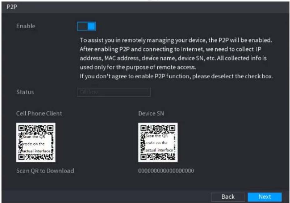
text_image
P2P Enable To assist you in remotely managing your device, the P2P will be enabled. After enabling P2P and connecting to Internet, we need to collect IP address, MAC address, device name, device SN, etc. All collected info is used only for the purpose of remote access. If you don't agree to enable P2P function, please deselect the check box. Status Off-line Cell Phone Client Scan the QR code on the actual interface Device SN Scan the QR code on the actual interface Scan QR to Download 000000000000000000 Back NextStep 2 Check the box to enable P2P function.

After the P2P function is enabled and connected to the Internet, the system will collects your information for remote access, and the information includes but not limited to email address, MAC address, and device serial number.
Step 3 Click Next button to complete setup.
The status is online if the P2P registration is successful.
Client Operation
Step 1 Use your cell phone to scan the QR code under Cell Phone Client to download the application.
Step 2 On your cell phone, open the application, and then tap

Step 3 The menu is displayed. You can start adding the device.
1) Tap Device Manager.
The Device Manager interface is displayed. See Figure 4-23.
Figure 4-23
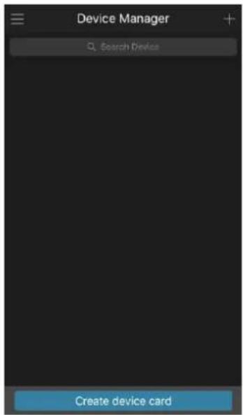
text_image
Device Manager Search Device Create device card2) Tap on the top right corner.
The interface requiring device initialization is displayed. A pop-up message reminding you to make sure the Device is initialized is displayed.
3) Tap OK.
If the Device has not been initialized, Tap Device Initialization to perform initializing by following the onscreen instructions.
◇ If the Device has been initialized, you can start adding it directly.
4) Tap Add Device.
The Add Device interface is displayed. See Figure 4-24.

You can add wireless device or wired device. The Manual takes adding wired device as an example.
Figure 4-24
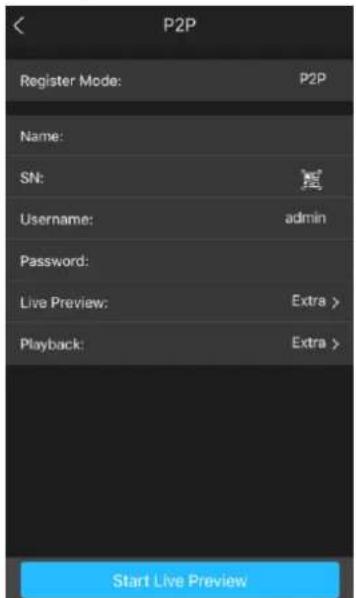
text_image
P2P Register Mode: P2P Name: SN: Username: admin Password: Live Preview: Extra > Playback: Extra > Start Live Preview5) Tap P2P.
The P2P interface is displayed. See Figure 4-25.
Figure 4-25
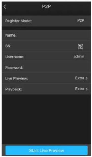
text_image
P2P Register Mode: P2P Name: SN: Username: admin Password: Live Preview: Extra > Playback: Extra > Start Live Preview6) Enter a name for the NVR, the username and password, scan the QR code under Device SN.
7) Tap Start Live Preview.
The Device is added and displayed on the live view interface of the cell phone. See Figure 4-26.
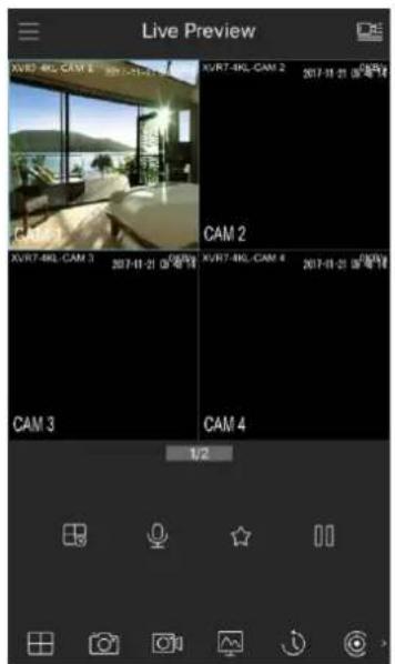
text_image
Live Preview XUR7-4KL-CAM 1 XUR7-4KL-CAM 2 2017-18-21 09:00:18 CAM 1 CAM 2 XUR7-4KL-CAM 3 2017-18-21 09:00:18 CAM 3 CAM 4 1/2Figure 4-26
4.1.4.4 Registration

If you do not select Smart add function during the initialization process, go to the remote Device interface to register a remote device.
After adding remote device, the device can receive, store, and manage the video streams of the remote device. You can view, browse, play back and manage several remote devices at the same time.
Step 1 On the P2P interface, click Next button.
The REGISTRATION interface is displayed. See Figure 4-27.

There are two ways to go to Registration interface.
- Select Main Menu > CAMERA > REGISTRATION > Camera Registration, you can go to the Camera Registration interface.
- On the preview interface, right click mouse and then select Camera Registration.
Figure 4-27
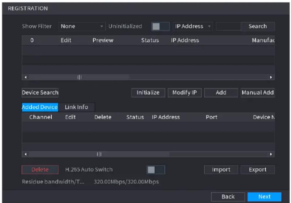
text_image
REGISTRATION Show Filter None Uninitialized IP Address Search 0 Edit Preview Status IP Address Manufac Device Search Initialize Modify IP Add Manual Add Added Device Link Info Channel Edit Delete Status IP Address Port Device N Delete H.265 Auto Switch Import Export Residue bandwidth/T... 320.00Mbps/320.00Mbps Back NextStep 2 Register remote device.
- Search and then add
1) Click Device Search.
System displays searched devices at the upper pane.
2) Double-click a remote device, or select a remote device and then click Add to register it to the Added Device list. See Figure 4-28. Refer to
3) Table 4-7 to set parameters.

The search results do not display the remote camera that has registered to the system
Figure 4-28
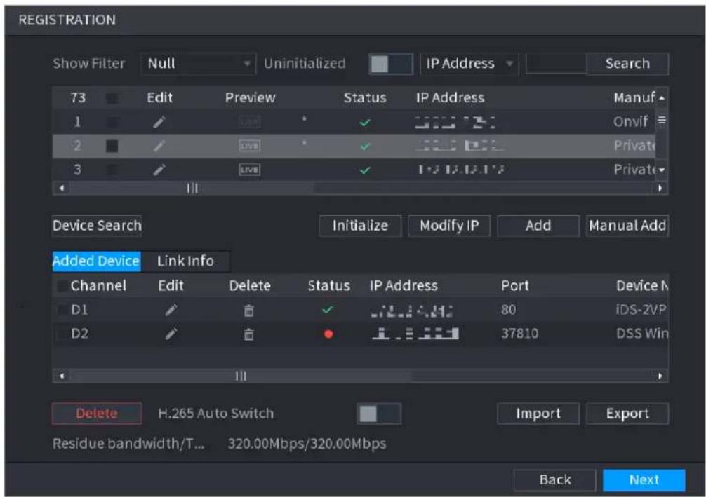
text_image
REGISTRATION Show Filter Null Uninitialized IP Address Search 73 Edit Preview Status IP Address Manuf 1 Onvif 2 Private 3 Private Device Search Initialize Modify IP Add Manual Add Added Device Link Info Channel Edit Delete Status IP Address Port Device N D1 80 iDS-2VP D2 37810 DSS Win Delete H.265 Auto Switch Import Export Residue bandwidth/T... 320.00Mbps/320.00Mbps Back NextTable 4-7
| Parameter | Description |
| Uninitialized | Enable theUninitializedfunction, the uninitialized devices out of the searched devices are displayed in the searched device list. |
| Initialize | Select the uninitialized device from the uninitialized device list, and the clickInitializeto start initializing device. |
| Show Filter | In theShow Filterlist, select the remote device type that you want to display in the searched device list.None: Display all types of devices.IPC: Display the front-end devices.DVR: Display all storage devices such as NVR, DVR and HCVR.OTHER: Display the devices that do not belong to IPC or DVRType. |
| Searched Device List | Displays the searched devices. You can view the device information such as status, IP address. |
| Device Search | ClickDevice Search, the searched devices display in the searched device list.To adjust the display sequence, in the title line, you can click the IP address, Manufacturer, Type, MAC Address, Port, or Device Name text. For example, click the IP address text, the sequence iconIPAdrsplayed.""* is displayed next to the added device. |
| Add | In the Searched Device List area, select the device that you want to add. |
| Manual Add | Add the device by manually configuring settings such as IP address, channel selection. |
| Added Device List | Displays the added devices. You can edit and delete the device, and view the device information. |
| Delete | Select the check box of the added device, and then click Delete to delete the added device. |
| Import | Select the searched devices and then click Import to import the devices in batches. |
| Export | Select the added devices and then click Export. The exported devices information is saved into the USB storage device. |
- Manual Add
1) Click Manual Add.
The Manual Add interface is displayed. See Figure 4-29.
Figure 4-29
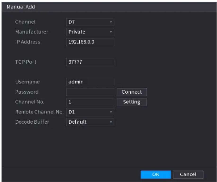
text_image
Manual Add Channel D7 Manufacturer Private IP Address 192.168.0.0 TCP Port 37777 Username adults Password Connect Channel No. 1 Setting Remote Channel No. D1 Decode Buffer Default OK Cancel2) Configure parameters. See Table 4-8.
3) Click OK.
The remote device information is displayed on the Added Device list.
Table 4-8
| Parameter | Description |
| Channel | In the Channel list, select the channel that you want use on the Device to connect the remote device. |
| Manufacturer | In the Manufacturer list, select the manufacturer of the remote device. |
| IP Address | In the IP Address box, enter the IP address of remote device.The default is 192.168.0.0 which the system cannot connect to. |
| RTSP Port | The default value setting is 554. You can enter the value according to your actual situation. |
| HTTP Port | The default value setting is 80. You can enter the value according to your actual situation.If you enter other value, for example, 70, and then you should enter 70 after the IP address when logging in the Device by browser. |
| User Name | Enter the user name of the remote device. |
| Password | Enter the password of the user for the remote device. |
| Remote Channel | Enter the remote channel number of the remote device that you want to add. |
| Decoder Buffer | In the Decoder Buffer list, select Default, Realtime, or Fluent. |
| Protocol Type | If the remote device is added through private protocol, the default type is TCP.If the remote device is added through Onvif protocol, the system supports Auto, TCP, UDP, or MULTICAST.If the remote device is added through other manufacturers, the system supports TCP and UDP. |
| Encrypt | If the remote device is added through Onvif protocol, selecting the Encrypt check box will provide encryption protection to the data being transmitted.To use this function, the HTTPS function should be enabled for the remote IP camera. |
Step 4 Click Next to complete the remote device registration.


to delete remote device.
Once the multiple-sensor device has registered to the device system displays the channel status on the Link info. See Figure 4-30. It shows one remote device has occupied two channels: D1, D3.
Figure 4-30
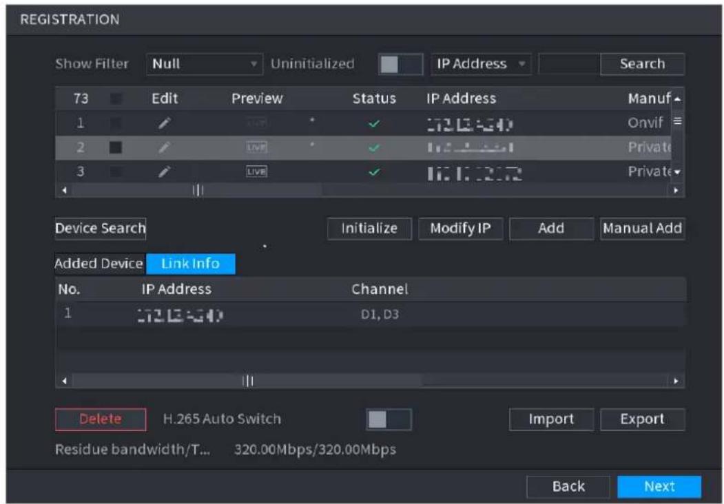
text_image
REGISTRATION Show Filter Null Uninitialized IP Address Search 73 Edit Preview Status IP Address Manuf 1 Onvif 2 LIVE Private 3 LIVE Private Device Search Initialize Modify IP Add Manual Add Added Device Link Info No. IP Address Channel 1 D1, D3 Delete H.265 Auto Switch Import Export Residue bandwidth/T... 320.00Mbps/320.00Mbps Back Next4.1.4.5 RAID Manager
RAID (redundant array of independent disks) is a data storage virtualization technology that combines multiple physical HDD components into a single logical unit for the purposes of data redundancy, performance improvement, or both.

RAID function is for some series product only. Slight difference may be found on the user interface.
Step 1 Select Main Menu > STORAGE > RAID > RAID.
The RAID interface is displayed. See Figure 4-31.
Figure 4-31
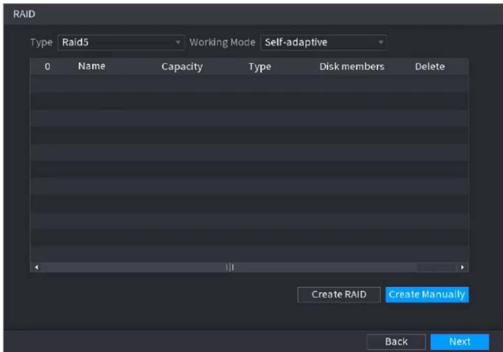
text_image
RAID Type Raid5 Working Mode Self-adaptive 0 Name Capacity Type Disk members Delete Create RAID Create Manually Back NextStep 2 You can click Create RAID or Create Manually, and all the disks involved will be formatted.
- Click Create RAID, the system will create RAID automatically.
If there is no existing RAID and no hot spare disk, the system will create RAID5 and a hot spare disk automatically.
If there is no existing RAID, but existing hot spare disk, the system will only create RAID5 and use the existing hot spare disk automatically.
If there is existing RAID and existing hot spare disk, the system will delete the original RAID and create RAID5 with all the disks and use the existing hot spare disk automatically.
- Click Create Manually.
1) Select RAID type and disks as system instructed.
2) Click Create Manually, and then the format disk notice is displayed.
3) Click OK.
Step 3 After creating RAID, the disks need to sync with each other to finish the process. For RAID5 and RAID6, you can select different working mode.
- Self-Adaptive: Automatically adjust the RAID sync speed according to the business status.
When there is no business running, sync is performed at a high speed.
When there is business running, sync is performed at a low speed.
- Sync First: Resource priority is assigned to RAID sync.
• Business First: Resource priority is assigned to business operations.
• Balance: Resource is evenly distributed to RAID sync and business operations.
4.1.4.6 Schedule
After set record schedule and snapshot schedule, the device can automatically record video and snapshot image at the specified time. Select Main menu > STORAGE > SCHEDULE, you can go to the SCHEDULE interface.
4.1.4.6.1 Recording Schedule
After set schedule record, device can record video file according to the period you set here. For example, the alarm record period is from 6:00–18:00 Monday, device can record alarm video files during the 6:00–18:00.
All channels are record continuously by default. You can set customized record period and record type.
Step 1 Click Next button.
The Rec interface is displayed. See Figure 4-32.
Figure 4-32
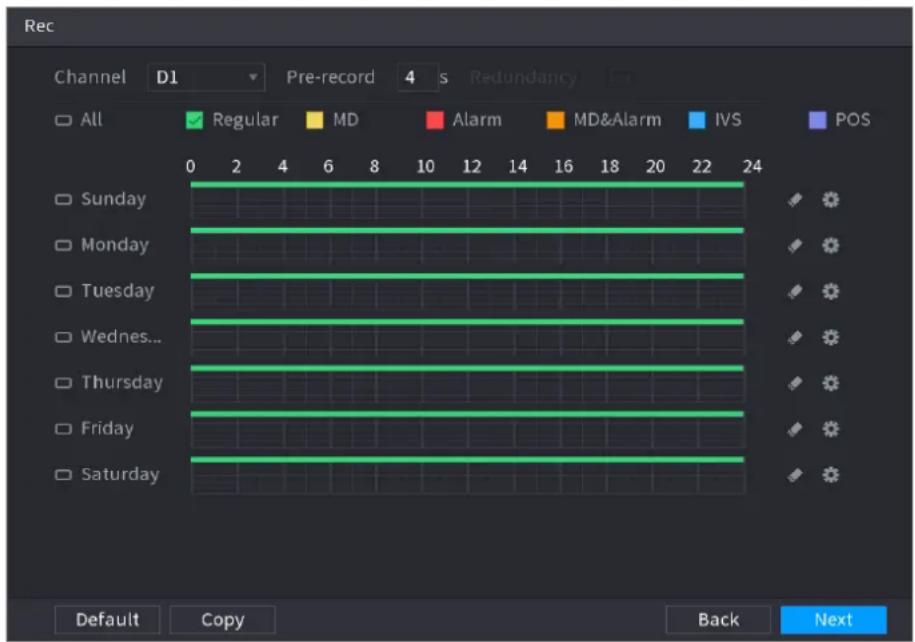
text_image
Rec Channel D1 Pre-record 4 s Redundancy All Regular MD Alarm MD&Alarm IVS POS 0 2 4 6 8 10 12 14 16 18 20 22 Sunday Monday Tuesday Wednesday... Thursday Friday Saturday Default Copy Back NextStep 2 Select a channel from the dropdown list, you can set different record plans for different channels. Select All if you want to set for all channels. See Table 4-9.
Table 4-9
| Parameter | Description |
| Channel | In the Channel list, select a channel to record the video. |
| Pre-record | In the Pre-record list, enter the amount of time that you want to start the recording in advance. |
| Redundancy | If there are several HDDs installed to the Device, you can set one of the HDDs as the redundant HDD to save the recorded files into different HDDs. In case one of the HDDs is damaged, you can find the backup in the other HDD.Select Main Menu > STORAGE > HDD MANAGER, and then set a HDD as redundant HDD.Select Main Menu > STORAGE > SCHEDULE > Record, and then select the Redundancy check box.◇ If the selected channel is not recording, the redundancy function takes effect next time you record no matter you select the checkbox or not.◇ If the selected channel is recording, the current recorded files will be packed, and then start recording according to the new schedule. ● This function is for some series products only.● The redundant HDD only back up the recorded videos but not snapshots. ● This function is for some series products only.● The redundant HDD only back up the recorded videos but not snapshots. |
| ANR | You can set ANR (auto network resume) function.● The IPC continues record once the NVR and IPC connection fails. After the network becomes normal, the NVR can download record file during the offline period from the IPC. It is to guarantee there is no record loss on current connected IPC channel.● Set the max. record upload period. Once the offline period is longer than the period you set here, IPC can only upload the record file during the specified period. This function is for IPC that installed SD card and the record function is enabled. This function is for IPC that installed SD card and the record function is enabled. |
| Period | Define a period during which the configured recording setting is active. See Figure 4-33. The system only activates the alarm in the defined period. The system only activates the alarm in the defined period. |
| Copy | Click Copy to copy the settings to other channels. |
Figure 4-33
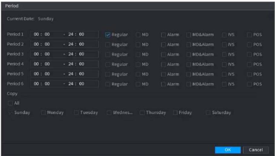
text_image
Period Current Date: Sunday Period 1 00 : 00 - 24 : 00 Regular MD Alarm MD&Alarm IVS POS Period 2 00 : 00 - 24 : 00 Regular MD Alarm MD&Alarm IVS POS Period 3 00 : 00 - 24 : 00 Regular MD Alarm MD&Alarm IVS POS Period 4 00 : 00 - 24 : 00 Regular MD Alarm MD&Alarm IVS POS Period 5 00 : 00 - 24 : 00 Regular MD Alarm MD&Alarm IVS POS Period 6 00 : 00 - 24 : 00 Regular MD Alarm MD&Alarm IVS POS Copy All Sunday Monday Tuesday Wednes Thursday Friday Saturday OK CancelStep 3 Set record type. See Figure 4-34.
Figure 4-34

text_image
All Regular MD Alarm MD&Alarm IVS POS
- When the record type is MD (motion detect), alarm, MD&Alarm, IVS and POS, enable the channel record function when corresponding alarm occurs. For example, when the alarm type is MD, select Main Menu > ALARM > VIDEO DETECTION > Motion Detect, select the record channel and enable record function. See Figure 4-35.
- When the record type is MD (motion detect), alarm, MD&Alarm, IVS and POS, refer to "4.8.5 Video detect", "4.8.3 Alarm", "4.7.2.4 IVS" and "Step 3 POS" for detailed information.
Figure 4-35
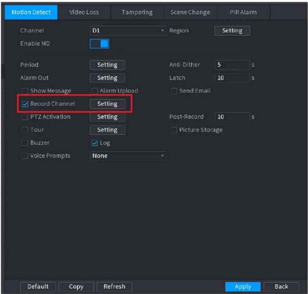
text_image
Motion Detect Video Loss Tampering Scene Change PIR Alarm Channel D1 Region Setting Enable MD Period Setting Anti-Dither 5 s Alarm Out Setting Latch 10 s Show Message Alarm Upload Send Email Record Channel Setting Post-Record 10 s PTZ Activation Setting Tour Setting Picture Storage Buzzer Log Voice Prompts None Default Copy Refresh Apply BackStep 4 Set record period. It includes edit mode and draw mode. See Figure 4-36.

If you have added a holiday, you can set the record period for the holiday.
Figure 4-36
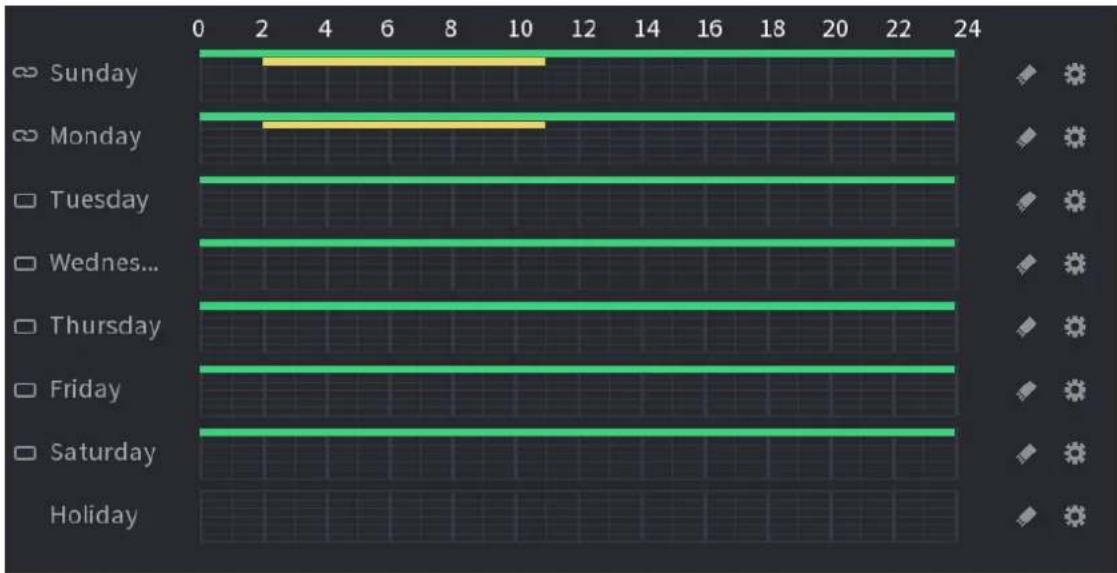
bar
| Day | Value | |---|---| | Sunday | 2 | | Monday | 10 | | Tuesday | 23 | | Wednesday... | 23 | | Thursday | 23 | | Friday | 23 | | Saturday | 23 | | Holiday | 23 |- Define the period by drawing.
1) Select a corresponding date to set.
Define for the whole week: Click ☐ next to All, all the icon switches to ☐, you can define the period for all the days simultaneously.
☐ Define for several days of a week: Click before each day one by one, the icon switches to You can define the period for the selected days simultaneously.
2) On the timeline, left click mouse and then drag to define a period.
There are six periods in one day, the Device starts recoding the selected event type in the defined period. In Figure 4-37, the different color bars stand for different record types.
◇ Green stands for general record.
◇ Yellow stands for MD (motion detection) record.
◇ Red stands for alarm record.
◇ Blue stands form intelligent record.
◇ Orange stands for MD&Alarm record.
◇ Purple stands for POS record.
Once the time period overlaps, the record priority: MD&Alarm > Alarm > POS > Intelligent > MD > General.
◇ Select a record type and then click the ◆ of the corresponding date to clear the corresponding period.
Figure 4-37
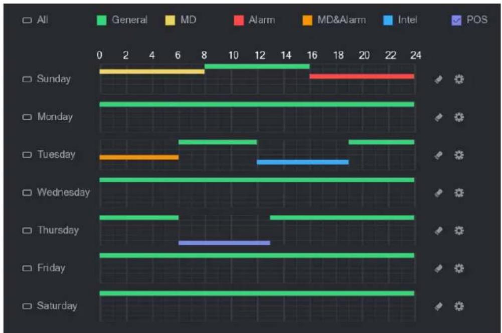
bar
| Day | All | General | MD | Alarm | MD&Alarm | Intel | POS | | --------- | --- | ------- | --- | ----- | ------- | ----- | --- | | Sunday | | 16 | 8 | 24 | | | | | Monday | | 24 | | | | | | | Tuesday | | 19 | | | | 19 | | | Wednesday | | 24 | | | | | | | Thursday | | 13 | | | | | | | Friday | | 24 | | | | | | | Saturday | | 24 | | | | | |
The MD record and alarm record function are both null if you enabled MD&Alarm function.
- Define the period by editing.
1) Select a date and then click

The Period interface is displayed. See Figure 4-38.
Figure 4-38
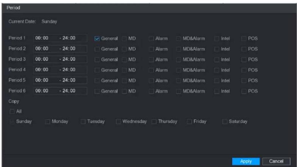
text_image
Period Current Date: Sunday Period 1 00:00 - 24:00 General MD Alarm MD&Alarm Intel POS Period 2 00:00 - 24:00 General MD Alarm MD&Alarm Intel POS Period 3 00:00 - 24:00 General MD Alarm MD&Alarm Intel POS Period 4 00:00 - 24:00 General MD Alarm MD&Alarm Intel POS Period 5 00:00 - 24:00 General MD Alarm MD&Alarm Intel POS Period 6 00:00 - 24:00 General MD Alarm MD&Alarm Intel POS Copy All Sunday Monday Tuesday Wednesday Thursday Friday Saturday Apply Cancel2) Set record type for each period.
◇ There are six periods for you to set for each day.
Under Copy, select All to apply the settings to all the days of a week, or select specific day(s) that you want to apply the settings to.
3) Click Apply to save the settings.
Step 5 Click Apply to complete the settings.

Enable auto record function so that the record plan can become activated. Refer to "4.1.4.6.3 Record control" for detailed information.
4.1.4.6.2 Snapshot Schedule
You can set schedule snapshot period.
After set schedule snapshot, device can snapshot image according to the period you set here. For example, the alarm snapshot period is from 6:00–18:00 Monday, device can snapshot during the 6:00–18:00 when an alarm occurs.
Step 1 Click Snapshot button, device goes to following interface. See Figure 4-39.

Select Main Menu > STORAGE > SCHEDULE > Snapshot, you can go to the snapshot interface.
Figure 4-39
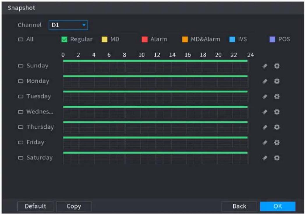
text_image
Snapshot Channel D1 All Regular MD Alarm MD&Alarm IVS POS 0 2 4 6 8 10 12 14 16 18 20 22 24 Sunday Monday Tuesday Wednesday... Thursday Friday Saturday Default Copy Back OKStep 2 Select a channel to set schedule snapshot.
Step 3 Set snapshot type as schedule. Refer to "4.2.5.2 Snapshot" for detailed information.
Step 4 Check the box to set alarm type. See Figure 4-40.
Figure 4-40

text_image
All Regular MD Alarm MD&Alarm IVS POS- When the record type is MD (motion detect), alarm, MD&Alarm, IVS and POS, enable the channel record function when corresponding alarm occurs. For example, when the alarm
type is MD, select Main Menu > ALARM > VIDEO DETECTION > Motion Detect, select the record channel and enable record function. See Figure 4-35.
- When the record type is MD (motion detect), alarm, MD&Alarm, IVS and POS, refer to "4.8.5 Video detect", "4.8.3 Alarm", "4.7.2.4 IVS" and "Step 3 POS" for detailed information.
Figure 4-41
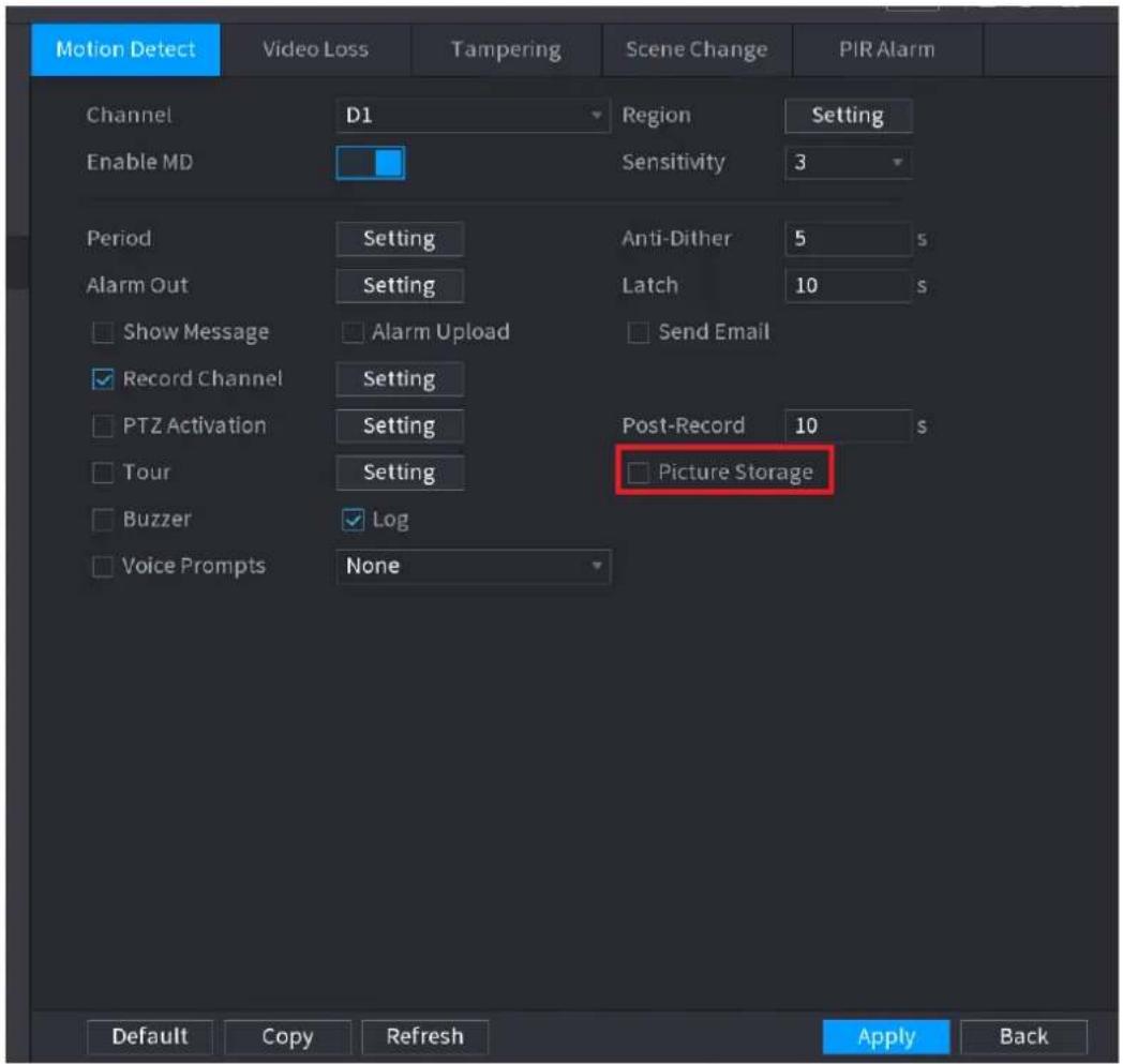
text_image
Motion Detect Video Loss Tampering Scene Change PIR Alarm Channel D1 Region Setting Enable MD Sensitivity 3 Period Setting Anti-Dither 5 s Alarm Out Setting Latch 10 s Show Message Alarm Upload Send Email Record Channel Setting Post-Record 10 s PTZ Activation Setting Tour Setting Picture Storage Buzzer Log Voice Prompts None Default Copy Refresh Apply BackStep 5 Refer to "4.1.4.6.1 Recording Schedule" to set snapshot period.
Step 6 Click Apply button to save snapshot plan.
[Non-Text]
Enable auto snapshot function so that the snapshot plan can become activated. Refer to "4.1.4.6.3 Record control" for detailed information.
4.1.4.6.3 Record Control
After set schedule record or schedule snapshot, you need to enable auto record and snapshot function so that system can automatically record or snapshot.
- Auto: System automatically records at the type and record period you set in Schedule interface.
- Manual: System records general files for all day.

You need to have storage authorities to implement the Manual record operation. Make sure the HDD has been properly installed.
Step 1 Right click mouse and then select Manual > Record or select Main Menu >
STORAGE > RECORD. See Figure 4-42.

For some series products, after you logged in, you can click the Rec button at the front panel to go to the Record interface.
Figure 4-42
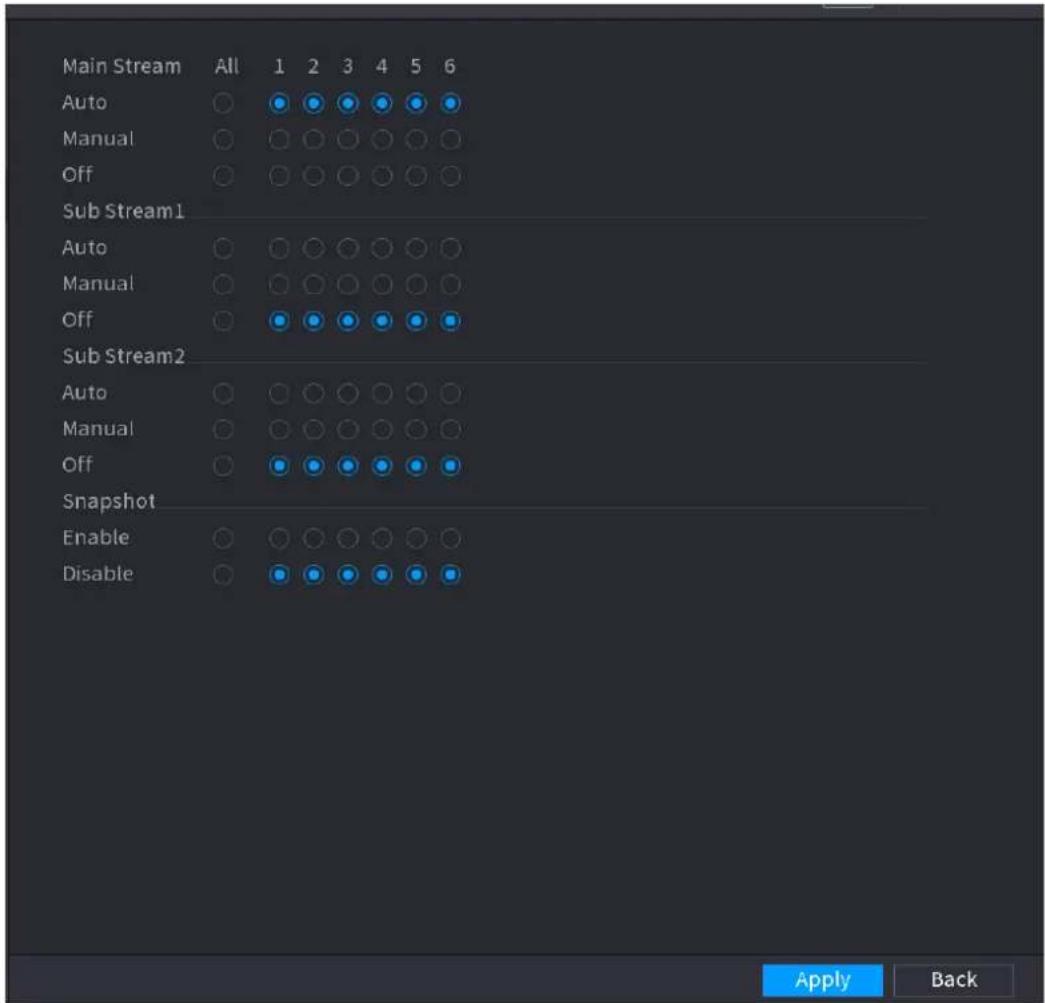
text_image
Main Stream All 1 2 3 4 5 6 Auto Manual Off Sub Stream1 Auto Manual Off Sub Stream2 Auto Manual Off Snapshot Enable Disable Apply BackStep 2 Configure parameters.
| Parameter | Description |
| Channel | Displays all the analog channels and the connected digital channels. You can select a single channel or select All. |
| Record status | • Auto: Automatically record according to the record type and recording time as configured in the recording schedule.• Manual: Keep general recording for 24 hours for the selected channel.• Off: Do not record. |
| Snapshot status | Enable or disable the scheduled snapshot for the corresponding channels. |
Step 3 Click Apply.
4.2 Camera
4.2.1 Connection
Select Main menu > REGISTRATION > Camera Registration, you can register the remote device. See Figure 4-43.
After register the remote device to the NVR, you can view the video on the NVR, and manage and storage the video file. Different series products support different remote device amount.
Figure 4-43
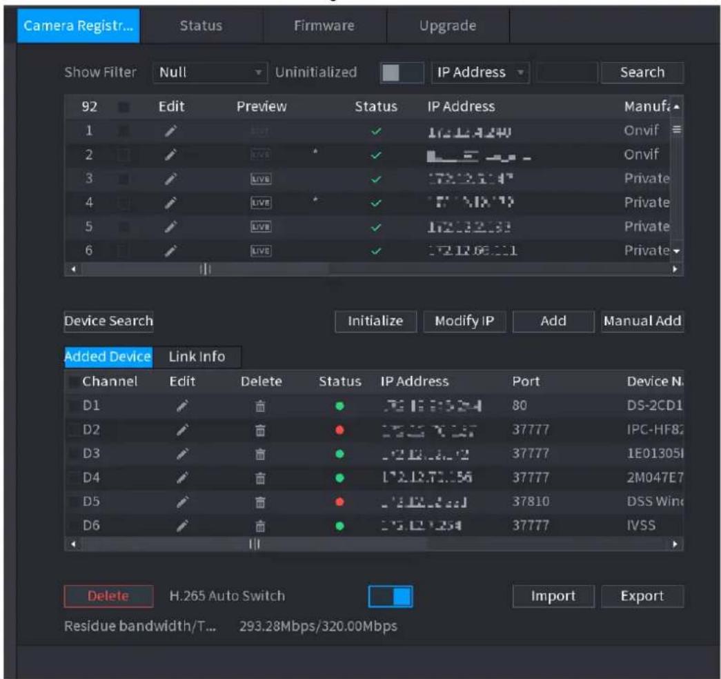
text_image
Camera Registr... Status Firmware Upgrade Show Filter Null Uninitialized IP Address Search 92 Edit Preview Status IP Address Manufa 1 Onvif 2 Onvif 3 Private 4 Private 5 Private 6 Private Device Search Initialize Modify IP Add Manual Add Added Device Link Info Channel Edit Delete Status IP Address Port Device N. D1 80 DS-2CD1 D2 37777 IPC-HF82 D3 37777 1E013051 D4 37777 2M047E7 D5 37810 DSS Wine D6 37777 IVSS Delete H.265 Auto Switch Import Export Residue bandwidth/T... 293.28Mbps/320.00Mbps4.2.1.1 Changing IP address
Step 1 Select Main Menu > REGISTRATION > Camera Registration, check the box before
the camera name and then click Modify IP or click the before the camera name.
Enter Modify IP interface. See Figure 4-44.

Check the box before several cameras, change the IP addresses of several cameras at the same time.
Figure 4-44
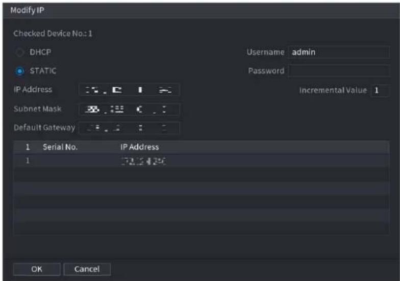
text_image
Modify IP Checked Device No.:1 DHCP STATIC IP Address Subnet Mask Default Gateway Username admin Password Incremental Value 1 1 Serial No. IP Address 1 32.5420 OK CancelStep 2 Select IP mode.
- Check DHCP, there is no need to input IP address, subnet mask, and default gateway. Device automatically allocates the IP address to the camera.
- Check Static, and then input IP address, subnet mask, default gateway and incremental value.

- If it is to change several devices IP addresses at the same time, input incremental value. Device can add the fourth address of the IP address one by one to automatically allocate the IP addresses.
- If there is IP conflict when changing static IP address, device pops up IP conflict dialogue box. If batch change IP address, device automatically skips the conflicted IP and begin the allocation according to the incremental value
Step 3 Input remote device user name and password.

When change IP addresses of several devices at the same time, make sure the cameras user name and passwords are the same.
Step 4 Click OK button to save settings.
After the modification and then search again, device displays new IP address.
Auto Changing H.265
For the remote device that first registered to the system, it can automatically adopts encode format as H.265 if you enable H.265 Auto switch function.
Click H.265 Auto Switch button at the bottom of the interface, it is from

The function is enabled. See Figure 4-45.
Figure 4-45
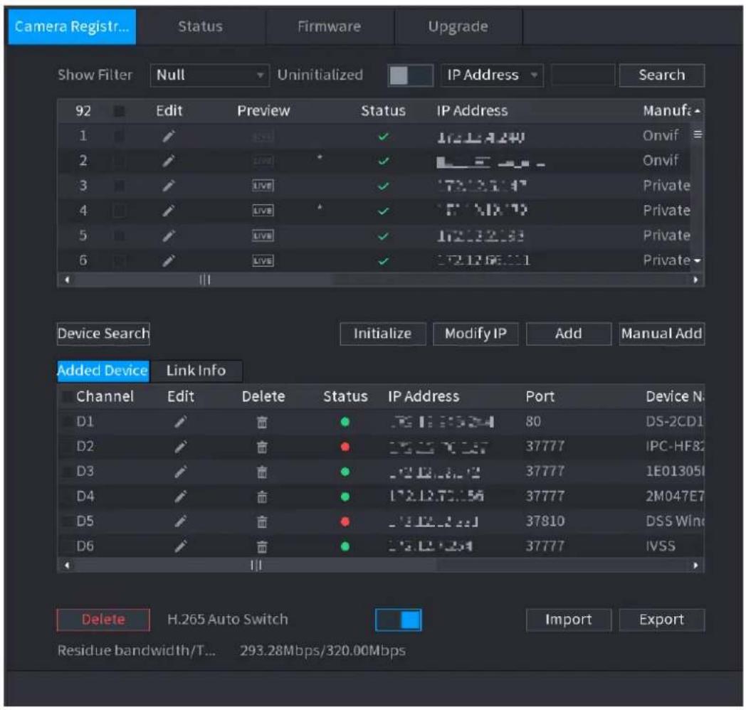
text_image
Camera Registr... Status Firmware Upgrade Show Filter Null Uninitialized IP Address Search 92 Edit Preview Status IP Address Manufa 1 ✓ ✓ ✓ Onvif 2 ✓ ✓ ✓ Onvif 3 ✓ ✓ ✓ Private 4 ✓ ✓ ✓ Private 5 ✓ ✓ ✓ Private 6 ✓ ✓ ✓ Private Device Search Initialize Modify IP Add Manual Add Added Device Link Info Channel Edit Delete Status IP Address Port Device N. D1 ✓ ✓ ● 80 DS-2CD1 D2 ✓ ✓ ● 37777 IPC-HF82 D3 ✓ ✓ ● 37777 1E01305I D4 ✓ ✓ ● 37777 2M047E7 D5 ✓ ✓ ● 37810 DSS Wine D6 ✓ ✓ ● 37777 IVSS Delete H.265 Auto Switch Import Export Residue bandwidth/T... 293.28Mbps/320.00Mbps4.2.1.2 IP Export
Device can export the Added device list to your local USB device.
Step 1 Insert the USB device and then click the Export button. The Browse interface is displayed. See Figure 4-46.
Figure 4-46
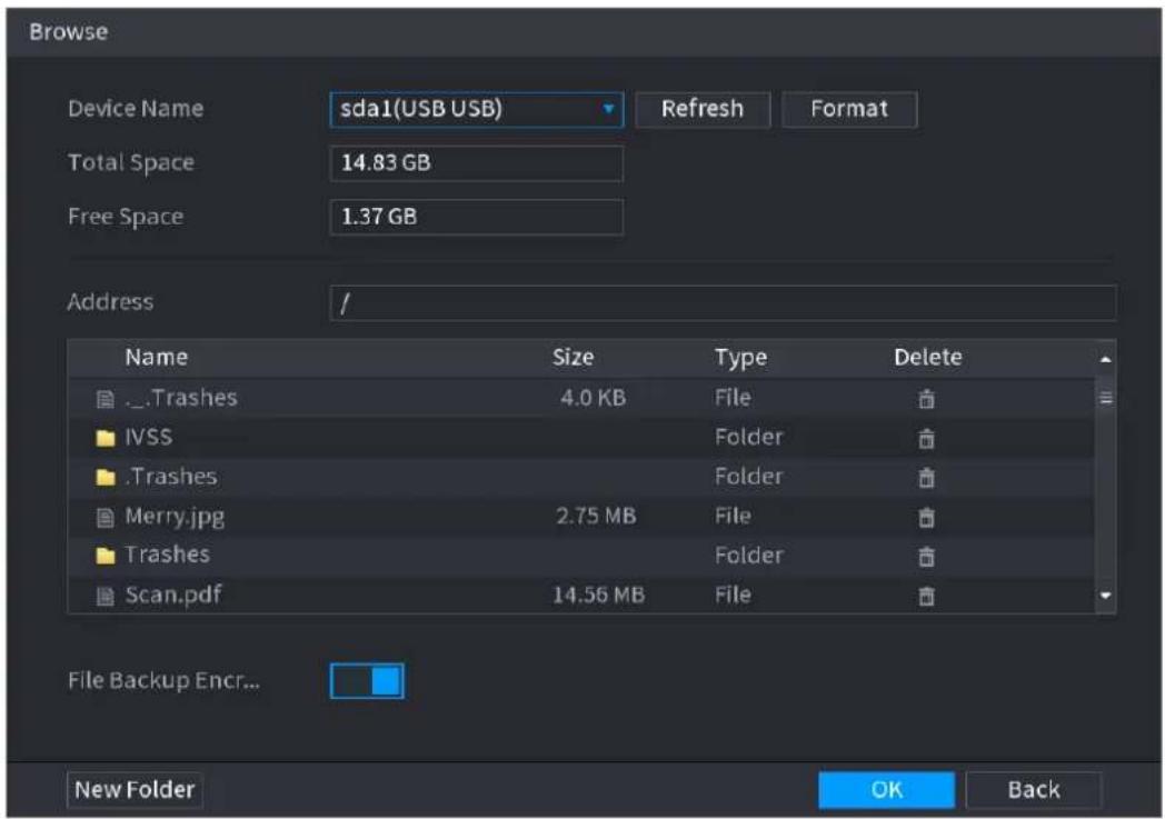
text_image
Browse Device Name sda1(USB USB) Refresh Format Total Space 14.83 GB Free Space 1.37 GB Address / Name Size Type Delete ...Trashes 4.0 KB File IVSS Folder ...Trashes Folder Merry.jpg 2.75 MB File Trashes Folder Scan.pdf 14.56 MB File File Backup Encr... New Folder OK BackStep 2 Select Address to save export file.
Step 3 Click the OK button.
Device pops up a dialogue box to remind you successfully exported.

When exporting IP address, the File Backup Encryption check box is checked by default. The file information includes IP address, port, channel number, manufacturer, user name, and password.
- If you select the File Backup Encryption check box, the file format is .backup.
- If you clear the File Backup Encryption check box, the file format is .csv. In this case, there might be a risk of data leakage.
4.2.1.3 IP Import
Step 1 Click Import button.
The Browse interface is displayed. See Figure 4-47.
Figure 4-47
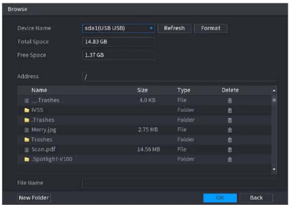
text_image
Browse Device Name sda1(USB USB) Refresh Format Total Space 14.83 GB Free Space 1.37 GB Address / Name Size Type Delete ...Trashes 4.0 KB File IVSS Folder .Trashes Folder Merry.jpg 2.75 MB File Trashes Folder Scan.pdf 14.56 MB File .Spotlight-V100 Folder File Name New Folder OK BackStep 2 Go to Address to select the import file and then click the OK button.
System pops up a dialogue box to remind you successfully imported.

If the imported IP has conflicted with current added device, system pops up a dialogue box to remind you. You have two options.
Step 3 Click OK button.
The imported information is on the Added Device list.
4.2.2 Remote Device Initialization
Remote device initialization can change remote device login password and IP address.

- When connect a camera to the NVR via PoE port, NVR automatically initialize the camera. The camera adopts NVR current password and email information by default.
- When connect a camera to the NVR via PoE port after NVR upgraded to the new version, the NVR may fail to initialize the camera. Go to the Registration interface to initialize the camera.
Step 1 Select Main Menu > CAMERA > Camera Registration.
The Camera Registration interface is displayed.
Step 2 Click Device Search and then click Uninitialized.
Device displays camera(s) to be initialized.
Step 3 Select a camera to be initialized and then click Initialize.
The Enter Password interface is displayed. See Figure 4-48.
Figure 4-48
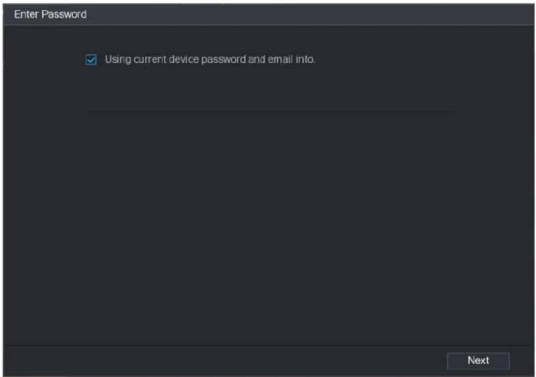
text_image
Enter Password ✓ Using current device password and email info. NextStep 4 Set remote device password and email information.

If you want to use current device password and email information, the remote device automatically uses NVR admin account information (login password and email). There is no need to set password and email. Go to step 6.
1) Cancel Using current device password and email info, The Enter Password interface is displayed. See Figure 4-49.
Figure 4-49
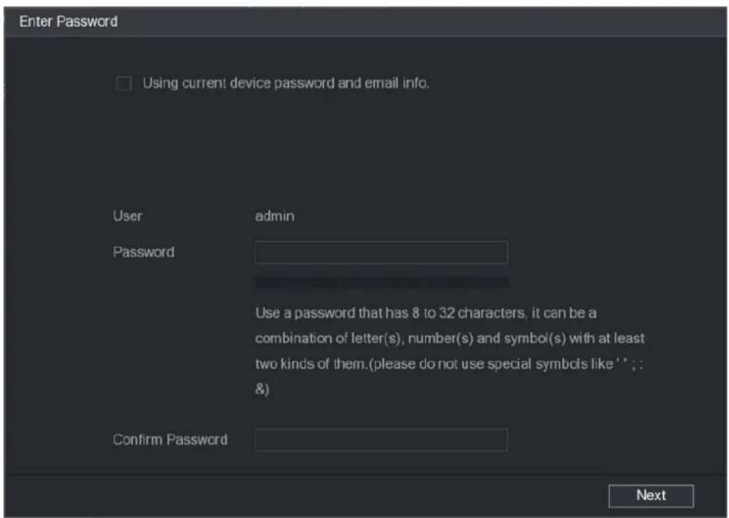
text_image
Enter Password □ Using current device password and email info. User admin Password Use a password that has 8 to 32 characters, it can be a combination of letter(s), number(s) and symbol(s) with at least two kinds of them.(please do not use special symbols like ' '; &) Confirm Password Next2) Configure parameters. See Table 4-10.
Table 4-10
| Parameter | Description |
| User | The default is admin. |
| Password | The new password can be set from 8 characters through 32 characters and contains at least two types from number, letter and special characters (excluding "", "", ";", :, ": " &").Enter a strong password according to the password strength bar indication. |
| Confirm Password |

For your device own safety, create a strong password of your own choosing. We also recommend you change your password periodically especially in the high security system.
Step 5 Click Next button.
The Password Protection interface is displayed. See Figure 4-50.
Figure 4-50

text_image
Password Protection ✓ Email Address To reset password, please input properly or update in time Back Next SkipStep 6 Set email information.
Input an email address for reset password purpose.

Cancel the box and then click Next or Skip if you do not want to input email information here.
Step 7 Click Next button.
The Network interface is displayed. See Figure 4-51.
Figure 4-51
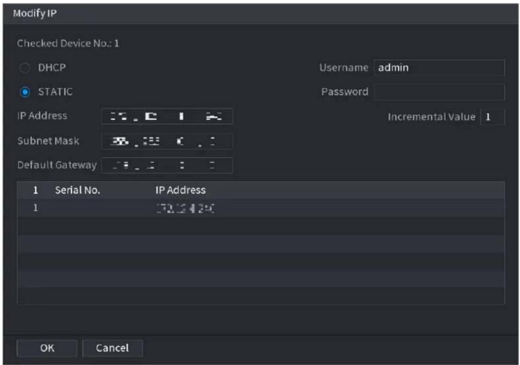
text_image
Modify IP Checked Device No.: 1 DHCP STATIC Username admin Password IP Address Incremental Value 1 Subnet Mask Default Gateway Serial No. IP Address 1 32.2434 OK CancelStep 8 Set camera IP address.
- Check DHCP, there is no need to input IP address, subnet mask, and default gateway. Device automatically allocates the IP address to the camera.
- Check Static, and then input IP address, subnet mask, default gateway and incremental value.

- If it is to change several devices IP addresses at the same time, input incremental value. Device can add the fourth address of the IP address one by one to automatically allocate the IP addresses.
- If there is IP conflict when changing static IP address, device pops up IP conflict dialogue box. If batch change IP address, device automatically skips the conflicted IP and begin the allocation according to the incremental value
Step 9 Click Next button.
The Device Initialization interface is displayed. See Figure 4-52.
Figure 4-52
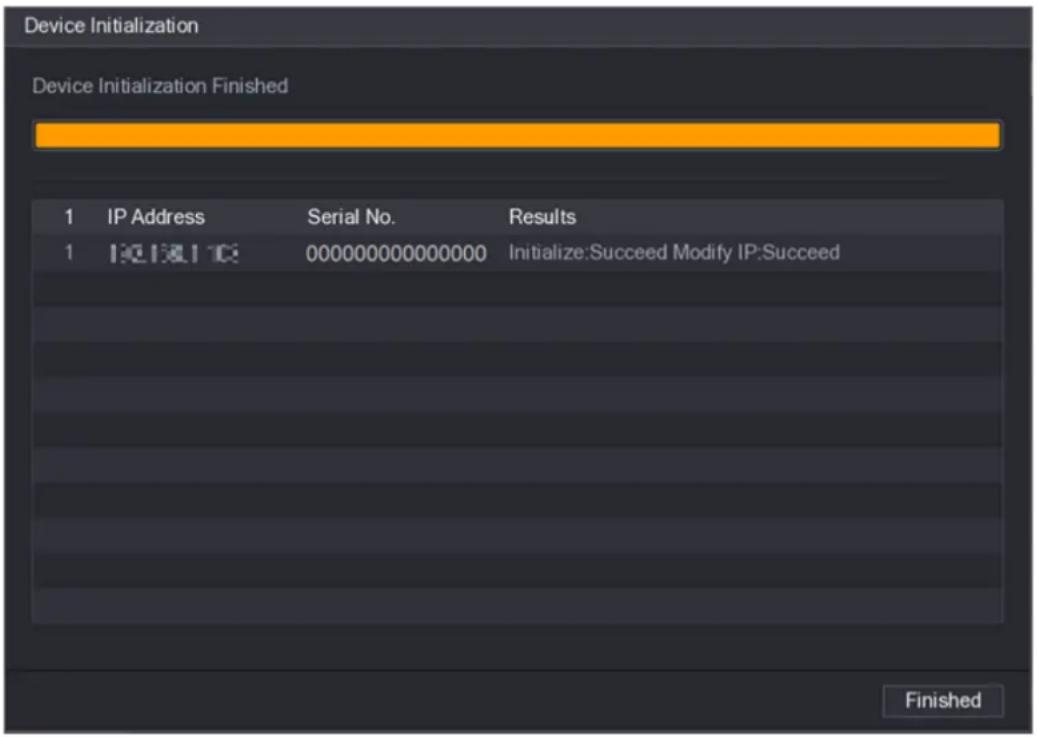
text_image
Device Initialization Device Initialization Finished 1 IP Address Serial No. Results 1 000000000000000 Initialize:Succeed Modify IP:Succeed FinishedStep 10 Click Finished to complete the setup.
4.2.3 Short-Cut Menu to Register Camera
If you have not registered a remote device to a channel, go to the preview interface to add.
Step 1 On the Preview interface, Move your mouse to window.
There is an icon "+ " on the channel window. See Figure 4-53.
Figure 4-53
natural_image
Dark background with a small circular gray icon containing a white star-like symbol (no text or symbols)Step 2 Click "+" device pops up interface to add network camera. Refer to "4.1.4.4 Registration" for detailed information.
4.2.4 Image
You can set network camera parameters according to different environments. It is to get the best video effect.
Step 1 Select Main Menu> CAMERA> IMAGE.
The IMAGE interface is displayed. See Figure 4-54.
Figure 4-54
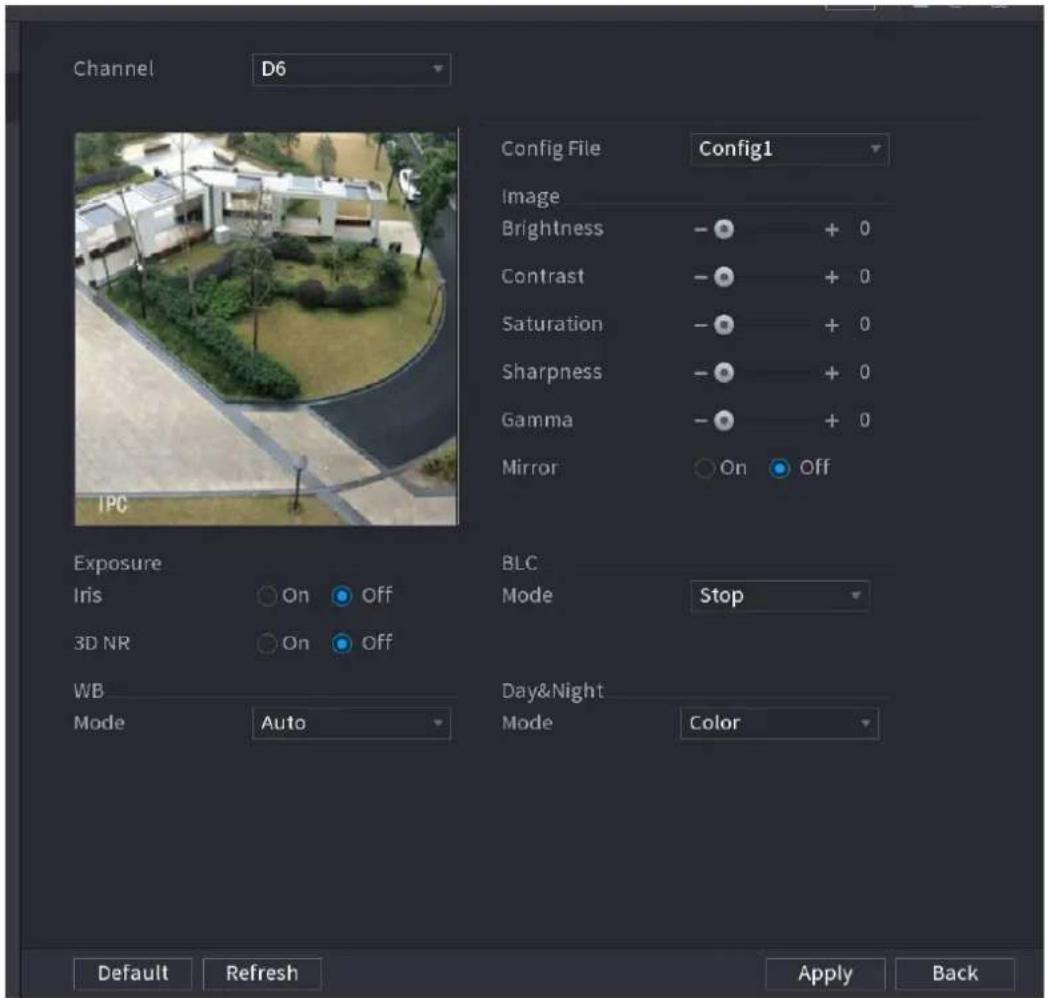
text_image
Channel D6 Config File Config1 Image Brightness - + 0 Contrast - + 0 Saturation - + 0 Sharpness - + 0 Gamma - + 0 Mirror On Off IPC Exposure Iris On Off 3D NR On Off WB Mode Auto BLC Mode Stop Day&Night Mode Color Default Refresh Apply BackStep 2 Configure parameters. See Table 4-11.

Different series network camera displays different parameters. The actual product shall prevail.
Step 3 Click Apply.
Table 4-11
| Parameter | Description | |
| Channel | In the Channel list, select the channel that you want to configure. | |
| Config File | There are three config files for you. System has configured the corresponding parameters for each file, you can select according to your actual situation. | |
| Brightness | Adjusts the image brightness. The bigger the value is, the brighter the image will become. Adjusts the brightness according to actual environment. | |
| Parameter | Description | |
| Contrast | Adjusts the image contrast. The bigger the value is, the more obvious the contrast between the light area and dark area will become. Adjusts the contrast according to actual environment. | |
| Saturation | Adjusts the color shades. The bigger the value, the lighter the color will become. Adjusts the saturation according to actual environment. | |
| Sharpness | Adjusts the sharpness of image edge. The bigger the value is, the more obvious the image edge is. Adjusts the sharpness according to actual environment. | |
| Gamma | It is to adjust image brightness and enhance the image dynamic display range. The bigger the value is, the more bright the video is. | |
| Mirror | Enable the function, the left and right side of the video image will be switched. It is disabled by default.This function is for some series products only. | |
| Field of view | It is to set monitor video display direction. It includes normal, reflection, lobby 1, lobby 2. | |
| Exposure | • Auto iris | • It is for the camera of auto iris only.• After enable auto iris function, the iris can automatically zoom in/zoom out according to the brightness of the environment and the image brightness changes too.• If disable the auto iris function, the iris does not automatically zoom in/zoom out according to the brightness of the environment when the iris is at the biggest value. |
| • 3D NR | • This function specially applies to the image which frame rate is configured as 2 at least. It reduces the noises by making use of the information between two frames. The bigger the value is, the better the effect. | |
| Parameter | Description | |
| BLC | You can set camera BLC mode.Self-adaptive: In the backlight environment, the system can automatically adjust image brightness to clearly display the object.BLC:Default: The device auto exposures according to the environments situation so that the darkest area of the video is clearedCustomize: After select the specified zone, the system can expose the specific zone so that the zone can reach the proper brightness.WDR: In backlight environment, it can lower the high bright section and enhance the brightness of the low bright section. So that you can view these two sections clearly at the same time.HLC: In the backlight environment, it can lower the brightness of the brightest section and reduce the area of the halo and lower the brightness of the whole video.Stop: It is to disable the BLC function. | |
| WB | You can set camera WB mode. It can affect the image whole hue so that the image can accurately displays the environment status.Different cameras supports different WB modes such as auto, manual ,natural light, outdoor and etc. | |
| Day & Night | Configure the color and black&white mode of the image. This setting is not affected by the configuration files. The default setting isAuto.Color: The camera outputs color image only.Auto: Depends on the camera, such as overall brightness and whether there is an IR light, either color image or black&white image is output.B/W: The camera outputs Black and white image only.Sensor: It is to set when there is peripheral connected IR light.The Sensor item is for some non-IR device only. | |
4.2.5 Encode
You can set video bit stream and image parameters.
4.2.5.1 Encode
You can set video bit stream parameters such as bit stream type, compression, resolution.

Some series products support three streams: main stream, sub stream 1, sub stream 2. The sub stream maximally supports 1080P.
Step 1 Select Main menu > CAMERA > ENCODE > ENCODE.
The ENCODE interface is displayed. See Figure 4-55.
Figure 4-55
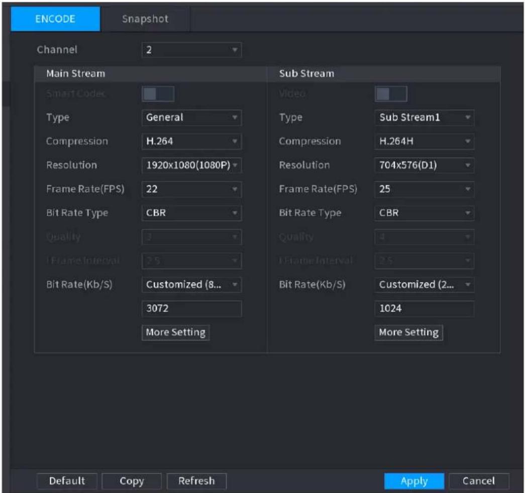
text_image
ENCODE Snapshot Channel 2 Main Stream Smart Codec Type General Compression H.264 Resolution 1920x1080(1080P) Frame Rate(FPS) 22 Bit Rate Type CBR Quality 3 Frame Interval 7 S Bit Rate(Kb/S) Customized (8... 3072 More Setting Sub Stream Video Type Sub Stream1 Compression H.264H Resolution 704x576(D1) Frame Rate(FPS) 25 Bit Rate Type CBR Quality 4 Frame Interval 2 S Bit Rate(Kb/S) Customized (2... 1024 More Setting Default Copy Refresh Apply CancelStep 2 Configure parameters. See Table 4-12.
Step 3 Click More Setting.
The More Setting interface is displayed. See Figure 4-56.
Table 4-12
| Parameter | Description |
| Channel | In the Channel list, select the channel that you want to configure the settings for. |
| Smart Codec | Enable the smart codec function. This function can reduce the video bit stream for non-important recorded video to maximize the storage space.● :  I.● : I.● :  J. J. |
| Type | Main Stream: In the Type list, select General, MD (Motion Detect), or Alarm.Sub Stream: This setting is not configurable. |
| Compression | In the Compression list, select the encode mode.H.265: Main profile encoding. This setting is recommended.H.264H: High profile encoding. Low bit stream with high definition.H.264: Main profile encoding.H.264B: Baseline profile encoding. This setting requires higher bit stream compared with other settings for the same definition. |
| Resolution | In the Resolution list, select resolution for the video.The maximum video resolution might be different dependent on your device model. |
| Frame Rate (FPS) | Configure the frames per second for the video. The higher the value is, the clearer and smoother the image will become. Frame rate changes along with the resolution.Generally, in PAL format, you can select the value from 1 through 25; in NTSC format, you can select the value from 1 through 30. However, the actual range of frame rate that you can select depends on the capability of the Device. |
| Bit Rate Type | In the Bit Rate Type list, select CBR (Constant Bit Rate) or VBR (Variable Bit Rate). If you select CBR, the image quality cannot be configured; if you select VBR, the image quality can be configured. |
| Quality | This function is available if you select VBR in the Bit Rate List.The bigger the value is, the better the image will become. |
| I Frame Interval | The interval between two reference frames. |
| Bit Rate (Kb/S) | In the Bit Rate list, select a value or enter a customized value to change the image quality. The bigger the value is, the better the image will become. |
Figure 4-56
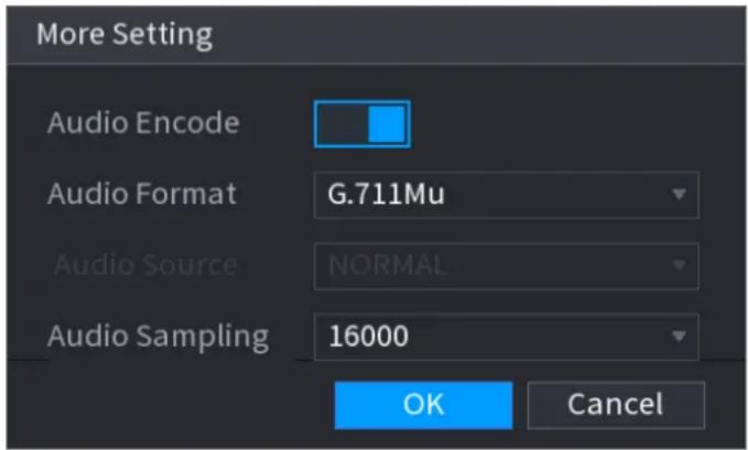
text_image
More Setting Audio Encode Audio Format G.711Mu Audio Source NORMAL Audio Sampling 16000 OK CancelStep 4 Configure parameters. See Table 4-13.
Table 4-13
| Parameter | Description |
| Audio Encode | This function is enabled by default for main stream. You need to manually enable it for sub stream 1. Once this function is enabled, the recorded video file is composite audio and video stream. |
| Audio Format | In the Audio Format list, select a format: G711a, G711u, PCM, AAC. |
| Audio Sampling | • In the Audio Sampling list, you can select audio sampling rate. |
Step 5 Click OK.
Back to Encode interface.
Step 6 Click Apply.
4.2.5.2 Snapshot
You can set snapshot mode, image size, quality and interval.
Step 1 Select Main menu > CAMERA > ENCODE > Snapshot.
The SNAPSHOT interface is displayed. See Figure 4-57.
Figure 4-57

text_image
ENCODE Snapshot Snapshot 1 /Time Channel D1 Mode Timing Image Size 1200x720(720P) Image Quality 5 Interval 1 Second Refresh Apply CancelStep 2 Configure parameters. See Table 4-14.
Step 3 Click Apply.
Table 4-14
| Parameter | Description |
| Manual Snap | In theManual Snaplist, select how many snapshots you want to take each time. |
| Channel | In theChannellist, select the channel that you want to configure the settings for. |
| Mode | In theModelist, you can selectTiming, orTrigger.Timing: The snapshot is taken during the scheduled period.Trigger: The snapshot is taken when there is an alarm event occurs, such as motion detection event, video loss, and loca alarms. |
| Image Size | In the Image Size list, select a value for the image. The bigger the value is, the better the image will become. |
| Image Quality | Configure the image quality by 6 levels. The higher the level is, the better the image will become. |
| Interval | Configure or customize the snapshot frequency. Max. supports 3600 seconds/image. |
4.2.6 Channel Name
You can set customized channel name.
Step 1 Select Main Menu > CAMERA > CAM NAME.
The CAM NAME interface is displayed. See Figure 4-58.
Figure 4-58
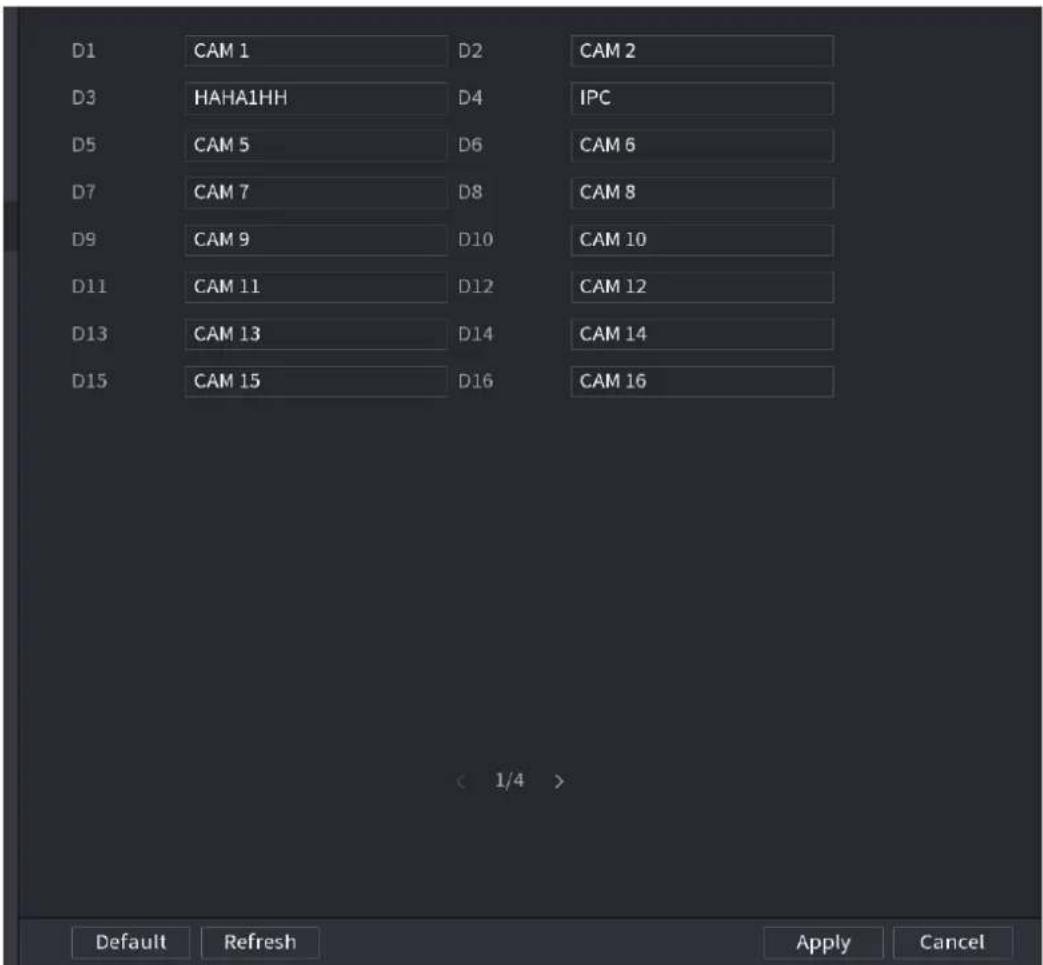
text_image
D1 CAM 1 D2 CAM 2 D3 HAHA1HH D4 IPC D5 CAM 5 D6 CAM 6 D7 CAM 7 D8 CAM 8 D9 CAM 9 D10 CAM 10 D11 CAM 11 D12 CAM 12 D13 CAM 13 D14 CAM 14 D15 CAM 15 D16 CAM 16 < 1/4 > Default Refresh Apply CancelStep 2 Modify a channel name.

- You can only change the camera connected via the private protocol.
● The channel name supports 63 English characters.
Step 3 Click Apply.
4.2.7 Remote Upgrade
You can upgrade the connected network camera firmware. It includes online upgrade and file upgrade.
Step 1 Select Main Menu > CAMERA > REGISTRATION > Upgrade.
The Upgrade interface is displayed. See Figure 4-59.
Figure 4-59
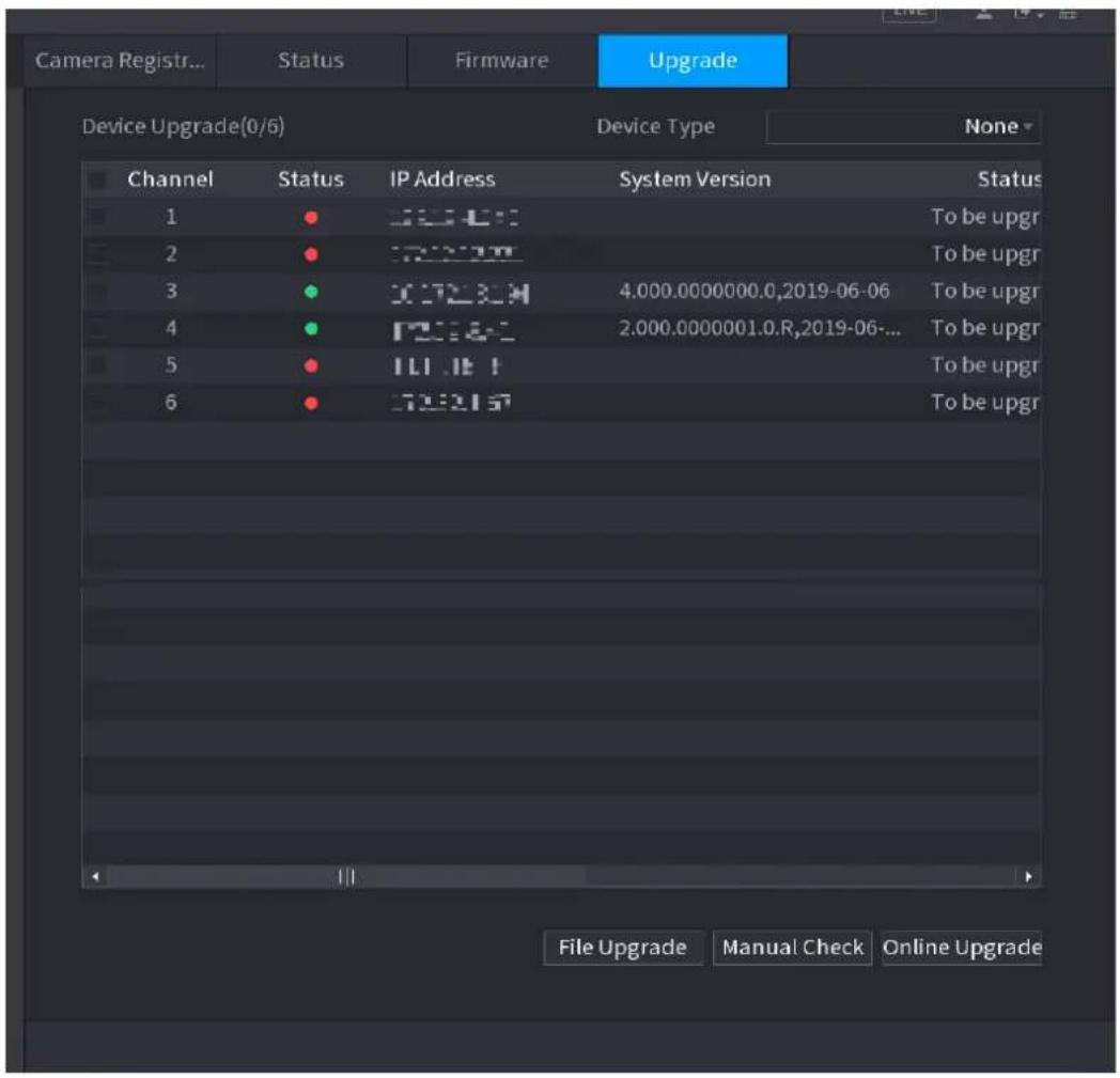
text_image
Camera Registr... Status Firmware Upgrade Device Upgrade(0/6) Device Type None Channel Status IP Address System Version Status 1 ● 4.000.000000 To be upgr 2 ● 4.000.000000 To be upgr 3 ● 4.000.000000.0,2019-06-06 To be upgr 4 ● 4.000.000000.0.R,2019-06-... 5 ● 4.000.000000.0. 6 ● 4.000.000000. File Upgrade Manual Check Online UpgradeStep 2 Update the firmware of the connected remote device.
- Online Upgrade
1) Select a remote device and then click the Detect button on the right side, or check a box to select a remote device and then click Manual Check. System detects the new version on the cloud.
2) Select a remote device that has new version and then click online upgrade. After successful operation, system pops up upgrade successful dialogue box.
- File upgrade
1) Select a channel and then click File Upgrade.
2) Select upgrade file on the pop-up interface.
3) Select the upgrade file and then click OK button.
After successful operation, system pops up upgrade successful dialogue box.

If there are too much remote devices, select Device Type from the drop-down list to search the remote device you desire.
4.2.8 Remote Device Info
4.2.8.1 Device Status
You can view the connection and alarm status of the corresponding channel.
Select Main Menu > CAMERA > REGISTRATION > Status, the Status interface is displayed.
See Figure 4-60. Refer to Table 4-15 for detailed information.
Figure 4-60
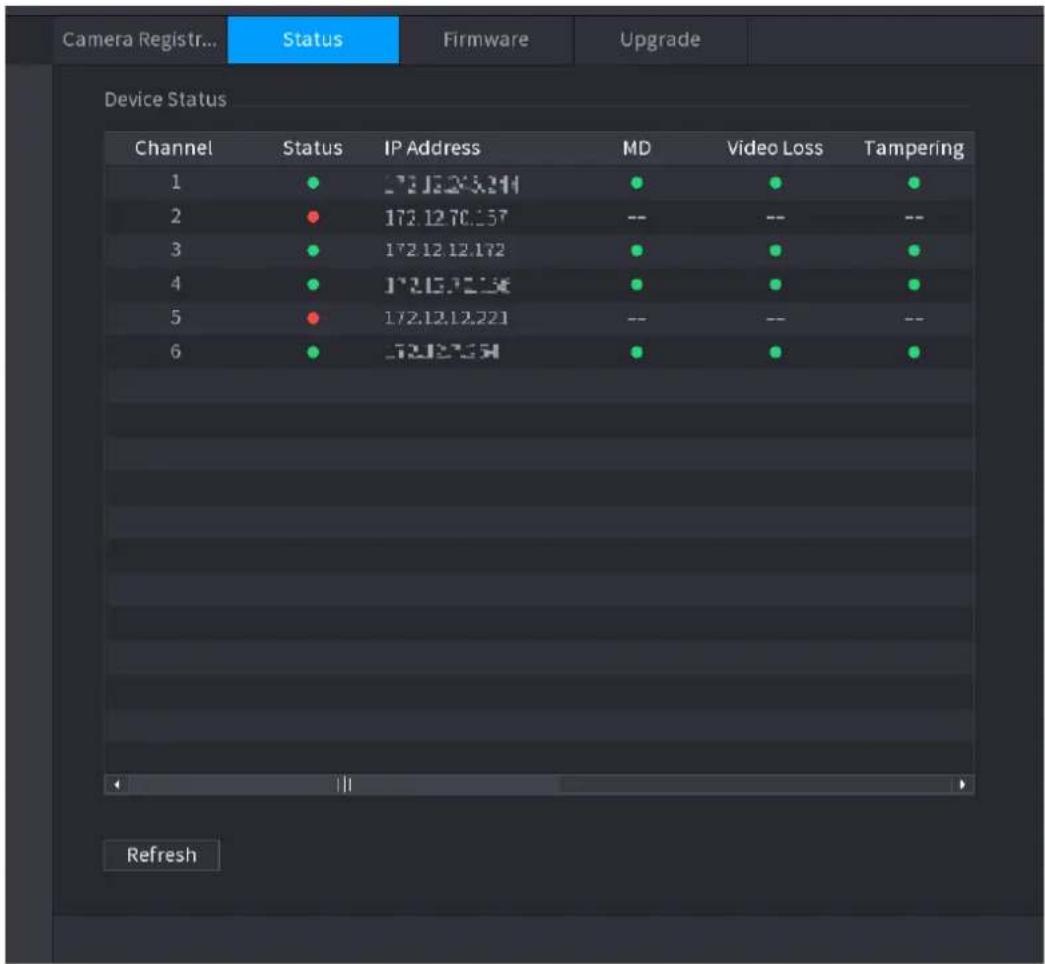
text_image
Camera Registr... Status Firmware Upgrade Device Status Channel Status IP Address MD Video Loss Tampering 1 ● 172.12.20.244 ● ● ● 2 ● 172.12.70.357 -- -- -- 3 ● 172.12.12.172 ● ● ● 4 ● 172.15.70.236 ● ● ● 5 ● 172.12.12.221 -- -- -- 6 ● 172.27.58 ● ● ● RefreshTable 4-15
| Icon | Description | Icon | Description |
| IPC works properly. | IPC does not support. | ||
| There is an alarm. | Video loss occurs. |
4.2.8.2 Firmware
You can view IP address, manufacturer, type, system version of the connected remote device.
Select Main Menu > CAMERA > REGISTRATION > Firmware, the Firmware interface is displayed. See Figure 4-61.
Figure 4-61
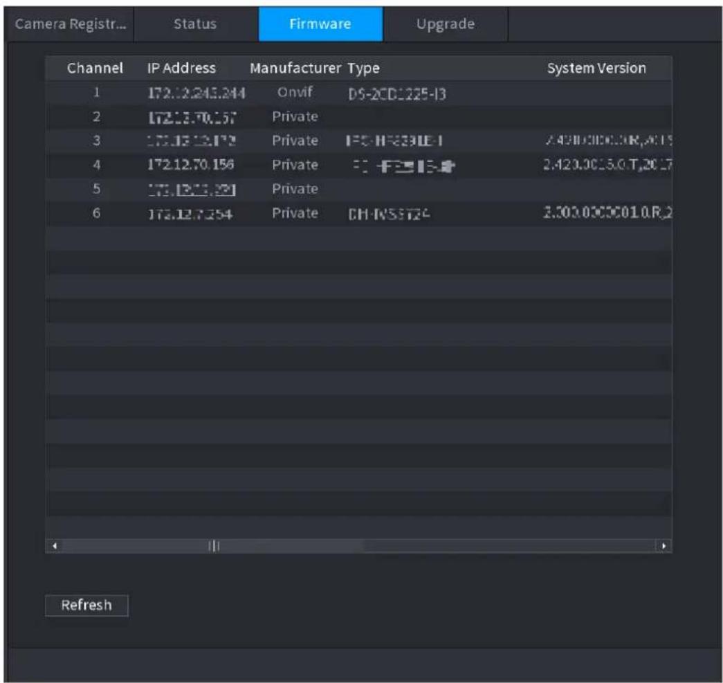
text_image
Camera Registr... Status Firmware Upgrade Channel IP Address Manufacturer Type System Version 1 172.12.245.244 Onvif DS-2CD-1225-13 2 172.12.70.157 Private 3 172.12.12.172 Private F5-F5-231E-1 2.420.000000R,ACI 5 4 172.12.70.156 Private F5-F5-231E-1 2.420.000000T,ACI 7 5 172.12.12.171 Private 6 172.12.7354 Private CH-RSSTZ4 2.300.00000010.R,2 Refresh4.3 Live View
After you logged in, the system goes to multiple-channel live view mode by default. You can view the monitor video of each channel.
The displayed window amount may vary. The actual product shall prevail.
4.3.1 Preview
On Preview interface, you can view the monitor video of each channel. The corresponding channel displays date, time, and channel name after you overlay the corresponding information. Refer to the following table for detailed information. See Table 4-16.
Table 4-16
| SN | Icon | Description |
| 1 |  | When current channel is recording, system displays this icon. |
| 2 |  | When motion detection alarm occurs, system displays this icon. |
| 3 |  | When video loss alarm occurs, system displays this icon. |
| 4 |  | When current channel is in monitor lock status, system displays this icon. |
| 5 |  | When the device connects to the network camera remotely, system displays this icon.This function is for some series products only. |
4.3.2 Navigation bar
You can quickly perform operation through the icon on the navigation bar.

- Different series products may display different navigation bar icons. Refer to the actual product for detailed information.
- Select Main Menu > SYSTEM > GENERAL > General to enable navigation bar function and then click Apply; otherwise you cannot see the following interface.
Step 1 On the preview interface, left click mouse,
You can see navigation bar. See Figure 4-62. Refer to Table 4-17 to view detailed information.
Figure 4-62

text_image
1 2 3 4 5 6 7 8 9 10 11 12 13 14Table 4-17
| Icon | Function | |
 | Open Main Menu. | |
 | Expand or condense the navigation bar. | |
 | Select view layout. | |
 | Go to the previous screen. | |
| Icon | Function | |
 | Go to the next screen. | |
 | Enable tour function. The icon switches to  Close the tour or the triggered tour operation has cancelled, device restores the previous preview video. Close the tour or the triggered tour operation has cancelled, device restores the previous preview video. | |
 | Open the PTZ control panel. For details, see "4.4.2 PTZ Control". | |
 | Open the Color Setting interface. For details, see "4.4.2 PTZ Control."This function is supported only in single-channel layout. | |
 | Open the record search interface. For detail, see "4.6.2 Search Interface." | |
 | Open the Broadcast interface. For detail, see "4.17.3 Broadcast." | |
 | Open the EVENT interface to view the device alarm status. For details, see "4.8.2 Alarm Status." | |
 | Open the CHANNEL INFO interface to display the information of each channel. For details, see " 4.3.2.1 Channel Info." | |
 | Open the CAMERA REGISTRATION interface. For details, see "4.1.4.4 Registration." | |
 | Open the NETWORK interface. For details, see " 4.12 Network." | |
 | Open the HDD MANAGER interface. For details, see " 4.13.3 HDD." | |
 | Open the USB MANAGER interface. For details about USB operations, see " 4.3.2.2 USB Manager." | |
4.3.2.1 Channel Info
After the remote device registered to the corresponding channel, you can view its status such as alarm status, record status, connection status, record mode, etc.
- Alarm status: It includes motion detection alarm, video loss alarm, tampering alarm.
- Record status: System is recording or not.
● Bit Rate: System displays bit rate information.
● Status: current channel connection status.

Click button, system goes to the channel information setup interface. You can view information of the corresponding channel. See Figure 4-63.
Figure 4-63
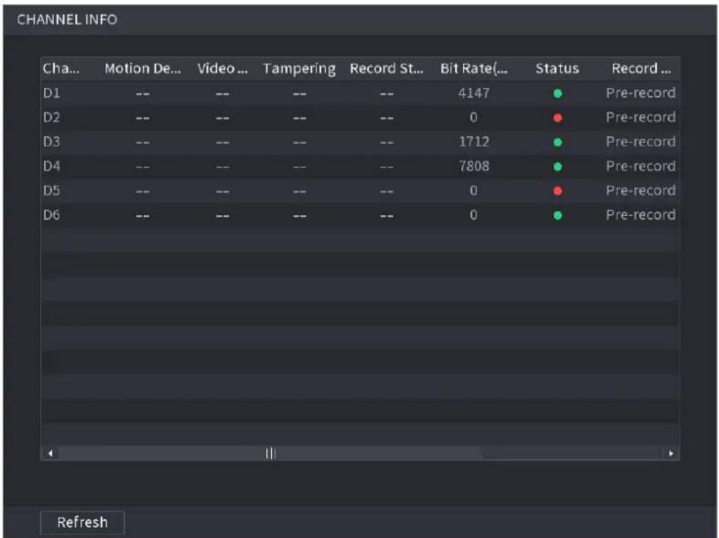
text_image
CHANNEL INFO Cha... Motion De... Video ... Tampering Record St... Bit Rate(... Status Record ... D1 -- -- -- -- 4147 Pre-record D2 -- -- -- -- 0 Pre-record D3 -- -- -- -- 1712 Pre-record D4 -- -- -- -- 7808 Pre-record D5 -- -- -- -- 0 Pre-record D6 -- -- -- -- 0 Pre-record Refresh4.3.2.2 USB Manager
After connecting the USB device, you can copy log, config file to USB device or update NVR system.
Click a system goes to HDD Manager interface. You can view and manage HDD information. See Figure 4-64.
Here you can view USB information, backup file, and update system. Refer to "4.11 File Backup", "4.10.1 Log", "4.10.4.2 IMP/EXP", "4.10.4.4 System Update" for detailed information.
Figure 4-64
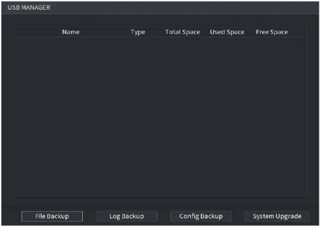
text_image
USB MANAGER Name Type Total Space Used Space Free Space File BackupLoad Backup Config Backup System Upgrade4.3.3 Preview Control Interface
Move your mouse to the top center of the video of current channel; you can see system pops up the preview control interface. See Figure 4-65. If your mouse stays in this area for more than 6 seconds and has no operation, the control bar automatically hides.

Slight difference may be found on the user interface.
Figure 4-65
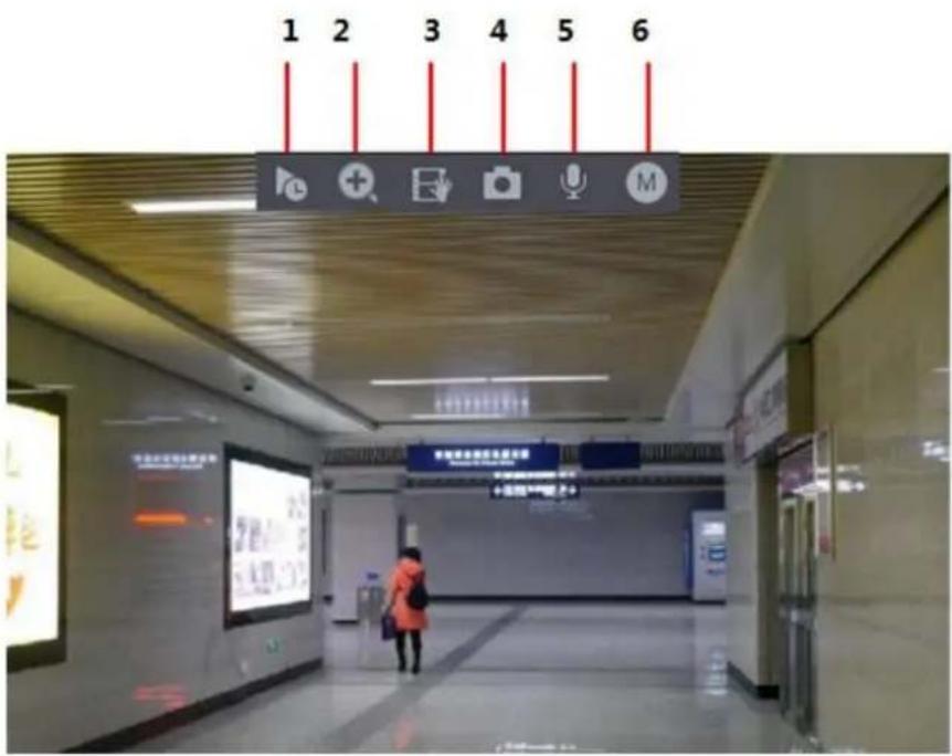
text_image
1 2 3 4 5 64.3.3.1 Instant Replay
You can playback the previous 5-60 minutes record of current channel.
Click to go to the instant replay interface. See Figure 4-66.
Figure 4-66
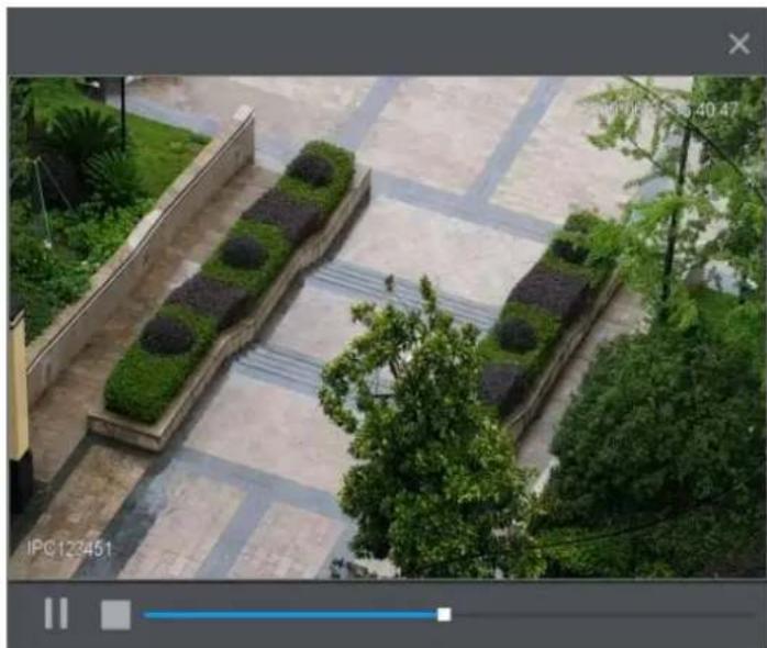
natural_image
Aerial view of a paved plaza with trimmed hedges and trees, no visible text or symbols.Instant replay is to playback the previous 5 minutes to 60 minutes record of current channel.
- Move the slider to choose the time you want to start playing.
● Play, pause and close playback. - The information such as channel name and recording status icon are shielded during instant playback and will not display until exited.
● During playback, screen split layout switch is not allowed.
● Tour high higher priority than the instant playback. The instant playback function is null when tour function is in process and the preview control interface auto hides either. The function becomes valid again after tour is complete.

Go to the Main Menu > SYSTEM > GENERAL > General to set Instant Replay time. See Figure 4-67. System may pop up a dialogue box if there is no such record in current channel.
Figure 4-67
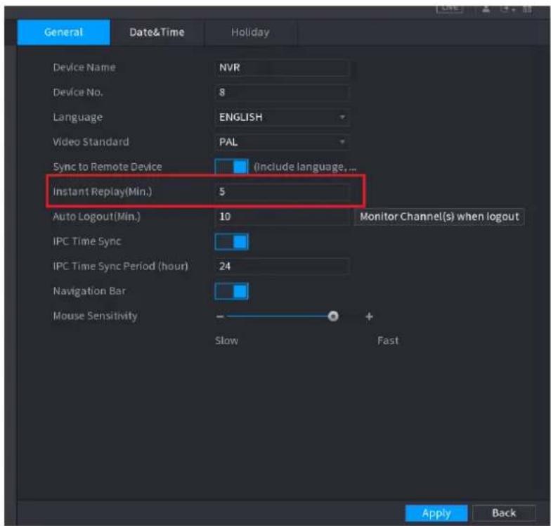
text_image
General Date&Time Holiday Device Name NVR Device No. 8 Language ENGLISH Video Standard PAL Sync to Remote Device (Include language... Instant Replay(Min.) 5 Auto Logout(Min.) 10 Monitor Channel(s) when logout IPC Time Sync 24 IPC Time Sync Period (hour) Navigation Bar Mouse Sensitivity Slow Fast Apply Back4.3.3.2 Digital zoom
You can zoom in specified zone of current channel so that you can view the details. It supports zoom in function of multiple-channel. It includes the following two ways:
- Click 📋, the icon switches to 🔒. Hold down the left mouse button to select the area you want to enlarge. The area is enlarged after the left mouse button is released.
- Point to the center that you want to enlarge, rotate the wheel button to enlarge the area.

- For some models, when the image is enlarged in the first way described previously, the selected area is zoomed proportionally according to the window.
The digital zoom interface is shown as in Figure 4-68. When the image is in the enlarged status, you can drag the image toward any direction to view the other enlarged areas. Right click mouse to cancel zoom and go back to the original interface.
Figure 4-68

text_image
Security camera panel with HBI logo and magnifying glass, showing status bar and warning sign
text_image
HBI
natural_image
Close-up of a door handle with a curved handle (no visible text or symbols)4.3.3.3 Instant backup
You can record the video of any channel and save the clip into a USB storage device.
By clicking, the recording is started. To stop recording, click this icon again. The clip is automatically saved into the connected USB storage device.
You can record the video of any channel and save the clip into a USB storage device.
4.3.3.4 Manual Snapshot
You can take one to five snapshots of the video and save into a USB storage device.
By clicking you can take snapshots. The snapshots are automatically saved into the connected USB storage device. You can view the snapshots on your PC.

To change the quantity of snapshots, select Main Menu > CAMERA > ENCODE > Snapshot, in the Manual Snap list, select the snapshot quantity.
4.3.3.5 Bidirectional talk
You can perform the voice interaction between the Device and the remote device to improve efficiency of emergency.
Step 1 Click button to start bidirectional talk function the icon now is shown as . Now the rest bidirectional talk buttons of digital channel becomes null too.
Step 2 Click again, you can cancel bidirectional talk.
4.3.3.6 Switch bit streams
Via this function, you can switch the channel main stream/sub stream according to current network bandwidth.
● M: Main stream. Its bit streams are big and definition is high. It occupies large network bandwidth suitable for video wall surveillance, storage and etc.
- S: Sub stream. Its definition is low but occupies small network bandwidth. It is suitable for general surveillance, remote connection and etc.
to switch the bit stream type of the main stream and sub stream.
M: Main stream.
- S: Sub stream. Some series products support two sub streams (S1, S2). Refer to "4.2.5.1 Encode" for detailed information.
4.3.3.7 Right-Click Menu
By right-clicking the menu, you can quickly access the corresponding functional interface and perform relevant operations, including entering the main menu, searching records and selecting screen split mode.
Right-click on the preview interface and the right-click menu is displayed. See Figure 4-69. Refer to Table 4-18 for detailed information.
The right-click menu is different for different models. The actual interface shall prevail.
Figure 4-69
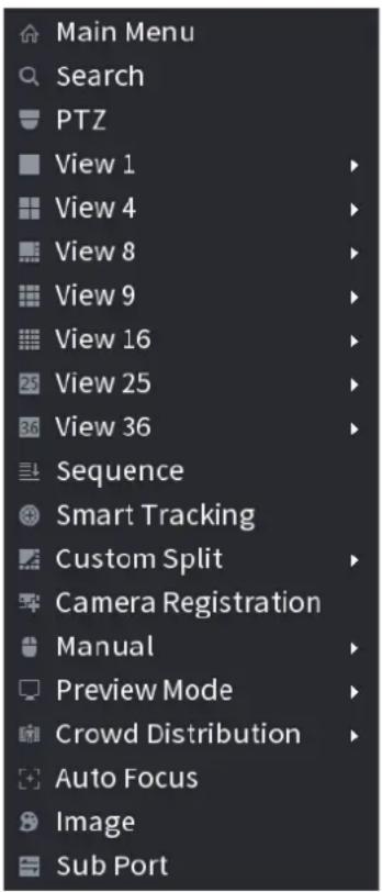
text_image
Main Menu Search PTZ View 1 View 4 View 8 View 9 View 16 View 25 View 36 Sequence Smart Tracking Custom Split Camera Registration Manual Preview Mode Crowd Distribution Auto Focus Image Sub PortTable 4-18
| Function | Description |
| Main Menu | Open Main Menu interface. |
| Search | Open the PLAYBACK interface where you can search and play back record files. For details, see "4.6 Playback and Search." |
| PTZ | Open the PTZ interface. For details, see "4.4 PTZ." |
| View1/4/8/9/16/25/36 | Configure the live view screen as a single-channel layout or multi-channel layout. |
| Sequence(View Layout) | Set customized screen split mode and channels. For details, see "4.3.4 Sequence." |
| Previous Screen | Click Previous Screen to go to the previous screen. For example, if you are using 4-split mode, the first screen is displaying the channel 1-4, click Next screen, you can view channel 5-8. |
| Next Screen | |
| Camera Registration | Open the CAMERA REGISTRATION interface. For details, see "4.1.4.4 Registration." |
| Manual | Select Record, you can configure the recording mode as Auto or Manual, or stop the recording. You can also enable or disable snapshot functionSelect Alarm Out, you can configure alarm output settings. |
| Preview Mode | There are two modes: regular/AI mode. |
| Crowd Distribution | Select enable/disable to start/stop crowd distribution function. |
| Auto focus | Click to realize auto focus function. Make sure the connected camera supports auto focus function. |
| Image | Click to modify the camera properties. For details, see "4.2.4 Image". |
| Sub Port | Click Sub Port, you can go to control the sub screen. |
4.3.4 Sequence
You can set customized view layout.

The preview layout restores default channel layout after Default operation.
Step 1 On the preview interface, right click mouse and then click Sequence.
The Sequence interface is displayed. See Figure 4-70.

- Enter edit view interface, device automatically switches to the max split amount mode.
- The channel list on the edit view interface displays the added camera channel
number and channel name.

ans camera is online.

camera is
offline.
- In case the channel amount has exceeded the device max split amount, the edit view interface can display the max screen number amount and current screen number.
Figure 4-70
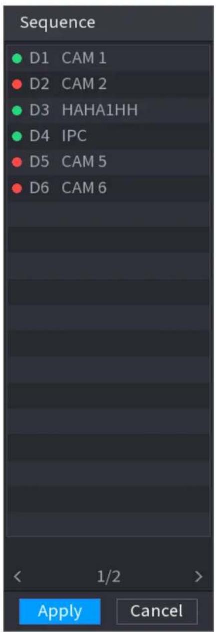
text_image
Sequence D1 CAM 1 D2 CAM 2 D3 HAHA1HH D4 IPC D5 CAM 5 D6 CAM 6 < 1/2 > Apply CancelStep 2 On the edit view interface, drag the channel to the desired window, or drag on the preview window to switch the position.
Check the channel number at the right bottom corner to view the current channel sequence. See Figure 4-71.
Figure 4-71
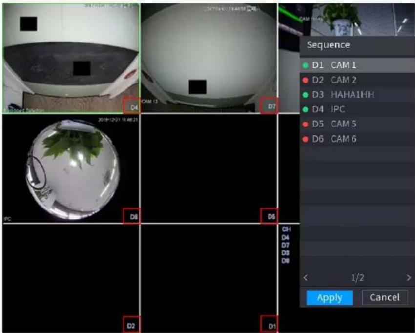
text_image
Sequence D1 CAM 1 D2 CAM 2 D3 HAHA1HH D4 IPC D5 CAM 5 D6 CAM 6 < 1/2 > Apply CancelStep 3 Click Apply to save current channel sequence.
After you change the channel sequence, click Cancel button or right click mouse, device pops up the dialogue box. See Figure 4-72.
- Click OK to save current settings.
- Click No to exit without saving the settings.
Figure 4-72
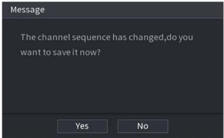
text_image
Message The channel sequence has changed,do you want to save it now? Yes No4.3.5 Fisheye (Optional)

This function is for some series products only.
4.3.5.1 Fisheye de-warp during preview interface
The fisheye camera (panoramic camera) has wide video of angle but its video is seriously
distorted. The de-warp function can present the proper and vivid video suitable for human eyes.
On the preview interface, select fisheye channel and then right click mouse, you can select fish eye. See Figure 4-73. You can set fisheye installation mode and display mode.

- For the non-fish eye channel, system pops up dialogue box to remind you it is not a fish eye channel and does not support de-warp function.
- If system resources are insufficient, system pops up the corresponding dialogue box too.
Figure 4-73
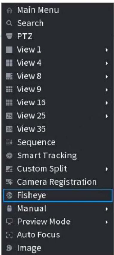
text_image
Main Menu Search PTZ View 1 View 4 View 8 View 9 View 16 View 25 View 36 Sequence Smart Tracking Custom Split Camera Registration Fisheye Manual Preview Mode Auto Focus ImageNow you can see an interface shown as in Figure 4-74. You can set fish eye installation mode and display mode. There are three installation modes: ceiling mount/wall mount/ground mount.

● The different installations modes have different de-warp modes.
- Some series products support 180° de-warp. 180° de-warp fisheye supports wall mount de-warp only. The actual product shall prevail.
Figure 4-74
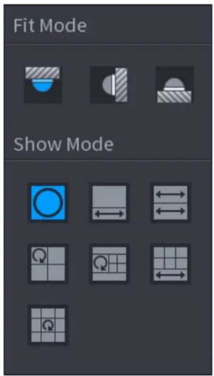
text_image
Fit Mode Show ModeRefer to the following sheet for detailed information. See Table 4-19.
Table 4-19
| Installation modes | Icon | Note | |
 | (Ceiling mount) |  | 360° panorama original view |
 | (Ground mount) |  | 1 de-warp window+1 panorama stretching |
 | 2 panorama stretching view | ||
 | 1 360° panorama view+3 de-warp windows | ||
 | 1 360° panorama view+4 de-warp windows | ||
 | 4 de-warp windows+1 panorama stretching | ||
 | 1 360° panorama view+8 de-warp windows | ||
| (Wall mount) |  | 360° panorama original view | |
 | Panorama stretching | ||
 | 1 panorama unfolding view+3 de-warp windows | ||
 | 1 panorama unfolding view +4 de warp windows | |
 | 1 panorama unfolding view +8 de warp windows |
Figure 4-75
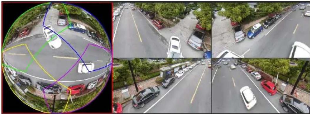
natural_image
Four-panel fisheye view of a multi-lane urban street scene with cars parked, no visible text or symbolsIn Figure 4-75, you can adjust the color pane on the left pane or use your mouse to change the position of the small images on the right pane to realize fish eye de-warp.
Operation: Use mouse to zoom in/zoom out, move, and rotate the image (Not for wall mount mode.)
4.3.5.2 Fish eye de-warp during playback
When playing back the fisheye record file, you can use de-warp function to adjust video.
Step 1 On the main menu, click Backup button.
Step 2 Select 1-window playback mode and corresponding fish eye channel, click to play.
Step 3 Right click the, you can go to the de-warp playback interface. For detailed information, refer to "4.3.5.1 Fisheye de-warp during preview interface".
4.3.6 Test Temperature
When connecting to the front-end device that supports temperature detection, system can display instant temperature.

- This function may collect the human temperature in the surveillance video, be careful!
● This function is for some series products only.
Preparations
Refer to "4.16.1 Display" to enable test temperature function.
On the preview window, click any position on the thermal channel video. The interface is shown as below. See Figure 4-76.
Figure 4-76
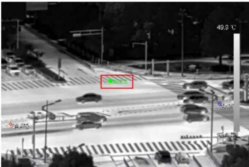
text_image
49.9 °C 15.810 37.6104.3.7 AI Preview Mode
When you select AI mode, the system displays information of human face, personnel, vehicle and non-motor vehicle on the right side of the preview interface, and it supports to play back records and display feature attributes.

You need to enable face detection, body detection, vehicle detection and non-motor vehicle detection to support this function. For details, see "4.7.2.5 Video Structuring (Metadata)."
Step 1 Right click to select Preview Mode > AI Mode.
The AI preview interface is displayed. See Figure 4-77.
Figure 4-77
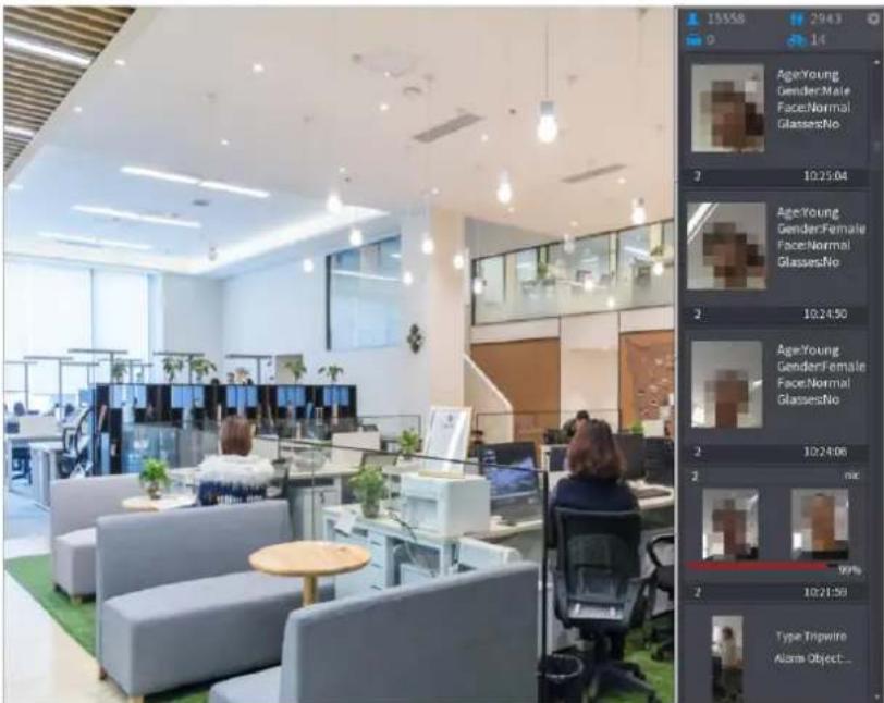
text_image
15358 2943 Age:Young Gender:Male Face:Normal GlassesNo 2 10:25:04 Age:Young Gender:Female Face:Normal GlassesNo 2 10:24:50 Age:Young Gender:Female Face:Normal GlassesNo 2 10:24:06 2 max 99% 2 10:21:58 Type Tripwire Alarms Object...Step 2 (Optional) Double-click the image on the right to play the corresponding video.
Step 3 Click

The Properties interface is displayed. See Figure 4-78.
Figure 4-78
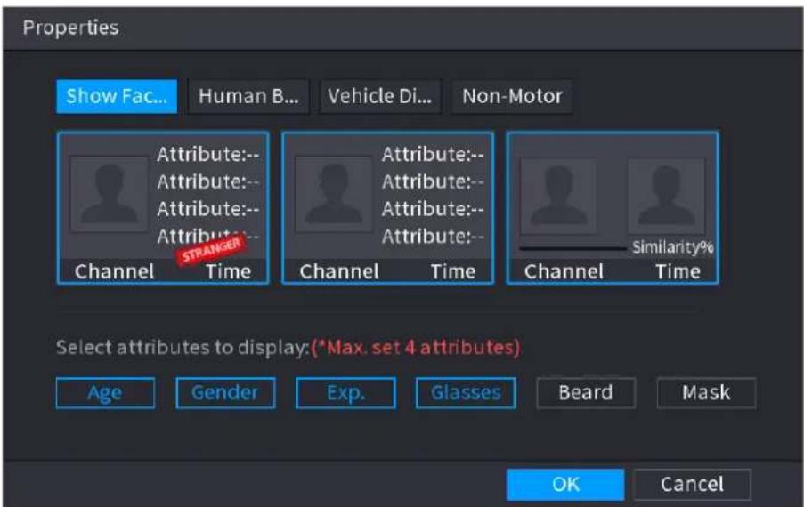
text_image
Properties Show Fac... Human B... Vehicle Di... Non-Motor Attribute:-- Attribute:-- Attribute:-- STRANGER Channel Time Channel Time Channel Similarity% Channel Time Channel Time Select attributes to display:(*Max. set 4 attributes) Age Gender Exp. Glasses Beard Mask OK CancelStep 4 (Optional) Click Show Face List and select attributes to display, including age, gender, expression, glasses, beard and mask.
Step 5 (Optional) Click Human Body Detection and select attributes to display, including top, pants, hat, bag, bag style, umbrella, age and gender. See Figure 4-79.
Figure 4-79
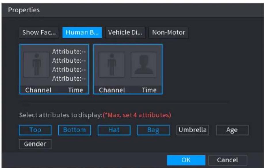
text_image
Properties Show Fac... Human B... Vehicle Di... Non-Motor Attribute:-- Attribute:-- Attribute:-- Attribute:-- Channel Time Channel Time Select attributes to display:(*Max. set 4 attributes) Top Bottom Hat Bag Umbrella Age Gender OK CancelStep 6 (Optional) Click Vehicle Display and select attributes to display, including vehicle logo, vehicle color, vehicle model, plate recognition, plate color, seatbelt, call, vehicle decorations and countries & regions. See Figure 4-80.
Figure 4-80
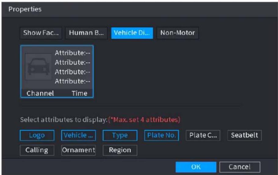
text_image
Properties Show Fac... Human B... Vehicle Di... Non-Motor Attribute:-- Attribute:-- Attribute:-- Attribute:-- Channel Time Select attributes to display: (*Max. set 4 attributes) Logo Vehicle ... Type Plate No. Plate C... Seatbelt Calling Ornament Region OK CancelStep 7 (Optional) Click Non-Motor and select attributes to display, including color, type and people number. See Figure 4-81.
Figure 4-81
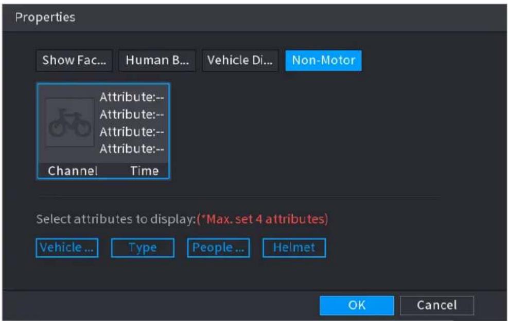
text_image
Properties Show Fac... Human B... Vehicle Di... Non-Motor Attribute:-- Attribute:-- Attribute:-- Attribute:-- Channel Time Select attributes to display:(*Max. set 4 attributes) Vehicle ... Type People ... Helmet OK CancelStep 8 Click OK to complete the setting.

The system can display four attributes at most.
4.4 PTZ
PTZ is a mechanical platform that carries a camera and a protective cover and performs overall control remotely. A PTZ can move in both horizontal and vertical direction to provide all-around view to the camera.

Before you control the PTZ, make sure the PTZ decoder and the NVR network connection is OK.
4.4.1 PTZ Settings
You can set different PTZ parameters for local type and remote type. Before you use local PTZ, make sure you have set PTZ protocol; otherwise you cannot control the local PTZ.
- Local: The PTZ device connects to the NVR via the cable.
- Remote: The PTZ device connects to the NVR via the network.

This function is for some series products only.
Step 1 Select Main menu > CAMERA > PTZ.
Step1 The PTZ interface is displayed. See Figure 4-82 (Local) or Figure 4-83 (Remote).
Figure 4-82
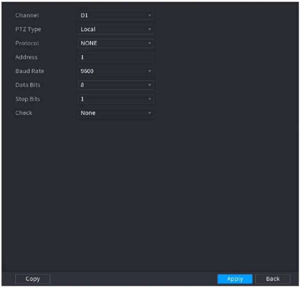
text_image
Channel D1 PTZ Type Local Protocol NONE Address 1 Baud Rate 9600 Data Bits 8 Stop Bits 1 Check None Copy Apply BackFigure 4-83
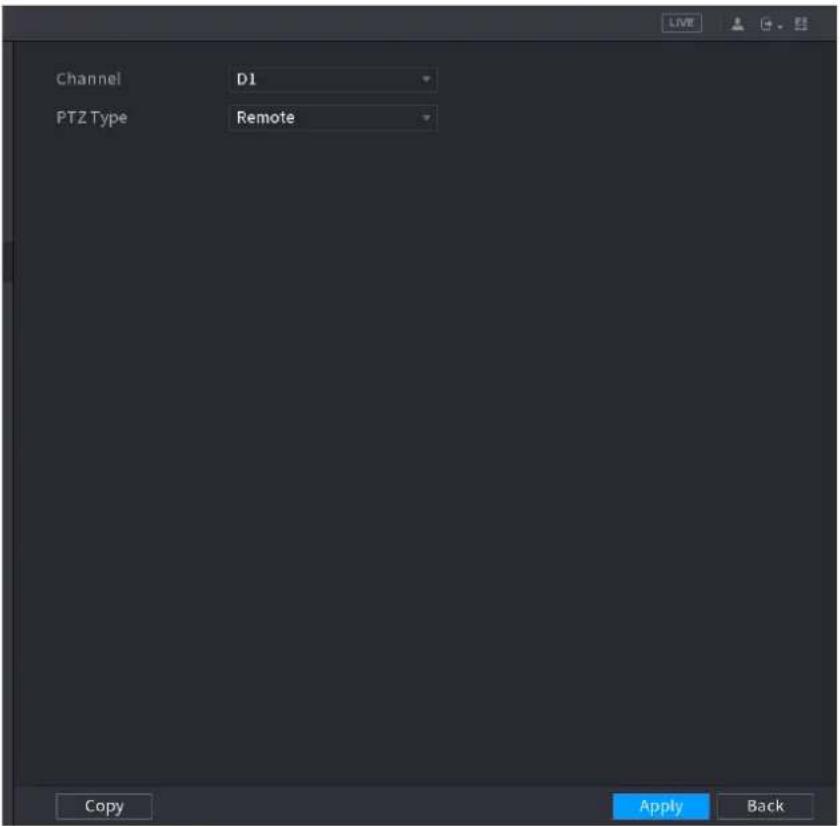
text_image
Channel D1 PTZ Type Remote Copy Apply BackStep 2 Configure parameters. See Table 4-20.
Table 4-20
| Parameter | Description |
| Channel | In the Channel list, select the channel that you want to connect the PTZ camera to. |
| PTZ Type | Local: Connect through RS-485 port.Remote: Connect through network by adding IP address of PTZ camera to the Device. |
| Protocol | In the Protocol list, select the protocol for the PTZ camera such as PELCOD. |
| Address | In the Address box, enter the address for PTZ camera. The default is 1.The entered address must be the same with the address configured on the PTZ camera; otherwise the system cannot control PTZ camera. |
| Baud rate | In the Baud rate list, select the baud rate for the PTZ camera. The default is 9600. |
| Data Bits | The default is 8. |
| Stop Bits | The default is 1. |
| Parity | The default is NONE. |
Step 3 Click Apply.
4.4.2 PTZ Control
PTZ control panel performs the operations such as directing camera in eight directions,
adjusting zoom, focus and iris settings, and quick positioning.
Basic PTZ Control Panel
Right-click on the live view screen and then select PTZ. The PTZ control panel is displayed. See Figure 4-84.
Figure 4-84
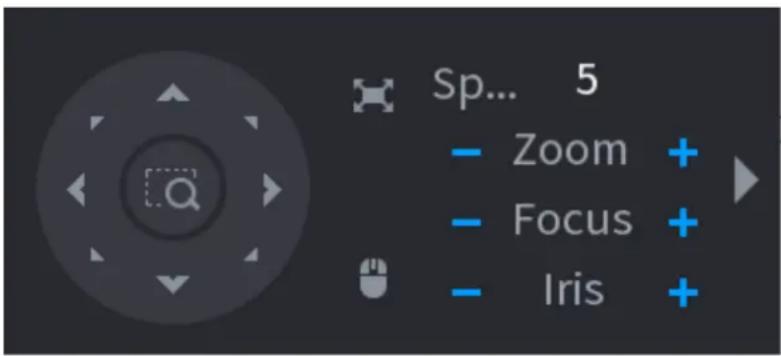
text_image
Sp... 5 - Zoom + - Focus + - Iris +
- The gray button means system does not support current function.
- For some series products, the PTZ function is valid in one-window mode.
Table 4-21
| Parameter | Description |
| Speed | Controls the movement speed. The bigger the value is, the faster the movement will be. |
| Zoom |   |
| Focus |   |
| Iris |   |
| PTZ movement | Supports eight directions. |
 | Fast positioning button. Positioning: Click to enter the fast positioning screen, and then click anywhere on the live view screen, the PTZ will turn to this point and move it to the middle of the screen. Zooming: On the fast positioning screen, drag to draw a square onthe view. The square supports zooming.• Dragging upward is to zoom out, and dragging downward is to zoom in.• The smaller the square, the larger the zoom effect.This function is for some series products only and can only be controlled through mouse operations. |
 | Click  can control the four directions (left, right, up, and down)PTZ movement through mouse operation. can control the four directions (left, right, up, and down)PTZ movement through mouse operation. |
 | Click  open the expanded PTZ control panel. open the expanded PTZ control panel. |
Expanded PTZ Control Panel
On the basic PTZ control panel, click to open the expanded PTZ control panel to find more options. See Figure 4-85.
Figure 4-85
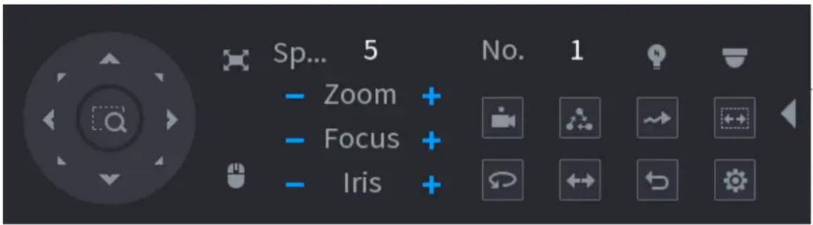
text_image
Sp... 5 - Zoom + - Focus + - Iris + No. 1
- The functions with buttons in gray are not supported by the system.
- Right-click once to return to the interface of PTZ basic control panel.
Table 4-22
| Icon | Function | Icon | Function |
 | Preset |  | Auto Pan |
 | Tour |  | Flip |
 | Pattern |  | Reset |
 | Auto scan |  | Click the AUX Config icon to open the PTZ functions settings interface. |
| [8WGS] | AUX Switch | [TACK] | Click the Enter Menu icon to open the MENU OPERATION interface. |
4.4.3 Configuring PTZ Functions
4.4.3.1 Configuring Presets
Step 1 On the Expanded PTZ Control Panel, click
The Preset interface is displayed. See Figure 4-86.
Figure 4-86
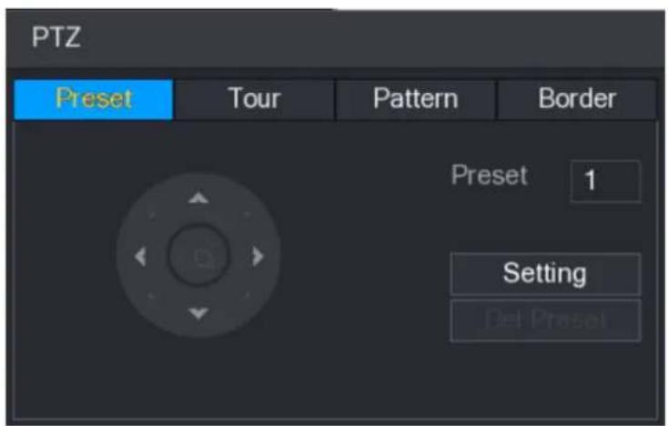
text_image
PTZ Preset Tour Pattern Border Preset 1 Setting Del PresetStep 4 Click the direction arrows to the required position.
Step 5 In the Preset box, enter the value to represent the required position.
Step 6 Click Setting to complete the preset settings.
4.4.3.2 Configuring Tours
Step 1 On the Expanded PTZ Control Panel, click

The PTZ interface is displayed.
Step 2 Click the Tour tab.
The Tour tab is displayed. See Figure 4-87.
Figure 4-87
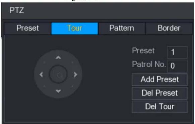
text_image
PTZ Preset Tour Pattern Border Preset 1 Patrol No. 0 Add Preset Del Preset Del TourStep 3 In the Patrol No. box, enter the value for the tour route.
Step 4 In the Preset box, enter the preset value.
Step 5 Click Add Preset.
A preset will be added for this tour.

- You can repeat adding more presets.
- Click Del Preset to delete the preset for this tour. This operation can be repeated to delete more presets. Some protocols do not support deleting.
4.4.3.3 Configuring Patterns
Step 1 On the Expanded PTZ Control Panel, click

The PTZ interface is displayed.
Step 2 Click the Pattern tab.
The Pattern interface is displayed. See Figure 4-88.
Figure 4-88
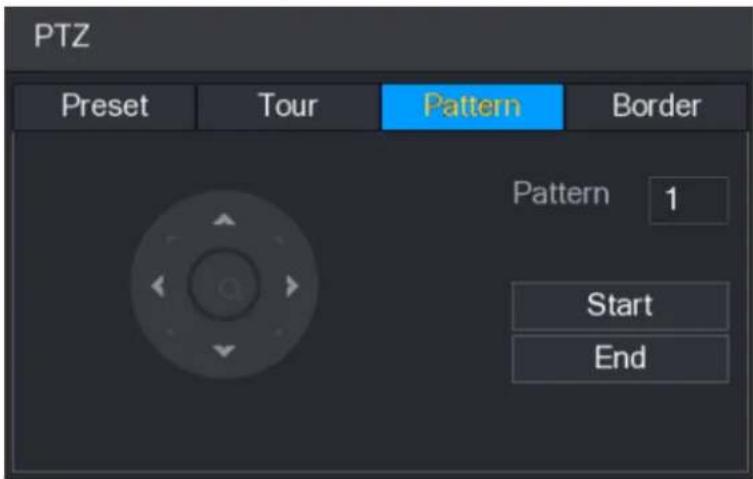
text_image
PTZ Preset Tour Pattern Border Pattern 1 Start EndStep 3 In the Pattern box, enter the value for pattern.
Step 4 Click Start to perform the directions operations. You can also go to the PTZ Control Panel to perform the operations of adjusting zoom, focus, iris, and directions.
Step 5 On the PTZ interface, click End to complete the settings.
4.4.3.4 Configuring AutoScan
Step 1 On the Expanded PTZ Control Panel, click

The PTZ interface is displayed.
Step 2 Click the Border tab.
The Border interface is displayed. See Figure 4-89.
Figure 4-89
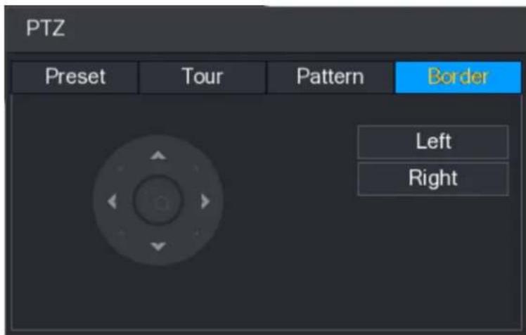
text_image
PTZ Preset Tour Pattern Border Left RightStep 3 Click the direction arrows to position the left and right borders.
4.4.4 Calling PTZ Functions
After you have configured the PTZ settings, you can call the PTZ functions for monitoring from the Expanded PTZ Control Panel. See Figure 4-90.
Figure 4-90
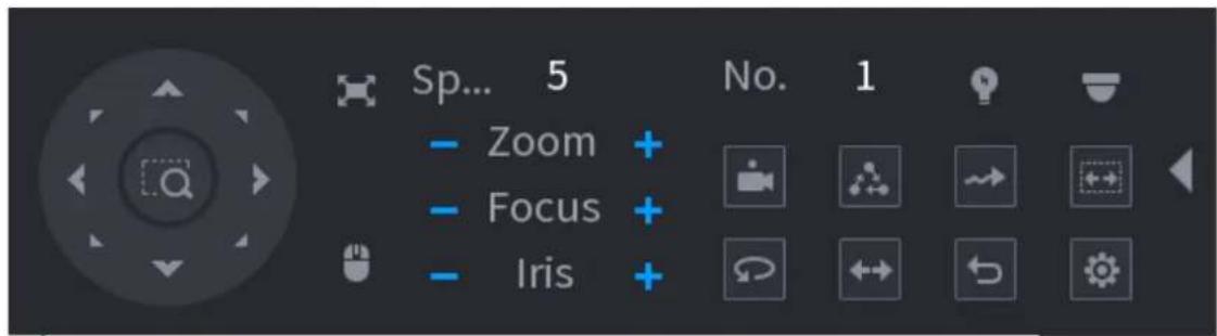
text_image
Sp... 5 - Zoom + - Focus + - Iris + No. 14.4.4.1 Calling Presets
Step 1 On the Expanded PTZ Control Panel, in the No. box, enter the value of the preset that you want to call.
Step 2 Click to call the preset.
Step 3 Click again to stop calling the preset.
4.4.4.2 Calling Tours
Step 1 On the Expanded PTZ Control Panel, in the No. box, enter the value of the tour that you want to call.
Step 2 Click to call the tour.
Step 3 Click again to stop calling the tour.
4.4.4.3 Calling Patterns
Step 1 On the Expanded PTZ Control Panel, in the No. box, enter the value of the pattern that you want to call.
Step 2 Call to call the pattern.
The PTZ camera moves according to the configured pattern repeatedly.
Step 3 Click

ain to stop calling the pattern.
4.4.4.4 Calling AutoScan
Step 1 On the Expanded PTZ Control Panel, in the No. box, enter the value of the border that you want to call.
Step 2 Click

The PTZ camera performs scanning according to the configured borders.
Step 3 Click

ain to stop auto scanning.
4.4.4.5 Calling AutoPan
Step 1 On the Expanded PTZ Control Panel, click

start moving in horizontal direction.
Step 2 Click

ain to stop moving.
4.4.4.6 Using AUX Button
On the Expanded PTZ Control Panel, click , the AUX setting interface is displayed. See
Figure 4-91.
In the Direct Aux list, select the option that corresponds to the applied protocol.
In the Aux Num box, enter the number that corresponds to the AUX switch on the decoder.
Figure 4-91
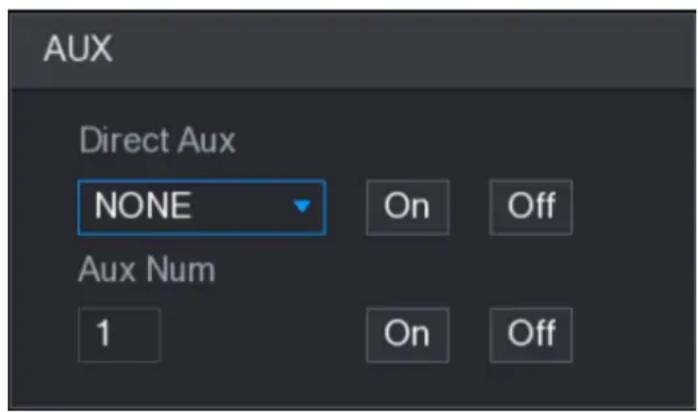
text_image
AUX Direct Aux NONE On Off Aux Num 1 On Off4.5 Record File
Device adopts 24-hour continuous record by default. It supports customized record period and record type. Refer to "4.1.4.6 Schedule" for detailed information.
4.6 Playback and Search
4.6.1 Instant Playback
You can view the record file of previous 5 to 60 minutes. Refer to "4.3.2 Navigation bar" for instant playback information.
4.6.2 Search Interface
You can search and playback the record fine on the NVR.
Select Main Menu > PLAYBACK, or on the preview interface right click mouse and then select Search, you can go to the following interface. See Figure 4-92.

The following figure for reference only.
Figure 4-92
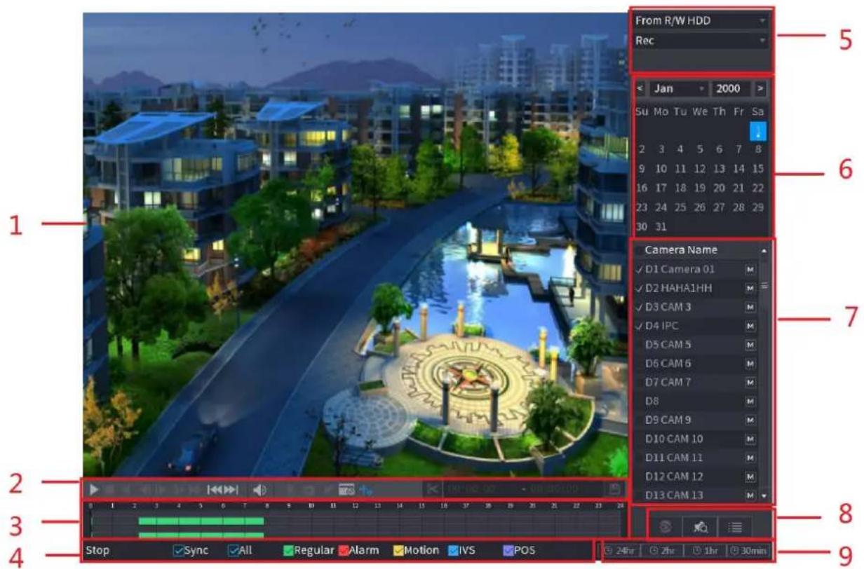
text_image
From R/W HDD Rec Jan 2000 Su Mo Tu We Th Fr Sa 2 3 4 5 6 7 8 9 10 11 12 13 14 15 16 17 18 19 20 21 22 23 24 25 26 27 28 29 30 31 Camera Name ✓ D1 Camera 01 M ✓ D2 HAHA1HH M ✓ D3 CAM 3 M ✓ D4 IPC M D5 CAM 5 M D6 CAM 6 M D7 CAM 7 M D8 M D9 CAM 9 M D10 CAM 10 M D11 CAM 11 M D12 CAM 12 M D13 CAM 13 M Stop Sync All Regular Alarm Motion IVS POS 24hr 2hr 1hr 30minTable 4-23
| No. | Function | Description |
| 1 | Display Window | Display the searched recorded video or picture. It supports playing in single-channel, 4-channel, 9-channel, and 16-channel simultaneously.When playing back in a single channel mode, hold down the left mouse button to select the area that you want to enlarge. The area is enlarged after the left mouse button is released. To exit the enlarged status, right-click on the image. |
| 2 | PlaybackControls Bar | Playback control buttons. Refer to "4.6.2.1 Playback Control" for detailed information. |
| Clip | Click to edit the record file and then save specified footages.Refer to "4.6.2.3 Clip" for detailed information. | |
| Backup | Click to backup record. Refer to "4.6.2.4 Record Backup" for detailed information. | |
| 3 | Time Bar | Display the type and time period of the current recorded video.In the 4-channel layout, there are four time bars are displayed; in the other view layouts, only one time bar is displayed.Click on the colored area to start playback from a certain time.In the situation when you are configuring the settings, rotate the wheel button on the time bar, the time bar is zooming in from 0. In the situation when playback is ongoing, rotate the wheel button on the time bar, the time bar is zooming from the time point where the playback is located.Time bar colors: Green indicates general type; Red indicates external alarm; Yellow indicates motion detection; Blue indicates intelligent events; Purple indicates POS events.For some models, when you are clicking on the blank area in the time bar, the system automatically jumps to the next time point where there is a recorded video located. |
| 4 | Play Status | Includes two playback status: Play and Stop. |
| Sync | Select the Sync check box to simultaneously play recorded videos of different channels in the same period in multi-channel view. | |
| Record type | Select the check box to define the recording type to search for. | |
| 5 | Search type | Select the content to play back: Record, PIC, Splice Playback. For details about the selecting search type, refer to "4.6.2.2 Search Type" for detailed information. |
| 6 | Calendar | Click the date that you want to search, the time bar displays the corresponding record.The dates with record or snapshot have a small solid circle under the date. |
| 7 | View Layout and Channel Selection | In the CAM NAME list, select the channel(s) that you want to play back.The window split is decided by how you select the channel(s). For example, if you select one channel, the playback is displayed in the single-channel view; if you select two to four channels, the playback is displayed in the four-channel view. The maximum is eight channels.Click to  tch the streams. indicates main stream, and tch the streams. indicates main stream, and  icates sub stream. icates sub stream. |
| 8 | List Display | This area includes Mark List and File List.Different series products have different functions. The icons displayed may vary. The actual product shall prevail.Click the Mark List button, the marked recorded video list is displayed. Double-click the file to start playing.•  : Click the File List button, the searched recorded video list is displayed. You can lock/unlock the files. Refer to "4.6.7 File List " for detailed information. • : Click the File List button, the searched recorded video list is displayed. You can lock/unlock the files. Refer to "4.6.7 File List " for detailed information. •  ye dewarp. It is to display the dewarp fisheye video. Refer to "4.3.5.2 Fish eye de-warp during playback" for detailed information. ye dewarp. It is to display the dewarp fisheye video. Refer to "4.3.5.2 Fish eye de-warp during playback" for detailed information. |
| 14 | Time Bar Unit | You can select 24hr, 2hr, 1hr, or 30min as the unit of time bar. The time bar display changes with the setting. |

All the operations here (such as playback speed, channel, time and progress) have relationship with hardware version. Some series NVRs do not support some functions or playback speeds.
4.6.2.1 Playback Control
The playback control interface is shown as below. See Figure 4-93.
Figure 4-93

text_image
Media player control bar with playback, pause, and audio iconsRefer to the following sheet for more information. See Table 4-24.
Table 4-24
| Icon | Function | |
 | Play/PauseIn slow play mode, click it to switch between play/pause. | |
 | StopWhen playing back, click to stop current playback process. | |
 | Backward playIn normal play mode, left click the button, the file begins backward play. Click it again to pause current play.In backward play mode, click or to restore normal play. | |
 | Display previous frame/next frame.When pause the normal playback file, click or to playback frame by frame.In frame by frame playback mode, click or to resume normal playback mode. | |
 | Slow playIn playback mode, click it to realize various slow play modes such as slow play 1, slow play 2, and etc. | |
| Icon | Function | |
 | Fast forwardIn playback mode, click to realize various fast play modes such as fast play 1,fast play 2 and etc. | |
| [WOYZ] | Adjust the volume of the playback. | |
 | Smart search .Refer to "4.6.3 Smart Search Playback" for detailed information. | |
 | Click the snapshot button in the full-screen mode, the system can snapshot 1 picture.System supports custom snap picture saved path. Connect the peripheral device first, click snap button on the full-screen mode, you can select or create path. Click Start button, the snapshot picture can be saved to the specified path. | |
 | Mark button.This function is for some series product only. Make sure there is a mark button in the playback control pane.Refer to "4.6.4 Mark Playback" for detailed information. | |
 | Display/hide POS information.In 1-channel playback mode, you can click it to display/hide POS information on the video. | |
 | In 1-channel playback mode, click it to enable/disable display IVS rule information on the video.This function is for some series only. | |
4.6.2.2 Search Type
You can search the recorded videos, splice, or snapshots from HDD or external storage device.
- From R/W HDD: Recorded videos or snapshots playback from HDD of the Device. See Figure 4-94.
Figure 4-94
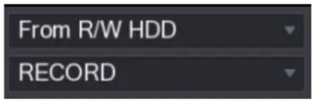
text_image
From R/W HDD RECORD- From I/O Device: Recorded videos playback from external storage device. See Figure 4-95.
Click Browse, select the save path of recorded video file that you want to play. Double-click
the video file or click ▶ to start playing.
Figure 4-95
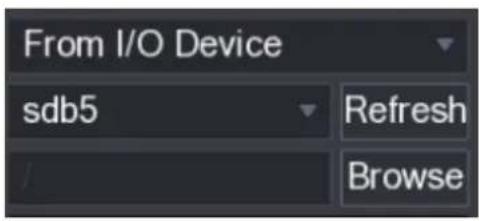
text_image
From I/O Device sdb5 Refresh Browse4.6.2.3 Clip
This function allows you to clip some footages to a new file and then save it to the USB device. See Figure 4-96. Follow the steps listed below.
Step 1 Select a record first and then click to playback.
Step 2 Select a time at the time bar and then click to start clip,
Step 3 Select a time at the time bar and then click to stop clip,
Step 4 Click system pops up dialogue box to save the clip file.
Figure 4-96

text_image
00:00:00 - 00:00:00
- Clip function is for one-channel/multiple-channel.
● Max save 1024 files at the same time.
● This function is not for the file already checked in the file list.
4.6.2.4 Record Backup
This function is to backup files you checked in the file list, or the file you just clip.
Step 1 Select the recorded video file that you want to back up. You can select the following two types of files:
- Recorded video file: Click the File List area is displayed. Select the file(s) that you want to back up.
- Saves the clip footages as a record file.
Step 2 Click, the BACKUP interface is displayed. See Figure 4-97.
Figure 4-97
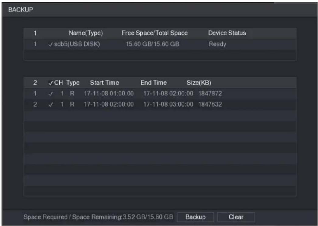
text_image
BACKUP 1 Name(Type) Free Space/Total Space Device Status 1 √ sdb5(USB DISK) 15.60 GB/15.60 GB Ready 2 √ CH Type Start Time End Time Size(KB) 1 √ 1 R 17-11-08 01:00:00 17-11-08 02:00:00 1847872 2 √ 1 R 17-11-08 02:00:00 17-11-08 03:00:00 1847632 Space Required / Space Remaining:3.52 GB/15.60 GB Backup ClearStep 3 Click Backup to begin the process.
4.6.3 Smart Search Playback

This function is for some series product only.
During playback process, it can analyze the motion detect zone in the scene and give the analysis result.
This function is for channel that already enabled motion detect function (Main Menu > ALARM > VIDEO DETECT > Motion Detect).
Step 1 Select a channel to playback video and then click . You can view the grids on the playback video.

● This function is for one-channel playback mode.
- If you are in multiple-channel playback mode, double-click a channel first to switch to one-channel playback mode.
Step 2 Left click mouse and then drag to select smart search zones(22*18 (PAL), 22*15 (NTSC)).
Step 3 Click

detect record footages.
Step 4 Click

again to stop smart search function.

can view the grids on the

● The motion detect region cannot be the full screen zone.
- The motion detect region adopts the current whole play pane by default.
- Selects the other file on the list, system begins playing the motion detect footages of other file.
- The time bar unit switch, backward play, frame by frame are null when system is playing motion detect file.
4.6.4 Mark Playback
When you are playback record, you can mark the record when there is important information. After playback, you can use time or the mark key words to search corresponding record and then play. It is very easy for you to get the important video information.
- Add Mark
When system is playback, click Mark button, you can go to the following interface. See Figure 4-98.
Figure 4-98
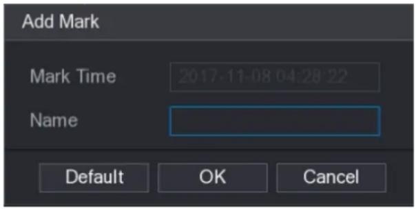
text_image
Add Mark Mark Time 2017-11-08 04:28:22 Name Default OK Cancel- Playback Mark
During 1-window playback mode, click mark file list button in Figure 4-92, you can go to mark file list interface. Double-click one mark file, you can begin playback from the mark time.
● Play before mark time
Here you can set to begin playback from previous N seconds of the mark time.

Usually, system can playbacks previous N seconds record if there is such kind of record file. Otherwise, system playbacks from the previous X seconds when there is such as kind of record.
- Mark Manager
Click the mark manager button on the Search interface (Figure 4-92); you can go to
Manager interface. See Figure 4-99. System can manage all the record mark information of current channel by default. You can view all mark information of current channel by time.
Figure 4-99
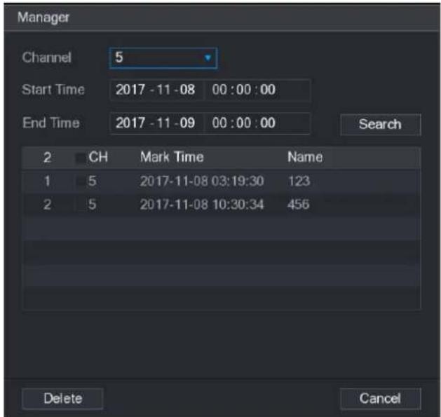
text_image
Manager Channel 5 Start Time 2017-11-08 00:00:00 End Time 2017-11-09 00:00:00 Search 2 CH Mark Time Name 1 5 2017-11-08 03:19:30 123 2 5 2017-11-08 10:30:34 456 Delete Cancel- Modify
Double-click one mark information item, you can see system pops up a dialogue box for you to change mark information. You can only change mark name here.
- Delete
Here you can check the mark information item you want to delete and then click Delete button, you can remove one mark item.

- After you go to the mark management interface, system needs to pause current playback. System resume playback after you exit mark management interface.
- If the mark file you want to playback has been removed, system begins playback from the first file in the list.
4.6.5 Playback Image
Here you can search and play the image. Follow the steps listed below.
Step 1 Select Main Menu > PLAYBACK, or on the preview window right click mouse and then click Search, you can go to the Search interface.
Step 2 At the top right corner, select image and then input playback interval.
Step 3 Select date and channel, click to play.
4.6.6 Splice Playback
You can clip the recorded video files into splices and then play back at the same time to save your time.

This function is for some series products only.
Step 1 Select Main Menu > PLAYBACK, the PLAYBACK interface is displayed.
Step 2 In the Search Type list, select Splice Playback; In the Split Mode list, select 4, 9, or 16. See Figure 4-100.
Figure 4-100

text_image
From R/W HDD Splice Playback 4Step 3 In the Calendar area, select a date.
Step 4 In the CAM NAME list, select a channel.

Only single-channel supports this function.
Step 5 Start playing back splices. See Figure 4-101.
- Click, the playback starts from the beginning.
- Double-click anywhere on the time bar, the playback starts from where you click.
Figure 4-101

line
| Point | Value | |---|---| | 1 | 0.35 | | 2 | 0.19 | | 3 | 0.15 | | 4 | 0.28 | | 5 | 0.25 | | 6 | 0.39 | | 7 | 0.35 | | 8 | 0.43 | | 9 | 0.45 | | 10 | 0.58 | | 11 | 0.55 | | 12 | 1 |4.6.7 File List
Click , system displays file list. It displays the first channel of the record. See Figure 4-102.
Figure 4-102
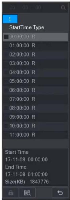
text_image
1 StartTime Type 00:00:00 R 01:00:00 R 02:00:00 R 03:00:00 R 04:00:00 R 05:00:00 R 06:00:00 R 07:00:00 R 08:00:00 R 09:00:00 R 10:00:00 R 11:00:00 R Start Time 17-11-08 00:00:00 End Time 17-11-08 01:00:00 Size(KB) 1847776- Check a file name, double-click the file or click

- Input accurate time at the top column, you can search records of current day.
- System max displays 128 record files in one list.
- Click to go back to the calendar/channel selection interface.
Lock or Unlock File
- To lock the recorded video, on the File List interface, select the check box of the recorded
video, and then click The locked video will not be overwritten.
- To view the locked information, click 📄, the FILE LOCKED interface is displayed.
The recorded video that is under writing or overwriting cannot be locked.
- To unlock the recorded video, in the FILE LOCKED interface, select the video, and then click Unlock. See Figure 4-103.
Figure 4-103
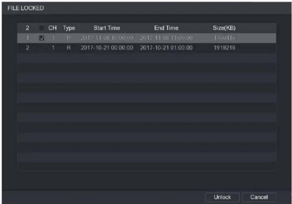
text_image
FILE LOCKED 2 CH Type Start Time End Time Size(KB) 1 ✓ 1 B 2017 11 08 10:00:00 2017 11 08 11:00:00 1150416 2 ✓ 1 R 2017-10-21 00:00:00 2017-10-21 01:00:00 1919216 Unlock Cancel4.6.8 Other Aux Functions
4.6.8.1 Digital Zoom
In 1-window playback mode, left click mouse to select any zone on the screen, you can zoom in current zone. Right click mouse to exit.
4.6.8.2 Switch Channel
- During playback mode, select from the dropdown list to switch playback channel.
- The smart search channel does not support this function either.
- When system is playing back the record file, click the number button at the front panel, system begins playing the record file of selected channel dated the same time.
4.7 AI
4.7.1 AI Search
You can search the record file on the NVR and filter the record file meets the corresponding rule. It is suitable for you to play the specified file.

This series NVR products support playback the AI by camera file only. AI by camera means the connected camera does all the AI analytics, and then gives the results to the NVR.
4.7.1.1 Face Detection
You can search the detected faces and play back.
Step 1 Select Main Menu > AI > SMART SEARCH > FACE DETECTION.
The FACE DETECTION interface is displayed. See Figure 4-104.
Figure 4-104
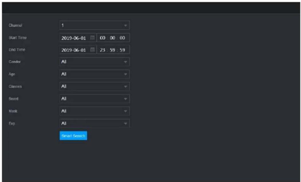
text_image
Channel 1 Start Time 2019-06-01 00 00 00 End Time 2019-06-01 23:59:59 Gender All Age All Classes All Board All Mask All Exp All Smart SearchStep 2 Select the channel, enter the start time and end time, and set for the gender, age, glasses, beard, and mask. Click Smart Search. The results are displayed. See Figure 4-105.

For privacy reason, the human face in the image is pixelated. The actual image is clear.
Figure 4-105
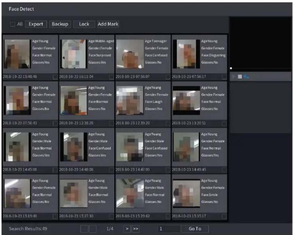
text_image
Face Detect All Export Backup Lock Add Mark Age Young Gender: Female Face Normal Glasses Yes Age Middle-aged Gender: Female Face Surprised Glasses Yes Age Teenager Gender: Female Face Confused Glasses No Age Young Gender: Female Face Disgusting Glasses No 2018-10-22 15:48:48 2018-10-22 16:11:04 2018-10-23 07:56:07 2018-10-23 07:56:17 Age Young Gender: Female Face Normal Glasses No Age Young Gender: Female Face Normal Glasses No Age Young Gender: Female Face Laugh Glasses Yes Age Young Gender: Female Face Normal Glasses No 2018-10-23 07:56:43 2018-10-23 12:38:28 2018-10-23 12:39:20 2018-10-23 13:20:51 Age Young Gender: Male Face Normal Glasses Yes Age Young Gender: Male Face Confused Glasses Yes Age Young Gender: Male Face Confused Glasses Yes Age Young Gender: Female Face Normal Glasses Yes 2018-10-23 14:45:06 2018-10-23 14:46:08 2018-10-23 14:47:05 2018-10-23 14:49:45 Age Young Gender: Female Face Normal Glasses No Age Young Gender: Male Face Normal Glasses No Age Young Gender: Male Face Normal Glasses No Age Young Gender: Female Face Smile Glasses No 2018-10-23 15:19:40 2018-10-23 15:27:30 2018-10-23 15:29:42 2018-10-23 15:35:17 Search Results:49 1/4 > >> 1 Go ToStep 3 Select the face that you want to play back. The picture with registered information is displayed.
You can also do the following operations to the recorded files.
- To back up the recorded files to the external storage device, select files, click Backup, select the save path and file type, and then click Start. See Figure 4-106.
Figure 4-106
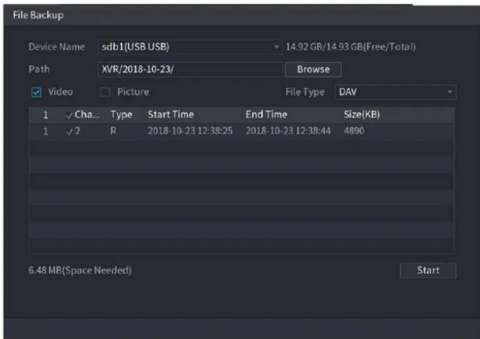
text_image
File Backup Device Name:sdb1(USB USB) 14.92 GB/14.93 GB(Free/Total) Path XVR/2018-10-23/ Browse ✓ Video Picture File Type DAV 1 ✓ Cha... Type Start Time End Time Size(KB) 1 ✓ 2 R 2018-10-23 12:38:25 2018-10-23 12:38:44 4890 6.48 MB(Space Needed) Start- To lock the files to make it unable to be overwritten, select the files, and then click Lock.
• To add a mark to the file, select the files and then click Add Mark. - Go to Face Properties and Person Details to view detailed information.
4.7.1.2 Face Recognition
System can search and compare the human face on the video with the face image on the database, and playback the corresponding record file.
The AI search includes two ways: Search by attributes and search by image.

This function is for some series products only.
4.7.1.2.1 Searching by Attributes
Step 1 Select Main Menu > AI > SMART SEARCH > FACE RECOGNITION > Search by Attributes.
The Search by Attributes interface is displayed. See Figure 4-107.
Figure 4-107
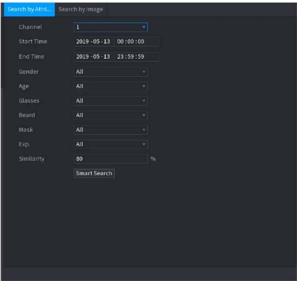
text_image
Search by Attri... Search by Image Channel 1 Start Time 2019 -05 -13 00:00:00 End Time 2019 -05 -13 23:59:59 Gender All Age All Glasses All Beard All Mask All Exp. All Similarity 80 % Smart SearchStep 2 Select the channel and set the parameters such as start time, end time, gender, age, glasses, beard, mask, and similarity according to your requirement.
Step 3 Click Smart Search.
The search result is displayed. See Figure 4-108.

The human face in the image is pixelated. The actual image is clear.
Figure 4-108
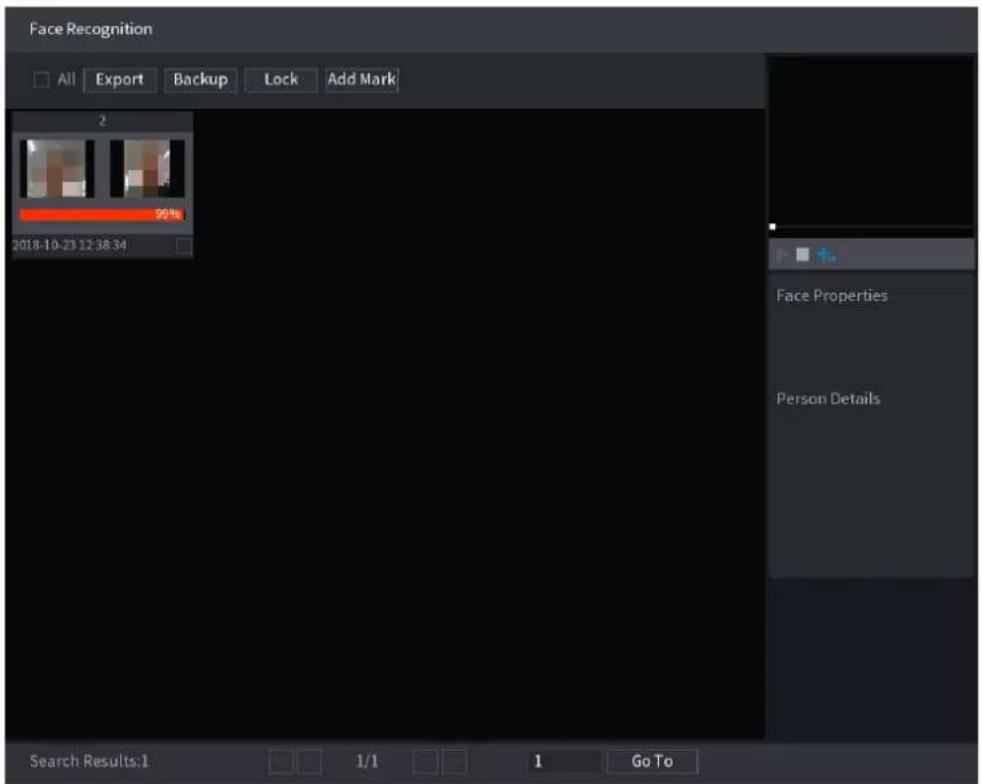
text_image
Face Recognition All Export Backup Lock Add Mark 2 99% 2018-10-23 12:38:34 Face Properties Person Details Search Results:1 1/1 1 Go ToStep 4 Click the picture that you want to play back.
The picture with registered information is displayed.
You can also do the following operations to the recorded files.
- To back up the recorded files to the external storage device, select files, click Backup, select the save path and file type, and then click Start. See .
- To lock the files to make it unable to be overwritten, select the files, and then click Lock.
• To add a mark to the file, select the files and then click Add Mark. - Go to the Face Properties and Person Details to view detailed information.
4.7.1.2.2 Search by Image
Step 1 Select Main Menu > AI > SMART SEARCH > FACE RECOGNITION > Search by Image.
The Search by Image interface is displayed. See Figure 4-109.
Figure 4-109
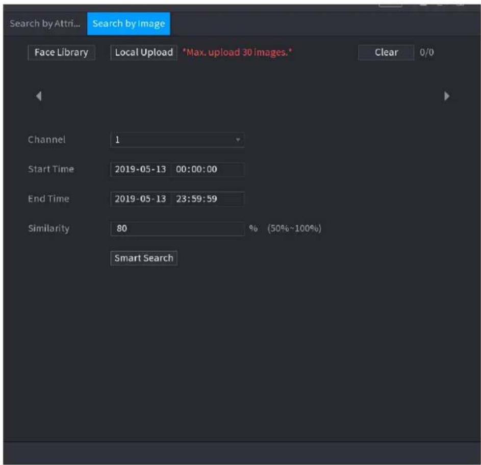
text_image
Search by Attni... Search by Image Face Library Local Upload *Max. upload 30 images.* Clear 0/0 Channel 1 Start Time 2019-05-13 00:00:00 End Time 2019-05-13 23:59:59 Similarity 80 % (50%~100%) Smart SearchStep 2 Select the channel and set the parameters such as start time, end time, gender, age, glasses, beard, mask, and similarity according to your requirement.
Step 3 Click Smart Search.
The search result is displayed. See Figure 4-110.

The human face in the image is pixelated. The actual image is clear.
Figure 4-110
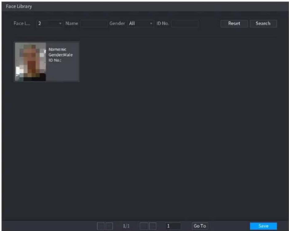
text_image
Face Library Face L: 2 Name Gender All ID No. Reset Search Nomencl Gender:Male ID No:Step 4 Click the picture that you want to play back.
The picture with registered information is displayed.
You can also do the following operations to the recorded files.
- To back up the recorded files to the external storage device, select files, click Backup, select the save path and file type, and then click Start.
- To lock the files to make it unable to be overwritten, select the files, and then click Lock.
• To add a mark to the file, select the files and then click Add Mark. - Go to the Face Properties and Person Details to view detailed information.
4.7.1.3 IVS
You can search and playback the alarm record files.
Step 1 Select Main Menu > AI > SMART SEARCH > IVS.
The IVS interface is displayed. See Figure 4-111.
Figure 4-111
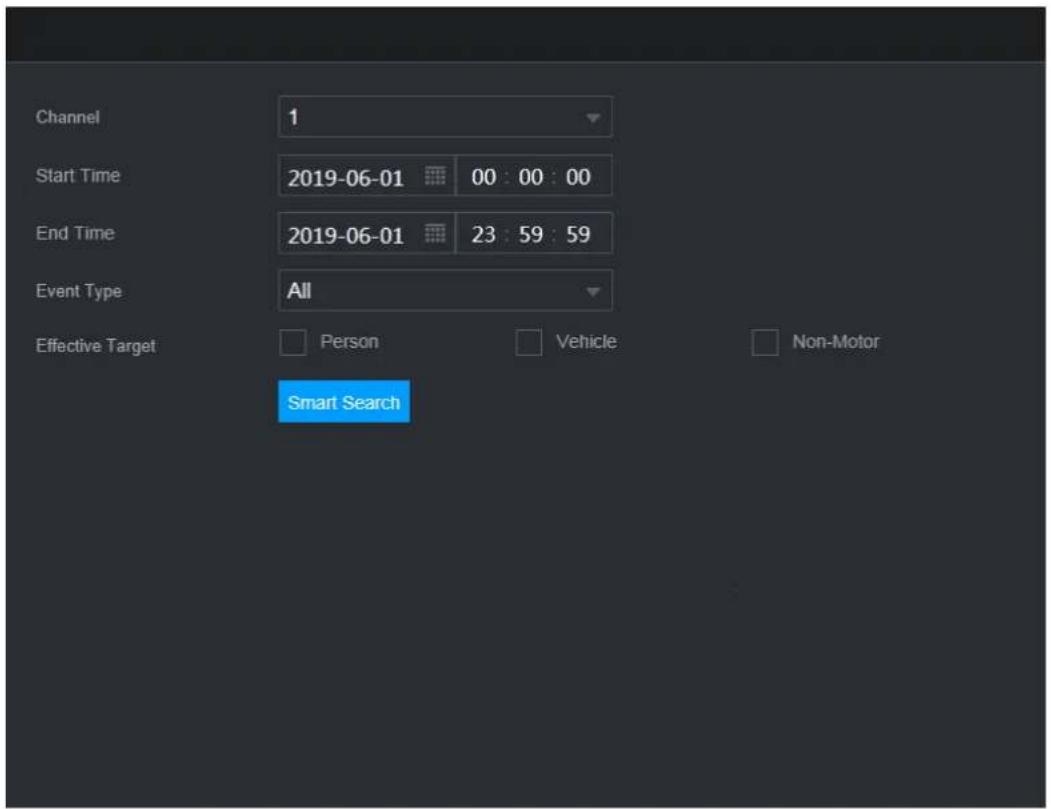
text_image
Channel 1 Start Time 2019-06-01 00:00:00 End Time 2019-06-01 23:59:59 Event Type All Effective Target Person Vehicle Non-Motor Smart SearchStep 2 Select a channel, start time, end time, event type, and then click Smart search, The search result is displayed.
Step 3 Click the picture that you want to play back.
You can also do the following operations to the recorded files.
- To back up the recorded files to the external storage device, select files, click Backup, select the save path and file type, and then click Start.
- To lock the files to make it unable to be overwritten, select the files, and then click Lock.
• To add a mark to the file, select the files and then click Add Mark. - Go to the Face Properties and Person Details to view detailed information.
4.7.1.4 Human Body Detection
You can search the human body and search the alarm record during the specified period.
Step 1 Select Main Menu > AI > SMART SEARCH > HUMAN BODY DETECTION.
The Human Body Detection interface is displayed. See Figure 4-112.
Figure 4-112
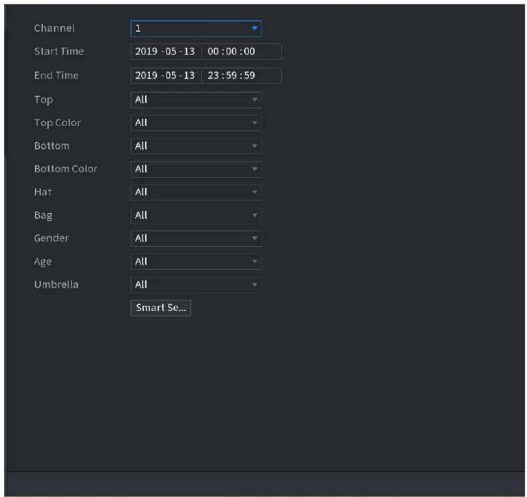
text_image
Channel 1 Start Time 2019 -05 -13 00 :00 :00 End Time 2019 -05 -13 23 :59 :59 Top All Top Color All Bottom All Bottom Color All Hat All Bag All Gender All Age All Umbrella All Smart Se...Step 2 Select a channel, start time, end time, and set corresponding parameters.
Step 3 Click Smart search.
The search result is displayed. See Figure 4-113.

For privacy reason, the human face in the image is pixelated.
Figure 4-113
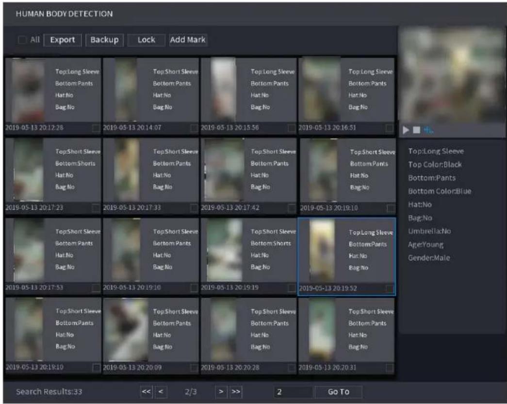
text_image
HUMAN BODY DETECTION All Export Backup Lock Add Mark Top:Long Sleeve Bottom:Pants Hat:No Bag:No 2019-05-13 20:12:28 2019-05-13 20:14:07 2019-05-13 20:15:56 2019-05-13 20:16:51 Top:Short Sleeve Bottom:Shorts Hat:No Bag:No 2019-05-13 20:17:23 2019-05-13 20:17:33 2019-05-13 20:17:42 2019-05-13 20:19:10 Top:Short Sleeve Bottom:Shorts Hat:No Bag:No 2019-05-13 20:17:53 2019-05-13 20:19:10 2019-05-13 20:19:19 Top:Short Sleeve Bottom:Shorts Hat:No Bag:No 2019-05-13 20:19:52 Top:Short Sleeve Bottom:Shorts Hat:No Bag:No 2019-05-13 20:20:31 Top:Long Sleeve Top Color:Black Bottom:Pants Bottom Color:Blue Hat:No Bag:No Umbrella:No Age:Young Gender:Male Search Results:33 << < 2/3 > >> 2 Go ToStep 4 Select one or multiple results, and then you can
- To back up the recorded files to the external storage device, select files, click Backup, select the save path and file type, and then click Start.
- To lock the files to make it unable to be overwritten, select the files, and then click Lock.
• To add a mark to the file, select the files and then click Add Mark. - Go to the Face Properties and Person Details to view detailed information.
4.7.1.5 Vehicle Detection
You can search according to the vehicle parameters and search the alarm record during the specified period.

This function is for some series products only.
Step 1 Select Main Menu > AI > SMART SEARCH > VEHICLE DETECTION.
The VEHICLE DETECTION interface is displayed. See Figure 4-114.
Figure 4-114
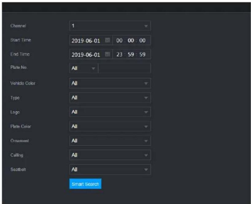
text_image
Channel 1 Start Time 2019-06-01 00:00:00 End Time 2019-06-01 23:59:59 Plate No. All Vehido Color All Type All Logo All Plate Color All Ornament All Calling All Seatbelt All Smart SearchStep 2 Select a channel and set parameters.

- System supports plate fuzzy search.
- System searches all plate numbers by default if you have not set a plate number.
Step 3 Click Smart search.
The search result is displayed.
Step 4 Select one or multiple results, and then you can:
- To back up the recorded files to the external storage device, select files, click Backup, select the save path and file type, and then click Start.
- To lock the files to make it unable to be overwritten, select the files, and then click Lock.
- To add a mark to the file, select the files and then click Add Mark.
4.7.1.6 Non-motor Vehicle Detection
You can search according to the non-motor vehicle parameters and search the alarm record during the specified period.

This function is for some series products only.
Step 1 Select Main Menu > AI > SMART SEARCH > NON-MOTOR VEHICLE DETECTION.
The NON-MOTOR VEHICLE DETECTION interface is displayed. See Figure 4-115.
Figure 4-115
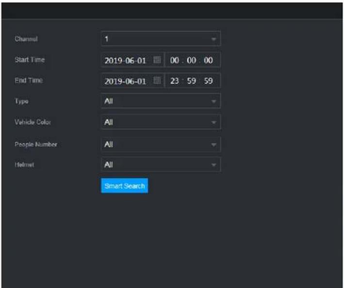
text_image
Channel 1 Start Time 2019-06-01 00:00 00 End Time 2019-06-01 23:59 59 Type All Vehicle Color All People Number All Helmet All Smart SearchStep 2 Select the channel and the time, and then select one or multiple features from Type, Vehicle Color, People Number, or Helmet.
Step 3 Click Smart Search. The search result is displayed. See Figure 4-116.
Figure 4-116
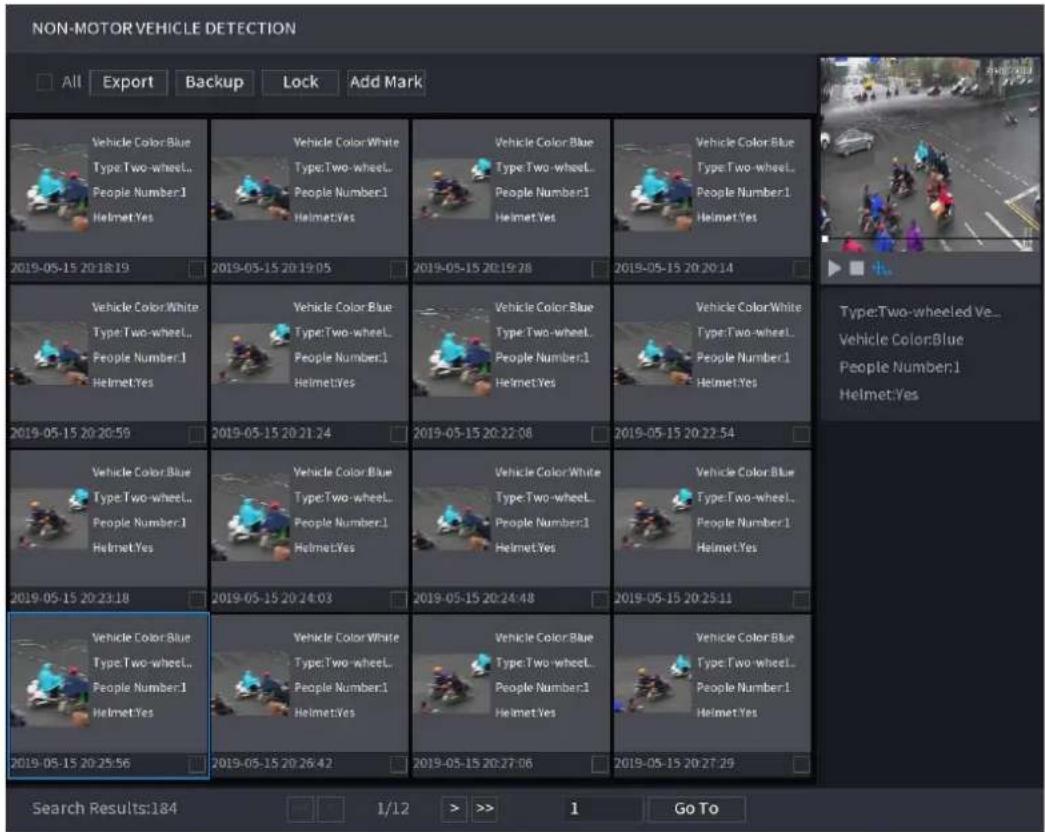
text_image
NON-MOTOR VEHICLE DETECTION All Export Backup Lock Add Mark Vehicle Color:Blue Type:Two-wheel... People Number:1 Helmet:Yes 2019-05-15 20:18:19 Vehicle Color:White Type:Two-wheel... People Number:1 Helmet:Yes 2019-05-15 20:19:05 Vehicle Color:Blue Type:Two-wheel... People Number:1 Helmet:Yes 2019-05-15 20:19:28 Vehicle Color:Blue Type:Two-wheel... People Number:1 Helmet:Yes 2019-05-15 20:20:14 Vehicle Color:White Type:Two-wheel... People Number:1 Helmet:Yes 2019-05-15 20:20:59 Vehicle Color:Blue Type:Two-wheel... People Number:1 Helmet:Yes 2019-05-15 20:21:24 Vehicle Color:Blue Type:Two-wheel... People Number:1 Helmet:Yes 2019-05-15 20:22:08 Vehicle Color:White Type:Two-wheel... People Number:1 Helmet:Yes 2019-05-15 20:22:54 Vehicle Color:Blue Type:Two-wheel... People Number:1 Helmet:Yes 2019-05-15 20:23:18 Vehicle Color:Blue Type:Two-wheel... People Number:1 Helmet:Yes 2019-05-15 20:24:03 Vehicle Color:White Type:Two-wheel... People Number:1 Helmet:Yes 2019-05-15 20:24:48 Vehicle Color:Blue Type:Two-wheel... People Number:1 Helmet:Yes 2019-05-15 20:25:11 Vehicle Color:Blue Type:Two-wheel... People Number:1 Helmet:Yes 2019-05-15 20:25:56 Vehicle Color:White Type:Two-wheel... People Number:1 Helmet:Yes 2019-05-15 20:26:42 Vehicle Color:Blue Type:Two-wheel... People Number:1 Helmet:Yes 2019-05-15 20:27:06 Vehicle Color Blue Type:Two-wheel... People Number:1 Helmet:Yes 2019-05-15 20:27:29 Search Results:184 1/12 > >> 1 Go ToStep 4 Select one or multiple results, and then you can
- To back up the recorded files to the external storage device, select files, click Backup, select the save path and file type, and then click Start.
- To lock the files to make it unable to be overwritten, select the files, and then click Lock.
• To add a mark to the file, select the files and then click Add Mark.
4.7.1.7 People Counting
You can detect the people amount in the specified zone, and display the statistics image.
Step 1 Select Main Menu > AI > SMART SEARCH > PEOPLE COUNTING. The PEOPLE COUNTING interface is displayed. See Figure 4-117.
Figure 4-117
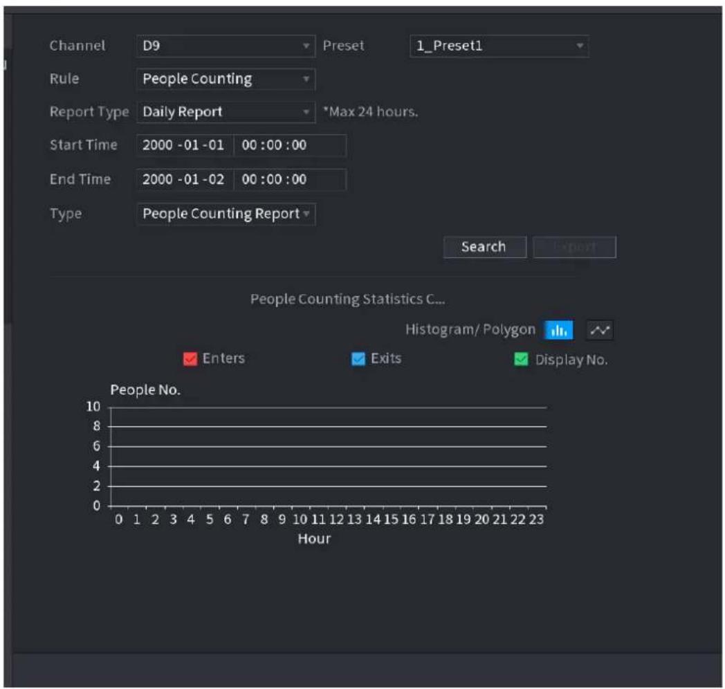
text_image
Channel D9 Preset 1_Preset1 Rule People Counting Report Type Daily Report *Max 24 hours. Start Time 2000 -01 -01 00 :00 :00 End Time 2000 -01 -02 00 :00 :00 Type People Counting Report Search Export People Counting Statistics C... Histogram/ Polygon Enters Exits Display No. People No. 10 8 6 4 2 0 HourStep 2 Set parameters such as channel, report type, start time, end time, etc. See Table 4-25.
Table 4-25
| Parameter | Description |
| Channel | Select the channel you want to search people amount. |
| Rule | Select the rule from the dropdown list. |
| Report Type | Select report type from the dropdown list: daily report, monthly report, yearly report. |
| Start time/end time | Set search start time and end time. |
| Type | Select from the dropdown list. |
4.7.1.8 Heat map
You can detect the active objects distribution in the monitor zone during the specified period, and use different colors to display on the heat map report.
4.7.1.8.1 Normal
Step 1 Select Main Menu > AI > SMART SEARCH > HEAT MAP > NORMAL.
The Normal interface is displayed. See Figure 4-118.
Figure 4-118
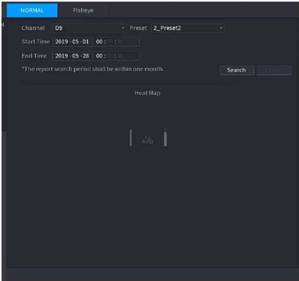
text_image
NORMAL Fisheye Channel D9 Preset 2_Preset2 Start Time 2019 -05 -01 00 : 00 : 00 End Time 2019 -05 -28 00 : 00 : 00 *The report search period shall be within one month. Search Export Heat MapStep 2 Select channel, start time, end time.
Step 3 Click Search.
Step 4 System display heat map report.

Click Export, and then select path. Click Save to save current report to the USB device.
4.7.1.8.2 Fisheye
Step 1 Select Main Menu > AI > SMART SEARCH > HEAT MAP > Fisheye.
The Fisheye interface is displayed. See Figure 4-119.
Figure 4-119
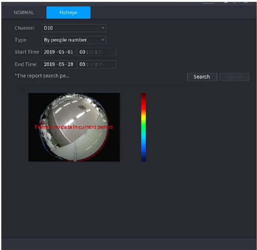
text_image
NORMAL Fisheye Channel D10 Type By people number Start Time 2019 -05 -01 00 : 00 : 00 End Time 2019 -05 -28 00 : 00 : 00 *The report search pe... Search Export There is no data in current period.Step 2 Set Channel, Type, Start Time, End time.
Step 3 Click Search.
Step 4 System displays heat map report.

Click Export and then select saved path, click Save to save the heat map report to the USB device.
4.7.2 Parameters
4.7.2.1 Smart Plan
The smart plan is for the smart network camera. It includes IVS, human face detection, human face recognition, human body detection, people counting, heat map. If you do not set a rule here, you cannot use these AI intelligent functions when you are connecting to a smart network camera.
This series NVR products support AI by camera only. Make sure the connected network camera supports intelligent functions. For NVR, it just displays the intelligent alarm information from the smart network camera and set or playback the record file.
Step 1 Select Main menu > AI > PARAMETERS > SMART PLAN.
The SMART PLAN interface is displayed. See Figure 4-120.
Figure 4-120
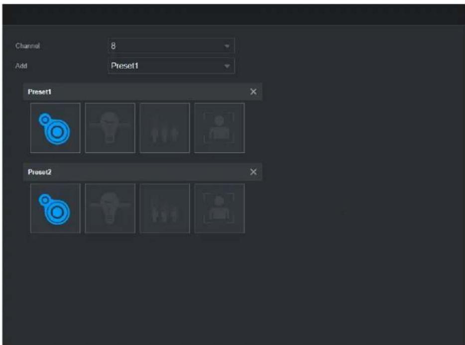
text_image
Channel 8 Add Preset1 Preset1 Preset2Step 2 Select a channel number.
System displays different smart plan interfaces since the remote device may supports different functions.
- The interface is shown as Figure 4-121 if the remote device supports preset function.
Figure 4-121
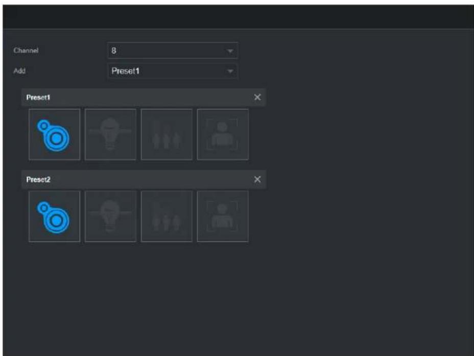
text_image
Channel 8 Add Preset1 Preset1 Preset21) Select a channel.
2) Select a preset.
3) Click the smart plan icon at the bottom left. The icon becomes highlighted.
4) Click Apply.


elete the preset.
- Click Add to add a preset.
- Once the remote device does not support preset function, the interface is shown as in Figure 4-122.
Figure 4-122
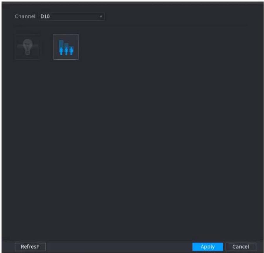
text_image
Channel D10 Refresh Apply Cancel1) Select a channel.
2) Click the smart plan icon. The icon becomes blue highlighted.
3) Click Apply.
4.7.2.2 Face Detection
The Device can analyze the pictures captured by the camera to detect whether the faces are on the pictures. You can search and filter the recorded videos the faces and play back.
Preparations
The connected camera shall support human face detection function.
Step 1 Select Main Menu > AI > PARAMETERS > FACE DETECTION. The FACE DETECTION interface is displayed. See Figure 4-123.
Figure 4-123
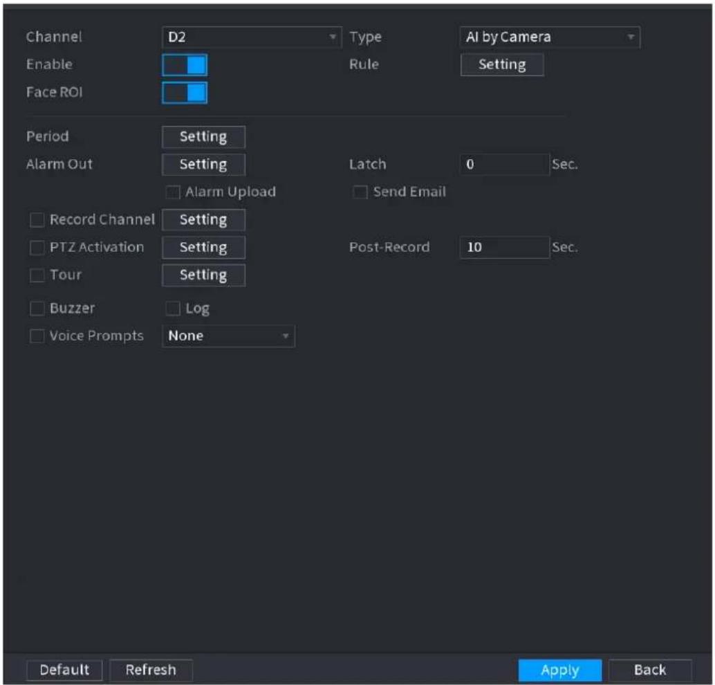
text_image
Channel Enable Face ROI D2 Type Rule AI by Camera Setting Period Setting Alarm Out Setting Latch 0 Sec. Alarm Upload Send Email Record Channel Setting PTZ Activation Setting Post-Record 10 Sec. Tour Setting Buzzer Log Voice Prompts None Default Refresh Apply BackStep 2 In the Channel list, select a channel that you want to configure face detection function, and then enable it.
Step 3 Configure the parameters. See Table 4-26.
Table 4-26
| Parameter | Description |
| Type | This series NVR products support AI by Camera only. AI by Camera means the connected camera does all the AI analytics, and then gives the results to the NVR. |
| Face Rol | Check the box to enable Face Rol function, system displays human face at the enhanced way. |
| Rule | Click Setting to draw areas to filter the target.You can configure two filtering targets (maximum size and minimum size). When the target is smaller than the minimum size or larger than the maximum size, no alarms will be activated. The maximum size should be larger than the minimum size. Left click to drag the four angles to adjust the size. |
| Period | Configure the period and in the set time range, the corresponding configuration item will be linked to start the alarm. |
| Alarm Out | The alarm device (such as lights, sirens, etc.) is connected to the alarm output port. When an alarm occurs, the NVR device transmits the alarm information to the alarm device. |
| Latch | When the alarm ends, the alarm extended for a period of time. The time range is from 0 seconds to 300 seconds. |
| Alarm Upload | Select the check box. When an alarm occurs, the NVR device uploads an alarm signal to the network (including the alarm center).This function is for some series products only.You need to set the alarm center first. For details, see "4.12.9 Alarm Centre." |
| Send Email | Select the check box. When an alarm occurs, the NVR device sends an email to the set mailbox to notify the user.You need to set the email first. For details, see "4.12.6 Email." |
| Record Channel | Select the check box and select the needed recording channel (support multiple choices). When an alarm occurs, the NVR device activates the channel fo recording.You need to enable intelligent recording and auto recording first. For details, see "4.1.4.6 Schedule." |
| PTZ Activation | Select the check box and clickSettingto select the channel and PTZ action. When an alarm occurs, the NVR device associates the channel to perform the corresponding PTZ action. For example, activate the PTZ in channel one to turn to the preset point X.Tripwire alarm supports to activate PTZ preset point only.You need to set the corresponding PTZ actions first, see "4.4.3 Configuring PTZ Functions." |
| Delay | At the end of the alarm, the recording extends for a period of time. The time range is from 10 seconds to 300 seconds. |
| Tour | Select the check box and select the channel for tour. When an alarm occurs, the local interface of the NVR device displays the selected channel screen.You need to set the time interval and mode for tour first, see "4.16.2 Tour."After the tour is over, the preview interface is restored to the screen split mode before the tour. |
| Log | Select the check box, the NVR device records the alarm information in the log when an alarm occurs. |
| VoicePrompts | Check the box and then select the corresponding audio file from the dropdown list. System plays the audio file when the alarm occurs.[IMAGE]Refer to "4.17.1 File Manage" to add audio file first. |
| Buzzer | Select the check box to activate the buzzer when an alarm occurs. |
Step 4 Click Apply to complete the settings.
4.7.2.3 Face Recognition
You can compare the detected faces with the faces in the library to judge if the detected face belongs to the library. The comparison result will be displayed on the AI mode live view screen and smart search interface, and link the alarms.
This series NVR products support AI by camera only.
You can use the connected camera to realize AI function. Make sure the connected camera supports human face detection function.
Step 1 Select Main Menu > AI > PARAMETERS > FACE RECOGNITION. The FACE RECOGNITION interface is displayed. See Figure 4-124.
Figure 4-124
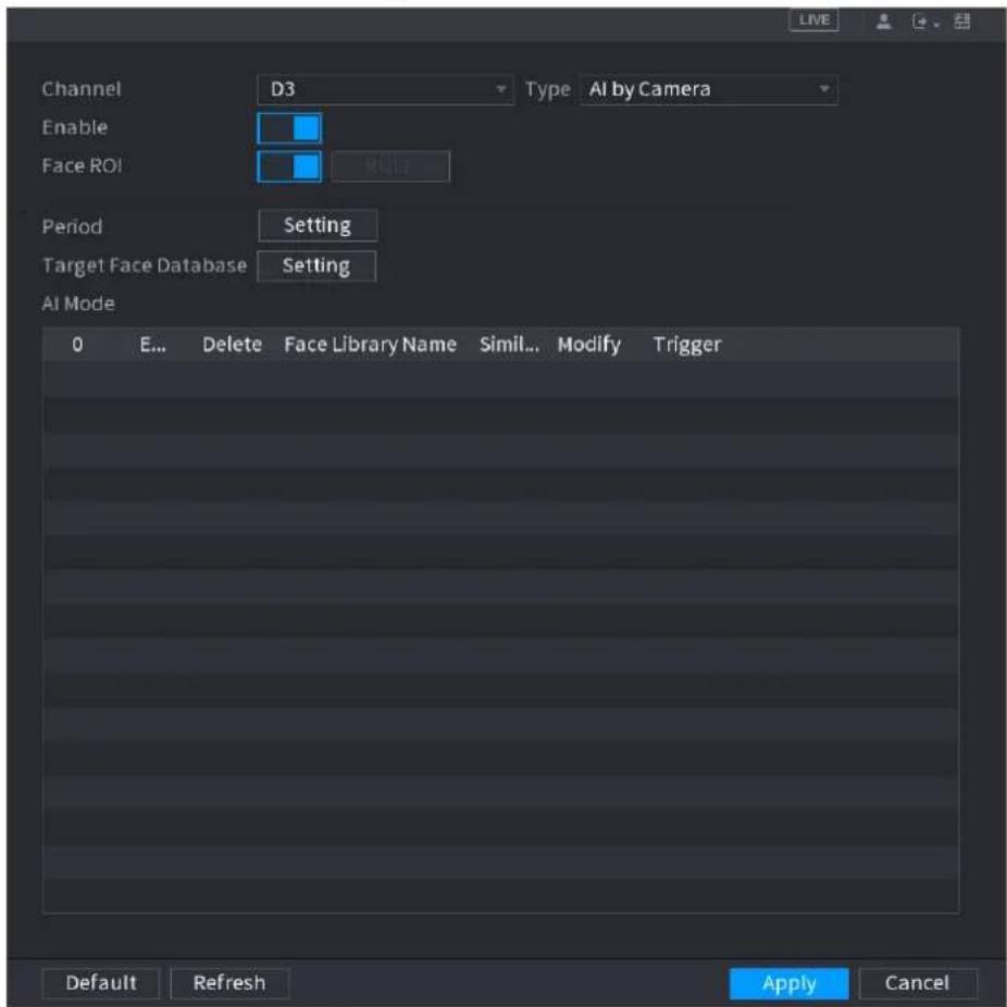
text_image
Channel Enable Face ROI Period Target Face Database AI Mode 0 E... Delete Face Library Name Simil... Modify Trigger Default Refresh Apply Cancel Type AI by CameraStep 2 In the Channel list, select a channel that you want to configure face recognition function, and then enable it.
Step 3 At Type, system supports AI by Camera only.
Step 4 Set parameters. See Table 4-27.
Table 4-27
| Parameter | Description |
| Rol | Check the box to enable Rol function, system displays human face at the enhanced way. |
| Rule | Click Setting to draw areas to filter the target.You can configure two filtering targets (maximum size and minimum size).When the target is smaller than the minimum size or larger than the maximum size, no alarms will be activated. The maximum size should be larger than the minimum size. Left click to drag the four angles to adjust the size. |
| Period | Configure the period and in the set time range, the corresponding configuration item will be linked to start the alarm. |
| Target Face Database | Click Target Face Database, system displays face database list. Select a database from the dropdown list to compare. |
Step 5 Set the Target Face Database.
Step 6 (Optional)Click 📋 to modify the similarity. The lower the number is, the easier the alarm linkage will trigger.
Step 7 Click to set the alarm linkage. See Figure 4-125.

Refer to "4.7.3 Database" for human target database settings information.
Figure 4-125
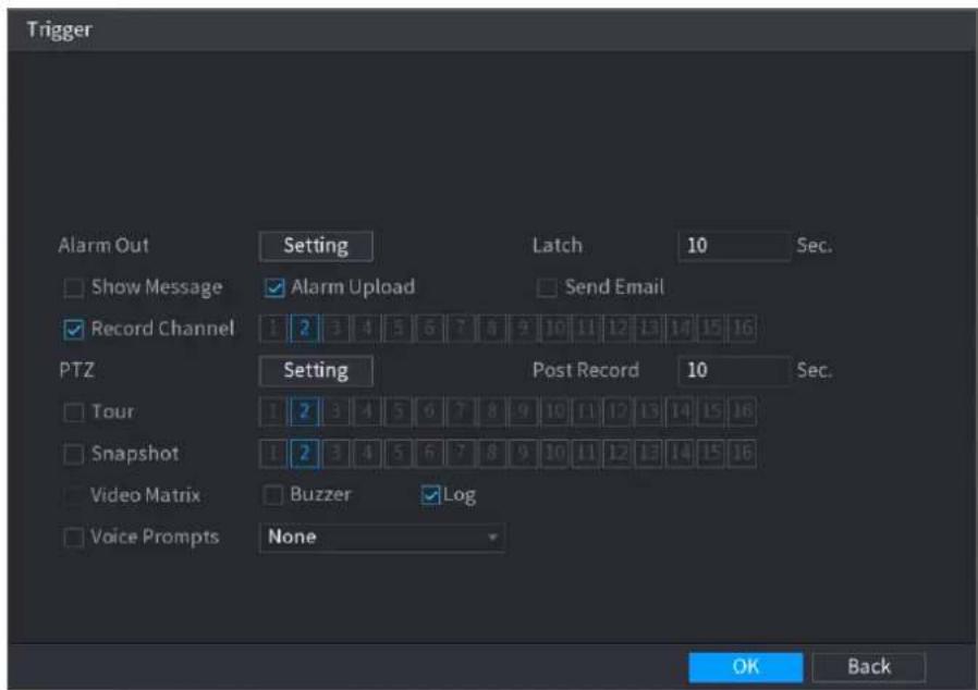
text_image
Trigger Alarm Out Setting Latch 10 Sec. Show Message Alarm Upload Send Email Record Channel 1 2 3 4 5 6 7 8 9 10 11 12 13 14 15 16 PTZ Setting Post Record 10 Sec. Tour 1 2 3 4 5 6 7 8 9 10 11 12 13 14 15 16 Snapshot 1 2 3 4 5 6 7 8 9 10 11 12 13 14 15 16 Video Matrix Buzzer Log Voice Prompts None OK BackStep 8 Configure the parameters. See Table 4-28.
Table 4-28
| Parameter | Description |
| Period | Configure the period and in the set time range, the corresponding configuration item will be linked to start the alarm. |
| Alarm Out | The alarm device (such as lights, sirens, etc.) is connected to the alarm output port. When an alarm occurs, the NVR device transmits the alarm information to the alarm device. |
| Latch | When the alarm ends, the alarm extended for a period of time. The time range is from 0 seconds to 300 seconds. |
| Alarm Upload | Select the check box. When an alarm occurs, the NVR device uploads an alarm signal to the network (including the alarm center).This function is for some series products only.You need tol set the alarm center first. For details, see "4.12.9 Alarm Centre." |
| Send Email | Select the check box. When an alarm occurs, the NVR device sends an email to the set mailbox to notify the user.You need to set the email first. For details, see "4.12.6 Email." |
| Record Channel | Select the check box and select the needed recording channel (support multiple choices). When an alarm occurs, the NVR device activates the channel fo recording.You need to enable intelligent recording and auto recording first. For details, see "4.1.4.6 Schedule." |
| PTZ Activation | Select the check box and clickSettingto select the channel and PTZ action. When an alarm occurs, the NVR device associates the channel to perform the corresponding PTZ action. For example, activate the PTZ in channel one to turn to the preset point X.Tripwire alarm supports to activate PTZ preset point only.You need to set the corresponding PTZ actions first, see "4.4.3 Configuring PTZ Functions." |
| Delay | At the end of the alarm, the recording extends for a period of time. The time range is from 10 seconds to 300 seconds. |
| Tour | Select the check box and select the channel for tour. When an alarm occurs, the local interface of the NVR device displays the selected channel screen.You need to set the time interval and mode for tour first, see "4.16.2 Tour."After the tour is over, the preview interface is restored to the screen split mode before the tour. |
| Log | Select the check box, the NVR device records the alarm information in the log when an alarm occurs. |
| VoicePrompts | Check the box and then select the corresponding audio file from the dropdown list. System plays the audio file when the alarm occurs.[IMAGE]Refer to "4.17.1 File Manage" to add audio file first. |
| Buzzer | Select the check box to activate the buzzer when an alarm occurs. |
Step 9 Click OK, system goes back to human face recognition interface.
Step 10 Click Apply to complete the settings.
The interface is shown as Figure 4-126 if there is matched result.
Figure 4-126
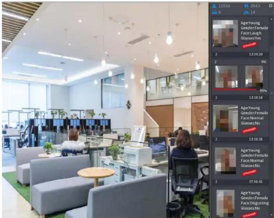
text_image
Photo of a modern office interior with employees at desks and overlaid facial recognition bounding boxes showing age, gender, and facial expressions.4.7.2.4 IVS (General Behavior Analytics)
The IVS function processes and analyzes the images to extract the key information to match with the specified rules. When the detected behaviors match with the rules, the system activates alarms.

● This function is for some series product only.
- IVS function and human face detection function cannot be valid at the same time.
The IVS function environment shall meet the following requirements:
● The object total size shall not be more than 10% of the whole video.
- The object size on the video shall not be more than 10pixels*10 pixels. The abandoned object size shall be more than 15pixels*15 pixels (CIF resolution). The object width shall not be more than 1/3 of the video height and width. The recommended height is 10% of the video.
● The object and the background brightness different shall be more than 10 grey levels.
- The object shall remain on the video for more than 2 seconds. The moving distance is larger than its own width and shall not be smaller than 15 pixels (CIF resolution).
- The surveillance environment shall not be too complicated. The IVS function is not suitable for the environment of too many objects or the changing light. - The surveillance environment shall not contain glasses, reflection light from the ground, and water. Free of tree branches, shadow, mosquito and bugs. Do not use the IVS function in the backlight environment, avoid direct sunlight.
Step 1 Select Main Menu > AI > PARAMETERS > IVS.
The IVS interface is displayed. See Figure 4-127.
Figure 4-127
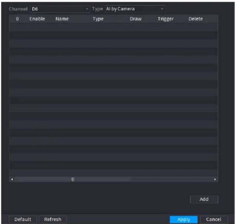
text_image
Channel D6 Type AI by Camera 0 Enable Name Type Draw Trigger Delete Add Default Refresh Apply CancelStep 2 Select a channel from the dropdown list.
Click Add and then set corresponding rule. See Figure 4-128.

Click to delete the selected rule.
Figure 4-128
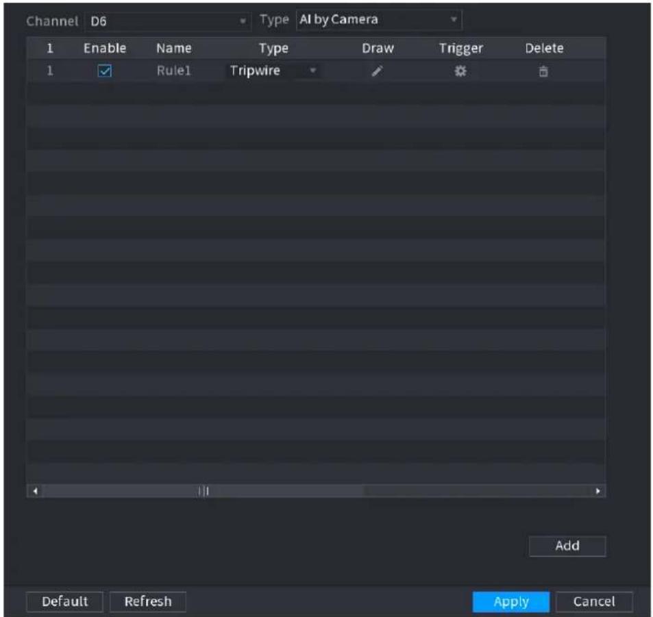
text_image
Channel D6 Type AI by Camera 1 Enable Name Type Draw Trigger Delete 1 Rule1 Tripwire Add Default Refresh Apply CancelStep 3 Set corresponding parameters.
Step 4 Click Apply.
4.7.2.4.1 Tripwire
When the detection target crosses the warning line along the set direction, the system performs an alarm linkage action.
Step 1 Select Main Menu > AI > PARAMETERS > IVS.
In the Type drop-down list, select Tripwire. See Figure 4-129.
Figure 4-129
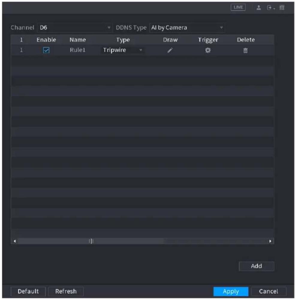
text_image
Channel D6 DDNS Type AI by Camera 1 Enable Name Type Draw Trigger Delete 1 ✓ Rule1 Tripwire ✓ Add Default Refresh Apply CancelStep 2 Draw the detection rule.
1) Click 📋 to draw the rule on the surveillance video, the system displays as Figure 4-130.
Figure 4-130
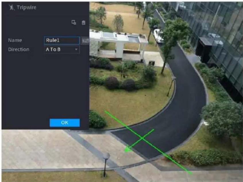
text_image
Tripwire Name Rule1 Direction A To B OK2) Configure the parameters. See Table 4-29.
Table 4-29
| Parameter | Description |
| Name | Customize the rule name. |
| Direction | Set the tripwire direction, including A→B, B→A and A↔B. |
| Filter target | Click  ilter the target. Check the blue wireframe and adjust the size of the area with the mouse. ilter the target. Check the blue wireframe and adjust the size of the area with the mouse. Each rule can set 2 target filters (maximum size and minimum size), that is, when the passing target is smaller than the minimum target or larger than the maximum target, no alarm will be generated. The maximum size should not be smaller than the minimum size. Each rule can set 2 target filters (maximum size and minimum size), that is, when the passing target is smaller than the minimum target or larger than the maximum target, no alarm will be generated. The maximum size should not be smaller than the minimum size. |
| AI Recognition | Select AI recognition and the system displays alarm target. The default selection is person and motor vehicle and system automatically identifies the person and motor vehicle appeared within the monitoring range. When you select IVS of AI by camera, the connected channel shall support tripwire function. When you select IVS of AI by camera, the connected channel shall support tripwire function. |
1) Press and hold down the left button on the monitor screen to draw the line. The line can be a straight line or a curve.
2) Click OK to complete the rule setting.
Step 3 Click

System displays the Trigger interface. See Figure 4-131.
Figure 4-131
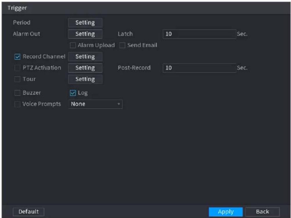
text_image
Trigger Period Setting Alarm Out Setting Latch 10 Sec. □ Alarm Upload □ Send Email ✓ Record Channel Setting □ PTZ Activation Setting Post-Record 10 Sec. □ Tour Setting □ Buzzer ✓ Log □ Voice Prompts None Default Apply BackStep 4 Configure the parameters. See Table 4-30.
Step 5 Click OK to save the alarm setting.
System displays the IVS interface.
Table 4-30
Step 6 Select the Enable check box and click Apply to complete the tripwire setting.
| Parameter | Description |
| Period | Configure the period and in the set time range, the corresponding configuration item will be linked to start the alarm. |
| Alarm Out | The alarm device (such as lights, sirens, etc.) is connected to the alarm output port. When an alarm occurs, the NVR device transmits the alarm information to the alarm device. |
| Latch | When the alarm ends, the alarm extended for a period of time. The time range is from 0 seconds to 300 seconds. |
| Alarm Upload | Select the check box. When an alarm occurs, the NVR device uploads an alarm signal to the network (including the alarm center).This function is for some series products only.You need to set the alarm center first. For details, see "4.12.9 Alarm Centre." |
| Send Email | Select the check box. When an alarm occurs, the NVR device sends an email to the set mailbox to notify the user.You need to set the email first. For details, see "4.12.6 Email." |
| Record Channel | Select the check box and select the needed recording channel (support multiple choices). When an alarm occurs, the NVR device activates the channel for recording. You need to enable intelligent recording and auto recording first. For details, see "4.1.4.6 Schedule." You need to enable intelligent recording and auto recording first. For details, see "4.1.4.6 Schedule." |
| PTZ Activation | Select the check box and click Setting to select the channel and PTZ action. When an alarm occurs, the NVR device associates the channel to perform the corresponding PTZ action. For example, activate the PTZ in channel one to turn to the preset point X. Tripwire alarm supports to activate PTZ preset point only.You need to set the corresponding PTZ actions first, see "4.4.3 Configuring PTZ Functions." Tripwire alarm supports to activate PTZ preset point only.You need to set the corresponding PTZ actions first, see "4.4.3 Configuring PTZ Functions." |
| Delay | At the end of the alarm, the recording extends for a period of time. The time range is from 10 seconds to 300 seconds. |
| Tour | Select the check box and select the channel for tour. When an alarm occurs, the local interface of the NVR device displays the selected channel screen. You need to set the time interval and mode for tour first, see "4.16.2 Tour."After the tour is over, the preview interface is restored to the screen split mode before the tour. You need to set the time interval and mode for tour first, see "4.16.2 Tour."After the tour is over, the preview interface is restored to the screen split mode before the tour. |
| Log | Select the check box, the NVR device records the alarm information in the log when an alarm occurs. |
| Voice Prompts | Check the box and then select the corresponding audio file from the dropdown list. System plays the audio file when the alarm occurs. Refer to "4.17.1 File Manage" to add audio file first. Refer to "4.17.1 File Manage" to add audio file first. |
| Buzzer | Select the check box to activate the buzzer when an alarm occurs. |
4.7.2.4.2 Intrusion
When the detection target passes the edge of the monitoring area, and enters, leaves or traverses the monitoring area, the system performs an alarm linkage action.
Step 1 In the Type drop-down list, select Intrusion. See Figure 4-132.
Figure 4-132
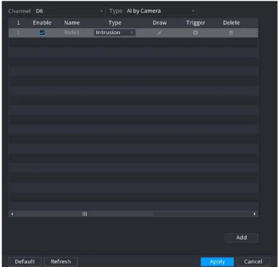
text_image
Channel D6 Type AI by Camera 1 Enable Name Type Draw Trigger Delete 1 Rule1 Intrusion Add Default Refresh Apply CancelStep 2 Draw the detection rule.
1) Click to draw the rule on the surveillance video, the system displays as
2) Figure 4-133.
Figure 4-133
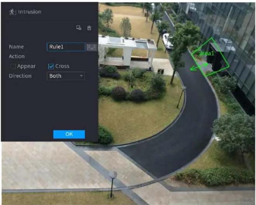
text_image
Intrusion Name Rule1 Action Appear Cross Direction Both OK area13) Configure the parameters. See Table 4-31.
Table 4-31
| Parameter | Description |
| Name | Customize the rule name. |
| Action | Set the intrusion action, including appear and crossing area. |
| Direction | Set the direction to cross the area, including enter, exit and both. |
| Filter target | Click  ilter the target. Check the blue wireframe and adjust the size of the area with the mouse.[IMAGE]Each rule can set 2 target filters (maximum size and minimum size), that is, when the passing target is smaller than the minimum target or larger than the maximum target, no alarm will be generated. The maximum size should not be smaller than the minimum size. ilter the target. Check the blue wireframe and adjust the size of the area with the mouse.[IMAGE]Each rule can set 2 target filters (maximum size and minimum size), that is, when the passing target is smaller than the minimum target or larger than the maximum target, no alarm will be generated. The maximum size should not be smaller than the minimum size. |
| AI recognition | Select AI recognition and the system displays alarm target. The default selection is person and motor vehicle and system automatically identifies the person and motor vehicle appeared within the monitoring range. |
4) Press and hold down the left button on the monitoring screen to draw the monitoring area.
5) Click OK to complete the rule setting.

Step 3 Click 📄, you can refer to the "4.7.2.4.1 Tripwire" to set other parameters.
Step 4 Select the Enable check box and click Apply to complete the intrusion setting.
4.7.2.4.3 Abandoned Object Detection
System generates an alarm when there is abandoned object in the specified zone.
Step 1 In the Type drop-down list, select Abandoned Object.
The interface is shown as Figure 4-134.
Figure 4-134
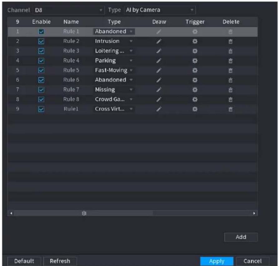
text_image
Channel D8 Type AI by Camera 9 Enable Name Type Draw Trigger Delete 1 ✓ Rule 1 Abandoned ✓ ❄ ❄ ❄ 2 ✓ Rule 2 Intrusion ✓ ❄ ❄ ❄ 3 ✓ Rule 3 Loitering ... ✓ ❄ ❄ ❄ 4 ✓ Rule 4 Parking ✓ ❄ ❄ ❄ 5 ✓ Rule 5 Fast-Moving ✓ ❄ ❄ ❄ 6 ✓ Rule 6 Abandoned ✓ ❄ ❄ ❄ 7 ✓ Rule 7 Missing ✓ ❄ ❄ ❄ 8 ✓ Rule 8 Crowd Ga... ✓ ❄ ❄ ❄ 9 ✓ Rule 1 Cross Virt... ✓ ❄ ❄ ❄ Add Default Refresh Apply CancelStep 2 Draw the detection rule.
1) Click to draw the rule on the surveillance video. See Figure 4-135.
Figure 4-135
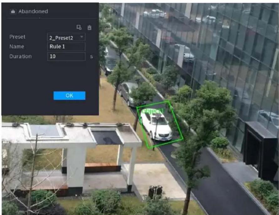
text_image
Abandoned Preset 2_Preset2 Name Rule 1 Duration 10 5 OK2) Set parameters. See Table 4-32.
Table 4-32
| Parameter | Description |
| Preset | Select a preset you want to use IVS |
| Name | Input customized rule name |
| Duration | System can generate an alarm once the object is in the zone for the specified period. |
| Filter target | Click  ilter the target. Check the blue wireframe and adjust the size of the area with the mouse.Each rule can set 2 target filters (maximum size and minimum size), that is, when the passing target is smaller than the minimum target or larger than the maximum target, no alarm will be generated. The maximum size should not be smaller than the minimum size. ilter the target. Check the blue wireframe and adjust the size of the area with the mouse.Each rule can set 2 target filters (maximum size and minimum size), that is, when the passing target is smaller than the minimum target or larger than the maximum target, no alarm will be generated. The maximum size should not be smaller than the minimum size. |
3) Draw a rule. Left click mouse to draw a zone, until you draw a rectangle, you can right click mouse.
4) Click OK to complete the rule setting.

Step 3 Click, you can refer to the "4.7.2.4.1 Tripwire" to set other parameters.
Step 4 Click Apply to complete the setup.
4.7.2.4.4 Fast moving
You can detect the fast moving object in the specified zone.
Step 1 In the Type drop-down list, select Fast Moving.
The interface is shown as below. See Figure 4-136.
Figure 4-136
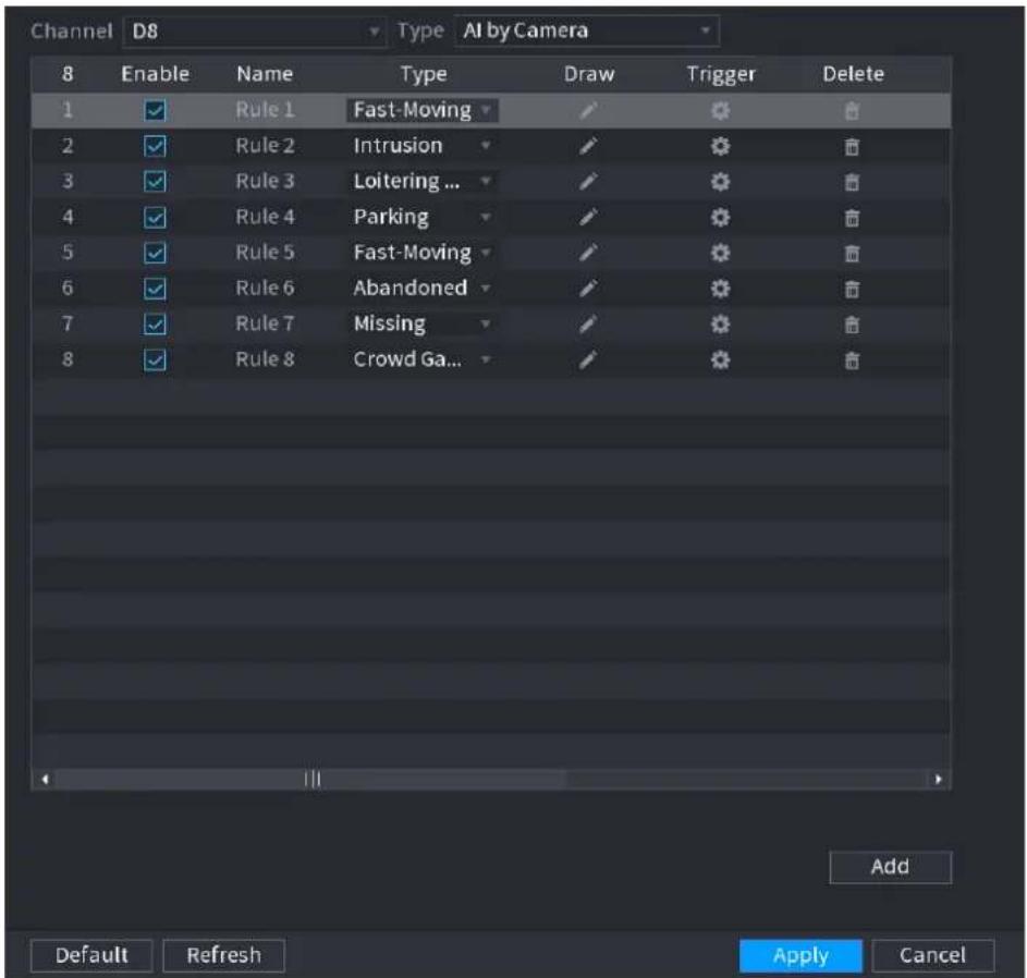
text_image
Channel D8 Type AI by Camera 8 Enable Name Type Draw Trigger Delete 1 ✓ Rule 1 Fast-Moving ✓ 2 ✓ Rule 2 Intrusion ✓ 3 ✓ Rule 3 Loitering ... ✓ 4 ✓ Rule 4 Parking ✓ 5 ✓ Rule 5 Fast-Moving ✓ 6 ✓ Rule 6 Abandoned ✓ 7 ✓ Rule 7 Missing ✓ 8 ✓ Rule 8 Crowd Ga... ✓ Add Default Refresh Apply CancelStep 2 Draw the detection rule.
1) Click to draw the rule on the surveillance video. See Figure 4-137.
Figure 4-137
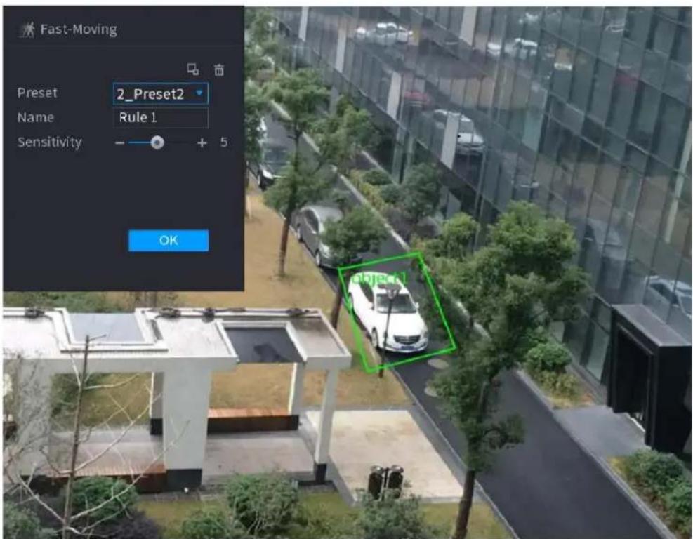
text_image
Fast-Moving Preset 2_Preset2 Name Rule 1 Sensitivity - + 5 OK object2) Set parameters. See Table 4-33.
Table 4-33
| Parameter | Description |
| Preset | Select a preset you want to use IVS |
| Name | Input customized rule name |
| Sensitivity | You can set alarm sensitivity. The value ranges from 1 to 10.The default setup is 5. |
| Filter target | Click  filter the target. Check the blue wireframe and adjust the size of the area with the mouse.[IMAGE]Each rule can set 2 target filters (maximum size and minimum size), that is, when the passing target is smaller than the minimum target or larger than the maximum target, no alarm will be generated. The maximum size should not be smaller than the minimum size. filter the target. Check the blue wireframe and adjust the size of the area with the mouse.[IMAGE]Each rule can set 2 target filters (maximum size and minimum size), that is, when the passing target is smaller than the minimum target or larger than the maximum target, no alarm will be generated. The maximum size should not be smaller than the minimum size. |
3) Draw a rule. Left click mouse to draw a zone, until you draw a rectangle, you can right click mouse.
4) Click OK to complete the rule setting.
Step 3 Click, you can refer to the "4.7.2.4.1 Tripwire" to set other parameters.
Step 4 Click Apply to complete the setup.
4.7.2.4.5 Crowd Gathering
System can generate an alarm once the people amount gathering in the specified zone is larger than the threshold.
Step 1 In the Type drop-down list, select Crowd Gathering Estimation. The interface is shown as below. See Figure 4-138.
Figure 4-138
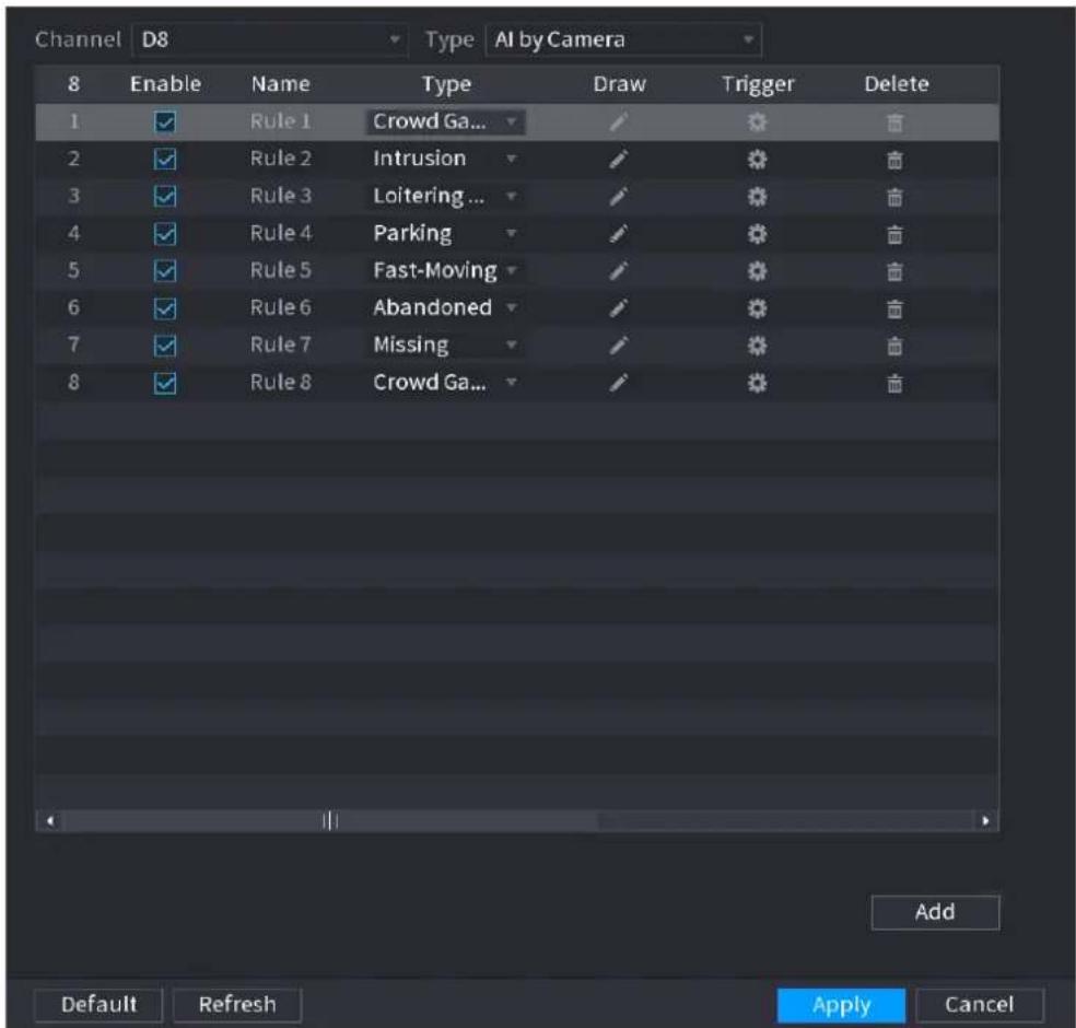
text_image
Channel D8 Type AI by Camera 8 Enable Name Type Draw Trigger Delete 1 ✓ Rule 1 Crowd Ga... ✓ ❄ ❄ 2 ✓ Rule 2 Intrusion ✓ ❄ ❄ ❄ 3 ✓ Rule 3 Loitering ... ✓ ❄ ❄ ❄ 4 ✓ Rule 4 Parking ✓ ❄ ❄ ❄ 5 ✓ Rule 5 Fast-Moving ✓ ❄ ❄ ❄ 6 ✓ Rule 6 Abandoned ✓ ❄ ❄ ❄ 7 ✓ Rule 7 Missing ✓ ❄ ❄ ❄ 8 ✓ Rule 8 Crowd Ga... ✓ ❄ ❄ ❄ Add Default Refresh Apply CancelStep 2 Draw the detection rule.
1) Click to draw the rule on the surveillance video. See Figure 4-139.
Figure 4-139
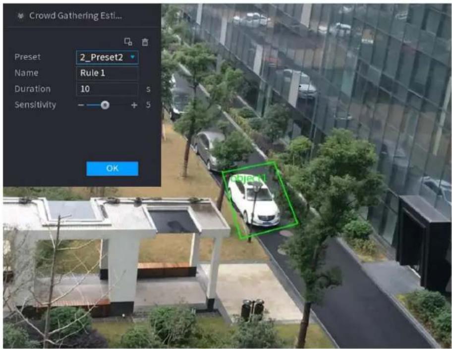
text_image
Crowd Gathering Esti... Preset 2_Preset2 Name Rule 1 Duration 10 S Sensitivity - + 5 OK2) Set parameters. See Table 4-34.
Table 4-34
| Parameter | Description |
| Preset | Select a preset you want to use IVS. |
| Name | Input customized rule name |
| Duration | Set the minimum time that the object stays until the alarm is triggered. |
| Filter target | Click  ilter the target. Check the blue wireframe and adjust the size of the area with the mouse.Each rule can set 2 target filters (maximum size and minimum size), that is, when the passing target is smaller than the minimum target or larger than the maximum target, no alarm will be generated. The maximum size should not be smaller than the minimum size. ilter the target. Check the blue wireframe and adjust the size of the area with the mouse.Each rule can set 2 target filters (maximum size and minimum size), that is, when the passing target is smaller than the minimum target or larger than the maximum target, no alarm will be generated. The maximum size should not be smaller than the minimum size. |
3) Draw a rule. Left click mouse to draw a zone, until you draw a rectangle, you can right click mouse.
4) Click OK to complete the rule setting.
Step 3 Click, you can refer to the "4.7.2.4.1 Tripwire" to set other parameters.
Step 4 Click Apply to complete the setup.
4.7.2.4.6 Parking
When the detection target stays in the monitoring area for more than the set duration, the system performs alarm linkage action.
Step 1 In the Type drop-down list, select Parking.
The interface is shown as below. See Figure 4-140.
Figure 4-140
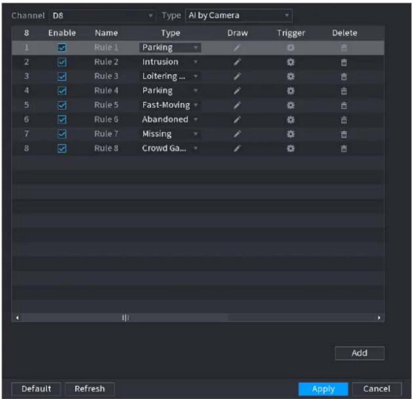
text_image
Channel D8 Type AI by Camera 8 Enable Name Type Draw Trigger Delete 1 ✓ Rule 1 Parking ✓ 2 ✓ Rule 2 Intrusion ✓ 3 ✓ Rule 3 Loitering ... ✓ 4 ✓ Rule 4 Parking ✓ 5 ✓ Rule 5 Fast-Moving ✓ 6 ✓ Rule 6 Abandoned ✓ 7 ✓ Rule 7 Missing ✓ 8 ✓ Rule 8 Crowd Ga... ✓ Add Default Refresh Apply CancelStep 2 Draw the detection rule.
1) Click to draw the rule on the surveillance video. See Figure 4-141.
Figure 4-141
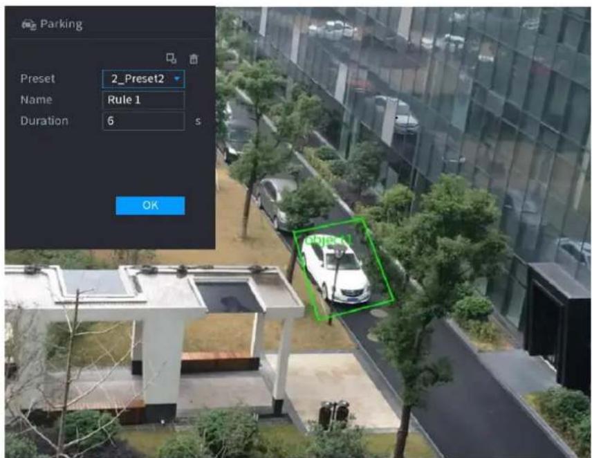
text_image
Parking Preset 2_Preset2 Name Rule 1 Duration 6 s OK2) Set parameters. See Table 4-35.
Table 4-35
| Parameter | Description |
| Preset | Set the preset point for IVS detection according to the actual needs. |
| Name | Customize the rule name. |
| Duration | Set the minimum time that the object stays until the alarm is triggered. |
| Filter target | Click  filter the target. Check the blue wireframe and adjust the size of the area with the mouse.Each rule can set 2 target filters (maximum size and minimum size), that is, when the passing target is smaller than the minimum target or larger than the maximum target, no alarm will be generated. The maximum size should not be smaller than the minimum size. filter the target. Check the blue wireframe and adjust the size of the area with the mouse.Each rule can set 2 target filters (maximum size and minimum size), that is, when the passing target is smaller than the minimum target or larger than the maximum target, no alarm will be generated. The maximum size should not be smaller than the minimum size. |
3) Draw a rule. Left click mouse to draw a zone, until you draw a rectangle, you can right click mouse.
4) Click OK to complete the rule setting.

Step 3 Click, you can refer to the "4.7.2.4.1 Tripwire" to set other parameters.
Step 4 Click Apply to complete the setup.
4.7.2.4.7 Missing Object Detection
System generates an alarm when there is missing object in the specified zone.
Step 1 In the Type drop-down list, select Missing Object.
The interface is shown as below. See Figure 4-142.
Figure 4-142
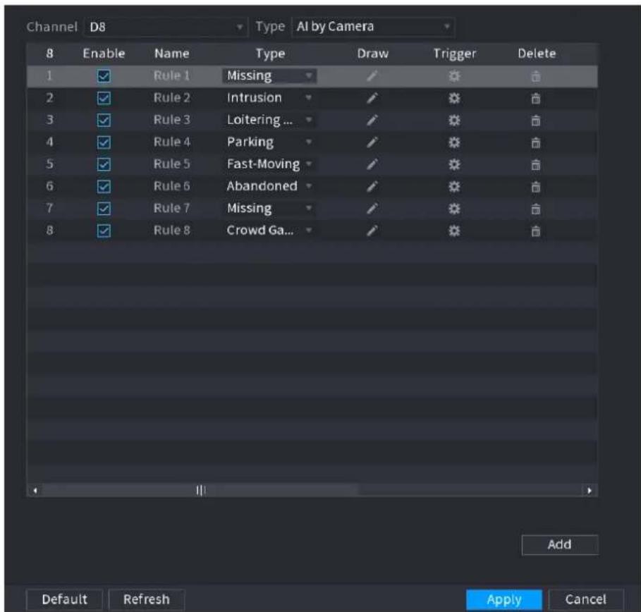
text_image
Channel D8 Type AI by Camera 8 Enable Name Type Draw Trigger Delete 1 ✓ Rule 1 Missing ✓ ❄ ❄ ❄ 2 ✓ Rule 2 Intrusion ✓ ❄ ❄ ❄ 3 ✓ Rule 3 Loitering ... ✓ ❄ ❄ ❄ 4 ✓ Rule 4 Parking ✓ ❄ ❄ ❄ 5 ✓ Rule 5 Fast-Moving ✓ ❄ ❄ ❄ 6 ✓ Rule 6 Abandoned ✓ ❄ ❄ ❄ 7 ✓ Rule 7 Missing ✓ ❄ ❄ ❄ 8 ✓ Rule 8 Crowd Ga... ✓ ❄ ❄ ❄ Add Default Refresh Apply CancelStep 2 Draw the detection rule.
1) Click to draw the rule on the surveillance video. See Figure 4-143.
Figure 4-143
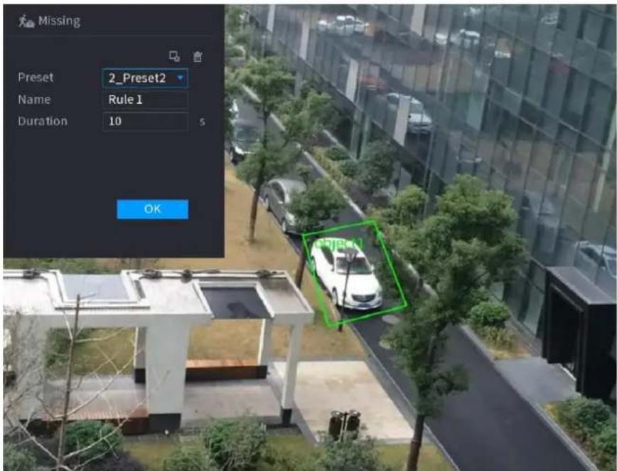
text_image
Missing Preset 2_Preset2 Name Rule 1 Duration 10 5 OK2) Set parameters. See Table 4-36.
Table 4-36
| Parameter | Description |
| Preset | Set the preset point for IVS detection according to the actual needs. |
| Name | Customize the rule name. |
| Duration | Set the minimum time that the object stays until the alarm is triggered. |
| Filter target | Click  filter the target. Check the blue wireframe and adjust the size of the area with the mouse.Each rule can set 2 target filters (maximum size and minimum size), that is, when the passing target is smaller than the minimum target or larger than the maximum target, no alarm will be generated. The maximum size should not be smaller than the minimum size. filter the target. Check the blue wireframe and adjust the size of the area with the mouse.Each rule can set 2 target filters (maximum size and minimum size), that is, when the passing target is smaller than the minimum target or larger than the maximum target, no alarm will be generated. The maximum size should not be smaller than the minimum size. |
3) Draw a rule. Left click mouse to draw a zone, until you draw a rectangle, you can right click mouse.
4) Click OK to complete the rule setting.

Step 3 Click, you can refer to the "4.7.2.4.1 Tripwire" to set other parameters.
Step 4 Click Apply to complete the setup.
4.7.2.4.8 Loitering Detection
System can generate an alarm once the object is staying in the specified zone longer than the threshold.
Step 1 In the Type drop-down list, select Loitering Detection.
The interface is shown as below. See Figure 4-144.
Figure 4-144
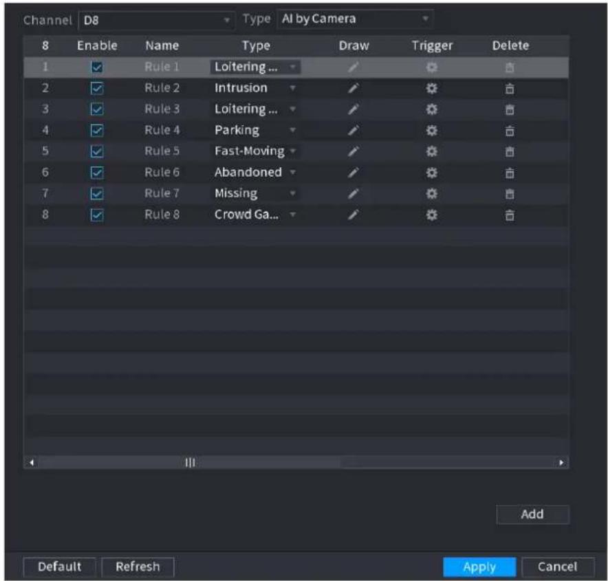
text_image
Channel D8 Type AI by Camera 8 Enable Name Type Draw Trigger Delete 1 ✓ Rule 1 Loitering ... ✓ ✓ ✓ ✓ 2 ✓ Rule 2 Intrusion ✓ ✓ ✓ ✓ ✓ 3 ✓ Rule 3 Loitering ... ✓ ✓ ✓ ✓ ✓ 4 ✓ Rule 4 Parking ✓ ✓ ✓ ✓ ✓ 5 ✓ Rule 5 Fast-Moving ✓ ✓ ✓ ✓ ✓ 6 ✓ Rule 6 Abandoned ✓ ✓ ✓ ✓ ✓ 7 ✓ Rule 7 Missing ✓ ✓ ✓ ✓ ✓ 8 ✓ Rule 8 Crowd Ga... ✓ ✓ ✓ ✓ ✓ Add Default Refresh Apply CancelStep 2 Draw the detection rule.
1) Click to draw the rule on the surveillance video. See Figure 4-145.
Figure 4-145
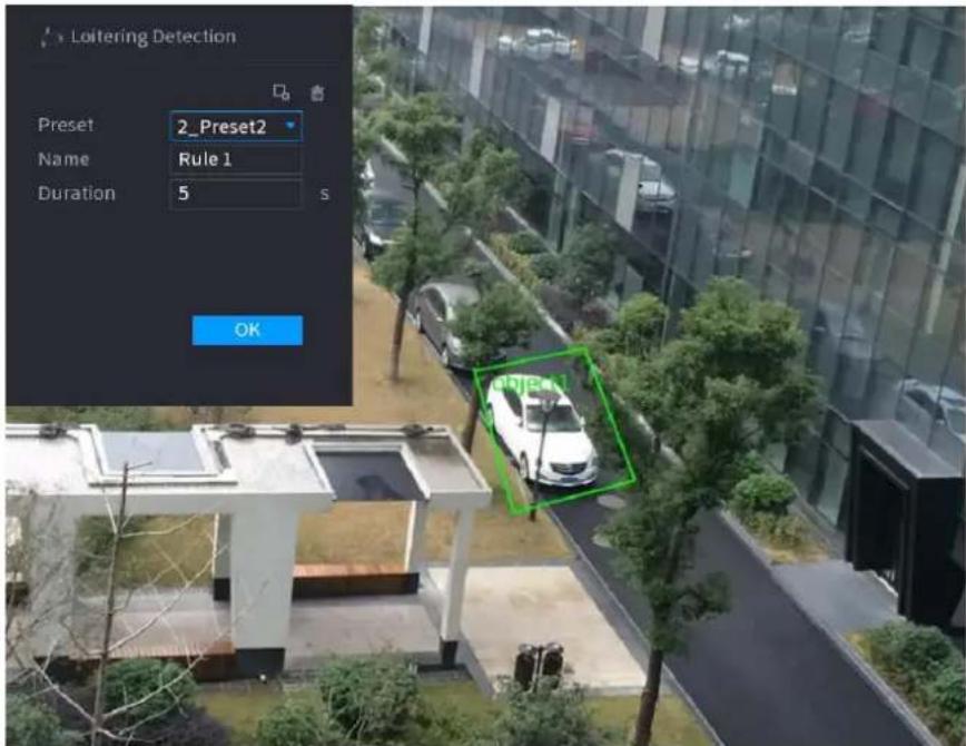
text_image
Loitering Detection Preset 2_Preset2 Name Rule 1 Duration 5 s OK2) Set parameters. See Table 4-37.
Table 4-37
| Parameter | Description |
| Preset | Set the preset point for IVS detection according to the actual needs. |
| Name | Customize the rule name. |
| Duration | Set the minimum time that the object stays until the alarm is triggered. |
| Filter target | Click  filter the target. Check the blue wireframe and adjust the size of the area with the mouse.Each rule can set 2 target filters (maximum size and minimum size), that is, when the passing target is smaller than the minimum target or larger than the maximum target, no alarm will be generated. The maximum size should not be smaller than the minimum size. filter the target. Check the blue wireframe and adjust the size of the area with the mouse.Each rule can set 2 target filters (maximum size and minimum size), that is, when the passing target is smaller than the minimum target or larger than the maximum target, no alarm will be generated. The maximum size should not be smaller than the minimum size. |
3) Draw a rule. Left click mouse to draw a zone, until you draw a rectangle, you can right click mouse.
4) Click OK to complete the rule setting.

Step 3 Click, you can refer to the "4.7.2.4.1 Tripwire" to set other parameters.
Step 4 Click Apply to complete the setup.
4.7.2.5 Video Structuring (Metadata)
The device can detect and extract key features from the human body, motor vehicle, and non-motor vehicles in the video, and then build a structured database. You can search any target you need with these features.
After enable the video structuring function, the corresponding smart plan can become valid.
Preparations
Make sure the connected camera supports video structuring (metadata) function.
Step 1 Select Main Menu > AI > PARAMETERS > VIDEO STRUCTURING.
The VIDEO STRUCTURING interface is displayed. See Figure 4-146.
Figure 4-146
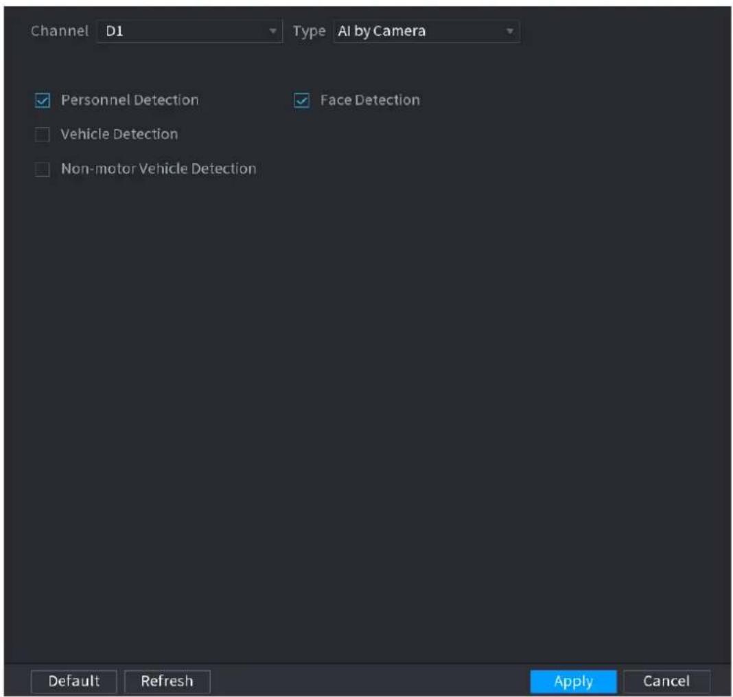
text_image
Channel D1 Type AI by Camera Personnel Detection Face Detection Vehicle Detection Non-motor Vehicle Detection Default Refresh Apply CancelStep 2 In the Channel list, select a channel that you want to configure video structuring function, and then enable it. See Table 4-38.
Table 4-38
| Parameter | Description |
| Human Detection | Select Human detection and then check the box to enable this function. |
| Face Detect | Select Face Detect and then check the box to enable this function. |
| Vehicle detection | Select Vehicle detection and then check the box to enable this function. |
| Non-motor Vehicle | Select Non-motor Vehicle and then check the box to enable this function. |
Step 3 Click Apply.
4.7.2.6 Crowd Distribution
Connecting to the front-end device that supports crowd distribution function, system can support the crowd distribution function. It supports crowd distribution event subscription and receive. It supports crowd distribution global and regional density settings, linkage alarm and triggered video storage, or upload the data to the platform. After connecting to the general network camera, the system adopts the algorithm to analyze the crowd density and trigger the
corresponding actions.
Step 1 Select Main Menu > AI > PARAMETERS > CROWD DISTRIBUTION. The CROWD DISTRIBUTION interface is displayed. See Figure 4-147.
Figure 4-147
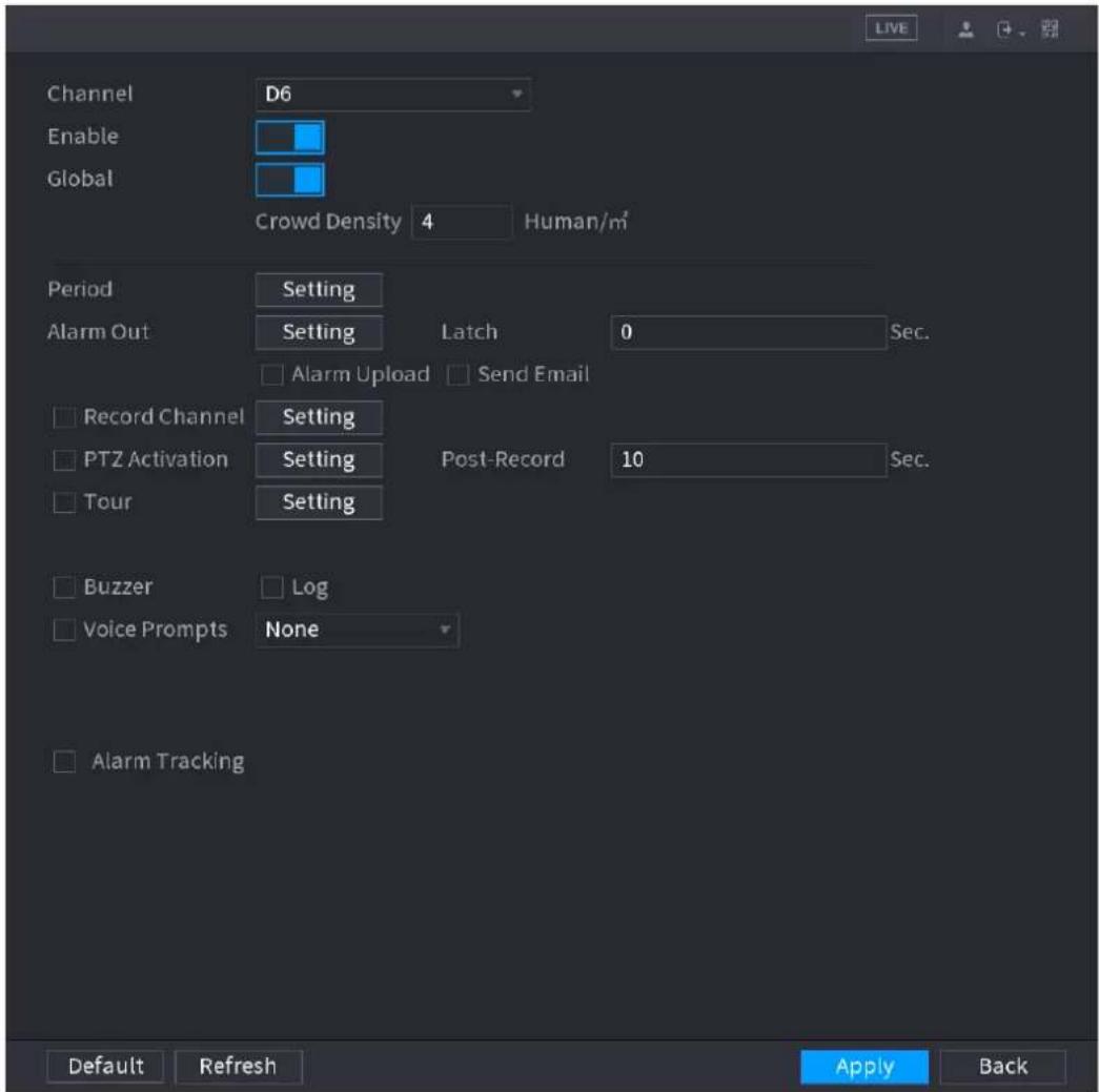
text_image
Channel Enable Global D6 Crowd Density 4 Human/m² Period Setting Alarm Out Setting Latch 0 Sec. Alarm Upload Send Email Record Channel Setting PTZ Activation Setting Post-Record 10 Sec. Tour Setting Buzzer Log Voice Prompts None Alarm Tracking Default Refresh Apply BackStep 2 Configure parameters. See Table 4-39.
Table 4-39
| Parameter | Description |
| Channel | Select a channel from the dropdown list. |
| Enable | Check the box to enable the function. |
| Global | Check the box to enable global crowd distribution alarm. |
| Crowd Density | Configure the alarm threshold. The default setup is 4 persons/ m^2 . The value ranges from 2 to 10. |
| Period | Configure the period and in the set time range, the corresponding configuration item will be linked to start the alarm. |
| Alarm Out | The alarm device (such as lights, sirens, etc.) is connected to the alarm output port. When an alarm occurs, the NVR device transmits the alarm information to the alarm device. |
| Latch | When the alarm ends, the alarm extended for a period of time. The time range is from 0 seconds to 300 seconds. |
| Alarm Upload | Select the check box. When an alarm occurs, the NVR device uploads an alarm signal to the network (including the alarm center).This function is for some series products only.You need to set the alarm center first. For details, see "4.12.9 Alarm Centre." |
| Send Email | Select the check box. When an alarm occurs, the NVR device sends an email to the set mailbox to notify the user.You need to set the email first. For details, see "4.12.6 Email." |
| Record Channel | Select the check box and select the needed recording channel (support multiple choices). When an alarm occurs, the NVR device activates the channel for recording.You need to enable intelligent recording and auto recording first. For details, see "4.1.4.6 Schedule." |
| PTZ Activation | Select the check box and clickSettingto select the channel and PTZ action.When an alarm occurs, the NVR device associates the channel to perform the corresponding PTZ action. For example, activate the PTZ in channel one to turn to the preset point X.Tripwire alarm supports to activate PTZ preset point only.You need to set the corresponding PTZ actions first, see "4.4.3 Configuring PTZ Functions." |
| Delay | At the end of the alarm, the recording extends for a period of time. The time range is from 10 seconds to 300 seconds. |
| Tour | Select the check box and select the channel for tour. When an alarm occurs, the local interface of the NVR device displays the selected channel screen.You need to set the time interval and mode for tour first, see "4.16.2 Tour."After the tour is over, the preview interface is restored to the screen split mode before the tour. |
| Log | Select the check box, the NVR device records the alarm information in the log when an alarm occurs. |
| Voice Prompts | Check the box and then select the corresponding audio file from the dropdown list. System plays the audio file when the alarm occurs.Refer to "4.17.1 File Manage" to add audio file first. |
| Buzzer | Select the check box to activate the buzzer when an alarm occurs. |
Step 3 Click Apply to complete the setup.
4.7.2.7 People Counting
System adopts video image and graphics analysis technology. System can calculate the entry/exit people amount in the specified zone on the video. It can generate an alarm when the amount has exceeded the threshold.
4.7.2.7.1 People Counting
Step 1 Select Main Menu > AI > PARAMETERS > PEOPLE COUNTING > PEOPLE COUNTING.
The PEOPLE COUNTING interface is displayed. See Figure 4-148.
Figure 4-148
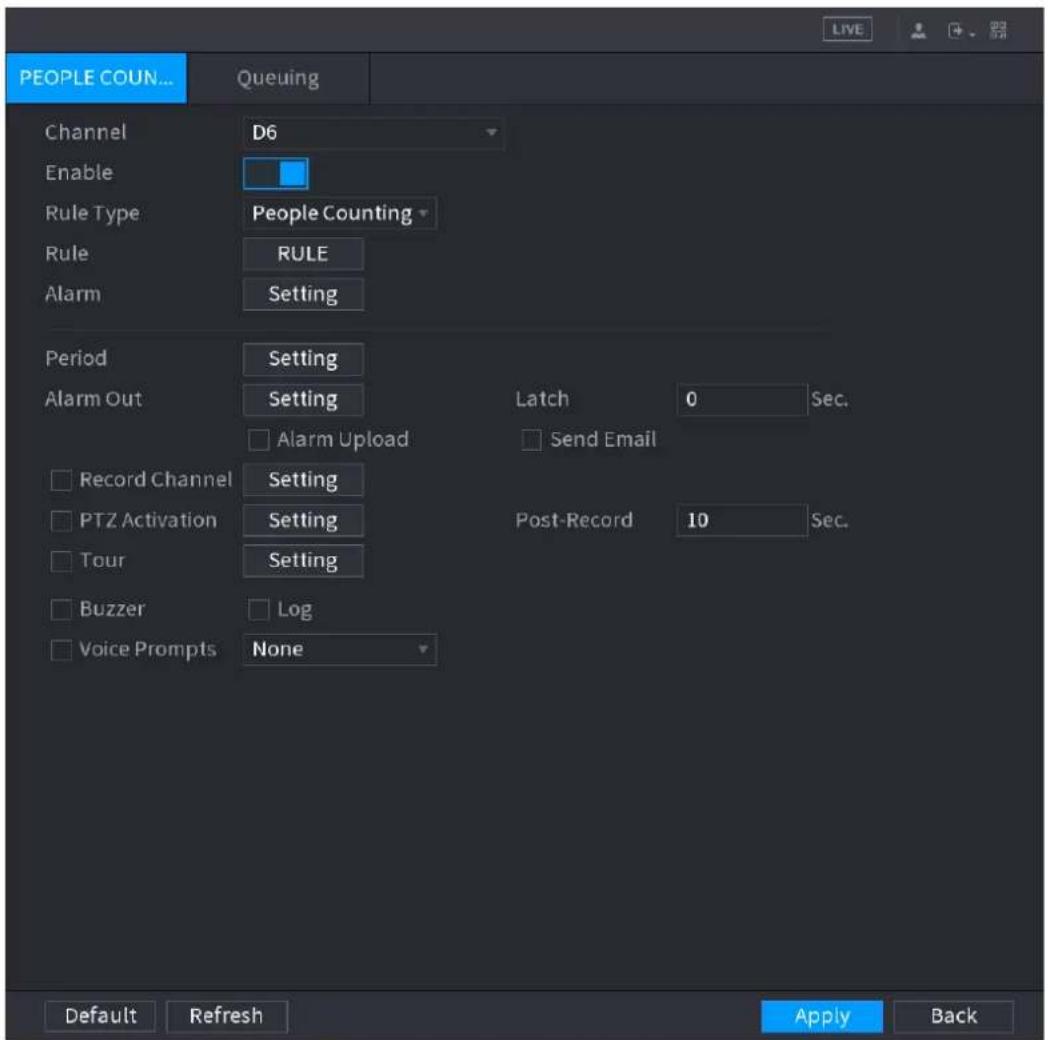
text_image
PEOPLE COUN... Queuing Channel D6 Enable Rule Type People Counting Rule RULE Alarm Setting Period Setting Alarm Out Setting Latch 0 Sec. □ Alarm Upload □ Send Email Record Channel Setting PTZ Activation Setting Post-Record 10 Sec. Tour Setting Buzzer Log Voice Prompts None Default Refresh Apply Back LIVEStep 2 Configure parameters. See Table 4-40.
Step 3 Click Apply to complete the setup.
Table 4-40
| Parameter | Description |
| Channel | Select a channel from the dropdown list. |
| Enable | Check the box to enable the function. |
| Rule Type | Select a people counting rule type. |
| Rule | Click RULE to set statistics region, name, direction. |
| Alarm | Click Setting to set alarm parameters.OSD Overlay: Check the box here; you can view the people amount on the surveillance video.Entry No.: You can set people entry amount. System can generate an alarm once the amount has exceeded the threshold.Exit No.: You can set people exit amount. System can generate an alarm once the amount has exceeded the threshold.Remaining No.: You can set people staying amount in the zone. System can generate an alarm once the amount has exceeded the threshold. |
| Period | Configure the period and in the set time range, the corresponding configuration item will be linked to start the alarm. |
| Alarm Out | The alarm device (such as lights, sirens, etc.) is connected to the alarm output port. When an alarm occurs, the NVR device transmits the alarm information to the alarm device. |
| Latch | When the alarm ends, the alarm extended for a period of time. The time range is from 0 seconds to 300 seconds. |
| Alarm Upload | Select the check box. When an alarm occurs, the NVR device uploads an alarm signal to the network (including the alarm center).This function is for some series products only.You need to set the alarm center first. For details, see "4.12.9 Alarm Centre." |
| Send Email | Select the check box. When an alarm occurs, the NVR device sends an email to the set mailbox to notify the user.You need to set the email first. For details, see "4.12.6 Email." |
| Record Channel | Select the check box and select the needed recording channel (support multiple choices). When an alarm occurs, the NVR device activates the channel fo recording.You need to enable intelligent recording and auto recording first. For details, see "4.1.4.6 Schedule." |
| PTZ Activation | Select the check box and click Setting to select the channel and PTZ action. When an alarm occurs, the NVR device associates the channel to perform the corresponding PTZ action. For example, activate the PTZ in channel one to turn to the preset point X.Tripwire alarm supports to activate PTZ preset point only.You need to set the corresponding PTZ actions first, see "4.4.3 Configuring PTZ Functions." |
| Delay | At the end of the alarm, the recording extends for a period of time. The time range is from 10 seconds to 300 seconds. |
| Tour | Select the check box and select the channel for tour. When an alarm occurs, the local interface of the NVR device displays the selected channel screen.You need to set the time interval and mode for tour first, see "4.16.2 Tour."After the tour is over, the preview interface is restored to the screen split mode before the tour. |
| Log | Select the check box, the NVR device records the alarm information in the log when an alarm occurs. |
| Voice Prompts | Check the box and then select the corresponding audio file from the dropdown list. System plays the audio file when the alarm occurs.Refer to "4.17.1 File Manage" to add audio file first. |
| Buzzer | Select the check box to activate the buzzer when an alarm occurs. |
4.7.2.7.2 Queuing
After connecting to the AI fisheye camera that supports the queuing function, system can realize the corresponding linkage actions once the people amount in the queue or the waiting time has trigger an alarm. Select a region first to set the corresponding actions. For the same line, the queue people number alarm and queue time alarm has the same linkage actions.
Step 1 Select Main Menu > AI > PARAMETERS > PEOPLE COUNTING > Queuing.
The Queuing interface is displayed. See Figure 4-149.
Figure 4-149
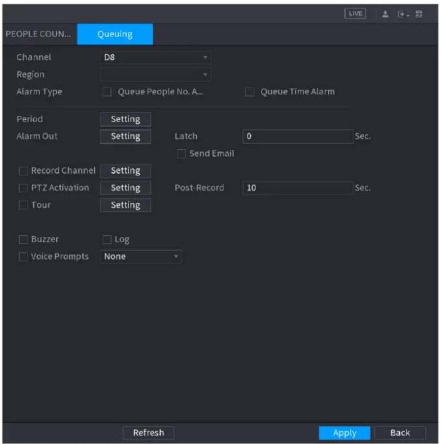
text_image
PEOPLE COUN... Queuing Channel D8 Region Alarm Type Queue People No. A... Queue Time Alarm Period Setting Alarm Out Setting Latch 0 Sec. Send Email Record Channel Setting PTZ Activation Setting Post-Record 10 Sec. Tour Setting Buzzer Log Voice Prompts None Refresh Apply BackStep 2 Configure parameters. See Table 4-41.
Step 3 Click Apply to complete the setup.
Table 4-41
| Parameter | Description |
| Channel | Select a channel from the dropdown list. |
| Region | Set queue detection region. |
| Alarm Type | Select Queue People No. Alarm or Queue Time Alarm. |
| Period | Configure the period and in the set time range, the corresponding configuration item will be linked to start the alarm. |
| Alarm Out | The alarm device (such as lights, sirens, etc.) is connected to the alarm output port. When an alarm occurs, the NVR device transmits the alarm information to the alarm device. |
| Latch | When the alarm ends, the alarm extended for a period of time. The time range is from 0 seconds to 300 seconds. |
| Alarm Upload | Select the check box. When an alarm occurs, the NVR device uploads an alarm signal to the network (including the alarm center).This function is for some series products only.You need to set the alarm center first. For details, see "4.12.9 Alarm Centre." |
| Send Email | Select the check box. When an alarm occurs, the NVR device sends an email to the set mailbox to notify the user.You need to set the email first. For details, see "4.12.6 Email." |
| Record Channel | Select the check box and select the needed recording channel (support multiple choices). When an alarm occurs, the NVR device activates the channel for recording.You need to enable intelligent recording and auto recording first. For details, see "4.1.4.6 Schedule." |
| PTZ Activation | Select the check box and click Setting to select the channel and PTZ action. When an alarm occurs, the NVR device associates the channel to perform the corresponding PTZ action. For example, activate the PTZ in channel one to turn to the preset point X.Tripwire alarm supports to activate PTZ preset point only.You need to set the corresponding PTZ actions first, see "4.4.3 Configuring PTZ Functions." |
| Delay | At the end of the alarm, the recording extends for a period of time. The time range is from 10 seconds to 300 seconds. |
| Tour | Select the check box and select the channel for tour. When an alarm occurs, the local interface of the NVR device displays the selected channel screen.You need to set the time interval and mode for tour first, see "4.16.2 Tour."After the tour is over, the preview interface is restored to the screen split mode before the tour. |
| Log | Select the check box, the NVR device records the alarm information in the log when an alarm occurs. |
| Voice Prompts | Check the box and then select the corresponding audio file from the dropdown list. System plays the audio file when the alarm occurs.Refer to "4.17.1 File Manage" to add audio file first. |
| Buzzer | Select the check box to activate the buzzer when an alarm occurs. |
4.7.2.8 Heat map
Heat map technology can monitor the active objects distribution status on the specified zone during a period of time, and use the different colors to display on the heat map.
Step 1 Select Main Menu > AI > PARAMETERS > HEAT MAP.
The HEAT MAP interface is displayed. See Figure 4-150.
Figure 4-150
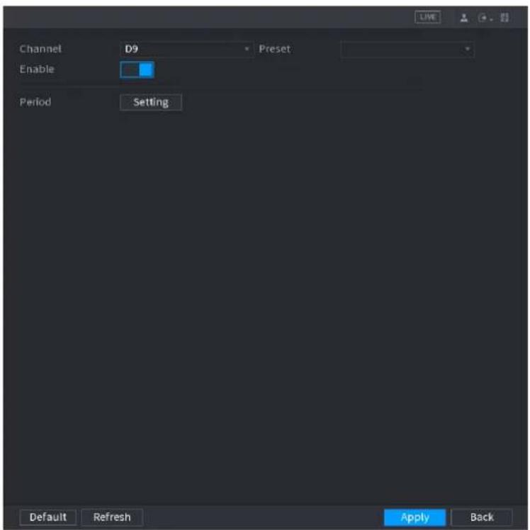
text_image
Channel D9 Enable Period Setting Default Refresh Apply BackStep 2 Select a channel number and then check the box to enable the function.
Step 3 Click Setting button.
The Setting interface is displayed. See Figure 4-151.
Figure 4-151
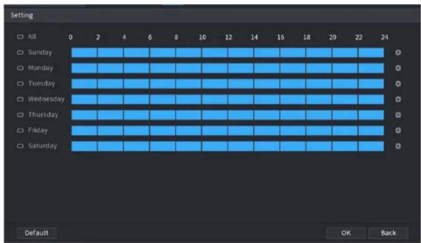
text_image
Setting All 0 2 4 6 8 10 12 14 15 18 20 22 24 Sunday Monday Tuesday Wednesday Thursday Friday Saturday Default OK BackStep 4 Set arm/disarm period. There are two modes for you to set the period so that the system can detect the specified zone.
- Define the period by drawing.
- Select the corresponding date and then use mouse to drag the bar to set period.
Define for the whole week: Click ☐ next to All, all the icon switches to ☑, you can define the period for all the days simultaneously.
☐ Define for several days of a week: Click before each day one by one, the icon switches to You can define the period for the selected days simultaneously.
- Define the period by editing.
1) Click the 📄 of the corresponding date, and then set the period on the pop-up interface. Click OK to save.
◇ There are six periods for you to set for each day.
Under Copy, select All to apply the settings to all the days of a week, or select specific day(s) that you want to apply the settings to.
2) Click Apply to save the settings.
Step 5 Click Apply button to complete setup.

After set the heat map parameters, go to Main Menu > INFO > EVENT > HEAT MAP to view heat map report. Refer to "4.7.1.8 Heat map" for detailed setup information.
4.7.2.9 ANPR
System uses the video recognition technology to extract the plate number on the surveillance video and then compare it with the specified plate information. System can trigger an alarm once there is a matched result.
You can set different plate recognition rule, alarm linkage actions in different environments (blacklist, whitelist and regular).
Step 1 Select Main Menu > AI > PARAMETERS > ANPR.
The ANPR interface is displayed. See Figure 4-152.
Figure 4-152
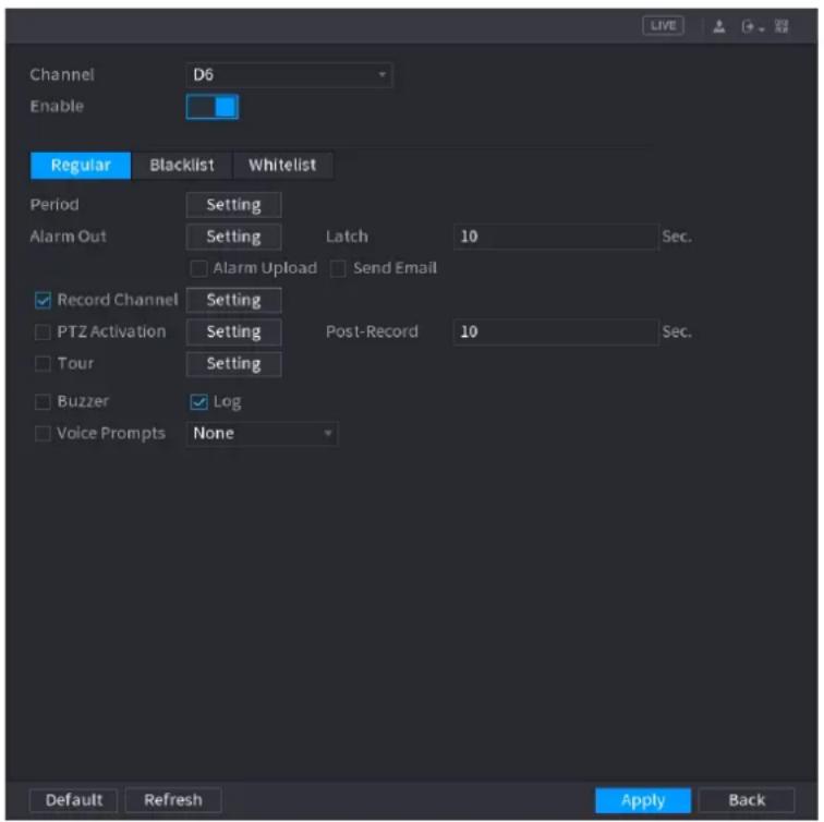
text_image
Channel Enable Regular Blacklist Whitelist Period Setting Alarm Out Setting Latch 10 Sec. Alarm Upload Send Email Record Channel Setting PTZ Activation Setting Post-Record 10 Sec. Tour Setting Buzzer Log Voice Prompts None Default Refresh Apply BackStep 2 Select the Enable check box to enable ANPR.
Step 3 Click Regular (default), Blacklist or Whitelist tab to configure it.

Before activate blacklist alarm or whitelist alarm, you need to add the corresponding plate information. Refer to "4.7.3.2 B/W List" for detailed information.
● Regular: Device triggers an alarm when it detects any plate number.
- Blacklist: Device triggers an alarm when it detects plate number in the blacklist.
- Whitelist: Device triggers an alarm when it detects plate number in the whitelist.
Step 4 Set parameters. See Table 4-42.
Step 5 Click Apply.
Table 4-42
| Parameter | Description |
| Period | Configure the period and in the set time range, the corresponding configuration item will be linked to start the alarm. |
| Alarm Out | The alarm device (such as lights, sirens, etc.) is connected to the alarm output port. When an alarm occurs, the NVR device transmits the alarm information to the alarm device. |
| Latch | When the alarm ends, the alarm extended for a period of time. The time range is from 0 seconds to 300 seconds. |
| Alarm Upload | Select the check box. When an alarm occurs, the NVR device uploads an alarm signal to the network (including the alarm center).This function is for some series products only.You need to set the alarm center first. For details, see "4.12.9 Alarm Centre." |
| Send Email | Select the check box. When an alarm occurs, the NVR device sends an email to the set mailbox to notify the user.You need to set the email first. For details, see "4.12.6 Email." |
| Record Channel | Select the check box and select the needed recording channel (support multiple choices). When an alarm occurs, the NVR device activates the channel for recording.You need to enable intelligent recording and auto recording first. For details, see "4.1.4.6 Schedule." |
| PTZ Activation | Select the check box and clickSettingto select the channel and PTZ action.When an alarm occurs, the NVR device associates the channel to perform the corresponding PTZ action. For example, activate the PTZ in channel one to turn to the preset point X.Tripwire alarm supports to activate PTZ preset point only.You need to set the corresponding PTZ actions first, see "4.4.3 Configuring PTZ Functions." |
| Delay | At the end of the alarm, the recording extends for a period of time. The time range is from 10 seconds to 300 seconds. |
| Tour | Select the check box and select the channel for tour. When an alarm occurs, the local interface of the NVR device displays the selected channel screen.You need to set the time interval and mode for tour first, see "4.16.2 Tour."After the tour is over, the preview interface is restored to the screen split mode before the tour. |
| Log | Select the check box, the NVR device records the alarm information in the log when an alarm occurs. |
| Voice Prompts | Check the box and then select the corresponding audio file from the dropdown list. System plays the audio file when the alarm occurs.Refer to "4.17.1 File Manage" to add audio file first. |
| Buzzer | Select the check box to activate the buzzer when an alarm occurs. |
4.7.3 Database
After you successfully set the face library, the detected human face can compare with the image on the face library. The face library settings include create face library, add human face and human face modeling.

For privacy reason, the human face is pixelated.
4.7.3.1 Creating Human Face Library
Step 1 Select Main Menu > AI > DATABASE > FACE LIBRARY.
The FACE LIBRARY interface is displayed. See Figure 4-153.
Figure 4-153
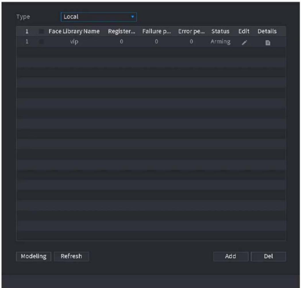
text_image
Type Local 1 Face Library Name Register... Failure p... Error pe... Status Edit Details 1 vip 0 0 0 Arming Modeling Refresh Add DelStep 2 Select a channel and then click Add. System displays Add interface. See Figure 4-154.
Figure 4-154

text_image
Add Face Library Name Save BackStep 3 Input human face library name and then click Save. System successfully saves the face library.
Adding Face Pictures
You can add face pictures to the existing libraries one by one or by batch, or add from the detected faces.

To add face pictures one by one or by batch, you need to get the pictures from the USB storage device. The picture size should be smaller than 256K with resolution between 200×200–6000×5000.
Adding One Face Picture
You can add one face picture to the database. It is for the scenario that the registered human face picture amount is small.
Step 1 Select Main Menu > AI > DATABASE > FACE LIBRARY.
The FACE LIBRARY interface is displayed.
Step 2 Click of the library that you want to configure. The Details interface is displayed. See Figure 4-155.
Figure 4-155
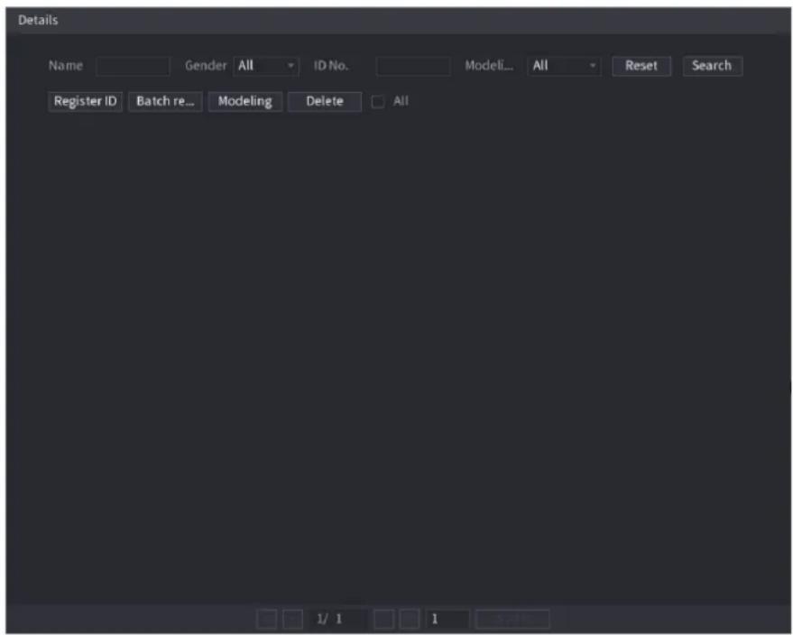
text_image
Details Name Gender All ID No. Modeli... All Reset Search Register ID Batch re... Modeling Delete All 1/ 1 1 OptionsStep 3 Click Register ID.
The Register ID interface is displayed. See Figure 4-156.
Figure 4-156
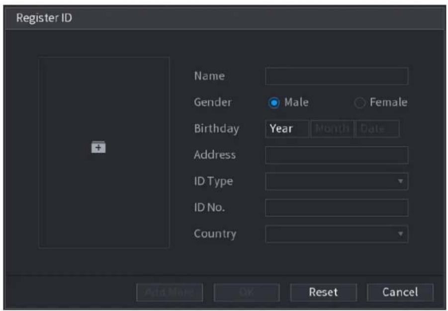
text_image
Register ID Name Gender Male Female Birthday Year Month Date Address ID Type ID No. Country Add More OK Reset CancelStep 4 Click to add a face picture.
The Browse interface is displayed. See Figure 4-157.
Figure 4-157
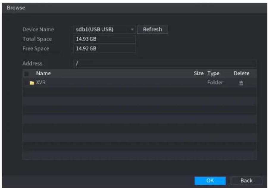
text_image
Browse Device Name sdb1(USB USB) Refresh Total Space 14.93 GB Free Space 14.92 GB Address Name Size Type Delete XVR Folder OK BackStep 5 Select a face picture and enter the registration information. See Figure 4-158.
Figure 4-158
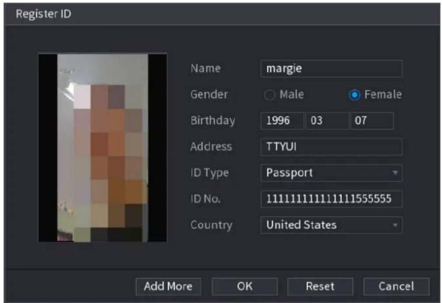
text_image
Register ID Name margie Gender Male Female Birthday 1996 03 07 Address TTYUI ID Type Passport ID No. 11111111111111155555 Country United States Add More OK Reset CancelStep 6 Click OK.
The system prompts the registration is successful.
Step 7 On the Details interface, click Search.
The system prompts modeling is successful. See Figure 4-159.

If the system prompts the message indicating modeling is in process, wait a while and then click Search again. If modeling is failed, the registered face picture cannot be used for face recognition.
Figure 4-159
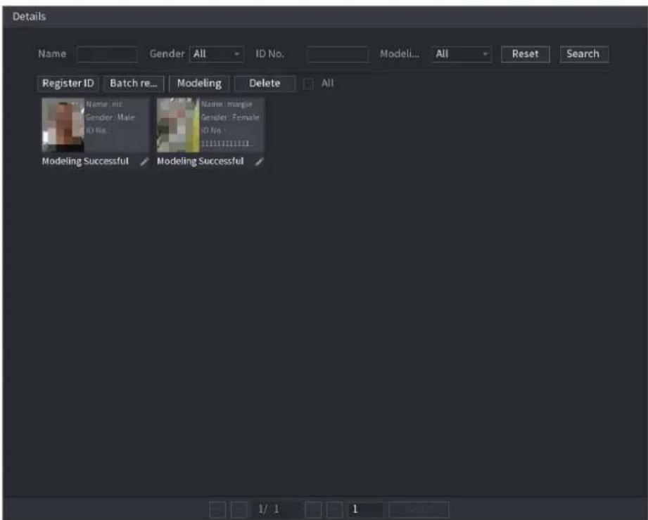
text_image
Details Name Gender All ID No. Modeli... All Reset Search Register ID Batch re... Modeling Delete All Name: nic Name: mangie Gender: Male Gender: Female ID No. ID No. 11111111111111111111111111111111111111111111111111111111111111111111111111111111111111111111111111110000000000000000000000000000000000000000000000000000000000000000000000000000000000000000000000000000 Modeling Successful Modeling SuccessfulAdding Face Pictures in Batch
System supports batch add if you want to import several human face image at the same time.
Step 1 Give a name to the face picture by referring to the following table. See Table 4-43.
Table 4-43
| Naming format | Description |
| Name | Enter the name. |
| Gender | Enter 1 or 2. 1 represents male, and 2 represents female. |
| Birthday | Enter numbers in the format of yyyy-mm-dd. |
| Country | Enter the abbreviation of country. For example, CN for China. |
| ID Type | 1 represents ID card; 2 represents passport; 3 represents military officer password. |
| ID No. | Enter the ID number. |
| Address | Enter the address. |
Step 2 Select Main Menu > AI > DATABASE > FACE LIBRARY.
The FACE LIBRARY interface is displayed.
Step 3 Click of the library that you want to configure. The Details interface is displayed. See Figure 4-155.
Step 4 On the Details interface, click Batch register. The Batch register interface is displayed. See Figure 4-160.
Figure 4-160
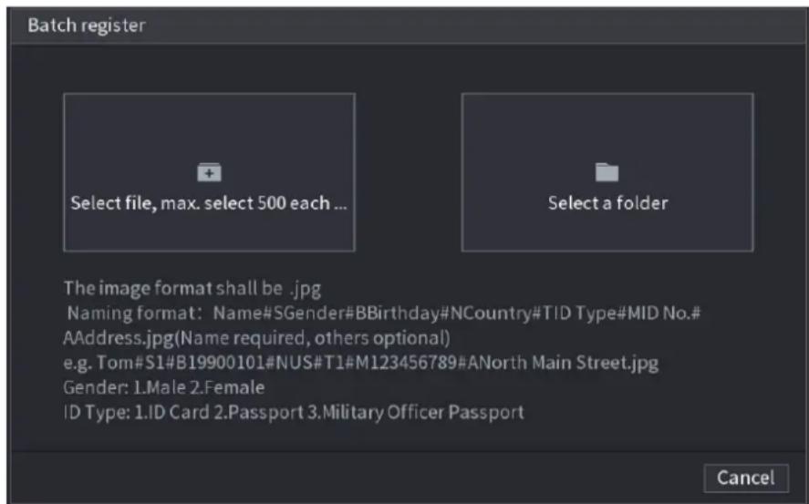
text_image
Batch register Select file, max. select 500 each ... Select a folder The image format shall be .jpg Naming format: Name#SGender#BBirthday#NCountry#TID Type#MID No.# AAddress.jpg(Name required, others optional) e.g. Tom#S1#B19900101#NUS#T1#M123456789#ANorth Main Street.jpg Gender: 1.Male 2.Female ID Type: 1.ID Card 2.Passport 3.Military Officer Passport CancelStep 5 Click Select file, max select 500 each time or Select a folder to import face pictures.
Step 6 Click OK to complete batch registration.
4.7.3.2 Black/whitelist
To manage vehicle management, you can add the corresponding plate number on the blacklist or whitelist. System can compare the detected plate information with the plate on the
blacklist/whitelist and then trigger the corresponding alarm linkage.
After enable black/whitelist, on the preview interface, the plate in the blacklist is displayed as red on the plate list, the plate in the whitelist is displayed as green on the plate list. For the plate not in the black/whitelist, the plate is displayed as white.
Adding B/W List
Step 1 Select Main Menu > AI > DATABASE > B/WLIST. The B/W List interface is displayed. See Figure 4-161.
Figure 4-161
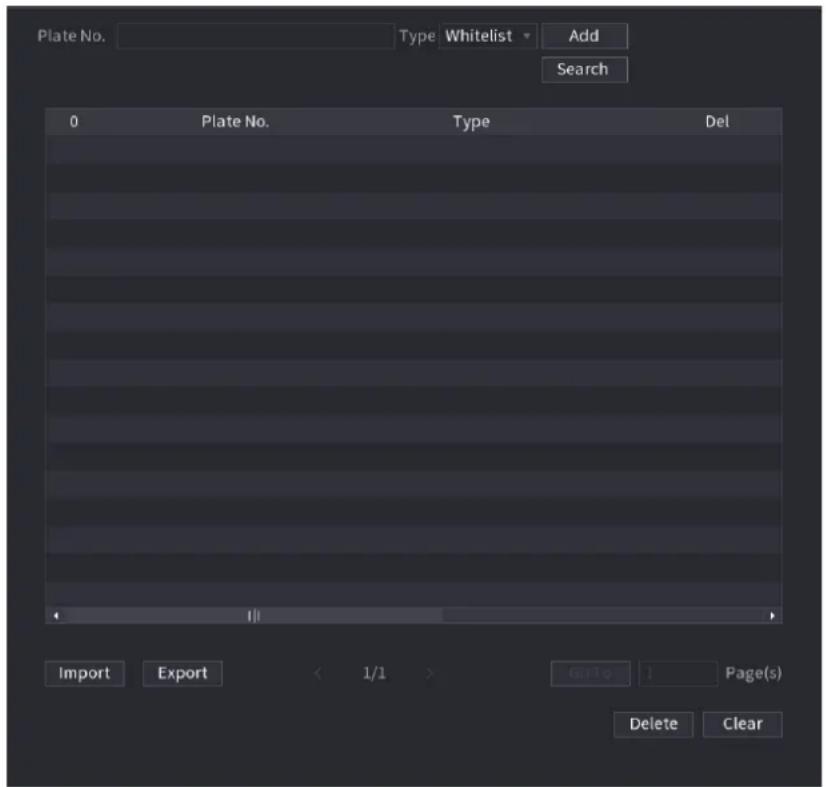
text_image
Plate No. Type Whitelist Add Search 0 Plate No. Type Del Import Export < 1/1 > Guide 1 Page(s) Delete ClearStep 2 Set plate information and then select Blacklist or Whitelist.
Step 3 Click Add.
Deleting Black/Whitelist
Set type as Whitelist, Blacklist, or All, and then click Search. System displays black/whitelist information. See Figure 4-162.
- On the searched results list, check the box before the plate number and then click Delete, or click the of the corresponding plate number, you can delete the plate information on the black/whitelist.
- Click Clear to delete all plate information on the black/whitelist.
Figure 4-162
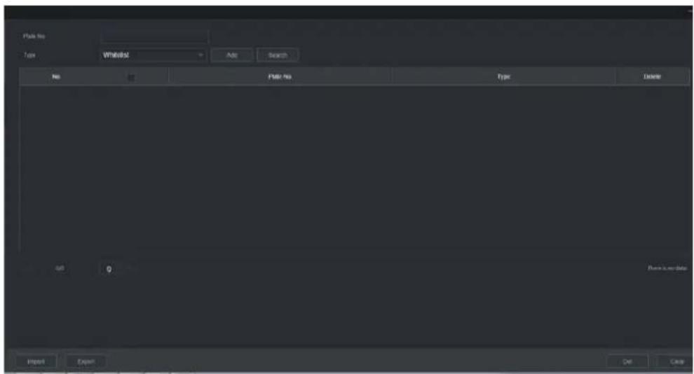
text_image
Static No Type StaticNo Add Search No Add Static No Type Delete 0 0 Finish is run data Import Export Exit CancelImport/Export Black/whitelist
System supports export black/whitelist to the USB device, or import black/whitelist from the USB device. System supports .csv or .xlsx file. The export file format is .csv.
- Import black/whitelist: Click Import and then select the corresponding file, click Browse to import the file.
- Export black/whitelist: Click Export and then select the file storage path and then click Save.
4.8 Event Manager
4.8.1 Alarm Info
You can search, view and back up the alarm information.
Step 1 Select Main Menu > ALARM > ALARM INFO.
The ALARM INFO interface is displayed. See Figure 4-163.
Figure 4-163
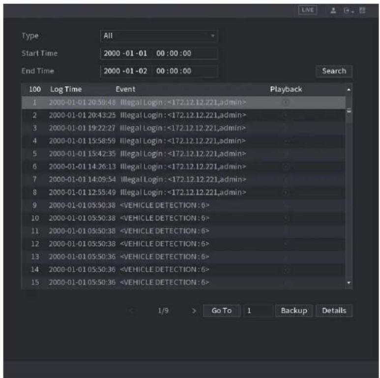
text_image
Type All Start Time 2000 -01 -01 00 :00 :00 End Time 2000 -01 -02 00 :00 :00 Search 100 Log Time Event Playback 1 2000-01-01 20:59:48 Illegal Login :<172.12.12.221,admin> 2 2000-01-01 20:43:25 Illegal Login :<172.12.12.221,admin> 3 2000-01-01 19:22:27 Illegal Login :<172.12.12.221,admin> 4 2000-01-01 15:58:59 Illegal Login :<172.12.12.221,admin> 5 2000-01-01 15:42:35 Illegal Login :<172.12.12.221,admin> 6 2000-01-01 14:26:13 Illegal Login :<172.12.12.221,admin> 7 2000-01-01 14:09:54 Illegal Login :<172.12.12.221,admin> 8 2000-01-01 12:55:49 Illegal Login :<172.12.12.221,admin> 9 2000-01-01 05:50:38Step 4 In the Type list, select the event type; In the Start Time box and End Time box, enter the specific time.
Step 5 Click Search.
The search results are displayed.
Step 6 Click Backup to back up the search results into the external storage device.
NOTE
- Select an alarm event log and then click Backup to back up it to peripheral USB device.
- Select an alarm event log, click to play the recorded video of alarm event. Double-click a log or click Details to view the detailed information of the event.
4.8.2 Alarm Status
You can view NVR alarm event, and remote channel alarm event.
Select Main Menu > ALARM > ALARM STATUS, the ALARM STATUS interface is displayed. See Figure 4-164.
Figure 4-164
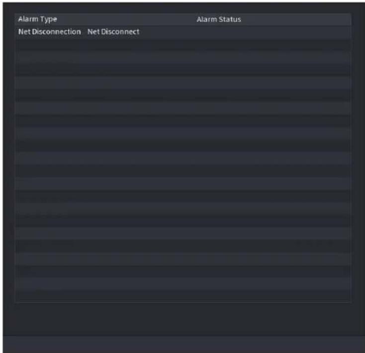
text_image
Alarm Type Net Disconnection Net Disconnect Alarm Status4.8.3 Alarm Input
Step 1 Select Main menu > ALARM > ALARM INPUT,
The ALARM INPUT interface is displayed. See Figure 4-165.
Step 2 There are four alarm types.
- Local alarm: After connect the alarm device to the NVR alarm input port, system can trigger the corresponding alarm operations when there is alarm signal from the alarm input port to the NVR.
● Network alarm: NVR trigger corresponding alarm operations when it receives the alarm signal via the network transmission. - IPC external alarm: When the network camera connected peripheral device has triggered an alarm, it can upload the alarm signal to the NVR via the network transmission. The system can trigger the corresponding alarm operations.
- IPC offline alarm: When the network connection between the NVR and the network camera is off, the system can trigger the corresponding alarm operations.
Figure 4-165
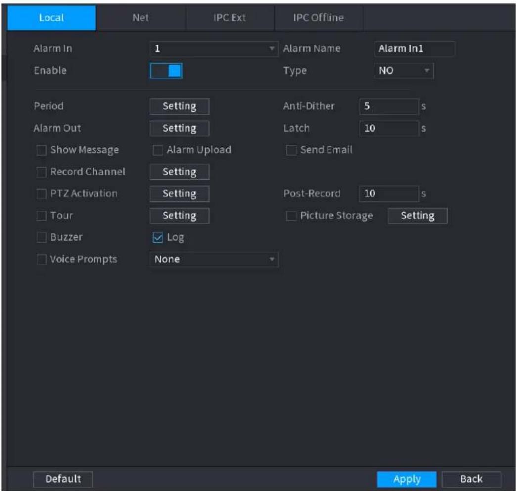
text_image
Local Net IPC Ext IPC Offline Alarm In 1 Alarm Name Alarm In1 Enable Type NO Period Setting Anti-Dither 5 s Alarm Out Setting Latch 10 s Show Message Alarm Upload Send Email Record Channel Setting Post-Record 10 s PTZ Activation Setting Tour Setting Picture Storage Setting Buzzer Log Voice Prompts None Default Apply BackStep 3 Set Alarm In channel number and then select the Enable check box to enable the function.
Step 4 Configure parameters. See Table 4-44.
Step 5 Click Apply.
Table 4-44
| Parameter | Description |
| Alarm in | Select a channel to set alarm. |
| Enable | Check the box to enable the function. |
| Alarm Name | Enter an alarm name. |
| Type | NO (normal open) or NC (normal close). |
| Period | Define a period during which the alarm is active. For details, see "Setting Period in 4.8.5.1 Motion Detect." |
| Alarm Out | The alarm device (such as lights, sirens, etc.) is connected to the alarm output port. When an alarm occurs, the NVR device transmits the alarm information to the alarm device. |
| Latch | When the alarm ends, the alarm extended for a period of time. The time range is from 0 seconds to 300 seconds. |
| Show Message | Check box to enable a pop-up message in your local host PC. |
| Alarm Upload | Select the check box. When an alarm occurs, the NVR device uploads an alarm signal to the network (including the alarm center).This function is for some series products only.You need to set the alarm center first. For details, see "4.12.9 Alarm Centre." |
| Send Email | Select the check box. When an alarm occurs, the NVR device sends an email to the set mailbox to notify the user.You need to set the email first. For details, see "4.12.6 Email." |
| Record Channel | Select the check box and select the needed recording channel (support multiple choices). When an alarm occurs, the NVR device activates the channel for recording.You need to enable intelligent recording and auto recording first. For details, see "4.1.4.6 Schedule." |
| PTZ Activation | Select the check box and clickSettingto select the channel and PTZ action. When an alarm occurs, the NVR device associates the channel to perform the corresponding PTZ action. For example, activate the PTZ in channel one to turn to the preset point X.Tripwire alarm supports to activate PTZ preset point only.You need to set the corresponding PTZ actions first, see "4.4.3 Configuring PTZ Functions." |
| Delay | At the end of the alarm, the recording extends for a period of time. The time range is from 10 seconds to 300 seconds. |
| Tour | Select the check box and select the channel for tour. When an alarm occurs, the local interface of the NVR device displays the selected channel screen.You need to set the time interval and mode for tour first, see "4.16.2 Tour."After the tour is over, the preview interface is restored to the screen split mode before the tour. |
| Snapshot | Select theSnapshotcheck box to take a snapshot of the selected channel.To use this function, selectMain Menu >CAMERA >ENCODE >Snapshot, in the Mode list, select Event (Trigger). |
| Log | Select the check box, the NVR device records the alarm information in the log when an alarm occurs. |
| VoicePrompts | Check the box and then select the corresponding audio file from the dropdown list. System plays the audio file when the alarm occurs.[IMAGE]Refer to "4.17.1 File Manage" to add audio file first. |
| Buzzer | Select the check box to activate the buzzer when an alarm occurs. |
4.8.4 Alarm Control
You can set proper alarm output (Auto/manual/off). Connect the alarm device to the system alarm output port, and set the mode as auto, system can trigger the corresponding operations when an alarm occurs.
● Auto: Once an alarm event occurs, system can generate an alarm.
● Manual: Alarm device is always on the alarming mode.
- Off: Disable alarm output function.
Step 1 Select Main Menu > ALARM > ALARM OUTPUT.
The ALARM OUTPUT interface is displayed. See Figure 4-166.
Figure 4-166
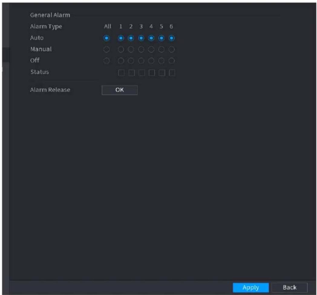
text_image
General Alarm Alarm Type All 1 2 3 4 5 6 Auto Manual Off Status Alarm Release OK Apply BackStep 2 Select the alarm mode of the alarm output channel.
- Click OK button of the Alarm Release, you can clear all alarm output statuses.
• View the alarm output status on the Status column.
Step 3 Click Apply.
4.8.5 Video Detection
The video detection adopts the computer image and graphics process technology. It can analyze the video and check there is considerable changing or not. Once video has changed considerably (such as there is any moving object, video is distorted), system can trigger the corresponding alarm activation operations.
Select Main menu > ALARM > VIDEO DETECTION >MOTION DETECT, you can see motion detect interface. See Figure 4-169. There are five detection types: motion detection, video loss, tampering, scene changing and PIR alarm.
4.8.5.1 Motion Detect
When the moving object appears and moves fast enough to reach the preset sensitivity value, the system activates the alarm.
Step 1 Select Main Menu > ALARM > VIDIEO DETECTION > Motion Detect.
The Motion Detect interface is displayed. See Figure 4-167.
Figure 4-167
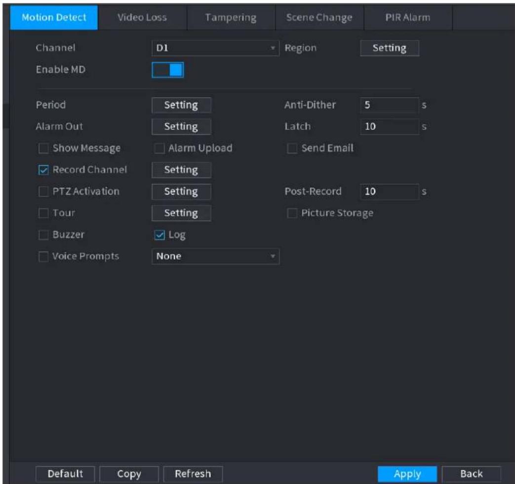
text_image
Motion Detect Video Loss Tampering Scene Change PIR Alarm Channel D1 Region Setting Enable MD Period Setting Anti-Dither 5 s Alarm Out Setting Latch 10 s Show Message Alarm Upload Send Email Record Channel Setting Post-Record 10 s PTZ Activation Setting Tour Setting Picture Storage Buzzer Log Voice Prompts None Default Copy Refresh Apply BackStep 2 Configure the settings for the motion detection parameters. See Table 4-45.
Table 4-45
| Parameter | Description |
| Channel | In the Channel list, select a channel to set the motion detection. |
| Region | Click Setting to define the motion detection region. |
| Enable MD | Enable or disable the motion detection function. Check the box  to enable the function. to enable the function. |
| Period | Define a period during which the motion detection is active. |
| Sensitivity | The higher the value is, the easier it is to trigger an alarm. But at the same time, the false alarm may occur. The default value is recommended. |
| Alarm Out | The alarm device (such as lights, sirens, etc.) is connected to the alarm output port. When an alarm occurs, the NVR device transmits the alarm information to the alarm device. |
| Latch | When the alarm ends, the alarm extended for a period of time. The time range is from 0 seconds to 300 seconds. |
| Show Message | Check box to enable a pop-up message in your local host PC. |
| Alarm Upload | Select the check box. When an alarm occurs, the NVR device uploads an alarm signal to the network (including the alarm center).This function is for some series products only.You need to set the alarm center first. For details, see "4.12.9 Alarm Centre." |
| Send Email | Select the check box. When an alarm occurs, the NVR device sends an email to the set mailbox to notify the user.You need to set the email first. For details, see "4.12.6 Email." |
| Record Channel | Select the check box and select the needed recording channel (support multiple choices). When an alarm occurs, the NVR device activates the channel for recording.You need to enable intelligent recording and auto recording first. For details, see "4.1.4.6 Schedule." |
| PTZ Activation | Select the check box and click Setting to select the channel and PTZ action. When an alarm occurs, the NVR device associates the channel to perform the corresponding PTZ action. For example, activate the PTZ in channel one to turn to the preset point X.Tripwire alarm supports to activate PTZ preset point only.You need to set the corresponding PTZ actions first, see "4.4.3 Configuring PTZ Functions." |
| Delay | At the end of the alarm, the recording extends for a period of time. The time range is from 10 seconds to 300 seconds. |
| Tour | Select the check box and select the channel for tour. When an alarm occurs, the local interface of the NVR device displays the selected channel screen.You need to set the time interval and mode for tour first, see "4.16.2 Tour."After the tour is over, the preview interface is restored to the screen split mode before the tour. |
| Snapshot | Select the Snapshot check box to take a snapshot of the selected channel.To use this function, select Main Menu > CAMERA > ENCODE > Snapshot, in the Mode list, select Event (Trigger). |
| Voice Prompts | Check the box and then select the corresponding audio file from the dropdown list. System plays the audio file when the alarm occurs.Refer to "4.17.1 File Manage" to add audio file first. |
| Buzzer | Select the check box to activate the buzzer when an alarm occurs. |
Step 3 Click Apply to save the settings.

- Click Default to restore the default setting.
- Click Copy, in the Copy dialog box, select the additional channel(s) that you want to copy the motion detection settings to, and then click Apply.
- Click Test to test the settings.
Setting the Motion Detection Region
Step 1 Next to Region, click Setting.
The region setting screen is displayed.
Step 2 Point to the middle top of the interface.
The setting interface is displayed. See Figure 4-168.
Figure 4-168
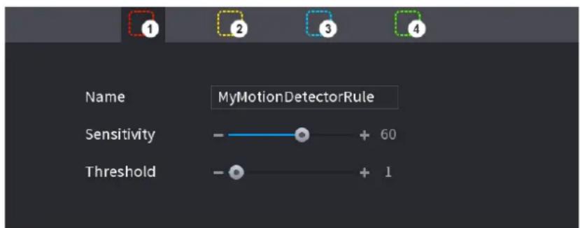
text_image
Name MyMotionDetectorRule Sensitivity + 60 Threshold + 1Step 3 Configure the regions settings. You can configure totally four regions.
1) Select one region, for example, click

2) Drag on the screen to select the region that you want to detect.
3) The selected area shows the color that represents the region.
4) Configure the parameters. See Table 4-46.
Table 4-46
| Parameter | Description |
| Name | Enter a name for the region. |
| Sensitivity | Every region of every channel has an individual sensitivity value.The bigger the value is, the easier the alarms can be activated. |
| Threshold | Adjust the threshold for motion detect. Every region of every channel has an individual threshold. |

When anyone of the four regions activates motion detect alarm, the channel where this region belongs to will activate motion detect alarm.
Step 4 Right-click on the screen to exit the region setting interface.
Step 5 On the Motion Detect interface, click Apply to complete the settings.
Setting Period

The system only activates the alarm in the defined period.
Step 1 Next to Period, click Setting.
The Setting interface is displayed. See Figure 4-169.
Figure 4-169
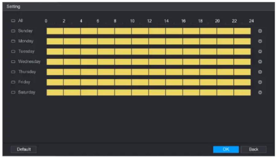
text_image
Setting All 0 2 4 6 8 10 12 14 16 18 20 22 24 Sunday Monday Tuesday Wednesday Thursday Friday Saturday Default OK BackStep 2 Define the motion detection period. By default, it is active all the time.
- Define the period by drawing.
☐ Define for a specified day of a week: On the timeline, click the half-hour blocks to select the active period.
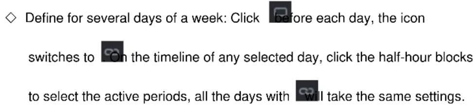
text_image
Define for several days of a week: Click before each day, the icon switches to On the timeline of any selected day, click the half-hour blocks to select the active periods, all the days with will take the same settings.
text_image
Define for all days of a week: Click All, all switches to On the timeline of any day, click the half-hour blocks to select the active periods, all the days will take the same settings.- Define the period by editing. Take Sunday as an example.
1) Click .
The Period interface is displayed. See Figure 4-170.
Figure 4-170
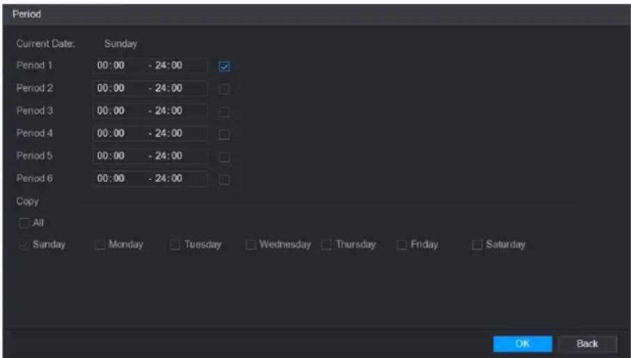
text_image
Period Current Date: Sunday Period 1 00:00 - 24:00 Period 2 00:00 - 24:00 Period 3 00:00 - 24:00 Period 4 00:00 - 24:00 Period 5 00:00 - 24:00 Period 6 00:00 - 24:00 Copy All Sunday Monday Tuesday Wednesday Thursday Friday Saturday OK Back2) Enter the time frame for the period, and then select the check box to enable the settings.
◇ There are six periods for you to set for each day.
Under Copy, select All to apply the settings to all the days of a week, or select specific day(s) that you want to apply the settings to.
3) Click OK to save the settings.
Step 3 On the Motion Detect interface, click Apply to complete the settings.
4.8.5.2 Tampering
When the camera lens is covered, or the video is displayed in a single color because of sunlight status, the monitoring cannot be continued normally. To avoid such situations, you can configure the tampering alarm settings.
Step 1 Select Main Menu > ALARM > VIDIEO DETECTION > Tampering.
The Tampering interface is displayed. See Figure 4-171.
Figure 4-171
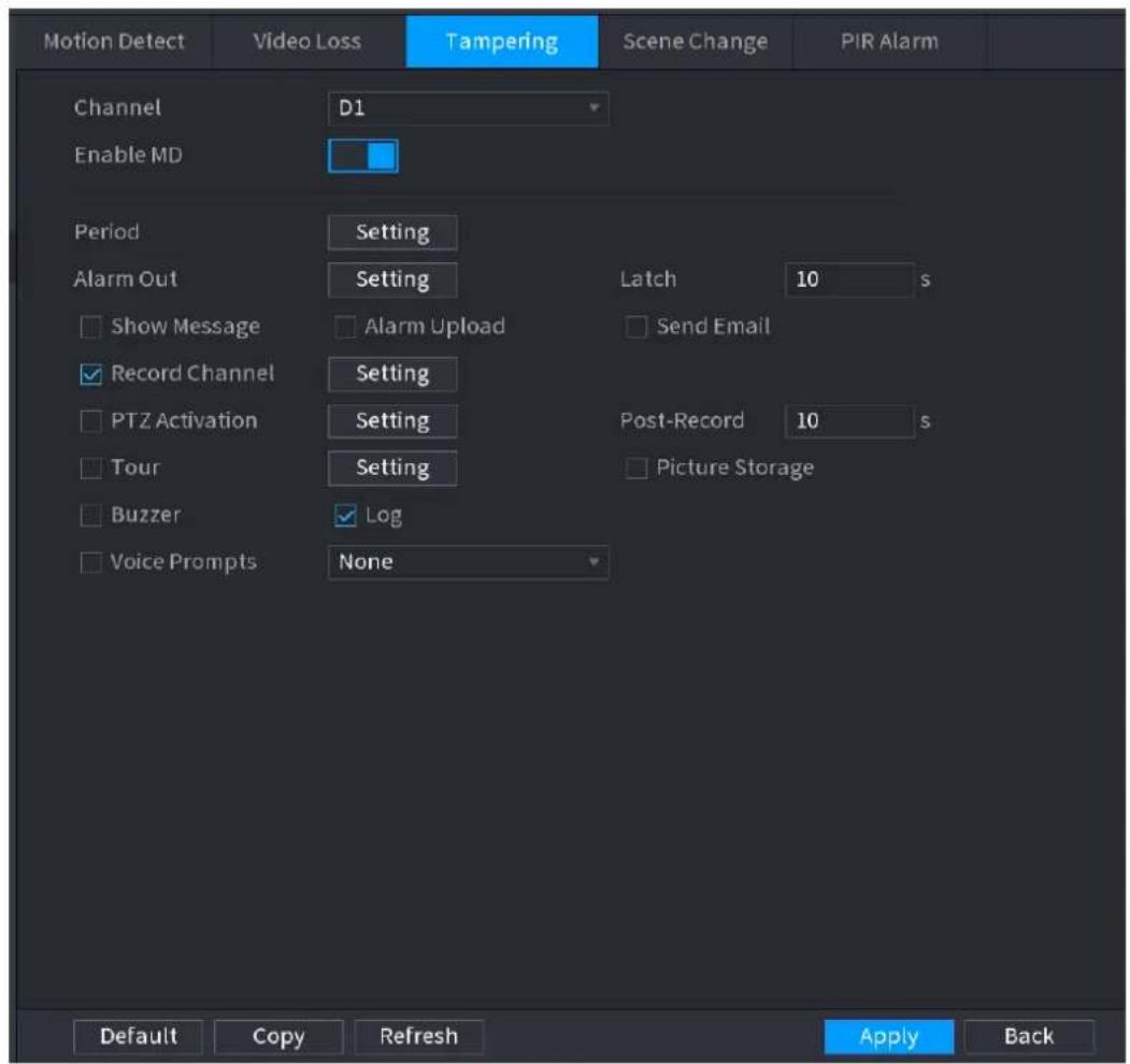
text_image
Motion Detect Video Loss Tampering Scene Change PIR Alarm Channel D1 Enable MD Period Setting Alarm Out Setting Latch 10 s Show Message Alarm Upload Send Email Record Channel Setting PTZ Activation Setting Post-Record 10 s Tour Setting Picture Storage Buzzer Log Voice Prompts None Default Copy Refresh Apply BackStep 2 To configure the settings for the tampering detection parameters, see "4.8.5.1 Motion Detect."
The Tampering function does not have region and sensitivity items.
Step 3 Click Apply to complete the settings.

- Click Default to restore the default setting.
- Click Copy, in the Copy dialog box, select the additional channel(s) that you want to copy the motion detection settings to, and then click Apply.
4.8.5.3 Video Loss
When the video loss occurs, the system activates the alarm.
Step 1 Select Main Menu > ALARM > VIDIEO DETECTION > Video Loss. The Video Loss interface is displayed. See Figure 4-172.
Figure 4-172
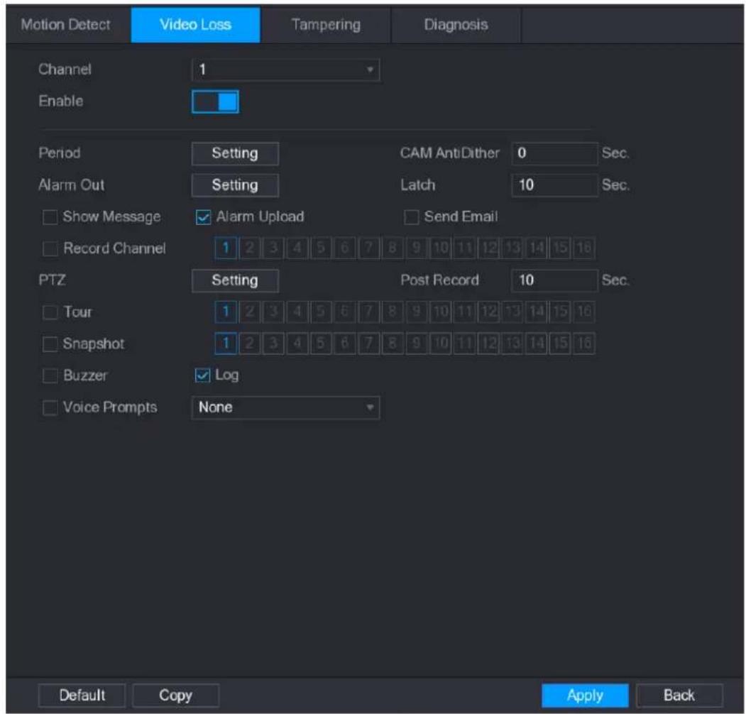
text_image
Motion Detect Video Loss Tampering Diagnosis Channel 1 Enable Period Setting CAM AntiDither 0 Sec. Alarm Out Setting Latch 10 Sec. Show Message ✓ Alarm Upload Send Email Record Channel 1 2 3 4 5 6 7 8 9 10 11 12 13 14 15 16 PTZ Setting Post Record 10 Sec. Tour 1 2 3 4 5 6 7 8 9 10 11 12 13 14 15 16 Snapshot 1 2 3 4 5 6 7 8 9 10 11 12 13 14 15 16 Buzzer ✓ Log Voice Prompts None Default Copy Apply BackStep 2 To configure the settings for the video loss detection parameters, see "4.8.5.1 Motion Detect."
The video loss function does not have region and sensitivity items.
Step 3 Click Apply to complete the settings.

- Click Default to restore the default setting.
- Click Copy, in the Copy dialog box, select the additional channel(s) that you want to copy the motion detection settings to, and then click Apply.
4.8.5.4 Scene Change
When the detected scene has changed, system can generate an alarm.
Step 1 Select Main Menu>ALARM>VIDEO DETECTION>SCENE CHANGE, The Scene Change interface is displayed. See Figure 4-173.
Figure 4-173
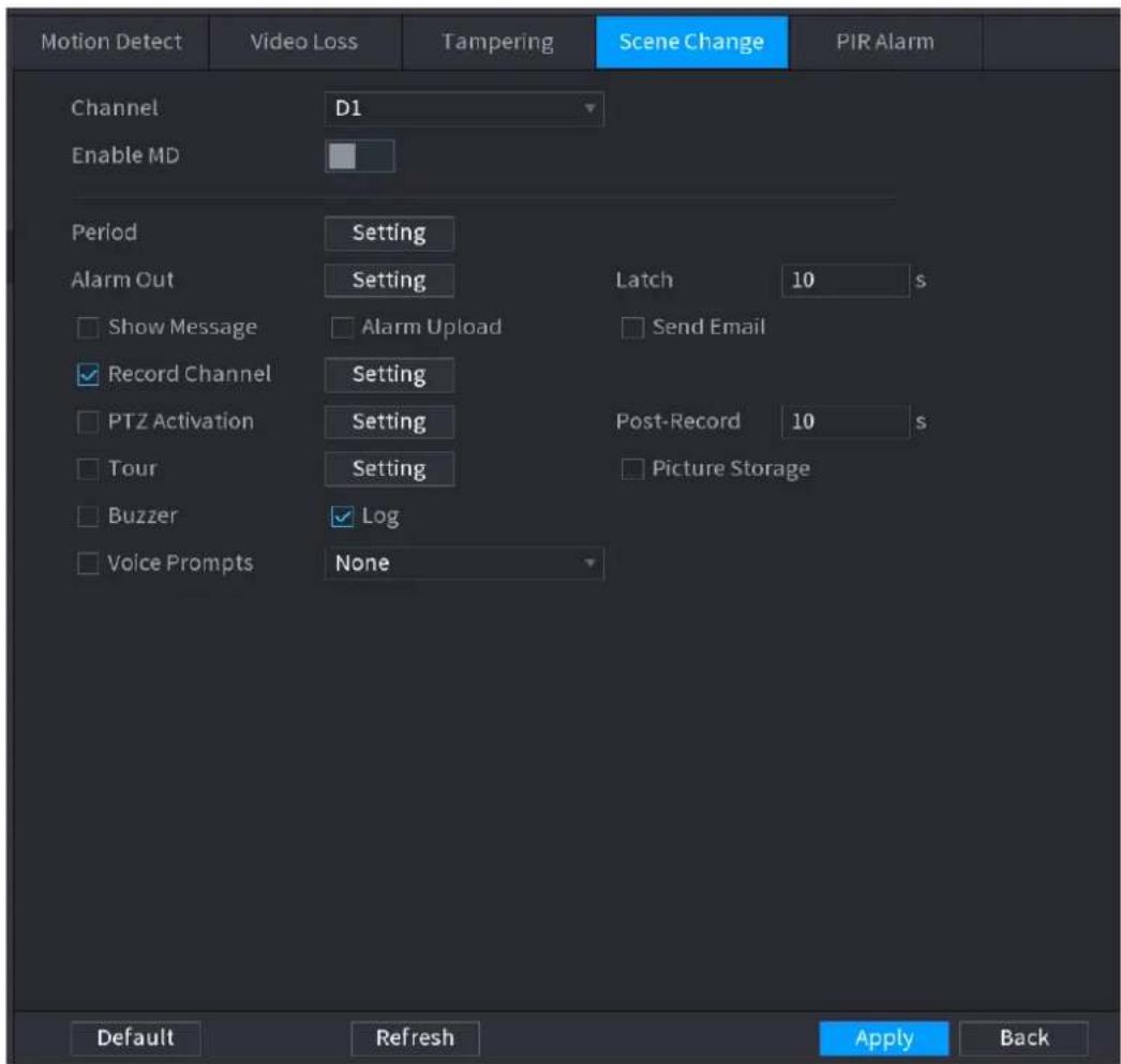
text_image
Motion Detect Video Loss Tampering Scene Change PIR Alarm Channel D1 Enable MD Period Setting Alarm Out Setting Latch 10 s Show Message Alarm Upload Send Email Record Channel Setting PTZ Activation Setting Post-Record 10 s Tour Setting Picture Storage Buzzer Log Voice Prompts None Default Refresh Apply BackStep 2 To configure the settings for the scene change parameters, see "4.8.5.1 Motion Detect." The scene change function does not have region and sensitivity items.
Step 3 Click Apply to complete the settings.

- Click Default to restore the default setting.
- Click Copy, in the Copy dialog box, select the additional channel(s) that you want to copy the motion detection settings to, and then click Apply.
4.8.5.5 PIR Alarm
When the detected scene has changed, system can generate an alarm.
PIR function helps enhancing the accuracy and validity of motion detect. It can filter the meaningless alarms that are activated by the objects such as falling leaves, flies. The detection range by PIR is smaller than the field angle.
PIR function is enabled by default if it is supported by the cameras. Enabling PIR function will get the motion detect to be enabled automatically to generate motion detection alarms; if the PIR function is not enabled, the motion detect just has the general effect.
Step 1 Select Main Menu > ALARM > VIDEO DETECT > PIR ALARM.
The PIR Alarm interface is displayed. See Figure 4-174.
Figure 4-174

text_image
Motion Detect Video Loss Tampering Scene Change PIR Alarm Channel D1 Region Setting Enable MD Period Setting Anti-Dither 0 s Alarm Out Setting Latch 0 s Alarm Upload Send Email Record Channel Setting Post-Record 10 s PTZ Activation Setting Tour Setting Picture Storage Buzzer Log Voice Prompts None Default Copy Refresh Apply BackStep 2 To configure the settings for the PIR alarm parameters, see "4.8.5.1 Motion Detect."
Step 3 Click Apply to complete the settings.

- Click Default to restore the default setting.
- Click Copy, in the Copy dialog box, select the additional channel(s) that you want to copy the motion detection settings to, and then click Apply.
4.8.6 Audio Detect
System can generate an alarm once it detect the audio is not clear, the tone color has changed or there is abnormal or audio volume changes.
Step 1 Select Main Menu > ALARM > AUDIO DETECT.
The AUDIO DETECT interface is displayed. See Figure 4-175.
Figure 4-175
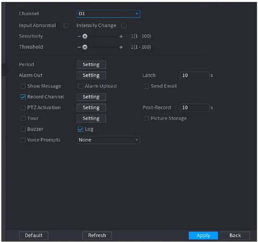
text_image
Channel D1 Input Abnormal Intensity Change Sensitivity - + 1(1 - 100) Threshold - + 1(1 - 100) Period Setting Alarm Out Setting Latch 10 s Show Message Alarm Upload Send Email Record Channel Setting PTZ Activation Setting Post-Record 10 s Tour Setting Picture Storage Buzzer Log Voice Prompts None Default Refresh Apply BackStep 2 Configure parameters. See Table 4-47.
Step 3 Click Apply to complete the settings.
Table 4-47
| Parameter | Description |
| Channel | In the Channel list, select a channel to set. |
| Input abnormal | Check the box here, system can generate an alarm once the audio input is abnormal. |
| Intensity change | Check the box here, system can generate an alarm once the audio volume becomes strong. |
| Period | Define a period during which the function is active. |
| Sensitivity | The higher the value is, the easier it is to trigger an alarm. But at the same time, the false alarm may occur. The default value is recommended. |
| Threshold | You can set intensity change threshold. The smaller the value is, the higher th sensitivity is. |
| Alarm Out | The alarm device (such as lights, sirens, etc.) is connected to the alarm output port. When an alarm occurs, the NVR device transmits the alarm information to the alarm device. |
| Latch | When the alarm ends, the alarm extended for a period of time. The time range is from 0 seconds to 300 seconds. |
| Show Message | Check box to enable a pop-up message in your local host PC. |
| Alarm Upload | Select the check box. When an alarm occurs, the NVR device uploads an alarm signal to the network (including the alarm center).This function is for some series products only.You need to set the alarm center first. For details, see "4.12.9 Alarm Centre." |
| Send Email | Select the check box. When an alarm occurs, the NVR device sends an email to the set mailbox to notify the user.You need to set the email first. For details, see "4.12.6 Email." |
| Record Channel | Select the check box and select the needed recording channel (support multiple choices). When an alarm occurs, the NVR device activates the channel for recording.You need to enable intelligent recording and auto recording first. For details, see "4.1.4.6 Schedule." |
| PTZ Activation | Select the check box and clickSettingto select the channel and PTZ action. When an alarm occurs, the NVR device associates the channel to perform the corresponding PTZ action. For example, activate the PTZ in channel one to turn to the preset point X.Tripwire alarm supports to activate PTZ preset point only.You need to set the corresponding PTZ actions first, see "4.4.3 Configuring PTZ Functions." |
| Delay | At the end of the alarm, the recording extends for a period of time. The time range is from 10 seconds to 300 seconds. |
| Tour | Select the check box and select the channel for tour. When an alarm occurs, the local interface of the NVR device displays the selected channel screen.You need to set the time interval and mode for tour first, see "4.16.2 Tour."After the tour is over, the preview interface is restored to the screen split mode before the tour. |
| Snapshot | Select theSnapshotcheck box to take a snapshot of the selected channel.To use this function, selectMain Menu>CAMERA>ENCODE>Snapshot, in the Mode list, select Event (Trigger). |
| Log | Select the check box, the NVR device records the alarm information in the log when an alarm occurs. |
| VoicePrompts | Check the box and then select the corresponding audio file from the dropdown list. System plays the audio file when the alarm occurs.[IMAGE]Refer to "4.17.1 File Manage" to add audio file first. |
| Buzzer | Select the check box to activate the buzzer when an alarm occurs. |
4.8.7 Thermal Alarm
System supports thermal devices and receives the alarm signal from it. It can recognize the alarm type, and then trigger the corresponding alarm actions.
The system supports fire alarm, temperature (temperature difference) and cold/hot alarm.
- Fire alarm: System generates an alarm once it detects there is a fire. The alarm mode includes Preset and Excluded zone.
- Temperature (temperature difference): System triggers an alarm once the temperature difference between two positions is higher or below the specified threshold.
- Clod/hot alarm: System triggers an alarm once the detected position temperature is higher or below the specified threshold.

- The connected channel shall support temperature test function.
- This function is for some series products only. It supports enable/disable function only. Go to the front-end device to set corresponding parameters.
Step 1 Select Main Menu > ALARM > THERMAL ALARM.
The THERMAL ALARM interface is displayed. See Figure 4-176.
Figure 4-176
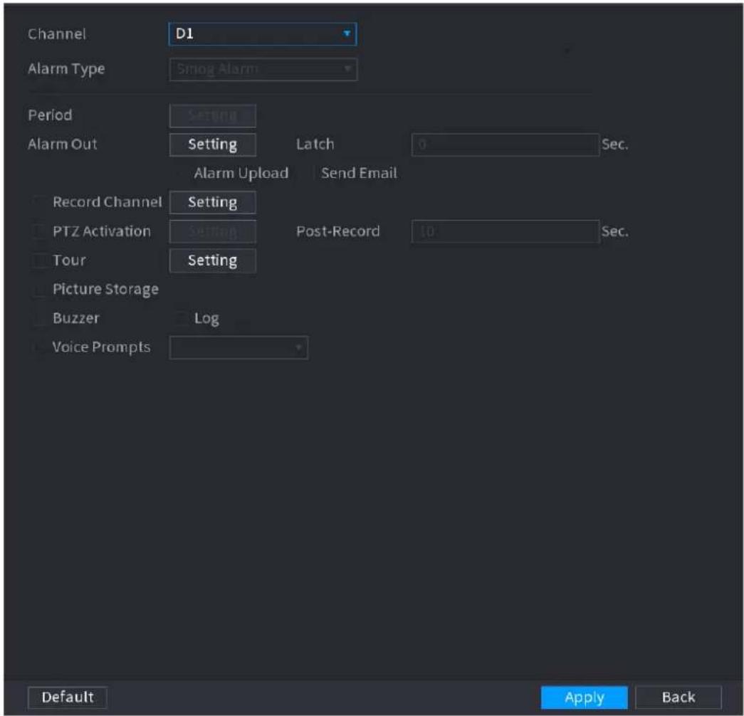
text_image
Channel D1 Alarm Type Smog Alarm Period Setting Alarm Out Setting Latch 0 Sec. Alarm Upload Send Email Record Channel Setting PTZ Activation Setting Post-Record 10 Sec. Tour Setting Picture Storage Buzzer Log Voice Prompts Default Apply BackStep 2 Select a channel and alarm type, enable the thermal alarm function.
Step 3 Select fire mode and then enable this function (If the alarm type is Fire Alarm). System supports preset mode and zone excluded mode.
- Preset: Select a preset and then enable the function. System generates an alarm once it detect there is a fire.
- Global: System filters the specified high temperature zone. System generates an alarm once the rest zone has fire.
Step 4 Set parameters. See Table 4-48.
Step 5 Click Apply.
Table 4-48
| Parameter | Description |
| Alarm Out | The alarm device (such as lights, sirens, etc.) is connected to the alarm output port. When an alarm occurs, the NVR device transmits the alarm information to the alarm device. |
| Latch | When the alarm ends, the alarm extended for a period of time. The time range is from 0 seconds to 300 seconds. |
| Show Message | Check box to enable a pop-up message in your local host PC. |
| AlarmUpload | Select the check box. When an alarm occurs, the NVR device uploads an alarm signal to the network (including the alarm center).This function is for some series products only.You need to set the alarm center first. For details, see "4.12.9 Alarm Centre." |
| Send Email | Select the check box. When an alarm occurs, the NVR device sends an email to the set mailbox to notify the user.You need to set the email first. For details, see "4.12.6 Email." |
| Record Channel | Select the check box and select the needed recording channel (support multiple choices). When an alarm occurs, the NVR device activates the channel for recording.You need to enable intelligent recording and auto recording first. For details, see "4.1.4.6 Schedule." |
| PTZ Activation | Select the check box and clickSettingto select the channel and PTZ action. When an alarm occurs, the NVR device associates the channel to perform the corresponding PTZ action. For example, activate the PTZ in channel one to turn to the preset point X.Tripwire alarm supports to activate PTZ preset point only.You need to set the corresponding PTZ actions first, see "4.4.3 Configuring PTZ Functions." |
| Delay | At the end of the alarm, the recording extends for a period of time. The time range is from 10 seconds to 300 seconds. |
| Tour | Select the check box and select the channel for tour. When an alarm occurs, the local interface of the NVR device displays the selected channel screen.You need to set the time interval and mode for tour first, see "4.16.2 Tour."After the tour is over, the preview interface is restored to the screen split mode before the tour. |
| Snapshot | Select theSnapshotcheck box to take a snapshot of the selected channel.To use this function, selectMain Menu>CAMERA>ENCODE>Snapshot, in the Mode list, select Event (Trigger). |
| Log | Select the check box, the NVR device records the alarm information in the log when an alarm occurs. |
| VoicePrompts | Check the box and then select the corresponding audio file from the dropdown list. System plays the audio file when the alarm occurs.[IMAGE]Refer to "4.17.1 File Manage" to add audio file first. |
| Buzzer | Select the check box to activate the buzzer when an alarm occurs. |
4.8.8 Abnormality
Step 1 Select Main Menu>ALARM>ABNORMALITY.
The Abnormality interface is displayed. See Figure 4-177.
Figure 4-177
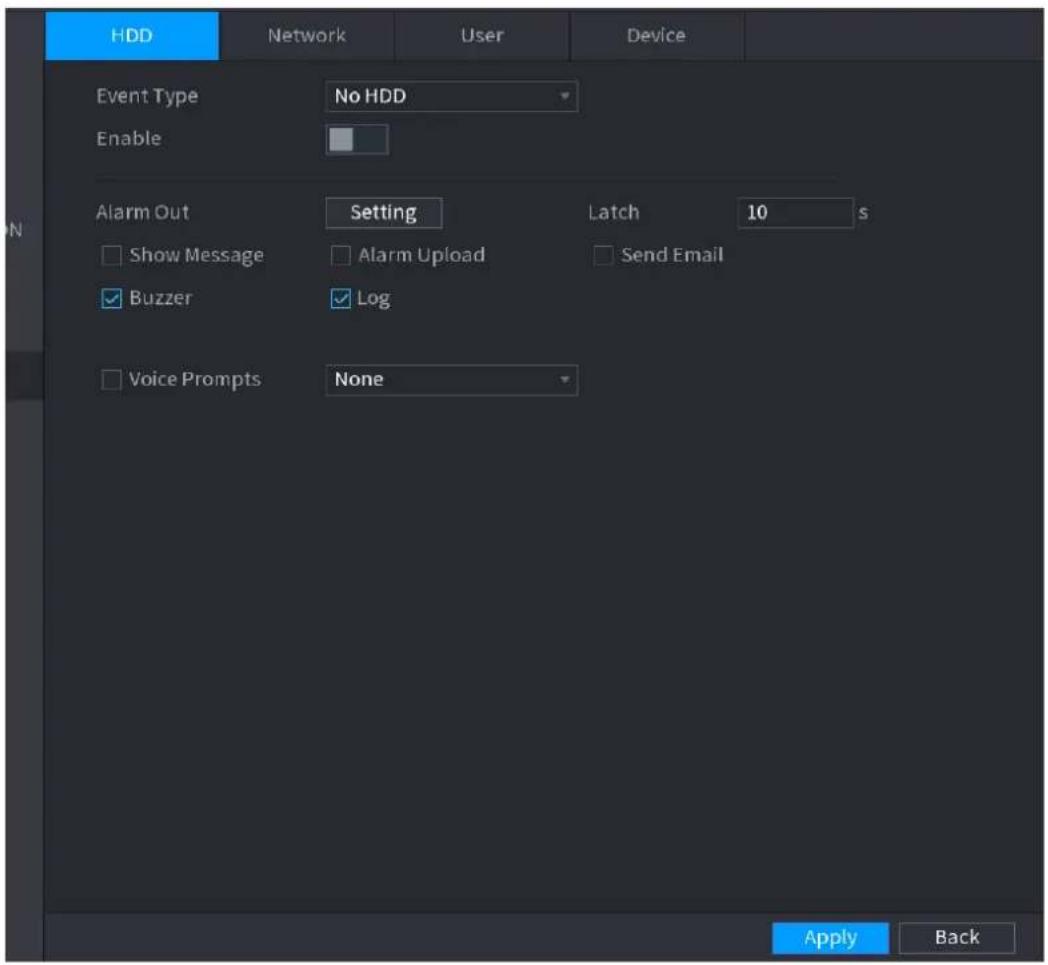
text_image
HDD Network User Device Event Type No HDD Enable Alarm Out Setting Latch 10 s Show Message Alarm Upload Send Email Buzzer Log Voice Prompts None Apply BackFigure 4-178
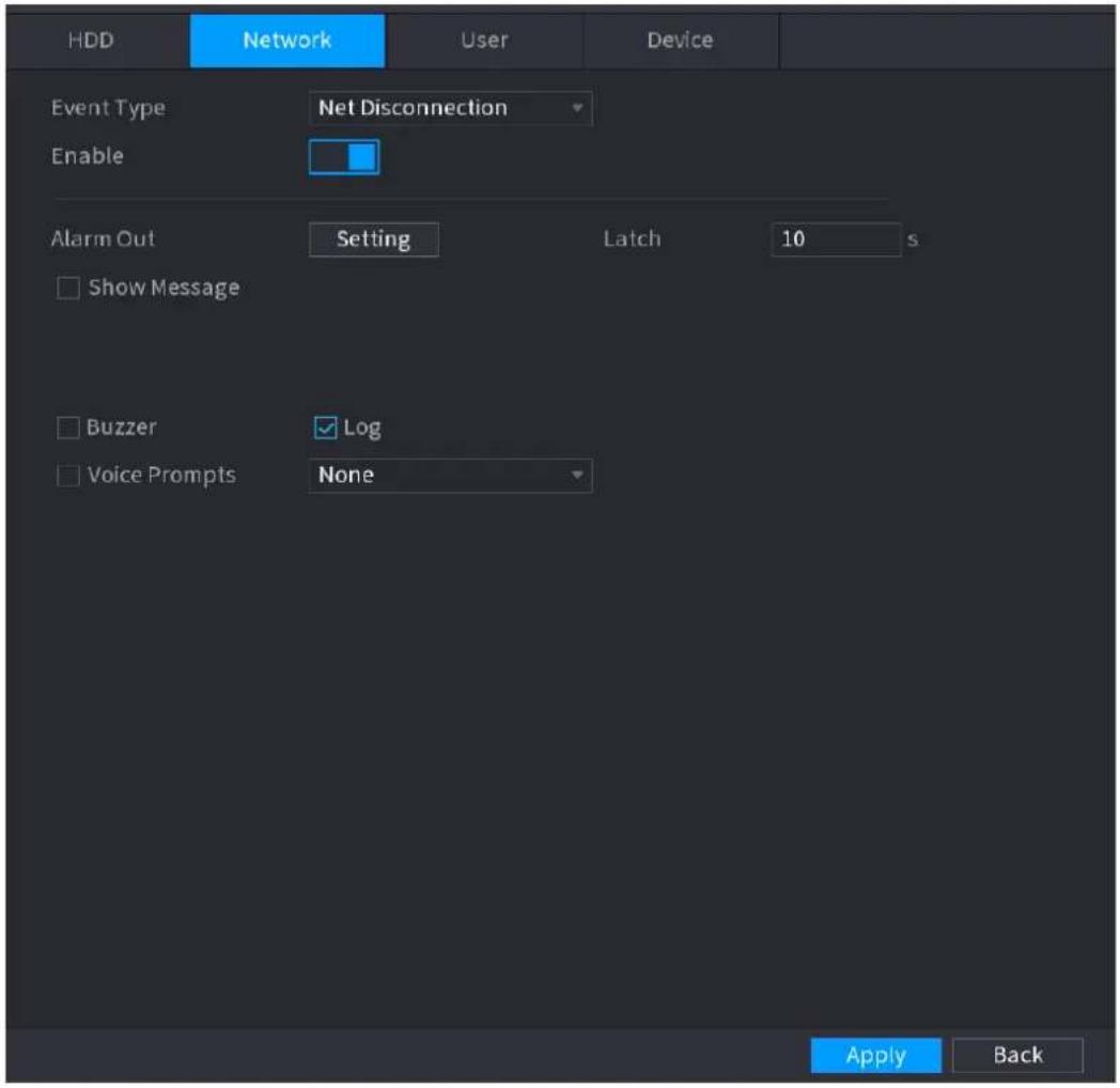
text_image
HDD Network User Device Event Type Net Disconnection Enable Alarm Out Setting Latch 10 s Show Message Buzzer Log Voice Prompts None Apply BackFigure 4-179
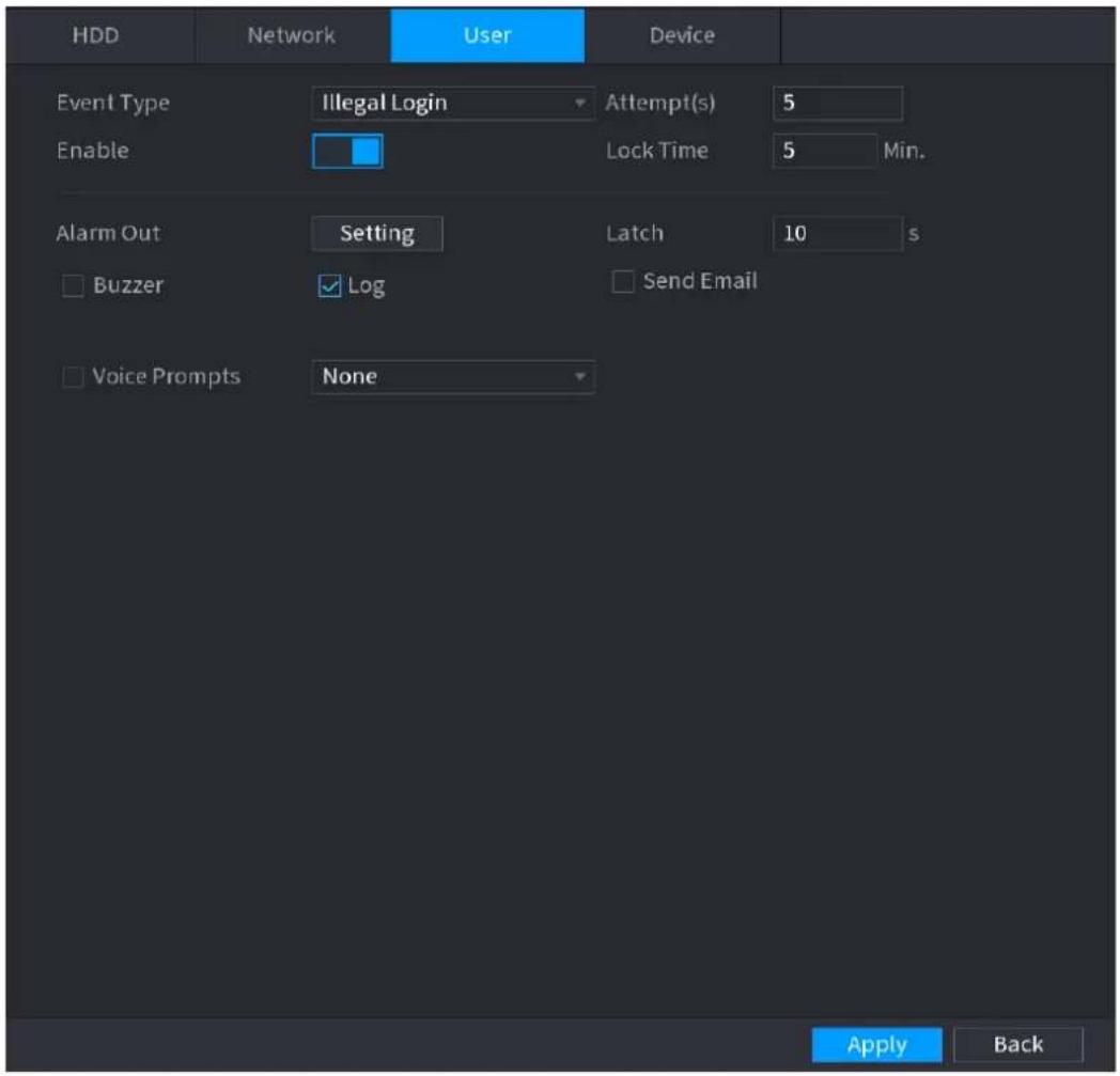
text_image
HDD Network User Device Event Type Illegal Login Attempt(s) 5 Enable Lock Time 5 Min. Alarm Out Setting Latch 10 s Buzzer Log Send Email Voice Prompts None Apply BackFigure 4-180
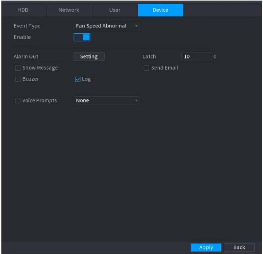
text_image
HDD Network User Device Event Type Fan Speed Abnormal Enable Alarm Out Setting Latch 10 s Show Message Send Email Buzzer Log Voice Prompts None Apply BackStep 2 Configure parameters. See Table 4-49.
Step 3 Click Apply.
Table 4-49
| Parameter | Description |
| Event Type | Click the corresponding tab to set different abnormality events.HDD: Sets process method when there is a HDD event such as HDD error, no HDD, no space. See Figure 4-177.Network: Sets process method when there is a network event such as disconnection, IP conflict, MAC conflict. See Figure 4-178.User: Sets process method when there is an Illegal login event. See Figure 4-179.Device: Sets process method when fan speed is abnormal, or there is a network security event. See Figure 4-180.Different series products support different event types. The actual product shall prevail. |
| Enable | Check the box to enable the function, |
| Less than | System generates an alarm once the HDD space is less than the threshold.For HDD Spacetype only. |
| Attempts | Set the maximum number of allowable wrong password entries. The account will be locked after your entries exceed the maximum numberFor Illegal Login type only. |
| Lock Time | Set how long the account is locked for. The value ranges from 1 minute to 60 minutes.For Illegal Login type only. |
| Alarm Out | The alarm device (such as lights, sirens, etc.) is connected to the alarm output port. When an alarm occurs, the NVR device transmits the alarm information to the alarm device. |
| Latch | When the alarm ends, the alarm extended for a period of time. The time range is from 0 seconds to 300 seconds. |
| Show Message | Check box to enable a pop-up message in your local host PC. |
| Alarm Upload | Select the check box. When an alarm occurs, the NVR device uploads an alarm signal to the network (including the alarm center).This function is for some series products only.You need to set the alarm center first. For details, see "4.12.9 Alarm Centre." |
| Send Email | Select the check box. When an alarm occurs, the NVR device sends an email to the set mailbox to notify the user.You need to set the email first. For details, see "4.12.6 Email." |
| Record Channel | Select the check box and select the needed recording channel (support multiple choices). When an alarm occurs, the NVR device activates the channel fo recording.You need to enable intelligent recording and auto recording first. For details, see "4.1.4.6 Schedule." |
| PTZ Activation | Select the check box and clickSettingto select the channel and PTZ action. When an alarm occurs, the NVR device associates the channel to perform the corresponding PTZ action. For example, activate the PTZ in channel one to turn to the preset point X.Tripwire alarm supports to activate PTZ preset point only.You need to set the corresponding PTZ actions first, see "4.4.3 Configuring PTZ Functions." |
| Delay | At the end of the alarm, the recording extends for a period of time. The time range is from 10 seconds to 300 seconds. |
| Tour | Select the check box and select the channel for tour. When an alarm occurs, the local interface of the NVR device displays the selected channel screen. You need to set the time interval and mode for tour first, see "4.16.2 Tour."After the tour is over, the preview interface is restored to the screen split mode before the tour. You need to set the time interval and mode for tour first, see "4.16.2 Tour."After the tour is over, the preview interface is restored to the screen split mode before the tour. |
| Snapshot | Select the Snapshot check box to take a snapshot of the selected channel.To use this function, select Main Menu > CAMERA > ENCODE > Snapshot, in the Mode list, select Event (Trigger). |
| Log | Select the check box, the NVR device records the alarm information in the log when an alarm occurs. |
| VoicePrompts | Check the box and then select the corresponding audio file from the dropdown list. System plays the audio file when the alarm occurs.Refer to "4.17.1 File Manage" to add audio file first. |
| Buzzer | Select the check box to activate the buzzer when an alarm occurs. |
4.9 POS
You can connect the Device to the POS (Point of Sale) machine and receive the information from it. This function applies to the scenarios such as supermarket POS machine. After connection is established, the Device can access the POS information and display the overlaid text in the channel window.

Playing POS information in the local playback and viewing the POS information in the live view screen support single-channel mode and four-channel mode. Displaying monitoring screen and playing back in the web support multi-channel mode.
4.9.1 Search

The system supports fuzzy search.
Step 1 Select Main Menu > POS > POS SEARCH.
The POS SEARCH interface is displayed. See Figure 4-181.
Figure 4-181
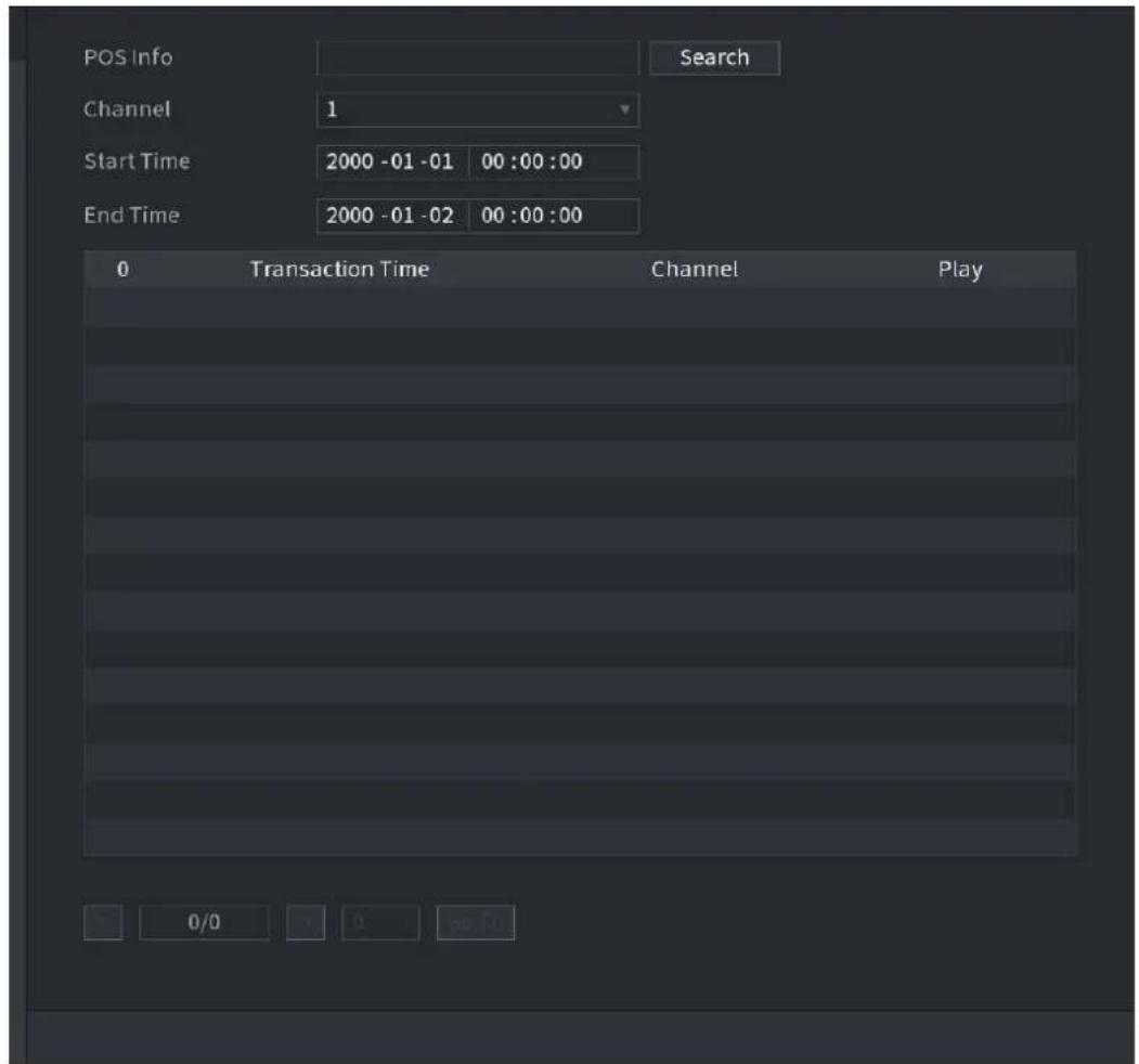
text_image
POS Info Search Channel 1 Start Time 2000 -01 -01 00:00:00 End Time 2000 -01 -02 00:00:00 0 Transaction Time Channel Play 0/0 0 50:10Step 2 In the POS SEARCH box, enter the information such as transaction number on your receipt, amount, or product name.
Step 4 In the Start Time box and End Time box, enter the time period that you want to search the POS transaction information.
Step 5 Click Search. The searched transaction results display in the table.
4.9.2 Settings
Step 1 Select Main Menu > POS > POS SETUP. The POS SETUP interface is displayed. See Figure 4-182.
Figure 4-182
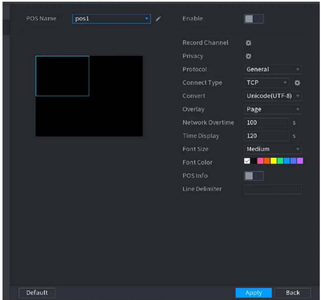
text_image
POS Name pos1 Enable Record Channel Privacy Protocol General Connect Type TCP Convert Unicode(UTF-8) Overlay Page Network Overtime 100 s Time Display 120 s Font Size Medium Font Color POS Info Line Delimiter Default Apply BackStep 2 Configure the settings for the POS parameters. See Table 4-50.
Step 3 Click Apply to complete the settings.
4.9.2.1 Privacy Setup
Table 4-50
Step 1 Click Setup
| Parameter | Description |
| POS Name | In the POS Name list, select the POS machine that you want to  igures settings for. Click to modify the POS name.The POS name shall be unique.The POS name supports 21 Chinese characters or 63 English characters. igures settings for. Click to modify the POS name.The POS name shall be unique.The POS name supports 21 Chinese characters or 63 English characters. |
| Enable | Enable the POS function. |
| Record CH | Click  select a channel to record. select a channel to record. |
| Privacy Setup | Enter the privacy contents. Refer to "4.9.2.1 Privacy Setup". |
| Protocol Type | Select POS by default. Different machine corresponds to different protocol. |
| Connect Type | In the Connect Type list, select the connection protocol type.Click in the IP Address interface is displayed.In the Source IP box, enter the IP address (the machine that is connected to the Device) that sends messages. |
| Convert | Select a character encoding mode. |
| Overlay | In the Overlay list, Select Turn or ROLL.Turn: Once the information is at 16 lines, system displays the next page.ROLL: Once the information is at 16 lines, system rolls one line after another to delete the first line.When the local preview mode is in 4-split, the turn/ROLL function is based on 8 lines. |
| Network time out | When the network is not working correctly and cannot be recovered after the entered timeout limit, the POS information will not display normally. After the network is recovered, the latest POS information will be displayed. |
| Time Display | Enter the time that how long you want to keep the POS information displaying. For example, enter 5, the POS information disappear from the screen after 5 seconds. |
| Font Size | In the Font Size list, select Small, Medium, or Big as the text size of POS information |
| COLOR | In the color bar, click to select the color for the text size of POS information. |
| POS Info | Enable the POS Info function, the POS information displays in the live view/WEB. |
| Line Delimiter | There is no line delimiter by default.After set the line delimiter (HEX), the overlay information after the delimiter is displayed in the new line. For example, the line delimiter is F and the overlay information is 123156789, NVR displays overlay information on the local preview interface and Web as:1236789 |
The Privacy interface is displayed. See Figure 4-183.
Figure 4-183
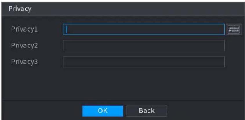
text_image
Privacy Privacy1 Privacy2 Privacy3 OK BackStep 2 Set privacy information.
Step 3 Click OK button.
4.9.2.2 Connection type
- Connection type is UDP or TCP.
Step 1 Select Connect Type as UDP, TCP_CLINET or TCP.
Step 2 Click

The IP Address interface is displayed. See Figure 4-184.
Figure 4-184
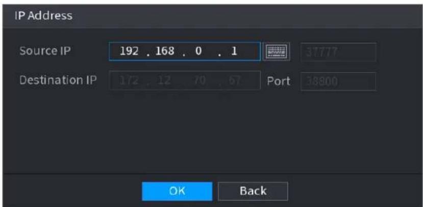
text_image
IP Address Source IP 192 . 168 . 0 . 1 37777 Destination IP 172 . 12 . 70 . 67 Port 38800 OK BackStep 3 Source IP and Port. Refers to POS IP address and port.
Step 4 Click OK to complete setup.
4.10 Operation and Maintenance
4.10.1 Log
You can view and search the log information, or backup log to the USB device.
Step 1 Select Main Menu > OPERATION > LOG.
The LOG interface is displayed. See Figure 4-185.
Figure 4-185
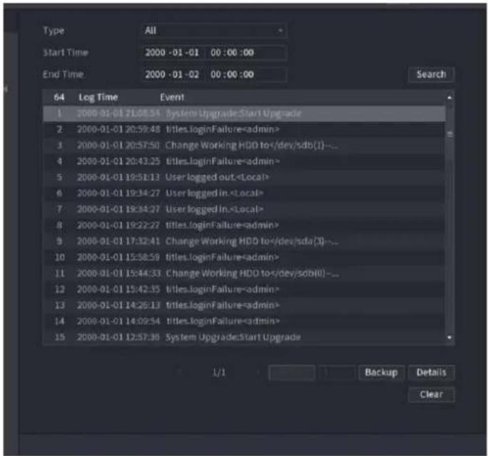
text_image
Type All Start Time 2000 -01 -01 00 :00 :00 End Time 2000 -01 -02 00 :00 :00 Search 64 Log Time Event 1 2000-01-01 71:08:54 System Upgrade:Start Upgrade 2 2000-01-01 20:59:48 titles.loginFailureStep 5 In the Type list, select the log type that you want to view (System, Config, Storage, Record, Account, Clear, Playback, and Connection) or select All to view all logs.
Step 6 In the Start Time box and End Time box, enter the time period to search, and then click Search.
The search results are displayed. See Figure 4-186.
Figure 4-186
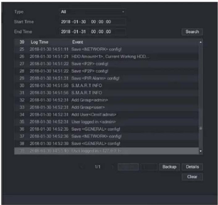
text_image
Type All Start Time 2018-01-30 00:00:00 End Time 2018-01-31 00:00:00 39 Log Time Event 25 2018-01-30 14:51:11 Save
- Click Details or double-click the log that you want to view, the Detailed Information interface is displayed. Click Next or Previous to view more log information.
- Click Backup to back up the logs into the USB storage device.
- Click Clear to remove all logs.
4.10.2 System
4.10.2.1 Version
Select Main Menu > SYSTEM > VERSION, you can go to VERSION interface.
You can view NVR version information. Slight different may be found on the user interface.
4.10.2.2 HDD Info
You can view the HDD quantity, HDD type, total space, free space, status, and S.M.A.R.T information.
Select Main Menu > OPERATION > INFOMATION > HDD, the HDD interface is displayed. See Figure 4-187. Refer to Table 4-51 for detailed information.
Figure 4-187
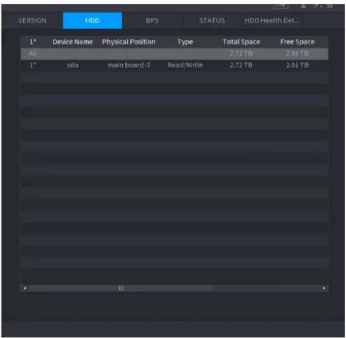
text_image
VERSION HDD BPS STATUS HDD Health Det... 1* Device Name Physical Position Type Total Space Free Space All 2.72 TB 2.01 TB 1* sda main board-3 Read/Write 2.72 TB 2.01 TBTable 4-51
| Parameter | Description |
| No. | Indicates the number of the currently connected HDD. The asterisk (*) means the current working HDD. |
| Device Name | Indicates name of HDD. |
| Physical Position | Indicates installation position of HDD. |
| Type | Indicates HDD type. |
| Total Space | ● Indicates the total capacity of HDD. |
| Free Space | Indicates the usable capacity of HDD. |
| Status | Indicates the status of the HDD to show if it is working normally. |
| S.M.A.R.T | View the S.M.A.R.T reports from HDD detecting. |
4.10.2.3 BPS
Here is for you to view current video bit rate (kb/s) and resolution.
Select Main Menu > OPERATION > INFOMATION > BPS, the BPS interface is displayed. See Figure 4-188.
Figure 4-188
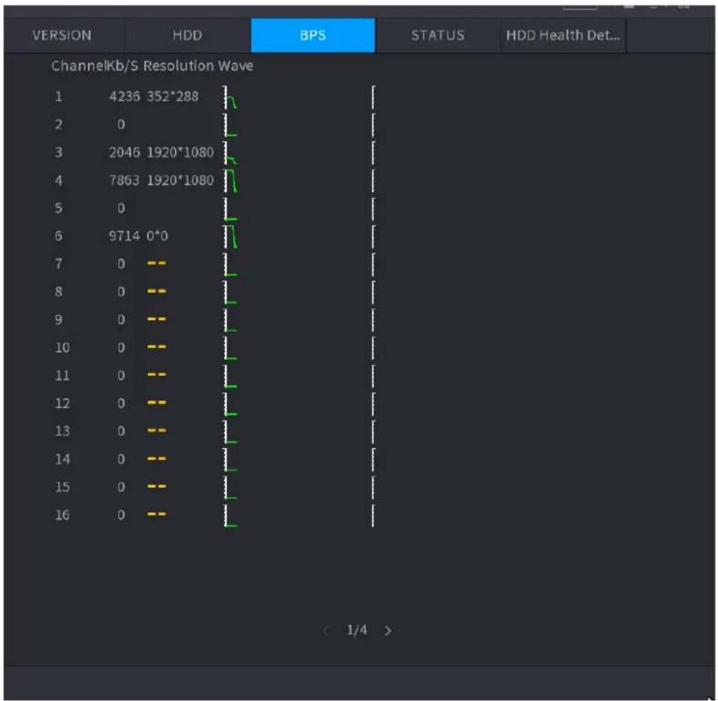
line
| VERSION | HDD | BPS | |--------|---------|---------| | 1 | 4236 | | | 2 | 0 | | | 3 | 2046 | | | 4 | 7863 | | | 5 | 0 | | | 6 | 9714 | | | 7 | 0 | | | 8 | 0 | | | 9 | 0 | | | 10 | 0 | | | 11 | 0 | | | 12 | 0 | | | 13 | 0 | | | 14 | 0 | | | 15 | 0 | | | 16 | 0 | |4.10.2.4 Device Status
You can view fan running status such as speed, CPU temperature, and memory.
Select Main Menu > OPERATION > INFOMATION > Status, the Status interface is displayed. See Figure 4-189.
Figure 4-189
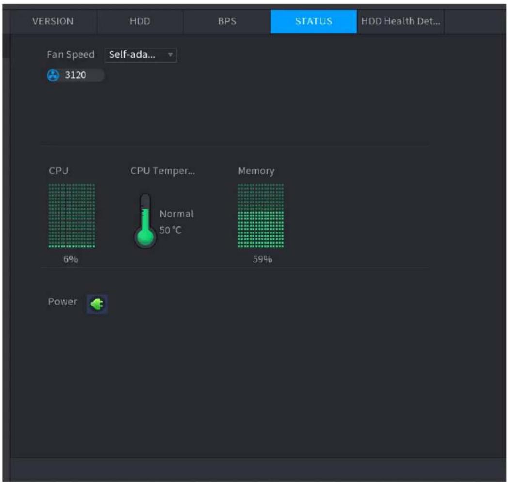
text_image
VERSION HDD BPS STATUS HDD Health Det... Fan Speed Self-ada... 3120 CPU CPU Temper... Normal 50 °C Memory 6% 59% Power4.10.2.5 HDD Health Detection
You can view HDD health status. System supports Seagate SKYHAWK series 4T and higher HDD. It displays HDD name, space, manufacturer, Serial No., and health status.
Step 1 Select Main Menu > OPERATION > INFOMATION > HDD Health Detection. The HDD Health Detection interface is displayed. See Figure 4-190.
Figure 4-190
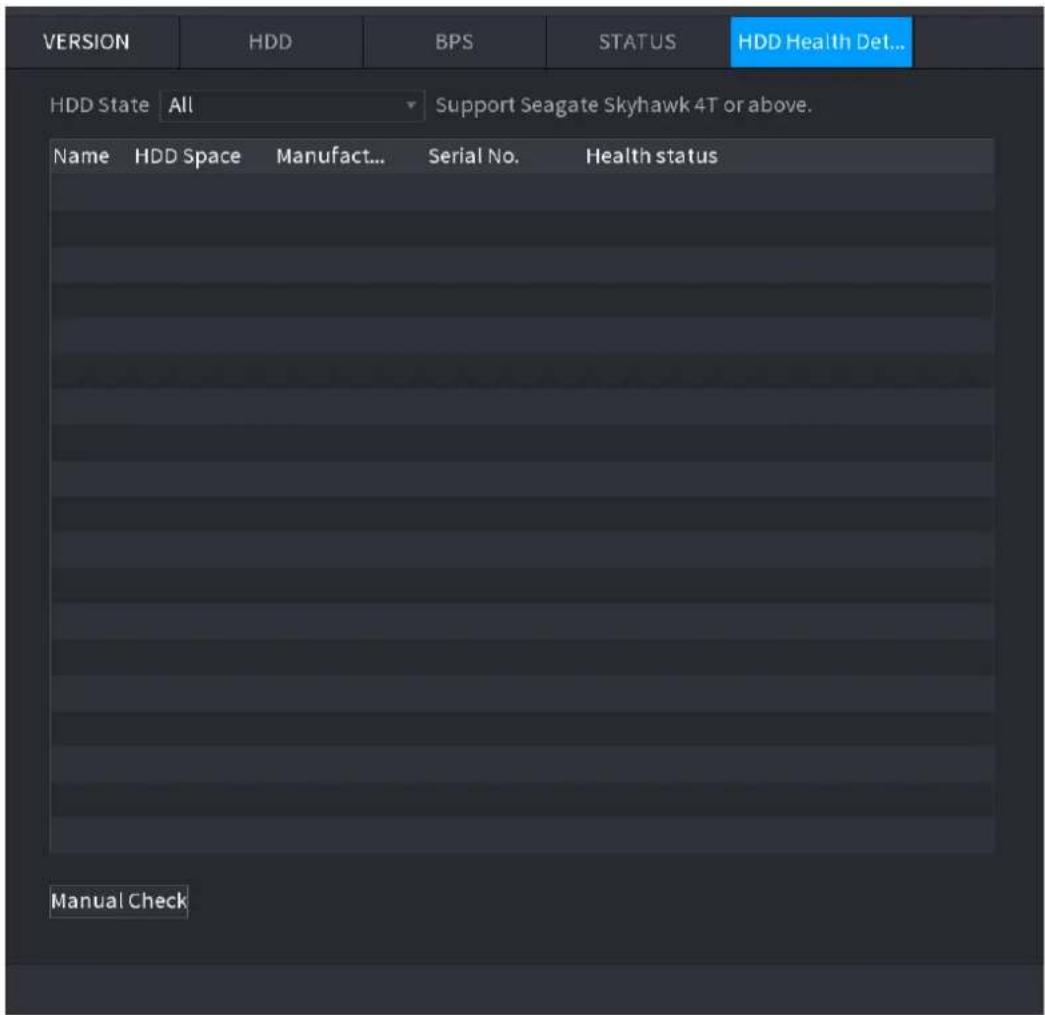
text_image
VERSION HDD BPS STATUS HDD Health Det... HDD State All Support Seagate Skyhawk 4T or above. Name HDD Space Manufact... Serial No. Health status Manual CheckStep 2 Double-click the HDD in the list, system displays the detection report.
Step 3 Select an item in the list, system displays the corresponding report. System displays the curve report of the recent week by default.
4.10.3 Network
4.10.3.1 Online User
You can view the online user information or block any user for a period of time. To block an
online user, click and then enter the time that you want to block this user. The maximum value you can set is 65535.
The system detects every 5 seconds to check whether there is any user added or deleted, and update the user list timely.
Select Main Menu > OPERATION > NETWORK > ONLINE USERS, the Online Users interface is displayed. See Figure 4-191.
Figure 4-191
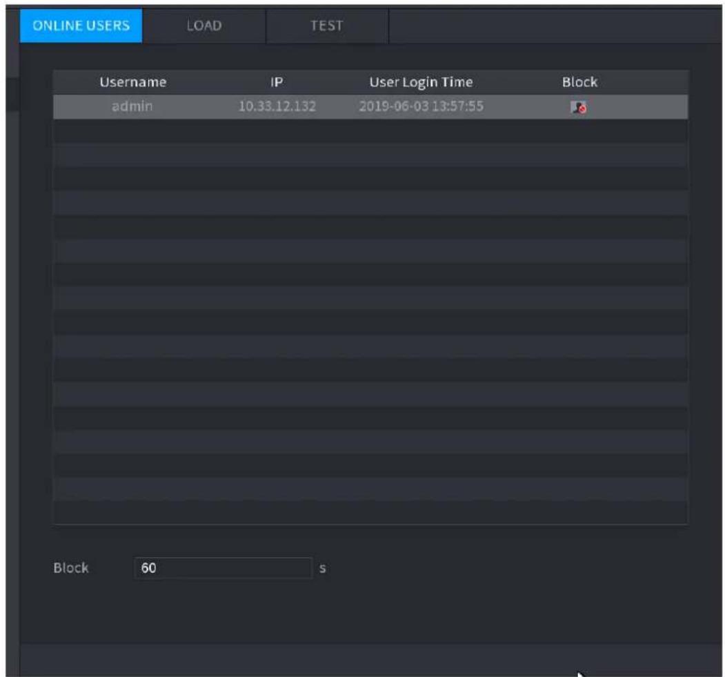
text_image
ONLINE USERS LOAD TEST Username IP User Login Time Block admin 10.33.12.132 2019-06-03 13:57:55 Block 60 s4.10.3.2 Network Load
Network load means the data flow which measures the transmission capability. You can view the information such as data receiving speed and sending speed.
Step 1 Select Main Menu > INFO > NETWORK > LOAD.
The LOAD interface is displayed. See Figure 4-192.
Figure 4-192
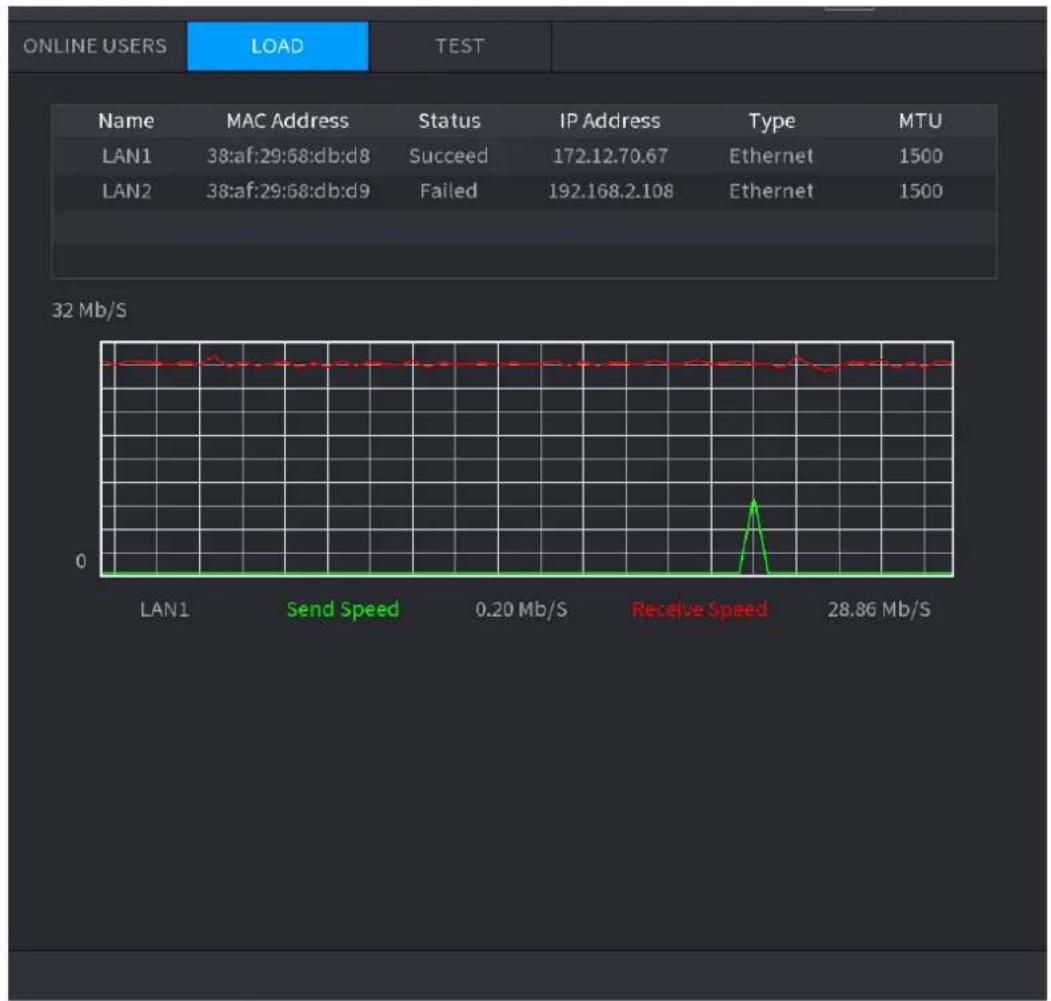
line
| MAC Address | Status | IP Address | Type | MTU | | ----------- | ------ | ---------- | ---- | --- | | LAN1 | Succeed | 172.12.70.67 | Ethernet | 1500 | | LAN2 | Failed | 192.168.2.108 | Ethernet | 1500 |Step 2 Click the LAN name that you want to view, for example, LAN1.
The system displays the information of data sending speed and receiving speed.

- System displays LAN1 load by default.
- Only one LAN load can be displayed at one time.
4.10.3.3 Network Test
You can test the network connection status between the Device and other devices.
Step 1 Select Main Menu > INFO > NETWORK > TEST.
The TEST interface is displayed. See Figure 4-193.
Figure 4-193
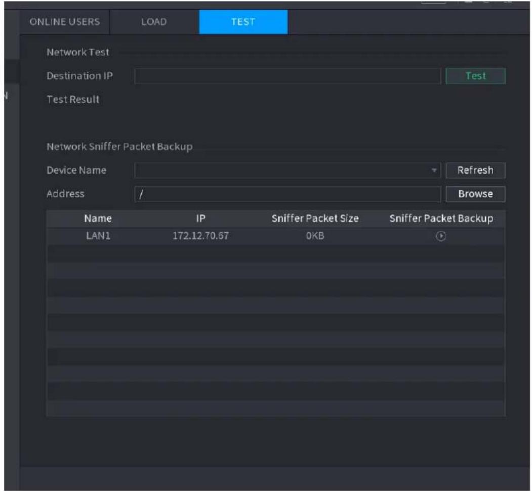
text_image
ONLINE USERS LOAD TEST Network Test Destination IP Test Test Result Network Sniffer Packet Backup Device Name Refresh Address / Browse Name IP Sniffer Packet Size Sniffer Packet Backup LAN1 172.12.70.67 0KBStep 2 In the Destination IP box, enter the IP address.
Step 3 Click Test.
After testing is completed, the test result is displayed. You can check the evaluation for average delay, packet loss, and network status.
4.10.4 Maintenance and Management
4.10.4.1 Device Maintenance
When the Device has been running for a long time, you can configure the auto reboot when the Device is not working. You can also configure the case fan mode to reduce noise and extend the service life.
Step 1 Select Main Menu > OPERATION > SYSTEM MAINTAIN > AUTO MAINTAIN.
The AUTO MAINTAIN interface is displayed. See Figure 4-194.
Figure 4-194
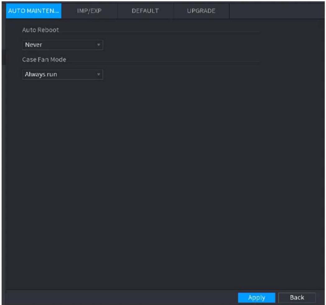
text_image
AUTO MAINTEN... IMP/EXP DEFAULT UPGRADE Auto Reboot Never Case Fan Mode Always run Apply BackStep 4 Configure the settings for the system maintenance parameters. See Table 4-52.
Table 4-52
| Parameter | Description |
| Auto Reboot | In theAuto Rebootlist, select the reboot time. |
| Case Fan Mode | In theCase Fan Modelist, you can selectAlways run or Auto. If you selectAuto, the case fan will stop or start according to the external conditions such as the Device temperature.This function is for some series products only., and it is only supported on the local configuration interface. |
Step 5 Click Apply to complete the settings.
4.10.4.2 IMP/EXP
You can export or import the Device system settings if there are several Devices that require the same setup.

- The IMP/EXP interface cannot be opened if the backup operation is ongoing on the other interfaces.
- When you open the IMP/EXP interface, the system refreshes the devices and sets the current directory as the first root directory.
- Click Format to format the USB storage device.
Exporting System Settings
Step 1 Select Main Menu > OPERATION > SYSTEM MAITAIN > IMP/EXP.
The IMP/EXP interface is displayed. See Figure 4-195.
Figure 4-195
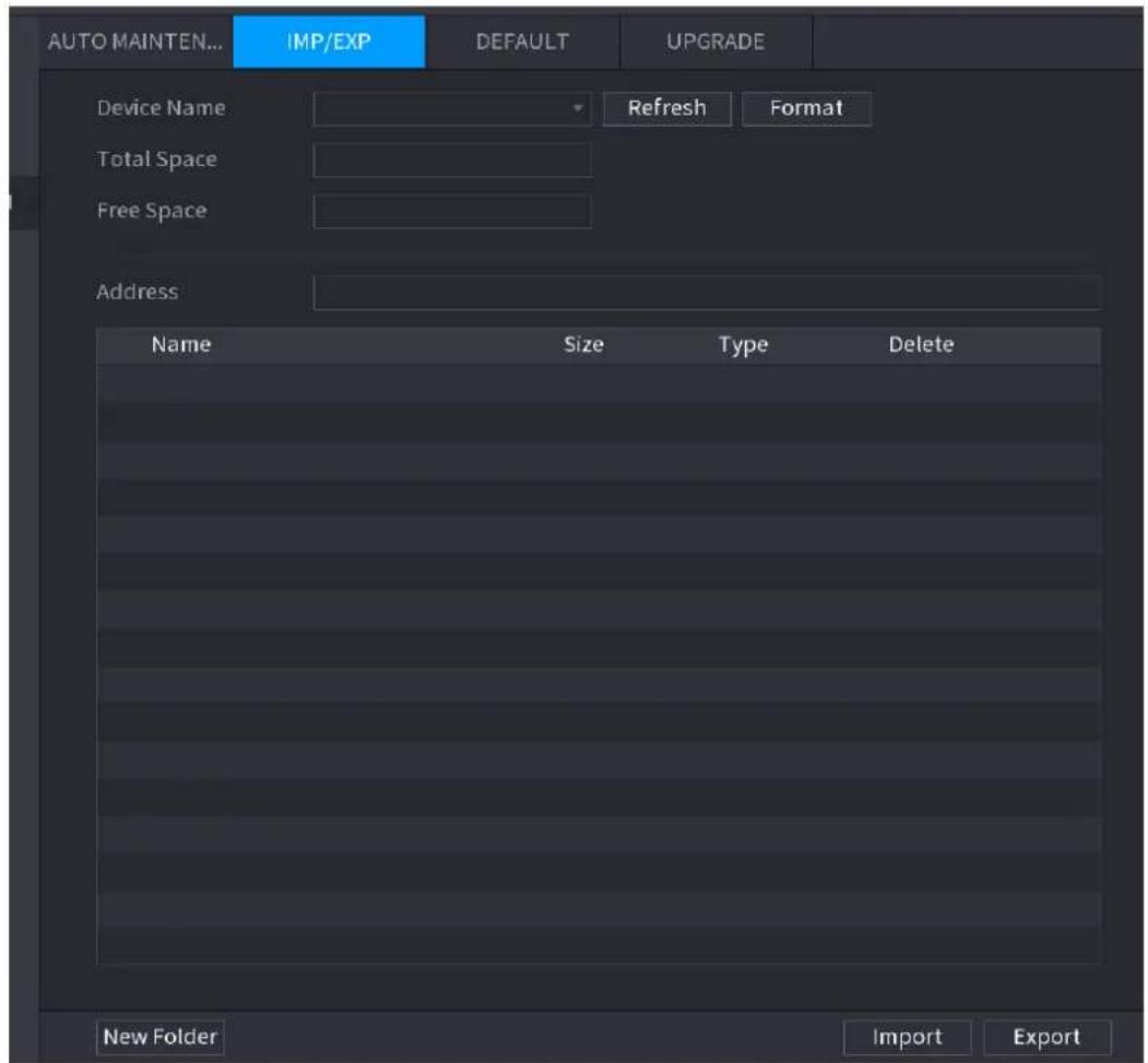
text_image
AUTO MAINTEN... IMP/EXP DEFAULT UPGRADE Device Name Refresh Format Total Space Free Space Address Name Size Type Delete New Folder Import ExportStep 2 Insert a USB storage device into one of the USB ports on the Device.
Step 3 Click Refresh to refresh the interface.
The connected USB storage device is displayed. See Figure 4-196.
Figure 4-196
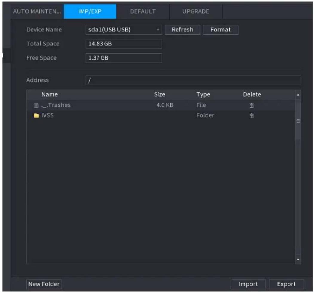
text_image
AUTO MAINTEN... IMP/EXP DEFAULT UPGRADE Device Name sda1(USB USB) Refresh Format Total Space 14.83 GB Free Space 1.37 GB Address / Name Size Type Delete ...Trashes 4.0 KB File IVSS Folder New Folder Import ExportStep 4 Click Export.
There is a folder under the name style of "Config_[YYYYMMDDhhmmss]". Double-click this folder to view the backup files.
4.10.4.3 Default

This function is for admin account only.
You can select the settings that you want to restore to the factory default.
Step 1 Select Main Menu > OPERATION > SYSTEM MAITAIN > DEFAULT.
The DEFAULT interface is displayed. See Figure 4-197.
Figure 4-197
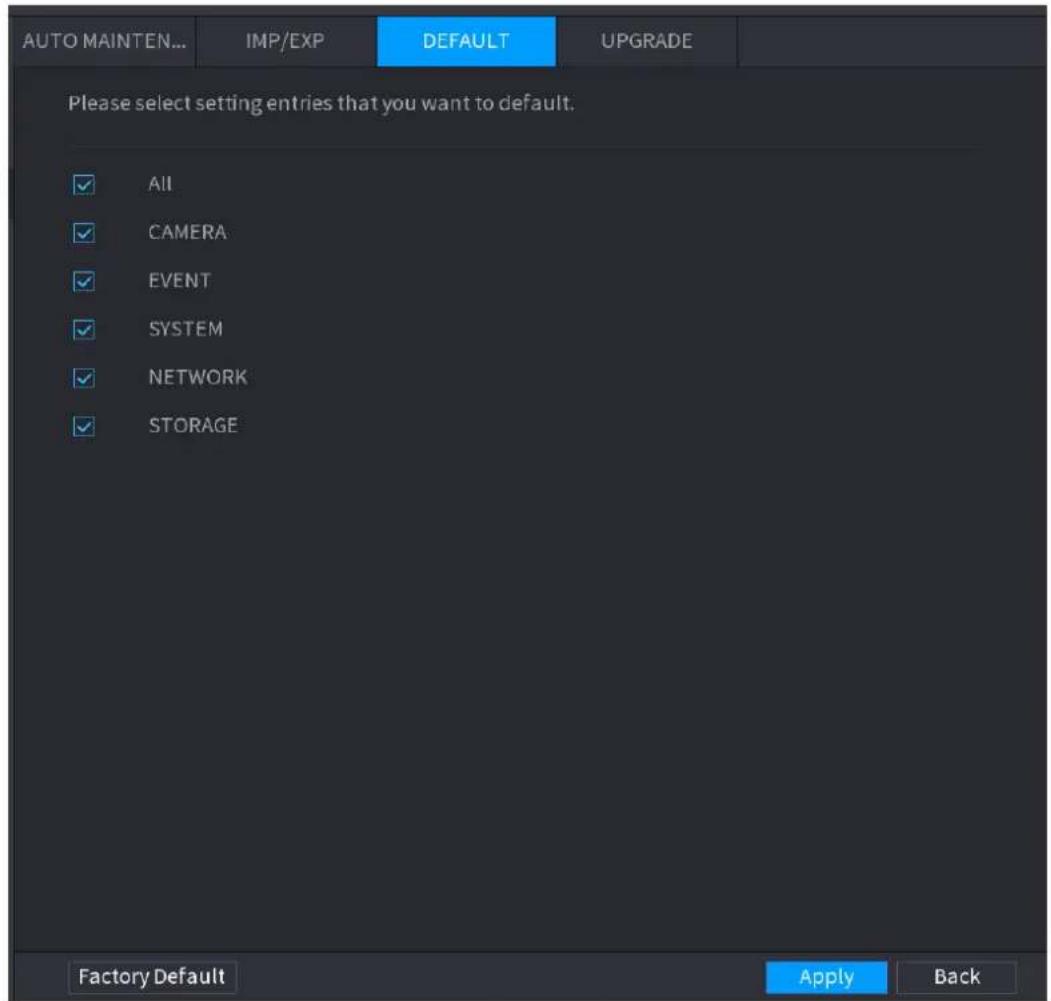
text_image
AUTO MAINTEN... IMP/EXP DEFAULT UPGRADE Please select setting entries that you want to default. ✓ All ✓ CAMERA ✓ EVENT ✓ SYSTEM ✓ NETWORK ✓ STORAGE Factory Default Apply BackStep 2 Restore the settings.
- Select the settings that you want to restore, and then click Apply. The system starts restoring the selected settings.
- Click Factory Default, and then click OK. The system starts restoring the whole settings.
4.10.4.4 System Update
4.10.4.4.1 Upgrading File
Step 1 Insert a USB storage device containing the upgrade files into the USB port of the Device.
Step 2 Select Main Menu > OPERATION > SYSTEM MAINTAIN > UPGRADE.
The UPGRADE interface is displayed. See Figure 4-198.
Figure 4-198
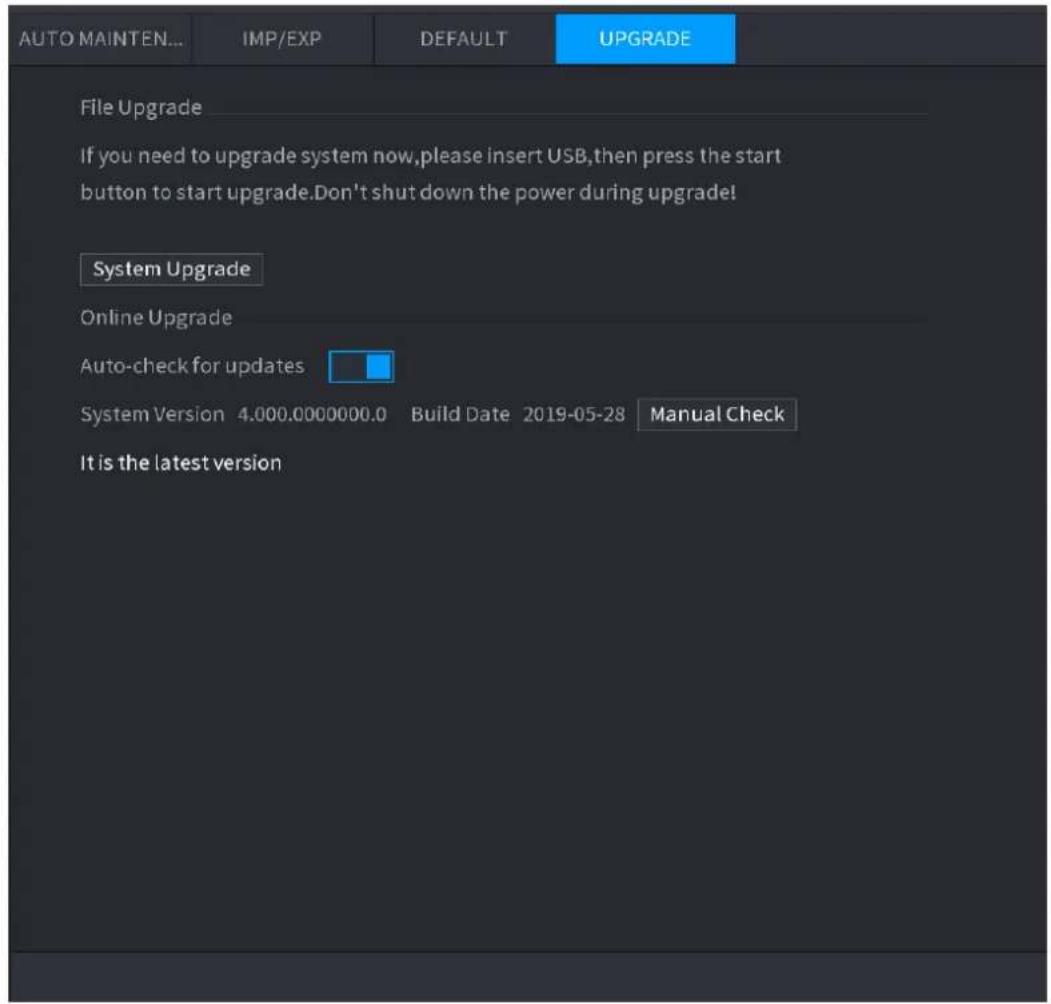
text_image
AUTO MAINTEN... IMP/EXP DEFAULT UPGRADE File Upgrade If you need to upgrade system now,please insert USB,then press the start button to start upgrade.Don't shut down the power during upgrade! System Upgrade Online Upgrade Auto-check for updates System Version 4.000.0000000.0 Build Date 2019-05-28 Manual Check It is the latest versionStep 3 Click System Upgrade.
The System Upgrade interface is displayed. See Figure 4-199.
Figure 4-199
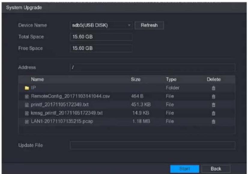
text_image
System Upgrade Device Name sdb5(USB DISK) Refresh Total Space 15.60 GB Free Space 15.60 GB Address // Name Size Type Delete IP Folder # RemoteConfig_20171103141044.csv 464 B File # printf_20171105172349.txt 451.3 KB File # kmsg_printf_20171105172349.txt 14.9 KB File # LAN1-20171107135215 pcap 1.18 MB File # Update File Start BackStep 4 Click the file that you want to upgrade.
The selected file is displayed in the Update File box.
Step 5 Click Start.
4.10.4.4.2 Online Upgrade
When the Device is connected to Internet, you can use online upgrade function to upgrade the system.
Before using this function, you need to check whether there is any new version by auto check or manual check.
● Auto check: The Device checks if there is any new version available at intervals.
- Manual check: Perform real-time check whether there is any new version available.

Ensure the correct power supply and network connection during upgrading; otherwise the upgrading might be failed.
Step 1 Select Main Menu >> OPERATION > SYSTEM MAINTAIN > UPGRADE.
The UPGRADE interface is displayed. See Figure 4-200.
Figure 4-200
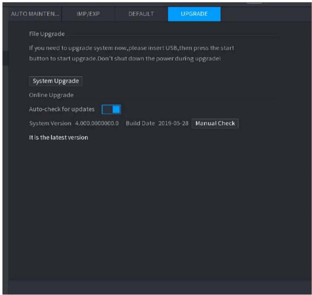
text_image
AUTO MAINTEN... IMP/EXP DEFAULT UPGRADE File Upgrade If you need to upgrade system now,please insert USB,then press the start button to start upgrade.Don't shut down the power during upgrade! System Upgrade Online Upgrade Auto-check for updates System Version 4.000.0000000.0 Build Date 2019-05-28 Manual Check It is the latest versionStep 2 Check whether there is any new version available.
- Auto-check for updates: Enable Auto-check for updates.
- Manual check: Click Manual Check.
The system starts checking the new versions. After checking is completed, the check result is displayed.
- If the "It is the latest version" text is displayed, you do not need to upgrade.
- If the text indicating there is a new version, go to the step 3.
Step 3 Click Upgrade now to update the system.
4.10.4.4.3 Uboot Upgrading

- Under the root directory in the USB storage device, there must be "u-boot.bin.img" file and "update.img" file saved, and the USB storage device must be in FAT32 format.
- Make sure the USB storage device is inserted; otherwise the upgrading cannot be performed.
When starting the Device, the system automatically check whether there is a USB storage device connected and if there is any upgrade file, and if yes and the check result of the upgrade file is correct, the system will upgrade automatically. The Uboot upgrade can avoid the situation that you have to upgrade through +TFTP when the Device is halted.
4.11 File Backup
You can back up the record file to the UBS device.
Step 1 Connect USB burner, USB device or portable HDD to the device.
Step 2 Select Main menu > BACKUP, the Backup interface is displayed. See Figure 4-201.
Figure 4-201
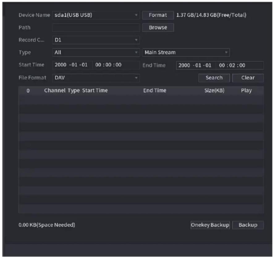
text_image
Device Name sda1(USB USB) Format 1.37 GB/14.83 GB(Free/Total) Path Browse Record C... D1 Type All Main Stream Start Time 2000 -01 -01 00 : 00 : 00 End Time 2000 -01 -01 00 : 02 : 00 File Format DAV Search Clear 0 Channel Type Start Time End Time Size(KB) Play 0.00 KB(Space Needed) Onekey Backup BackupStep 3 Select backup device and then set channel, file start time and end time.
Step 4 Click Search button, system begins search. All matched files are listed below. System automatically calculates the capacity needed and remained.
Step 5 System only backup files with a √ before channel name. You can use Fn or cancel button to delete √ after file serial number.
Step 6 Click backup button, you can backup selected files. There is a process bar for you reference.
Step 7 When the system completes backup, you can see a dialogue box prompting successful backup.
Step 8 Click Backup button, system begins burning. At the same time, the Backup button becomes Stop button. You can view the remaining time and process bar at the left bottom.

- During backup process, you can click ESC to exit current interface for other operation (For some series product only). The system will not terminate backup process. (This function is for some series products only.)
- System pops up corresponding dialogue box if there is no backup device, or no backup file, or error occurs during backup process.
- The file name format usually is: Channel number+Record type+Time. In the file name, the YDM format is Y+M+D+H+M+S. File extension name is .dav.
- Click Onekey Backup to back up all required files.
4.12 Network
You can set NVR network parameters so that the NVR can communicate with devices in the same LAN.
4.12.1 TCP/IP
Select Main Menu > NETWORK > TCP/IP, the TCP/IP interface is displayed. See Figure 4-202.
Figure 4-202
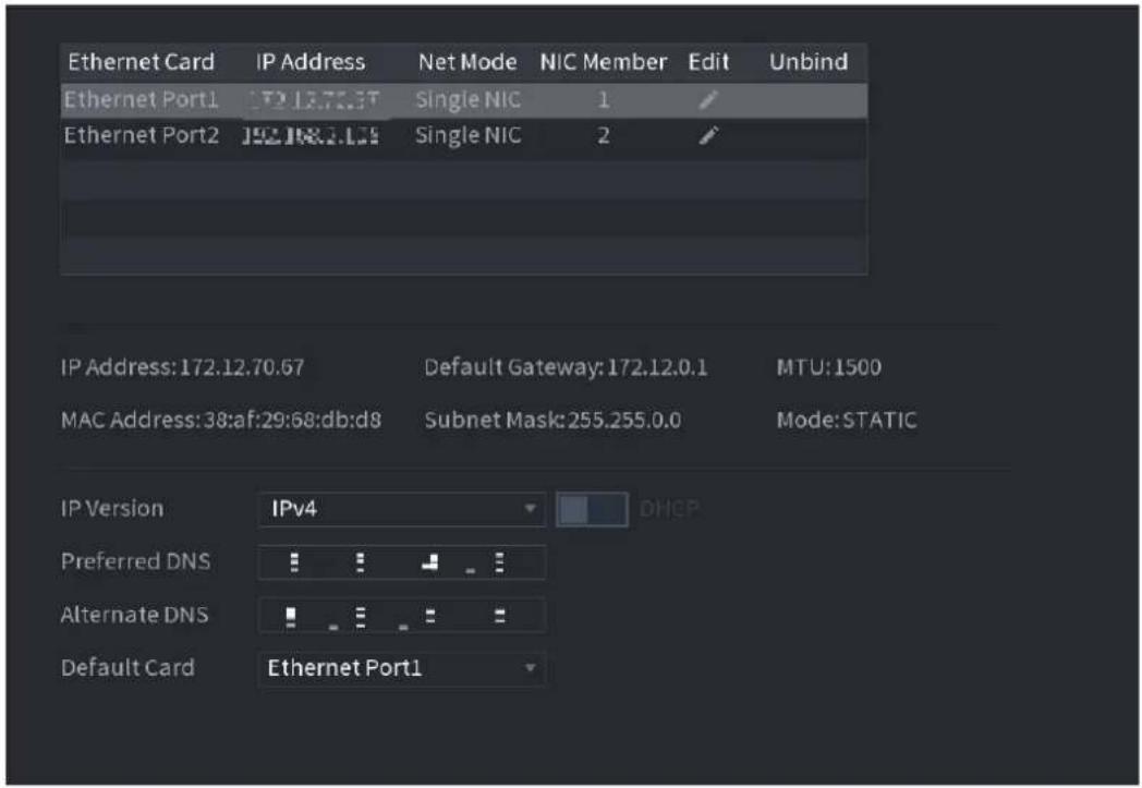
text_image
Ethernet Card IP Address Net Mode NIC Member Edit Unbind Ethernet Port1 172.13.70.3T Single NIC 1 Ethernet Port2 192.18.7.175 Single NIC 2 IP Address: 172.12.70.67 Default Gateway: 172.12.0.1 MTU: 1500 MAC Address: 38:af:29:68:db:d8 Subnet Mask: 255.255.0.0 Mode: STATIC IP Version IPv4 DHCP Preferred DNS Alternate DNS Default Card Ethernet Port1Table 4-53
| Parameter | Description |
| Net Mode | Multi-address: Two Ethernet ports work separately through either of which you can request the Device to provide the services such as HTTP and RTSP. You need to configure a default Ethernet port (usually the Ethernet port 1 by default) to request the services from the device end such as DHCP, Email and FTP. If one of the two Ethernet ports is disconnected as detected by networking testing, the system network status is regarded as offline.Fault Tolerance: Two Ethernet ports share one IP address.Normally only one Ethernet port is working and when this port fails, the other port will start working automatically to ensure the network connection.When testing the network status, the network is regarded as offline only when both of the two Ethernet ports are disconnected. The two Ethernet ports are used under the same LAN.Load Balance: Two network cards share one IP address and they are working at the same time to share the network load averagely. If one of them fails, the other can continue working normally.When testing the network status, the network is regarded as offline only when both of the two Ethernet ports are disconnected. The two Ethernet ports are used under the same LAN.The Device with single Ethernet port does not support this function. |
| Default Ethernet Port | In the Ethernet Card list, select an Ethernet port as a default port.This setting is available only when theMulti-addressis selected in the Net Mode list. |
| IP Version | In theIP Versionlist, you can selectIPv4orIPv6. Both versions are supported for access. |
| MAC Address | Displays the MAC address of the Device. |
| DHCP | Enable the DHCP function. The IP address, subnet mask and default gateway are not available for configuration once DHCP is enabled.If DHCP is effective, the obtained information will display in theIPAddressbox,Subnet Maskbox andDefault Gatewaybox. If not, all values show 0.0.0.0.If you want manually configure the IP information, disable the DHCP function first.If PPPoE connection is successful, the IP address, subnet mask, default gateway, and DHCP are not available for configuration. |
| IP Address | Enter the IP address and configure the corresponding subnet mask and default gateway. |
| Subnet Mask | |
| Default Gateway | IP address and default gateway must be in the same network segment. |
| DNS DHCP | Enable the DHCP function to get the DNS address from router. |
| Preferred DNS | In thePreferred DNSbox, enter the IP address of DNS. |
| Alternate DNS | In theAlternate DNSbox, enter the IP address of alternate DNS. |
| MTU | In theMTUbox, enter a value for network card. The value ranges from 1280 byte through 1500 byte. The default is 1500.The suggested MTU values are as below.1500: The biggest value of Ethernet information package. This value is typically selected if there is no PPPoE or VPN connection, and it is also the default value of some routers, network adapters and switches.1492: Optimized value for PPPoE.1468: Optimized value for DHCP.1450: Optimized value for VPN. |
| Test | Click Testto test if the entered IP address and gateway are interworking. |
4.12.2 Port
You can configure the maximum connection accessing the Device from Client such as WEB, Platform, and Mobile Phone and configure each port settings.
Step 1 Select Main Menu > NETWORK > PORT.
The PORT interface is displayed. See Figure 4-203.
Figure 4-203
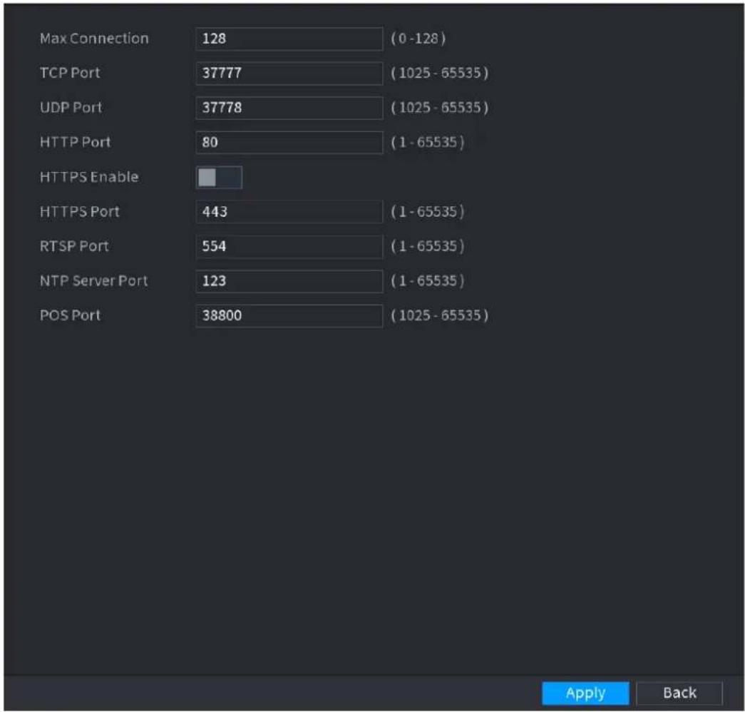
text_image
Max Connection 128 (0 -128) TCP Port 37777 (1025 - 65535) UDP Port 37778 (1025 - 65535) HTTP Port 80 (1 - 65535) HTTPS Enable HTTPS Port 443 (1 - 65535) RTSP Port 554 (1 - 65535) NTP Server Port 123 (1 - 65535) POS Port 38800 (1025 - 65535)Step 2 Configure the settings for the connection parameters. See Table 4-54.

The connection parameters except Max Connection cannot take effects until the Device has been restarted.
Table 4-54
| Parameter | Description |
| Max Connection | The allowable maximum clients accessing the Device at the same time, such as WEB, Platform, and Mobile Phone.Select a value between 1 and 128. The default value setting is 128. |
| TCP Port | The default value setting is 37777. You can enter the value according to your actual situation. |
| UDP Port | The default value setting is 37778. You can enter the value according to your actual situation. |
| HTTP Port | The default value setting is 80. You can enter the value according to your actual situation.If you enter other value, for example, 70, and then you should enter 70 after the IP address when logging in the Device by browser. |
| RTSP Port | The default value setting is 554. You can enter the value according to your actual situation. |
| POS Port | Data transmission. The value range is from 1 through 65535. The default value is 38800. |
| HTTPS Enable | Enable HTTPS. |
| HTTPS Port | HTTPS communication port. The default value setting is 443. You can enter the value according to your actual situation. |
Step 4 Click Apply to complete the settings.
4.12.3 PPPoE
PPPoE is another way for the Device to access the network. You can establish network connection by configuring PPPoE settings to give the Device a dynamic IP address in the WAN. To use this function, firstly you need to obtain the user name and password from the Internet Service Provider.
Step 1 Select Main Menu > NETWORK > PPPoE.
The PPPoE interface is displayed. See Figure 4-204.
Figure 4-204
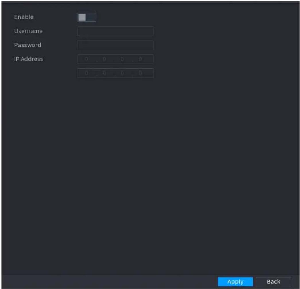
text_image
Enable Username Password IP Address 0 . 0 . 0 . 0 0 . 0 . 0 . 0 Apply BackStep 2 Enable the PPPoE function.
Step 3 In the User Name box and Password box, enter the user name and password accordingly provided by the Internet Service Provider.
Step 4 Click Apply to complete the settings.
The system pops up a message to indicate the successfully saved. The IP address appears on the PPPoE interface. You can use this IP address to access the Device.

When the PPPoE function is enabled, the IP address on the TCP/IP interface cannot be modified.
4.12.4 DDNS
When the IP address of the Device changes frequently, the DDNS function can dynamically refresh the correspondence between the domain on DNS and the IP address, ensuring you access the Device by using the domain.
Preparations
Ensure the Device supports the DDNS Type and log in the website provided by the DDNS service provider to register the information such as domain from PC located in the WAN.

After you have registered and logged in the DDNS website successfully, you can view the information of all the connected devices under this user name.
Step 1 Select Main Menu > NETWORK > DDNS.
The DDNS interface is displayed. See Figure 4-205.
Figure 4-205
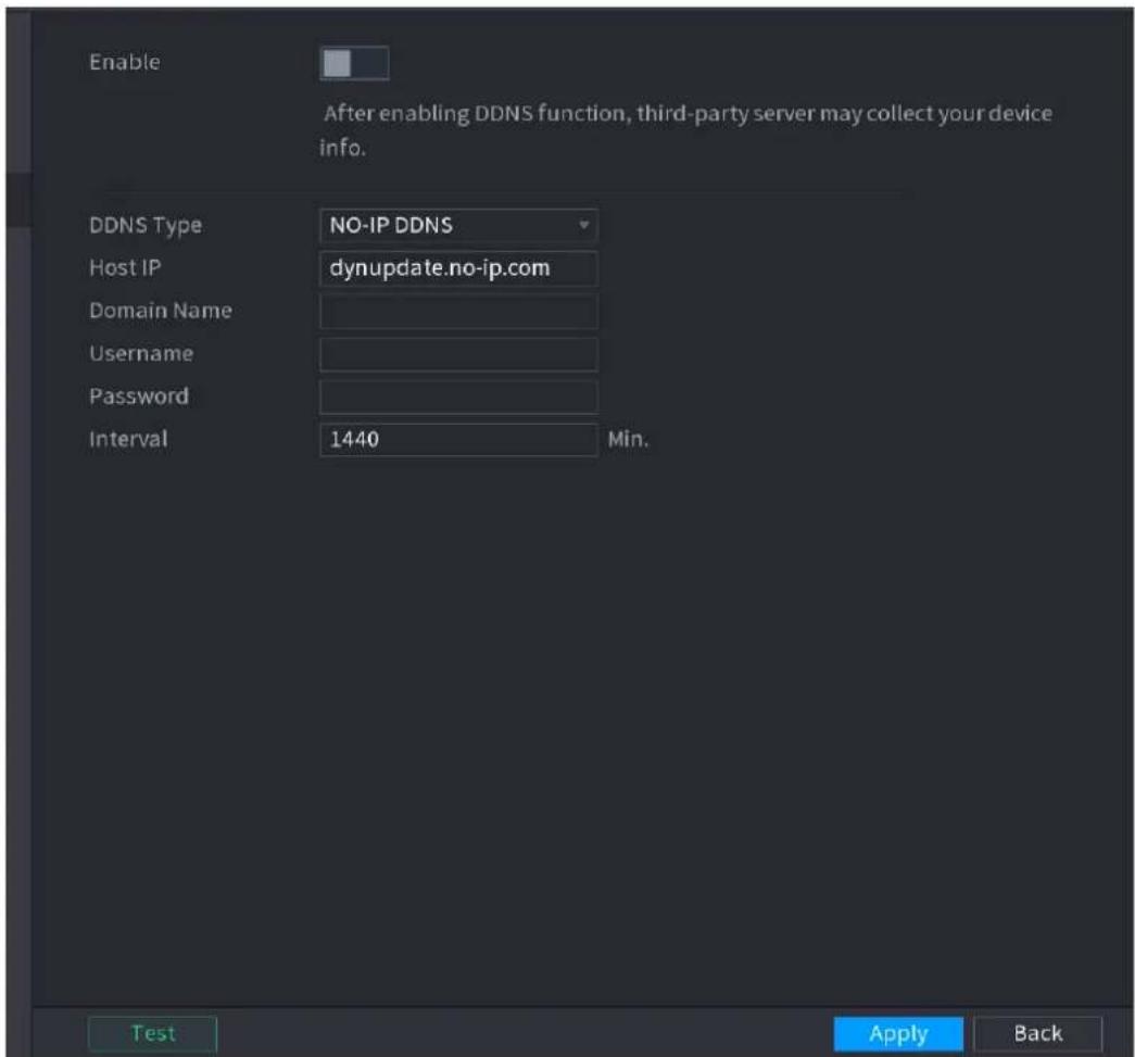
text_image
Enable After enabling DDNS function, third-party server may collect your device info. DDNS Type NO-IP DDNS Host IP dynupdate.no-ip.com Domain Name Username Password Interval 1440 Min. Test Apply BackStep 2 Configure the settings for the DDNS parameters. See Table 4-55.
Table 4-55
| Parameter | Description |
| Enable | Enable the DDNS function. |
| After enabling DDNS function, the third-party might collect you Device information. | |
| DDNS Type | Type and address of DDNS service provider. |
| Host IP | Type: Dyndns DDNS; address: members.dyndns.orgType: NO-IP DDNS; address: dynupdate.no-ip.comType: CN99 DDNS; address: members.3322.org |
| Domain Name | The domain name for registering on the website of DDNS service provider. |
| User Name | Enter the user name and password obtained from DDNS service provider. You need to register (including user name and password) on the website of DDNS service provider. |
| Password | |
| Interval | Enter the amount of time that you want to update the DDNS. |
Step 3 Click Apply to complete the settings.
Enter the domain name in the browser on your PC, and then press Enter.
If the web interface of the Device is displayed, the configuration is successful. If not, the configuration is failed.
4.12.5 UPnP
You can map the relationship between the LAN and the WAN to access the Device on the LAN through the IP address on the WAN.
Preparations
Login the router to set the WAN port to enable the IP address to connect into the WAN.
Enable the UPnP function at the router.
Connect the Device with the LAN port on the router to connect into the LAN.
Select Main Menu > NETWORK > TCP/IP, configure the IP address into the router IP address range, or enable the DHCP function to obtain an IP address automatically.
Configuration Steps
Step 1 Select Main Menu > NETWORK > UPnP.
The UPnP interface is displayed. See Figure 4-206.
Figure 4-206
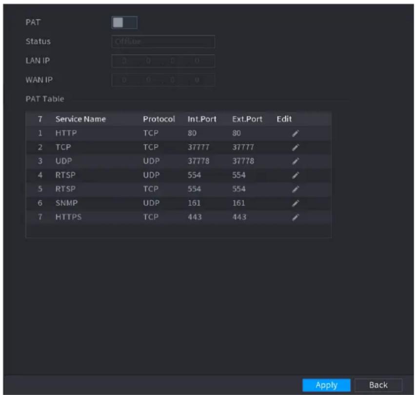
text_image
PAT Status Offline LAN IP 0 0 . 0 0 WAN IP 0 0 . 0 0 PAT Table 7 Service Name Protocol Int.Port Ext.Port Edit 1 HTTP TCP 80 80 ✓ 2 TCP TCP 37777 37777 ✓ 3 UDP UDP 37778 37778 ✓ 4 RTSP UDP 554 554 ✓ 5 RTSP TCP 554 554 ✓ 6 SNMP UDP 161 161 ✓ 7 HTTPS TCP 443 443 ✓ Apply BackFigure 4-207
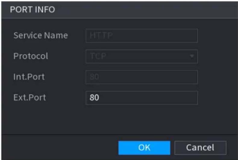
text_image
PORT INFO Service Name HTTP Protocol TCP Int.Port 80 Ext.Port 80 OK CancelStep 2 Configure the settings for the UPnP parameters. See Table 4-56.
Table 4-56
| Parameter | Description |
| PAT | Enable the UPnP function. |
| Status | Indicates the status of UPnP function.Offline: Failed.Online: Succeeded. |
| LAN IP | Enter IP address of router on the LAN.After mapping succeeded, the system obtains IP address automatically without performing any configurations. |
| WAN IP | Enter IP address of router on the WAN.After mapping succeeded, the system obtains IP address automatically without performing any configurations. |
| PAT Table | The settings in PAT table correspond to the UPnP PAT table on the router.Service Name: Name of network server.Protocol: Type of protocol.Int. Port: Internal port that is mapped on the Device.Ext. Port: External port that is mapped on the router.To avoid the conflict, when setting the external port, try to use the ports from 1024 through 5000 and avoid popular ports from 1 through 255 and system ports from 256 through 1023.When there are several devices in the LAN, properly arrange the ports mapping to avoid mapping to the same external port.When establishing a mapping relationship, ensure themapping ports are not occupied or limited.The internal and external ports of TCP and UDP must be the same and cannot be modified.Click t  dify the external port. dify the external port. |
Step 3 Click Apply to complete the settings.
In the browser, enter http://WAN IP: External IP port. You can visit the LAN Device.
4.12.6 Email
You can configure the email settings to enable the system to send the email as a notification when there is an alarm event occurs.
Step 1 Select Main Menu > NETWORK > EMAIL.
The EMAIL interface is displayed. See Figure 4-208.
Figure 4-208
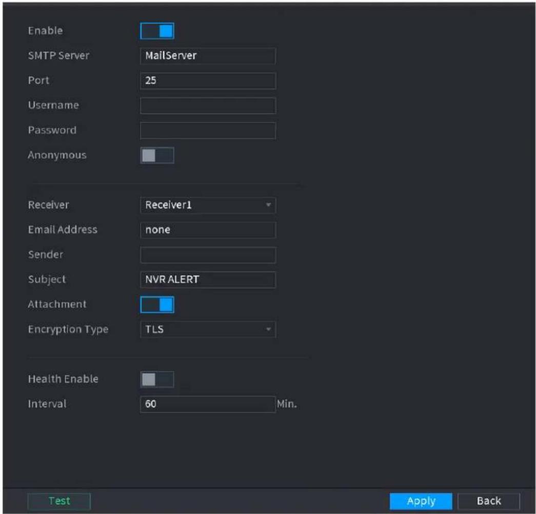
text_image
Enable SMTP Server MailServer Port 25 Username Password Anonymous Receiver Receiver1 Email Address none Sender Subject NVR ALERT Attachment Encryption Type TLS Health Enable Interval 60 Min. Test Apply BackStep 2 Configure the settings for the email parameters. See Table 4-57.
Table 4-57
| Parameter | Description |
| Enable | Enable the email function. |
| SMTP Server | Enter the address of SMTP server of sender's email account. |
| Port | Enter the port value of SMTP server. The default value setting is 25. You can enter the value according to your actual situation. |
| User Name | Enter the user name and password of sender's email account. |
| Password | |
| Anonymity | If enable the anonymity function, you can login as anonymity. |
| Mail Receiver | In the Mail Receiver list, select the number of receiver that you want to receive the notification. The Device supports up to three mail receivers. |
| Email Address | Enter the email address of mail receiver(s). |
| Sender | Enter the sender's email address. It supports maximum three senders separated by comma. |
| Title | Enter the email subject.Supports Chinese, English and Arabic numerals. It supports maximum 64 characters. |
| Attachment | Enable the attachment function. When there is an alarm event, the system can attach snapshots as an attachment to the email. |
| Authentication | Select the encryption type: NONE, SSL, or TLS.For SMTP server, the default encryption type is TLS. |
| Interval (Sec.) | This is the interval that the system sends an email for the same type of alarm event, which means, the system does not send an email upon any alarm event.This setting helps to avoid the large amount of emails caused by frequent alarm events.The value ranges from 0 to 3600. 0 means that there is no interval. |
| Health Enable | Enable the health test function. The system can send a test email to check the connection. |
| Interval (Min.) | This is the interval that the system sends a health test email.The value ranges from 30 to 1440. 0 means that there is no interval. |
| Test | Click Test to test the email sending function. If the configuration is correct, the receiver's email account will receive the email.Before testing, click Apply to save the settings. |
Step 3 Click Apply to complete the settings.
4.12.7 SNMP

This function is for some series only.
You can connect the Device with some software such as MIB Builder and MG-SOFT MIB
Browser to manage and control the Device from the software.
Preparations
- Install the software that can manage and control the SNMP, such as MIB Builder and MG-SOFT MIB Browser
- Obtain the MIB files that correspond to the current version from the technical support.
Configuration Steps
Step 1 Select Main Menu > NETWORK > SNMP.
The SNMP interface is displayed. See Figure 4-209.
Figure 4-209
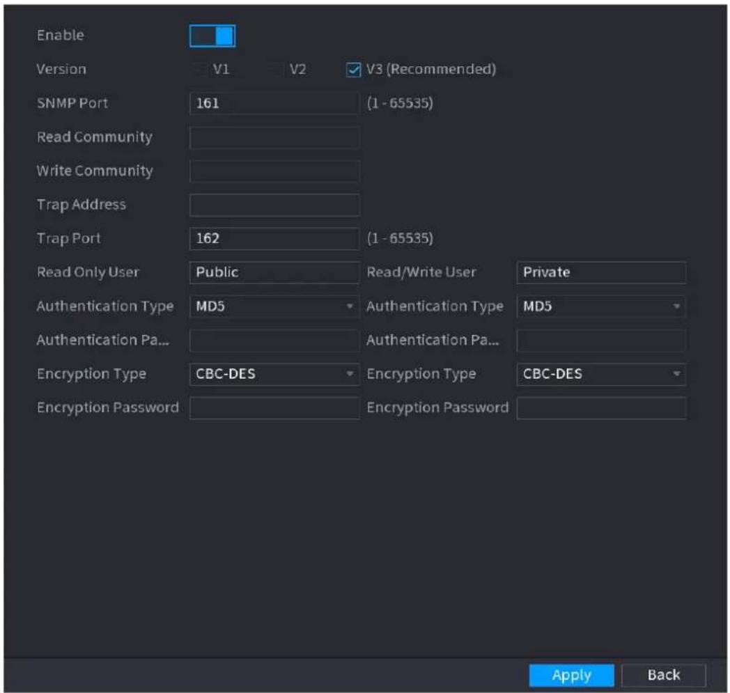
text_image
Enable Version V1 V2 V3 (Recommended) SNMP Port 161 (1 - 65535) Read Community Write Community Trap Address Trap Port 162 (1 - 65535) Read Only User Public Read/Write User Private Authentication Type MD5 Authentication Type MD5 Authentication Pa... Authentication Pa... Encryption Type CBC-DES Encryption Type CBC-DES Encryption Password Encryption Password Apply BackStep 2 Configure the settings for the SNMP parameters. See Table 4-58.
Step 3 Compile the two MIB files by MIB Builder.
Step 4 Run MG-SOFT MIB Browser to load in the module from compilation.
Step 5 On the MG-SOFT MIB Browser, enter the Device IP that you want to manage, and then select the version number to query.
Step 6 On the MG-SOFT MIB Browser, unfold the tree-structured directory to obtain the configurations of the Device, such as the channels quantity and software version.
Table 4-58
| Parameter | Description |
| Enable | Enable the SNMP function. |
| Version | Select the check box of SNMP version(s) that you are using. The default version is V3. There is a risk of select V1 or V2. |
| SNMP Port | Indicates the monitoring port on the agent program. |
| Read Community | Indicates the read/write strings supported by the agent program. |
| Write Community | |
| Trap Address | Indicates the destination address for the agent program to send the Trap information. |
| Trap Port | Indicates the destination port for the agent program to send the Trap information. |
| Read Only User | Enter the user name that is allowed to access the Device and has the "Read Only" permission. |
| Read/Write User | Enter the user name that is allowed to access the Device and has the "Read and Write" permission. |
| Authentication Type | Includes MD5 and SHA. The system recognizes automatically. |
| Authentication Password | Enter the password for authentication type and encryption type. The password should be no less than eight characters. |
| Encryption Password | |
| Encryption Type | In the Encryption Type list, select an encryption type. The default setting is CBC-DES. |
4.12.8 Multicast
When you access the Device from the network to view the video, if the access is exceeded, the video will not display. You can use the multicast function to group the IP to solve the problem.
Step 1 Select Main Menu > NETWORK > MULTICAST.
The MULTICAST interface is displayed. See Figure 4-210.
Figure 4-210
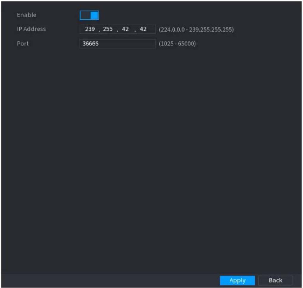
text_image
Enable IP Address 239 . 255 . 42 . 42 (224.0.0.0 - 239.255.255.255) Port 36666 (1025 - 65000) Apply BackStep 2 Configure the settings for the multicast parameters. See Table 4-59.
Table 4-59
| Parameter | Description |
| Enable | Enable the multicast function. |
| IP Address | Enter the IP address that you want to use as the multicast IP.The IP address ranges from 224.0.0.0 through 239.255.255.255. |
| Port | Enter the port for the multicast. The port ranges from 1025 through 65000. |
Step 3 Click Apply to complete the settings.
You can use the multicast IP address to login the web.
On the web login dialog box, in the Type list, select MULTICAST. The web will automatically obtain the multicast IP address and join. Then you can view the video through multicast function.
4.12.9 Alarm Centre
You can configure the alarm center server to receive the uploaded alarm information. To use this function, the Alarm Upload check box must be selected.
Step 1 Select Main Menu > NETWORK > ALARM CENTER.
The ALARM CENTER interface is displayed. See Figure 4-211.
Figure 4-211

text_image
Enable Protocol Type ALARM CENTER Host IP 10 . 1 . 0 . 2 Host IP 10 . 1 . 0 . 3 Port 1 Self-Report Time ALL 08:00 Apply BackStep 2 Configure the settings for the alarm center parameters. See Table 4-60.
Table 4-60
| Parameter | Description |
| Enable | Enable the alarm center function. |
| Protocol Type | In theProtocol Typelist, select protocol type. The default is ALARM CENTER. |
| Host IP | The IP address and communication port of the PC installed with alarm client. |
| Port | |
| Self-Report Time | In theSelf-Report Timelist, select time cycle and specific time for uploading alarm. |
Step 3 Click Apply to complete the settings.
4.12.10Register
You can register the Device into the specified proxy server which acts as the transit to make it easier for the client software to access the Device.
Step 1 Select Main Menu > NETWORK > REGISTER.
The REGISTER interface is displayed. See Figure 4-212.
Figure 4-212
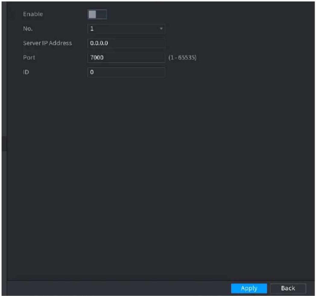
text_image
Enable No. 1 Server IP Address 0.0.0.0 Port 7000 (1 - 65535) ID 0 Apply BackStep 2 Configure the settings for the register parameters. See Table 4-61.
Table 4-61
| Function | Description |
| Enable | Enable the register function. |
| Server IP Address | Enter the server IP address or the server domain that you want to register to. |
| Port | Enter the port of the server. |
| Sub Service ID | This ID is allocated by the server and used for the Device. |
Step 3 Click Apply to complete the settings.
4.12.11P2P
P2P is a kind of convenient private network penetration technology. You do not need to apply for dynamic domain name, doing port mapping or deploying transit server. You can add NVR devices through the below way to achieve the purpose of managing multiple NVR devices at the same time.
- Scan the QR code, download mobile app, and then register an account. For details, see Mobile App Operation.
- Log in www.gotop2p.com, register an account, and then add device via the serial number.
For details, see Introduction of P2P Operations.

Connect the NVR device to the Internet, otherwise P2P can not run properly.
Step 1 Select Main Menu > NETWORK > P2P.
The P2P interface is displayed. See Figure 4-213.
Figure 4-213
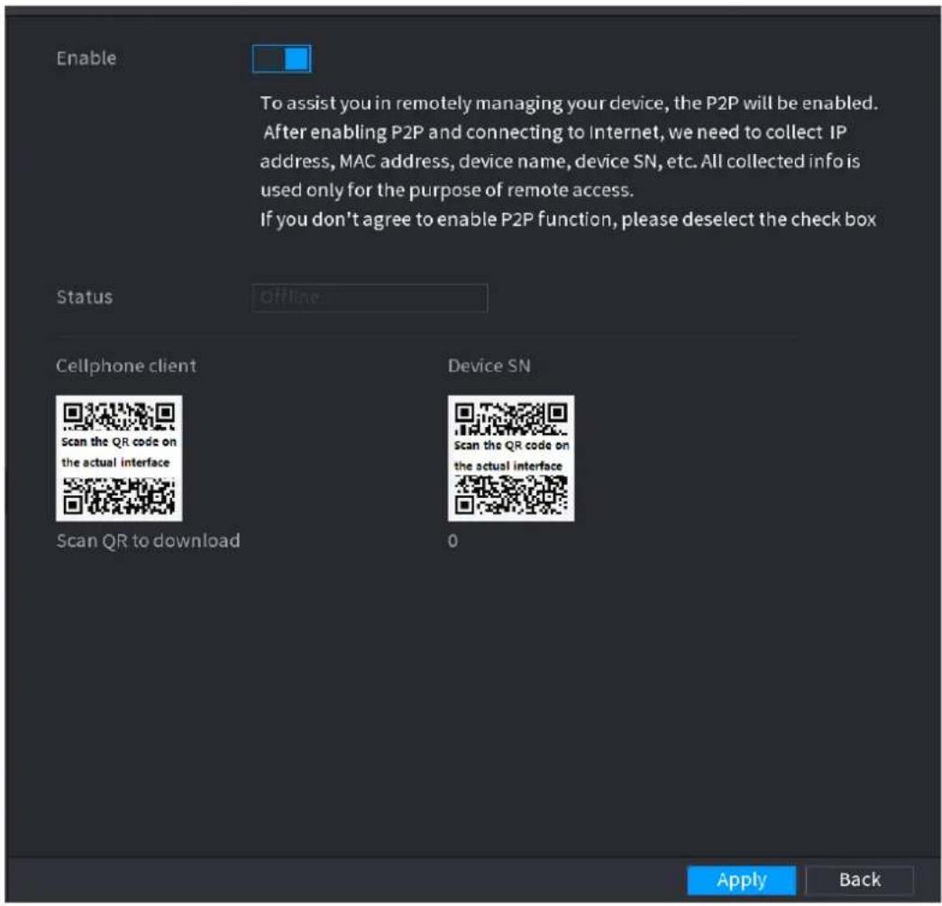
text_image
Enable To assist you in remotely managing your device, the P2P will be enabled. After enabling P2P and connecting to Internet, we need to collect IP address, MAC address, device name, device SN, etc. All collected info is used only for the purpose of remote access. If you don't agree to enable P2P function, please deselect the check box Status Offline Cellphone client Scan the QR code on the actual interface Scan QR to download Device SN Scan the QR code on the actual interface 0 Apply BackStep 2 Enable the P2P function.

After the P2P function is enabled and connected to the Internet, the system will collects your information for remote access, and the information includes but not limited to email address, MAC address, and device serial number.
You can start adding the device.
- Cell Phone Client: Use your mobile phone to scan the QR code to add the device into the Cell Phone Client, and then you can start accessing the Device.
- Platform: Obtain the Device SN by scanning the QR code. Go to the P2P management platform and add the Device SN into the platform. Then you can
access and manage the device in the WAN. For details, refer to the P2P operation manual.

You can also enter the QR code of Cell Phone Client and Device SN by clicking on the top right of the interfaces after you have entered the Main Menu.

To use this function, take adding device into Cell Phone Client as an example.
Mobile APP Operation
The following contents are introduced in the example of mobile App.
Step 1 Scan the QR code to download and install the mobile App.
Step 2 Select Camera and enter the main interface.
Step 3 Register device in the mobile App:
1) Click and select Device Manager. See Figure 4-214.
Figure 4-214
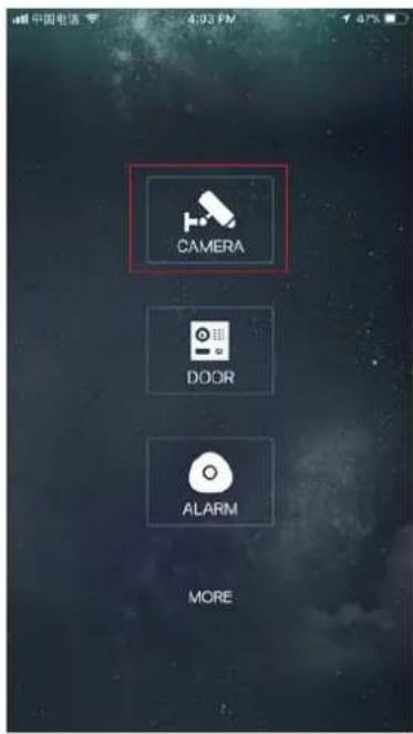
text_image
CAMERA DOOR ALARM MORE
text_image
Live Preview OKs OKs OKs OKs OKs OKs OKs OKs OKs OKs OKs OKs OKs OKs OKs OKs OKs OKs OKs OKs OKs OKs OKs OKs OKs OKs OKs OKs OKs OKs OKs OKs OKs OKs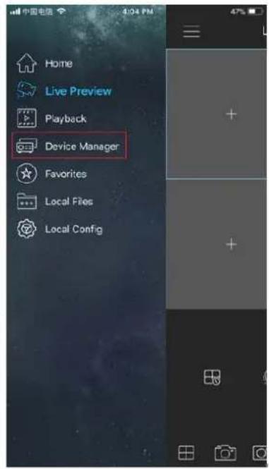
text_image
Home Live Preview Playback Device Manager Favorites Local Files Local Config2) Click and enter the Add Device interface.
2.
- Mobile App supports device initialization.
3) Select Wired Device > P2P to enter the P2P interface.
4) Click the QR code icon behind the SN to enter the QR code scan interface.
5) Scan the device label or scan the SN QR code got by selecting Main Menu > Network > P2P. When the scan is successful, the device SN will be displayed in the SN item.
6) Enter name and password.
Step 4 After device registration on mobile App, click Start Preview and you can see the monitor screen.
4.12.12802.1X
Device needs to pass 802.1x certification to enter the LAN.
Step 1 Select Main Menu > NETWORK > 802.1x.
The 802.1x interface is displayed. See Figure 4-215 or Figure 4-216.
Figure 4-215
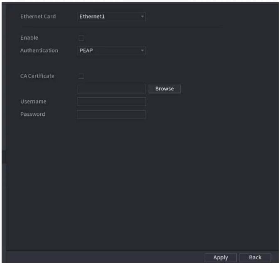
text_image
Ethernet Card Ethernet1 Enable Authentication PEAP CA Certificate Browse Username Password Apply BackFigure 4-216
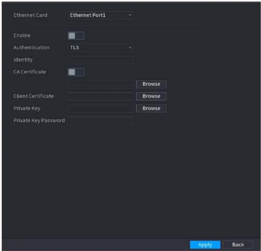
text_image
Ethernet Card Ethernet Port1 Enable Authentication TLS Identity CA Certificate Browse Client Certificate Browse Private Key Browse Private Key Password Apply BackStep 2 Select the Ethernet card you want to certify.
Step 3 Select Enable and configure parameters. See Table 4-62.
Table 4-62
| Parameter | Description |
| Authentication | PEAP: protected EAP protocol.TLS: Transport Layer Security. Provide privacy and data integrity between two communications application programs. |
| Identity | It can be configured when Authentication is TLS. |
| CA Certificate | Enable it and click Browse to import CA certificate from flash drive. |
| Username | The username shall be authorized at server. |
| Password | Password of the corresponding username. |
| Client Certificate | When Authentication is TLS, click Browse to import from flash drive. |
| Private Key | |
| Private Key Password | It can be configured when Authentication is TLS. |
Step 4 Click Apply to complete the settings.
4.13 Storage
You can manage the storage resources (such as record file) and storage space. So that it is easy for you to use and enhance storage space usage.
4.13.1 Basic
You can set basic storage parameters.
Step 1 Select Main Menu > STORAGE > BASIC.
The Basic interface is displayed. See Figure 4-217.
Figure 4-217
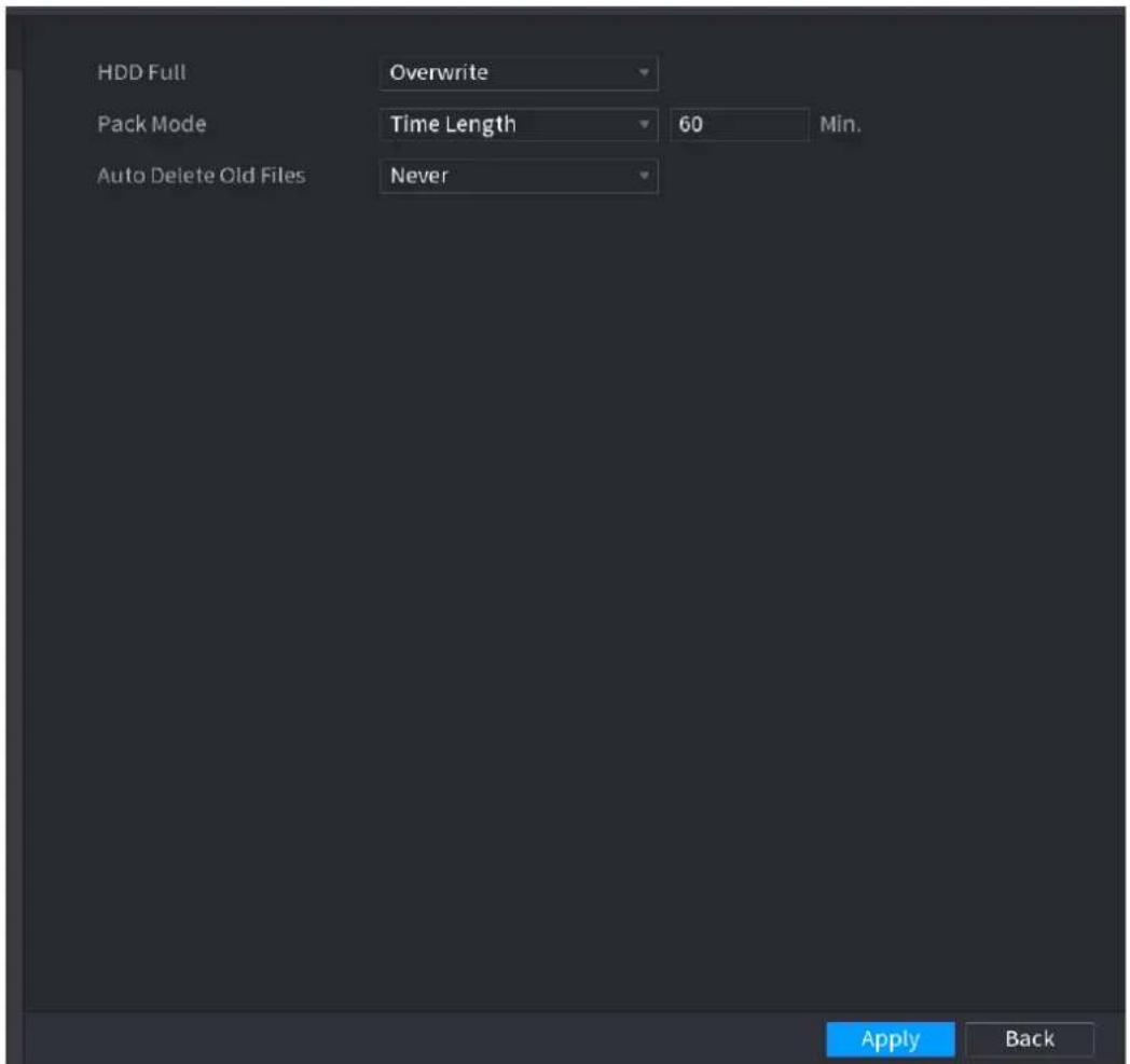
text_image
HDD Full Overwrite Pack Mode Time Length 60 Min. Auto Delete Old Files Never Apply BackStep 2 Set parameters. See Table 4-63.
Table 4-63
| Parameter | Description |
| HDD Full | Configure the settings for the situation all the read/write discs are full, and there is no more free disc.SelectStop Recordto stop recordingSelectOverwriteto overwrite the recorded video files always from the earliest time. |
| Pack Mode | Configure the time length and file length for each recorded video. |
| Auto-Delete Old Files | Configure whether to delete the old files and if yes, configure the days.The auto delete file cannot be recovered! |
Step 3 Click Apply or Save to complete setup.
4.13.2 Schedule
You can set schedule record and schedule snapshot. NVR can record or snapshot as you specified. For detailed information, refer to "4.1.4.6.1 Schedule Record" and "4.1.4.6.2 Schedule Snapshot".
4.13.3 HDD
You can view and sett HDD properties and format HDD.
You can view current HDD type, status, capacity and etc. The operation includes format HDD, and change HDD property (read and write/read-only/redundancy).
● To prevent files be overwritten in the future, you can set HDD as read-only.
● To backup recorded video file, you can set HDD as redundant HDD.
Step 1 Select Main Menu > Storage > HDD MANAGER, The HDD MANAGER interface is displayed. See Figure 4-218.
Figure 4-218
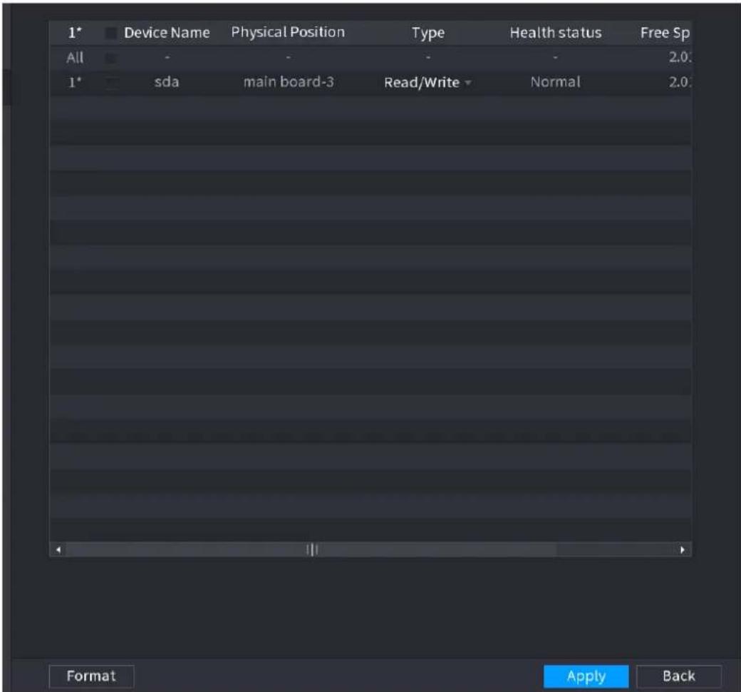
text_image
1* Device Name Physical Position Type Health status Free Sp All - - - 2.0 1* sda main board-3 Read/Write Normal 2.0 Format Apply BackStep 2 Select a HDD and then select a time from the dropdown list.
Step 3 Click Apply button to complete the setup. System needs to restart to activate current setup if you want to format the HDD.
4.13.4 Record Control
After you set schedule record or schedule snapshot function, set auto record/snapshot function so that the NVR can automatically record or snapshot. For detailed information, refer to "4.1.4.6.3 Record Control".
4.13.5 Advance (HDD Group)
You can set HDD group, and HDD group setup for main stream, sub stream and snapshot operation.

When you are setting HDD group, set a HDD for each channel, otherwise NVR cannot save current setup.
Step 1 Select Main Menu > STORAGE > ADVANCED.
The ADVANCED interface is displayed. See Figure 4-219.
Figure 4-219

text_image
HDD Main Stream Sub Stream Snapshot Device Name Group Apply BackStep 2 Select the group for each HDD group, and then click Save to save the settings.
After configuring HDD group, under the Main Stream tab, Sub Stream tab and Snapshot tab, configure settings to save the main stream, sub stream and snapshot to different HDD group as selected by you.
4.13.6 HDD Detect

This function is for some series product only.
The HDD detect function is to detect HDD current status so that you can clearly understand the HDD performance and replace the malfunction HDD.
There are two detect types:
- Quick detect is to detect via the universal system files. System can quickly complete the HDD scan. If you want to use this function, make sure the HDD is in use now. If the HDD is removed from other device, make sure the HDD once storage the record files when installed on current device.
- Global detect adopts Windows mode to scan. It may take a long time and may affect the HDD that is recording.
4.13.6.1 Manual Detect
Step 1 Select Main Menu > STORAGE > HDD DETECT > Manual Detect.
The Manual Detect interface is displayed. See Figure 4-220.
Figure 4-220
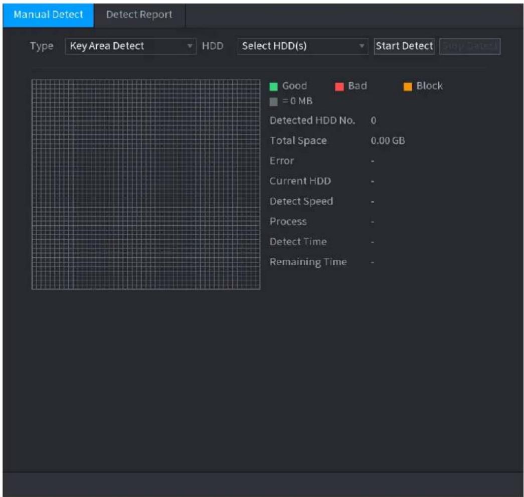
text_image
Manual Detect Detect Report Type Key Area Detect HDD Select HDD(s) Start Detect Stop Status Good Bad Block = 0 MB Detected HDD No. 0 Total Space 0.00 GB Error - Current HDD - Detect Speed - Process - Detect Time - Remaining Time -Step 2 In the Type list, select Key Area Detect or Global Detect; and in the HDD list, select the HDD that you want to detect.
Step 3 Click Start Detect.
The system starts detecting the HDD and displays the detection information.

When system is detecting HDD, click Stop Detect to stop current detection. Click Start Detect to detect again.
4.13.6.2 Detect Report
After the detect operation, you can go to the detect report to view corresponding information. Replace the malfunction HDD in case there is data loss.
Step 1 Select Main Menu > STORAGE > HDD DETECT > Detect Report.
The Detect Report interface is displayed. See Figure 4-221.
Figure 4-221
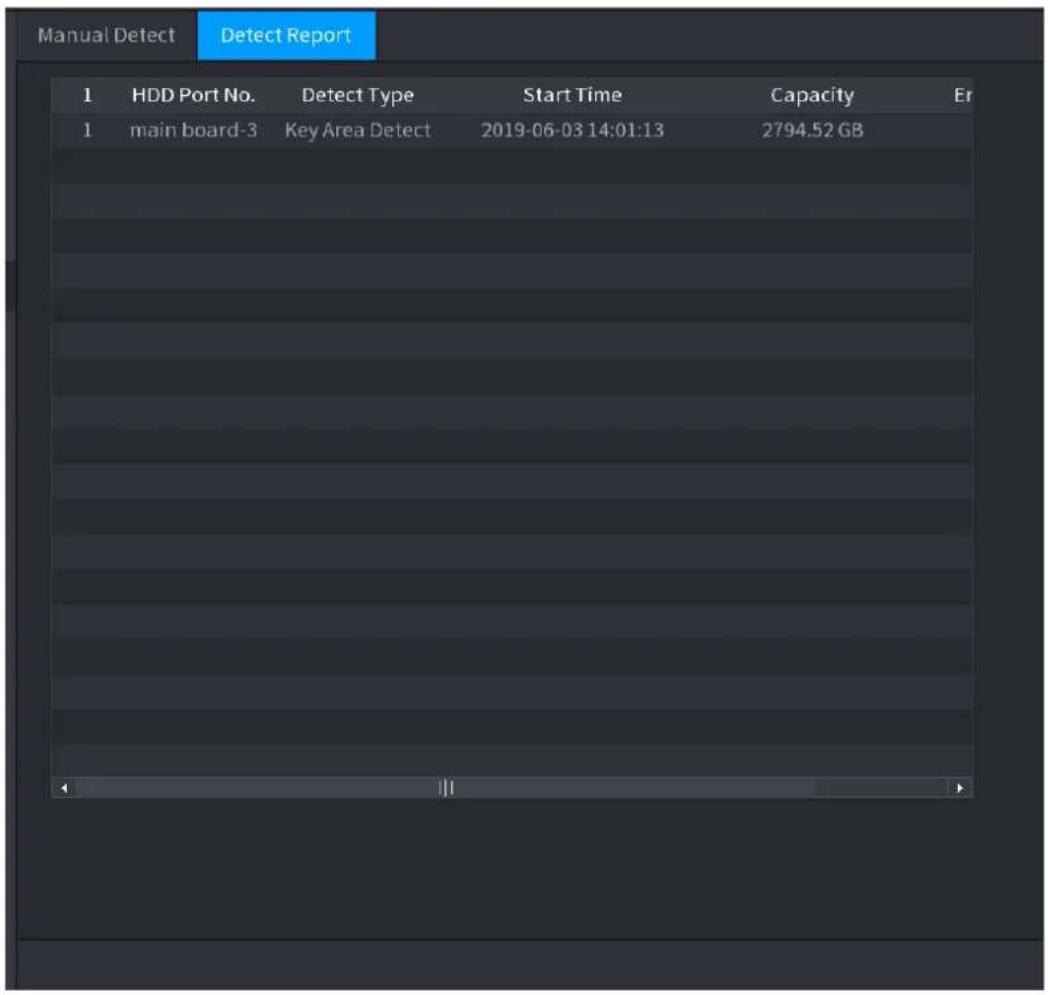
text_image
Manual Detect Detect Report 1 HDD Port No. Detect Type Start Time Capacity Er 1 main board-3 Key Area Detect 2019-06-03 14:01:13 2794.52 GBStep 2 Click

The Details interface is displayed. You can view detecting results and S.M.A.R.T reports. See Figure 4-222 and Figure 4-223.
Figure 4-222
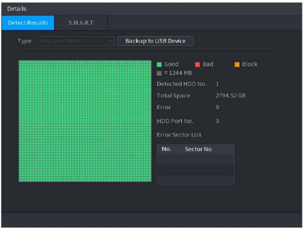
text_image
Details Detect Results S.M.A.R.T Type Key Area Detect Backup to USB Device Good Bad Block = 1244 MB Detected HDD No. 1 Total Space 2794.52 GB Error 0 HDD Port No. 3 Error Sector List No. Sector NoFigure 4-223

text_image
Details Detect Results S.M.A.R.T Port main board-3 Module No. 213975 Status HDD state is good Describe: Smart ID Attribute Threshold Value Worst Value Current Value 1 Read Error Rate 6 118 99 190702592 3 Spin Up Time 0 96 93 0 4 Start/Stop Count 20 69 69 32115 5 Reallocated Sector Count 10 100 100 0 7 Seek Error Rate 30 57 53 9836840581574.13.7 RAID
RAID (redundant array of independent disks) is a data storage virtualization technology that
combines multiple physical HDD components into a single logical unit for the purposes of data redundancy, performance improvement, or both.

- RAID function is for some series products only. Slight difference may be found on the user interface.
- The NVR supports RAID0, RAID1, RAID5, RAID6, and RAID 10. Local hot spare supports RAID1, RAID5, RAID6, and RAID10.
For the disk quantity required for each RAID type. See Table 4-64.
Table 4-64
| RAID type | Required disk quantity |
| RAID0 | At least 2. |
| RAID1 | Only 2. |
| RAID5 | At least 3, and using 4 disks to 6 disks is recommended. |
| RAID6 | At least 4. |
| RAID10 | At least 4. |
4.13.7.1 Creating Manager
RAID has different levels (such as RAID5, RAID6). Each level has different data protection, data availability, and performance grade.
You can manually create RAID or just one click one button to create RAID. For create RAID function, you can select the physical HDD that does not include in the RAID group or the created disk array to create a RAID5. You can refer to the following situations:
- There is no RAID, no hotspare disk: System directly creates the RAID5 and creates one hotspare disk at the same time.
- There is no RAID, but there is a hotspare disk: System creates the RAID5 only. It uses previous hotspare disk.
- There is RAID: System cancel the previous RAID setup and then create the new RAID5. System creates the hotspare disk if there is no one. System uses previous hotspare disk if there is hotspare disk available.
- The background will format the virtual disk.
You can create different types of RAID as needed.
Step 1 Select Main Menu > STORAGE > RAID > RAID.
The RAID interface is displayed. See Figure 4-224.
Figure 4-224
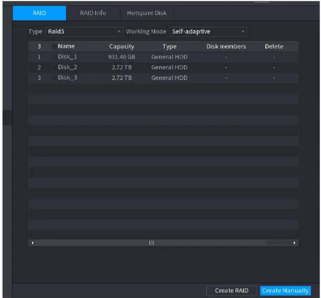
text_image
RAID RAID Info Hotspare Disk Type Raid5 Working Mode Self-adaptive 3 Name Capacity Type Disk members Delete 1 Disk_1 931.46 GB General HDD - 2 Disk_2 2.72 TB General HDD - 3 Disk_3 2.72 TB General HDD - Create RAID Create ManuallyStep 2 You can click Create RAID or Create Manually, and all the disks involved will be formatted.
- Click Create RAID, the system will create RAID automatically.
If there is no existing RAID and no hot spare disk, the system will create RAID5 and a hot spare disk automatically.
If there is no existing RAID, but existing hot spare disk, the system will only create RAID5 and use the existing hot spare disk automatically.
If there is existing RAID and existing hot spare disk, the system will delete the original RAID and create RAID5 with all the disks and use the existing hot spare disk automatically.
- Click Create Manually.
1) Select RAID type and disks as system instructed.
2) Click Create Manually, and then the format disk notice is displayed.
3) Click OK.
Step 3 After creating RAID, the disks need to sync with each other to finish the process. For RAID5 and RAID6, you can select different working mode.
- Self-Adaptive: Automatically adjust the RAID sync speed according to the business status.
When there is no business running, sync is performed at a high speed.
When there is business running, sync is performed at a low speed.
- Sync First: Resource priority is assigned to RAID sync.
• Business First: Resource priority is assigned to business operations.
• Balance: Resource is evenly distributed to RAID sync and business operations.
4.13.7.2 Raid Info
You can view the existing RAID information, including type, disk space, hot spare, and status.
Select Main Menu > STORAGE > RAID > RAID Info.
The RAID Info interface is displayed. See Figure 4-225.
Figure 4-225
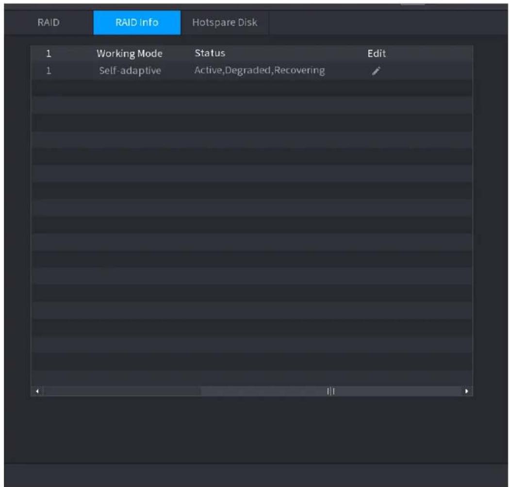
text_image
RAID RAID Info Hotspare Disk 1 Working Mode Status Edit 1 Self-adaptive Active,Degraded,Recovering4.13.7.3 Hot Spare Disk
You can add a hot spare disk to a specific disk in the RAID or to the entire RAID, and the hot spare disk is switched into operation if any disk fails.
Step 1 Select Main Menu > STORAGE > RAID > Hotspare Disk.
The Hotspare Disk interface is displayed. See Figure 4-226.
Figure 4-226
| RAID | RAID Info | Hotspare Disk | ||||
| 3 | Name | Capacity | Type | RAID Name | Edit | Delete |
| 1 | Disk_1 | 931.46 GB | General HDD | - | / | - |
| 2 | Disk_2 | 2.72 TB | General HDD | - | / | - |
| 3 | Disk_3 | 2.72 TB | General HDD | - | / | - |
Step 2 Click the icon behind a disk.
Step 3 The New Hotspare interface is displayed. See Figure 4-227 (New hot spare (local) or Figure 4-228 (New hot spare (global).
Figure 4-227
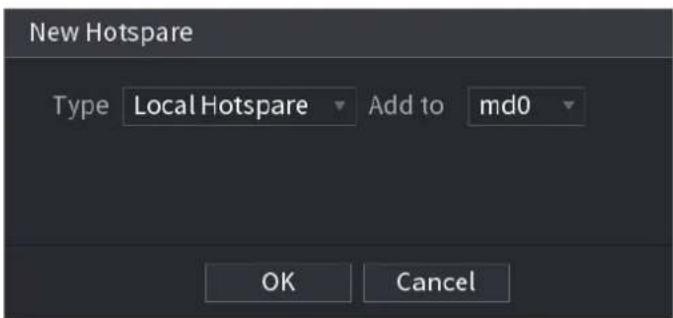
text_image
New Hotspare Type Local Hotspare Add to md0 OK CancelFigure 4-228
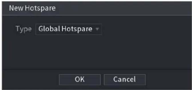
text_image
New Hotspare Type Global Hotspare OK CancelStep 4 You can select Local Hotspare or Global Hotspare.
- Local Hotspare: Select the target disk, and the new disk will serve as the hot spare disk of the selected disk.
- Global Hotspare: the new disk will serve as the hot spare disk of the entire RAID.
Step 5 Click OK.

Click behind a hot spare disk to delete it.
4.13.8 Record Estimate
Record estimate function can calculate how long you can record video according to the HDD capacity, and calculate the required HDD capacity according to the record period.
Step 1 Select Main Menu > STORAGE > REC ESTIMATE.
The REC ESTIMATE interface is displayed. See Figure 4-229.
Figure 4-229
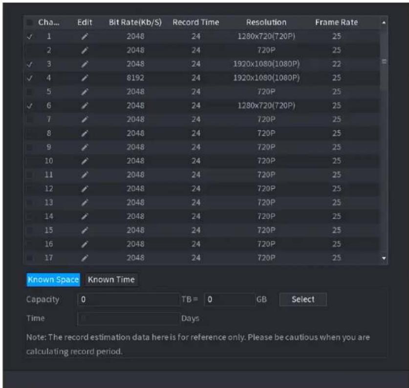
text_image
Cha... Edit Bit Rate(Kb/S) Record Time Resolution Frame Rate ✓ 1 ✓ 2048 24 1280x720(720P) 2 2 2048 24 720P ✓ 3 ✓ 2048 24 1920x1080(1080P) ✓ 4 ✓ 8192 24 1920x1080(1080P) 5 ✓ 2048 24 720P ✓ 6 ✓ 2048 24 1280x720(720P) 7 ✓ 2048 24 720P 8 ✓ 2048 24 720P 9 ✓ 2048 24 720P 10 ✓ 2048 24 720P 11 ✓ 2048 24 720P 12 ✓ 2048 24 720P 13 ✓ 2048 24 720P 14 ✓ 2048 24 720P 15 ✓ 2048 24 720P 16 ✓ 2048 24 720P 17 ✓ 2048 24 720P Known Space Known Time Capacity TB = 0 GB Select Time Days Note: The record estimation data here is for reference only. Please be cautious when you are calculating record period.Step 2 Click

The Edit dialogue box is displayed. See Figure 4-230.
You can configure the Resolution, Frame Rate, Bit Rate and Record Time for the selected channel.
Figure 4-230
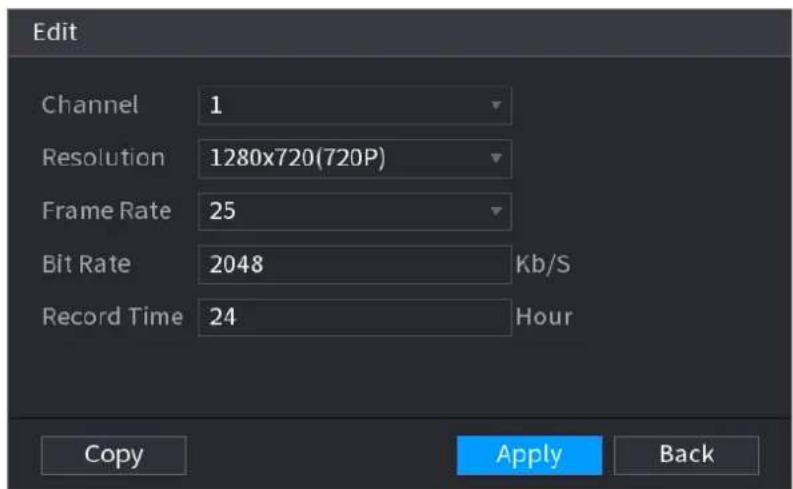
text_image
Edit Channel 1 Resolution 1280x720(720P) Frame Rate 25 Bit Rate 2048 Kb/S Record Time 24 Hour Copy Apply BackStep 3 Click Apply to save the settings.
Then the system will calculate the time period that can be used for storage according to the channels settings and HDD capacity.

Click Copy to copy the settings to other channels.
Calculating Recording Time
Step 1 On the REC ESTIMATE interface, click the Known Space tab.
The Known Space interface is displayed. See Figure 4-231.
Figure 4-231
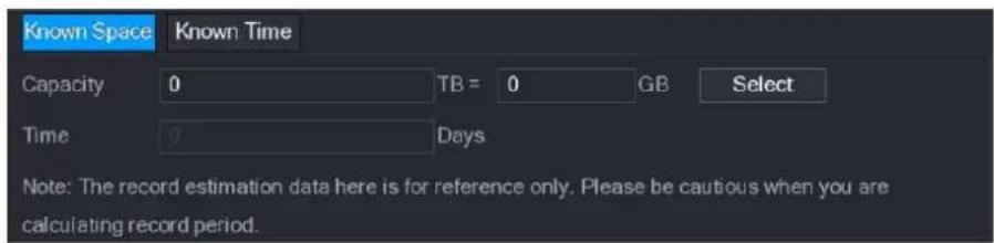
text_image
Known Space Known Time Capacity 0 TB = 0 GB Select Time 0 Days Note: The record estimation data here is for reference only. Please be cautious when you are calculating record period.Step 2 Click Select.
The Select HDD(s) interface is displayed.
Step 3 Select the check box of the HDD that you want to calculate.
In the Known Space tab, in the Time box, the recording time is displayed. See Figure 4-232.
Figure 4-232
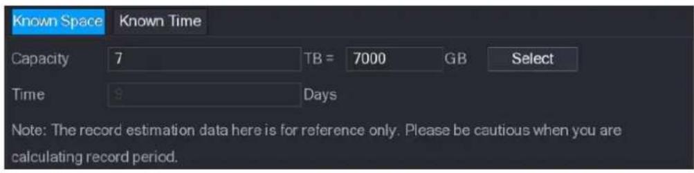
text_image
Known Space Known Time Capacity 7 TB = 7000 GB Select Time $ Days Note: The record estimation data here is for reference only. Please be cautious when you are calculating record period.Calculating HDD Capacity for Storage
Step 1 On the REC ESTIMATE interface, click the Known Time tab. The Known Time interface is displayed. See Figure 4-233.
Figure 4-233

text_image
Known Space Known Time Time 0 Days Capacity 0 TB = 0 GB Note: The record estimation data here is for reference only. Please be cautious when you are calculating record period.Step 2 In the Time box, enter the time period that you want to record. In the Capacity box, the required HDD capacity is displayed.
4.13.9 FTP
You can store and view the recorded videos and snapshots on the FTP server.
Preparations
Purchase or download a FTP (File Transfer Protocol) server and install it on your PC.

For the created FTP user, you need to set the write permission; otherwise the upload of recorded videos and snapshots will be failed.
Step 1 Select Main Menu > STORAGE > FTP.
The FTP interface is displayed. See Figure 4-234.
Figure 4-234
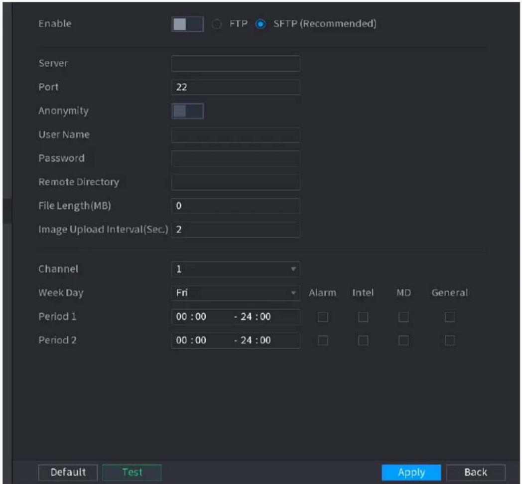
text_image
Enable FTP SFTP (Recommended) Server Port 22 Anonymity User Name Password Remote Directory File Length(MB) 0 Image Upload Interval(Sec.) 2 Channel 1 Week Day Fri Alarm Intel MD General Period 1 00:00 - 24:00 Period 2 00:00 - 24:00 Default Test Apply BackStep 2 Configure the settings for the FTP settings parameters. See Table 4-65.
Step 3 Click Test.
The system pops up a message to indicate success or failure. If failed, check the network connection or configurations.
Table 4-65
Step 4 Click Apply to complete the settings.
| Parameter | Description |
| Enable | ● Enable the FTP upload function. |
| FTP type | ● Select FTP type.● FTP: Plaintext transmission.● SFTP: Encrypted transmission (recommended) |
| Server | IP address of FTP server. |
| Port | ● FTP: The default is 21.● SFTP: The default is 22. |
| Anonymity | Enter the user name and password to login the FTP server. |
| User Name | Enable the anonymity function, and then you can login anonymously without entering the user name and password. |
| Password | |
| Remote Directory | Create folder on FTP server.If you do not enter the name of remote directory, system automatically creates the folders according to the IP and time.If you enter the name of remote directory, the system creates the folder with the entered name under the FTP root directory first, and then automatically creates the folders according to the IP and time. |
| File Length(M) | Enter the length of the uploaded recorded video.If the entered length is less than the recorded video length, only a section of the recorded video can be uploaded.If the entered length is more than the recorded video length, the whole recorded video can be uploaded.If the entered length is 0, the whole recorded video will be uploaded. |
| Image Upload Interval (Sec.) | If this interval is longer than snapshot interval, the system takes the recent snapshot to upload. For example, the interval is 5 seconds, and snapshot interval is 2 seconds per snapshot, the system uploads the recent snapshot every 5 seconds.If this interval is shorter than snapshot interval, the system uploads the snapshot per the snapshot interval. For example, the interval is 5 seconds, and snapshot interval is 10 seconds per snapshot, the system uploads the snapshot every 10 seconds.To configure the snapshot interval, selectMain Menu > CAMERA > ENCODE > Snapshot. |
| Channel | Select the channel that you want to apply the FTP settings. |
| Week Day | Select the week day and set the time period that you want to upload the recorded files. You can set two periods for each week day. |
| Period 1, Period 2 | |
| Record type | Select the record type (Alarm, Intel, MD, and General) that you want to upload. The selected record type will be uploaded during the configured time period. |
4.14 System
4.14.1 General
You can set device general information. It includes device information, system date. Refer to "4.1.4.1 General" for detailed information.
4.14.2 RS232
After setting RS-232 parameters, the NVR can use the COM port to connect to other device to debug and operate.
Step 1 Select MAIN MENU > SYSTEM >RS232.
The RS232 interface is displayed. See Figure 4-235.
Figure 4-235
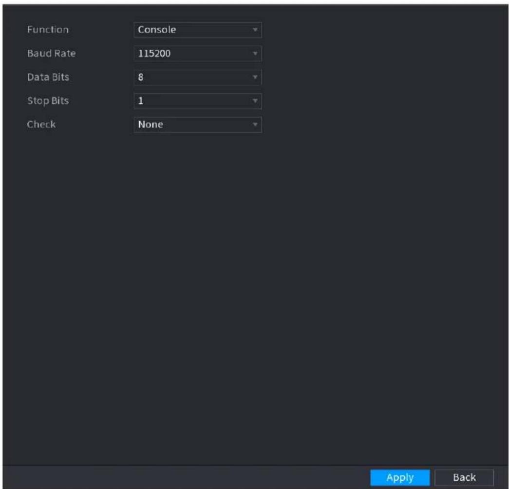
text_image
Function Console Baud Rate 115200 Data Bits 8 Stop Bits 1 Check None Apply BackStep 2 Configure parameters. See Table 4-66.
Step 3 Click Apply.
Table 4-66
| Parameter | Description |
| Function | Select serial port control protocol. Console: Upgrade the program and debug with the console and mini terminal software. Keyboard: Control this Device with special keyboard. Adapter: Connect with PC directly for transparent transmission of data. Protocol COM: Configure the function to protocol COM, in order to overlay card number. PTZ Matrix: Connect matrix control. Different series products support different RS232 functions.The actual product shall prevail. |
| Baud Rate | Select Baud rate, which is 115200 by default. |
| Data Bits | It ranges from 5 to 8, which is 8 by default. |
| Stop Bits | It includes 1 and 2. |
| Parity | It includes none, odd, even, mark and null. |
4.14.3 Security
4.14.3.1 Firewall
Step 1 Select Main Menu > SYSTEM > SECURITY > Firewall.
The Firewall interface is displayed. See Figure 4-236.
Figure 4-236
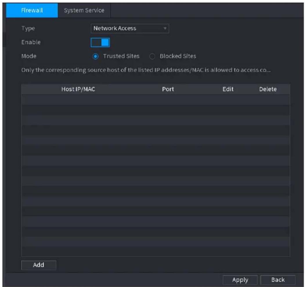
text_image
Firewall System Service Type Network Access Enable Mode Trusted Sites Blocked Sites Only the corresponding source host of the listed IP addresses/MAC is allowed to access co... Host IP/MAC Port Edit Delete Add Apply BackStep 2 Select Enable to enable function in the Type list.
Step 3 Configure the parameters. See Table 4-67.
Table 4-67
| Parameter | Description |
| Type | In the Type list, you can select Network Access, Sync Time-Whitelist, Forbid Ping and Semi Join.Network Access: Configure access right of IP host.Sync Time-Whitelist: Allow designated IP host to synchronize or change Device time. Prevent multiple IP hosts from synchronizing system time with one Device repeatedly.Forbid Ping: The Device does not respond to Ping requests.Semi Join: Protect Device operation from hacker attack. |
| Mode | Mode can be configured when Type is Network Access.If Trusted Sites is enabled, you can visit device port successfully with IP/MAC hosts in Trusted Sites.If Blocked Sites is enabled, you cannot visit device port with IP/MAC hosts in Blocked Sites. |
| Add | When Type is Network Access, you can configure IP Address, IP Segment and MAC Address. |
| IP Address | Enter IP Address, Start Port and End Port that is allowed or forbidden. |
| Start Port | |
| End Port | When Type is IP Address, they can be configured. Start Port and End Port can be configured only in Network Access Type. |
| Start Address | Enter Start Address and End Address of IP Segment. |
| End Address | When Type is IP Segment, they can be configured. |
| MAC Address | Enter MAC Address that is allowed or forbiddenWhen Type is MAC Address, it can be configured. |
Step 4 Click Apply to complete the settings.
4.14.3.2 System Service
You can enable or disable the system internal services.
Step 1 Select Main Menu > SYSTEM > SECURITY > System Service.
The System Service interface is displayed. See Figure 4-237.
Figure 4-237
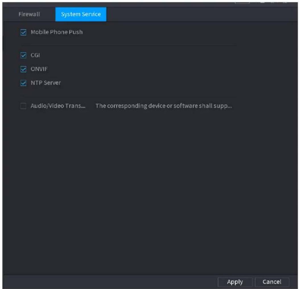
text_image
Firewall System Service ✓ Mobile Phone Push ✓ CGI ✓ ONVIF ✓ NTP Server □ Audio/Video Trans... The corresponding device or software shall supp... Apply CancelStep 2 Select Enable to enable function in the Type list.
Step 3 Configure the parameters. See Table 4-68.
Table 4-68
| Parameter | Description |
| Mobile Phone Push | After enabling this function, the alarm triggered by the NVR can be pushed to the mobile phone. This function is enable by default. |
| CGI | If this function is enabled, the remote devices can be added through the CGI protocol.This function is enabled by default. |
| ONVIF | If this function is enabled, the remote devices can be added through the ONVIF protocol.This function is enabled by default. |
| Audio/Video Transmission | Enable or disable the audio and video stream encryption. If enabled, make sure the devices or software support decryption. |
Step 4 Click Apply to complete the settings.
4.15 Account
You can manage users, user group and ONVIF user, set admin security questions.
- For the user name, the string max length is 31-byte, and for the user group, the string max length is 15-byte. The user name can only contain English letters, numbers and “ ”、“@”、“.”
- The default user amount is 64 and the default group amount is 20. System account adopts two-level management: group and user. The user authorities shall be smaller than group authorities (The admin user authorities are set by default).
- For group or user management, there are two levels: admin and user. The user name shall be unique and one user shall only belong to one group.
4.15.1 User
4.15.1.1 Add User
Step 1 Select Main Menu > ACCOUNT > User.
The User interface is displayed. See Figure 4-238.
Figure 4-238
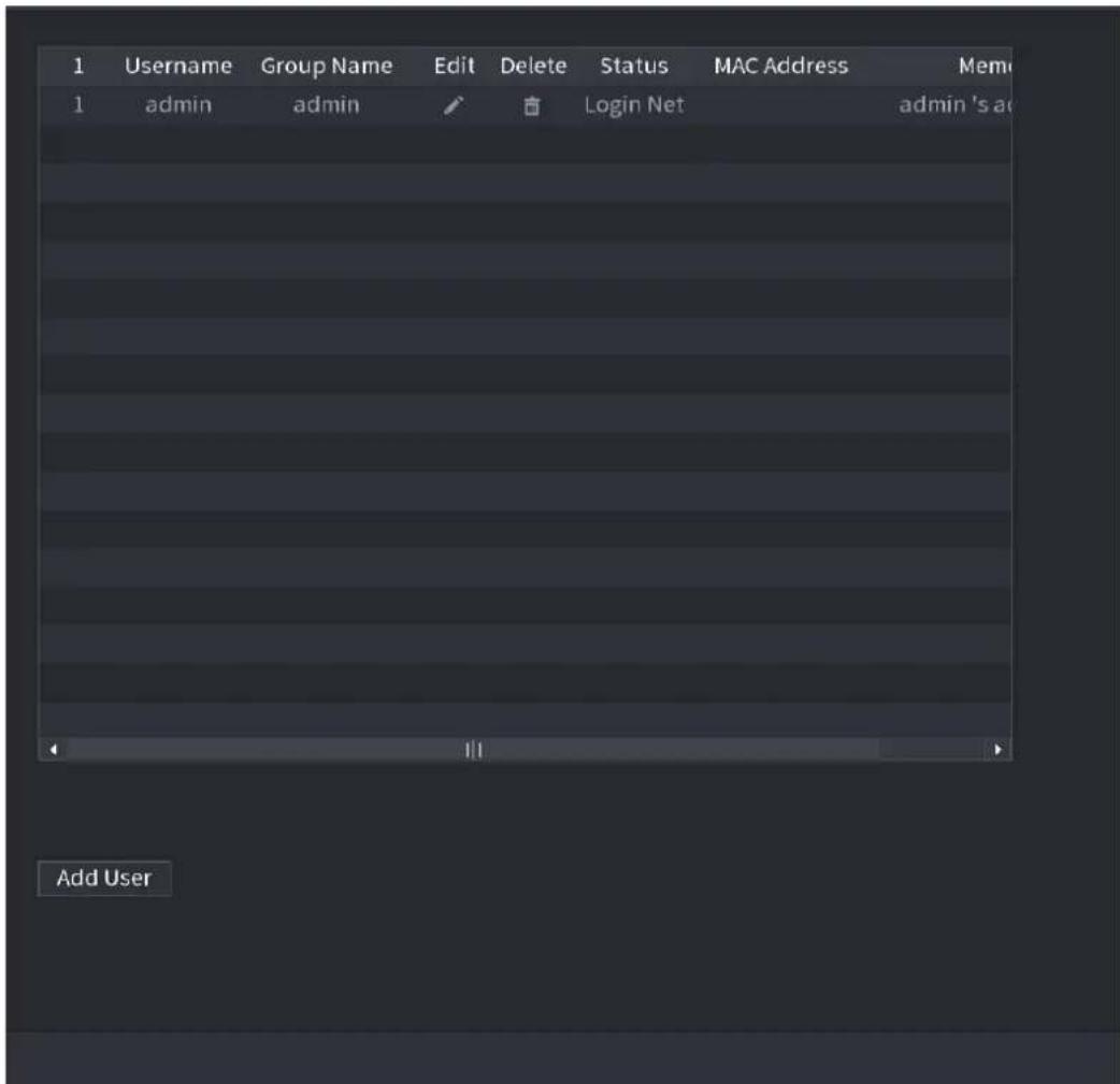
text_image
1 Username Group Name Edit Delete Status MAC Address Mem 1 admin admin Login Net admin 's ac Add UserStep 2 Click Add User button in Figure 4-238.
The Add User interface is displayed. See Figure 4-239.
Figure 4-239
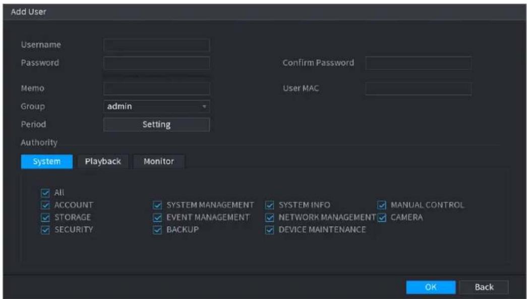
text_image
Add User Username Password Confirm Password Memo Group admin User MAC Period Setting Authority System Playback Monitor All ACCOUNT SYSTEM MANAGEMENT SYSTEM INFO MANUAL CONTROL STORAGE EVENT MANAGEMENT NETWORK MANAGEMENT CAMERA SECURITY BACKUP DEVICE MAINTENANCE OK BackStep 3 Input the user name, password, select the group it belongs to from the dropdown list. Then you can check the corresponding rights for current user. See Table 4-69.
Table 4-69
| Parameter | Description |
| User Name | Enter a user name and password for the account. |
| Password | |
| Confirm Password | Re-enter the password. |
| Memo | Optional.Enter a description of the account. |
| User MAC | Enter user MAC address |
| Group | Select a group for the account.The user rights must be within the group permission. |
| Period | ClickSetto displaySetinterface.Define a period during which the new account can login the device.The new account cannot login the device during the time beyond the set period. |
| Authority | In theAuthorityarea, select the check boxes in theSystemtab,Playbacktab, andMonitortab.To manage the user account easily, when defining the user account authority, it is recommended not to give the authority to the common user account higher that the advanced user account. |
Step 4 Click OK button.

Click to modify the corresponding user information, click to delete the user.
4.15.1.2 Modify Password
Step 1 Select Main Menu > ACCOUNT > User, click of the corresponding user. The Modify User interface is displayed. See Figure 4-240.
Figure 4-240
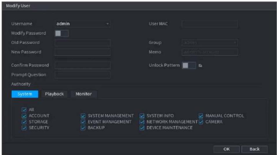
text_image
Modify User Username admin User MAC Modify Password Group Old Password Memo New Password Unlock Pattern Confirm Password Prompt Question Authority System Playback Monitor All SYSTEM MANAGEMENT SYSTEM INFO MANUAL CONTROL ACCOUNT STORAGE EVENT MANAGEMENT NETWORK MANAGEMENT CAMERA SECURITY BACKUP DEVICE MAINTENANCE OK BackStep 2 Check the box to enable Modify Password function. Enter old password and then enter new password twice.

- Password/confirm password: The password ranges from 8 to 32 digitals. It can contain letters, numbers and special characters (excluding “”, “”, “”, “”, “&”). The password shall contain at least two categories. Usually we recommend the strong password.
- For the user of account authority, it can modify the password of other user.
- STRONG PASSWORD RECOMMENDED-For your device own safety, create a strong password of your own choosing. We also recommend you change your password periodically especially in the high security system.
- Check the box to enable Unlock Pattern function, click

Step 3 Enter the Unlock Pattern interface to set. See Figure 4-241.
Figure 4-241
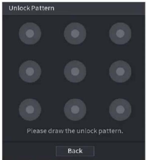
text_image
Unlock Pattern Please draw the unlock pattern. BackStep 4 Click Back.
4.15.2 Group
Step 1 Select Main Menu > ACCOUNT > Group.
The Group interface is displayed. See Figure 4-242.
Figure 4-242
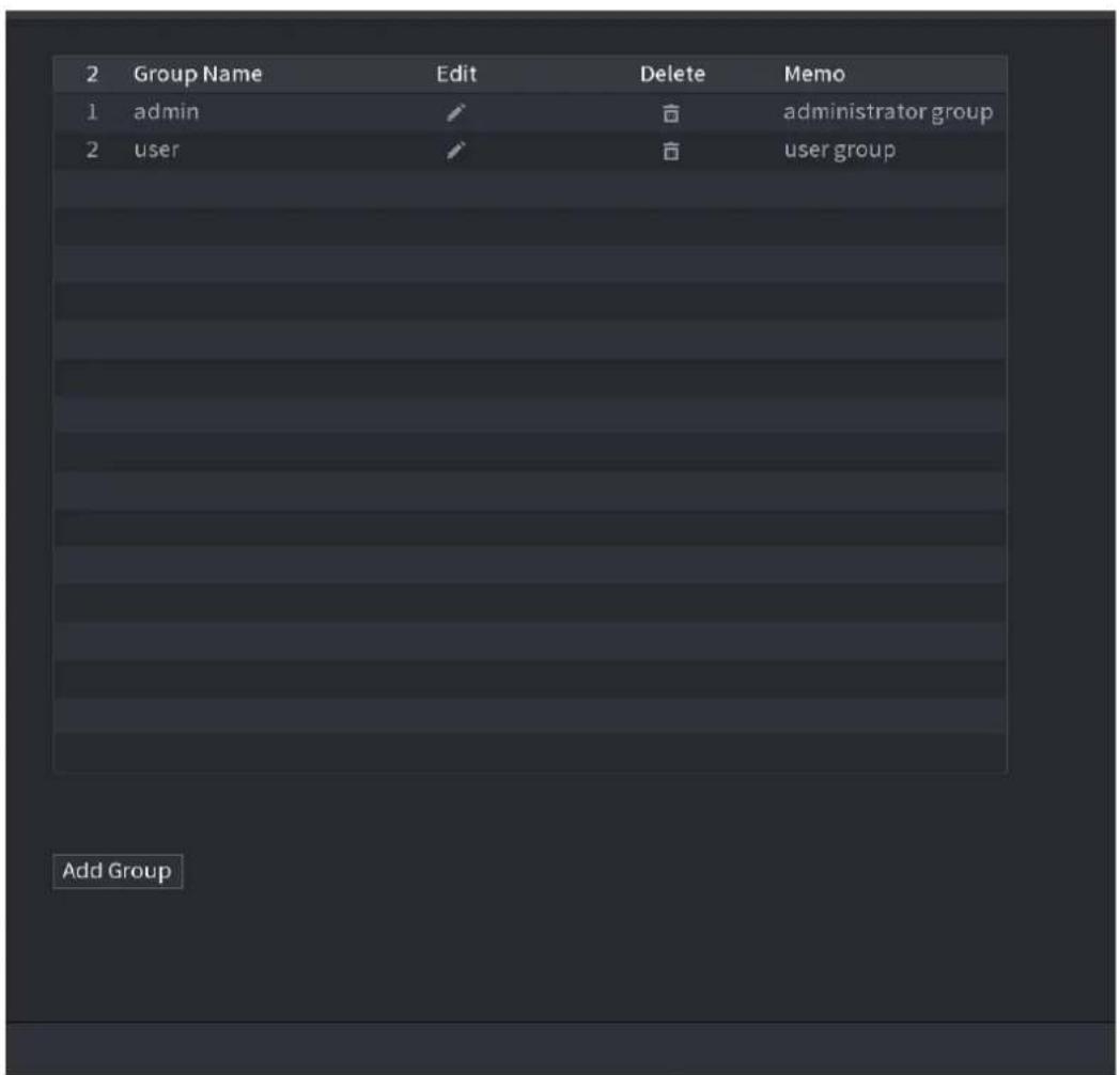
text_image
2 Group Name Edit Delete Memo 1 admin ✓ ✓ administrator group 2 user ✓ ✓ user group Add GroupStep 2 Click Add Group button in Figure 4-242.
The Add Group interface is displayed. See Figure 4-243.
Step 3 Enter group name and then input some memo information if necessary. Check the box to select authorities.
Figure 4-243
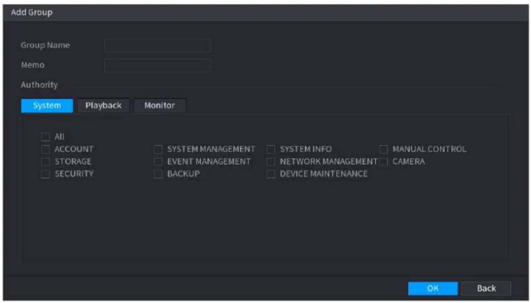
text_image
Add Group Group Name Memo Authority System Playback Monitor All ACCOUNT SYSTEM MANAGEMENT SYSTEM INFO MANUAL CONTROL STORAGE EVENT MANAGEMENT NETWORK MANAGEMENT CAMERA SECURITYBACKUP DEVICE MAINTENANCE OK BackStep 4 Click OK.

Click 📋 to modify the corresponding group information, click 🔒 to delete the group.
4.15.3 Reset Password
You can set security questions and answers. After you successfully answered security questions, you can reset admin account password.

This function is for admin user only.
Step 1 Select Main Menu > ACCOUNT > PASSWORD RESET.
The PASSWORD RESET interface is displayed. See Figure 4-244.
Figure 4-244
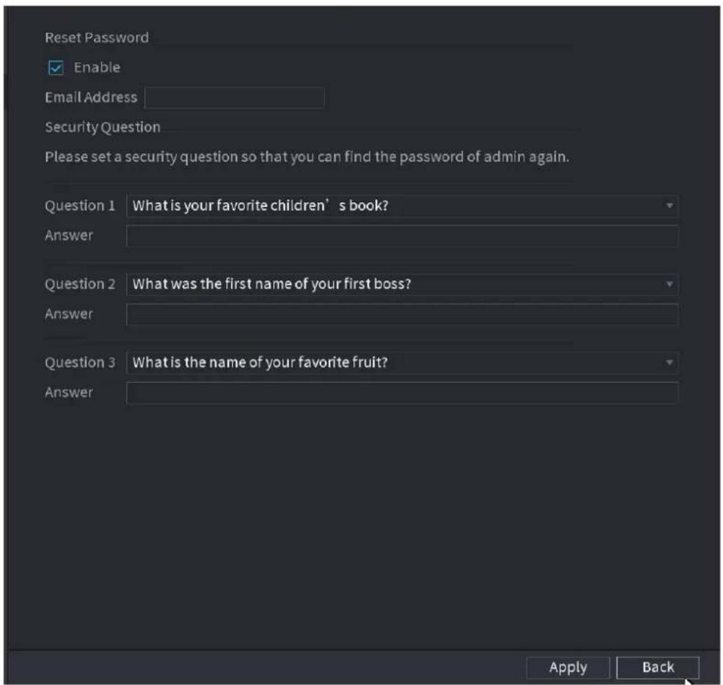
text_image
Reset Password Enable Email Address Security Question Please set a security question so that you can find the password of admin again. Question 1 What is your favorite children' s book? Answer Question 2 What was the first name of your first boss? Answer Question 3 What is the name of your favorite fruit? Answer Apply BackStep 2 Check the box to enable Reset password function.

This function is enabled by default.
Step 3 Input proper security questions and answers.
Step 4 Click OK.
After you successfully set security questions, you can answer the security questions to reset admin password.
4.15.4 ONVIF User
When the camera from the third party is connected with the NVR via the ONVIF user, use the verified ONVIF account to connect to the NVR. Here you can add/delete/modify user

- The default ONVIF user is admin. It is created after you initialize the NVR.
- For some series product, the ONVIF user password is modified when you are initializing the admin password.
Step 1 Select Main Menu > ACCOUNT > ONVIF User.
The ONVIF User interface is displayed. See Figure 4-245.
Figure 4-245
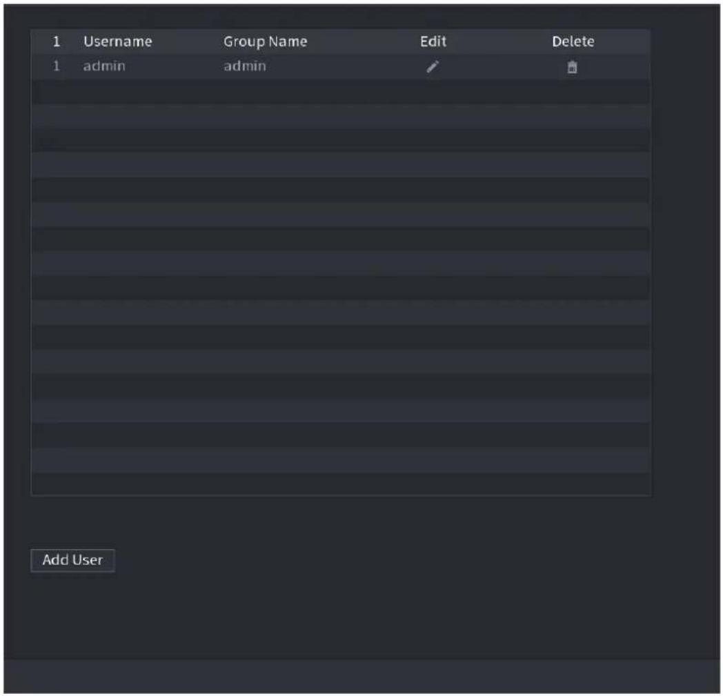
text_image
1 Username Group Name Edit Delete 1 admin admin Add UserStep 2 Click Add User button.
The Add User interface is displayed. See Figure 4-246.
Figure 4-246
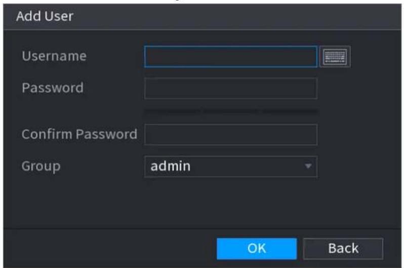
text_image
Add User Username Password Confirm Password Group admin OK BackStep 3 Set user name, password and then select group from the dropdown list.
Step 4 Click OK to complete setup.

4.16 Output and Display
4.16.1 Display
You can configure the display effect such as displaying time title and channel title, adjusting image transparency, and selecting the resolution.
Step 1 Select Main Menu > DISPLAY > Display.
The Display interface is displayed. See Figure 4-247.
Figure 4-247
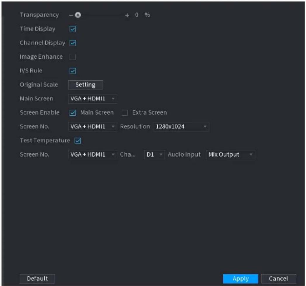
text_image
Transparency Time Display Channel Display Image Enhance IVS Rule Original Scale Setting Main Screen VGA + HDMI1 Screen Enable Main Screen Extra Screen Screen No. VGA + HDMI1 Resolution 1280x1024 Test Temperature Screen No. VGA + HDMI1 Cha... D1 Audio Input Mix Output Default Apply CancelStep 2 Configure the settings for the display parameters. See Table 4-70.
Step 3 Click Apply.
Table 4-70
| Parameter | Description |
| Transparency | Set the transparency of the local menu of the NVR device. The higher the transparency, the more transparent the local menu. |
| Time Display/Channel Display | Select the check box and the date and time of the system will be displayed in the preview screen. |
| Image Enhance | Select the check box to optimize the preview image edges. |
| IVS Rule | Select the check box to display the IVS rules in the preview interface.This function is for some series products only. |
| Original Scale | Click Setting and select the channel to restore the corresponding channel image to the original scale. |
| Main Screen | Select VGA+HDMI1 or HDMI2.Different devices display different contents. See the actual situation. |
| Screen Enable | Select the check box to enable this screen. The image can only b displayed when the screen is enabled. |
| Test Temperature | Check the box to test the object temperature, including trace the high/low temperature. |
| Resolution | Support 1920×1080, 1280×1024(default), 1280×720. |
| Screen No. | Enter the screen number you want to set the audio input. |
| Channel | Select the channel number. |
| Audio Input | Select from audio 1, audio 2 and mix output. |
4.16.2 Tour
You can configure a tour of selected channels to repeat playing videos. The videos display in turn according to the channel group configured in tour settings. The system displays one channel group for a certain period and then automatically changes to the next channel group.
Step 1 Select Main Menu > DISPLAY > Tour.
The Tour interface is displayed. See Figure 4-248.
Figure 4-248
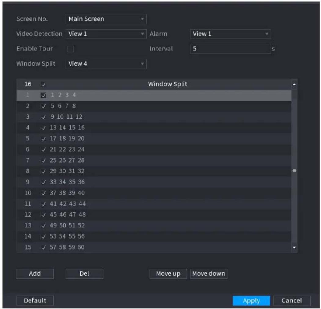
text_image
Screen No. Main Screen Video Detection View 1 Alarm View 1 Enable Tour Interval 5 s Window Split View 4 16 Window Split 1 1 2 3 4 2 5 6 7 8 3 9 10 11 12 4 13 14 15 16 5 17 18 19 20 6 21 22 23 24 7 25 26 27 28 8 29 30 31 32 9 33 34 35 36 10 37 38 39 40 11 41 42 43 44 12 45 46 47 48 13 49 50 51 52 14 53 54 55 56 15 57 58 59 60 Add Del Move up Move down Default Apply Cancel
On the top right of the live view screen, use the left mouse button or press Shift to switch
between (image switching is allowed) and (image switching is not allowed) to turn
on/off the tour function.
On the navigation bar, click to enable the tour and click to disable it.
Step 2 Configure the settings for the tour parameters. See Table 4-71.
Step 3 Click Apply to save the settings.
Table 4-71
| Parameter | Description |
| Enable | Enable tour function. |
| Interval (Sec.) | Enter the amount of time that you want each channel group displays on the screen. The value ranges from 5 seconds to 120 seconds, and the default value is 5 seconds. |
| Video Detect, Alarm | Select the View 1 or View 8 for Motion Detect tour and Alarm Tour (system alarm events). |
| Window Split | In the Window Split list, select View 1, View 4, View 8, or other modes that are supported by the Device. |
| Channel Group | Display all channel groups under the current Window Split setting.Add a channel group: Click Add, in the pop-up Add Group channel, select the channels to form a group, and then click Save.Delete a channel group: Select the check box of any channel group, and then click Delete.Edit a channel group: Select the check box of any channel group and then click Modify, or double-click on the group. The Modify Channel Group dialog box is displayed. You can regroup the channels.Click Move up or Move down to adjust the position of channel group. |
4.16.3 Customized Display
You can set customized video split mode.

- This function is for some series products. Refer to the actual product for detailed information.
● Device max. supports 5 customized videos.
Step 1 Select Main Menu > DISPLAY > Custom Split.
The Custom Split interface is displayed. See Figure 4-249.
Figure 4-249
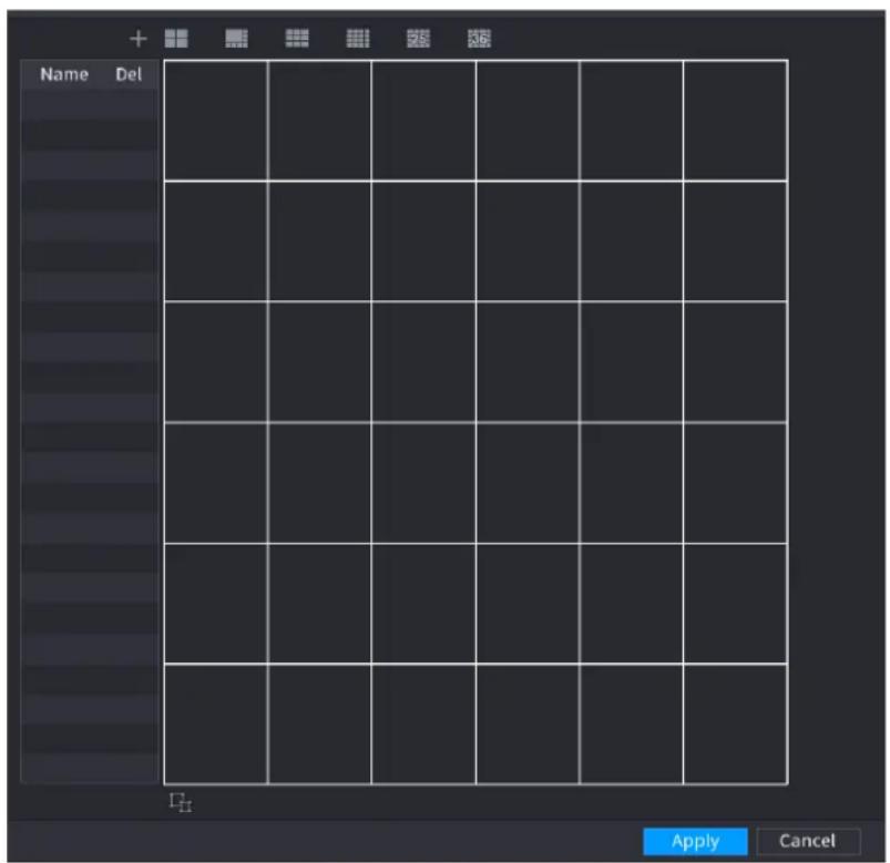
text_image
Name Del Apply CancelStep 2 Click and then click

System adopts the basic window mode as the new window name. For example, if you select the 8 display mode, the default name is Split8.
In regular mode, drag the mouse in the preview frame; you can merge several small windows to one window so that you can get you desired split mode. See Figure 4-250.

- After merge the window, system adopts the remaining window amount as the new name such as Split6.
- Select the window you want to merge (red highlighted), click to cancel the merge to restore the basic mode.
- Click to delete the customized window mode.
Figure 4-250
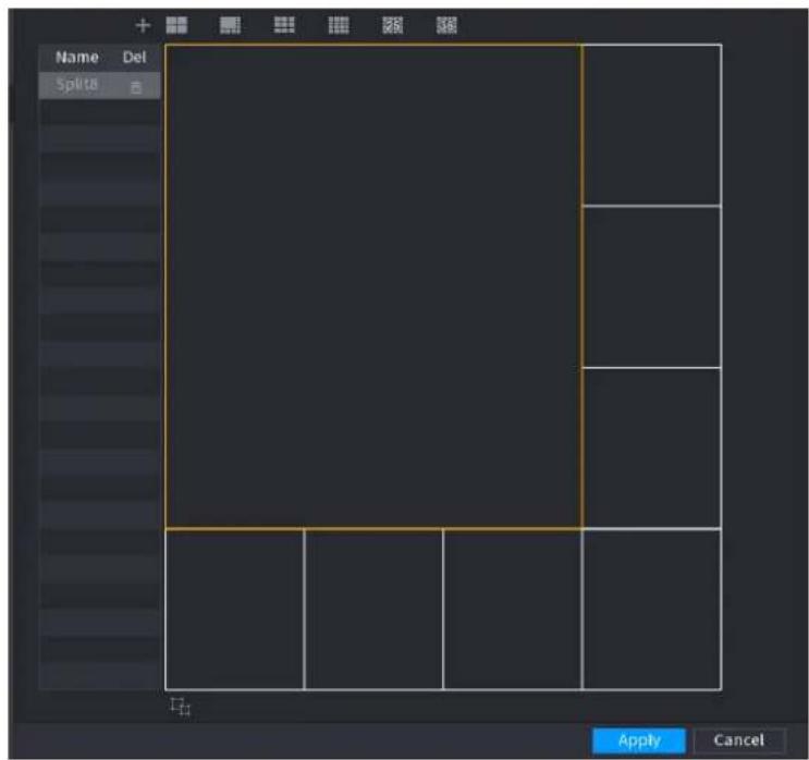
text_image
Name Del Splits Apply CancelStep 3 Click Apply to exit.
After the setup, you can go to the preview window, right click mouse and then select Custom Split. See Figure 4-251.
Figure 4-251
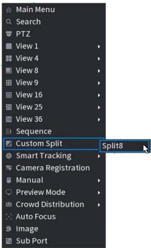
text_image
Main Menu Search PTZ View 1 View 4 View 8 View 9 View 16 View 25 View 36 Sequence Custom Split Split8 Smart Tracking Camera Registration Manual Preview Mode Crowd Distribution Auto Focus Image Sub Port4.17 Audio
The audio function is to manage audio files and set schedule play function. It is to realize audio broadcast activation function.

This function is for some series product only.
4.17.1 File Manage
You can add audio files, listen to audio files, rename and delete audio files, and configure the audio volume.
Step 1 Select Main Menu > AUDIO > File Manager.
The File Manager interface is displayed. See Figure 4-252.
Figure 4-252
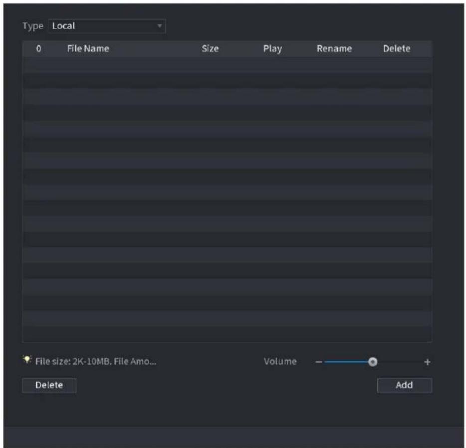
text_image
Type Local 0 File Name Size Play Rename Delete File size: 2K-10MB, File Amo... Volume + Delete AddStep 2 Click Add.
The Add interface is displayed. See Figure 4-253.

NVR supports USB port to import audio file only.
Figure 4-253
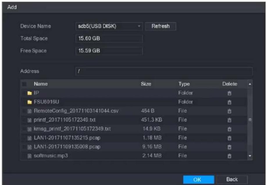
text_image
Add Device Name sdb5(USB DISK) Refresh Total Space 15.60 GB Free Space 15.59 GB Address // Name Size Type Delete IP Folder FSU6016U Folder RemoteConfig_20171103141044.csv 464 B File printf_20171105172349.txt 451.3 KB File kmsg_printf_20171105172349.txt 14.9 KB File LAN1-20171107135215.pcap 1.18 MB File LAN1-20171109135008.pcap 9.16 MB File softmusic.mp3 2.14 MB File OK BackStep 3 Select the audio file and then click Import.
System supports MP3 and PCM audio format.
Step 4 Click OK to start importing audio files from the USB storage device.
If the importing is successful, the audio files will display in the File Manager interface.
4.17.2 Schedule
You can configure the settings to play the audio files during the defined time period.
Step 1 Select Main Menu > AUDIO > Schedule.
The Schedule interface is displayed. See Figure 4-254.
Figure 4-254

text_image
Period File Name Interval Repeat Output 00 : 00 - 24 : 00 None 60 Min. 0 Mic 00 : 00 - 24 : 00 None 60 Min. 0 Mic 00 : 00 - 24 : 00 None 60 Min. 0 Mic 00 : 00 - 24 : 00 None 60 Min. 0 Mic 00 : 00 - 24 : 00 None 90 Min. 0 Mic 00 : 00 - 24 : 00 None 60 Min. 0 Mic Apply BackStep 2 Configure the settings for the schedule parameters. See Table 4-72.
Table 4-72
| Parameter | Description |
| Period | In the Period box, enter the time. Select the check box to enable the settings.You can configure up to six periods. |
| File Name | In the File Name list, select the audio file that you want to play for this configured period. |
| Interval | In the Interval box, enter the time in minutes for how often you want to repeat the playing. |
| Repeat | Configure how many times you want to repeat the playing in thedefined period. |
| Output | Includes two options: MIC and Audio. It is MIC by default. The MIC function shares the same port with talkback function and the latter has the priority. Some series products do not have audio port. The actual product shall prevail. |

- The finish time for audio playing depends on audio file size and the configured interval.
- Playing priority: Alarm event > Audio talk > Trial listening > Schedule audio file.
Step 3 Click Apply to complete the settings.
4.17.3 Broadcast
System can broadcast to the camera, or broadcast to a channel group.
Step 1 Select Mani Menu > AUDIO > BROADCAST.
The BROADCAST interface is displayed. See Figure 4-255.
Figure 4-255
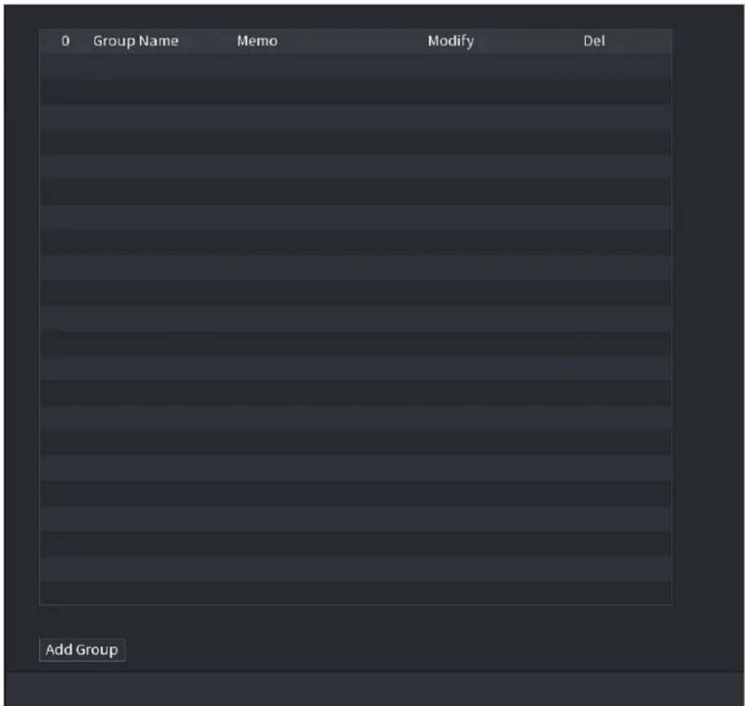
text_image
0 Group Name Memo Modify Del Add GroupStep 2 Click Add Group.
The Add Group interface is displayed. See Figure 4-256.
Figure 4-256
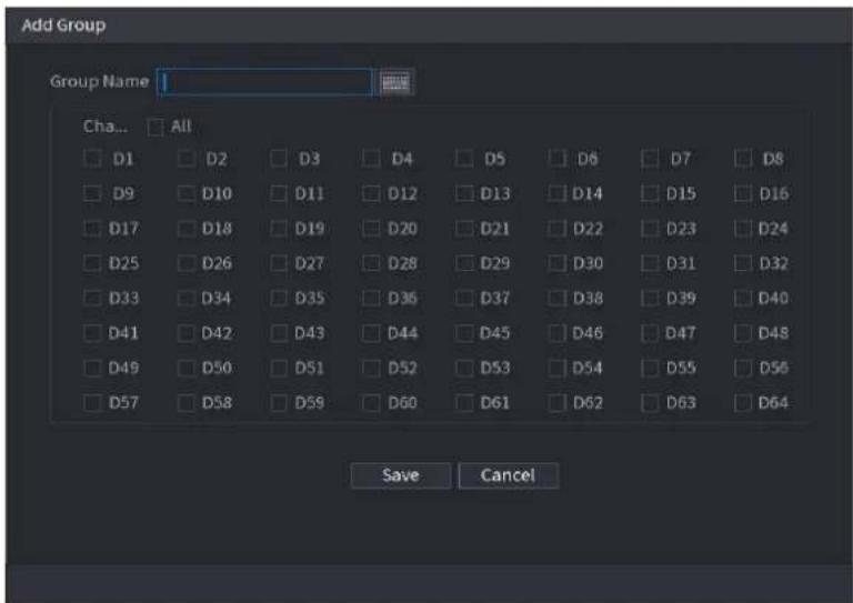
text_image
Add Group Group Name 1 Ch... All D1 D2 D3 D4 D5 D6 D7 D8 D9 D10 D11 D12 D13 D14 D15 D16 D17 D18 D19 D20 D21 D22 D23 D24 D25 D26 D27 D28 D29 D30 D31 D32 D33 D34 D35 D36 D37 D38 D39 D40 D41 D42 D43 D44 D45 D46 D47 D48 D49 D50 D51 D52 D53 D54 D55 D56 D57 D58 D59 D60 D61 D62 D63 D64 Save CancelStep 3 Input group name and select one or more channels.
Step 4 Click Save button to complete broadcast group setup.

- On the broadcast interface, click to change group setup, click to delete group.
- After complete broadcast setup, on the preview interface and then click on the navigation bar, device pops up broadcast dialogue box. Select a group name and then click to begin broadcast. See Figure 4-257.
Figure 4-257
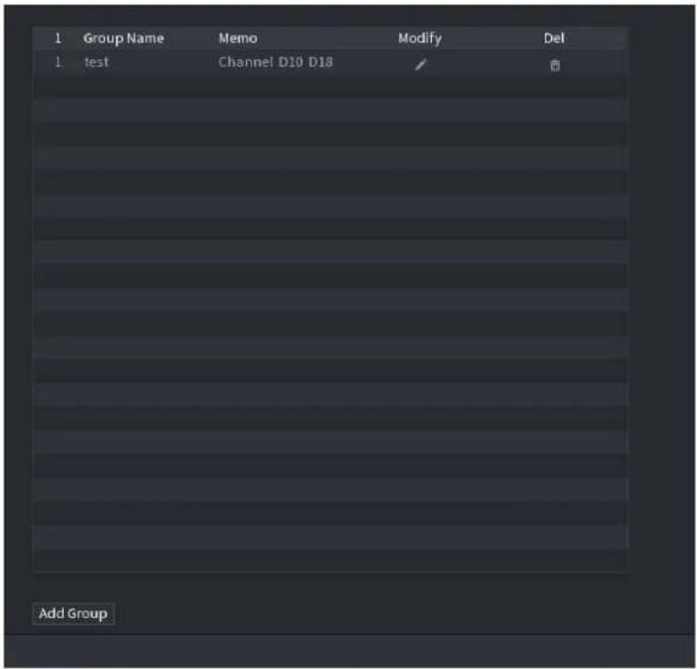
text_image
1 Group Name Memo Modify Del 1 test Channel D10 D18 Add Group4.18 USB Device Auto Pop-up
After you inserted the USB device, system can auto detect it and pop up the following dialogue box. It allows you to conveniently backup file, log, configuration or update system. See Figure 4-258.
Refer to "4.17.1 File Manage", "4.10.1 Log", "4.10.4.2 IMP/EXP", and "4.10.4.4 System Update" for detailed information.
Figure 4-258
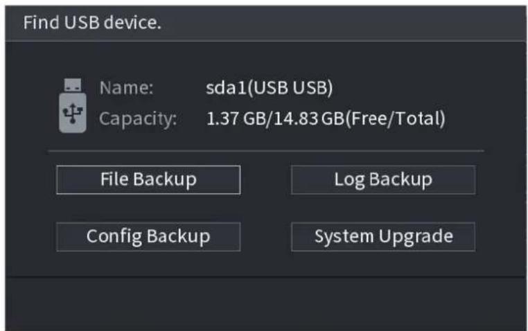
text_image
Find USB device. Name: sda1(USB USB) Capacity: 1.37 GB/14.83 GB(Free/Total) File Backup Log Backup Config Backup System Upgrade4.19 Shutdown

- When you see corresponding dialogue box "System is shutting down..." Do not click power on-off button directly.
- Do not unplug the power cable or click power on-off button to shutdown device directly when device is running (especially when it is recording.)
- Shut down the device and then unplug the power cable before you replace the HDD.
Operations
● From the main menu (Recommended)
Step 1 Click at the top right corner. See Figure 4-259.
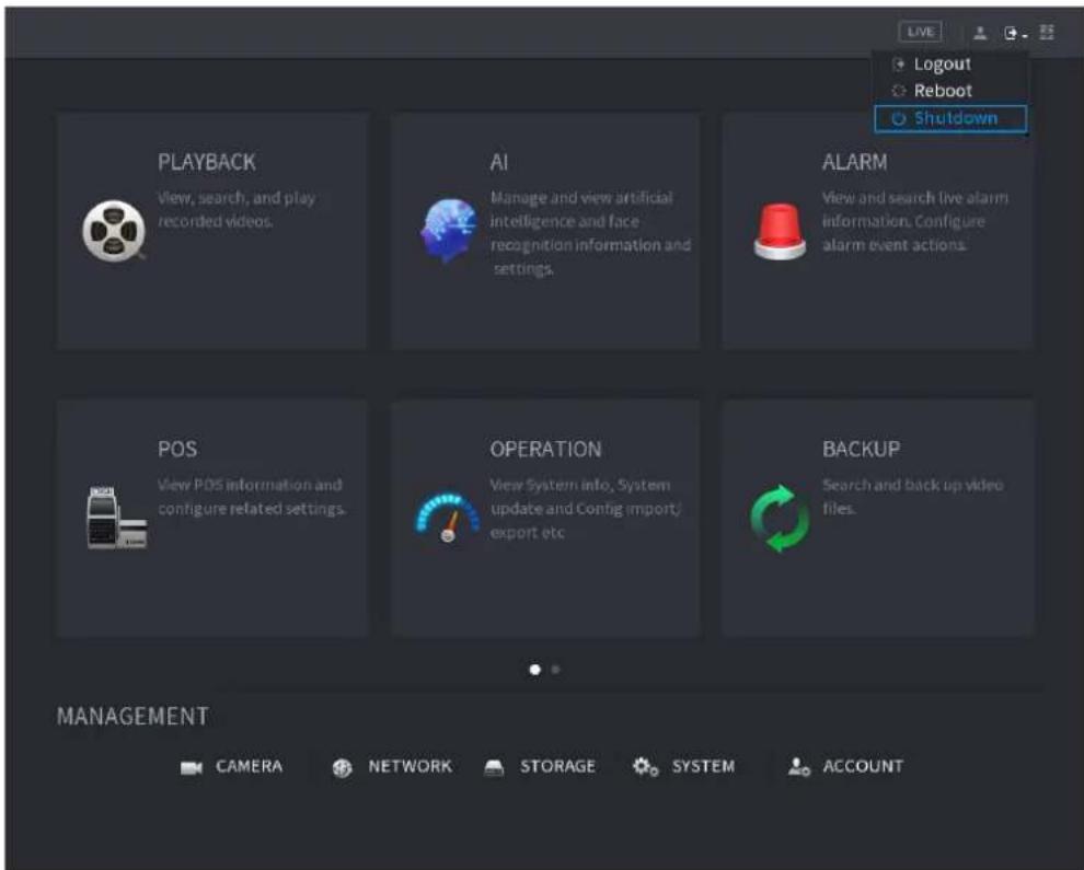
text_image
PLAYBACK View, search, and play recorded videos. AI Manage and view artificial intelligence and face recognition information and settings. ALARM View and search live alarm information. Configure alarm event actions. POS View POS information and configure related settings. OPERATION View System info, System update and Config (import/ export etc. BACKUP Search and back up video files. MANAGEMENT CAMERA NETWORK STORAGE SYSTEM ACCOUNTFigure 4-259
Step 2 Select Shutdown.
Draw the unlock pattern or input password first if you have no authority to shut down. See Figure 4-260 or Figure 4-261.
Figure 4-260
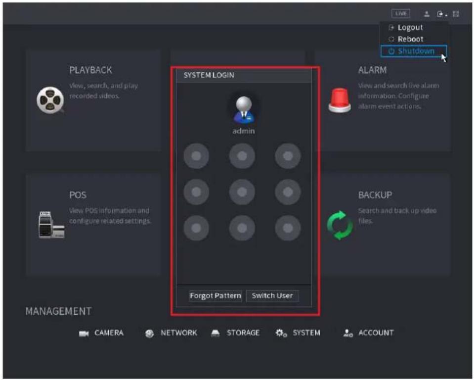
text_image
SYSTEM LOGIN admin ALARM View and search live alarm information. Configure alarm event actions. POS View POS information and configure related settings. BACKUP Search and back up video files. Forgot Pattern Switch User MANAGEMENT CAMERA NETWORK STORAGE SYSTEM ACCOUNT LIVE Logout Reboot ShutdownFigure 4-261
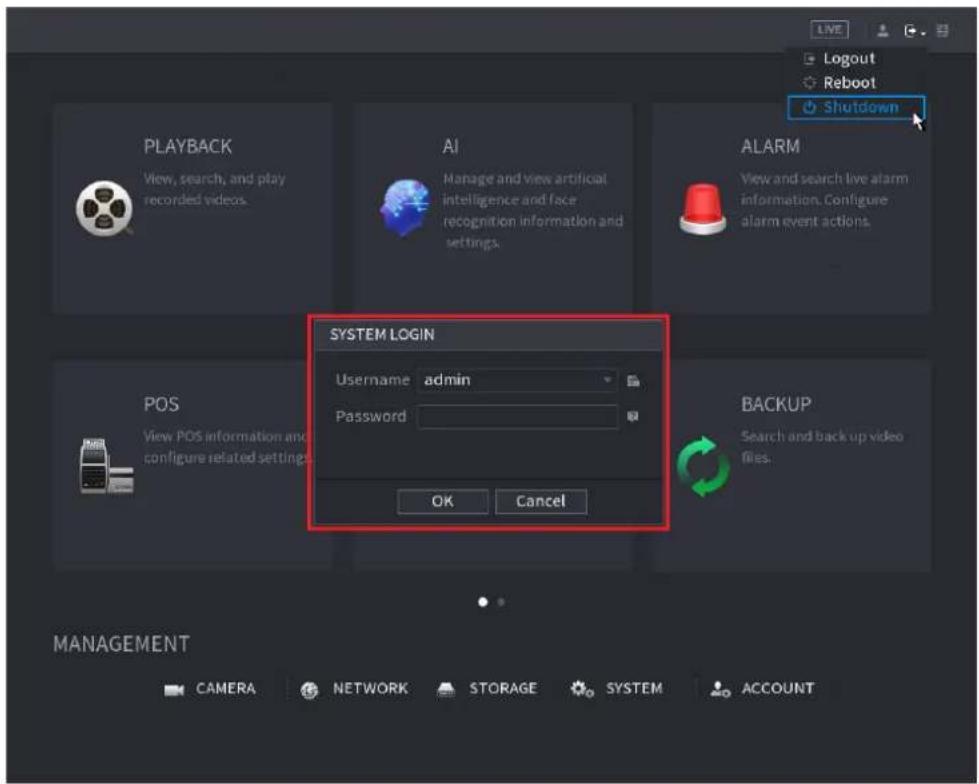
text_image
PLAYBACK View, search, and play recorded videos. AI Manage and view artificial intelligence and face recognition information and settings. ALARM View and search live alarm information. Configure alarm event actions. SYSTEM LOGIN Username admin Password OK Cancel BACKUP Search and back up video files. MANAGEMENT CAMERA NETWORK STORAGE SYSTEM ACCOUNT- Remote Control
Press the power button on the remote for at least 3 seconds.
- Press the power button at the rear panel of the device.
Auto Resume after Power Failure
The system can automatically backup video file and resume previous working status after power failure.

- The interfaces in the Manual are used for introducing the operations and only for reference. The actual interface might be different dependent on the model you purchased. If there is inconsistency between the Manual and the actual product, the actual product shall govern.
- The Manual is a general document for introducing the product, so there might be some functions described for the Device in the Manual not apply to the model you purchased.
- Besides Web, you can use our Smart PSS to login the device. For detailed information, refer to Smart PSS user's manual.
5.1 Network Connection

- The factory default IP of the Device is 192.168.1.108.
- The Device supports monitoring on different browsers such as Safari, Firefox, Google to perform the functions such as multi-channel monitoring, PTZ control, and device parameters configurations.
Step 1 Check to make sure the Device has connected to the network.
Step 2 Configure the IP address, subnet mask and gateway for the PC and the Device. For details about network configuration of the Device, refer to "4.12 Network".
Step 3 On your PC, check the network connection of the Device by using "ping ***.***.***.***". Usually the return value of TTL is 255.
5.2 Web Login
Step 1 Open the browser, enter the IP address of the Device, and then press Enter. The Login in dialog box is displayed. See Figure 5-1.
Figure 5-1
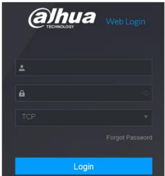
text_image
@Jhua TECHNOLOGY Web Login TCP Forgot Password LoginStep 2 Enter the user name and password.

- The default administrator account is admin. The password is the one that was configured during initial settings. To security your account, it is recommended to keep the password properly and change it regularly.
- Click to display the password.
- If you forget the password, click Forgot Password to reset the password. For details about resetting the password, refer to "5.3 Reset Password".
Step 3 Click Login.
5.3 Reset Password
You can reset the password by the following methods when you forget the password for admin account.
- If the password reset function is enabled, you can use mobile phone to scan the QR code on the local interface or web interface to reset the password.
- If the password reset function is disabled, the system prompts indicating password resetting function is disabled. To reset the password, try either of the following ways:
◇ Login the web with other user account to enable the password reset function.
- Go to local interface to reset the password. For details, refer to "4.1.3 Reset Password".
Step 1 Login the Web of the Device.
The Login in dialog box is displayed. See Figure 5-2.
Figure 5-2
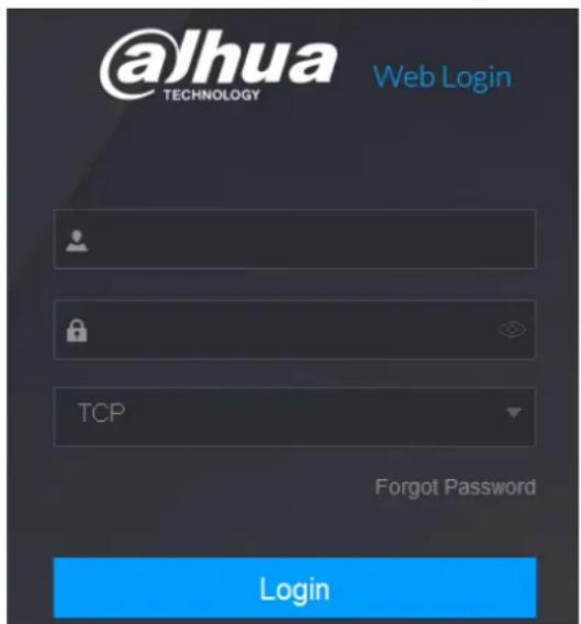
text_image
@lhua TECHNOLOGY Web Login TCP Forgot Password LoginStep 2 Click Forgot Password.
The Reset Password interface is displayed. See Figure 5-3.
Figure 5-3
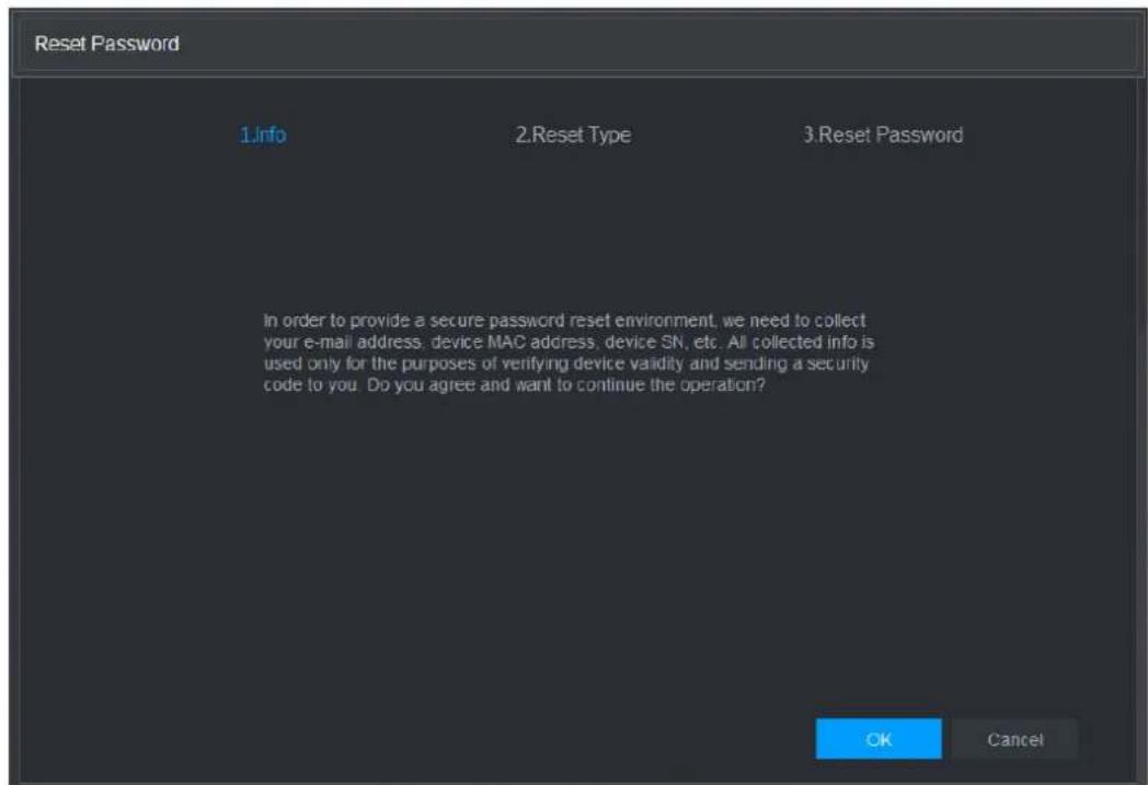
text_image
Reset Password 1.Info 2.Reset Type 3.Reset Password In order to provide a secure password reset environment, we need to collect your e-mail address. device MAC address. device SN, etc. All collected info is used only for the purposes of verifying device validity and sending a security code to you. Do you agree and want to continue the operation? OK CancelStep 3 Click OK.
The reset type interface is displayed. See Figure 5-4.
Figure 5-4
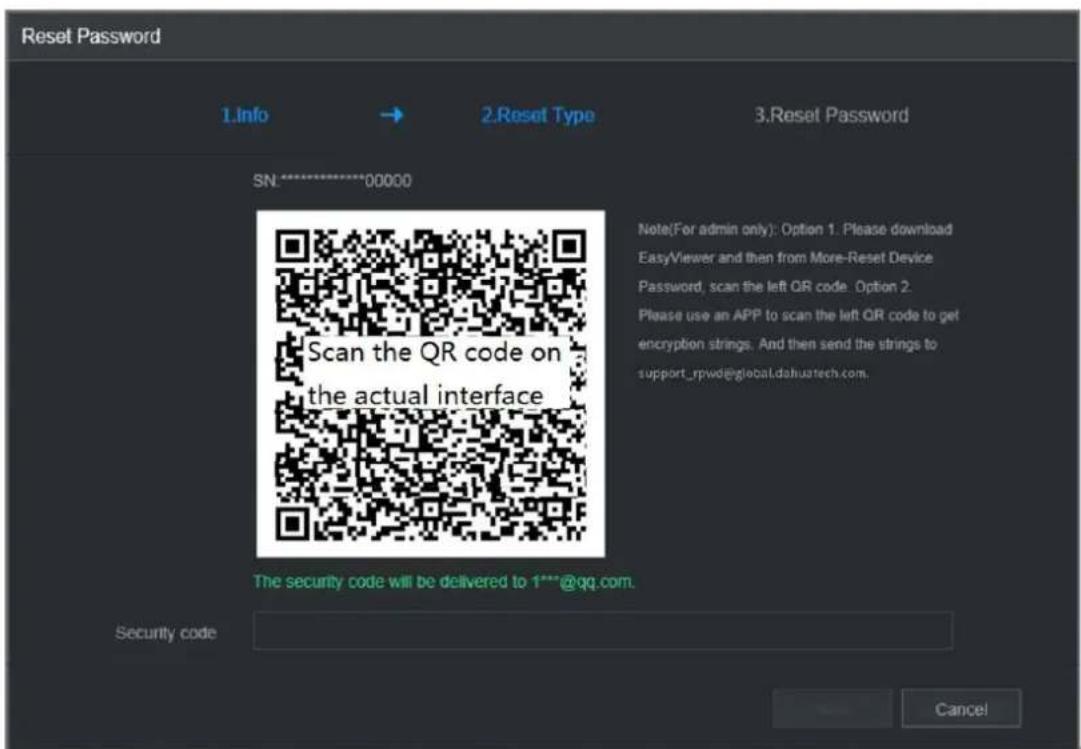
text_image
Reset Password 1.Info → 2.Reset Type 3.Reset Password SN:********00000 Scan the QR code on the actual interface Note(For admin only): Option 1. Please download EasyViewer and then from More-Reset Device Password, scan the left QR code. Option 2. Please use an APP to scan the left QR code to get encryption strings. And then send the strings to support_rpwde@global.dahuatech.com. The security code will be delivered to 1***@qq.com. Security code CancelStep 4 Follow the onscreen instructions to scan the QR code and get the security code.

- You can get the security code twice by scanning the same QR code. If you need to get the security code once again, refresh the interface.
- Use the security code received in your email box to reset the password within 24 hours; otherwise the security code becomes invalid.
- Wrong security code entrance up to five times will cause the security code locked for five minutes. After five minutes, you can continue to use this security code.
Step 5 In the Security code box, enter the security code received in your reserved email box.
Step 6 Click Next.
The new password resetting interface is displayed. See Figure 5-5.
Figure 5-5
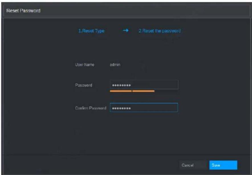
text_image
Reset Password 1.Reset Type → 2.Reset the password User Name admin Password Confirm Password Cancel SaveStep 7 In the Password box, enter the new password and enter it again in the Confirm Password box.

The new password can be set from 8 characters through 32 characters and contains at least two types from number, letter and special characters (excluding", "", "; ", "; " and "&").
Step 8 Click Save. The password resetting is started.
After resetting is completed, a pop-up message is displayed to indicate the result and you will see the login interface is displayed. Then you can use the new password to login the web.
5.4 Web Main Menu
After you have logged in the Web, the main menu is displayed. See Figure 5-6.
For detailed operations, you can refer to "4 Local Basic Operation".
Figure 5-6

text_image
MANAGEMENT 2000-01-01 05:31:03 Saturday 1 2 3 4 5 6 LIVE View all the video PLAYBACK View touch, and play content video. AI Manage and write active configuration and store registration with data and settings. ALARM View all switch the alert information. Configure alarm and video. POS View FOS information with integer timer settings. OPERATION View System info. System spifter and Linky supervised PC.Table 5-1
| No. | Icon | Description |
| 1 |  | ● Includes configuration menu through which you can configure camera settings, network settings, storage settings, system settings, account settings, and view information. |
| 2 | None | Displays system date and time. |
| 3 |  | When you point to , the current user account is displayed. |
| 4 |  | ● Click , select Logout, Reboot, or Shutdown according to your actual situation. |
| 5 |  | Displays Cell Phone Client and Device SN QR Code.● Cell Phone Client: Use your mobile phone to scan the QR code to add the device into the Cell Phone Client, and then you can start accessing the Device from your cell phone.● Device SN: Obtain the Device SN by scanning the QR code. Go to the P2P management platform and add the Device SN into the platform. Then you can access and manage the device in the WAN. For details, refer to the P2P operation manual. You can also configure P2P function in the local configurations, refer to "4.1.4.3 P2P". |
| 6 |  | Displays the web main menu. |
| 7 | None | Includes eight function tiles: LIVE, PLAYBACK, AI, ALARM, POS, OPERATION, BACKUP, DISPLAY, and AUDIO. Click each tile to open the configuration interface of the tile.LIVE: You can perform the operations such as viewing real-time video, configuring channel layout, setting PTZ controls, and using smart talk and instant record functions if needed.PLAYBACK: Search for and play back the recorded video saved on the Device.ALARM: Search for alarm information and configure alarm event actions.AI: Configure and manage artificial intelligent events. It includes smart search, parameters, and database.POS: View POS information and configure related settings.OPERATION: View system information, import/export system configuration files, or update system.BACKUP: Search and back up the video files to the local PC or external storage device such as USB storage device.DISPLAY: Configure the display effect such as displaying content, image transparency, and resolution, and enable the zero-channel function.AUDIO: Manage audio files and configure the playing schedule. The audio file can be played in response to an alarm event if the voice prompts function is enabled. |
- DHCP: DHCP (Dynamic Host Configuration Protocol) is a network protocol. It is one of the TCP/IP protocol cluster. It is principally used to assign temporary IP addresses to computers on a network.
- DDNS: DDNS (Dynamic Domain Name Server) is a service that maps Internet domain names to IP addresses. This service is useful to anyone who wants to operate a server (web server, mail server, ftp server and etc) connected to the internet with a dynamic IP or to someone who wants to connect to an office computer or server from a remote location with software.
- eSATA: eSATA(External Serial AT) is an interface that provides fast data transfer for external storage devices. It is the extension specifications of a SATA interface.
● GPS: GPS (Global Positioning System) is a satellite system, protected by the US military, safely orbiting thousands of kilometers above the earth. - PPPoE: PPPoE (Point to Point Protocol over Ethernet) is a specification for connecting multiple computer users on an Ethernet local area network to a remote site. Now the popular mode is ADSL and it adopts PPPoE protocol.
- Wi-Fi: Wi-Fi is the name of a popular wireless networking technology that uses radio waves to provide wireless high-speed Internet and network connections. The standard is for wireless local area networks (WLANs). It is like a common language that all the devices use to communicate to each other. It is actually IEEE802.11, a family of standard The IEEE (Institute of Electrical and Electronics Engineers Inc.)
- 3G: 3G is the wireless network standard. It is called 3G because it is the third generation of cellular telecom standards. 3G is a faster network for phone and data transmission and speed Is over several hundred kbps. Now there are four standards: CDMA2000, WCDMA, TD-SCDMA and WiMAX.
- Dual-stream: The dual-stream technology adopts high-rate bit stream for local HD storage such as QCIF/CIF/2CIF/DCIF/4CIF encode and one low-rate bit stream for network transmission such as QCIF/CIF encode. It can balance the local storage and remote network transmission. The dual-stream can meet the difference band width requirements of the local transmission and the remote transmission. In this way, the local transmission using high-bit stream can achieve HD storage and the network transmission adopting low bit stream suitable for the fluency requirements of the 3G network such as WCDMA, EVDO, TD-SCDMA..
- On-off value: It is the non-consecutive signal sampling and output. It includes remote sampling and remote output. It has two statuses: 1/0.
| Questions | Solutions |
| NVR cannot boot up properly. | Input power is not correct.Power connection is not correct.Power switch button is damaged.Program upgrade is wrong.HDD malfunction or something wrong with HDD ribbon.Seagate DB35.1, DB35.2, SV35 or Maxtor 17-g has compatibility problem. Please upgrade to the latest version to solve this problem.Front panel error.Main board is damaged. |
| NVR often automatically shuts down or stops running. | Input voltage is not stable or it is too low.HDD malfunction or something wrong with the ribbon.Button power is not enough.Front video signal is not stable.Working environment is too harsh, too much dust.Hardware malfunction. |
| System cannot detect hard disk. | HDD is broken.HDD ribbon is damaged.HDD cable connection is loose.Main board SATA port is broken. |
| There is no video output whether it is one-channel, multiple-channel or all-channel output. | Program is not compatible. Please upgrade to the latest version.Brightness is 0. Please restore factory default setup.Check your screen saver.NVR hardware malfunctions. |
| I cannot search local records. | HDD ribbon is damaged.HDD is broken.Upgraded program is not compatible.The recorded file has been overwritten.Record function has been disabled. |
| Video is distorted when searching local records. | Video quality setup is too low.Program read error, bit data is too small. There is mosaic in the full screen. Please restart the NVR to solve this problem.HDD data ribbon error.HDD malfunction.NVR hardware malfunctions. |
| Time display is not correct. | Setup is not correctBattery contact is not correct or voltage is too low.Crystal is broken. |
| NVR cannot control PTZ. | Front panel PTZ errorPTZ decoder setup, connection or installation is not correct.Cable connection is not correct.PTZ setup is not correct.PTZ decoder and NVR protocol is not compatible.PTZ decoder and NVR address is not compatible.When there are several decoders, please add 120 Ohm between the PTZ decoder A/B cables furthest end to delete the reverberation or impedance matching. Otherwise the PTZ control is not stable.The distance is too far. |
| I cannot log in client-end or web. | For Windows 98 or Windows ME user, please update your system to Windows 2000 sp4. Or you can install client-end software of lower version. Please note right now, our NVR is not compatible with Windows VISTA control.ActiveX control has been disabled.No dx8.1 or higher. Please upgrade display card driver.Network connection error.Network setup error.Password or user name is invalid.Client-end is not compatible with NVR program. |
| There is only mosaic no video when preview or playback video file remotely. | Network fluency is not good.Client-end resources are limit.Current user has no right to monitor. |
| Network connection is not stable. | Network is not stable.IP address conflict.MAC address conflict.PC or device network card is not good. |
| Burn error /USB back error. | Burner and NVR are in the same data cable.System uses too much CPU resources. Please stop record first and then begin backup.Data amount exceeds backup device capacity. It may result in burner error.Backup device is not compatible.Backup device is damaged. |
| Keyboard cannot control NVR. | NVR serial port setup is not correctAddress is not correctWhen there are several switchers, power supply is not enough.Transmission distance is too far. |
| Alarm signal cannot been disarmed. | ● Alarm setup is not correct.● Alarm output has been open manually.● Input device error or connection is not correct.● Some program versions may have this problem. Please upgrade your system. |
| Alarm function is null. | ● Alarm setup is not correct.● Alarm cable connection is not correct.● Alarm input signal is not correct.● There are two loops connect to one alarm device. |
| Record storage period is not enough. | ● Camera quality is too low. Lens is dirty. Camera is installed against the light. Camera aperture setup is not correct.● HDD capacity is not enough.● HDD is damaged. |
| Cannot playback the downloaded file. | ● There is no media player.● No DXB8.1 or higher graphic acceleration software.● There is no DivX503Bundle.exe control when you play the file transformed to AVI via media player.● No DivX503Bundle.exe or ffdshow-2004 1012 .exe in Windows XP OS. |
| Forgot local menu operation password or network password | ● Please contact your local service engineer or our sales person for help. We can guide you to solve this problem. |
| There is no video. The screen is in black. | ● IPC IP address is not right.● IPC port number is not right.● IPC account (user name/password) is not right.● IPC is offline. |
| The displayed video is not full in the monitor. | Please cheek current resolution setup. If the current setup is 1920*1080, then you need to set the monitor resolution as 1920*1080. |
| There is no HDMI output. | ● Displayer is not in HDMI mode.● HDMI cable connection is not right. |
| The video is not fluent when I view in multiple-channel mode from the client-end. | ● The network bandwidth is not sufficient. The multiple-channel monitor operation needs at least 100M or higher.● Your PC resources are not sufficient. For 16-ch remote monitor operation, the PC shall have the following environment:Quad Core, 2G or higher memory, independent displayer, display card memory 256M or higher. |
| I can not connect to the IPC | Please make sure the IPC has booted up.IPC network connection is right and it is onlineIPC IP is in the blacklist.The device has connected to the too many IPC. It cannot transmit the video.Check the IPC port value and the time zone is the same as the NVR.Make sure current network environment is stable. |
| After I set the NVR resolution as 1080P, my monitor can not display. | Shut down the device and then reboot. When you reboot, please press the Fn button at the same time and then release after 5 seconds. You can restore NVR resolution to the default setup. |
| My admin account has been changed and I can not log in. | Use telnet and then input the following command:cd /mnt/mtd/Config/rm -rf grouprm -rf passwordReboot the device to restore the default password. |
| After I login the Web , I can not find the remote interface to add the IPC. | Please clear the Web controls and load again. |
| There is IP and gateway, I can access the internet via the router. But I can not access the internet after I reboot the NVR. | Please use command PING to check you can connect to the gateway or not. Use telnet to access and then use command "ifconfig -a" to check device IP address. If you see the subnet mask and the gateway has changed after the reboot. Please upgrade the applications and set again. |
| I use the VGA monitor.I want to know if I use the multiple-window mode, I see the video from the main stream or the sub stream? | For 32-channel series product, the 9/16-window is using the sub stream.For 4/8/16 series product, system is using the main stream no matter you are in what display mode. |
Daily Maintenance
- Please use the brush to clean the board, socket connector and the chassis regularly.
- The device shall be soundly earthed in case there is audio/video disturbance. Keep the device away from the static voltage or induced voltage.
- Please unplug the power cable before you remove the audio/video signal cable, RS232 or RS485 cable.
- Do not connect the TV to the local video output port (VOUT). It may result in video output circuit.
● Always shut down the device properly. Please use the shutdown function in the menu, or you can press the power button in the rear pane for at least three seconds to shut down the device.
Otherwise it may result in HDD malfunction.
- Please make sure the device is away from the direct sunlight or other heating sources. Please keep the sound ventilation.
- Please check and maintain the device regularly.
Appendix 1 Cybersecurity Recommendations
Cybersecurity is more than just a buzzword: it's something that pertains to every device that is connected to the internet. IP video surveillance is not immune to cyber risks, but taking basic steps toward protecting and strengthening networks and networked appliances will make them less susceptible to attacks. Below are some tips and recommendations on how to create a more secured security system.
Mandatory actions to be taken for basic equipment network security:
1. Use Strong Passwords
Please refer to the following suggestions to set passwords:
- The length should not be less than 8 characters;
- Include at least two types of characters; character types include upper and lower case letters, numbers and symbols;
- Do not contain the account name or the account name in reverse order;
- Do not use continuous characters, such as 123, abc, etc.;
- Do not use overlapped characters, such as 111, aaa, etc.;
2. Update Firmware and Client Software in Time
- According to the standard procedure in Tech-industry, we recommend to keep your equipment (such as NVR, DVR, IP camera, etc.) firmware up-to-date to ensure the system is equipped with the latest security patches and fixes. When the equipment is connected to the public network, it is recommended to enable the “auto-check for updates” function to obtain timely information of firmware updates released by the manufacturer.
• We suggest that you download and use the latest version of client software.
“Nice to have” recommendations to improve your equipment network security:
1. Physical Protection
We suggest that you perform physical protection to equipment, especially storage devices. For example, place the equipment in a special computer room and cabinet, and implement well-done access control permission and key management to prevent unauthorized personnel from carrying out physical contacts such as damaging hardware, unauthorized connection of removable equipment (such as USB flash disk, serial port), etc.
2. Change Passwords Regularly
We suggest that you change passwords regularly to reduce the risk of being guessed or cracked.
3. Set and Update Passwords Reset Information Timely
The equipment supports password reset function. Please set up related information for password reset in time, including the end user's mailbox and password protection questions. If the information changes, please modify it in time. When setting password protection questions, it is suggested not to use those that can be easily guessed.
4. Enable Account Lock
The account lock feature is enabled by default, and we recommend you to keep it on to guarantee the account security. If an attacker attempts to log in with the wrong password several times, the corresponding account and the source IP address will be locked.
5. Change Default HTTP and Other Service Ports
We suggest you to change default HTTP and other service ports into any set of numbers between 1024\~65535, reducing the risk of outsiders being able to guess which ports you are using.
6. Enable HTTPS
We suggest you to enable HTTPS, so that you visit Web service through a secure communication channel.
7. Enable Whitelist
We suggest you to enable whitelist function to prevent everyone, except those with specified IP addresses, from accessing the system. Therefore, please be sure to add your computer's IP address and the accompanying equipment's IP address to the whitelist.
8. MAC Address Binding
We recommend you to bind the IP and MAC address of the gateway to the equipment, thus reducing the risk of ARP spoofing.
9. Assign Accounts and Privileges Reasonably
According to business and management requirements, reasonably add users and assign a minimum set of permissions to them.
10. Disable Unnecessary Services and Choose Secure Modes
If not needed, it is recommended to turn off some services such as SNMP, SMTP, UPnP, etc., to reduce risks.
If necessary, it is highly recommended that you use safe modes, including but not limited to the following services:
- SNMP: Choose SNMP v3, and set up strong encryption passwords and authentication passwords.
- SMTP: Choose TLS to access mailbox server.
- FTP: Choose SFTP, and set up strong passwords.
- AP hotspot: Choose WPA2-PSK encryption mode, and set up strong passwords.
11. Audio and Video Encrypted Transmission
If your audio and video data contents are very important or sensitive, we recommend that you use encrypted transmission function, to reduce the risk of audio and video data being stolen during transmission.
Reminder: encrypted transmission will cause some loss in transmission efficiency.
12. Secure Auditing
- Check online users: we suggest that you check online users regularly to see if the device is logged in without authorization.
- Check equipment log: By viewing the logs, you can know the IP addresses that were used to log in to your devices and their key operations.
13. Network Log
Due to the limited storage capacity of the equipment, the stored log is limited. If you need to save the log for a long time, it is recommended that you enable the network log function to ensure that the critical logs are synchronized to the network log server for tracing.
14. Construct a Safe Network Environment
In order to better ensure the safety of equipment and reduce potential cyber risks, we recommend:
- Disable the port mapping function of the router to avoid direct access to the intranet devices from external network.
- The network should be partitioned and isolated according to the actual network needs. If there are no communication requirements between two sub networks, it is suggested to use VLAN, network GAP and other technologies to partition the network, so as to achieve the network isolation effect.
- Establish the 802.1x access authentication system to reduce the risk of unauthorized access to private networks.
Calculate total capacity needed by each device according to video recording (video recording type and video file storage time).
Step 1: According to Formula (1) to calculate storage capacity q_i that is the capacity of each channel needed for each hour, unit Mbyte.
$$ q _ {i} \quad d _ {i} \quad 1 0 2 4: \tag {1} $$
In the formula: d_i means the bit rate, unit Kbit/s
Step 2: After video time requirement is confirmed, according to Formula (2) to calculate the storage capacity m_i , which is storage of each channel needed unit Mbyte.
$$ m _ {i} = q _ {i} \times h _ {i} \times D _ {i} \tag {2} $$
In the formula:
h_i means the recording time for each day (hour)
D_i means number of days for which the video shall be kept
Step 3: According to Formula (3) to calculate total capacity (accumulation) q_T that is needed for all channels in the device during scheduled video recording.
$$ q _ {T} = \sum_ {i = 1} ^ {c} m _ {i} \tag {3} $$
In the formula: c means total number of channels in one device
Step 4: According to Formula (4) to calculate total capacity (accumulation) q_T that is needed for all channels in device during alarm video recording (including motion detection).
$$ q _ {T} = \sum_ {i = 1} ^ {c} m _ {i} \times a \% \tag{4} $$
In the formula: a% means alarm occurrence rate
Appendix 3 Compatible Network Camera List
Please note all the models in the following list for reference only. For those products not included in the list, please contact your local retailer or technical supporting engineer for detailed information.
| Manufacture | Model | Version | Video Encode | Audio/Video | Protocol |
| AXIS | P1346 | 5.40.9.2 | H264 | √ | ONVIF/Private |
| P3344/P3344-E | 5.40.9.2 | H264 | √ | ONVIF/Private | |
| P5512 | — | H264 | √ | ONVIF/Private | |
| Q1604 | 5.40.3.2 | H264 | √ | ONVIF/Private | |
| Q1604-E | 5.40.9 | H264 | √ | ONVIF/Private | |
| Q6034E | — | H264 | √ | ONVIF/Private | |
| Q6035 | 5.40.9 | H264 | √ | ONVIF/Private | |
| Q1755 | — | H264 | √ | ONVIF/Private | |
| M7001 | — | H264 | √ | Private | |
| M3204 | 5.40.9.2 | H264 | √ | Private | |
| P3367 | HEAD LFP4_0 130220 | H264 | √ | ONVIF | |
| P5532-P | HEAD LFP4_0 130220 | H264 | √ | ONVIF | |
| ACTi | ACM-3511 | A1D-220-V3.12 .15-AC | MPEG4 | √ | Private |
| ACM-8221 | A1D-220-V3.13 .16-AC | MPEG4 | √ | Private | |
| Arecont | AV1115 | 65246 | H264 | √ | Private |
| AV10005DN | 65197 | H264 | √ | Private | |
| AV2115DN | 65246 | H264 | √ | Private | |
| AV2515DN | 65199 | H264 | √ | Private | |
| AV2815 | 65197 | H264 | √ | Private | |
| AV5115DN | 65246 | H264 | √ | Private | |
| AV8185DN | 65197 | H264 | √ | Private | |
| Bosch | NBN-921-P | — | H264 | √ | ONVIF |
| NBC-455-12P | — | H264 | √ | ONVIF | |
| VG5-825 | 9500453 | H264 | √ | ONVIF | |
| NBN-832 | 66500500 | H264 | √ | ONVIF | |
| VEZ-211-IWT EIVA | — | H264 | √ | ONVIF | |
| NBC-255-P | 15500152 | H264 | √ | ONVIF | |
| VIP-X1XF | — | H264 | √ | ONVIF | |
| Brikcom | B0100 | — | H264 | √ | ONVIF |
| D100 | — | H264 | √ | ONVIF | |
| GE-100-CB | — | H264 | √ | ONVIF | |
| FB-100A | v1.0.3.9 | H264 | √ | ONVIF | |
| FD-100A | v1.0.3.3 | H264 | √ | ONVIF | |
| Cannon | VB-M400 | — | H264 | √ | Private |
| CNB | MPix2.0DIR | XNETM112011 1229 | H264 | √ | ONVIF |
| VIPBL1.3MIR VF | XNETM210011 1229 | H264 | √ | ONVIF | |
| IGC-2050F | XNETM210011 1229 | H264 | √ | ONVIF | |
| CP PLUS | CP-NC9-K | 6.E.2.7776 | H264 | √ | ONVIF/Private |
| CP-NC9W-K | 6.E.2.7776 | H264 | √ | Private | |
| CP-ND10-R | cp20111129AN S | H264 | √ | ONVIF | |
| CP-ND20-R | cp20111129AN S | H264 | √ | ONVIF | |
| CP-NS12W-C R | cp20110808NS | H264 | √ | ONVIF | |
| VS201 | cp20111129NS | H264 | √ | ONVIF | |
| CP-NB20-R | cp20110808BN S | H264 | √ | ONVIF | |
| CP-NT20VL3-R | cp20110808BN S | H264 | √ | ONVIF | |
| CP-NS36W-A R | cp20110808NS | H264 | √ | ONVIF | |
| CP-ND20VL2-R | cp20110808BN S | H264 | √ | ONVIF | |
| CP-RNP-1820 | cp20120821NS A | H264 | √ | Private | |
| CP-RNC-TP2 0FL3C | cp20120821NS A | H264 | √ | Private | |
| CP-RNP-12D | cp20120828AN S | H264 | √ | Private | |
| CP-RNC-DV1 0 | cp20120821NS A | H264 | √ | Private | |
| CP-RNC-DP2 0FL2C | cp20120821NS A | H264 | √ | Private | |
| Dynacolor | ICS-13 | d20120214NS | H264 | √ | ONVIF/Private |
| ICS-20W | vt20111123NSA | H264 | √ | ONVIF/Private | |
| NA222 | — | H264 | √ | ONVIF | |
| MPC-IPVD-03 13 | k20111208ANS | H264 | √ | ONVIF/Private | |
| MPC-IPVD-0313AF | k20111208BNS | H264 | √ | ONVIF/Private | |
| Honeywell | HIDC-1100PT | h.2.2.1824 | H264 | √ | ONVIF |
| HIDC-1100P | h.2.2.1824 | H264 | √ | ONVIF | |
| HIDC-0100P | h.2.2.1824 | H264 | √ | ONVIF | |
| HIDC-1300V | 2.0.0.21 | H264 | √ | ONVIF | |
| HICC-1300W | 2.0.1.7 | H264 | √ | ONVIF | |
| HICC-2300 | 2.0.0.21 | H264 | √ | ONVIF | |
| HDZ20HDX | H20130114NSA | H264 | √ | ONVIF | |
| LG | LW342-FP | — | H264 | √ | Private |
| LNB5100 | — | H264 | √ | ONVIF | |
| Imatek | KNC-B5000 | — | H264 | √ | Private |
| KNC-B5162 | — | H264 | √ | Private | |
| KNC-B2161 | — | H264 | √ | Private | |
| Panasonic | NP240/CH | — | MPEG4 | √ | Private |
| WV-NP502 | — | MPEG4 | √ | Private | |
| WV-SP102H | 1.41 | H264 | √ | ONVIF/Private | |
| WV-SP105H | — | H264 | √ | ONVIF/Private | |
| WV-SP302H | 1.41 | H264、MPEG4 | √ | ONVIF/Private | |
| WV-SP306H | 1.4 | H264、MPEG4 | √ | ONVIF/Private | |
| WV-SP508H | — | H264、MPEG4 | √ | ONVIF/Private | |
| WV-SP509H | — | H264、MPEG4 | √ | ONVIF/Private | |
| WV-SF332H | 1.41 | H264、MPEG4 | √ | ONVIF/Private | |
| WV-SW316H | 1.41 | H264、MPEG4 | √ | ONVIF/Private | |
| WV-SW355H | 1.41 | H264、MPEG4 | √ | ONVIF/Private | |
| WV-SW352H | — | H264、MPEG4 | √ | ONVIF/Private | |
| WV-SW152E | 1.03 | H264、MPEG4 | √ | ONVIF/Private | |
| WV-SW558H | — | H264、MPEG4 | √ | ONVIF/Private | |
| WV-SW559H | — | H264、MPEG4 | √ | ONVIF/Private | |
| WV-SP105H | 1.03 | H264、MPEG4 | √ | ONVIF/Private | |
| WV-SW155E | 1.03 | H264、MPEG4 | √ | ONVIF/Private | |
| WV-SF336H | 1.44 | H264、MPEG4 | √ | ONVIF/Private | |
| WV-SF332H | 1.41 | H264、MPEG4 | √ | ONVIF/Private | |
| WV-SF132E | 1.03 | H264、MPEG4 | √ | ONVIF/Private | |
| WV-SF135E | 1.03 | H264、MPEG4 | √ | ONVIF/Private | |
| WV-SF346H | 1.41 | H264、MPEG4 | √ | ONVIF/Private | |
| WV-SF342H | 1.41 | H264、MPEG4 | √ | ONVIF/Private | |
| WV-SC385H | 1.08 | H264、MPEG4 | √ | ONVIF/Private | |
| WV-SC386H | 1.08 | H264、MPEG4 | √ | ONVIF/Private | |
| WV-SP539 | 1.66 | H264、MPEG4 | √ | ONVIF | |
| DG-SC385 | 1.66 | H264、MPEG4 | √ | ONVIF | |
| PELCO | IXSOLW | 1.8.1-20110912-1.9082-A1.6617 | H264 | √ | Private |
| IDE20DN | 1.7.41.9111-O3.6725 | H264 | √ | Private | |
| D5118 | 1.7.8.9310-A1.5288 | H264 | √ | Private | |
| IM10C10 | 1.6.13.9261-O2.4657 | H264 | √ | Private | |
| DD4N-X | 01.02.0015 | MPEG4 | √ | Private | |
| DD423-X | 01.02.0006 | MPEG4 | √ | Private | |
| D5220 | 1.8.3-FC2-20120614-1.9320-A1.8035 | H264 | √ | Private | |
| Samsung | SNB-3000P | 2.41 | H264、MPEG4 | √ | ONVIF/Private |
| SNP-3120 | 1.22_110120_1 | H264、MPEG4 | √ | ONVIF/Private | |
| SNP-3370 | 1.21_110318 | MPEG4 | √ | Private | |
| SNB-5000 | 2.10_111227 | H264、MPEG4 | √ | ONVIF/Private | |
| SND-5080 | — | H264、MPEG4 | √ | Private | |
| SNZ-5200 | 1.02_110512 | H264、MPEG4 | √ | ONVIF/Private | |
| SNP-5200 | 1.04_110825 | H264、MPEG4 | √ | ONVIF/Private | |
| SNB-7000 | 1.10_110819 | H264 | √ | ONVIF/Private | |
| SNB-6004 | V1.0.0 | H264 | √ | ONVIF | |
| Sony | SNC-DH110 | 1.50.00 | H264 | √ | ONVIF/Private |
| SNC-CH120 | 1.50.00 | H264 | √ | ONVIF/Private | |
| SNC-CH135 | 1.73.01 | H264 | √ | ONVIF/Private | |
| SNC-CH140 | 1.50.00 | H264 | √ | ONVIF/Private | |
| SNC-CH210 | 1.73.00 | H264 | √ | ONVIF/Private | |
| SNC-DH210 | 1.73.00 | H264 | √ | ONVIF/Private | |
| SNC-DH240 | 1.50.00 | H264 | √ | ONVIF/Private | |
| SNC-DH240-T | 1.73.01 | H264 | √ | ONVIF/Private | |
| SNC-CH260 | 1.74.01 | H264 | √ | ONVIF/Private | |
| SNC-CH280 | 1.73.01 | H264 | √ | ONVIF/Private | |
| SNC-RH-124 | 1.73.00 | H264 | √ | ONVIF/Private | |
| SNC-RS46P | 1.73.00 | H264 | √ | ONVIF/Private | |
| SNC-ER550 | 1.74.01 | H264 | √ | ONVIF/Private | |
| SNC-ER580 | 1.74.01 | H264 | √ | ONVIF/Private | |
| SNC-ER580 | 1.78.00 | H264 | √ | ONVIF | |
| SNC-VM631 | 1.4.0 | H264 | √ | ONVIF | |
| WV-SP306 | 1.61.00 | H264、MPEG4 | √ | SDK | |
| WV-SP306 | 1.61.00 | H264 | √ | ONVIF | |
| SNC-VB600 | 1.5.0 | H264 | √ | Private | |
| SNC-VM600 | 1.5.0 | H264 | √ | Private | |
| SNC-VB630 | 1.5.0 | H264 | √ | Private | |
| SNC-VM630 | 1.5.0 | H264 | √ | Private | |
| SANYO | VCC-HDN4000PC | — | H264 | √ | ONVIF |
ZHEJIANG DAHUA VISION TECHNOLOGY CO.,LTD.
Address: No.1199, Bin'an Road, Binjiang District, Hangzhou, P.R. China
Postcode: 310053
Tel: +86-571-87688883
Fax: +86-571-87688815
Email:overseas@dahuatech.com
Website: www.dahuasecurity.com