
TLP-X20U - Projector TOSHIBA - Free user manual and instructions
Find the device manual for free TLP-X20U TOSHIBA in PDF.


| Product Type | 3LCD Data Projector |
| Model | TLP-X20U |
| Dimensions (W x H x D) | Without document camera: 345 x 104 x 281 mm With camera: 345 x 104 x 336 mm |
| Weight | Without camera: 5.3 kg With camera: 6.2 kg |
| Power Consumption | Without camera: 320 W (Standby: 18 W) With camera: 330 W (Standby: 18 W) |
| Lamp Type | High pressure mercury lamp, 210 W |
| Projection Screen Size | 25 to 250 inches |
| Projection Distance | 1.14 to 9.11 m |
| Speaker | 2 W monaural |
| Card Slot | PC Card Standard Type II (for memory cards) |
| Connectors | COMPUTER IN 1 (Mini D-sub 15-pin), COMPUTER IN 2 (DVI), MONITOR OUT, S-VIDEO, VIDEO, AUDIO L/R, AUDIO IN, AUDIO OUT, CONTROL (RS-232C), USB Type B |
| Display Technology | 3-panel LCD, 1.3-inch TFT active matrix, 786,432 pixels x 3 (1024x768) |
| Projection Lens | Zoom lens F=2.2-2.5, f=47-61 mm, manual focus and zoom |
| Document Imaging Camera (optional) | F=3.1, f=6.4 mm, 1/2-inch CCD, LED light, manual focus |
| Accessories Included | Remote control with batteries, power cord, RGB cable, Mac adapter, AV cable, audio cable, control cable, USB cable, manuals |
| Safety Features | Auto power-off, thermal shutdown, lamp cover interlock, security lock slot, ventilation openings |
| Maintenance | Air filter cleaning, lens cleaning, lamp replacement (user-replaceable, model TLPLX10) |
| Warranty | 2 years parts and labor (lamp: 90 days) |
| Ambient Temperature | 0°C to 35°C (operating) |
| Remote Control Range | Approximately 5 m, within 15° angle |
Frequently Asked Questions - TLP-X20U TOSHIBA
User questions about TLP-X20U TOSHIBA
0 question about this device. Answer the ones you know or ask your own.
Ask a new question about this device
Download the instructions for your Projector in PDF format for free! Find your manual TLP-X20U - TOSHIBA and take your electronic device back in hand. On this page are published all the documents necessary for the use of your device. TLP-X20U by TOSHIBA.
USER MANUAL TLP-X20U TOSHIBA
TLP-X10U
SAFETY PRECAUTIONS


The lightning flash with arrowhead symbol, within an equilateral triangle, is intended to alert the user to the presence of uninsulated “dangerous voltage” within the product’s enclosure that may be of sufficient magnitude to constitute a risk of electric shock to persons.

The exclamation point within an equilateral triangle is intended to alert the user to the presence of important operating and maintenance (servicing) instructions in the literature accompanying the appliance.
WARNING: TO REDUCE THE RISK OF FIRE OR ELECTRIC SHOCK, DO NOT EXPOSE THIS APPLIANCE TO RAIN OR MOISTURE. DANGEROUS HIGH VOLTAGES ARE PRESENT INSIDE THE ENCLOSURE. DO NOT OPEN THE CABINET. REFER SERVICING TO QUALIFIED PERSONNEL ONLY.
FCC Radio Frequency Interference Statement
Note: This equipment has been tested and found to comply with the limits for a Class A digital device, pursuant to part 15 of the FCC Rules. These limits are designed to provide reasonable protection against harmful interference when the equipment is operated in a commercial environment. This equipment generates, uses, and can radiates radio frequency energy and, if not installed and used in accordance with the instruction manual, may cause harmful interference to radio communications. Operation of this equipment in a residential area is likely to cause harmful interference in which case the user will be required to correct the interference at his own expense.
WARNING: Changes or modifications made to this equipment, not expressly approved by Toshiba, or parties authorized by Toshiba, could void the user's authority to operate the equipment.
CAUTION: Laser beam is emitted when the laser button of the remote control is pressed. Do not look from the front of the remote control. Do not face toward a person or to a mirror.
IMPORTANT PRECAUTIONS

Save Original Packing Materials
The original shipping carton and packing materials will come in handy if you ever have to ship your LCD projector. For maximum protection, repack the set as it was originally packed at the factory.
Avoid Volatile Liquid
Do not use volatile liquids, such as an insect spray, near the unit. Do not leave rubber or plastic products touching the unit for a long time. They will mar the finish.
Moisture Condensation
Never operate this unit immediately after moving it from a cold location to a warm location. When the unit is exposed to such a change in temperature, moisture may condense on the crucial internal parts. To prevent the unit from possible damage, do not use the unit for at least 2 hours when there is an extreme or sudden change in temperature.
In the spaces provided below, record the Model and Serial No. located at the bottom of your LCD projector.
Model No. ____ Serial No. ____
Retain this information for future reference.
IMPORTANT SAFETY INSTRUCTIONS
CAUTION: PLEASE READ AND OBSERVE ALL WARNINGS AND INSTRUCTIONS GIVEN IN THIS OWNER'S MANUAL AND THOSE MARKED ON THE UNIT. RETAIN THIS BOOKLET FOR FUTURE REFERENCE.
This set has been designed and manufactured to assure personal safety. Improper use can result in electric shock or fire hazard. The safeguards incorporated in this unit will protect you if you observe the following procedures for installation, use and servicing. This unit is fully transistorized and does not contain any parts that can be repaired by the user.
DO NOT REMOVE THE CABINET COVER, OR YOU MAY BE EXPOSED TO DANGEROUS VOLTAGE. REFER SERVICING TO QUALIFIED SERVICE PERSONNEL ONLY.
1. Read Owner's Manual
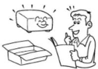
After unpacking this product, read the owner's manual carefully, and follow all the operating and other instructions.
2. Power Sources
This product should be operated only from the type of power source indicated on the marking label. If you are not sure of the type of power supply to your home, consult your product dealer or local power company. For products intended to operate from battery power, or other sources, refer to the operating instructions.

3. Source of Light
Do not look into the lens while the lamp is on. The strong light from the lamp may cause damage to your eyes or sight.

4. Ventilation
Openings in the cabinet are provided for ventilation and to ensure reliable operation of the product and to protect it from overheating, and these openings must not be blocked or covered. The openings should never be blocked by placing the product on a bed, sofa, rug or other similar surface. This product should not be placed in a built-in installation such as a bookcase or rack unless proper ventilation is provided or the manufacturer's instructions have been adhered to.

IMPORTANT SAFETY INSTRUCTIONS (continued)
5
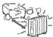
5. Heat
The product should be situated away from heat sources such as radiators, heat registers, stoves, or other products (including amplifiers) that produce heat.
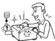
7. Cleaning
Unplug this product from the wall outlet before cleaning. Do not use liquid cleaners or aerosol cleaners. Use a damp cloth for cleaning.
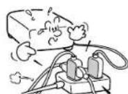
9. Overloading
Do not overload wall outlets; extension cords, or integral convenience receptacles as this can result in a risk of fire or electric shock.
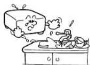
6. Water and Moisture
Do not use this product near water – for example, near a bath tub, wash bowl, kitchen sink, or laundry tub; in a wet basement; or near a swimming pool and the like.
8. Power-Cord Protection
Power-supply cords should be routed so that they are not likely to be walked on or pinched by items placed upon or against them, paying particular attention to cords at plugs, convenience receptacles, and the point where they exit from the product.
10. Lightning
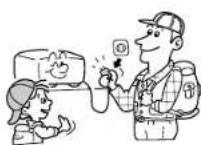
For added protection for this product during storm, or when it is left unattended and unused for long periods of time, unplug it from the wall outlet. This will prevent damage to the product due to lightning and power-line surges.
Continued

IMPORTANT SAFETY INSTRUCTIONS (continued)
6
11. Object and Liquid Entry
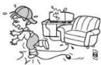
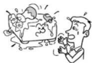
Never push objects of any kind into this product through openings as they may touch dangerous voltage points or short-out parts that could result in a fire or electric shock. Never spill liquid of any kind on the product.
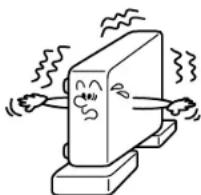
12. Do not place the product vertically
Do not use the product in the upright position to project the pictures at the ceiling, or any other vertical positions. It may fall down and dangerous.
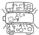
13. Stack Inhibited
Do not stack other equipment on this product or do not place this product on the other equipment.
Top and bottom plates of this product develops heat and may give some undesirable damage to other unit.
14. Attachments
Do not use attachments not recommended by the product manufacturer as they may cause hazards.
15. Accessories
Do not place this product on an unstable cart, stand, tripod, bracket, or table. The product may fall, causing serious injury to a child or adult, and serious damage to the product. Use only with a cart, stand, tripod, bracket, or table recommended by the manufacturer, or sold with the product. Any mounting of the product should follow the manufacturer's instructions, and should use a mounting accessory recommended by the manufacturer.
A product and cart combination should be moved with care. Quick stops, excessive force, and uneven surfaces may cause the product and cart combination to overturn.

IMPORTANT SAFETY INSTRUCTIONS (continued)
- If glass components, including lens and lamp, should break, contact your dealer for repair service.
This product incorporates glass components, including a lens and a lamp. If such parts should break, please handle with care to avoid injury and contact your dealer for repair service. The broken pieces of glass may cause to injury.
In the unlikely event of the lamp rupturing, thoroughly clean the area around the projector and discard any edible items placed in that area.
- Damage Requiring Service
Unplug this product from the wall outlet and refer servicing to qualified service personnel under the following conditions:
a) When the power-supply cord or plug is damaged.
b) If liquid has been spilled, or objects have fallen into the product.
c) If the product has been exposed to rain or water.
d) If the product does not operate normally by following the operating instructions. Adjust only those controls that are covered by the operating instructions as an improper adjustment of other controls may result in damage and will often require extensive work by a qualified technician to restore the product to its normal operation.
e) If the product has been dropped or damaged in any way.
f) When the product exhibits a distinct change in performance – this indicates a need for service.
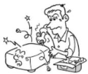
- Servicing
Do not attempt to service this product yourself as opening or removing covers may expose you to dangerous voltage or other hazards. Refer all servicing to qualified service personnel.
- Replacement Parts
When replacement parts are required, be sure the service technician has used replacement parts specified by the manufacturer or have the same characteristics as the original part. Unauthorized substitutions may result in fire, electric shock, or other hazards. (Replacement of the lamp only should be made by users.)
IMPORTANT SAFETY INSTRUCTIONS (continued)
8
20. Safety Check
Upon completion of any service or repairs to this product, ask the service technician to perform safety checks to determine that the product is in proper operating condition.
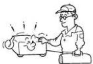
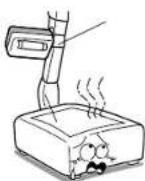
21. Do not get your hands between the camera arm and the main unit when setting the camera arm back in its original position.
To avoid injury, be careful not to get your hands caught when setting the camera arm back in its original position. Families with children should be particularly careful.
22. Do not carry by the camera arm.
Do not carry the projector by the camera arm.
Doing so can result in damage or injury.
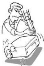
23. Do not leave documents on the unit for long periods of time while using the document imaging function.
Do not leave texts, papers or other documents for projection on the unit for long periods of time. The heat could erase the letters on a thermal paper.
24. Do not move the projector while the arm is still erect.
Always store the arm back in position when moving the projector. Otherwise injury or damage may result.
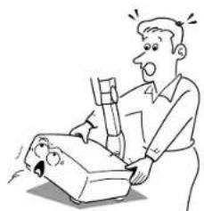
25. Do not look into the arm light while it is lit.
The strong light may cause damage to your eyes or sight.
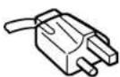
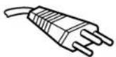
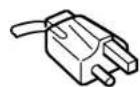
Power supply cord selection
If your line voltage is 220 to 240V, use one of the following types of cable.
Plug
| configuration | Plug type | Line voltage |
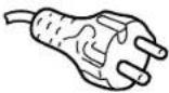 | EURO240V10 – 15A | 220 – 240V |

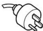
200 - 240V
200 - 240V
200 - 240V
200 - 240V
The Ground Truth image displays a single, solid horizontal line. According to Rule 2 (UNDERSCORE & LINE RULES), this is a stylistic or background line, not a placeholder underscore. Therefore, the OCR result must ignore it and output nothing or only meaningful text. The provided OCR content is "____", which consists of four underscores. This is an incorrect interpretation of the line as a placeholder, violating the rule that stylistic lines must be ignored. The OCR has hallucinated underscores where none should exist based on the GT's visual context. Hence, the OCR result is inconsistent with the Ground Truth.
Contents
Before use
SAFETY PRECAUTIONS 2
IMPORTANT PRECAUTIONS 3
IMPORTANT SAFETY INSTRUCTIONS 4
Power supply cord selection....9
Contents 10
Names of each part on the main unit.... 11
Names of each part on the remote control 14
Loading batteries.... 15
Remote control operation.... 16
Installation and connections
Floor-mounted projector placement.... 17
Projector placement angle adjustment 20
Ceiling-mounted projector placement.... 21
Connecting a computer 22
Connecting a computer with DVI output connector..... 23
Connecting video equipment 24
Projector operation control by a computer.... 26
How to use the output connector 27
Operations
Projection on the screen.... 28
Turning the power off.... 31
Adjusting the picture automatically.... 32
Correcting the keystone distortion.... 33
Cutting off the picture and sound temporarily 34
Freezing the picture 35
Enlarging the picture size.... 36
Displaying PIP Sub-pictures.... 37
Displaying Information.... 38
Operating a computer by the remote control 39
Projecting images stored in a memory card.... 40
Adjustments & Settings
Adjustments and settings on the menu screen.... 45
Operating the menu screen 47
QUICK MENU adjustments and settings 48
FULL MENU adjustments and settings – Picture ...... 54
FULL MENU settings – Audio 60
FULL MENU settings – Keystone 62
FULL MENU settings – Display 64
FULL MENU settings – Default setting 67
FULL MENU settings – Factory reset mode 71
PIP menu setting 73
Document imaging camera
Part names (of the document imaging camera model)... 74
Preparation of the document imaging camera 75
Picture projection with the document imaging camera.. 76
Lock the white balance 79
Correcting illuminated defects....80
Store the camera images into the memory card 81
Maintenance
Trouble indications 82
Air filter cleaning 83
Lens and main unit cleaning 85
Lamp replacement.... 86
Others
Before calling service personal 88
Pin assignment of COMPUTER IN, MONITOR OUT connector ..... 90
Applicable signal 91
Controlling the projector by using RS-232C....93
Specifications 99
LIMITED WARRANTY 101
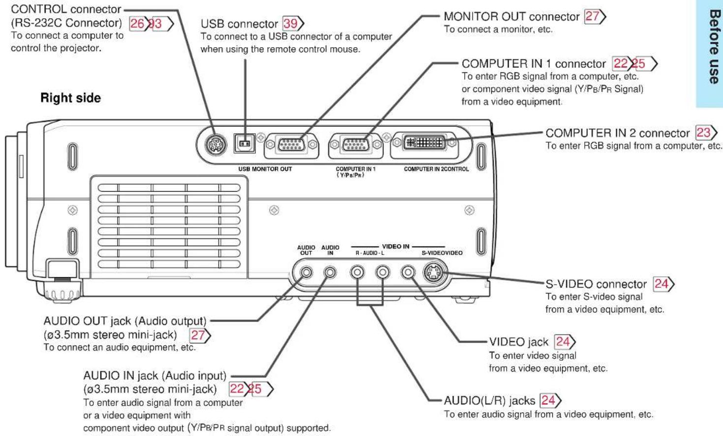
Names of each part on the main unit

11
CAUTION
Openings in the cabinet are provided for ventilation and to ensure reliable operation of the product and to protect it from overheating, and these openings must not be blocked or covered.
The explanation here is only for the model not with the document imaging camera. For the model with the document imaging camera, refer to 74.
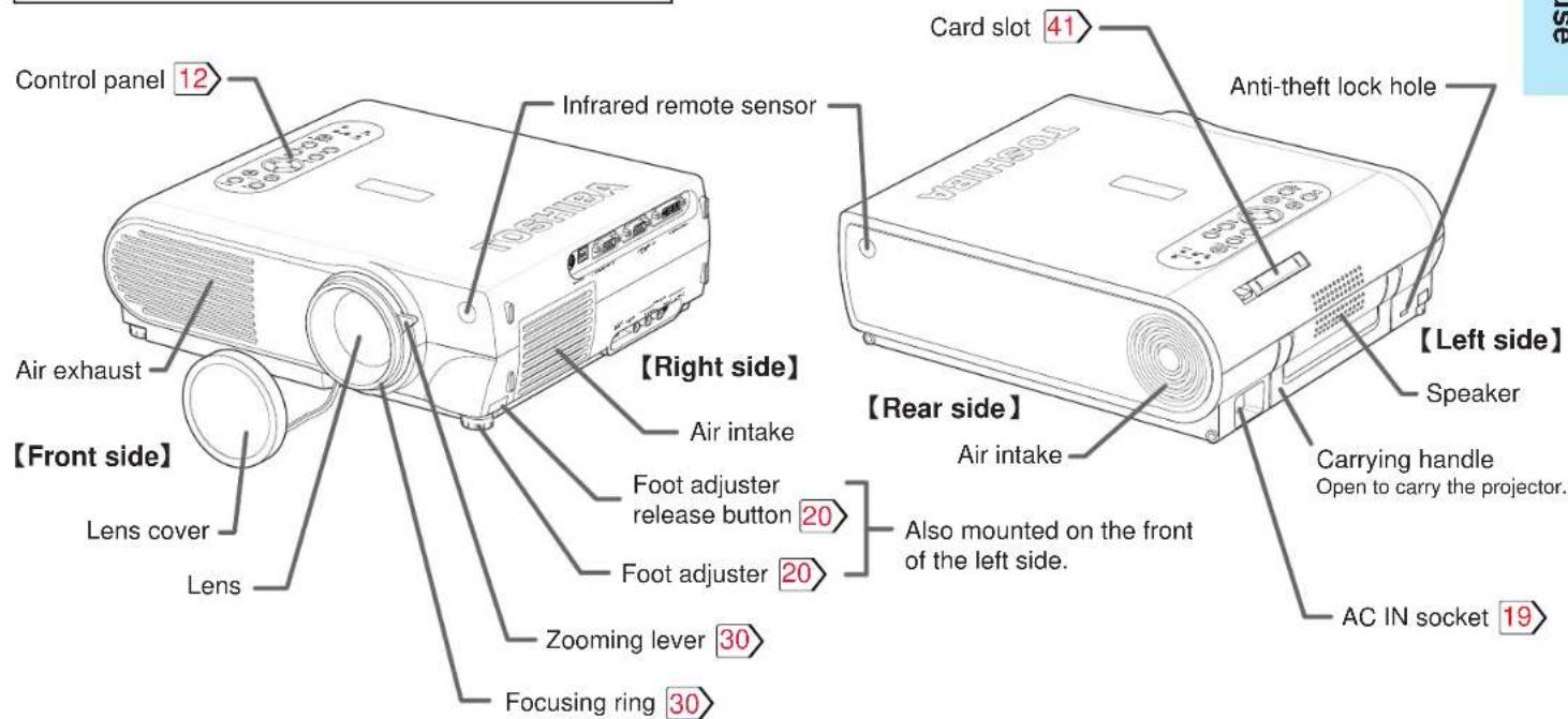
Note
The air exhaust discharges high temperature air. Do not put something around the air exhaust, otherwise it may be deformed by the high temperature air.
Continued

Names of each part on the main unit (continued)
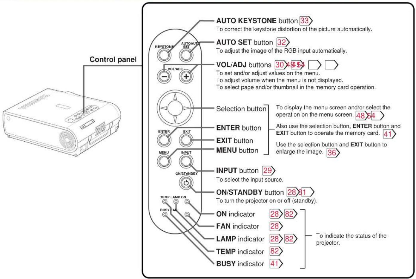
Continued
Names of each part on the main unit (continued)
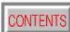
Names of each part on the remote control
Loading batteries
CONTENTS
15
Notes
Using batteries incorrectly can cause them to leak or burst. Strictly observe the following.
- Install the batteries with their + and - ends facing correctly.
- Do not charge, heat, disassemble, or short the batteries or throw them into a fire.
- Do not leave exhausted batteries in the remote control.
- Do not mix different types of batteries or new and old batteries.
- When you will not be using the remote control for a prolonged period, take the batteries out of the remote control.
- When the remote control stops working or only works from very close distance, replace all the batteries with new ones.
- When replacing the batteries, use a more longer life alkaline batteries.
- If a battery leaks, carefully wipe off any residue inside the battery case before loading new batteries.
1
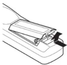
Open the cover.
2
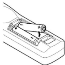
Install the batteries.
Make sure that the + / - polarities match the illustration in the compartment.
3
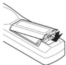
Attach the cover.
Remote control operation

Point the remote control at the infrared remote sensor and press a button.
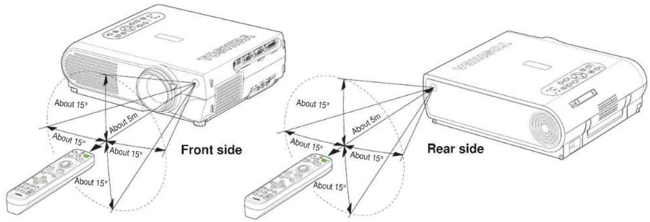
Notes
- The remote control may not operate when there is sunlight or other strong light such as a fluorescent lamp shining on the remote sensor.
- Operate the remote control from a position where the remote sensor is visible.
- Do not drop the remote control or otherwise jolt it.
- Keep the remote control out of locations with excessively high temperature or humidity.
- Do not get water on the remote control or place wet objects on it.
- Do not disassemble the remote control.
- Under unusual circumstances the remote control may not operate well due to the location being used or the surroundings. At such times, change the direction of the remote control to the projector and retry the operation.
Floor-mounted projector placement

17
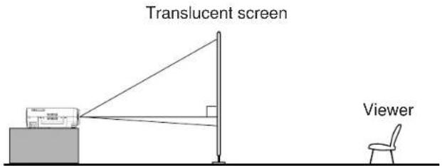
There are two ways to place the floor-mounted projector. Perform the "Projection mode" setting on the menu screen for the projection method. 67
For the ceiling-mounted projector placement, refer to the page 21.
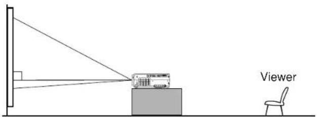
Floor-mounted front projection
Viewing a picture projected on the front of the screen from a floor installation.
Floor-mounted rear projection
Viewing a picture projected through the back of the screen from a floor installation.
Floor-mounted projector placement (continued)

1 Place the projector on a steady, level surface such as a table.
To obtain proper screen projected, place the projector so that the projecting light hits the screen squarely.
Top view
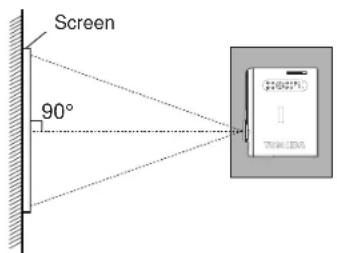
Point the lens straight at the center of the screen as above.
Side view
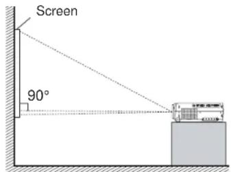
Place the projector horizontally so that the projecting light hits the screen squarely.
Determine the screen size projected on the screen.
The projection size depends on the distance between the lens and the screen.
Adjust the projection size by changing the distances as shown below.
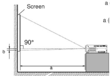
a (.) = Projection size - 0 . 9 3 4 5/2 7 . 3 4 3
a (.) = Projection size - 0 . 7 3 0 1/2 1 . 3 6 2
b = Projection size (cm) × 0. 0 6
a: Distance between the lens and the screen (m)
b: Distance between the lens height and the bottom of projection area (cm)
| Projection size (inches) | a (m) | b (cm) | |
| Minimum (At maximum zoom) | Maximum (At minimum zoom) | ||
| 25 | - | 1.14 | 3.8 |
| 40 | 1.43 | 1.84 | 6.1 |
| 60 | 2.16 | 2.77 | 9.1 |
| 80 | 2.89 | 3.71 | 12.2 |
| 100 | 3.62 | 4.65 | 15.2 |
| 150 | 5.45 | 6.99 | 22.9 |
| 200 | 7.28 | 9.33 | 30.5 |
| 250 | 9.11 | - | 38.1 |
• The values are approximations.
Floor-mounted projector placement (continued)
3
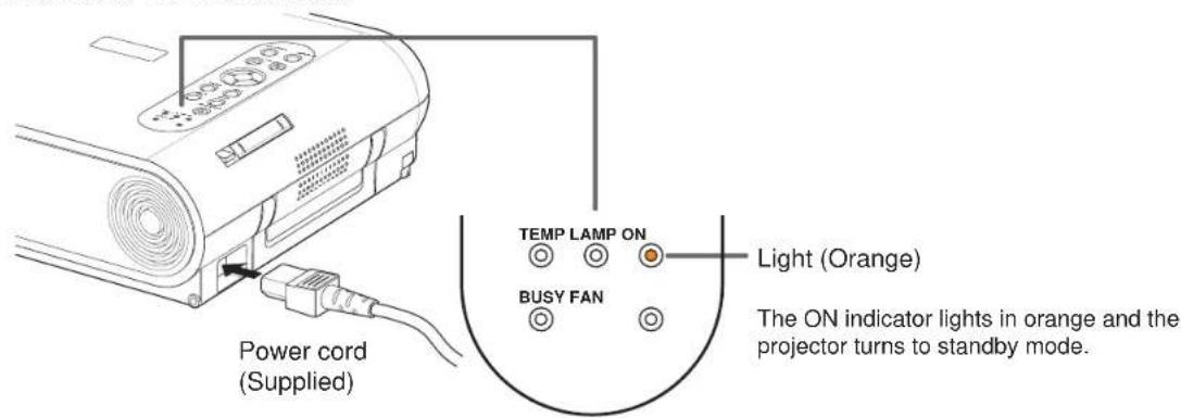
Connect the power cord.
- Insert one end in the AC IN socket on the projector.
- Insert the other end in a wall outlet.
4
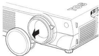
Take off the lens cover.
Notes
- When the projector is moved from a cold location to a warm location, or when the ambient temperature in the projection room has risen suddenly, moisture may condense on the lens or the internal optical section to blur the projected pictures. In such a case, leave the projector for an adequate time (1 to 2 hours, depending on the room's condition) before using it, so it adjusts to the ambient temperature.
- If the screen is exposed to direct sunlight or other strong light, the projected picture becomes too faint to see. Shut out the light with curtains or other means.
- If the screen and the projector are not installed properly, the projected picture may be distorted.
Projector placement angle adjustment

The tilt of the projector can be adjusted using the foot adjuster.
1
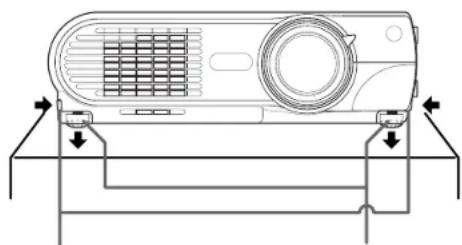
Foot adjuster release button
Foot adjuster
Lift the front of the projector until a tilt angle desired is obtained and hold down the foot adjuster release button.
The foot adjuster will stretch.
Release the button to lock in position.
2
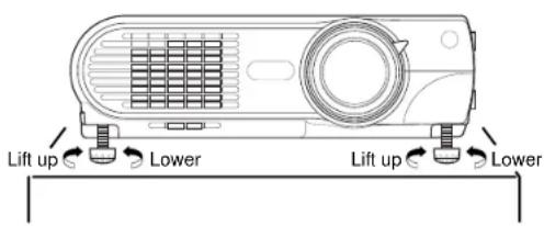
Turn the foot adjuster to make fine adjustment of the height.
Turn clockwise to lift up.
Turn counterclockwise to lower.
Notes
- To put the foot adjuster back, hold down the foot adjuster release button and lower the front slowly.
- Be sure to hold the projector when putting the foot adjuster back so as not to let the front fall on your fingers.
- Do not tilt the projector at an angle exceeding the range adjustable by the foot adjusters, since the duration life of the lamp may be shortened.
Ceiling-mounted projector placement
CAUTION
When a ceiling mount is required, please consult with the dealer.
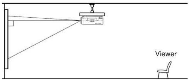
Ceiling-mounted front projection
Viewing a picture projected on the front of the screen from a ceiling installation.
Ceiling-mounted rear projection
Viewing a picture projected through the back of the screen from a ceiling installation.
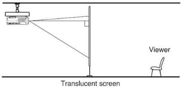
Perform the "Projection mode" setting on the menu screen for the projection method.67
Notes
- For models with a document imaging camera, the ceiling-mounting is not recommended, since the camera arm may hang down if the projector is suspended from the ceiling.
- The relation between the projection size and the distance to the screen is the same as that of the floor-mounted projection mode 18.
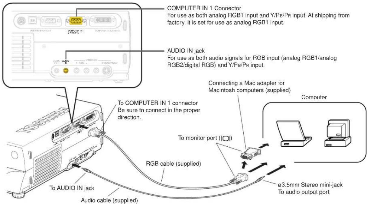
Connecting a computer

You can project the picture from the computer.
Check that the power for the projector and computer is off before connecting the cables.
Notes
- The projector cannot be connected to a computer without an analog RGB connector. For details, refer to the computer manual.
- When connecting to a Macintosh computer, use the supplied Mac adapter (Multiple Scan 21 compatible). For some models the adapter is not required.
- You may not be able to connect some computers to the projector. For details, consult the dealer.
- Some computers may have output modes which are not compatible with this projector. Check the compatibility of the connectors, signal levels, timing, resolutions, etc.
Connecting a computer with DVI output connector
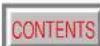
You can project the picture by entering the digital RGB signals from a computer with DVI output connector. Check that the power for the projector and computer is off before connecting the cables.
Notes
- The COMPUTER IN 2 connector can be used to input either digital RGB or analog RGB signals, depending on the connection cable used. The projector's DVI connector is of the DVI analog & digital type. Check the type of output connector on the computer, then purchase the appropriate type of connection cable. (To input analog RGB signals from a computer without a DVI connector, use a DVI cable on which the computer side connector is a mini D-sub 15-pin connector.)
- You may not be able to connect some computers to the projector. For details, consult the dealer.
- Some computers may have output modes which are not compatible with this projector. Check the compatibility of the connectors, signal timing, resolutions, etc.
Connecting video equipment
You can project the picture from video equipment by using VIDEO IN connectors. Check that the power for the projector and video equipment is off before connecting the cables.
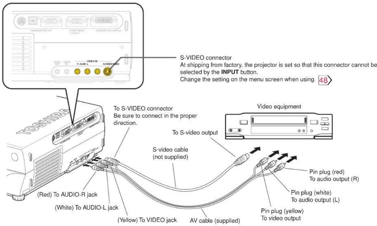

The S-VIDEO connector and VIDEO jack can be used independently, but the audio input jacks are used as both the S-VIDEO and VIDEO input.
Connecting video equipment (continued)
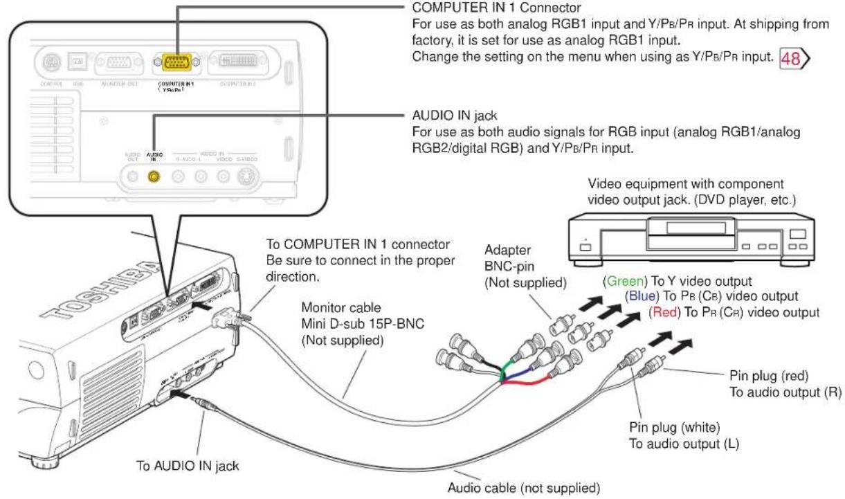
You can project the picture from video equipment with component video output jack. Check that the power for the projector and video equipment is off before connecting the cables.
Note
Some component video signal sources include the Y/CB/CR signals of a DVD player and the Y/PB/PR signals of high definition devices, etc.
Projector operation control by a computer
You can control the projector by a computer connected with the control cable supplied. 93 Check that the power for the projector and computer is off before connecting the cables.
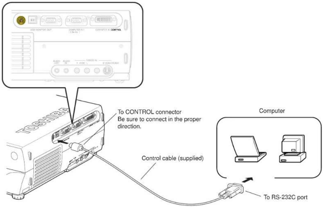

Do not connect a cable other than the exclusive one supplied.
How to use the output connector
You can output video and audio signals to a computer monitor, a stereo system, etc. Check that the power for the projector and the equipments is off before connecting the cables.
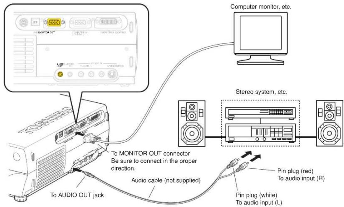
Notes
• The audio signals of the input source selected by the input select operation are output from the AUDIO OUT jack. The signal level (volume) is fixed.
- The analog RGB signals of the COMPUTER IN 1 or COMPUTER IN 2 connector selected by the input select operation are output from the MONITOR OUT connector. If neither of these input sources is selected, the analog RGB signal of the COMPUTER IN 1 connector is output. (Digital RGB signals are not output.)
- Signals are output from the MONITOR OUT connector even when in the standby mode.
- Do not turn the projector on or off with the stereo system, etc., turned on. This may damage the stereo's speakers.
Projection on the screen
CONTENTS
28
CAUTION – Do not look into the projection lens while operating the projector.
Remote control
Control panel (Main unit side)
Preparation
1 Install and connect the projector properly.
2 Take off the lens cover.
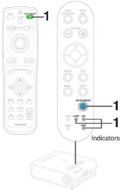
1


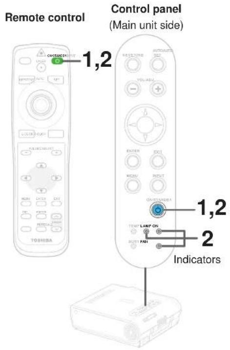
Press ON/STANDBY.
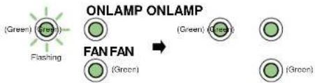
The projector turns on and the ON, LAMP and FAN indicators light in green.
(The LAMP indicator blinks while the lamp is warming up.)
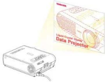
The lamp lights and the start up display appears.
2
Turn on the connected equipment and put it in playback mode.

Select "Cancel" when the dialog box of Add New Hardware Wizard screen appears on the computer.
Continued
Projection on the screen (continued)
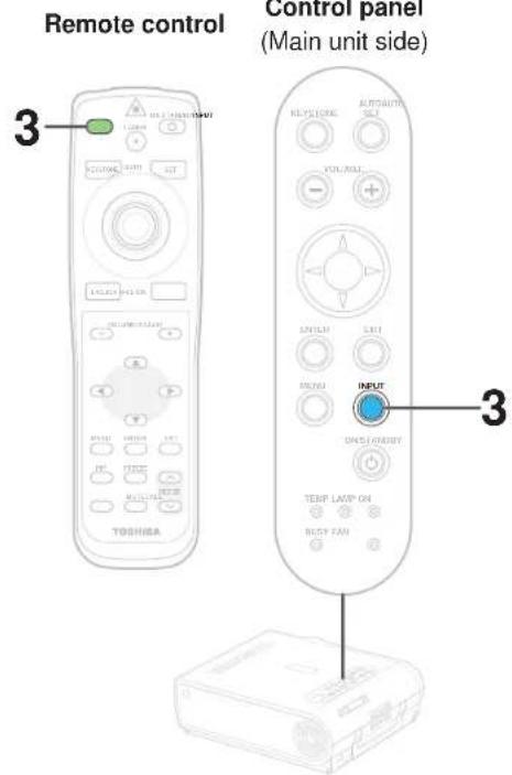
3
INPUT


Select the input source.
Press the INPUT button repeatedly to select it. The icon of the input source selected appears.
(You can select "Camera" when using the model with a document imaging camera.)
COMPUTER-1 COMPUTER-2


Video

S-video

Memory card

Camera

Note
The types of input sources selected when the INPUT button is pressed repeatedly can be set from the menu screen. 48
(At shipping from factory, the projector is set so that the RGB signal source input to the COMPUTER IN 1 connector and the video signal source input to the VIDEO jack can be selected.)

(Signal sent from the computer)
- If you project an image from a computer with an LCD screen while monitoring the image on the computer, the image may not be projected properly, depending on the computer model. In this case, turn off the computer display. For details on controlling the computer display, etc., refer to the computer's manual and description on the software for the computer used.
- The projector projects an image by XGA signal (1024 x 768) in full screen.
- The projector projects an image by VGA or SVGA signal in full screen size, the image quality may be slightly degraded. But, when you set the "Screen size" in the menu screen 54 to "Thru", the display size will be reduced without the image quality be degraded.
- The projector has simplified display compatibility with the signals whose picture dots are more than that of XGA signal. (However, letters and lines can be unequal or a part can be missing. Some signals may not be projected at all.)
- It is recommended to set an external monitor connected to the computer to XGA mode (1024 x 768).
- The projector can be also applied to DDC2B (Display Data Channel 2B). If your computer is applied to the DDC, start up your computer after turning on the projector.
Continued


Projection on the screen (continued)
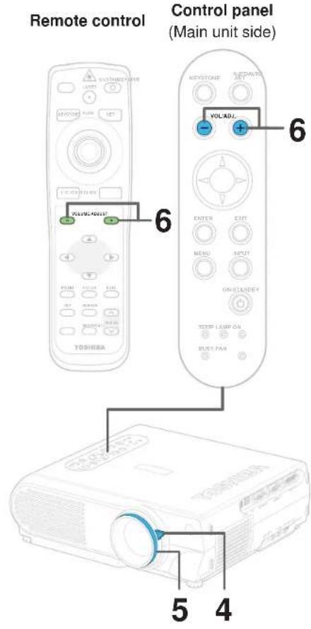
4
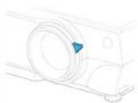
Adjust the picture size by turning the zooming lever.
Turn to the right to enlarge the picture.
Turn to the left to reduce the picture.
5
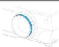
Focus on the picture by turning the focusing ring.
A still picture is recommended for focusing.
6
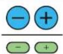
Press VOL/ADJ (+/-) to adjust volume.
Press the (+) button to increase volume.
Press the (-) button to decrease volume.
The volume adjusting bar and the icon appear.

Notes
- When changing the projecting angle, adjust the foot adjuster. 20
- When the screen image is distorted in keystone, press the AUTO KEYSTONE button. 33
- The projector may stop operating if the surrounding temperature is too high or if the air filter is clogged with dust. 82
- Due to the lamp characteristic, flickers may occasionally occur in a picture. This is not malfunction of the unit.
- The projector's liquid crystal panel is made using extremely advanced technology, but there may be black spots (pixels that do not light) or bright spots (pixels that are constantly lit) on the panel. Please note that these are not malfunctions.
- When trying to press the button whose operation is not available, the icon 📋 appears.
- When supplying the signal not compatible to the projector, the icon 📋 appears.
- When signals are not input from the input source, the icon 📄 appears.
Turning the power off
1

Press ON/STANDBY after using the projector.
An instruction message appears.

2

Press ON/STANDBY again.
Cooling starts. Once cooling is completed, the LAMP and FAN indicators turn off and the standby mode is set. (The ON indicator turns in orange.)

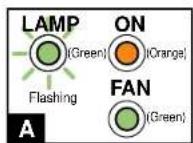
→
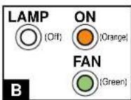
→
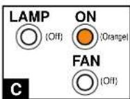
A
To protect the light source lamp, the LAMP indicator blinks as long as a minimum of cooling is necessary. The power cannot be turned back on during this time. Unplugging the power cord at this time will shorten the lamp's duration life.
B
The cooling fan continues to run for a while to expel the heat remaining inside. If you are in a hurry, however, you may unplug the power cord at this time.
C
The standby mode is set.
Notes
- The projector consumes about 20W of power in the standby mode. We recommend you to unplug the power cord when not using the projector for long periods of time.
- Be sure that the LAMP indicator has turned off before unplugging the power cord. Cutting the power by unplugging the power cord while the projector is operating or the light source lamp is being cooled will shorten the lamp's duration life.
Adjusting the picture automatically
Remote control
Control panel
(Main unit side)
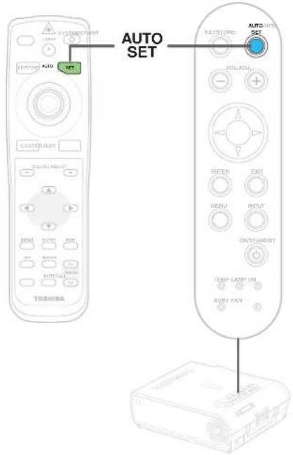
You can adjust the optimum horizontal position, vertical position, sampling phase and sampling frequency for projecting RGB signals at the touch of a button.
1
Input full screen video signals from the input source (computer) and project the image.
Adjustments may not be performed properly for images that are not displayed on the entire screen or extremely dark images.
2
AUTO
SET


Press AUTO SET.
The horizontal position, vertical position, sampling phase and sampling frequency are adjusted automatically.
The icon

appears during signal processing.
Notes
- Automatic adjustment may not be performed properly for signals other than the RGB signals with which the projector is compatible 91.
- The horizontal position, vertical position, sampling phase and sampling frequency can also be adjusted from the menu screen 54.
* Sampling frequency
Analog RGB signals input from the computer are converted into digital signals inside the projector. The sampling frequency is the number of times per second the analog signals are converted into digital signals. In order to capture (sample) each individual dot of the computer's signals, the sampling frequency must be adjusted to match the computer's dot clock frequency. If this adjustment is off, details of the image may be blurred, a striped pattern may appear when images with many vertical lines are displayed, or the image's width may change. For RGB signals with which the projector is compatible, the sampling frequency is adjusted automatically even without pressing the AUTO SET button.
* Sampling phase
The sampling phase is the timing at which the computer's analog RGB signals are sampled. If the sampling phase is off, the individual dots cannot be sampled at the proper timing, resulting in blurred or flickering images.
Correcting the keystone distortion
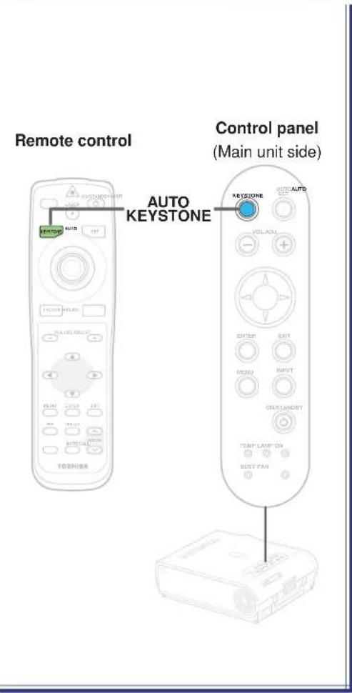
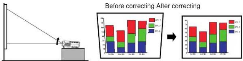
A picture may be expanded on the upper side if projected upward from the projector lifted up by the foot adjuster. The projector can correct this keystone distortion automatically.
Notes
- Due to digital correction processing, some of the information may dropped or the picture quality may be degraded depending on the keystone correction setting or the contents of the signal source.
- Keystone distortion is not corrected properly when the screen is not installed vertically. In this case, adjust from the menu screen.
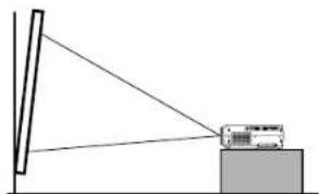
Even if the projector is set horizontal, keystone distortion may occur if the screen is at an angle. In this case automatic correction is impossible.
Cutting off the picture and sound temporarily
Remote control
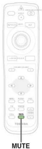
The image and sound of this projector can be turned off if you wish to temporarily project the image of another projector or a OHP, etc., on the screen.

Press MUTE.
The sound and picture are cut off temporarily.
To cancel the mute mode, press MUTE again. The image and sound will be output.
The icon

appears in the mute mode.
Note
The mute mode is cancelled if another operation is performed during the mute mode.
Freezing the picture
Remote control
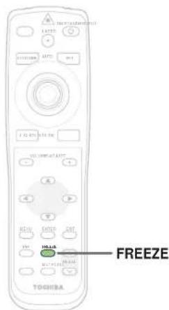
You can freeze the image being projected.
Use this function to stop images from a video recorder to make presentations.

Press FREEZE.
The picture freezes.
To release the picture, press FREEZE again.
The icon 📋 appears in the freeze mode.
Notes
- The freeze mode is cancelled if any other operation is performed during the freeze mode.
- You can not use the FREEZE button when the memory card input is selected.
- The freeze mode cannot be set when there is no input (when no signals are being supplied from a signal source).
- The input source's image continues to play even when the projector is set to the freeze mode.
Enlarging the picture size
Remote control
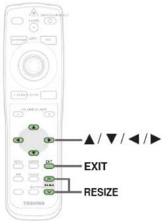
The icon 📄 appears in the resize mode.
You can enlarge (resize) the picture size projected.
![RESIZE Press RESIZE (▲) The enlargement ratio increases each time the RESIZE (▲ button is pressed. The enlargement ratio can be increased continuously by keeping the button pressed in. ABCDEFGHIJKL MNOPQRSTUVW XYZ0123456789! #%&'()[]?<>@' =++ ABCDEFGHIJKL MNOPQRSTUVW YZ0123456789 $%&'()[]?<>@' =++ O…](/content/2026/05/759746/images/9d721c578c597f0051eb6bb6a789912c576e8ba7848d02bf78f8c2649cb1cef5.jpg)
Notes
- Enlarged images can be frozen by pressing the FREEZE button. When frozen, images cannot be enlarged or reduced.
- The resize mode is cancelled if any operation other than setting the freeze mode is performed.
- This projector uses electrical digital resizing, so the picture quality degrades when images are enlarged.
- In rare cases, the picture may be disturbed while the magnification section is being moved.
- With some signals, the image cannot be enlarged.
- This function does not work in no input status (no signal is supplied from the signal source).
Displaying PIP Sub-pictures
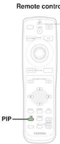
Video or S-video images can be displayed as small images on the computer's image. (Referred to as "sub-pictures" in this manual.)

Press PIP.
A sub-picture is displayed
Press the PIP button again to turn off the sub-picture.
Notes
- The PIP function cannot be used when a source other than an RGB input source is selected.
- The PIP function cannot be used with no signals supplied from an RGB signal source.
- The sub-picture turns off if any other operation is performed.
- The signal source, size, display position and audio input source to display sub-pictures can be changed from the menu screen. 73
Displaying Information

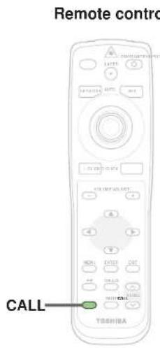
Information on the input signal source, etc., can be displayed.

Press CALL.
The information described below is displayed.
The information display turns off when the CALL button is pressed again.

Status display
Input – current input source
H-resolution – the horizontal resolution of the input signal (at RGB input)
V-resolution – the vertical resolution of the input signal (at RGB input)
H-frequency – the horizontal frequency of the input signal (at RGB input)
V-frequency – the vertical frequency of the input signal (at RGB input)
Video mode – the color mode of the video signal (at video, S-video input)
Signal format— the formatting of the component signal (at Y/PB/PR input)
Card type – the type of the memory card (at memory card input)
Lamp time – the elapsed using time of the lamp
Version – the version of the firmware
Shutter – the shutter speed of the document imaging camera (at document imaging camera input)
Notes
- The information displayed is not refreshed even if it changes. To refresh the information, turn off the information display, then turn it back on.
- The information display turns off if any other operation is performed.
- The "Lamp time" shows an approximate time for lamp replacement. (It should not be used as a lamp warranty time counter.) If the time indicated here nears 1000, contact your store of purchase about obtaining a replacement lamp (TLPLX10, sold separately). The fractions of the actual usage time are discarded from the time indicated here each time the projector is used, so the indicated time is actually somewhat shorter than the actual usage time.
- The "Lamp time" can be reset when the lamp is replaced.
- The "Version" is the version of the control program used in the projector and is used for servicing, etc.
Operating a computer by the remote control

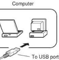
You can control a computer by the remote control when the projector and computer are connected with the supplied USB cable. In this manual, this function is explained as "mouse remote control".
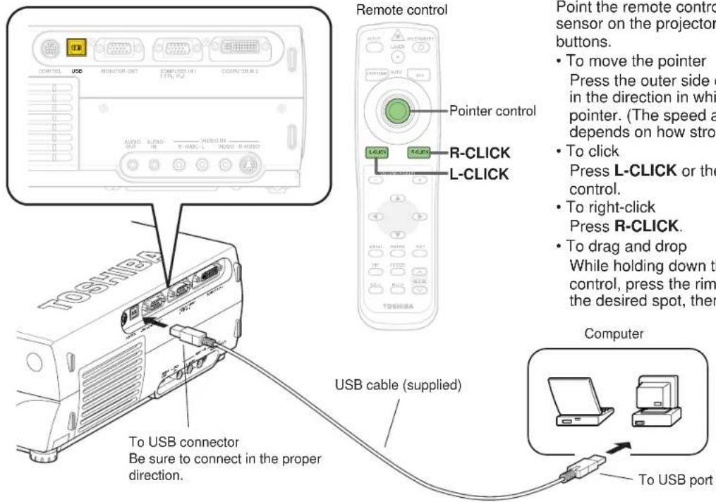
Point the remote control at the remote control sensor on the projector when operating with its buttons.
- To move the pointer
Press the outer side of the pointer control button in the direction in which you want to move the pointer. (The speed at which the pointer moves depends on how strongly the button is pressed.)
• To click Press L-CLICK or the center of the pointer control.
• To right-click Press R-CLICK. - To drag and drop While holding down the center of the pointer control, press the rim side to move the pointer to the desired spot, then release the center part.
Notes
- This function is available with Windows98 and Mac OS9 computers equipped with a USB port as standard.
- When connecting the computer's USB port for the first time, a message asking you to insert the Windows98 CD-ROM may appear on the computer's monitor screen, depending on whether or not the device driver is installed. If so, do as the message says.
- When using a USB cable other than the supplied one, be sure to use a shielded type.
Projecting images stored in a memory card

This projector can read the image data of JPEG format stored in a memory card to project the images on the screen.
For example, you can perform the presentation without a computer by converting the presentation data prepared on the computer into JPEG format and then saving in the memory card. (It cannot reproduce the motion in the same manner of the Microsoft PowerPoint animated effect.)
Read this page carefully before using this function.
About memory cards
- The card slot on the projector conforms with PC Card Standard TYPE II. Use a memory card and converter adapter (PC card adapter) compatible to this type of card slot.
-
The following ATA-compatible recording media (on the market) is available. In this manual all such cards are explained in general as "memory card".
-
Flash ATA card
- SmartMedia™ card (used with a SmartMedia™ PC card adapter)
- CompactFlash card (used with a CompactFlash PC card adapter)
- Memory Stick (used with a Memory Stick PC card adapter)
- Multimedia card (used with a Multimedia PC card adapter)
- SD Memory card (used with an SD Memory card PC card adapter)
• TOSHIBA mobile HDD MEHDD20A
Note that inserting other memory cards, adapters or PC cards with different functions into the projector may damage the card or cause malfunction.
- Memory cards confirmed to operate properly on the projector Toshiba does not guarantee the whole operation.
- Flash ATA card: I-O DATA PCFCA-96M (96MB), PCFCA-128M (128MB)
- SmartMedia card: TOSHIBA PDR-SM16 (16MB), PDR-SM32 (32MB), PDR-
SM64 (64MB)
Adapter: FUJIFILM PC-AD3B, OLYMPUS MA-2
- CompactFlash card: SanDisk SDCFB-64-505 (64MB), SDCFB-128-505 (128MB)
Adapter: SanDisk SDCF-31
• Memory Stick: SONY MSA-32A (32MB)
Adapter: SONY MSAC-PC2N
• Multimedia card: I-O DATA PCMMC-32MS (32MB)
Adapter: I-O DATA PCMMC-ADP
• SD Memory card: Panasonic RP-SD032 (32MB)
Adapter: Panasonic BN-SDAAP3
* The Toshiba IPC5019A, BUFFLO RFD-A2 SmartMedia PC card interface adapter cannot be used.
- For security, we recommend you to back up the data stored in the memory cards before use. (Note that Toshiba will take no responsibility for damages, loss of profits, etc., due to lost data or other problems causing from the use of the projector.)
About JPEG files
1) Folder names must have no more than 11 characters, file names no more than 8 characters.
2) Only compatible with files with the following extensions: .jpg, .JPG, .jpeg, .JPEG
3) The total number of Sub-folders and files in a folder should be within 512.
4) Depending on the JPEG compression format, it may take time to display images.
5) Depending on the JPEG compression format, some images may not be used on the projector.
6) The maximum available file size is 1 MB.
7) The maximum available image size is 1280 x 1024 dots.
* If you record the JPEG file into the memory card after converting the JPEG files with the exclusive utility software (contained in the supplied CD-ROM), the processing time of the 4) above can be shortened. Moreover, the restrictions above-mentioned in the 5) to 7) can be eased.
Projecting images stored in a memory card (continued)
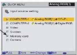
1 When using the memory card function for the first time, set the "Input source setting" on the menu screen.
With the factory default setting, it is impossible to select the memory card input by the INPUT button. Change the setting following the instructions of "QUICK MENU Adjustments and Settings" 48 to make the memory card input selectable.
Check "Memory card".
2
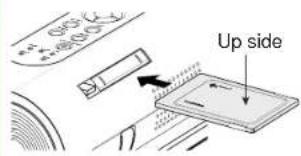
Insert the memory card into the card slot.
Insert the card securely, pressing it as far as it can go.
Be careful to insert the card in the proper direction. The slot is designed so that it is difficult to insert cards in the wrong direction. Inserting the card forcibly may deform the internal terminals or cause other problems.
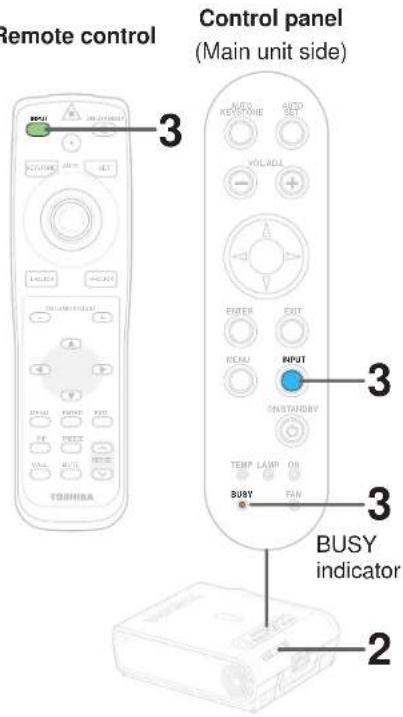
3
INPUT

INPUT

BUSY

(Light in orange)
Press INPUT repeatedly to select the memory card input.
The "Memory card" input display appears on the screen.
- Start to read the data on the memory card and display the image data sequentially as thumbnails.
- The BUSY indicator lights in orange while the memory card is being accessed. (Do not eject the memory card while the BUSY indicator is lit.)
Continued

Projecting images stored in a memory card (continued)
Remote control
The icon 📋 appears during image data processing.
3 (Continued)
Description of screen
The illustration below is an example for explanation purpose only. The actual display, the number of directory, etc., differs depending on the data stored in the memory card.
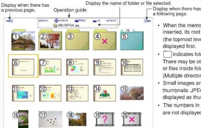
①, ②: Folders containing JPEG files
③: Folders which may contain JPEG files in lower directory
④: Folders not containing JPEG files
⑤: Folders with camera images stored. (For the models with document imaging camera)
⑥ to ⑱: JPEG files stored in the currently displayed directory
⑲: JPEG files that cannot be displayed as thumbnails
⑳: Files not compatible
⑥: The orange frame indicates the currently selected JPEG file
4

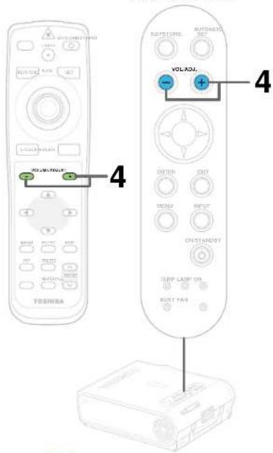
Use VOL/ADJ (+/-) to change pages. (Page changing)
When an icon (◀ or ▶) is displayed to indicate that there is a previous or following page, use the VOL/ADJ (+/-) buttons to change pages and search for the desired thumbnails or folders.
Continued
Projecting images stored in a memory card (continued)
CONTENTS
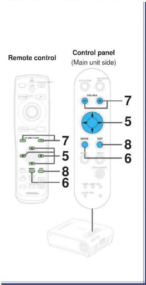
5
Use the selection buttons (▲/▼/◄) to select the thumbnail you wish to display as a slide. (Thumbnail selection)
• The selected thumbnail is surrounded by an orange frame.
- If the desired file (thumbnail) is in a different folder, select that folder.
6
Press ENTER. (Slide display)
- When a thumbnail is selected, that image is displayed as a slide (a large picture).
- When a folder is selected, the contents of that folder are displayed as thumbnails in the same way as in step 3 above. In this case, return to step 5 or 4.
When a folder is selected, repeat steps 5 and 6 until the desired thumbnail is displayed. The maximum number of folder directory levels that can be searched through at this time is within 5 levels from the root directory (up to 5 levels of folders).
7
Press VOL/ADJ (+/-). (Slide transition)
- Press the (+) button to display the next slide.
- Press the (-) button to display the previous slide.
You can only change the JPEG files stored in the same directory level (including the previous and following pages) by the VOL/ADJ (+/-) buttons.
8
Press EXIT.
The display returns to as it was in step 3. If you have searched to the bottommost level in step 5, pressing the EXIT button repeatedly moves the display sequentially back up to higher levels until the contents of the root directory are displayed.
Continued
Projecting images stored in a memory card (continued)
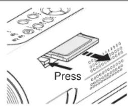
To eject the memory card
To eject a memory card, first check that the BUSY indicator is off, then press the card slot's eject button. The memory card pops out part way, then pull it out by hand.
Notes
- In the memory card input mode, you can perform the operations described below using the menu screen settings.
• Automatic input selection function
When "Input select mode" 54 is set to "Auto.", the mode automatically switches to the memory card input mode when a memory card is inserted.
• Auto slide show 1
When "Auto. demo" 48 is set to "On" and a memory card is loaded, a slide show of the JPEG files in the root directory starts automatically when the memory card input mode is selected.
- Auto slide show 2
When "Slide show" 54 is set to "Auto.", a slide show starts automatically at the place where the leading thumbnail appointed in the step 6.
- Auto slide show 3
When "Input select mode" is set to "Auto.", "Auto. demo" is set to "On" and memory card is loaded, a slide show of the JPEG files in the root directory starts automatically when the power is turned on. When "Power on" [67] is set to "Auto.", the slide show starts when the power cord is plugged into an outlet.
Press the EXIT button to stop the automatic slide show.
* In this manual, "Slide show" means the operation by which slides (large images) are displayed in sequence.
- With the factory default settings, the followings are set for manual operation.
Input selection mode: Manual
Auto. demo: Off
Slide show: Manual
Power on: Manual
- You can select the interval time of automatic slide show transition among four types on the menu screen. 48 Depending on the compression format of the JPEG files, however, it may take more than the set time to transit images.
- Depending on the compression format of the JPEG files and the file sizes, it may take a time for page changing or slide transition.
- The sort order (thumbnail displaying order = slide show order) of JPEG files is in character number order. When the number of characters is the same, the sort order is arranged by the numerical characters used in each file name at first and then the alphabetical characters.
Adjustments and settings on the menu screen

- The menu screens for making various adjustments and settings include a QUICK MENU for frequently used adjustments and settings and a FULL MENU for all the adjustments and settings. The FULL MENU is divided into six sections by function: "Picture", "Audio", "Keystone", "Display", "Default setting" and "Factory reset mode".
- The items in the "Picture" and "Audio" sections of the QUICK MENU and FULL MENU differ depending on the input source.
- Some of the adjustments and settings are stored separately for different input sources, others are applied to all input sources when they are set for one. For details, refer to the pages on which the individual adjustment and setting instructions are located.
| Analog RGB 1 Analog RGB 2 |
| Contrast |
| Brightness |
| Phase |
| Picture mode |
| Keystone |
| Lamp power |
| Input source setting |
| Language |
| Digital RGB Mer | |
| Contrast | |
| Brightness | |
| Picture mode | |
| Keystone | |
| Lamp power | |
| Input source setting | |
| Language | |
| cy card/PB/PR |
| Contrast |
| Brightness |
| Color |
| Keystone |
| Lamp power |
| Input source setting |
| Language |
| VideoS-video |
| Contrast |
| Brightness |
| Color |
| Keystone |
| Lamp power |
| Input source setting |
| Language |
| Contrast |
| Brightness |
| Auto. demo |
| Interval |
| Keystone |
| Lamp power |
| Input source setting |
| Language |
| Document imaging camera(With camera model) |
| Contrast |
| Brightness |
| Shutter |
| Keystone |
| Lamp power |
| Input source setting |
| Language |
| Picture Picture |
| Contrast |
| Brightness |
| Phase |
| Frequency |
| Position |
| Picture mode |
| Screen size |
| Level |
| Picture Picture Picture Picture |
| Contrast |
| Brightness |
| Position |
| Picture mode |
| Screen size |
| Level |
| Contrast |
| Brightness |
| Color |
| Tint |
| Sharpness |
| Signal format |
| Screen size |
| Level |
| Contrast |
| Brightness |
| Color |
| Tint |
| Sharpness |
| Video mode |
| Screen size |
| Level |
| Contrast |
| Brightness |
| Input select mode |
| Auto. demo |
| Slide show |
| Interval |
| Screen size |
| Level |
| Contrast |
| Brightness |
| Sharpness |
| Shutter |
| Screen size |
| Level |
| Audio Audio At |
| Speaker output |
| Channel select (Mini) |
| Loudness (Mini) |
| Keystone Keysto |
| Keystone |
| Horizontal reference value reset |
| Audio Audio Audio |
| Speaker output |
| Channel select (Mini) |
| Loudness (Mini) |
| Keystone Keystone Key |
| Keystone |
| Horizontal reference value reset |
| Speaker output |
| Channel select (Mini) |
| Loudness (Mini) |
| one Keystone |
| Keystone |
| Horizontal reference value reset |
| Speaker output |
| Channel select (RCA) |
| Loudness (RCA) |
| Keystone |
| Horizontal reference value reset |
| There is no audio signal in this input. |
| KeystoneHorizontal reference value reset |
| There is no audio signal in this input. |
| KeystoneHorizontal reference value reset |
| Display Display |
| Language |
| No signal background |
| Icon |
| Menu position |
| Menu background translucent |
| Start-up screen |
| Default setting |
| Input source setting |
| Lamp power |
| Projection mode |
| No signal power off |
| Power on |
| splay Display |
| Language |
| No signal background |
| Icon |
| Menu position |
| Menu background translucent |
| Start-up screen |
| Default setting |
| Input source setting |
| Lamp power |
| Projection mode |
| No signal power off |
| Power on |
| Display Display |
| Language |
| No signal background |
| Icon |
| Menu position |
| Menu background translucent |
| Start-up screen |
| Default setting |
| Input source setting |
| Lamp power |
| Projection mode |
| No signal power off |
| Power on |
| Language |
| No signal background |
| Icon |
| Menu position |
| Menu background translucent |
| Start-up screen |
| Default setting |
| Input source setting |
| Lamp power |
| Projection mode |
| No signal power off |
| Power on |
| Language |
| No signal background |
| Icon |
| Menu position |
| Menu background translucent |
| Start-up screen |
| Default setting |
| Input source setting |
| Lamp power |
| Projection mode |
| No signal power off |
| Power on |
| Language |
| No signal background |
| Icon |
| Menu position |
| Menu background translucent |
| Start-up screen |
| Default setting |
| Input source setting |
| Lamp power |
| Projection mode |
| No signal power off |
| Power on |
| Factory reset mode |
| Picture only |
| All |
| Factory reset mode |
| Picture only |
| All |
| Factory reset mode |
| Picture only |
| All |
| Factory reset mode |
| Picture only |
| All |
| Factory reset mode |
| Picture only |
| All |
| Factory reset mode |
| Picture only |
| All |
Adjustments and settings on the menu screen (continued)

QUICK MENU

| Item Meaning | |
| Contrast Adjust the image contrast | |
| Brightness Adjust the image brightness (paying attention to the dark parts) | |
| Color Adjust the image color (except for RGB inputs) | |
| Phase Adjust the image flicker (analog RGB) | |
| Picture mode Set brightness priority or picture quality (color) priority (RGB) | |
| Auto. demo Set the automatic slide show function on and off (memory card) | |
| Interval | Set the interval time to transit the automatic slide show (memory card) |
| Shutter Set the shutter speed (document imaging camera) | |
| Keystone Adjust keystone distortion | |
| Lamp power Set the lamp power (cooling sound selection) | |
| Input source setting Set the input mode selected by the INPUT button | |
| Language Set the display language used for menus and messages | |
FULL MENU
| Picture | 54 |
| Item Meaning | |
| Contrast Adjust the image contrast | |
| Brightness Adjust the image brightness | |
| Color Adjust the image color | |
| Tint Adjust the image tint | |
| Sharpness | Adjust the image sharpness |
| Phase Adjust the image flicker (dot clock timing adjustment) | |
| Frequency | Adjust the vertical stripes with detailed images (dot clock frequency adjustment) |
| Position | Adjust the horizontal and vertical positions of the image |
| Level | Adjust the red, green and blue level (balance) |
| Picture mode Set brightness priority or picture quality (color) priority | |
| Video mode | Set the video or S-video color system |
| Signal format | Set the Y/PB/PR signal DTV format |
| Screen size | Set whether to convert to XGA size or display with the input resolution |
| Input select mode | Set the input selection Auto./Manual at memory card detection |
| Auto. demo Set the automatic slide show On/Off at memory card detection | |
| Slide show | Set slide show advancing Auto./Manual |
| Interval | Set the interval time to transit the automatic slide show |
| Shutter Set the shutter speed according to the power supply frequency | |
Audio

(Adjust the audio output from the speaker on the main unit)
| Item Meaning | |
| Speaker output | Set the speaker output On/Off |
| Channel select (RCA) | Select the channel of AUDIO (L/R) jack in VIDEO IN |
| Loudness (RCA) | Set the loudness of AUDIO (L/R) jack On/Off in VIDEO IN |
| Channel select (Mini) | Select the channel of AUDIO IN jack |
| Loudness (Mini) | Set the loudness of the AUDIO IN jack On/Off |
Keystone

| Item Meaning | |
| Keystone Adjust the Keystone distortion | |
| Horizontal reference value reset | Reset the horizontal reference value for the automatic adjustment |
Display

| Item Meaning | |
| Language Set the display language used for menus and messages | |
| No signal background | Set the background at no signal input |
| Icon | Set the icon display On/Off |
| Menu position | Set the position of the menu screen |
| Menu background translucent | Set the menu background translucent On/Off |
| Start-up screen | Set the start-up screen at power on |
ault setting

| Item Meaning | |
| Input source setting Set the input mode selected by the INPUT button | |
| Projection mode | Set the direction of the screen according to the projection mode |
| No signal power off | Set the automatic power off function On/Off when no signal status continues |
| Power on | Set the power on On/Off when plugging the power cord |
| Lamp power Set the lamp power (cooling sound selection) | |
Factory reset mode

| Item Meaning | |
| Picture only | Return the items of the picture menu to the factory default setting for each input source. |
| All | Return all of the items to the factory default setting for all input sources. |
Note
An exclusive menu is displayed when making PIP function sub-picture settings. 73
Operating the menu screen
CONTENTS
![Start Press the MENU button to display the QUICK MENU. Selected item (orange) Input source name QUICK MENU Analog RGB(1) Contrast +6 Brightness 0 Phase 0 Picture mode Bright true color Keystone 0 Lamp power Hi Low Input source setting [ENTER] [ENTER] Language Adjust the contrast of the image. FULL I…](/content/2026/05/759746/images/9dec411db2006d57bf42a234b91cdcdba91bc75413329725c3e439bcb865f3f3.jpg)
Preparation
1 Project a picture on the screen as explained in the step "Projection on the screen". 28
1


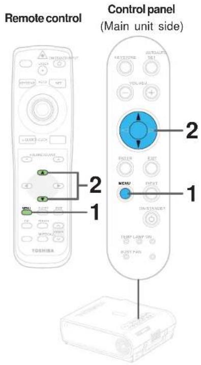
Press MENU.
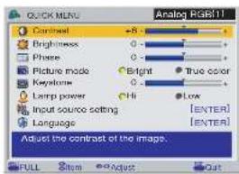
The QUICK MENU appears.
![QUICK MENU Analog RGB11 Contrast +8 - Brightness 0 - Phase 0 - Picture mode Bright True color Keystone 0 - Lamp power 11 Low Input source setting [ENTER] Language [ENTC] Adjust the contrast of the image. FULL Set No Adjust OUT](/content/2026/05/759746/images/e2cf2fba86bcdfbc04331b1ed68f557b6df2cc2a45d68780d7fccfef8c320fe7.jpg)
• To cancel the QUICK MENU screen, press the EXIT button.
- The contents of the menu are different depending on the type of input source currently selected.
QUICK MENU adjustments and settings (continued)
Remote control
Control panel
(Main unit side)
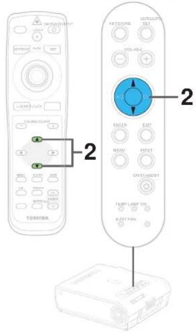
2


Use the selection buttons (▲) No select the adjustment and setting items.
The types of adjustment and setting items are different depending on the type of input source currently selected. (See the table below.)
Adjustments
O: Adjustable X: Not displayed
| Items\Inputs | Analog RGB1 | Analog RGB2 | Digital RGB | Y:PePx | Video | S-video | Memory Card | Document Imaging Camera |
| Contrast | O | O | O | O | O | O | O | O |
| Brightness | O | O | O | O | O | O | O | O |
| Color | X | X | X | O | O | O | X | X |
| Phase | O | O | X | X | X | X | X | X |
| Keystone | O (same for all of the inputs) | |||||||
Settings
O: Adjustable X: Not displayed
| Items\Inputs | Analog RGB1 | Analog RGB2 | Digital RGB | Y/Ps/Pa | Video | S-video | Memory Card | Document Imaging Camera |
| Picture mode | O | O | O | X | X | X | X | X |
| Lamp power | O (same for all of the inputs) | |||||||
| Input source setting | O (same for all of the inputs) | |||||||
| Language | O (same for all of the inputs) | |||||||
| Auto. demo | X | X | X | X | X | X | O | X |
| Interval | X | X | X | X | X | X | O | X |
| Shutter | X | X | X | X | X | X | X | O |
Note
The "Keystone" adjustment and the "Lamp Power", "Input source setting" and "Language" settings are applied to all the input sources. (It is impossible to make different settings for each input source.)
Other items marked "O" can be adjusted or set respectively for the different input sources.
Continued
QUICK MENU adjustments and settings (continued)

When selecting "Contrast", "Brightness", "Color", "Phase", "Keystone", "Picture mode", "Lamp power", "Auto.demo" or "Shutter" in step 2.



Press VOL/ADJ (+/-) to adjust and set.
| Adjustments | ||
| Items Buttons | (-) (+) | |
| Contrast Lower Higher | ||
| Brightness Darker Brighter | ||
| Color Thinner | Deeper | |
| Phase | Adjust flickers | Adjust flickers |
| Keystone | Reduce the lower width | Reduce the upper width |
Settings
Picture mode (Analog RGB input, digital RGB input)
Bright: Set the picture with its brightness priority. True color: Set the picture with its quality (color) priority.
Lamp power
Hi: Set the lamp mode with brightness priority. Low: Restrict the lamp output to reduce the cooling sound.
Auto. demo (Memory card input)
On: When a memory card is detected while the memory card input mode is selected, a slide show using the image data in the root directory starts automatically.
Shutter (Document imaging camera input)
Set to the frequency (50/60 Hz) of the power supply in your area.
Note
The cooling sound changes according to the temperature inside the projector. When the lamp power setting is changed, the brightness changes immediately, but the cooling sound level does not change immediately.
Continued
QUICK MENU adjustments and settings (continued)

Remote control
When selecting "Input source setting" in step 2. (Set the input source that can be selected by the INPUT button.)

ENTER

ENTER


Press ENTER.
The sub-menu screen of input source setting appears.
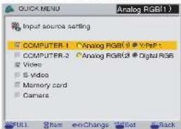
| Menu items | Main unit indication |
| COMPUTER-1 | COMPUTER IN 1 |
| COMPUTER-2 | COMPUTER IN 2 |
| Video | VIDEO |
| S-video | S-VIDEO |
| Memory card | |
| Camera | Document imaging camera(For the model with camera) |
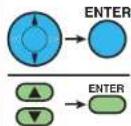
Use the selection buttons (▲) No select the input source to be set, then press ENTER to check it.
- The check turns on and off each time the ENTER button is pressed.
- When a check box is checked, that input source can be selected by the INPUT button.

(When selecting COMPUTER-1 and COMPUTER-2)
Press VOL/ADJ (+/-) to select the type of input source.
The setting whose button is displayed in yellow is the one currently selected.
Press EXIT to return to the QUICK MENU.
EXIT

EXIT

Notes
- It is impossible to exit from the menu if no input source is selected.
- If the check in the check box for the currently selected source is removed, the setting becomes effective the next time the input is changed.
- For the memory card and document imaging camera, there are modes in which these can be selected even if their check box is not checked. 56 77 Continued
Continued
QUICK MENU adjustments and settings (continued)
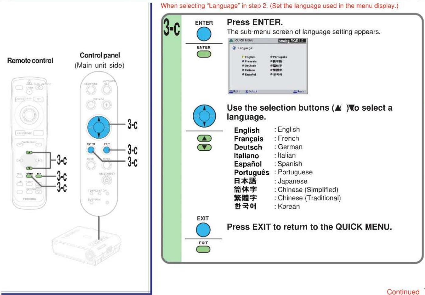
QUICK MENU adjustments and settings (continued)
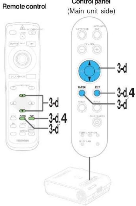
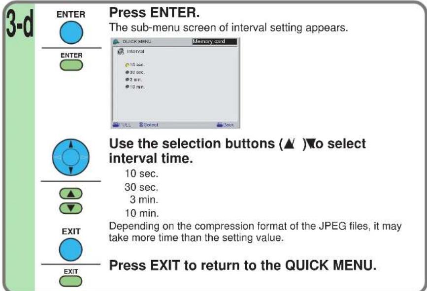
When selecting "Interval" in step 2. (Set the interval time of the automatic slide show.)

Notes
- If the power is turned off by pressing the ON/STANDBY button, the adjustments or settings made are automatically stored in the memory. If the power cord is unplugged or if a power failure occurs while the projector is on, the adjustments or settings are not stored in the memory.
- The adjustments or settings are stored for each of the items marked "O" in the table in step 2.
FULL MENU adjustments and settings – Picture
54
You can adjust contrast, brightness, color level, image position, etc.
Preparation
1 Project a picture on the screen as explained in the step "Projection on the screen". 28
1


Press MENU twice.
When pressed once, the QUICK MENU screen appears. When pressed twice, the "Picture" screen of the FULL MENU appears.

![Analog RGB (1) Picture Contrast +8 Brightness - Please - Frequency - Position - Picture mode (Bright) ●True color Screen size (Full) ●Thru Level [ENTER] [ENTER] QUICK Style Page Adjust Cut](/content/2026/05/759746/images/bd4e9ef1c7d799d77996a7dc00d401bbe6d4a117e6a3d3f7935d2ff0d6ce2492.jpg)
2


Use the selection buttons (▲ / ▼) to select the adjustment and setting items.
The types of adjustment and setting items are different depending on the type of input source currently selected. (See the table below.)
Adjustments
O: Adjustable X: Not displayed
| Items\Inputs | Analog RGB1 | Analog RGB2 | Digital RGB | Y/Ps/Pr | Video | S-video | Memory Card | Document Imaging Camera |
| Contrast | O | O | O | O | O | O | O | O |
| Brightness | O | O | O | O | O | O | O | O |
| Color | X | X | X | O | O | O | X | X |
| Tint | X | X | X | O*1 | O*2 | O*2 | X | X |
| Sharpness | X | X | X | O*1 | O | O | X | O |
| Phase | O | O | X | X | X | X | X | X |
| Frequency | O | O | X | X | X | X | X | X |
| Position | O | O | O | X | X | X | X | X |
| Level | O | O | O | O | O | O | O | O |
*1: Adjustment is impossible at 480i mode.
*2: Adjustment is impossible at PAL/SECAM.
Continued

FULL MENU adjustments and settings – Picture (continued)

2 (Continued)
| Items\Inputs | Analog RGB1 | Analog RGB2 | Digital RGB Y/P | 3/4Pa | Video S-video | Memory Card | Document Imaging Camera | |
| Picture mode | O | O | O | X | X | X | X | X |
| Screen size | O | O | O | O | O | O | O | O |
| Signal format | X | X | X | O | X | X | X | X |
| Video mode | X | X | X | X | O | O | X | X |
| Input select mode | X | X | X | X | X | X | O | X |
| Auto. demo | X | X | X | X | X | X | O | X |
| Slide show | X | X | X | X | X | X | O | X |
| Interval | X | X | X | X | X | X | O | X |
| Shutter | X | X | X | X | X | X | X | O |
When selecting "Contrast", "Brightness", "Color", "Tint", "Sharpness", "Phase", "Frequency", "Picture mode", "Screen size", "Input select mode", "Auto. demo" or "Slide show" in step 2.
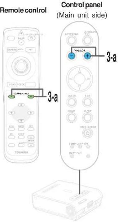
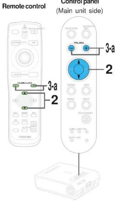
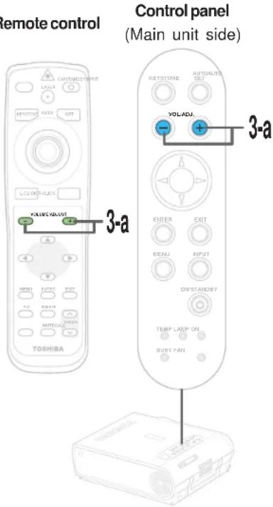
3-a
Press VOL/ADJ (+/-) to adjust and set.
| Adjustments | ||
| Items Buttons | (-) | (+) |
| Contrast | Lower | Higher |
| Brightness | Darker | Brighter |
| Color | Thinner | Deeper |
| Tint | Redder | Greener |
| Sharpness | Softer | Sharper |
| Phase | Adjust flickers | Adjust flickers |
| Frequency | Adjust vertical stripes | Adjust vertical stripes |
Continued

FULL MENU adjustments and settings – Picture (continued)

Remote control
3-a (Continued)
Settings
Picture mode (RGB input)
Bright: Set the picture with its brightness priority. True color: Set the picture with its quality (color) priority.
Screen size
Full: Images are converted to display in 1024 x 768 dots. In the memory card input mode, if the image data's aspect ratio is anything other than 4:3, the image is adjusted so that either the width or the height (the larger of the two) becomes full size. Note that images of 640 x 480 dots or smaller cannot be displayed in full size.
Thru: Images are displayed in the input resolution. Parts larger than 1024 x 768 dots are not displayed. Note that only signal sources whose clock frequency is 140 MHz or less can be displayed at the input resolution.
Wide: To display a wide screen image compressed in a left-right squeeze operation by a DVD player, etc. in an original wide screen size.
Input select mode (Memory card input)
Auto: Regardless of the setting by the "Input source setting" menu, the input source automatically switches to the memory card input mode when a memory card is detected.
Manual: Set the mode according to the setting by the "Input source setting" menu.
Auto. demo (Memory card input)
On: When a memory card is detected while the memory card input mode is selected, a slide show using the image data recorded in the root directory of memory card starts automatically.
Slide show (Memory card input)
You can set when the "Auto. demo" is Off.
Auto: Execute the slide show automatically.
Manual: Execute the slide show manually.
Shutter (Document imaging camera)
Set to the frequency (50/60 Hz) of the power supply in your area.
Continued
FULL MENU adjustments and settings – Picture (continued)

When selecting "Position" or "Level" in step 2.
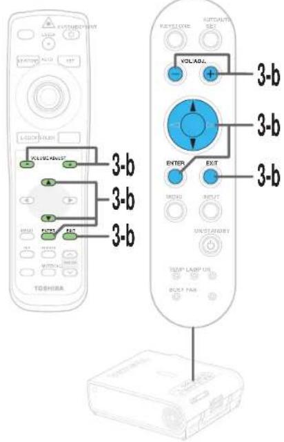
3-b
ENTER


Press ENTER.
The sub-menu of selected items appears.
"Position"
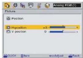
"Level"
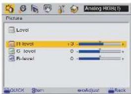



Use the selection buttons (▲ / ▼) to select adjustment items.
Press VOL/ADJ (+/-) to adjust.
| Items\Buttons | (-) | (+) | |
| Position | H-position | Move the picture leftward | Move the picture rightward |
| V-position | Move the picture down | Move the picture upward | |
| Level | R-level | To reduce red | To increase red |
| G-level | To reduce green | To increase green | |
| B-level | To reduce blue | To increase blue | |


Press EXIT to return to the FULL MENU.
FULL MENU adjustments and settings – Picture (continued)
When selecting "Signal format", "Video mode" or "Interval" in step 2.

ENTER


Press ENTER.
The sub-menu of selected items appears.
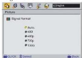
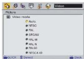
"Signal format" "Video mode"
"Interval"


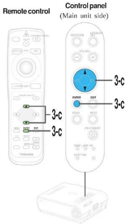
Use the selection buttons (▲ / ▼) to select setting items.
Signal format (Y/PB/PR input)
Auto: Determine the type of the signal input automatically. If not determined properly, select among the signals shown below. 480i, 480p, 720p, 1080i
Video mode (Video input, S-video input)
Auto: Determine the type of the signal input automatically. If not determined properly, select among the signals shown below. NTSC, PAL, SECAM, PAL-M, PAL-N, PAL60, NTSC4.43
Continued

FULL MENU adjustments and settings – Picture (continued)
CONTENTS
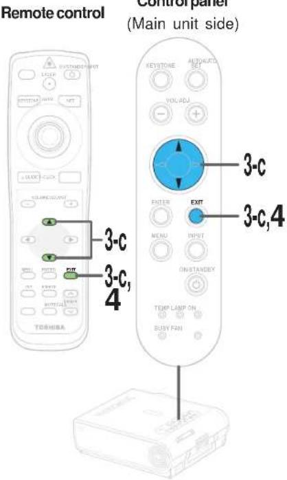
3-c
(Continued)
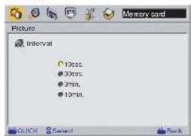
Interval (Memory card input)
Select the display interval (time) for the auto. demo and auto. slide show. (10 sec., 30 sec., 3 min. or 10 min.)
Depending on the compression format of the JPEG files, it may take more time than the setting value.
Press EXIT to return to the FULL MENU.
4
After the adjustments and settings are finished, press EXIT.
The menu screen disappears.
Notes
- If the power is turned off by pressing the ON/STANDBY button, the adjustments or settings made are automatically stored in the memory. If the power cord is unplugged or if a power failure occurs while the projector is on, the adjustments or settings are not stored in the memory.
- The adjustments or settings are stored for each of the items marked "O" in the table in step 2. (It is impossible to store adjustments for each video mode or signal format.)
FULL MENU settings – Audio
You can set the audio signals developed from the speaker. (The speaker output is monaural.)
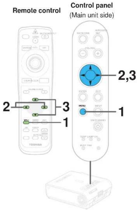
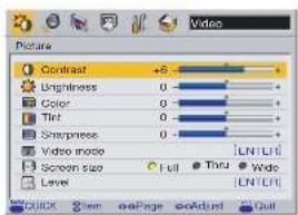
Preparation
1 Project a picture on the screen as explained in the step "Projection on the screen". 28
1


Press MENU twice.
When pressed once, the QUICK MENU screen appears. When pressed twice, the "Picture" screen of the FULL MENU appears.
![QUICK MENU Video Contrast +5 Brightness 0 Color 0 Keystone 0 Lamp power 11 Input source setting [LN (LT)] Language [LN (LT)] Adjusted the contrast of the image. FULL Item + Adjust Out](/content/2026/05/759746/images/200ea8e23c10ce4524bc632d7572c04032124e5aabf768eb916d08ad59a63cc4.jpg)

2


Use the selection button (▶) to display the "Audio" menu.
If you pass by the "Audio" menu, press the selection button (◀) to move back to it.
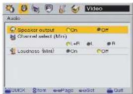
3

Use the selection buttons (▲ / ▼) to select the setting items.
(RCA): Audio input jack (R-AUDIO-L) of VIDEO IN (Mini): AUDIO IN jack
Continued
FULL MENU settings – Audio (continued)
Remote control
Control panel
(Main unit side)
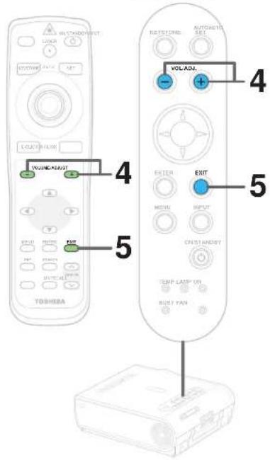
4
Press VOL/ADJ (+/-) to adjust and set.
Speaker output
When set to "Off", no sound is produced from the speakers.
Channel select
L+R: The sound of the left and right channels is mixed and developed from the speakers.
L: To develop only left input audio signal from the speakers.
R: To develop only right input audio signal from the speakers.
Loudness
When set to "On", the loudness effect is added to the speaker sound.
5
After the settings are finished, press EXIT.
The menu screen disappears.
Notes
- If the power is turned off by pressing the ON/STANDBY button, the adjustments or settings made are automatically stored in the memory. If the power cord is unplugged or if a power failure occurs while the projector is on, the adjustments or settings are not stored in the memory.
- The "Audio" settings are applied to all the input sources. (It is impossible to change the settings for each input source.)
- The settings do no affect on the audio output signals from the AUDIO OUT jack.
- If either the memory card input or the document imaging camera input mode (for models with document imaging camera) is selected, the sound is not developed.
FULL MENU settings – Keystone
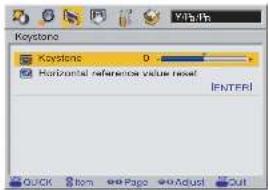
- If the screen is not installed vertically, you can adjust the keystone distortion manually.
- The projector stores the standard conditions of horizontal installation, but depending on the usage environment (if the projector is subject to vibrations or shock, etc.), the standard may change. If the keystone distortion is not properly corrected when the AUTO KEYSTONE button is pressed with the screen installed vertically, set the projector on a flat surface then use the menu screen's "Horizontal reference value reset" function.
Remote control
Control panel
(Main unit side)
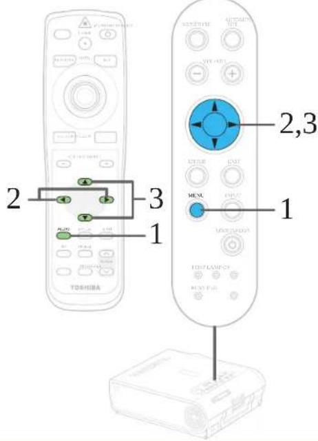
Preparation
1 Project a picture on the screen as explained in the step "Projection on the screen". 28
1


Press MENU twice.
When pressed once, the QUICK MENU screen appears. When pressed twice, the "Picture" screen of the FULL MENU appears.
![QUICK MENU Contrast +5 Brightness 0 Color 0 Keystone 0 Lamp power 11 Input source setting [ENTL1] Language Low [ENTL2] Adjust the contrast of the image. FULL Item 40 Adjust Out](/content/2026/05/759746/images/721008d3262db034e9c1a27e528fd0b25e9f2bdff72442833294969ab0870916.jpg)

![Y/PB/PN Picture Contrast -6 Brightness Color Tint Sharpness Signal format [ENTER] Screen size Full Tint Wide Level QUICK View 00 Page 00 Adjust Quit](/content/2026/05/759746/images/cc1a46d0d7ed7f7fbf8f9255377a525b6b56c31c43b30b331aa625310bb1bf9c.jpg)
2

Use the selection buttons (◀/▶) to display the "Keystone" menu.
3


Use the selection buttons (▲/▼) to select the setting items.
Continued
FULL MENU settings – Keystone (continued)
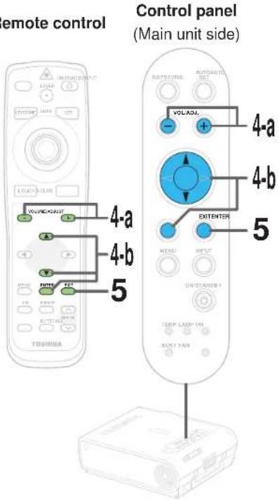
Remote control
When selecting "Keystone" in step 3.
Press VOL/ADJ (+/-) to adjust and set.
Keystone: To reduce the lower width (-) (+) To reduce the upper width
When selecting "Horizontal reference value reset" in step 3.
![graph TD A["4-b"] --> B["ENTER"] B --> C["ENTER"] C --> D["↓"] D --> E["ENTER"] E --> F["▲"] F --> G["▼"] G --> H["↓"] H --> I["ENTER"] I --> J["ENTER"]](/content/2026/05/759746/images/a2c2f9e3c50cb68be0a13209e262e2f83f9697f39fa45743da894ca2d887905a.jpg)
Press ENTER. The sub-menu of "Horizontal reference value reset" appears.
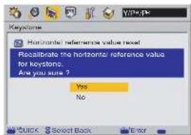
Use the selection buttons (▲ / ▼) to select "Yes" and press ENTER.
The horizontal reference value is reseted.
After the adjustments and settings are finished, press EXIT several times until the menu screen disappears.
Press the EXIT button once when the FULL MENU is displayed, press twice when the sub menu is displayed.
Notes
- If the power is turned off by pressing the ON/STANDBY button, the adjustments or settings made are automatically stored in the memory. If the power cord is unplugged or if a power failure occurs while the projector is on, the adjustments or settings are not stored in the memory.
- The "Keystone" adjustments and settings are applied to all the input sources. (It is impossible to store different adjustments and settings for each input source.)
FULL MENU settings – Display
You can set the language, menu display and start-up screen, etc.

Preparation
1 Project a picture on the screen as explained in the step "Projection on the screen". 28
1


Press MENU twice.
When pressed once, the QUICK MENU screen appears. When pressed twice, the "Picture" screen of the FULL MENU appears.
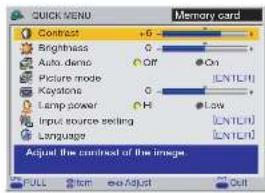

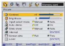
2


Use the selection buttons (◀/▶) to display the "Display" menu.
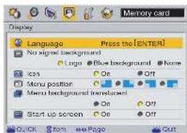
3

Use the selection buttons (▲/▼) to select the setting items.
FULL MENU settings – Display (continued)
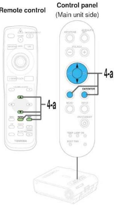
When selecting "Language" in step 3.
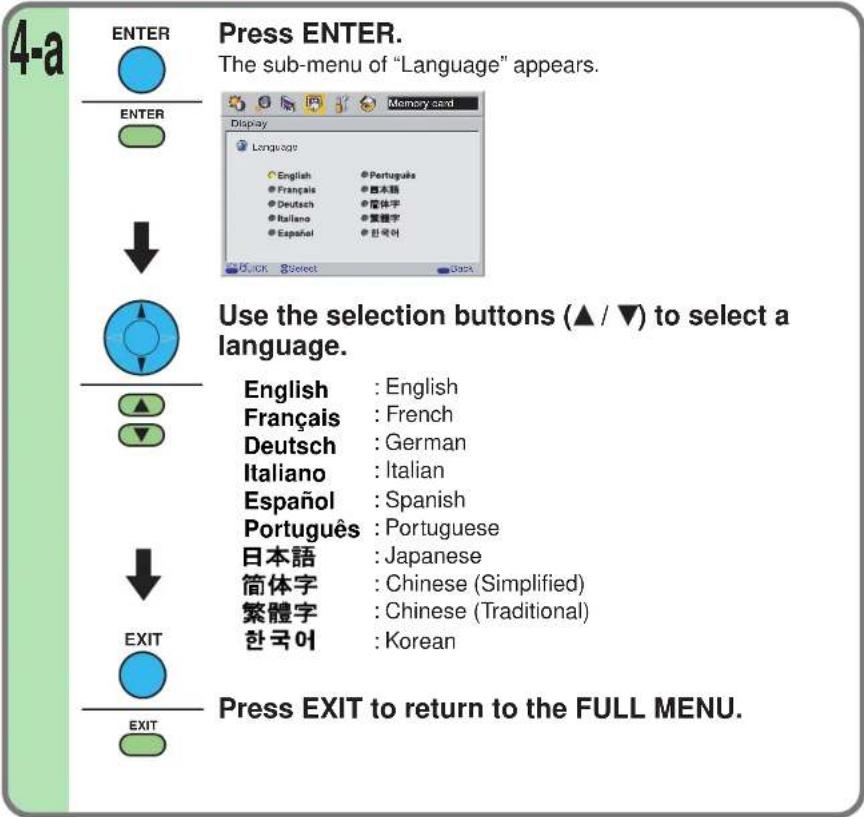
FULL MENU settings – Display (continued)
CONTENTS
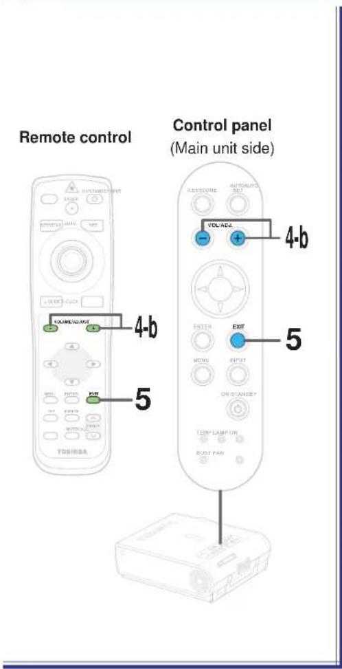
When selecting setting items other than "Language" in step 3.
Press VOL/ADJ (+/-) to adjust and set.
No signal background (Setting of screen of no signal input)
Logo: The TOSHIBA logo screen is displayed.
Blue background: The entire screen is blue.
None: The screen is black.
Icon
When set to "Off", the icons displayed normally when the input is changed or other operations are performed, are no longer displayed.
Menu position
Select the position where the menu is displayed ("Upper left", "Upper right", "Bottom left" or "Bottom right").
Menu background translucent
When set to "On", the menu background becomes translucent.
Start-up screen
When set to "On", the opening screen is displayed when the power is turned on.
After the settings are finished, press EXIT.
The menu screen disappears.
Notes
- If the power is turned off by pressing the ON/STANDBY button, the adjustments or settings made are automatically stored in the memory. If the power cord is unplugged or if a power failure occurs while the projector is on, the adjustments or settings are not stored in the memory.
- The "Display" settings are applied to all the input sources. (It is impossible to store different settings for each input source.)
FULL MENU settings – Default setting
You can set the input source which can be selected by the INPUT button; you can also set the projection mode, power off at no signal status, power on mode and lamp power.
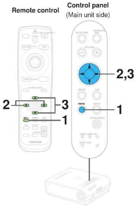
Preparation
1 Project a picture on the screen as explained in the step "Projection on the screen". 28
1


Press MENU twice.
When pressed once, the QUICK MENU screen appears. When pressed twice, the "Picture" screen of the FULL MENU appears.
![QUICK MENU Digital RGB Contrast +6 Brightness 0 Phase Picture mode Keystone Light power Bright True color H Low Input source setting Language [LN ILR] [ENTER] Adjusted the contrast of the image. FULL From Help Adjust Out](/content/2026/05/759746/images/c41c9e27960889b69ef608a795bd55ed00b66b86d90914ec8bb4f7e05c56f70f.jpg)

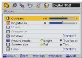
2

Use the selection buttons (◀/▶) to display the "Default setting" menu.
![Digital RGB Default setting Input source setting [ENTC] Lamp power High Low Projection mode [ENTC] No signal power off Out 5 min. Power on Manual Auto Quick Item page Cut](/content/2026/05/759746/images/59201baeca2c102c3a230d4145e66a3d841befd71a142026aee30998baaa3b49.jpg)
3

Use the selection buttons (▲ / ▼) to select the setting items.
FULL MENU settings – Default setting (continued)

When selecting "Input source setting" in step 3. (Set the input that can be selected using INPUT button.)
Remote control
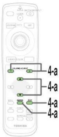
Control panel
(Main unit side)
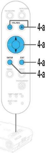
4-a
ENTER

ENTER

-
Press ENTER.
The sub-menu of "Input source setting" appears.
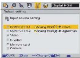
| Menu items | Main unit indication |
| COMPUTER-1 | COMPUTER IN 1 |
| COMPUTER-2 | COMPUTER IN 2 |
| Video | VIDEO |
| S-video | S-VIDEO |
| Memory card | |
| Camera | Document imaging camera(For the model with camera) |
EXIT
Use the selection buttons (▲ / ▼) to select the input source to be set, then press ENTER to check it.
- The check turns on and off each time the ENTER button is pressed.
- When a check box is checked, that input source can be selected by the INPUT button.
(When selecting COMPUTER-1 and COMPUTER-2)
Press VOL/ADJ (+/-) to select the type of input source.
The setting whose button is displayed in yellow is the one currently set.
Press EXIT to return to the FULL MENU.
Notes
- It is impossible to exit from the menu if no input source is selected.
- If the check in the check box for the currently selected source is removed, the setting becomes effective the next time the input is changed.
- For the memory card and document imaging camera, there are modes in which these can be selected even if their check box is not checked. 56 77 Continued
Continued
FULL MENU settings – Default setting (continued)
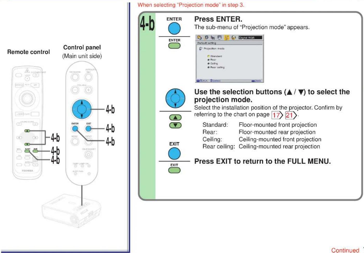
FULL MENU settings – Default setting (continued)
CONTENTS
70
Remote control
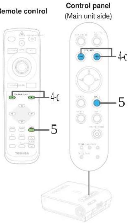
When selecting "No signal power off", "Power on" or "Lamp power" in step 3.
4-c
Press VOL/ADJ (+/-) to set.
No signal power off
OFF: The power does not turn off automatically even if the no signal status continues.
5 min.: The power turns off automatically if the no signal status continues for approx. 5 min.
Power on
Manual: The power turns on by pressing the ON/STANDBY button. Auto: When the power cord is plugged, the power turns on.
Press the ON/STANDBY button when turns power off. 31
Lamp power
Hi: Set the lamp mode with brightness priority. Low: Restrict the lamp output to reduce the cooling sound.
Note
The cooling sound changes according to the temperature inside the projector. When the lamp power setting is changed, the brightness changes immediately, but the cooling sound level does not change immediately.
5
EXIT

EXIT

After the settings are finished, press EXIT.
The menu screen disappears.
Notes
- If the power is turned off by pressing the ON/STANDBY button, the adjustments or settings made are automatically stored in the memory. If the power cord is unplugged or if a power failure occurs while the projector is on, the adjustments or settings are not stored in the memory.
- The settings of "Default setting" are applied to all the input sources. (It is impossible to store different settings for each input source.)
FULL MENU settings – Factory reset mode
You can return the adjusting or setting value to the factory default setting.
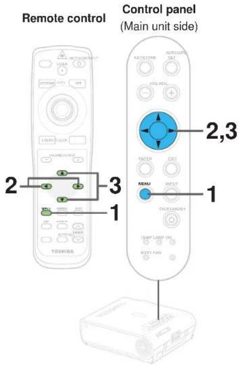
Preparation
1 Project a picture on the screen as explained in the step "Projection on the screen". 28
1
MENU


Press MENU twice.
When pressed once, the QUICK MENU screen appears. When pressed twice, the "Picture" screen of the FULL MENU appears.
![QUICK MENU Camera Contrast +5 Brightness O Shutter 50Hz 60Hz Keystone O Lamp power H Low Input source setting [ENTER] Language [ENTLE] Adjust the contrast of the image FULL Item See Adjust Out](/content/2026/05/759746/images/43cbc7075736e326f8b84923ab7f8a82db941beb06694d64daf0138bba759820.jpg)

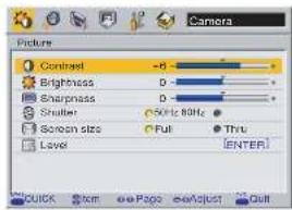
2

Use the selection buttons (◀/▶) to display the "Factory reset mode" menu.
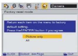
3

Use the selection buttons (▲/▼) to select the setting items.
Picture only: Reset only the adjustments and settings made on the "Picture" menus for the each input to the factory default setting.
All: Reset all the adjustments and settings for all the inputs to the factory default setting.
Continued
FULL MENU settings – Factory reset mode (continued)
Remote control
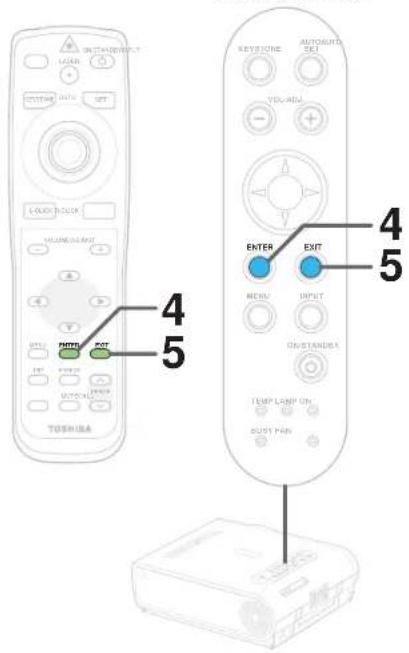
4
ENTER


Press ENTER.
The settings are reset to the factory default settings according to the conditions selected in step 3.
5
EXIT


After the settings are finished, press EXIT.
The menu screen disappears.
Notes
- If the power is turned off by pressing the ON/STANDBY button, the adjustments or settings made are automatically stored in the memory. If the power cord is unplugged or if a power failure occurs while the projector is on, the adjustments or settings are not stored in the memory.
- When the "Factory reset mode" menu is executed, the adjustments and settings for all the inputs return to the factory default settings. (It is impossible to reset them for each input source.)
PIP menu setting
CONTENTS
73
You can make the PIP sub-picture settings and the sound settings when a PIP sub-picture is displayed.
Remote control
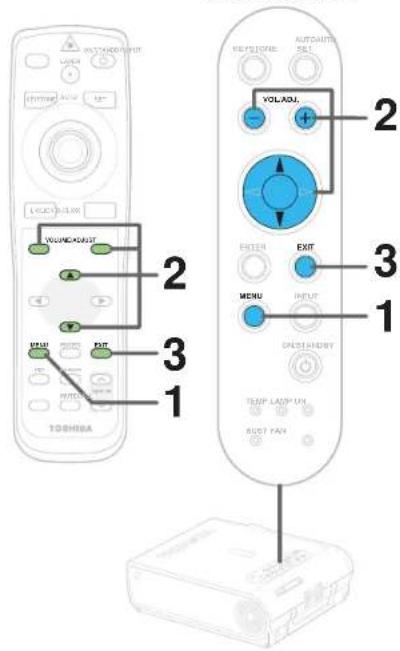
Preparation
1 Display the PIP sub-picture on the screen as explained in the step "Displaying PIP Sub-pictures". 37
1
MENU


Press MENU.
When a PIP sub-picture is displayed, the PIP menu screen appears.
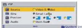
2

Use the selection buttons (▲ / ▼) to select the setting items, then press VOL/ADJ (+/-) to set.
Source: Set the PIP sub-picture input source.
"Video input" or "S-video input" can be selected.
Size: Set the PIP sub-picture size.
"Small" or "Large"
Position: Set the display position of the PIP sub-picture.
"Upper left", "Upper right", "Lower left" or "Lower right"
Audio: Set the audio input source.
The sound of the selected picture ("Main picture" or "Sub-picture") is output from the speakers and the AUDIO OUT jack.
3
EXIT


After the settings are finished, press EXIT.
The menu screen disappears.
Notes
- When the PIP sub-picture is turned off, the audio input source returns to the previous source (main picture).
- If the power is turned off by pressing the ON/STANDBY button, the adjustments or settings made are automatically stored in the memory. If the power cord is unplugged or if a power failure occurs while the projector is on, the adjustments or settings are not stored in the memory.
Part names (of the document imaging camera model)
CAUTION
When using the camera, be careful to not pinch your hand or fingers into the arm.
On the document imaging camera model, you can project pictures using the document imaging camera. The document imaging camera can directly project any materials (documents, illustrations, etc.) without using an OHP film.
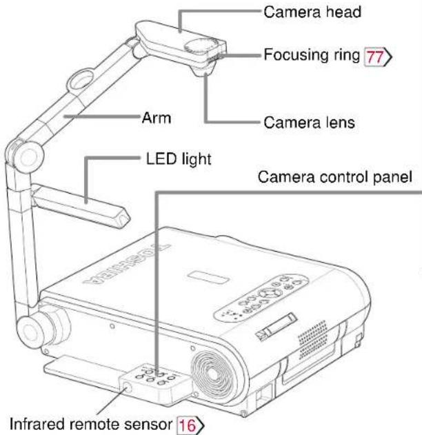
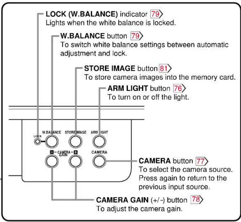
Preparation of the document imaging camera
Before preparations(stowed away)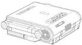 | 1) Raise up the arm.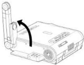 | 2) Stretch the arm. 3) Turn the arm.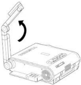 | 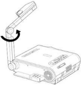 |
4) Open the camera head. 5) Turn the camera head.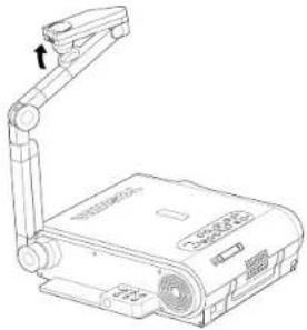 | 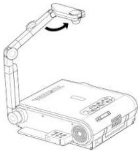 | 6) Pull up the light.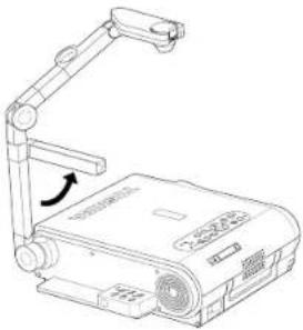 | 7) Turn the light.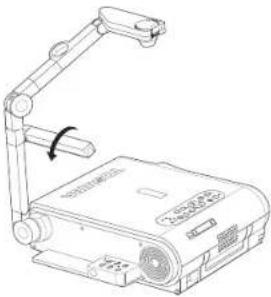 |
Notes
- Never give shocks or impacts to the camera or arm as this may cause malfunction.
- While raising up or turning the arm, the arm moves describing an arc, be careful not to hit your face or your body.
Picture projection with the document imaging camera

CAUTION
Do not look into the arm light while it is lit.
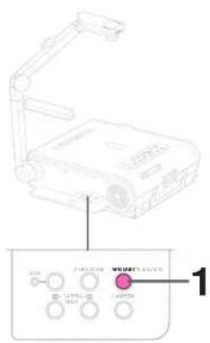
Camera control panel
Preparation
1 Project a picture on the screen as explained in the step "Projection on the screen". 28
1
ARM LIGHT

Press ARM LIGHT.
The light turns on.
2
Set a document to be projected.
Place the document (illustrations, etc.) onto or around the projector, and turn the camera head to the direction of the document.
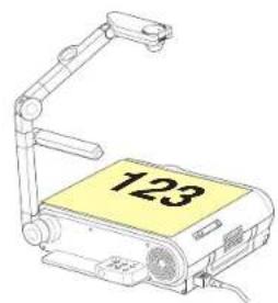
Images on the screen
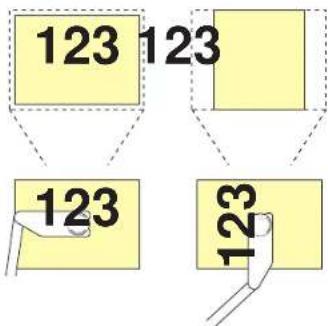
Setting direction
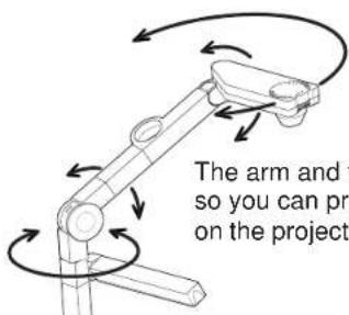
The arm and the camera head can be moved freely, so you can project the document if it is not placed on the projector.
Picture projection with the document imaging camera (continued)
Remote control
Control panel
(Main unit side)
3
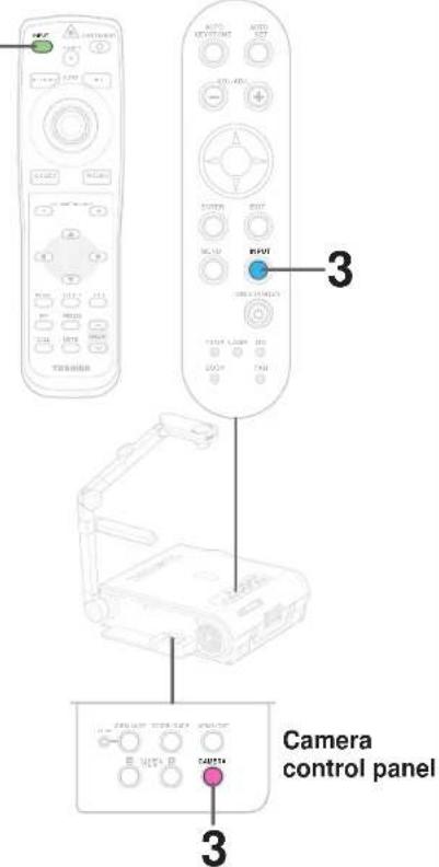
3

INPUT

INPUT

Press CAMERA to select the camera input mode.
- You can also select it by pressing INPUT on the remote control or on the main unit. Set the input source on the menu screen when selecting by the INPUT button. 54
- The CAMERA button can be used regardless of the input setting.
- "Camera" is displayed when the picture switches to the document imaging camera's picture.
4
Move the camera head to adjust the size of the picture.
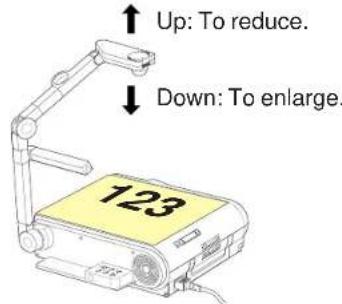
5
Focus on the picture by turning the focusing ring on the camera head.
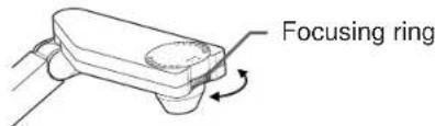
Continued
Picture projection with the document imaging camera (continued)
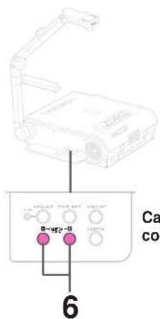
Camera control panel
6
— CAMERA
GAIN

A—+
-

Press CAMERA GAIN (+/-) to improve view of a camera subject which is too dark or vivid.
Notes
- You can adjust the "Sharpness" of the camera image on the menu screen. 54
- If the image flickers due to a fluorescent light in the room, either turn off the fluorescent light or set the "Shutter" from the menu screen. 54
Note that the image may still flicker due to the lighting, the document status, the image adjustment, etc., even if the "Shutter" setting is changed.
7
When finished, turn off the light and close it, and put back the arm.
Follow the steps of "Preparation of the document imaging camera" in reverse.
Notes
- Though this projector uses a 1.45 million pixel camera unit, the images projected on the screen are 1024 × 768 dot images. If the "Screen size" in the menu screen 54 is set to "Full", the camera's full image is compressed to 1024 × 768 dots. If "Thru" is selected, the 1024 × 768 dots at the center of the image are projected.
• The light turns off automatically when the arm is leaned. - When the arm is not raised up, the camera source cannot be projected.
- In the camera input selected, audio signals are not output.
Lock the white balance

Normally, this camera automatically adjusts the color balance to project the picture. If the adjustment is not sufficient, follow the steps below to lock the white balance.
1
Project a white paper and enlarge it to fill the screen.
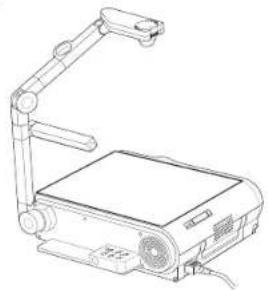
2
LOCK—W.BALANCE


Press W.BALANCE to turn the LOCK indicator on.
The white balance is locked.
To release the white balance, press W.BALANCE again to turn the LOCK indicator off.
Notes
- If you raise up the arm while the camera input is selected, the color of the picture may vary for an instant due to the automatic white balance adjustment. This is not a malfunction.
- If you put back the arm and raise it up while the white balance is locked (the LOCK indicator is lit), the projector releases the white balance.
Correcting illuminated defects
80
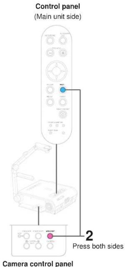
For the CCD image sensor used in the camera unit, in rare cases some of the pixels may be disturbed due to the influence of cosmic rays, etc. This disturbance may cause white spots to appear on the picture.
If white spots appear on the document camera image, use the procedure described below to correct it.
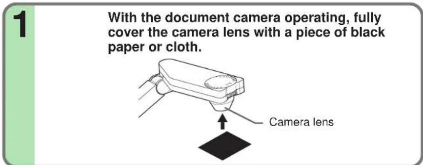
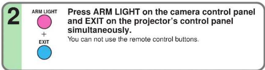
imaging camera
Document
Note
Do not press ARM LIGHT and EXIT buttons simultaneously if the camera lens is not covered. Doing so will not only erase the white spot correction data already set but also result in parts that are displayed normally being corrected. Also be careful if the camera input mode is not selected.
Store the camera images into the memory card
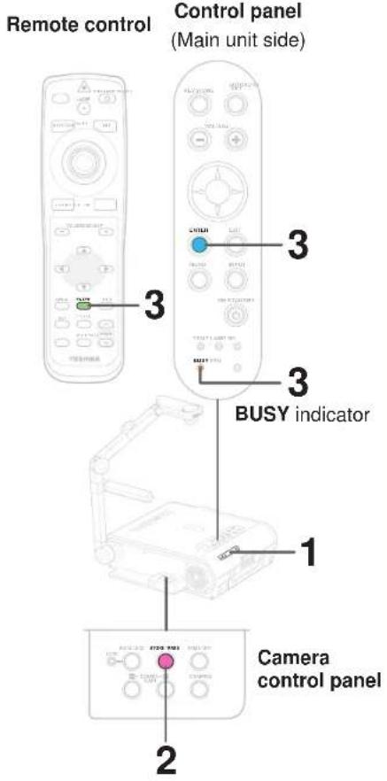
Document camera images can be stored on memory cards.
1 Insert a memory card into the card slot. 41
If the memory card "Input select mode" is set to "Auto.", the mode switches to the memory card input mode. If so, press the CAMERA button to return to the document imaging camera input mode.
2
STORE IMAGE

Project the camera image you want to store on the cards, then press STORE IMAGE in the camera control panel.
A message asking you to confirm that you want to store the image appears.
3
ENTER
BUSY


ENTER


The icon 📋 appears when the memory card is in the storing mode.
Notes
- If the "Screen size" in the menu screen 54 is set to "Full", the camera's full image is compressed to 1280 x 960 dots before it is stored. If it is set to "Thru", only the 1024 x 768 dots at the center of the image are stored.
- The "Camera gain" and "Sharpness" settings are reflected on the images stored on memory cards; "Contrast" and "Brightness" settings are not.
- It is impossible to store resized or frozen images on memory cards.
- The image data is stored as JPEG format files in the memory card's "_tlpx" folder. If there is no "_tlpx" folder, one is created in the memory card's root directory. Stored files are named "Tlpx001.jpg" to "Tlpx999.jpg". If there is already a file named "Tlpx999.jpg" in the folder, no more images can be stored.
- The size of stored files depends on the content of the image. The number of files that can be stored on a memory card depends on the size of the files and the amount of free space of the memory card.
- Do not save the camera image when the memory card is in the write-protect mode. The memory card may not be accessed.
Trouble indications

If there is some problem inside the projector, the indicators light up or blink.
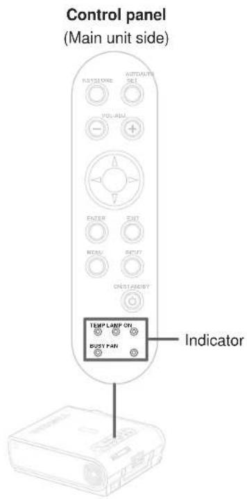
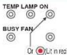 | The power does not come on.→ Malfunction of the unit.• Unplug the power cord and call the dealer. |
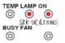 | The lamp turns off or does not light up.→ The lamp's duration life is end, or malfunction of the unit.Lamp's duration life is over, replace the lamp with a new one.86Unplug the power cord and call the dealer. |
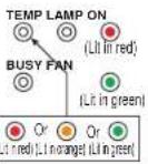 | The power turns off or does not come on.→ The inside is too hot, or the projector has been working in an area of high temperature.Place the projector correctly so the intake and exhaust fans' holes are not covered.Turn the projector off, and leave it for a while, and turn it on again.Clean the air filter.83* The iconappears before the power turned off. |
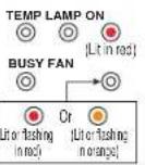 | The power turns off or does not come on.→ Trouble with the cooling fan.Unplug the power cord and call the dealer.* The iconappears before the power turned off. |
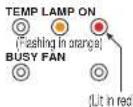 | The power turns off or does not come on.→ The lamp cover is not properly attached.Unplug the power cord and reattach the lamp cover.87* The iconappears before the power turned off. |
Note
If abnormality occurs while operating, unplug the power cord.
Air filter cleaning
CONTENTS
83
CAUTION
If you use the projector mounted on the ceiling, ask the dealer to carry out the maintenance such as cleaning.
The filter inside the air filter cover is the part to shut out dusts or dregs.
Do not use the projector with the filter taken off.
We recommend you to clean the air filter frequently. (The cleaning period is once per about 50 hours).
1 Unplug the power cord.
Take off the air filter cover.
The filter is on the right side of the projector. Pull the bottom side of the cover upward to remove the filter cover.
3 Detach the air filter.
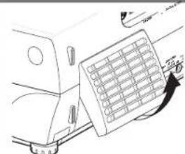
Detach the air filter from the air filter cover.
The air filter cover, air filter and filter frame can be disassembled.
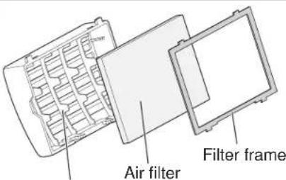
Air filter cover
1 Clean the air filter.
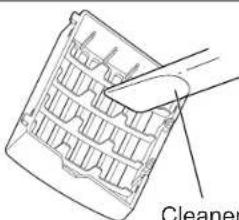
Use a vacuum cleaner to carefully remove any dust and dirt from the air filter cover, air filter and filter frame.
Be careful that the air filter is not sucked into the vacuum cleaner.
Cleaner's nozzle
Continued
Air filter cleaning (continued)

Notes
- When the air filter is dusty, the ventilation is impaired. This causes the temperature inside the projector to rise, and may damage the unit.
- Attach the air filter cover firmly after the cleaning. If it is not set correctly, the dusts will enter and they will be projected and overlapped on the picture.
- If you wash the air filter with water, be sure to let it dry fully before reinstalling it. Using it damp will result in malfunction.
- If the air filter is damaged, contact your store of purchase and replace it with a new one. Using a damaged air filter will cause dust or dirt to get inside the projector and onto the images.
5
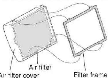
Assemble the air filter.
Place the air filter in the air filter cover, then insert the four tabs on the filter frame into the holes in the air filter cover.
6
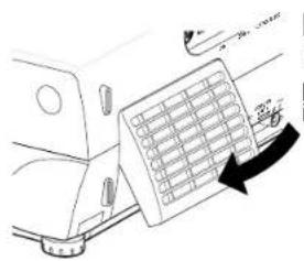
Mount the air filter cover.
Insert the top of the air filter cover into the projector first, then press on the bottom side to install it.
Lens and main unit cleaning

CAUTION
If you use the projector mounted on the ceiling, ask the dealer to carry out the maintenance such as cleaning.
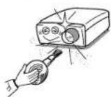
Cleaning the lens
Use a blower or a lens cleaner to clean the lens. Never rub or tap the lens with a hard object as the lens surface is fragile.
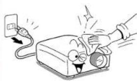
Cleaning the main unit
- Pull out the power cord before cleaning.
- Use a soft cloth to wipe off stains from the surface.
• To remove difficult stains, use a soft cloth slightly moistened with a weak solution of synthetic detergent and water, and finish with a soft, dry cloth.
Replacing the intake, exhaust fans and air filter
To maintain the efficiency of the projector, replace the intake and exhaust fans about every two to three years. Ask the dealer for the replacement.
Lamp replacement

The lamp will eventually begin to project dark or dull pictures and finally will not light up. (Lamp's life length depends on the use condition.) In such a case, replace the lamp with new one.
CAUTION
- If you use the projector mounted on the ceiling, ask the dealer to carry out the maintenance such as cleaning or replacement of the lamp.
- When replacing, always use lamp "TLPLX10" (sold separately). For detail, refer to the lamp instruction.
- If you have been using the projector, the lamp will be very hot, and may cause burn injuries. Wait for the lamp to cool (for longer than 1 hour) before replacing it.
- If the lamp should break, please handle with care to avoid injury due to broken pieces and contact your dealer for repair service.
1 Unplug the power cord.
2 Wait until the lamp gets cold enough.
Take off the bottom panel
Loosen two screw cover.
Lamp cover
4
Pull out the lamp.
Loosen the two fixing screws, and lift up the handle to pull out the lamp.
Lamp replacement (continued)
Notes
- When the CALL button is pressed, the "Lamp time" (the approximate amount of time the lamp has been used) is displayed. 38
- The lamp should be replaced if the total working time exceeds about 1,000 hours.
When the "Lamp time" is displayed 1000 hours,
the icon and a message appear. They will disappear when you do some operation.
- Attach the lamp cover firmly after replacing the lamp. If it is not set correctly, the power will not turn on.
- Use a new lamp when replacing it.
- The lamp is made of glass and is very fragile. Do not touch the lamp with your bare hands and do not jolt or damage it. Do not use an exhausted lamp.
- Dispose the exhausted lamp as toxic wastes.
5 Load a new lamp.
Slide until it hits the bottom and tighten the two fixed screws.
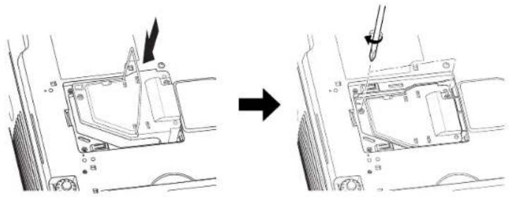
6
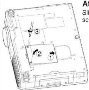
Attach the lamp cover.
Slide the cover in place and tighten two screws.
7 Reset the lamp timer.
Refer to the lamp instructions for resetting.
Before calling service personal

Check the following points before asking for support service. Refer also to "Trouble indications" 82
| Symptom | Cause | Correction | Page |
| The power does not come on. | • The power cord is disconnected. | Firmly plug in the power cord. | 19 |
| • The lamp cover is not attached correctly. | Attach the cover correctly. | 87 | |
| The power turns off while using the projector. | • The ambient temperature of the projection room is too high. | Lower the ambient temperature of the projection room, and turn the power on. | 82 |
| No image appears. | • The lens cover is on. | Take off the lens cover. | 19 |
| • The wrong input is selected. | Select the input source correctly. | 29 | |
| • The muting mode is on. | Press MUTE to restore the picture. | 34 | |
| • The "Brightness" adjustment is at its darkest. | Make the "Brightness" adjustment. | 48 | |
| • The source is not correctly connected to the projector. | Connect the source correctly to the projector. | 22 | |
| No sound is heard. | • The wrong input is selected. | Select the input source correctly. | 29 |
| • The muting mode is on. | Press MUTE to restore the sound. | 34 | |
| • The sound volume is at the minimum. | Adjust the sound volume. | 12 | |
| • The source is not correctly connected to the projector. | Connect the source correctly to the projector. | 22 | |
| Desired input source cannot be selected by the INPUT button. | • Input is not set so that it can be selected with the INPUT button. By default, only the RGB1 and video input modes can be selected. | Set from the menu screen so that the source can be selected with the INPUT button. | 48 |
| RGB1 input or Y/PB/PR input colors are not right. | • The COMPUTER IN 1 connector's input setting is wrong. | At the menu screen, set for the proper input signal type. | 48 |
| RGB2 input image does not appear. | • The COMPUTER IN 2 connector's input setting is wrong. | At the menu screen, set for the proper input signal type. | 48 |
| • The signal cable type is wrong. | Use a proper signal cable. | 23 | |
| Digital RGB input image does not appear. | • The COMPUTER IN 2 connector's input setting is wrong. | At the menu screen, set for the proper input signal type. | 48 |
| • The signal cable type is wrong. | Use a proper signal cable. | 23 | |
| The image is blurred. Focusing is uneven. | • The lens is dirty. | Clean the lens with a blower or lens cleaner, etc. | 85 |
| • The picture is out of focus. | Focus the picture. | 30 | |
| • The projection distance is not appropriate. | Adjust the distance properly. | 18 | |
| • The projecting light is not hitting the screen squarely. | Adjust the projecting direction so that the light hits the screen squarely. | 18 | |
| • The "Brightness", "Contrast", "Sharpness" or "Phase" adjustments are not correct. | Make the "Picture" adjustments. | 54 | |
| The picture is dim. | • The "Brightness" or "Contrast" adjustments are not correct. | Make the "Picture" adjustments. | 54 |
| • The lamp life is ending. | Replace the lamp. | 86 |
Before calling service personal (continued)

| Symptom | Cause | Correction | Page |
| The color is faint.The tint is not good. | • The “Color”, “Tint”, “R-Level”, “G-Level” or “B-Level” adjustments are not correct. | Make the “Picture” adjustments. | 54 |
| • The lamp life is ending. | Replace the lamp. | 85 | |
| The remote control does not work. | • The remote control is not facing the remote sensor. | Face the remote control transmitter toward the remote sensor on the projector. | 16 |
| • The remote control is too far. | Operate within about 5 meters. | 16 | |
| • There is an obstruction between the remote control and the remote sensor. | Remove the obstacle. | - | |
| • The batteries are exhausted. | Replace the batteries. | 15 | |
| Image data on a memory card cannot be displayed. | • No memory card is inserted. | Insert the memory card properly. | 41 |
| • A different type of memory card is inserted. | Replace with a compatible memory card. | 40 | |
| • There are no JPEG files on the memory card. | Check using the thumbnail display. | 42 | |
| • The JPEG files have been created with an incompatible compression format. | Convert JPEG files to a compatible compression format. | - | |
| Mouse function cannot be used from the remote control unit. | • The USB cable is not properly connected. | Connect the USB cable properly. | 39 |
| • The computer or OS is not compatible. | The remote control mouse function is not available. | - | |
| • The batteries are exhausted. | Replace the batteries. | 15 | |
| Document camera image is blurry. | • The lens is dirty. | Clean the lens with a blower or lens cleaner, etc. | 85 |
| • The picture is out of focus. | Focus the picture by turning the focus ring. | 77 | |
| • The light is not on. | Turn on the light. | 76 | |
| Document camera image flickers. | • Image is being affected by fluorescent light in the room. | Set the shutter speed on the menu screen. | 54 |
| Document camera image movement is awkward. | • The image’s number of frames is low. This is not a malfunction. | ||
| Horizontal stripes appear when document projected with the document camera is moved. | • The image’s number of frames is low. This is not a malfunction. |
Pin assignment of COMPUTER IN, MONITOR OUT connector

90
COMPUTER IN 1
MONITOR OUT
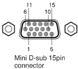
Input signal
Analog R, G, B signal: 0.7V(p-p) 75Ω
Horizontal sync signal:
TTL level (positive/negative polarity)
Vertical sync signal:
TTL level (positive/negative polarity)
Y signal: 1.0V(p-p) 75Ω
PB , PR signal: 0.7V(p-p) 75Ω
COMPUTER IN 2
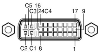
DVI ANALOG & DIGITAL connector
Analog input signal
Analog R, G, B signal: 0.7V(p-p) 75Ω
Horizontal sync signal:
TTL level (positive/negative polarity)
Vertical sync signal:
TTL level (positive/negative polarity)
| Pin No. | Description | |
| RGB input | Y/PB/PR input | |
| 1 | Video signal (Red) | Color difference signal ( PR ) |
| 2 | Video signal (Green) | Luminance signal (Y) |
| 3 | Video signal (Blue) | Color difference signal ( PB ) |
| 4 | GND | * |
| 5 | GND | * |
| 6 | GND (Red) | GND ( PR ) |
| 7 | GND (Green) | GND (Y) |
| 8 | GND (Blue) | GND ( PB ) |
| 9 | N.C | * |
| 10 | GND | * |
| 11 | GND | * |
| 12 | DDC2B data | * |
| 13 | Horizontal sync signal | * |
| 14 | Vertical sync signal | * |
| 15 | DDC2B clock | * |
| Pin No. | Description |
| 1 | T.M.D.S. data 2- |
| 2 | T.M.D.S. data 2 + |
| 3 | T.M.D.S. data 2/4 shield |
| 4 | T.M.D.S. data 4- |
| 5 | T.M.D.S. data 4 + |
| 6 | DDC clock |
| 7 | DDC data |
| 8 | Analog vertical sync signal |
| 9 | T.M.D.S. data 1- |
| 10 | T.M.D.S. data 1 + |
| 11 | T.M.D.S. data 1/3 shield |
| 12 | T.M.D.S. data 3- |
| 13 | T.M.D.S. data 3 + |
| 14 | +5V power |
| 15 | GND (+5V, H Sync & V Sync) |
| Pin No. | Description |
| 16 | Hot plug detection |
| 17 | T.M.D.S. data 0- |
| 18 | T.M.D.S. data 0 + |
| 19 | T.M.D.S. data 0/5 shield |
| 20 | T.M.D.S. data 5- |
| 21 | T.M.D.S. data 5 + |
| 22 | T.M.D.S. clock shield |
| 23 | T.M.D.S. clock + |
| 24 | T.M.D.S. clock- |
| C1 | Analog Video signal (Red) |
| C2 | Analog Video signal (Green) |
| C3 | Analog Video signal (Blue) |
| C4 | Analog horizontal sync signal |
| C5 | Analog GND (R,G & B) |
*: Do not connect anything.
Applicable signal
Applicable RGB signal
The unit is applicable to the following signals. However, some computers may have different timings than those in the chart. Make the necessary adjustments if the picture has flickers or is blurred.
Signal Timing (Horizontal)
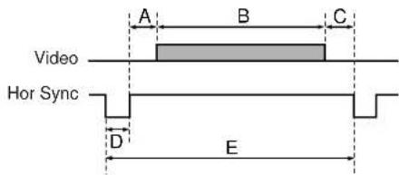
Signal Timing (Vertical)
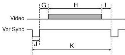
Timing chart
| Mode | Resolution | A(Pixels) | B(Pixels) | C(Pixels) | D(Pixels) | E(Pixels) | fh(kHz) | fv(Hz) | Clock(MHz) | G(Lines) | H(Lines) | I(Lines) | J(Lines) | K(Lines) |
| TEXT70 640 x 350 50 640 | 14 96 800 31.469 | 70.086 | 25.175 | 59 350 38 | 2 449 | |||||||||
| TEXT70 640 x 400 50 640 | 14 96 800 31.469 | 70.086 | 25.175 | 34 400 13 | 2 449 | |||||||||
| TEXT85 640 x 350 96 640 | 32 64 832 37.861 | 85.080 | 31.500 | 60 350 32 | 3 445 | |||||||||
| TEXT85 640 x 400 96 640 | 32 64 832 37.861 | 85.080 | 31.500 | 41 400 1 | 3 445 | |||||||||
| NEC PC98 24k 640 x 400 | 85 640 59 64 848 | 24.820 | 55.900 | 21.047 25 | 400 11 8 | 444 | ||||||||
| VGA60 640 x 480 48 640 | 16 96 800 31.469 | 59.940 | 25.175 | 33 480 10 | 2 525 | |||||||||
| VGA72 640 x 480 128 640 | 24 40 832 37.861 | 72.809 | 31.500 | 28 480 9 | 3 520 | |||||||||
| VGA75 640 x 480 120 640 | 16 64 840 37.500 | 75.000 | 31.500 | 16 480 1 | 3 500 | |||||||||
| VGA85 640 x 480 80 640 | 56 56 832 43.269 | 85.008 | 36.000 | 25 480 1 3 | 509 | |||||||||
| MAC13" 640 x 480 96 640 | 64 64 864 35.000 | 66.667 | 30.240 | 39 480 3 | 3 525 | |||||||||
| SVGA56 800 x 600 128 | 800 24 72 1024 | 35.156 56. | 250 36.000 | 22 600 | 1 2 625 | |||||||||
| SVGA60 | 800 x 600 | 88 | 800 | 40 | 128 | 1056 | 37.879 | 60.317 | 40.000 | 23 | 600 | 1 | 4 | 628 |
| SVGA72 800 x 600 64 800 | 56 120 | 1040 | 48.077 | 72.188 | 50.000 23 | 600 37 6 | 666 | |||||||
| SVGA75 800 x 600 160 | 800 16 80 | 1056 | 46.875 | 75.000 | 21 600 | 1 3 625 | ||||||||
| SVGA85 800 x 600 152 | 800 32 64 | 1048 | 53.674 | 85.061 | 27 600 | 1 3 631 | ||||||||
| MAC16" 832 x 624 216 | 832 40 64 | 1152 | 49.725 | 74.550 | 39 632 | 1 3 667 | ||||||||
| XGA43i | 1024 x 768 | 56 | 1024 | 8 | 176 | 1264 | 35.522 | 43.479 | 44.900 | 20 | 768 | 0 | 4 | 817 |
| XGA60 | 1024 x 768 | 160 | 1024 | 24 | 136 | 1344 | 48.363 | 60.004 | 65.000 | 29 | 768 | 3 | 6 | 806 |
| XGA70 | 1024 x 768 | 144 | 1024 | 24 | 136 | 1328 | 56.476 | 70.069 | 75.000 | 29 | 768 | 3 | 6 | 806 |
| XGA75 | 1024 x 768 | 176 | 1024 | 16 | 96 | 1312 | 60.023 | 75.029 | 78.750 | 28 | 768 | 1 | 3 | 800 |
| XGA85 | 1024 x 768 | 208 | 1024 | 48 | 96 | 1376 | 68.677 | 84.997 | 94.500 | 36 | 768 | 1 | 3 | 808 |
| MAC19" | 1024 x 768 | 180 | 1024 | 20 | 96 | 1320 | 60.197 | 74.872 | 73.200 | 30 | 768 | 3 | 3 | 804 |
Applicable signal (continued)

Timing chart (Continued)
| Mode | Resolution | A(Pixels) | B(Pixels) | C(Pixels) | D(Pixels) | E(Pixels) | fh(kHz) | fv(Hz) | Clock(MHz) | G(Lines) | H(Lines) | I(Lines) | J(Lines) | K(Lines) |
| *SXGA1152x864 75Hz 1 | 152 x 864 256 11 | 52 64 128 | 1600 67 | .500 75.00 | 00 108.0 | 00 32 86 | 4 1 3 900 | |||||||
| *SXGA1280x960 60Hz 1 | 280 x 960 312 12 | 80 96 112 | 1800 60 | .000 60.00 | 00 108.0 | 00 36 96 | 0 1 3 1000 | |||||||
| *SXGA1280x960 85Hz 1 | 280 x 960 224 12 | 80 64 160 | 1728 85 | .938 85.00 | 02 148.5 | 00 47 96 | 0 1 3 1011 | |||||||
| *SXGA1280x1024 60Hz | 1280 x 1024 248 | 1280 48 | 112 1688 | 63.981 60 | 0.020 108 | 8.000 38 | 1024 1 3 | 1066 | ||||||
| *SXGA1280x1024 75Hz | 1280 x 1024 248 | 1280 16 | 144 1688 | 79.976 75 | 5.025 135 | 5.000 38 | 1024 1 3 | 1066 | ||||||
| *SXGA1280x1024 85Hz | 1280 x 1024 224 | 1280 64 | 160 1728 | 91.146 85 | 5.024 157 | 7.500 44 | 1024 1 3 | 1072 | ||||||
| *UXGA60 1600 x 1200 30 | 4 1600 64 192 2 | 160 75.00 | 00 60.000 | 162.000 | 46 1200 | 1 3 1250 | ||||||||
| *UXGA65 1600 x 1200 30 | 4 1600 64 192 2 | 160 81.25 | 50 65.000 | 175.500 | 46 1200 | 1 3 1250 | ||||||||
| *UXGA70 1600 x 1200 30 | 4 1600 64 192 2 | 160 87.50 | 00 70.000 | 189.000 | 46 1200 | 1 3 1250 | ||||||||
| *UXGA75 1600 x 1200 30 | 4 1600 64 192 2 | 160 93.75 | 50 75.000 | 202.500 | 46 1200 | 1 3 1250 |
Notes
- Signal sources marked “*” are displayed in compressed format, so some of their data may be missing or their picture quality may be degraded.
- With analog RGB input, if the signal source's dot clock frequency exceeds 140 MHz, not all of the pixel signals can be sampled.
- For digital RGB inputs, the projector is not compatible with signal sources whose dot clock frequency exceeds 112 MHz.
The compatible video signal
| Mode | fh (kHz) | fv (Hz) | fsc (MHz) |
| NTSC | 15.73 | 60 | 3.58 |
| PAL | 15.63 | 50 | 4.43 |
| SECAM | 15.63 | 50 | 4.25 or 4.41 |
| PAL-M | 15.73 | 60 | 3.58 |
| PAL-N | 15.63 | 50 | 3.58 |
| PAL-60 | 15.73 | 60 | 4.43 |
| NTSC4.43 | 15.73 | 60 | 4.43 |
The compatible component signal (Y/PB/PR)
| Mode | fh (kHz) | fv (Hz) |
| 480i | 15.73 | 59.94 |
| 480p | 31.47 | 59.94 |
| 720p | 45.00 | 60.00 |
| 1080i | 33.75 | 60.00 |
Controlling the projector by using RS-232C

You can also control the projector by entering the command from a computer via RS-232C.
Signal assignment of RS-232C
| Pin No. | Signal | Description |
| 1 | RXD | Receiving data |
| 2 | CTS | Consent to send |
| 3 | DSR | Data set ready |
| 4 | GND | Signal ground |
| 5 | RTS | Request to send |
| 6 | N.C | No connection |
| 7 | TXD | Sending data |
| 8 | N.C | No connection |
Interface format
| 1 | Communication method | RS-232C9600 bps, No parity, Data length: 8 bit,Stop bit: 1 bit | ||
| 2 | Communication format | STX (02h) | Command (3Byte) | ETX (03h) |
| One command only can be used in one communication. | ||||
| 3 | Data format | Command shall be composed of alphanumeric characters of ASCII description.Use only capital letters. | ||
| 4 | Return value | Acknowledge | ACK (06h) | |
| Not Acknowledge | NAK (15h) | |||
Command list
| Classification | Digital Status | Selection Command | Adjustment Command | Analog RGB1 Analog RGB2 | Video S-video | Y/PB/PR | Memory Card | Document Imaging Camera | ||
| Power On | PON | - | O | O | O | O | O | O | ||
| Off (with confirmation message) | POF | - | O | O | O | O | O | O | ||
| Shut Down (without confirmation message) | PSD | - | O | O | O | O | O | O | ||
| Normal (RS-232C Condition Display Off) | DOF | - | O | O | O | O | O | O | ||
| Picture Contrast | VCN | O | O | O | O | O | O | O | ||
| VBR | O | O | O | O | O | O | O | |||
| PPH | O | O | - | - | - | |||||
| PCK | O | O | - | - | - | |||||
| VCL | O | - | - | O | O | - | - | |||
| VTN | O | - | - | O*1 | O*2 | - | - | |||
| VSH | O | - | - | O | O*2 | - | - | |||
| CS0 | - | - | - | - | - | - | O | |||
| CS1 | - | - | - | - | - | - | O | |||
Notes
- When commands are transmitted serially, keep more than 100 ms intervals between the commands.
- Adjustment commands include "ARG" (increase adjustment value) and "ALF" (decrease adjustment value). For usable items (marked "O"), send after the selection command.
- The “O” marks in the input source columns indicate that that command can be used. *1 Not possible for PAL/SECAM. *2 Not possible for 480i mode.
Continued
Controlling the projector by using RS-232C (continued)

94
| Classification | Digital Status | Selection Command | Adjustment Command | Analog RGB1 Analog RGB2 | Video S-video | Y/PB/PR | Memory Card | Document Imaging Camera | ||
| Picture Position H-position | PHP | O | O | - | - | - | - | - | ||
| V-position | PVP | O | O | - | - | - | - | - | ||
| Picture mode Bright | MVB | - | O | O | - | - | - | |||
| True color | MVP | - | O | O | - | - | - | |||
| Video mode Auto. | KV0 | - | - | - | O | - | - | |||
| NTSC | KV1 | - | - | - | O | - | - | |||
| PAL | KV2 | - | - | - | O | - | - | |||
| SECAM | KV3 | - | - | - | O | - | - | |||
| PAL-N | KV4 | - | - | - | O | - | - | |||
| PAL-M | KV5 | - | - | - | O | - | - | |||
| PAL60 | KV6 | - | - | - | O | - | - | |||
| NTSC4.43 | KV7 | - | - | - | O | - | - | |||
| Signal format Auto. | SG0 | - | - | - | - | O | - | |||
| 480i | SG1 | - | - | - | - | O | - | |||
| 480p | SG2 | - | - | - | - | O | - | |||
| 720p | SG3 | - | - | - | - | O | - | |||
| 1080i | SG4 | - | - | - | - | O | - | |||
| Input Select mode Manual | JI0 | - | - | - | - | - | O | |||
| Auto. | JI1 | - | - | - | - | O | ||||
| Auto. demo Off | JD0 | - | - | - | - | - | O | |||
| On | JD1 | - | - | - | - | - | O | |||
| Slide show Manual | JS0 | - | - | - | - | - | O | |||
| Auto. | JS1 | - | - | - | - | O | ||||
| Interval 10 sec. | JT0 | - | - | - | - | - | O | |||
| 30 sec. | JT1 | - | - | - | - | - | O | |||
| 3 min. | JT2 | - | - | - | - | - | O | |||
| 10 min. | JT3 | - | - | - | - | - | O | |||
| Screen size Full | MSF | - | O | O | O | O | O | |||
| Thru | MST | - | O | O | O | O | O | |||
| Wide | MSW | - | - | - | O | O | - | |||
| Level | R-level | VLR | O | O | O | O | O | O | ||
| G-level | VLG | O | O | O | O | O | O | |||
| B-level | VLB | O | O | O | O | O | O | |||
Controlling the projector by using RS-232C (continued)

| Classification | Digital Status | Selection Command | Adjustment Command | Analog RGB1 Analog RGB2 | Video S-video | Y/PB/PR | Memory Card | Document Imaging Camera | ||
| Audio Speaker output On | AS1 | - | O | O | O | O | - | - | ||
| Off | AS0 | - | O | O | O | O | - | - | ||
| Channel select (RCA) L+R | APA | - | - | - | O | - | - | - | ||
| APL | - | - | - | O | - | - | - | |||
| APR | - | - | - | O | - | - | - | |||
| Loudness (RCA) Off | LR0 | - | - | O | - | - | - | |||
| On | LR1 | - | - | O | - | - | - | |||
| Channel select (Mini) L+R | AMA | - | O | O | - | O | - | - | ||
| AML | - | O | O | - | O | - | - | |||
| AMR | - | O | O | - | O | - | - | |||
| Loudness (Mini) Off | LM0 | - | O | O | - | O | - | |||
| On | LM1 | - | O | O | - | O | - | |||
| Keystone Keystone | PKS | O | O | O | O | O | O | O | ||
| Horizontal reference value reset | PKR | - | O | O | O | O | O | |||
| Display Language English | LEN | - | O | O | O | O | O | O | ||
| French | LFR | - | O | O | O | O | O | |||
| German | LGR | - | O | O | O | O | O | |||
| Italian | LIT | - | O | O | O | O | O | |||
| Spanish | LSP | - | O | O | O | O | O | |||
| Portuguese | LPO | - | O | O | O | O | O | |||
| Japanese | LJP | - | O | O | O | O | O | |||
| Chinese(Simplified) | LPK | - | O | O | O | O | O | |||
| Chinese(Traditional) | LKT | - | O | O | O | O | O | |||
| Korean | LKK | - | O | O | O | O | O | |||
| Logo | BG0 | - | O | O | O | O | O | |||
| Blue background | BG1 | - | O | O | O | O | O | |||
| Non | BG2 | - | O | O | O | O | O | |||
| Icon | On | MO0 | - | O | O | O | O | |||
| Off | MO1 | - | O | O | O | O | ||||
| Menu position | Upper left | MP1 | - | O | O | O | O | |||
| Lower left | MP2 | - | O | O | O | O | ||||
| Upper right | MP3 | - | O | O | O | O | ||||
| Lower right | MP4 | - | O | O | O | O | ||||
Controlling the projector by using RS-232C (continued)

| Classification | Digital RGS Status | Selection Command | Adjustment Command | Analog RGB1 Analog RGB2 | Video S-video | Y/PB/PR | Memory Card | Document Imaging Camera | ||
| Display | Menu background translucent | On | MB1 | - | O | O | O | O | O | O |
| Off | MB0 | - | O | O | O | O | O | O | ||
| Start-up screen On | MS0 | - | O | O | O | O | O | O | ||
| Off | MS1 | - | O | O | O | O | O | O | ||
| Default setting | Input source setting | |||||||||
| COMPUTER-1 On | I10 | - | O | O | O | O | O | O | ||
| Off | I11 | - | O | O | O | O | O | O | ||
| Analog RGB1 | IS0 | - | O | O | O | O | O | O | ||
| Y/PB/PR | IS1 | - | O | O | O | O | O | O | ||
| COMPUTER-2 On | I20 | - | O | O | O | O | O | O | ||
| Off | I21 | - | O | O | O | O | O | O | ||
| Analog RGB2 | IV0 | - | O | O | O | O | O | O | ||
| Digital RGB | IV1 | - | O | O | O | O | O | O | ||
| Video On | I30 | - | O | O | O | O | O | O | ||
| Off | I31 | - | O | O | O | O | O | O | ||
| S-video On | I40 | - | O | O | O | O | O | O | ||
| Off | I41 | - | O | O | O | O | O | O | ||
| Memory card On | I50 | - | O | O | O | O | O | O | ||
| Off | I51 | - | O | O | O | O | O | O | ||
| Camera On | I60 | - | O | O | O | O | O | O | ||
| Off | I61 | - | O | O | O | O | O | O | ||
| Lamp power Hi | LP0 | - | O | O | O | O | O | O | ||
| Low | LP1 | - | O | O | O | O | O | O | ||
| Projection mode Standard | PJ0 | - | O | O | O | O | O | O | ||
| Rear | PJ1 | - | O | O | O | O | O | |||
| Ceiling | PJ2 | - | O | O | O | O | O | |||
| Rear ceiling | PJ3 | - | O | O | O | O | O | |||
| No signal power off | Off | PN0 | - | O | O | O | O | O | O | |
| 5 min. | PN1 | - | O | O | O | O | O | O | ||
| Power on | Manual | AP0 | - | O | O | O | O | O | O | |
| Auto. | AP1 | - | O | O | O | O | O | O | ||
| Factory reset mode | Picture only | DRV | - | O | O | O | O | O | O | |
| All | DRS | - | O | O | O | O | O | O | ||
| Status display (CALL) | DON | - | O | O | O | O | O | O | ||
Controlling the projector by using RS-232C (continued)

| Classification | Items/Status | Selection Command | Adjustment Command | Analog RGB1 Analog RGB2 | Digital RGB | Video S-video | Y/PB/PR | Memory Card | Document Imaging Camera | |
| Volume Increase | VLU | - | O | O | O | O | - | - | ||
| Decrease | VLD | - | O | O | O | - | - | |||
| Input select | Toggle | IN0 | - | O | O | O | O | O | O | |
| COMPUTER-1 | IN1 | - | O | O | O | O | O | O | ||
| COMPUTER-2 | IN2 | - | O | O | O | O | O | O | ||
| Video | IN3 | - | O | O | O | O | O | O | ||
| S-video | IN4 | - | O | O | O | O | O | O | ||
| Memory card | IN5 | - | O | O | O | O | O | O | ||
| Camera | IN6 | - | O | O | O | O | O | O | ||
| RESIZE Increase the enlargement ratio | RUP | - | O | O | O | O | O | O | ||
| Decrease the enlargement ratio (Minimum: reset status) | RDW | - | O | O | O | O | O | |||
| Move the enlargement section | Upper | PO1 | - | O | O | O | O | |||
| Lower | PO2 | - | O | O | O | O | ||||
| Lefter | PO3 | - | O | O | O | O | ||||
| Righter | PO4 | - | O | O | O | O | ||||
| Enlargement reset | RS0 | - | O | O | O | O | ||||
| FREEZE On | FON | - | O | O | O | O | O | |||
| Off | FOF | - | O | O | O | |||||
| MUTE On | MON | - | O | O | O | O | O | |||
| Off | MOF | - | O | O | O | |||||
| PIP On | PIN | - | O | O | - | - | ||||
| Off | PIF | - | O | - | ||||||
| PIP input source Video | PI0 | - | O | - | ||||||
| S-video | PI1 | - | O | - | ||||||
| PIP size | Small | PS0 | - | O | - | |||||
| Large | PS1 | - | O | - | ||||||
| PIP position | Upper left | PP0 | - | O | - | |||||
| Upper right | PP1 | - | O | - | ||||||
| Lower left | PP2 | - | O | - | ||||||
| Lower right | PP3 | - | O | - | ||||||
| PIP audio input source | Main | PA0 | - | O | - | |||||
| Sub | PA1 | - | O | - | ||||||
Controlling the projector by using RS-232C (continued)

| Classification | Digital PS Status | Selection Command | Adjustment Command | Analog RGB1 Analog RGB2 | Video S-video | Y/PB/PR | Memory Card | Document Imaging Camera | ||
| AUTO SET | PAT | - | O | O | - | - | - | |||
| AUTO KEYSTONE | PKA | - | O | O | O | O | O | O | ||
| Memory card | Move Thumbnail Up (Thumbnail selection) | JMU | - | - | - | - | - | O | - | |
| Down | JMD | - | - | - | - | - | O | - | ||
| Left | JML | - | - | - | - | - | O | - | ||
| Right | JMR | - | - | - | - | - | O | - | ||
| Move page Next | JPN | - | - | - | - | - | O | - | ||
| Back | JPB | - | - | - | - | - | O | - | ||
| Move folder Up | JFU | - | - | - | - | - | O | - | ||
| Top | JFT | - | - | - | - | - | O | - | ||
| Select | JFG | - | - | - | - | - | O | - | ||
| On-screen display Pause | JFP | - | - | - | - | - | O | - | ||
| Quit | JFE | - | - | - | - | O | - | |||
| Document Short cut imaging Auto W/B camera | CDR | - | - | - | - | - | - | O | ||
| CW1 | - | - | - | - | - | - | O | |||
| Off | CW0 | - | - | - | - | - | O | |||
| On | CL1 | - | - | - | - | - | O | |||
| Off | CL0 | - | - | - | - | - | O | |||
| Gain adjustment Increase | CGU | - | - | - | - | - | O | |||
| Decrease | CGD | - | - | - | - | - | O | |||
| Save picture | CSV | - | - | - | - | - | O | |||
Specifications

Main unit
| Power consumption | No camera model: 320W (Standby: 18W)With camera model: 330W (Standby: 18W) |
| Mass | No camera model: 5.3kgWith camera model: 6.2kg |
| Dimensions(Except the protrusion parts) | No camera model:345 x 104 x 281 (mm) (W/H/D)With camera model:345 x 104 x 336 (mm) (W/H/D) |
| Cabinet Material | ABS resin |
| Ambient environment | Temperature : 0°C to 35°CHumidity : 30% to 70% RH |
| Lamp | High pressure mercury lamp 210W |
| Projection screen size | 25 to 250 inches |
| Projection distance | 1.14 to 9.11m |
| Speaker | 2W (monaural) |
| Card slot PC Card Standard TYPE II | |
| Connectors | |
| COMPUTER IN 1 | Mini D-sub 15-pin Analog RGB/Y/PB/PR (combination) |
| COMPUTER IN 2 | DVI ANALOG & DIGITAL connectorAnalog RGB input/Digital RGB input (combination) |
| MONITOR OUT | Mini D-sub 15-pin Analog RGB |
| S-VIDEO IN Mini DIN 4-pin | |
| VIDEO IN | 1V(p-p), 75Ω, RCA pin jack |
| AUDIO (L/R) | 1V(p-p), more than 22kΩ, RCA pin jack x 2 |
| AUDIO IN | 1V(p-p), more than 22kΩ, ø3.5mm stereo mini jack |
AUDIO OUT 1V(p-p), less than 2.2kΩ, ø3.5mm stereo mini jack
CONTROL Mini DIN 8-pin (RS-232C)
USB output Type B
Liquid crystal display
Projection system 3-panels transmission
Panel size 1.3 inches
Driving system TFT active matrix
Picture elements 786,432 pixels (1024 x 768 dots) (H./V.) x 3
Projection lens
Lens Zooming lens F = 2.2 to 2.5 f = 47 to 61mm
Focusing Manual operation
Zooming Manual operation
Document imaging camera (With camera model)
Lens F = 3.1, f = 6.4mm
Focus Manual operation
Zoom None (adjusted by distance to subject)
Iris Auto./Manual
Image element 1/2 inch CCD
Effective pixels for pickup section
1,447,680 pixels (1392 x 1040 dots) (H./V.)
Lighting LED light
Specifications (continued)

100
Accessories
Owner's manual (Getting started) ....1
Owner's manual (CD-ROM) ....1
Remote control....1
R6 (AA) size battery 2
Power cord ....1
RGB cable.... 1 (3m)
Adapter for Macintosh computers ....1
AV cable 1 (3m)
Audio cable (for Computer) 1 (3m)
Control cable 1 (1.8m)
USB cable 1 (2m)
- The design and specifications are subject to change without notice.
Sold separately
Replacement lamp TLPLX10
Trademarks
NEC, PC-98 series are trademarks of NEC Corporation.
VGA, SVGA, XGA, SXGA, UXGA are trademarks or registered trademarks of International Business Machines Corporation. Macintosh is a registered trademark of Apple Computer, Inc.
Windows is a registered trademark of Microsoft Corporation in the U.S. and other countries.
Display Data Channel is a trademark of Video Electronics Standard Association.
SmartMedia ™ is a trademark of Toshiba Corporation.
Other companies or product names are trademarks or registered trademarks of the respective companies.
LIMITED WARRANTY

101
TOSHIBA 3LCD Data Projector (TLP-X10/X20 Series)
Toshiba America Consumer Products, Inc. (TACP) makes the following limited warranties.
These limited warranties extend to the original end-user purchaser.
Limited two (2) Years Warranty of Parts and Labor
TACP warrants this product and its parts against defects in materials or workmanship for a period of two years after the date of original retail purchase.
For a period of two years after the date of original retail purchase, TACP will repair a defective product or a part, without charge to you.
This warranty also covers accessories of 3LCD Data Projector.
This warranty period of the lamp is ninety (90) days.
Your Responsibility
The above warranties are subject to the following conditions.
- You must retain your bill of sale or provide other proof of purchase.
- You must make a written notification within thirty (30) days after your discovery of a defective product or part.
- All warranty servicing of this product or parts must be made by TACP or a service facility authorized by TACP.
- These warranties are effective only if the product is purchased and operated in the USA.
-
Labor service charges for installation and adjustment of customer controls are not covered by this warranty.
-
Warranties extend only to defects in materials or workmanship as limited above and do not extend to any product or parts which have been lost or discarded by you or to damage to products or parts caused by misuse, accident, improper installation, improper maintenance or use in violation of instructions furnished by us; or to units which have been altered or modified without authorized of TACP or to damage to product or parts thereof which have had the serial number removed, altered, defaced or rendered illegible.
- If it is determined after investigation that the claimed problem was not covered with this warranty, you shall pay the cost of investigation at prevailing rate.
Step-by-step procedure how to obtain warranty service
To obtain warranty servicing, you should:
- Read the owners manual thoroughly before operating.
- Please contact your dealer for an immediate service and an advice.
- If your dealer is not able to assist you, please contact TACP Service Center listed below or a servicing facilities authorized by TACP for a warranty service within thirty (30) days after you find a defective product or part.
- Arrange for a delivery of the product to TACP Service Center or a servicing facilities authorized by TACP.
- The shipment of the product must be insured, safely and securely packed, preferably in the original carton or a carton with an equivalent protection. A letter explaining the defect and also a copy of the bill of sale or other proof of purchase must be enclosed. All transportation and insurance charges must be prepaid by you.
LIMITED WARRANTY (Continued)
102
- The repaired product is returned freight prepaid to the purchaser after warranty servicing.
- If you have any questions about service, please contact the following TACP Service Center.
TACP is not obligated to provide purchasers with a substitute unit during the warranty period.
82 Totowa Rd., Wayne,
NJ 07470, U.S.A.
Phone: (973) 628-8000
Fax: (973) 628-1875
Toll Free for Service Call: 1-800-631-3811
TOSHIBA AMERICA CONSUMER PRODUCTS, INC.
- SAFETY PRECAUTIONS
- IMPORTANT PRECAUTIONS
- SAVE ORIGINAL PACKING MATERIALS
- AVOID VOLATILE LIQUID
- MOISTURE CONDENSATION
- IMPORTANT SAFETY INSTRUCTIONS
- READ OWNER'S MANUAL
- POWER SOURCES
- SOURCE OF LIGHT
- VENTILATION
- IMPORTANT SAFETY INSTRUCTIONS (CONTINUED)
- HEAT
- CLEANING
- OVERLOADING
- WATER AND MOISTURE
- POWER-CORD PROTECTION
- LIGHTNING
- OBJECT AND LIQUID ENTRY
- DO NOT PLACE THE PRODUCT VERTICALLY
- STACK INHIBITED
- ATTACHMENTS
- ACCESSORIES
- SAFETY CHECK
- DO NOT GET YOUR HANDS BETWEEN THE CAMERA ARM AND THE MAIN UNIT WHEN SETTING THE CAMERA ARM BACK IN ITS ORIGINAL POSITION
- DO NOT CARRY BY THE CAMERA ARM
- DO NOT LEAVE DOCUMENTS ON THE UNIT FOR LONG PERIODS OF TIME WHILE USING THE DOCUMENT IMAGING FUNCTION
- DO NOT MOVE THE PROJECTOR WHILE THE ARM IS STILL ERECT
- DO NOT LOOK INTO THE ARM LIGHT WHILE IT IS LIT
- POWER SUPPLY CORD SELECTION
- CONTENTS
- BEFORE USE
- INSTALLATION AND CONNECTIONS
- OPERATIONS
- ADJUSTMENTS & SETTINGS
- DOCUMENT IMAGING CAMERA
- MAINTENANCE
- OTHERS
- NAMES OF EACH PART ON THE MAIN UNIT
- CAUTION
- NAMES OF EACH PART ON THE MAIN UNIT (CONTINUED)
- NAMES OF EACH PART ON THE REMOTE CONTROL
- LOADING BATTERIES
- NOTES
- REMOTE CONTROL OPERATION
- FLOOR-MOUNTED PROJECTOR PLACEMENT
- FLOOR-MOUNTED FRONT PROJECTION
- FLOOR-MOUNTED REAR PROJECTION
- FLOOR-MOUNTED PROJECTOR PLACEMENT (CONTINUED)
- 1 PLACE THE PROJECTOR ON A STEADY, LEVEL SURFACE SUCH AS A TABLE
- DETERMINE THE SCREEN SIZE PROJECTED ON THE SCREEN
- 3
- CONNECT THE POWER CORD
- 4
- TAKE OFF THE LENS COVER
- PROJECTOR PLACEMENT ANGLE ADJUSTMENT
- CEILING-MOUNTED PROJECTOR PLACEMENT
- CEILING-MOUNTED FRONT PROJECTION
- CEILING-MOUNTED REAR PROJECTION
- CONNECTING A COMPUTER
- CONNECTING A COMPUTER WITH DVI OUTPUT CONNECTOR
- CONNECTING VIDEO EQUIPMENT
- CONNECTING VIDEO EQUIPMENT (CONTINUED)
- PROJECTOR OPERATION CONTROL BY A COMPUTER
- HOW TO USE THE OUTPUT CONNECTOR
- PROJECTION ON THE SCREEN
- PREPARATION
- PRESS ON/STANDBY
- TURN ON THE CONNECTED EQUIPMENT AND PUT IT IN PLAYBACK MODE
- PROJECTION ON THE SCREEN (CONTINUED)
- SELECT THE INPUT SOURCE
- NOTE
- (SIGNAL SENT FROM THE COMPUTER)
- ADJUST THE PICTURE SIZE BY TURNING THE ZOOMING LEVER
- 5
- FOCUS ON THE PICTURE BY TURNING THE FOCUSING RING
- 6
- PRESS VOL/ADJ (+/-) TO ADJUST VOLUME
- TURNING THE POWER OFF
- 1
- PRESS ON/STANDBY AFTER USING THE PROJECTOR
- 2
- PRESS ON/STANDBY AGAIN
- A
- B
- C
- ADJUSTING THE PICTURE AUTOMATICALLY
- INPUT FULL SCREEN VIDEO SIGNALS FROM THE INPUT SOURCE (COMPUTER) AND PROJECT THE IMAGE
- PRESS AUTO SET
- CORRECTING THE KEYSTONE DISTORTION
- CUTTING OFF THE PICTURE AND SOUND TEMPORARILY
- PRESS MUTE
- FREEZING THE PICTURE
- PRESS FREEZE
- ENLARGING THE PICTURE SIZE
- DISPLAYING PIP SUB-PICTURES
- PRESS PIP
- DISPLAYING INFORMATION
- PRESS CALL
- STATUS DISPLAY
- OPERATING A COMPUTER BY THE REMOTE CONTROL
- PROJECTING IMAGES STORED IN A MEMORY CARD
- ABOUT MEMORY CARDS
- ABOUT JPEG FILES
- PROJECTING IMAGES STORED IN A MEMORY CARD (CONTINUED)
- 1 WHEN USING THE MEMORY CARD FUNCTION FOR THE FIRST TIME, SET THE "INPUT SOURCE SETTING" ON THE MENU SCREEN
- INSERT THE MEMORY CARD INTO THE CARD SLOT
- PRESS INPUT REPEATEDLY TO SELECT THE MEMORY CARD INPUT
- 3 (CONTINUED)
- USE THE SELECTION BUTTONS (▲/▼/◄) TO SELECT THE THUMBNAIL YOU WISH TO DISPLAY AS A SLIDE. (THUMBNAIL SELECTION)
- PRESS ENTER. (SLIDE DISPLAY)
- 7
- PRESS VOL/ADJ (+/-). (SLIDE TRANSITION)
- 8
- PRESS EXIT
- TO EJECT THE MEMORY CARD
- ADJUSTMENTS AND SETTINGS ON THE MENU SCREEN
- ADJUSTMENTS AND SETTINGS ON THE MENU SCREEN (CONTINUED)
- OPERATING THE MENU SCREEN
- QUICK MENU ADJUSTMENTS AND SETTINGS
- PRESS MENU
- QUICK MENU ADJUSTMENTS AND SETTINGS (CONTINUED)
- USE THE SELECTION BUTTONS (▲) NO SELECT THE ADJUSTMENT AND SETTING ITEMS
- SETTINGS
- LAMP POWER
- AUTO. DEMO (MEMORY CARD INPUT)
- SHUTTER (DOCUMENT IMAGING CAMERA INPUT)
- PRESS ENTER
- USE THE SELECTION BUTTONS (▲) NO SELECT THE INPUT SOURCE TO BE SET, THEN PRESS ENTER TO CHECK IT
- (WHEN SELECTING COMPUTER-1 AND COMPUTER-2)
- PRESS VOL/ADJ (+/-) TO SELECT THE TYPE OF INPUT SOURCE
- PRESS EXIT TO RETURN TO THE QUICK MENU
- FULL MENU ADJUSTMENTS AND SETTINGS – PICTURE
- PRESS MENU TWICE
- USE THE SELECTION BUTTONS (▲ / ▼) TO SELECT THE ADJUSTMENT AND SETTING ITEMS
- FULL MENU ADJUSTMENTS AND SETTINGS – PICTURE (CONTINUED)
- 3-A (CONTINUED)
- PICTURE MODE (RGB INPUT)
- SCREEN SIZE
- INPUT SELECT MODE (MEMORY CARD INPUT)
- SLIDE SHOW (MEMORY CARD INPUT)
- SHUTTER (DOCUMENT IMAGING CAMERA)
- SIGNAL FORMAT (Y/PB/PR INPUT)
- VIDEO MODE (VIDEO INPUT, S-VIDEO INPUT)
- 3-C
- (CONTINUED)
- INTERVAL (MEMORY CARD INPUT)
- PRESS EXIT TO RETURN TO THE FULL MENU
- AFTER THE ADJUSTMENTS AND SETTINGS ARE FINISHED, PRESS EXIT
- FULL MENU SETTINGS – AUDIO
- USE THE SELECTION BUTTON (▶) TO DISPLAY THE "AUDIO" MENU
- USE THE SELECTION BUTTONS (▲ / ▼) TO SELECT THE SETTING ITEMS
- FULL MENU SETTINGS – AUDIO (CONTINUED)
- PRESS VOL/ADJ (+/-) TO ADJUST AND SET
- SPEAKER OUTPUT
- CHANNEL SELECT
- LOUDNESS
- AFTER THE SETTINGS ARE FINISHED, PRESS EXIT
- FULL MENU SETTINGS – KEYSTONE
- FULL MENU SETTINGS – KEYSTONE (CONTINUED)
- FULL MENU SETTINGS – DISPLAY
- FULL MENU SETTINGS – DISPLAY (CONTINUED)
- ICON
- MENU POSITION
- MENU BACKGROUND TRANSLUCENT
- START-UP SCREEN
- FULL MENU SETTINGS – DEFAULT SETTING
- FULL MENU SETTINGS – DEFAULT SETTING (CONTINUED)
- 4-A
- ENTER
- USE THE SELECTION BUTTONS (▲ / ▼) TO SELECT THE INPUT SOURCE TO BE SET, THEN PRESS ENTER TO CHECK IT
- 4-C
- PRESS VOL/ADJ (+/-) TO SET
- NO SIGNAL POWER OFF
- POWER ON
- FULL MENU SETTINGS – FACTORY RESET MODE
- FULL MENU SETTINGS – FACTORY RESET MODE (CONTINUED)
- PIP MENU SETTING
- USE THE SELECTION BUTTONS (▲ / ▼) TO SELECT THE SETTING ITEMS, THEN PRESS VOL/ADJ (+/-) TO SET
- PART NAMES (OF THE DOCUMENT IMAGING CAMERA MODEL)
- PREPARATION OF THE DOCUMENT IMAGING CAMERA
- PICTURE PROJECTION WITH THE DOCUMENT IMAGING CAMERA
- PRESS ARM LIGHT
- SET A DOCUMENT TO BE PROJECTED
- PICTURE PROJECTION WITH THE DOCUMENT IMAGING CAMERA (CONTINUED)
- PRESS CAMERA TO SELECT THE CAMERA INPUT MODE
- PRESS CAMERA GAIN (+/-) TO IMPROVE VIEW OF A CAMERA SUBJECT WHICH IS TOO DARK OR VIVID
- WHEN FINISHED, TURN OFF THE LIGHT AND CLOSE IT, AND PUT BACK THE ARM
- LOCK THE WHITE BALANCE
- CORRECTING ILLUMINATED DEFECTS
- STORE THE CAMERA IMAGES INTO THE MEMORY CARD
- 1 INSERT A MEMORY CARD INTO THE CARD SLOT. 41
- PROJECT THE CAMERA IMAGE YOU WANT TO STORE ON THE CARDS, THEN PRESS STORE IMAGE IN THE CAMERA CONTROL PANEL
- TROUBLE INDICATIONS
- AIR FILTER CLEANING
- 1 UNPLUG THE POWER CORD
- TAKE OFF THE AIR FILTER COVER
- 3 DETACH THE AIR FILTER
- 1 CLEAN THE AIR FILTER
- AIR FILTER CLEANING (CONTINUED)
- ASSEMBLE THE AIR FILTER
- MOUNT THE AIR FILTER COVER
- LENS AND MAIN UNIT CLEANING
- CLEANING THE LENS
- CLEANING THE MAIN UNIT
- REPLACING THE INTAKE, EXHAUST FANS AND AIR FILTER
- LAMP REPLACEMENT
- LAMP REPLACEMENT (CONTINUED)
- 5 LOAD A NEW LAMP
- ATTACH THE LAMP COVER
- 7 RESET THE LAMP TIMER
- BEFORE CALLING SERVICE PERSONAL
- BEFORE CALLING SERVICE PERSONAL (CONTINUED)
- PIN ASSIGNMENT OF COMPUTER IN, MONITOR OUT CONNECTOR
- APPLICABLE SIGNAL
- APPLICABLE RGB SIGNAL
- APPLICABLE SIGNAL (CONTINUED)
- CONTROLLING THE PROJECTOR BY USING RS-232C
- SPECIFICATIONS
- LIQUID CRYSTAL DISPLAY
- PROJECTION LENS
- DOCUMENT IMAGING CAMERA (WITH CAMERA MODEL)
- SPECIFICATIONS (CONTINUED)
- SOLD SEPARATELY
- TRADEMARKS
- LIMITED WARRANTY
- TOSHIBA 3LCD DATA PROJECTOR (TLP-X10/X20 SERIES)
- LIMITED TWO (2) YEARS WARRANTY OF PARTS AND LABOR
- YOUR RESPONSIBILITY
- STEP-BY-STEP PROCEDURE HOW TO OBTAIN WARRANTY SERVICE
- LIMITED WARRANTY (CONTINUED)
Brand : TOSHIBA
Model : TLP-X20U
Category : Projector