
W9 - Access Point Tenda - Free user manual and instructions
Find the device manual for free W9 Tenda in PDF.


| Product Type | Wireless Access Point |
| Brand | Tenda |
| Model | W9 |
| Wireless Standard | IEEE 802.11ac/n/g/b/a |
| Frequency Bands | 2.4 GHz and 5 GHz |
| Maximum Data Rate | 1200 Mbps (2.4 GHz: 300 Mbps, 5 GHz: 867 Mbps) |
| Interfaces | 1x 10/100 Mbps LAN0 (PoE in), 1x 10/100 Mbps LAN1 |
| Power Supply | PoE (IEEE 802.3af), 48V DC, 320mA |
| Dimensions (Approx.) | 86 x 86 x 30 mm (in-wall form factor) |
| Weight (Approx.) | 150 g |
| Operating Modes | AP Mode, Client+AP Mode (repeater) |
| Management | Web UI (default IP: 192.168.0.254), Tenda AP Controller |
| Security | WPA2-PSK, WPA-PSK, WEP, WPA/WPA2 Enterprise (via RADIUS) |
| Number of SSIDs | 8 (2.4 GHz) + 4 (5 GHz) |
| Max Clients per SSID | 48 (configurable up to 128 total) |
| VLAN Support | QVLAN (802.1Q) for management and SSIDs |
| LED Indicators | SYS (green blinking), LAN (blue solid/blinking) |
| Reset Button | Yes (hold 8 sec to factory reset) |
| Mounting | In-wall (EU electrical wall box) |
| Environment | Operating temperature: 0°C to 40°C; Storage: -40°C to 70°C |
| Humidity | 10% to 90% (non-condensing) |
| Compliance | FCC, CE, RoHS |
| Package Contents | AP, mounting screws, quick start guide |
Frequently Asked Questions - W9 Tenda
User questions about W9 Tenda
0 question about this device. Answer the ones you know or ask your own.
Ask a new question about this device
Download the instructions for your Access Point in PDF format for free! Find your manual W9 - Tenda and take your electronic device back in hand. On this page are published all the documents necessary for the use of your device. W9 by Tenda.
USER MANUAL W9 Tenda
natural_image
Orange background with a white globe and laptop icon, no text or symbols present.
natural_image
Two young women lying on a white surface next to a green shutters in an orange room (no text or symbols visible)11AC 1200Mbps Wireless In-wall Access Point User Guide
Copyright Statement
© 2018 Shenzhen Tenda Technology Co., Ltd. All rights reserved.
Tenda is a registered trademark legally held by Shenzhen Tenda Technology Co., Ltd. Other brand and product names menoned herein are trademarks or registered trademarks of their respective holders. Copyright of the whole product as integraon, including its accessories and soware, belongs to Shenzhen Tenda Technology Co., Ltd. No part of this publicaon can be reproduced, transmied, transcribed, stored in a retrieval system, or translated into any language in any form or by any means without the prior written permission of Shenzhen Tenda Technology Co., Ltd.
Disclaimer
Pictures, images and product specicaons herein are for references only. To improve internal design, operational funcon, and/or reliability, Tenda reserves the right to make changes to the products without obligaon to nofy any person or organizaon of such revisions or changes. Tenda does not assume any liability that may occur due to the use or applicaon of the product described herein. Every eort has been made in the preparaon of this document to ensure accuracy of the contents, but all statements, informaon and recommendaons in this document do not constute the warranty of any kind, express or implied.
Preface
Thank you for choosing Tenda! Please read this user guide before you start with W9
Convenons
The typographical elements that may be found in this document are dened as follows.
| Item | Presentaon | Example |
| Cascading menus | > | System > Live Users |
| Parameter and value | Bold | Set User Name to Tom. |
| Variable | Italic | Format: XX:XX:XX:XX:XX:XX |
| UI control | Bold | On the Policy page, click the OK buon. |
Symbols in this User Guide:
| Item | Meaning |
 | This format is used to highlight informaon of importance or special interest. Ignoring this type of note may result in ineece conguraons, loss of data or damage to device. |
 | This format is used to highlight a procedure that will save me or resources. |
Acronyms and Abbreviaons
| Acronym or Abbreviaon | Full Spelling |
| AP | Access Point |
| DHCP | Dynamic Host Conguraon Protocol |
| DNS | Domain Name System |
| SSID | Service Set Idener |
| VLAN | Virtual Local Area Network |
| PoE | Power Over Ethernet |
| WEP | Wired Equivalent Privacy |
| AES | Advanced Encrypon Standard |
| TKIP | Temporal Key Integrity Protocol |
Additional Informaon
For more informaon, search this product model on our website at hp://www.Tendacn.com.
Technical Support
If you need more help, contact us by any of the following means. We will be glad to assist you as soon as possible.

Hotline
Canada: 1-888-998-8966
Hong Kong: 00852-81931998

support@Tenda.cn

Website
hp://www.Tendacn.com

Skype
Tendasz
Contents
1 Product Overview .... 1
1.1 Overview.... 1
1.2 Appearance.... 1
1.2.1 Buon, LED Indicator, and Ports 1
1.2.2 Label.... 2
2 Applicaon Scenarios 4
2.1 Large Apartment or Villa....4
2.1.1 Deploying the AP with a Tenda Router with the AP Controller Funconality.... 4
2.1.2 Deploying the AP with a Router of Another Brand 5
2.2 Hotel 9
3 Login 10
3.1 Logging in to the Web UI of the AP 10
3.2 Logging out of the Web UI of the AP 12
3.3 Web UI Layout.... 12
3.4 Common Buons....14
4 Quick Setup....15
4.1 Overview.... 15
4.2 Quick Setup....17
4.2.1 AP Mode 17
4.2.2 Client+AP Mode 18
5 Status....21
5.1 System Status....21
5.2 Wireless Status.... 23
5.3 Trac Stascs 24
5.4 Wireless Clients.... 25
6 Network Setngs 26
6.1 LAN Setup 26
6.1.1 Modifying the LAN IP Address of the AP....27
6.2 DHCP Server 30
6.2.1 Overview....30
6.2.2 Conguring the DHCP Server 30
6.2.3 Viewing the DHCP Client List 32
7 Wireless Sengs.... 33
7.1 Basic Sengs 33
7.1.1 Overview....33
7.1.2 Modifying SSID Sengs 35
7.1.3 Examples of Conguring SSID Sengs 40
7.2 Radio Sengs 60
7.2.1 Overview....60
7.2.2 Modifying Radio Sengs....60
7.3 Radio Opmizaon 63
7.3.1 Overview....63
7.3.2 Opmizing Radio....64
7.4 WMM Sengs 67
7.4.1 Overview....67
7.4.2 Modidying WMM Sengs 68
7.5 Access Control.... 70
7.5.1 Overview....70
7.5.2 Conguring Access Control 70
7.5.3 Example of Conguring Access Control 72
7.6 Advanced Setngs....73
7.6.1 Overview 73
7.6.2 Changing the Advanced Setngs 73
7.7 QVLAN Setngs.... 75
7.7.1 Overview....75
7.7.2 Conguring the QVLAN Funcon.... 75
7.7.3 Example of Conguring QVLAN Setngs.... 76
8 SNMP 79
8.1 Overview....79
8.1.1 SNMP Management Framework....79
8.1.2 Basic SNMP Operaons 79
8.1.3 SNMP Protocol Version 80
8.1.4 MIB Introducon....80
8.2 Conguring the SNMP Funcon 81
8.3 Example of Conguring the SNMP Funcon.... 82
9 Tools....84
9.1 Firmware Upgrade 84
9.2 Date & Time 86
9.2.1 System Time....86
9.2.2 Login Timeout Interval 88
9.3 Logs 89
9.3.1 Viewing Logs 89
9.3.2 Conguring Log Setngs 89
9.4 Conguraon 93
9.4.1 Backing Up and Restoring Conguraons.... 93
9.4.2 Restoring the Factory Sengs 95
9.5 Account 97
9.6 Diagnoscs Tool 98
9.7 Reboot Device....100
9.7.1 Manual Reboot 100
9.7.2 Reboot Schedule....101
9.8 LED Control 103
9.9 Uplink Check 104
9.9.1 Overview....104
9.9.2 Conguring Uplink Check....104
Appendixes 106
A.1 FAQ....106
A.2 Default Parameter Values.... 107
1 Product Overview
1.1 Overview
Tenda 11AC 1200Mbps Wireless In-Wall Access Point operates both on 2.4 GHz and 5 GHz, and offers a wireless transmission rate of as high as 1200 Mbps. It can be powered by IEEE 802.3af standard PoE switch and managed using its web UI or a Tenda wireless AP controller (or a Tenda router that supports the AP controller functionality). The in-wall design makes W9 perfect for providing WiFi coverage in villas, medium to large apartments, and hotels.
1.2 Appearance
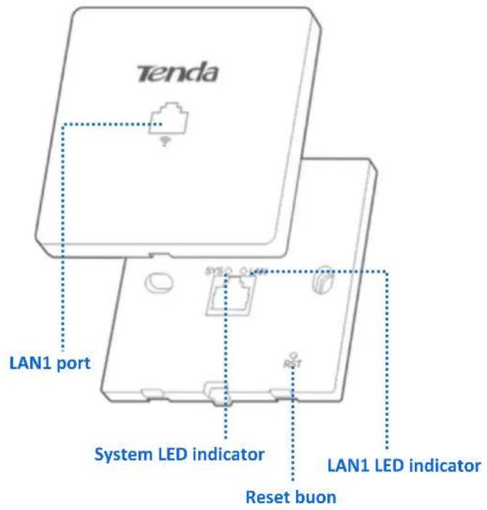
This secon describes the buon, LED indicator, ports, and label of the AP.
1.2.1 Buon, LED Indicator, and Ports
text_image
Tenda LAN1 port SYSTEM LED indicator Reset buon LAN1 LED indicator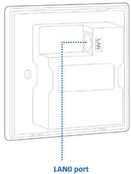
text_image
LAN LAN0 portReset Buon
It is visible aer the front cover of the AP is removed. Aer the AP is powered on, you can use a paper clip to hold down this buon for about 8 seconds to restore the factory sengs.
LED Indicator
| LED | Status | Descripon |
| SYS | Blinking green | The AP works properly. |
| O | The AP is not powered on. | |
| LAN | Solid blue | The rear (LAN0) port is connected. |
| Blinking blue | Data is being transmied over the rear (LAN0) port. | |
| O | The rear (LAN0) port is not connected. |
LAN1 Port
This port is located on the front panel of the AP and transmits data in 10/100 Mbps auto-negoaon mode. It is used to connect to a computer, a switch and so on.
LANO Port
It is located on the rear of the AP for supplying PoE power to the AP and exchanging data in 10/100 Mbps auto-negoan mode. Connect this port using an Ethernet cable to an IEEE 802.3af PoE device to supply power to the AP.
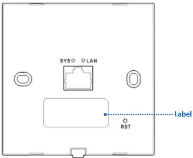
1.2.2 Label
It is visible aer the front cover of the AP is removed. The following gure shows its posion.
text_image
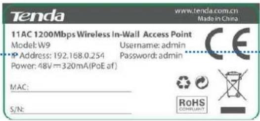
SYSO O LAN RST LabelThe label is described as follows:
(1)
text_image
Tenda www.tenda.com.cn Made in China 11AC 1200Mbps Wireless In-Wall Access Point Model: W9 Username: admin IP Address: 192.168.0.254 Password: admin Power: 48V=320mA(PoE af) MAC: S/N:(2)
(1): Default IP address of the AP. You can use this IP address to log in to the web UI of the AP.
(2): Default user name and password of the web UI of the AP.
2 Applicaon Scenarios
2.1 Large Apartment or Villa
2.1.1 Deploying the AP with a Tenda Router with the AP Controller Funconality
For a large apartment or villa, you are recommended to adopt the Tenda wireless product soluon, which includes a wired router (such as G3), a PoE switch (such as TEF1109P), and 4 to 8 W9. Deploy one W9 in each room and place the router and switch in an electronic juncon box. The following describes the procedure.
Step 1 Connect the devices.
- Connect the WAN port of the router to the ADSL or opcal modem.
- Connect a computer for conguring the AP to the LAN port of the router.
- Connect a LAN port of the router to the Uplink port of the PoE switch.
- Connect the LAN0 port of each AP to a PoE port of the switch using the in-wall CAT 5 UTP cable led into each EU-type electrical wall box used to mount the APs. See the following gure.
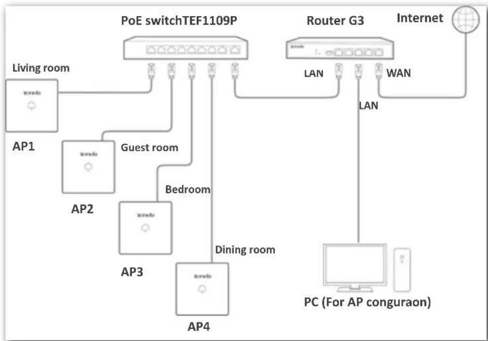
flowchart
graph TD
    A["PoE switchTEF1109P"] -->|Living room| B["AP1"]
    A -->|Guest room| C["AP2"]
    A -->|Bedroom| D["AP3"]
    A -->|Dining room| E["AP4"]
    F["Router G3"] -->|LAN| G["Internet"]
    F -->|LAN| H["PC (For AP conguraon)"]
    F -->|WAN| I["Internet"]
Step 2 Congure the AP.
- Start a web browser, enter the management IP address of the router to log in to the web UI of the router, and conjure the APs. For details about how to conjure the AP on the router web UI, refer to the user guide of the router. The user guide is available at http://www.Tenda.com.cn.
2.1.2 Deploying the AP with a Router of Another Brand
The following describes the procedure.
Step 1 Connect the devices.
-
Use an Ethernet cable to connect the computer to the PoE switch.
-
Connect one AP (such as AP1) to the PoE switch, as shown in the following topology. Change the IP address of the AP to avoid IP address conicts. Repeat this procedure to conjure the other APs.
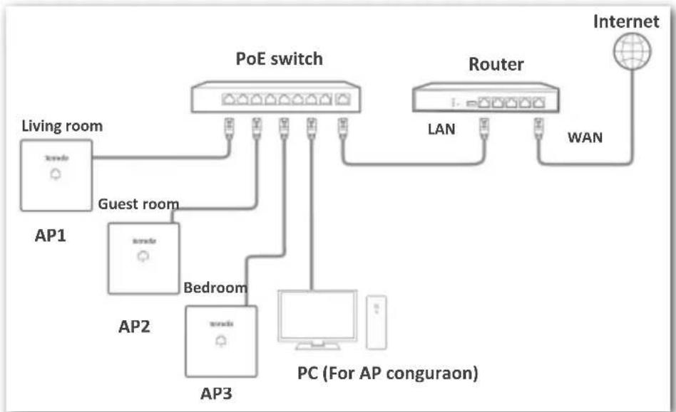
flowchart
graph TD
    A["Living room"] --> B["PoE switch"]
    C["Guest room"] --> B
    D["AP1"] --> B
    E["AP2"] --> F["Bedroom"]
    G["AP3"] --> F
    H["PC (For AP conguraon)"] --> F
    I["Router"] --> J["LAN"]
    K["Internet"] --> L["WAN"]
    B --> F
    B --> H
    B --> I
Step 2 Set the IP Address of Your Computer (Example: Windows 7).
-
Right-click the network icon in the lower-right corner of the desktop of the computer, and click Open Network and Sharing Center, Local Area Connecon, and then Properes.
-
Double-click Internet Protocol Version 4 (TCP/IPv4), select Use the following IP address, set IP address to 192.168.0.X (X: 2 - 253) and Subnet mask to 255.255.255.0, and click OK.
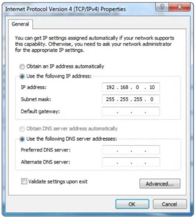
text_image
Internet Protocol Version 4 (TCP/IPv4) Properties General You can get IP settings assigned automatically if your network supports this capability. Otherwise, you need to ask your network administrator for the appropriate IP settings. Obtain an IP address automatically Use the following IP address: IP address: 192 . 168 . 0 . 10 Subnet mask: 255 . 255 . 255 . 0 Default gateway: . Obtain DNS server address automatically Use the following DNS server addresses: Preferred DNS server: . Alternate DNS server: . Validate settings upon exit Advanced... OK CancelStep 3 Log in to the Web UI of the AP.
-
Start a web browser, enter the management IP address of the AP (default: 192.168.0.254), and press Enter.
-
Enter the user name and password of the AP (default user name and password: admin) and click Login.
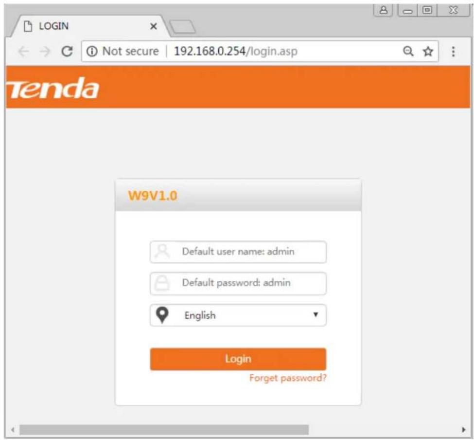
text_image
LOGIN Not secure | 192.168.0.254/login.asp Tenda W9V1.0 Default user name: admin Default password: admin English Login Forget password?Step 4 Set AP1.
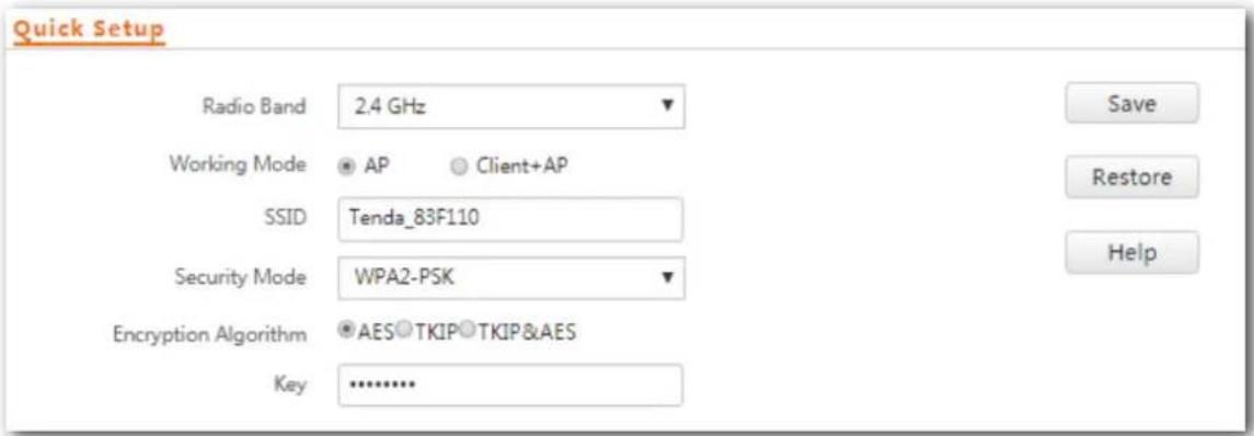
- To access the page, click Quick Setup. Select the check box of AP Mode, enter an SSID (wireless network name), select WPA2-PSK from the dropdown list box of Security Mode, select the check box of AES as the Cipher Type, enter a security key (wireless network password, such as 12345678), and click Save.
text_image
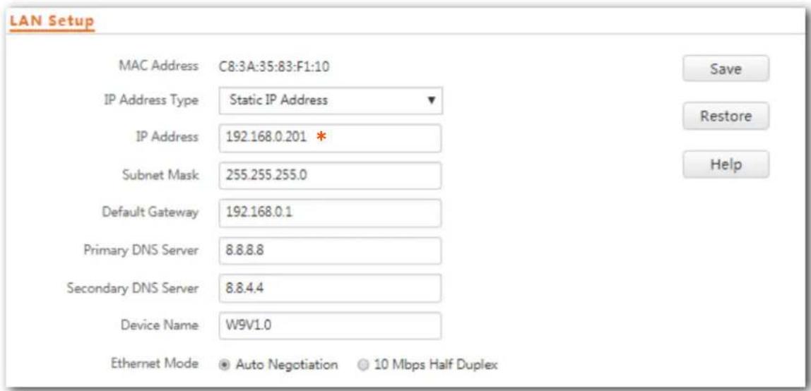
Quick Setup Radio Band 2.4 GHz Working Mode AP Client+AP SSID Tenda_83F110 Security Mode WPA2-PSK Encryption Algorithm AES TKIP TKIP&AES Key ............- Choose Network Sengs > LAN Setup, change the IP address to an unused IP address that in the same network segment as those of the later connected APs, such as 192.168.0.201, and click Save.
text_image
LAN Setup MAC Address C8:3A:35:83:F1:10 IP Address Type Static IP Address IP Address 192.168.0.201 * Subnet Mask 255.255.255.0 Default Gateway 192.168.0.1 Primary DNS Server 8.8.8.8 Secondary DNS Server 8.8.4.4 Device Name W9V1.0 Ethernet Mode Auto Negotiation 10 Mbps Half Duplex Save Restore HelpStep 5 Set the other APs. Perform step 3 and step 4 to connect the other APs to the PoE switch one by one and congure them.
For more descripon of sengs, please see contents of Chapter 4.
2.2 Hotel
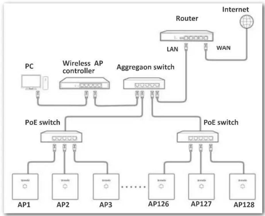
A large number of APs need to be deployed in a hotel. You can use a Tenda wireless AP controller (such as M3) to conjure and manage them centrally and eciently. The following describes the procedure.
Step 1 Connect the devices.
See the following gure.
flowchart
graph TD
    A["PC"] --> B["Wireless AP controller"]
    B --> C["Aggregaon switch"]
    C --> D["Router"]
    D --> E["Internet"]
    C --> F["PoE switch"]
    F --> G["AP1"]
    F --> H["AP2"]
    F --> I["AP3"]
    F --> J["..."]
    F --> K["AP126"]
    F --> L["AP127"]
    F --> M["AP128"]
    D --> N["LAN"]
    D --> O["WAN"]
Step 2 Congure the APs.
Log in to the web UI of the AP controller on the computer connected to the AP controller. For details about how to congregate the AP on the web UI of the AP controller, visit http://www.Tenda.com.cn to download the user guide.
The following chapters describe how to congregate the AP on the web UI of the AP.
3 Login
3.1 Logging in to the Web UI of the AP
You can log in to the web UI of the AP using a web browser. The procedure is as follows:
Step 1 Use an Ethernet cable to connect the management computer to the AP or the switch connected to the AP.
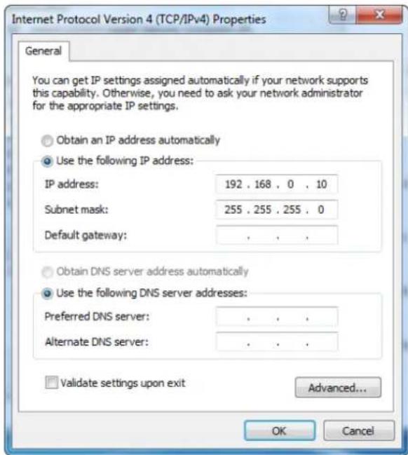
Step 2 Set IP address of your local area conneccon to 192.168.0.X (X: 2 - 253) and Subnet mask to 255.255.255.0.
text_image
Internet Protocol Version 4 (TCP/IPv4) Properties General You can get IP settings assigned automatically if your network supports this capability. Otherwise, you need to ask your network administrator for the appropriate IP settings. Obtain an IP address automatically Use the following IP address: IP address: 192 . 168 . 0 . 10 Subnet mask: 255 . 255 . 255 . 0 Default gateway: . Obtain DNS server address automatically Use the following DNS server addresses: Preferred DNS server: . Alternate DNS server: . Validate settings upon exit Advanced... OK CancelStep 3 Start a web browser on the computer, enter the management IP address of the AP (default: 192.168.0.254) in the address bar, and press Enter.
Step 4 Enter the user name and password of the AP (default user name and password: admin/admin) and click Login.
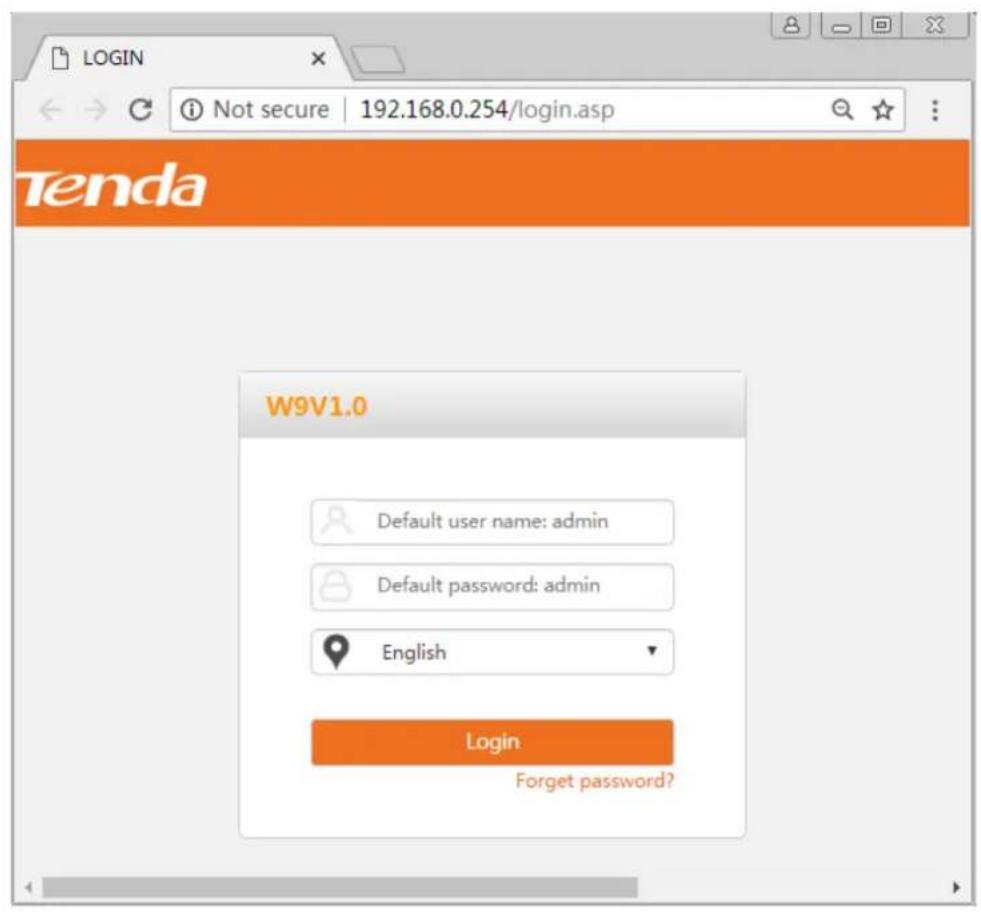
text_image
LOGIN Not secure | 192.168.0.254/login.asp Tenda W9V1.0 Default user name: admin Default password: admin English Login Forget password?
If the login page is not displayed, refer to Q2 in FAQ.
---End
You can now start conguring the AP.
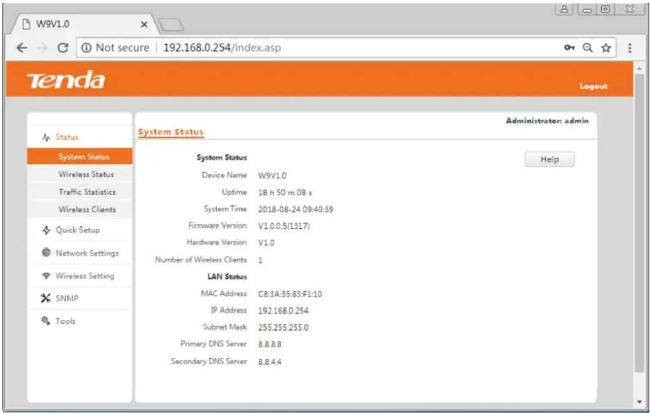
text_image
W9V1.0 Not secure | 192.168.0.254/index.asp Tenda Logout Status System Status Wireless Status Traffic Statistics Wireless Clients Quick Setup Network Settings Wireless Setting SNMP Tools System Status Device Name W9V1.0 Uptime 18 h 50 m 08 s System Time 2018-08-24 09:40:59 Firmware Version V1.0.0.5(1317) Hardware Version V1.0 Number of Wireless Clients 1 LAN Status MAC Address C8:3A:35:83:F1:10 IP Address 192.168.0.254 Subnet Mask 255.255.255.0 Primary DNS Server 8.8.8.8 Secondary DNS Server 8.8.4.4 Administrator: admin Help3.2 Logging out of the Web UI of the AP
If you log in to the web UI of the AP and perform no operaon within the login meout interval, the AP logs you out. When you close the web browser, the system logs you out as well. You can log out by clicking Logout in the upper-right corner.
3.3 Web UI Layout
The web UI of the AP is composed of four parts, including the 1-level navigaon tree, 2-level navigaon tree, tab page area, and conguraon area. See the following gure.
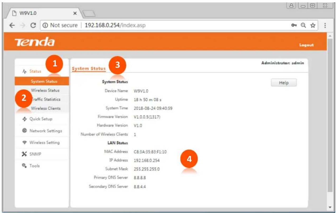
text_image
W9V1.0 ① Not secure | 192.168.0.254/index.asp Tenda Logout 1 System Status 3 Administrator: admin Status System Status 2 Wireless Status Traffic Statistics Wireless Clients Quick Setup Network Settings Wireless Setting SNMP Tools System Status Device Name W9V1.0 Uptime 18 h 50 m 08 s System Time 2018-08-24 09:40:59 Firmware Version V1.0.0.5(1317) Hardware Version V1.0 Number of Wireless Clients 1 LAN Status MAC Address C8:3A:35:83:F1:10 IP Address 192.168.0.254 Subnet Mask 255.255.255.0 Primary DNS Server 8.8.8.8 Secondary DNS Server 8.8.4.4 4 Help
The funcons and parameters dimmed on the web UI indicates that they are not supported by the AP or cannot be changed in the current conguraon.
| No. | Name | Descripon |
| 1 | 1-level navigaon bar | The navigaon bars and tab pages display the funcon menu of the AP. When you select a funcon in navigaon bar, the conguraon of the funcon appears in the conguraon area. |
| 2 | 2-level navigaon bar | |
| 3 | Tab page area | |
| 4 | Conguraon area | It enables you to view and modify conguraon. |
3.4 Common Buons
The following table describes the common buons available on the web UI of the AP.
| Buon | Descripon |
| Refresh | It is used to refresh the current page. |
| Save | It is used to save the conguraon on the current page and enable the conguraon to take eect. |
| Restore | It is used to change the current conguraon on the current page back to the original conguraon. |
| Help | It is used to view help informaon corresponding to the sengs on the current page. |
4 Quick Setup
4.1 Overview
This module enables you to quickly congregate the AP so that wireless devices such as smart phones and tablets can access the internet through the wireless network of the AP.
This AP can work in AP mode or Client+AP mode.
AP Mode
By default, the AP works in this mode. In this mode, the AP connects to the internet using an Ethernet cable and converts wired signals into wireless signals to provide wireless network coverage. See the following topology.
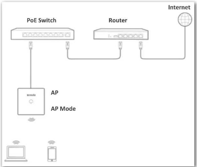
flowchart
graph TD
    A["PoE Switch"] --> B["AP Mode"]
    C["Router"] --> B
    B --> D["Internet"]
    E["Mobile Device"] --> F["AP Mode"]
    G["Smartphone"] --> H["AP Mode"]
Client+AP Mode
In this mode, the AP is wirelessly bridged to an upstream device (such as a wireless router or AP) to extend the wireless network coverage of the upstream device. See the following topology.
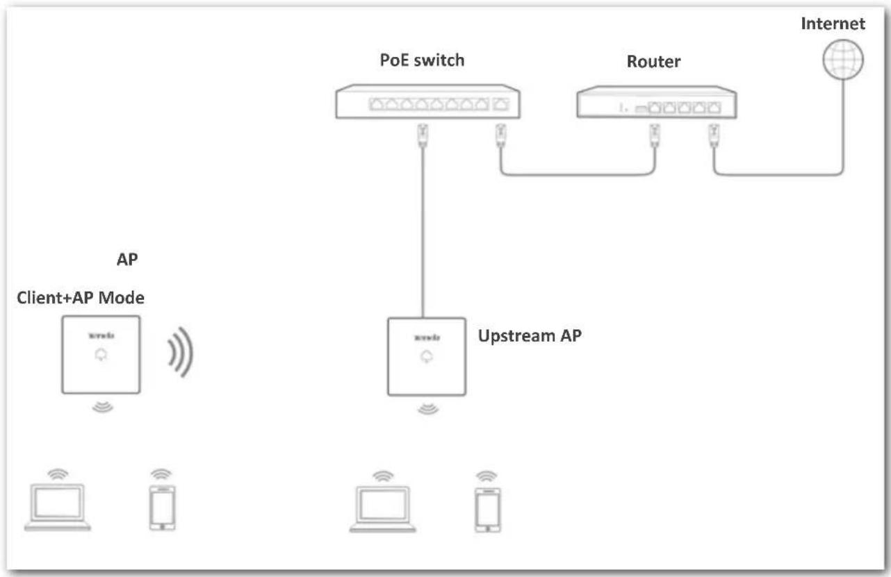
flowchart
graph TD
    A["Client+AP Mode"] -->|AP| B["Upstream AP"]
    B --> C["PoE switch"]
    C --> D["Router"]
    D --> E["Internet"]
    style A fill:#f9f,stroke:#333
    style B fill:#ccf,stroke:#333
    style C fill:#cfc,stroke:#333
    style D fill:#fcc,stroke:#333
    style E fill:#cff,stroke:#333
4.2 Quick Setup
4.2.1 AP Mode

Before conguraon, ensure that the upstream device has been connected to the internet.
Step 1 Choose Quick Setup.
Step 2 Select a radio band from the drop-down list box to be congured, which is 2.4 GHz in this example.
Step 3 Keep the default conguraon of working mode.
Step 4 (Oponal) Change the value of SSID, which indicates the primary SSID of the AP, to your wireless network name.
Step 5 Select a security mode from the Security Mode drop-down list box and set the corresponding parameters. (You are recommended to set Security Mode to WPA2-PSK and Encrypon Algorithm to AES.)
Step 6 Click Save.
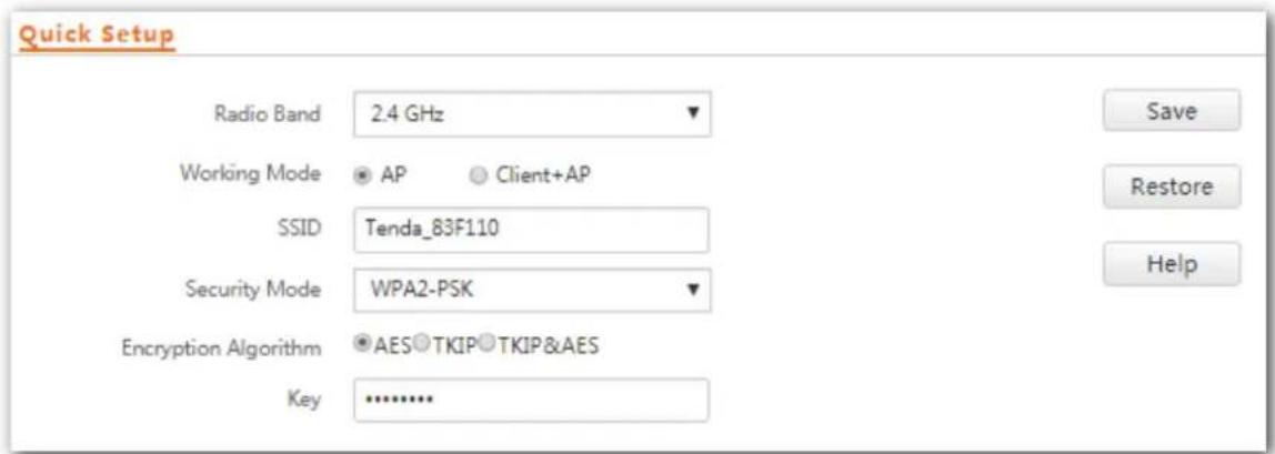
text_image
Quick Setup Radio Band 2.4 GHz Working Mode AP Client+AP SSID Tenda_83F110 Security Mode WPA2-PSK Encryption Algorithm AES TKIP TKIP&AES Key ............Step 7 To congregate the WIFI network of another radio band, select the radio band, and repeat steps 3-6. ---End
Parameter descripon
| Parameter | Descripon |
| Radio Band | It species the radio band of the WiFi network to be congured. |
| Working Mode | It species the working mode of the AP, including AP mode and Client+AP mode. |
| SSID | It species the primary SSID (wireless network name) of the AP. |
| Security Mode | It species the security mode of the wireless network of the AP. Opons include: None, WEP, WPA-PSK, WPA2-PSK, Mixed WPA/WPA2-PSK, WPA, and WPA2.Clicking the hyperlink navigates you to the elaborated descripon of the corresponding security mode. |
| Encrypon Algorithm | It species the WPA encrypon algorithm of the repeated WiFi network. Aer you select the upstream WiFi network from the scanned wireless network list, this parameter will be populated automacally. |
| Key | Manually enter the WiFi password of the repeated WiFi network. |
Aer the conguraon, you can select the SSID on your wireless devices such as smart phones and enter your wireless network password to connect to the wireless network of the AP and access the internet through the AP.
4.2.2 Client+AP Mode

Before conguraon, ensure that the upstream AP has been connected to the internet.
For two bands bridging scenario, please ensure that you choose the same upstream AP for both the 2.4 GHz and 5 GHz WiFi networks.
Step 1 Choose Quick Setup.
Step 2 Select the radio band from the drop-down list box to be congured, which is 2.4 GHz in this example.
Step 3 Set Working Mode to Client+AP.
Step 4 Click Scan.
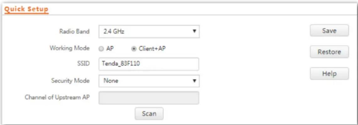
text_image
Quick Setup Radio Band 2.4 GHz Working Mode AP Client+AP SSID Tenda_83F110 Security Mode None Channel of Upstream AP Scan Save Restore HelpStep 5 Select the wireless network to be extended from the wireless network list that appears.
NOTE
- If no wireless network is found, choose Wireless Sengs > Radio Setngs, ensure that Enable Wireless is selected, and try scanning wireless network again.
- After a wireless network to be extended is selected, the SSID, security mode, and channel of the wireless network are populated automatically. The Key (if any) should be entered manually.
Step 6 Click Disable Scan.
| Select | SSID | MAC Address | Network Mode | Channel Bandwidth | Channel | Extension Channel | Security Mode | Signal Strength |
| ○ | Tenda_843F00 | c8:3a:35:84:3f:01 | bgn | 20MHz | 7 | none | none | -14dBm |
| ○ | Tenda_366FC0 | c8:3a:35:36:6f:c1 | bgn | 20MHz | 8 | none | wpa&wpa2/aes | -34dBm |
Step 7 If the wireless network of the upstream device is encrypted, set Key to the wireless network password of the device.
Step 8 Click Save.
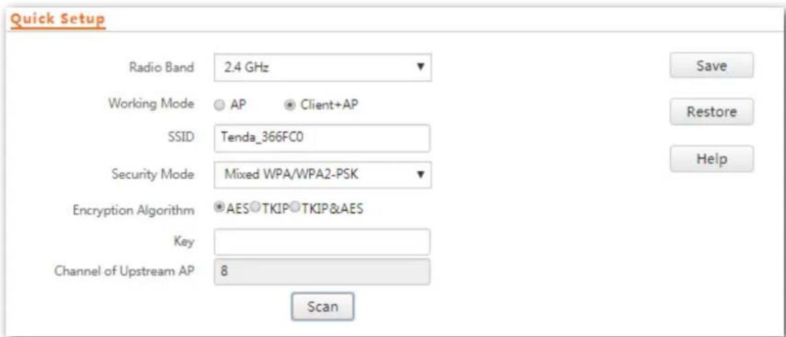
text_image
Quick Setup Radio Band 2.4 GHz Working Mode AP Client+AP SSID Tenda_366FC0 Security Mode Mixed WPA/WPA2-PSK Encryption Algorithm AES TKIP TKIP&AES Key Channel of Upstream AP 8 Scan Save Restore HelpStep 9 To extend the WiFi network at 5 GHz radio band, select the radio band, and repeat steps 3-8.
---End
Aer the conguraon, you can select the SSID (click Status > Wireless Status to view the SSID of this AP) on your wireless devices such as smart phones and enter your wireless network password to connect to the wireless network of the AP and access the internet through the AP.
If you do not know the SSID of the AP, go to the Wireless Setngs > SSID Sengs page.
Parameter Descripon
| Parameter | Descripon |
| Radio Band | It species the radio band of the WiFi network to be congured. |
| Working Mode | It species the working mode of the AP, including AP mode and Client+AP mode.AP mode: In this mode, wireless clients can connect to this device, but this device cannot connect to peers.Client+AP mode: In this mode, this device is bridged wirelessly to an upstream device and provides the wireless access service to clients. |
| SSID | It species the WiFi network name (SSID) of the WiFi network to be repeated. Aer you select the upstream WiFi network from the scanned wireless network list, this parameter will be populated automacally. |
| Security Mode | It species the security mode of which the upstream WiFi network adopted. Aer you select the upstream WiFi network from the scanned wireless network list, this parameter will be populated automacally.The AP can repeat WiFi network encrypted with None or WEP (Open or Shared), WPA-PSK, WPA2-PSK and Mixed WPA/WPA2-PSK.Clicking the hyperlink navigates you to the elaborated descripon of the corresponding security mode.NOTEThe AP can scan the WiFi network with WPA (WPA2) Enterprise encrypon, but cannot identify its security mode. |
| Authencaon Type | Manually select the authencaon type of the upstream device if the security mode of the upstream device is WEP. |
| Default Key | Manually choose the default key number of the upstream device if the security mode of the upstream device is WEP. |
| Key 1/2/3/4 | WiFi password of the upstream device if the security mode of the upstream device is WEP. |
| Encrypon Algorithm | It species the WPA encrypon algorithm of the repeated WiFi network. Aer you select the upstream WiFi network from the scanned wireless network list, this parameter will be populated automacally. |
| Key | Manually enter the WiFi password of the upstream device if the security mode of the upstream device is WPA. |
| Channel of Upstream AP | It species the channel of the upstream AP. Aer you select the upstream WiFi network from the scanned wireless network list, this parameter will be populated automacally. |
5 Status
This module allows you to view system status, wireless status, trafc stascs and wireless clients.
5.1 System Status
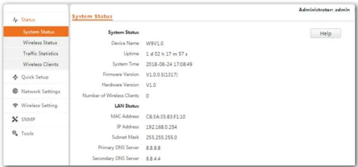
To access the page, choose Status > System Status.
The page displays the system and LAN port status of the AP.
text_image
System Status Administrator: admin System Status Device Name W9V1.0 Uptime 1 d 02 h 17 m 57 s System Time 2018-08-24 17:08:49 Firmware Version V1.0.0.5(1317) Hardware Version V1.0 Number of Wireless Clients 0 LAN Status MAC Address C8:3A:35:83:F1:10 IP Address 192.168.0.254 Subnet Mask 255.255.255.0 Primary DNS Server 8.8.8.8 Secondary DNS Server 8.8.4.4 Wireless Status Traffic Statistics Wireless Clients Quick Setup Network Settings Wireless Setting SNMP ToolsParameter descripon
| Parameter | Descripon |
| Device Name | It species the name of the AP.A unique AP name helps quickly identify the AP. You can change the AP name on the Network Sengs > LAN Setup page. |
| Upme | It species the me that has elapsed since the AP was started last me. |
| System Time | It species the current system me of the AP. |
| Number of Wireless Clients | It species the number of wireless clients currently connected to the AP. |
| Firmware Version | It species the rmware version number of the AP. |
| Hardware Version | It species the hardware version number of the AP. |
| MAC Address | It species the physical address of the LAN port of the AP. If you connect the AP to other devices using Ethernet cables, the AP uses this MAC address to communicate with those devices. |
| IP Address | It species the IP address of the AP.The web UI of the AP is accessible at this IP address. You can change the IP address on the Network Sengs > LAN Setup page. |
| Subnet Mask | It species the subnet mask of the IP address of the AP. |
| Primary DNS Server | It species the primary DNS server of the AP. |
| Secondary DNS Server | It species the secondary DNS server of the AP. |
5.2 Wireless Status
The access the page, choose Status > Wireless Status.
This page displays general radio status and SSID status of the AP. By default, the page displays the informaon of 2.4 GHz wireless status. To view the wireless status of 5 GHz, click 5 GHz Wireless Status.
2.4 GHz Wireless Status 5 GHz Wireless Status
| Radio Status | |
| Radio (On/Off) | On |
| Network Mode | 11b/g/n |
| Channel | 7 |
Help
| SSID Status | |||
| SSID | MAC Address | Working Status | Security Mode |
| Tenda_83F110 | C8:3A:35:83:F1:11 | Enabled | None |
| Tenda_83F111 | C8:3A:35:83:F1:12 | Disabled | None |
| Tenda_83F112 | C8:3A:35:83:F1:13 | Disabled | None |
| Tenda_83F113 | C8:3A:35:83:F1:14 | Disabled | None |
| Tenda_83F114 | C8:3A:35:83:F1:15 | Disabled | None |
| Tenda_83F115 | C8:3A:35:83:F1:16 | Disabled | None |
| Tenda_83F116 | C8:3A:35:83:F1:17 | Disabled | None |
| Tenda_83F117 | C8:3A:35:83:F1:18 | Disabled | None |
Parameter descripon
| Parameter | Descripon | |
| Radio Status | Radio (On/O) | It species whether the wireless funcon of the AP is enabled. |
| Network Mode | It species the current network mode of the AP. | |
| Channel | It species the current working channel of the AP. | |
| SSID Status | SSID | It species the names of all the wireless networks of the AP. |
| MAC Address | It species the physical addresses corresponding to the SSIDs of the AP. | |
| Working Status | It species whether the wireless networks corresponding to the SSIDs of the AP are enabled. | |
| Security Mode | It species the security modes of the wireless networks corresponding to the SSIDs of the AP. |
5.3 Trac Stascs
To access the page, choose Status > Trac Stascs.
This page displays the stascs about historical packets of the wireless networks of the AP.
By default the page displays the trac stascs informaon of 2.4 GHz. To view informaon about 5 GHz, click 5 GHz Trac Stascs. To view the latest stascs, click Refresh.
2.4 GHz Traffic Statistics 5 GHz Traffic Statistics
| SSID | Received Traffic | Received Packets | Transmitted Traffic | Transmitted Packets |
| Tenda_83F110 | 2031.21MB | 8756335 | 10.59MB | 89907 |
| Tenda_83F111 | 0.00MB | 0 | 0.00MB | 0 |
| Tenda_83F112 | 0.00MB | 0 | 0.00MB | 0 |
| Tenda_83F113 | 0.00MB | 0 | 0.00MB | 0 |
| Tenda_83F114 | 0.00MB | 0 | 0.00MB | 0 |
| Tenda_83F115 | 0.00MB | 0 | 0.00MB | 0 |
| Tenda_83F116 | 0.00MB | 0 | 0.00MB | 0 |
| Tenda_83F117 | 0.00MB | 0 | 0.00MB | 0 |
5.4 Wireless Clients
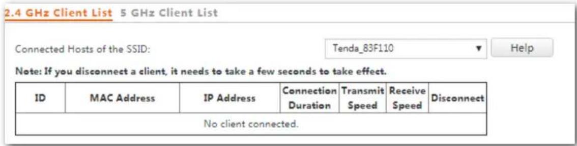
To access the page, choose Status > Wireless Clients.
This page displays informaon about the wireless clients connected to the wireless networks corresponding to the SSIDs of the AP.
text_image
2.4 GHz Client List 5 GHz Client List Connected Hosts of the SSID: Tenda_83F110 Note: If you disconnect a client, it needs to take a few seconds to take effect. ID MAC Address IP Address Connection Duration Transmit Speed Receive Speed Disconnect No client connected.By default, the page displays informaon about the wireless clients connected to the 2.4 GHz wireless network corresponding to the primary SSID of the AP. To view informaon about the wireless clients connected to the 5 GHz wireless network corresponding to the other SSID, click the 5 GHz Client List tab, and select the SSID from the drop-down list box in the upper-right corner.
Parameter descripon
| Parameter | Descripon |
| MAC Address | It species the MAC address of the wireless client. |
| IP Address | It species the IP address of the wireless client. |
| Connecon Duraon | It species the online me of the wireless client. |
| Transmit Speed | It species the current transmit speed of the wireless client. |
| Receive Speed | It species the current receive speed of the wireless client. |
| Disconnect | Clicking ✗ disconnects the corresponding client. To view the disconnected client, choose Wireless Seng > Access Control. |
6 Network Sengs
6.1 LAN Setup
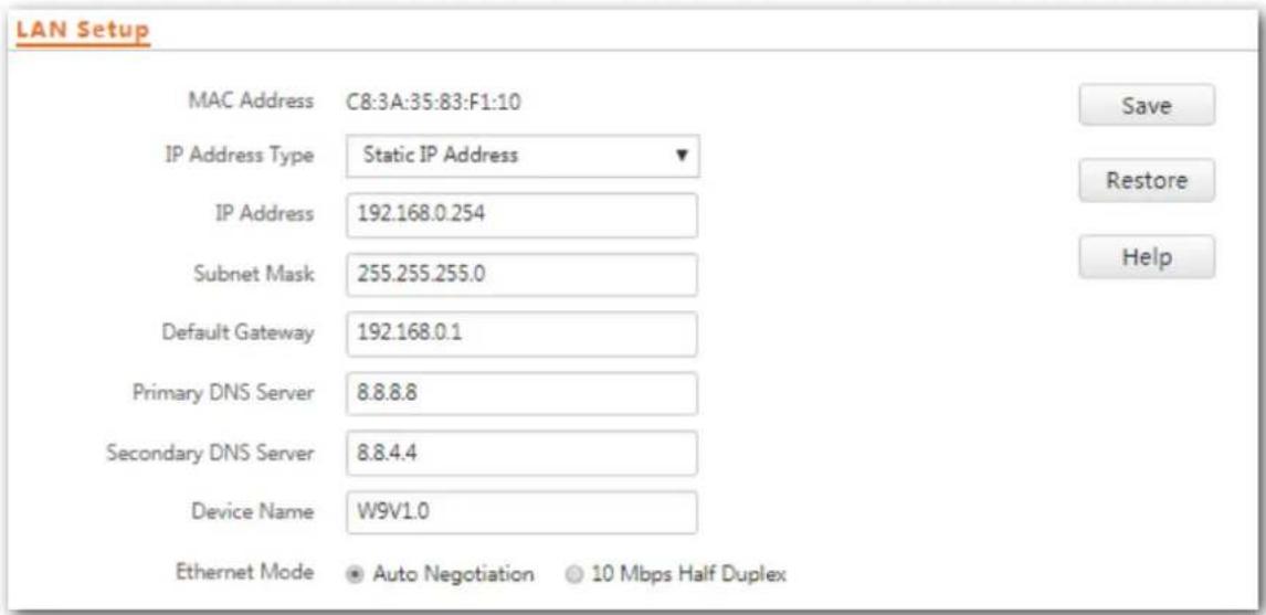
To access the page, choose Network Setngs > LAN Setup.
This page enables you to view the MAC address of the LAN port of the AP and set the name, Ethernet Mode, IP obtaining method, and other related parameters of the AP.
text_image
LAN Setup MAC Address C8:3A:35:83:F1:10 IP Address Type Static IP Address IP Address 192.168.0.254 Subnet Mask 255.255.255.0 Default Gateway 192.168.0.1 Primary DNS Server 8.8.8.8 Secondary DNS Server 8.8.4.4 Device Name W9V1.0 Ethernet Mode Auto Negotiation 10 Mbps Half Duplex Save Restore HelpParameter descripon
| Parameter | Descripon |
| MAC Address | It species the MAC address of the LAN port of the AP.The default primary SSID of the AP is Tenda_XXXXXX, where XXXXXX indicates the last 6 characters of this MAC address. |
| IP Address Type | It species the IP address obtaining mode of the AP. The default opon is Static IP Address.Static IP Address: It indicates that the IP address, subnet mask, gateway, and DNS server informaon of the AP is set manually.DHCP: It indicates that the IP address, subnet mask, gateway, and DNS server informaon of the AP is obtained from a DHCP server on your LAN. If Address Mode is set to DHCP, you can log in to the web UI of the AP only with the IP address assigned to the AP by the DHCP server. The IP address is specied on the client list of the DHCserver. If Address Mode is set to DHCP, you can log in to the web UI of the AP only with the IP address assigned to the AP by the DHCP server. The IP address is specied on the client list of the DHCserver. |
| IP Address | It species the IP address of the AP. The web UI of the AP is accessible at this IP address. The default IP address is 192.168.0.254.Generally, ensure that this IP address is in the same network segment as the LAN IP address of your LAN router connected to the internet, so that the AP can access the internet. |
| Subnet Mask | It species the subnet mask of the IP address of the AP. The default subnet mask is 255.255.255.0. |
| Gateway | It species the gateway IP address of the AP.Generally, set the gateway IP address to the LAN IP address of your LAN router connected to the internet, so that the AP can access the internet. |
| Primary DNS Server | It species the primary DNS server of the AP.If your LAN router connected to the internet provides the DNS proxy funcon, this IP address can be the LAN IP address of the router. Otherwise, enter a correct DNS server IP address. |
| Secondary DNS Server | It species the IP address of the secondary DNS server of the AP. This parameter is oponal.If a DNS server IP address in addition to the IP address of the primary DNS server is available, enter the additional IP address in this eld. |
| Device Name | It species the name of the AP. By default, the name is the model of the AP, such as W9V1.0.You are recommended to change the name of the AP to indicate the locaon of the AP (such as Bedroom), so that you can easily identify the AP when managing many APs. |
| Ethernet Mode | It species the Ethernet mode of LAN0 of this AP.Auto Negoaon: This mode features a high transmission rate but short transmission distance. Generally, this mode is recommended.10 Mbps Half Duplex: This mode features a long transmission distance but relatively low transmission rate (usually 10 Mbps).This mode is recommended only if the Ethernet cable that connects the LAN0 port of the AP to a peer device exceeds 100 meters. In this case, the connected LAN port of the peer device must work in auto-negoaon mode. Otherwise, the LAN0 port of the AP may not be able to properly transmit or receive data. |
6.1.1 Modifying the LAN IP Address of the AP
Manually Seng the IP Address
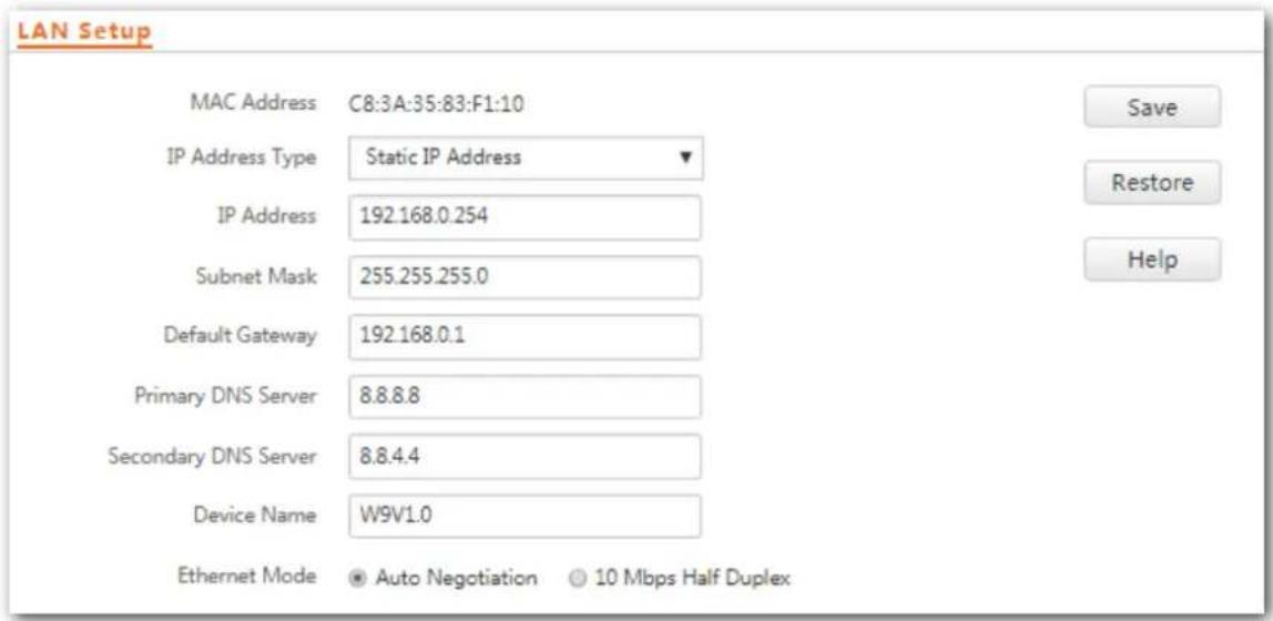
In this mode, you must manually set the IP address, subnet mask, gateway IP address, and DNS server IP addresses of the AP. Therefore, this mode is recommended if you need to deploy only a few APs.
Conguraon procedure:
Step 1 Choose Network Setngs > LAN Setup.
Step 2 Set IP Address Type to Stac IP Address.
Step 3 Set IP Address, Subnet Mask, Default Gateway, and Primary DNS Server. If another DNS server is available, set Secondary DNS Server to the IP address of the additional DNS server.
Step 4 Click Save.
text_image
LAN Setup MAC Address C8:3A:35:83:F1:10 IP Address Type Static IP Address IP Address 192.168.0.254 Subnet Mask 255.255.255.0 Default Gateway 192.168.0.1 Primary DNS Server 8.8.8.8 Secondary DNS Server 8.8.4.4 Device Name W9V1.0 Ethernet Mode Auto Negotiation 10 Mbps Half Duplex Save Restore HelpStep 5 Click OK.
192.168.0.254 says
If you change this IP address, you can log in again only with the new IP address.

---End
The following page is displayed. To connue to congure the AP, please do as follows:
- If the new and original IP addresses belong to the same network segment, click Back to log in to the web UI of AP again.
- Otherwise, assign your computer an IP address that belongs to the same network segment as the new IP address of the AP before login.
Please wait about 10 seconds for saving the new IP address.
Back
Automacally Obtaining an IP Address
This mode enables the AP to automacally obtain an IP address, a subnet mask, a gateway IP address, DNS server IP addresses from a DHCP server on your LAN. If a large number of APs are deployed, you can adopt this mode to avoid IP address conicts and eecvely reduce your workload.
Conguraon procedure:
Step 1 Choose Network Setngs > LAN Setup.
Step 2 Set Address Mode to DHCP.
Step 3 Click Save.
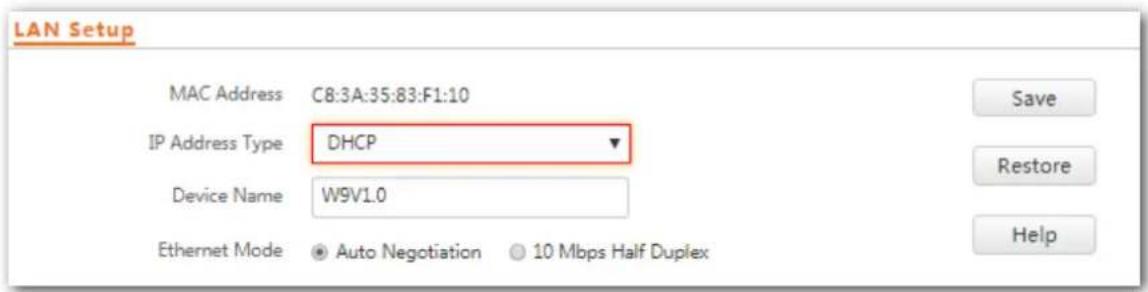
text_image
LAN Setup MAC Address C8:3A:35:83:F1:10 IP Address Type DHCP Device Name W9V1.0 Ethernet Mode Auto Negotiation 10 Mbps Half Duplex Save Restore Help---End
Aer the conguraon, if you want to log in to the web UI of the AP again, check the client list of the DHCP server for the IP address assigned to the AP, ensure that the IP address of the management computer and the IP address of the AP belong to the same network segment, and access the IP address of the AP.
6.2 DHCP Server
6.2.1 Overview
The AP provides a DHCP server funcon to assign IP addresses to clients on the LAN. By default, the DHCP server funcon is disabled.

If the new and original IP addresses of the LAN port belong to dierent network segment, the system changes the IP address pool of the DHCP server funcon of the AP so that the IP address pool and the new IP address of the LAN port belong to the same network segment.
6.2.2 Conguring the DHCP Server
Step 1 Choose Network Setngs > DHCP Server.
Step 2 Set the parameters. Generally, you need to set only DHCP Server, Gateway Address, and Primary DNS Server.
Step 3 Click Save.
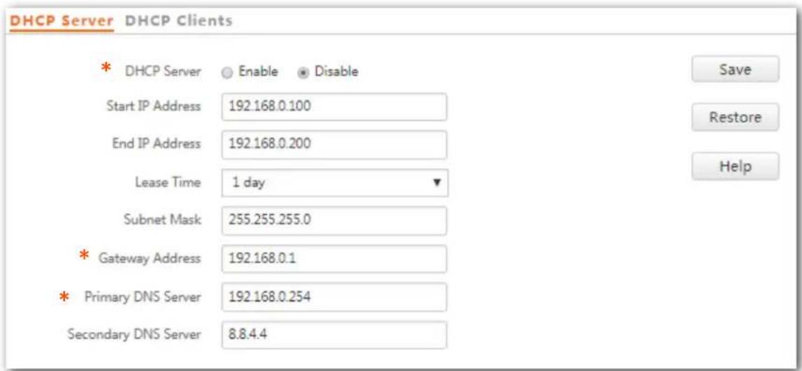
text_image
DHCP Server DHCP Clients * DHCP Server ○ Enable ● Disable Start IP Address 192.168.0.100 End IP Address 192.168.0.200 Lease Time 1 day ▼ Subnet Mask 255.255.255.0 * Gateway Address 192.168.0.1 * Primary DNS Server 192.168.0.254 Secondary DNS Server 8.8.4.4 Save Restore Help--End
Parameter descripon
| Parameter | Descripon |
| DHCP Server | It species whether to enable the DHCP server funcon of the AP. By default, it is disabled. |
| Start IP Address | It species the start IP address of the IP address pool of the DHCP server. The default value is 192.168.0.100. |
| End IP Address | It species the end IP address of the IP address pool of the DHCP server. The default value is 192.168.0.200.TIPThe start and end IP addresses must belong to the same network segment as the IP address of the LAN port of the AP. |
| Lease Time | It species the validity period of an IP address assigned by the DHCP server to a client.When half of the lease me has elapsed, the client sends a DHCP Request to the DHCP server to renew the lease me. If the request succeeds, the lease me is extended according to the request. Otherwise, the client sends the request again when 7/8 of the lease me has elapsed. If the request succeeds, the lease me is extended according to the request. Otherwise, the client must request an IP address from the DHCP server aer the lease me expires.It is recommended that you retain the default value 1 day. |
| Subnet Mask | It species the subnet mask assigned by the DHCP server to clients. The default value is 255.255.255.0. |
| Gateway Address | It species the default IP address gateway assigned by the DHCP server to clients. Generally, it is the IP address of the LAN port of a router on the LAN. The default value is 192.168.0.254.A client can access a server or host not in the local network segment only through a gateway. |
| Primary DNS Server | It species the primary DNS server IP address assigned by the DHCP server to clients. The default value is 192.168.0.254.TIPTo enable clients to access the internet, set this parameter to a correct DNS server IP address or DNS proxy IP address. |
| Secondary DNS Server | It species the secondary DNS server IP address assigned by the DHCP server to clients. This parameter is oponal. |

If another DHCP server is available on your LAN, ensure that the IP address pool of the AP does not overlap the IP address pool of that DHCP server. Otherwise, IP address conicts may occur.
6.2.3 Viewing the DHCP Client List
If the AP funcons as a DHCP server, you can view the DHCP client list to understand the details about the clients that obtain IP addresses from the DHCP server. The details include host names, IP addresses, MAC addresses, and lease mes.
To access the page, choose Network Setngs > DHCP Server and click DHCP Client tab.
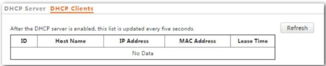
text_image
DHCP Server DHCP Clients After the DHCP server is enabled, this list is updated every five seconds. Refresh ID Host Name IP Address MAC Address Lease Time No DataTo view the latest DHCP client list, click Refresh.
7 Wireless Sengs
7.1 Basic Sengs
7.1.1 Overview
This module enables you to set SSID-related parameters of the AP.
Broadcast SSID
When the AP broadcasts an SSID, nearby wireless clients can detect the SSID. When this parameter is set to Disable, the AP does not broadcast the SSID and nearby wireless clients cannot detect the SSID. In this case, you need to enter the SSID manually on your wireless client if you want to connect to the wireless network corresponding to the SSID. It enhances the security of the wireless network.
It is worth nong that aer Broadcast SSID is set to Disable, a hacker can sll connect to the corresponding wireless network if he/she manages to obtain the SSID by other means.
Isolate Client
This parameter implements a funcon similar to the VLAN funcon for wired networks. It isolates the wireless clients connected to the same wireless network corresponding to an SSID, so that the wireless clients can access only the wired network connected to the AP. Applying this funcon to hotspot setup at public places such as hotels and airports helps increase network security.
WMF
The number of wireless clients keeps increasing currently, but wired and wireless bandwidth resources are limited. Therefore, the mulcast technology, which enables single-point data transmission and mul-point data reception, has been widely used in networks to effectively reduce bandwidth requirements and prevent network congestion.
Nevertheless, if a large number of clients are connected to a wireless interface of a wireless network and mulcast data is intended for only one of the clients, the data is sll sent to all the clients, which unnecessarily increases wireless resource usage and may lead to wireless channel congeson. In addition, mulcast stream forwarding over an 802.11 network is not secure.
The WMF funcon of the AP converts mulcast trac into unicast trac and forwards the trac to the mulcast trac desnaon in the wireless network. This helps save wireless resources, ensure reliable transmission, and reduce delays.
Max. Number of Clients
This parameter species the maximum number of clients that can connect to the wireless network corresponding to an SSID. If the number is reached, the wireless network rejects new conncon requests from clients. This limit helps balance load among APs.
Security Mode
A wireless network uses radio, which is open to the public, as its data transmission medium. If the wireless network is not protected by necessary measures, any client can connect to the network to use the resources of the network or access unprotected data over the network. To ensure communicaon security, transmission links of wireless networks must be encrypted for protecon.
The AP supports various security modes for network encrypon, including None, WEP, WPA-PSK, WPA2-PSK, Mixed WPA/WPA2-PSK, WPA, and WPA2.
None
It indicates that any wireless client can connect to the wireless network. This opon is not recommended because it aects network security.
WEP
It uses a stac key to encrypt all exchanged data, and ensures that a wireless LAN has the same level of security as a wired LAN. Data encrypted based on WEP can be easily cracked. In addition, WEP supports a maximum wireless network throughput of only 54 Mbps. Therefore, this security mode is not recommended.
WPA-PSK, WPA2-PSK, and Mixed WPA/WPA2-PSK
They belong to pre-shared key or personal key modes, where Mixed WPA/WPA2-PSK supports both WPA-PSK and WPA2-PSK.
WPA-PSK, WPA2-PSK, and Mixed WPA/WPA2-PSK adopt a pre-shared key for authencaon, while the AP generates another key for data encrypon. This prevents the vulnerability caused by stac WEP keys, and makes the three security modes suitable for ensuring security of home wireless networks. Nevertheless, because the initial pre-shared key for authencaon is manually set and all clients use the same key to connect to the same AP, the key may be disclosed unexpectedly. This makes the security modes not suitable for scenarios where high security is required.
WPA and WPA2
To address the key management weakness of WPA-PSK and WPA2-PSK, the WiFi Alliance puts forward WPA and WPA2, which use 802.1x to authenticate clients and generate data encrypon-oriented root keys. WPA and WPA2 use the root keys to replace the pre-shared keys that set manually, but adopt the same encrypon process as WPA-PSK and WPA2-PSK.
WPA and WPA2 uses 802.1x to authenticate clients and the login informaon of a client is managed by the client. This eecvely reduces the probability of informaon leakage. In addition, each me a client connects to an AP that adopts the WPA or WPA2 security mode, the RADIUS server generates a data encrypon key and assigns it to the client. This makes it dicult for aackers to obtain the key. These features of WPA and WPA2 help significantly increase network security, making WPA and WPA2 the preferred security modes of wireless networks that require high security.
7.1.2 Modifying SSID Sengs
To change the related sengs of an SSID, perform the following procedure:
Step 1 Choose Wireless Setng> SSID Sengs.
Step 2 Click the tab to choose the radio band to be set.
Step 3 Change the parameters as required. Generally, you only need to change the Enable, SSID, and Security Mode sengs.
Step 4 Click Save.
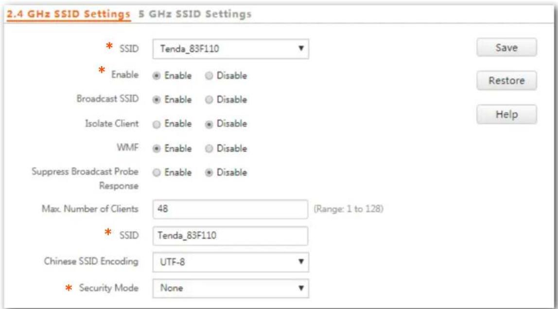
text_image
2.4 GHz SSID Settings 5 GHz SSID Settings * SSID Tenda_83F110 * Enable Enable Disable Broadcast SSID Enable Disable Isolate Client Enable Disable WMF Enable Disable Suppress Broadcast Probe Enable Disable Response Max. Number of Clients 48 (Range: 1 to 128) * SSID Tenda_83F110 Chinese SSID Encoding UTF-8 * Security Mode None---End
Parameter descripon
| Parameter | Descripon |
| SSID | It species the SSID to be congured.The AP supports 8 SSIDs for the 2.4 GHz and 4 SSIDs for the 5 GHz, and the rst SSID displayed is the primary SSID. |
| Enable | It species whether to enable the selected SSID.By default, the primary SSID is enabled. While the other SSIDs are disabled. Users can enable them if needed. |
| Broadcast SSID | It species whether to broadcast the selected SSID.Enable: It indicates that the AP broadcasts the selected SSID. In this case, nearby wireless clients can detect the SSID.Disable: It indicates that the AP does not broadcast the selected SSID. In this case, if you want to connect a wireless client to the wireless network corresponding to the SSID, you must manuallyenter the SSID on the client. |
| This AP can automatically hide its SSID. When the number of clients connected to the AP with an SSID of the AP reaches the upper limit, the AP stops broadcasting the SSID. | |
| Isolate Client | Enable: It indicates that the wireless clients connected to the AP with the selected SSID cannot communicate with each other. This improves wireless network security.Disable: It indicates that the wireless clients connected to the AP with the selected SSID can communicate with each other. By default, it is disabled. |
| WMF | Enable: It indicates that the WMF funcon is enabled.Disable: It indicates that the WMF funcon is disabled. |
| Suppress Broadcast Probe Response | By default, wireless devices keep sending Probe Request packets that include the SSID eld to scan their nearby wireless networks. Aer receiving such packets, this device determines whether the wireless devices are allowed to access its wireless networks based on the packets and responds using the Probe Response packets (including all Beacon frame parameters), which consumes a lot of wireless resources. Aer this funcon is enabled, this device does not respond to the requests without an SSID, saving wireless resources. |
| Max. Number of Clients | It species the maximum number of clients that can be concurrently connected to the wireless network corresponding to an SSID.Aer this upper limit is reached, the AP rejects new requests from clients for connecng to the wireless network.A total of 128 wireless clients are allowed for all the enabled SSIDs of the AP. |
| SSID | It enables you to change the selected SSID.Chinese characters are allowed in an SSID. |
| Chinese SSID Encoding | It species the encoding format of Chinese characters in an SSID. This parameter takes eect only if the SSID contains Chinese characters. The default value is UTF-8.If both SSIDs of the AP are enabled and contain Chinese characters, you are recommended to set this parameter to UTF-8 for one SSID and to GB2312 for the other, so that any wireless client can identify one or both SSIDs. |
| Security Mode | It species the security mode of the selected SSID. The opons include: None, WEP, WPA-PSK, WPA2-PSK, Mixed WPA/WPA2-PSK, WPA, and WPA2. Clicking the hyperlink navigates you to the elaborated descripon of the corresponding security mode. |
None
It allows any wireless client to connect to a wireless network. This opon is not recommended because it aects network security.
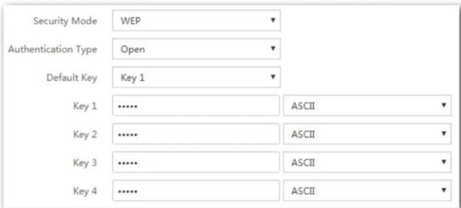
text_image
Security Mode WEP Authentication Type Open Default Key Key 1 ASCII Key 2 ASCII Key 3 ASCII Key 4 ASCIIParameter descripon
| Parameter | Descripon |
| Authencaon Type | It species the authencaon type for the WEP security mode. The opons includeOpen, Shared, and 802.1x.The opons share the same encrypon process.Open: It species that authencaon is not required and data exchanged is encrypted using WEP. In this case, a wireless client can connect to the wireless network corresponding to the selected SSID without being authenticated, and the data exchanged between the client and the network is encrypted in WEP security mode.Shared: It species that a shared key is used for authencaon and data exchanged is encrypted using WEP. In this case, a wireless client must use a preset WEP key to connect to the wireless network corresponding to the selected SSID. The wireless client can be connected to the wireless network only if they use the same WEP key.802.1xspecies that 802.1x authencaon is required and data exchanged is encrypted using WEP. In this case, ports are enabled for user authencaon when valid clients connect to the wireless network corresponding to the selected SSID, and disabled when invalid users connect to the wireless network. |
| Default Key | It species the WEP key for the Open or Shared encrypon type.For example, ifDefault Keyis set toSecurity Key 2, a wireless client can connect to the wireless network corresponding to the selected SSID only with the password specied bySecurity Key 2. |
| ASCII | It indicates that a key selected for the Open or Shared authencaon type contains hexadecimal characters.5 or 13 ASCII characters are allowed in the key. |
| Hex | It indicates that a key selected for the Open or Shared authencaon type contains hexadecimal characters.10 or 26 hexadecimal characters (range: 0-9, a-f, and A-F) are allowed in the key. |
| RADIUS Server | |
| RADIUS Port | These parameters are dedicated to the 802.1x authencaon type.It species the IP address/port number/shared key of the RADIUS server for authencaon. |
| RADIUS Password |
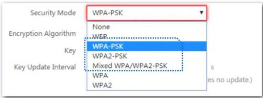
text_image
Security Mode WPA-PSK Encryption Algorithm None WEP Key WPA-PSK WPA2-PSK Mixed WPA/WPA2-PSK WPA WPA2 Key Update Interval s (ies no update.)Parameter descripon
| Parameter | Descripon |
| Security Mode | It indicates the personal or pre-shared key security mode, including WPA-PSK, WPA2-PSK, and Mixed WPA/WPA2-PSK.WPA-PSK: It indicates that the wireless network corresponding to the selected SSID is encrypted using WPA-PSK.WPA2-PSK: It indicates that the wireless network corresponding to the selected SSID is encrypted using WPA2-PSK.Mixed WPA/WPA2-PSK: It indicates that wireless clients can connect to the wireless network corresponding to the selected SSID using either WPA-PSK or WPA2-PSK. |
| Encrypon Algorithm | It species the encrypon algorithm corresponding to the selected security mode. If Security Mode is set to WPA-PSK, this parameter has the AES and TKIP values. If Security Mode is set to WPA2-PSK or Mixed WPA/WPA2-PSK, this parameter has the AES, TKIP, and TKIP&AES values.AES: It indicates the Advanced Encrypon Standard.TKIP: It indicates the Temporal Key Integrity Protocol. If TKIP is used, the maximum wireless throughput of the AP is limited to 54 Mbps.TKIP&AES: It indicates that both TKIP and AES encrypon algorithms are supported. Wireless clients can connect to the wireless network corresponding to the selected SSID using TKIP or AES. |
| Key | It species a pre-shared WPA key. A WPA key can contain 8 to 63 ASCII characters or 8 to 64 hexadecimal characters. |
| Key Update Interval | It species the automac update interval of a WPA key for data encrypon. A shorter interval results in higher data security.The value 0 indicates that a WAP key is not updated. |
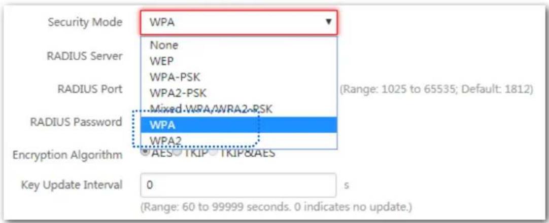
text_image
Security Mode WPA RADIUS Server None WEP WPA-PSK WPA2-PSK RADIUS Port Mixed.WPA/WRA2-RSK RADIUS Password WPA WPA2 Encryption Algorithm AES TKIP TKIP&AES Key Update Interval 0 (Range: 60 to 99999 seconds. 0 indicates no update.)Parameter descripon
| Parameter | Descripon |
| Security Mode | The WPA and WPA2 opons are available for network protecon with a RADIUS server.WPA: It indicates that the wireless network corresponding to the selected SSID is encrypted using WPA.WPA: It indicates that the wireless network corresponding to the selected SSID is encrypted using WPA. |
| RADIUS Server | It species the IP address of the RADIUS server for client authencaon. |
| RADIUS Port | It species the port number of the RADIUS server for client authencaon. |
| RADIUS Password | It species the shared password of the RADIUS server. |
| Encrypon Algorithm | It species the encrypon algorithm corresponding to the selected security mode. The available opons include AES, TKIP, and TKIP&AES.AES: It indicates the Advanced Encrypon Standard.TKIP: It indicates the Temporal Key Integrity Protocol.TKIP&AES: It indicates that both TKIP and AES encrypon algorithms are supported. Wireless clients can connect to the wireless network corresponding to the selected SSID using TKIP or AES. |
| Key Update Interval | It species the automac update interval of a WPA key for data encrypon. A shorter interval results in higher data security.The value 0 indicates that a WAP key is not updated. |
7.1.3 Examples of Conguring SSID Sengs
Seng up a Non-encrypted Wireless Network
Networking requirement
In a hotel lounge, guests can connect to the wireless network without a password and access the internet through the WiFi network.
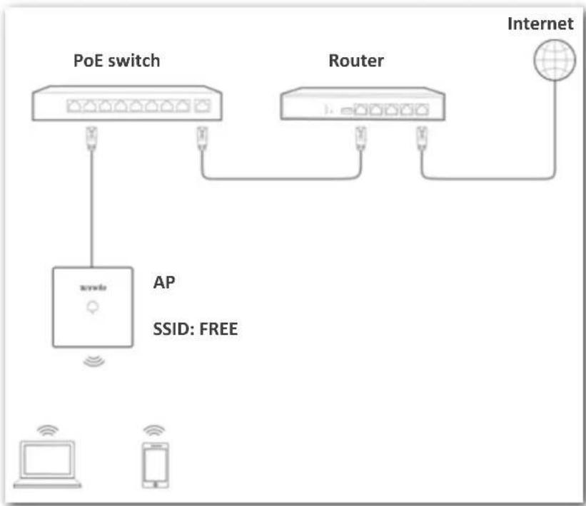
flowchart
graph TD
    A["PoE switch"] --> B["AP"]
    B --> C["SSID: FREE"]
    D["Router"] --> E["Internet"]
    F["Computer"] --> G["Mobile Device"]
    H["Smartphone"] --> I["Mobile Device"]
    J["Switch"] --> K["Switch"]
    L["Switch"] --> M["Switch"]
    N["Switch"] --> O["Switch"]
    P["Switch"] --> Q["Switch"]
    R["Switch"] --> S["Switch"]
    T["Switch"] --> U["Switch"]
    V["Switch"] --> W["Switch"]
    X["Switch"] --> Y["Switch"]
    Z["Switch"] --> AA["Switch"]
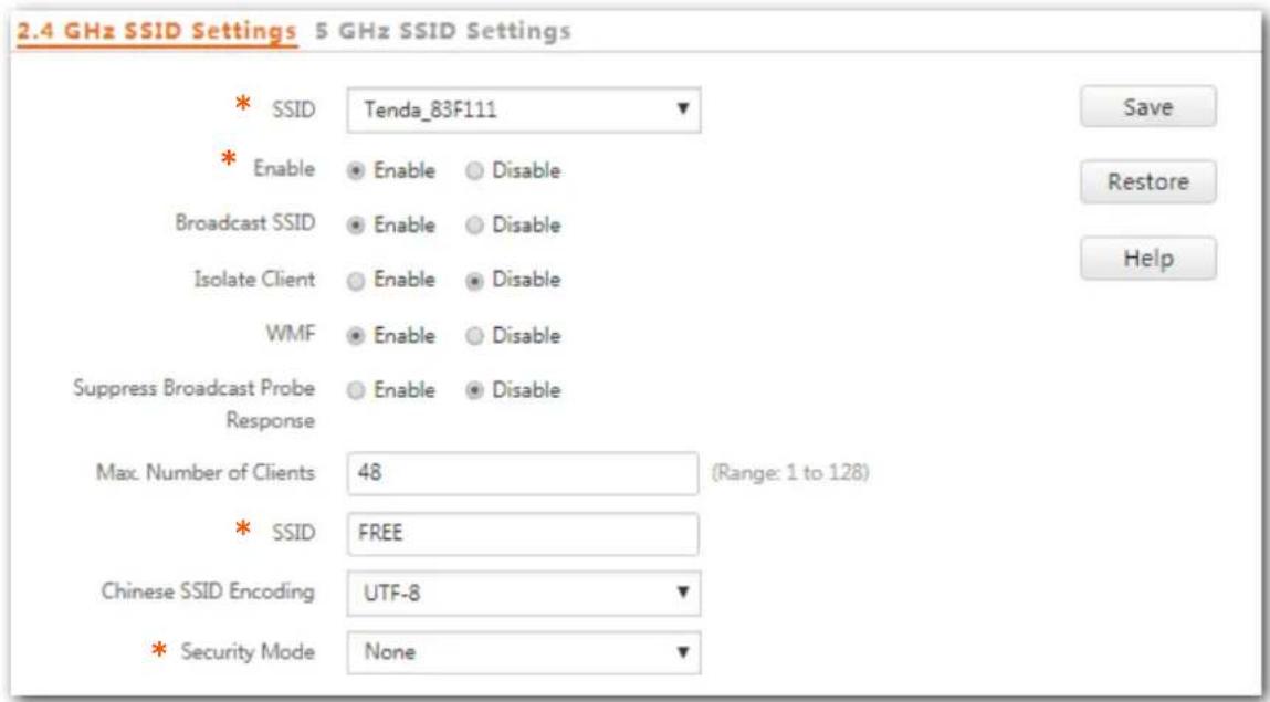
Conguraon procedure
Assume that the second SSID of the AP, the WPA2-PSK security mode, and AES encrypon algorithm are used.
Step 1 Choose Wireless Setng > SSID Sengs.
Step 2 Select the second SSID from the SSID drop-down list box.
Step 3 Select the Enable check box.
Step 4 Change the value of the SSID text box to FREE.
Step 5 Set Security Mode to None.
Step 6 Click Save.
text_image
2.4 GHz SSID Settings 5 GHz SSID Settings * SSID Tenda_83F111 * Enable Enable Disable Broadcast SSID Enable Disable Isolate Client Enable Disable WMF Enable Disable Suppress Broadcast Probe Enable Disable Response Max. Number of Clients 48 (Range: 1 to 128) * SSID FREE Chinese SSID Encoding UTF-8 * Security Mode None---End
Vericaon
Verify that wireless devices can connect to the FREE wireless network without a password.
Seng up a Wireless Network Encrypted Using WPA/WPA2-PSK
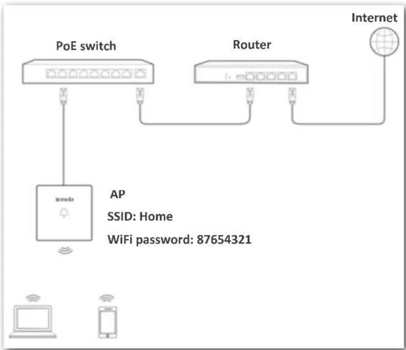
Networking requirement
A home wireless network with a certain level of security must be set up through a simply procedure. In this case, WPA/WPA2 pre-shared key mode is recommended. See the following gure.
flowchart
graph TD
    A["PoE switch"] --> B["Router"]
    B --> C["Internet"]
    D["AP"] -->|AP| B
    E["WiFi password: 87654321"] --> B
    F["Computer"] --> G["Mobile Device"]
    H["Smartphone"] --> I["Mobile Device"]
Conguraon procedure
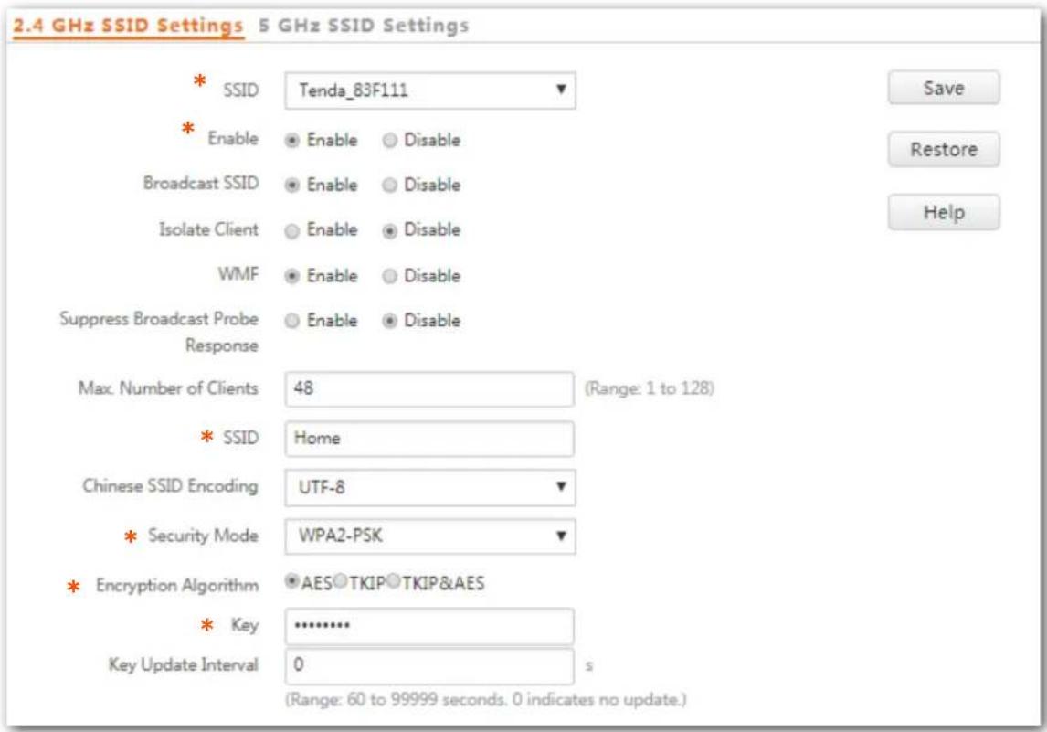
Assume that the second SSID of the AP, the WPA2-PSK security mode, and AES encrypon algorithm are used.
Step 1 Choose Wireless Setng > SSID Sengs.
Step 2 Select the second SSID from the SSID drop-down list box.
Step 3 Select the Enable check box.
Step 4 Change the value of the SSID text box to Home.
Step 5 Set Security Mode to WPA2-PSK and Encrypon Algorithm to AES.
Step 6 Set Key to 87654321.
Step 7 Click Save.
text_image
2.4 GHz SSID Settings 5 GHz SSID Settings * SSID Tenda_83F111 * Enable Enable Disable Broadcast SSID Enable Disable Isolate Client Enable Disable WMF Enable Disable Suppress Broadcast Probe Enable Disable Response Max. Number of Clients 48 (Range: 1 to 128) * SSID Home Chinese SSID Encoding UTF-8 * Security Mode WPA2-PSK * Encryption Algorithm AES TKIP TKIP&AES * Key .......... Key Update Interval 0 s (Range: 60 to 99999 seconds. 0 indicates no update.)---End
Vericaon
Verify that wireless devices can connect to the Home wireless network with the password 87654321.
Seng up a Wireless Network Encrypted Using WPA or WPA2
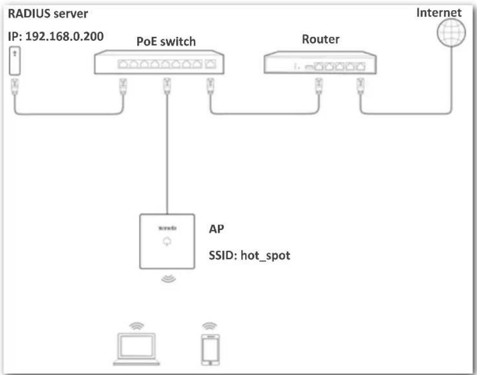
Networking requirement
A highly secure wireless network is required and a RADIUS server is available. In this case, WPA or WPA2 pre-shared key mode is recommended. See the following gure.
flowchart
graph TD
    A["RADIUS server"] -->|IP: 192.168.0.200| B["PoE switch"]
    B --> C["Router"]
    C --> D["Internet"]
    B --> E["AP"]
    B --> F["SSID: hot_spot"]
    E --> G["Computer"]
    F --> H["Mobile Device"]
Conguraon procedure
Congure the AP
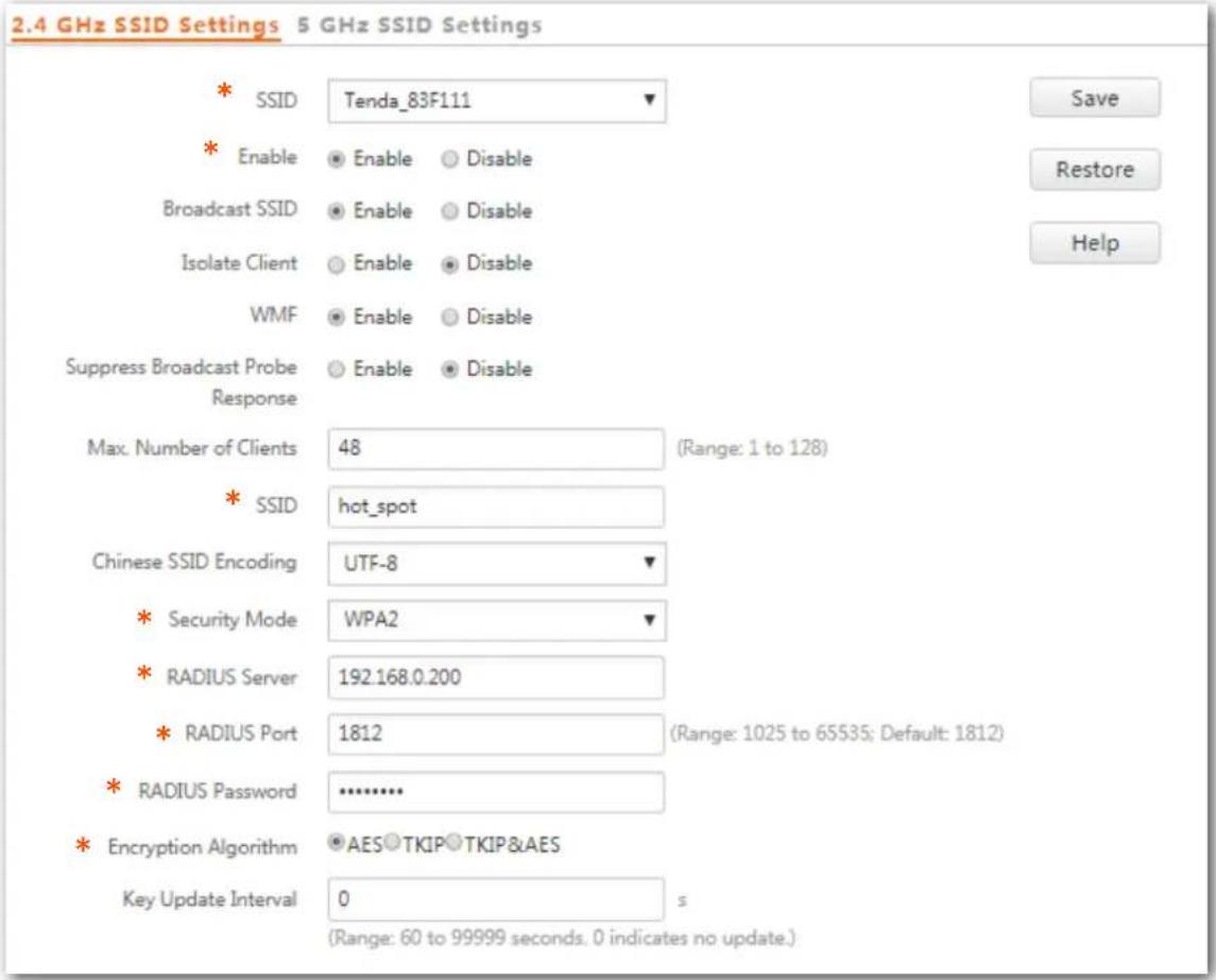
Assume that the IP address of the RADIUS server is 192.168.0.200, the Key is 12345678, and the port number for authencaon is 1812.
Assume that the second SSID of the AP is used.
Step 1 Choose Wireless Setng > SSID Sengs.
Step 2 Select the second SSID from the SSID drop-down list box.
Step 3 Select the Enable check box.
Step 4 Change the value of the SSID text box to hot_spot.
Step 5 Set Security Mode to WPA2.
Step 6 Set RADIUS Server IP, RADIUS Port, and RADIUS Password to 192.168.0.200, 1812, and 12345678 respectively.
Step 7 Set Encrypon Algorithm to AES.
Step 8 Click Save.
text_image
2.4 GHz SSID Settings 5 GHz SSID Settings * SSID Tenda_83F111 * Enable Enable Disable Broadcast SSID Enable Disable Isolate Client Enable Disable WMF Enable Disable Suppress Broadcast Probe Enable Disable Response Max. Number of Clients 48 (Range: 1 to 128) * SSID hot_spot Chinese SSID Encoding UTF-8 * Security Mode WPA2 * RADIUS Server 192.168.0.200 * RADIUS Port 1812 (Range: 1025 to 65535; Default: 1812) * RADIUS Password .......... * Encryption Algorithm AES TKIP TKIP&AES Key Update Interval 0 s (Range: 60 to 99999 seconds. 0 indicates no update.)---End
Congure the RADIUS server

Windows 2003 is used as an example to describe how to congregate the RADIUS server.
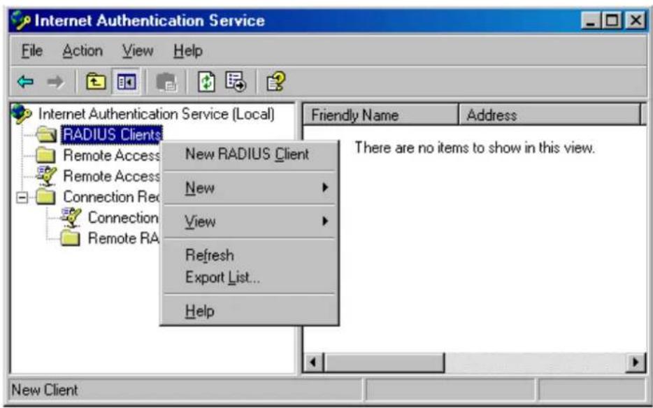
Step 1 Congure a RADIUS client.
- In the Computer Management dialog box, double-click Internet Authencaon Service, right-click RADIUS Clients, and choose New RADIUS Client.
text_image
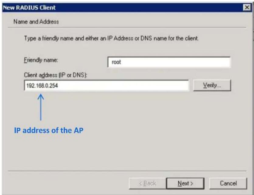
Internet Authentication Service File Action View Help Internet Authentication Service (Local) RADIUS Clients Remote Access Remote Access Connection Rec Connection Remote RA New RADIUS Client New View Refresh Export List... Help Friendly Name Address There are no items to show in this view. New Client- Enter a RADIUS client name (which can be the name of the AP) and the IP address of the AP, and click Next.
text_image
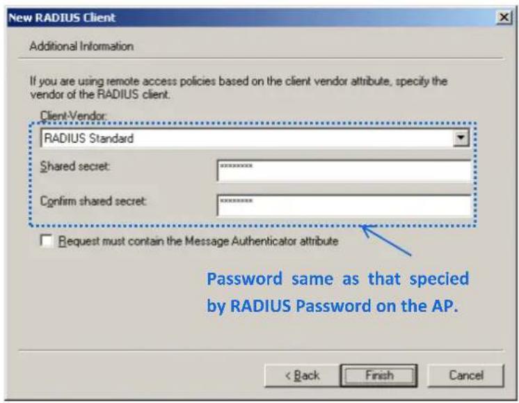
New RADIUS Client Name and Address Type a friendly name and either an IP Address or DNS name for the client. Friendly name: root Client address (IP or DNS): 192.168.0.254 Verify... IP address of the AP < Back Next > Cancel- Enter 12345678 in the Shared secret and Conrm shared secret text boxes, and click Finish.
text_image
New RADIUS Client Additional Information If you are using remote access policies based on the client vendor attribute, specify the vendor of the RADIUS client. Client-Vendor: RADIUS Standard Shared secret: ********** Confirm shared secret: ********** Request must contain the Message Authenticator attribute Password same as that specied by RADIUS Password on the AP. < Back Finish CancelStep 2 Congure a remote access policy.
- Right-click Remote Access Policies and choose New Remote Access Policy.
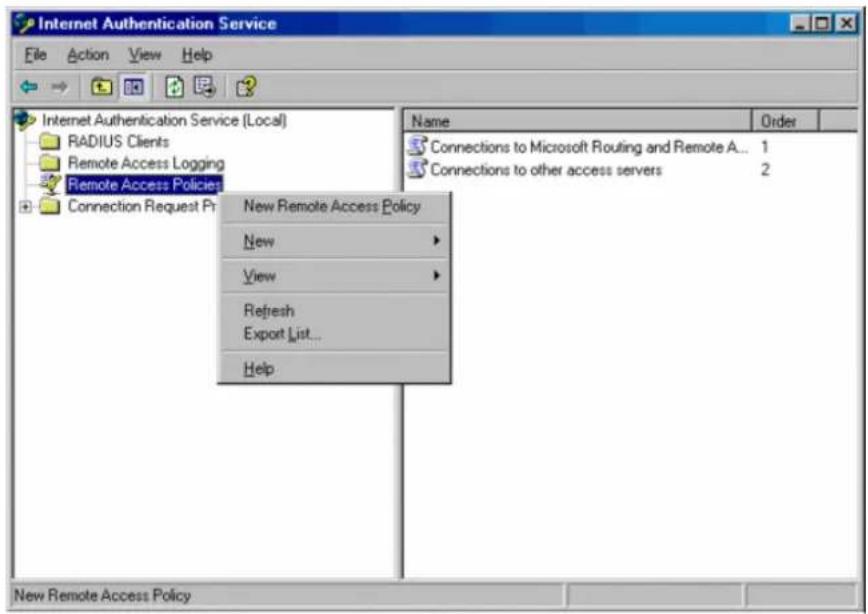
text_image
Internet Authentication Service File Action View Help Internet Authentication Service (Local) RADIUS Clients Remote Access Logging Remote Access Policies Connection Request Pr New Remote Access Policy New View Refresh Export List... Help Name Order Connections to Microsoft Routing and Remote A... 1 Connections to other access servers 2 New Remote Access Policy New View Refresh Export List... Help- In the New Remote Access Policy Wizard dialog box that appears, click Next.
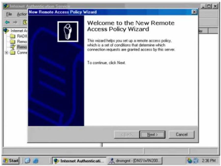
text_image
New Remote Access Policy Wizard Welcome to the New Remote Access Policy Wizard This wizard helps you set up a remote access policy, which is a set of conditions that determine which connection requests are granted access by this server. To continue, click Next. < Back Next > Cancel Start Internet Authenticati... dnsmgmt - [DNS\WIN200... 2:36 PM- Enter a policy name and click Next.
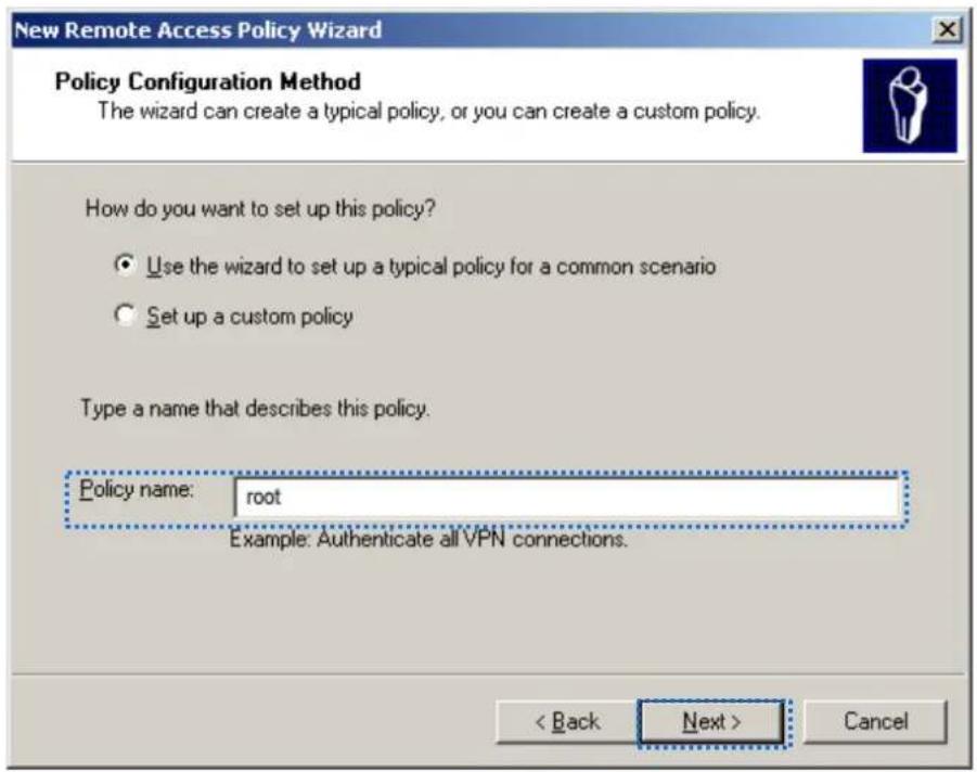
text_image
New Remote Access Policy Wizard Policy Configuration Method The wizard can create a typical policy, or you can create a custom policy. How do you want to set up this policy? Use the wizard to set up a typical policy for a common scenario Set up a custom policy Type a name that describes this policy. Policy name: root Example: Authenticate all VPN connections. < Back Next > Cancel4. Select Ethernet and click Next.
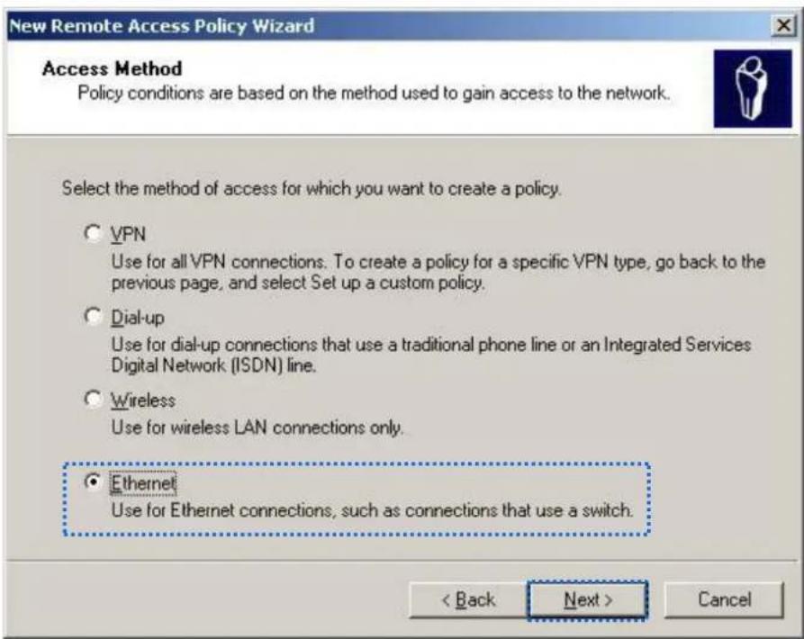
text_image
New Remote Access Policy Wizard Access Method Policy conditions are based on the method used to gain access to the network. Select the method of access for which you want to create a policy. ○ VPN Use for all VPN connections. To create a policy for a specific VPN type, go back to the previous page, and select Set up a custom policy. ○ Dial-up Use for dial-up connections that use a traditional phone line or an Integrated Services Digital Network (ISDN) line. ○ Wireless Use for wireless LAN connections only. ● Ethernet Use for Ethernet connections, such as connections that use a switch. < Back Next > Cancel5. Select Group and click Add.
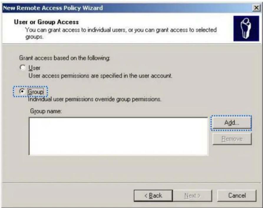
text_image
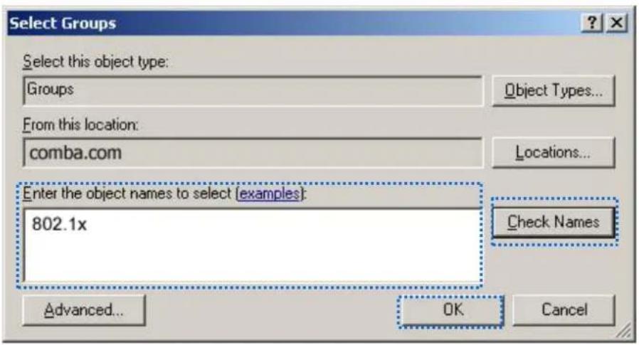
New Remote Access Policy Wizard User or Group Access You can grant access to individual users, or you can grant access to selected groups. Grant access based on the following: ○ User User access permissions are specified in the user account. ● Group Individual user permissions override group permissions. Group name: Add... Remove < Back Next > Cancel- Enter 802.1x in the Enter the object names to select text box, click Check Names, and click OK.
text_image
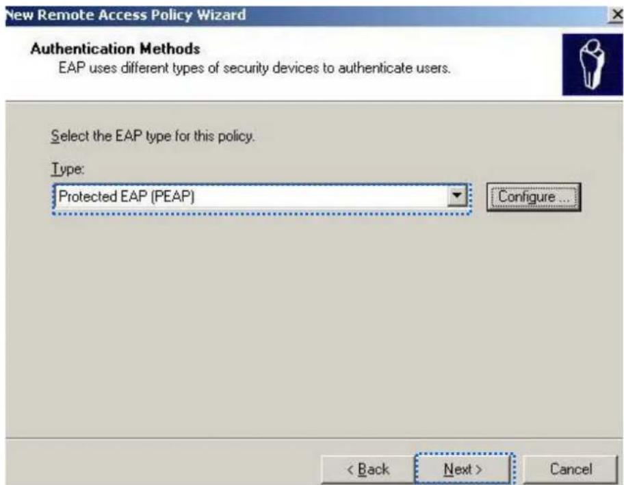
Select Groups Select this object type: Groups Object Types... From this location: comba.com Locations... Enter the object names to select (examples): 802.1x Check Names Advanced... OK Cancel- Select Protected EAP (PEAP) and click Next.
text_image
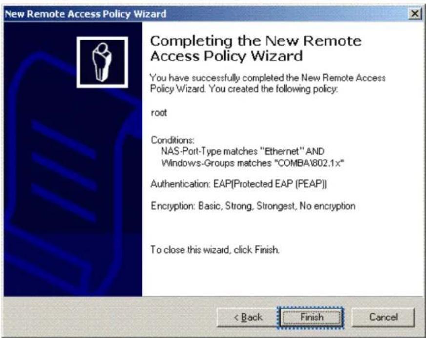
New Remote Access Policy Wizard Authentication Methods EAP uses different types of security devices to authenticate users. Select the EAP type for this policy. Type: Protected EAP (PEAP) Configure... < Back Next > Cancel- Click Finish. The remote access policy is created.
text_image
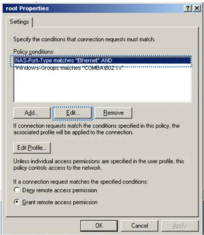
New Remote Access Policy Wizard Completing the New Remote Access Policy Wizard You have successfully completed the New Remote Access Policy Wizard. You created the following policy: root Conditions: NAS-Port-Type matches "Ethernet" AND Windows-Groups matches "COMBA\802.1x" Authentication: EAP(Protected EAP (PEAP)) Encryption: Basic, Strong, Strongest, No encryption To close this wizard, click Finish. < Back Finish Cancel- Right-click root and choose Properes. Select Grant remote access permission, select NAS-Port-Type matches "Ethernet" AND, and click Edit.
text_image
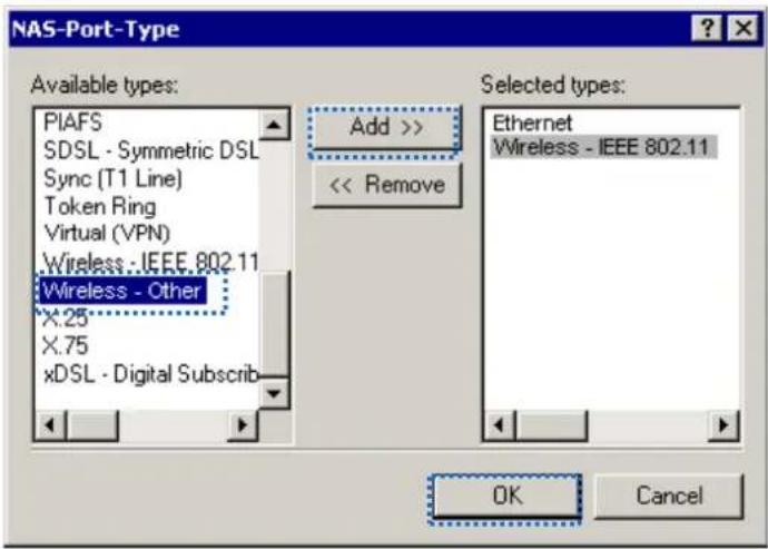
root Properties Settings Specify the conditions that connection requests must match. Policy conditions: NAS-Port-Type matches "Ethernet" AND "windows-Groups matches "COMBA\02:1x" Add... Edit... Remove If connection requests match the conditions specified in this policy, the associated profile will be applied to the connection. Edit Profile... Unless individual access permissions are specified in the user profile, this policy controls access to the network. If a connection request matches the specified conditions: Deny remote access permission Grant remote access permission OK Cancel Apply10. Select Wireless – Other, click Add, and click OK.
text_image
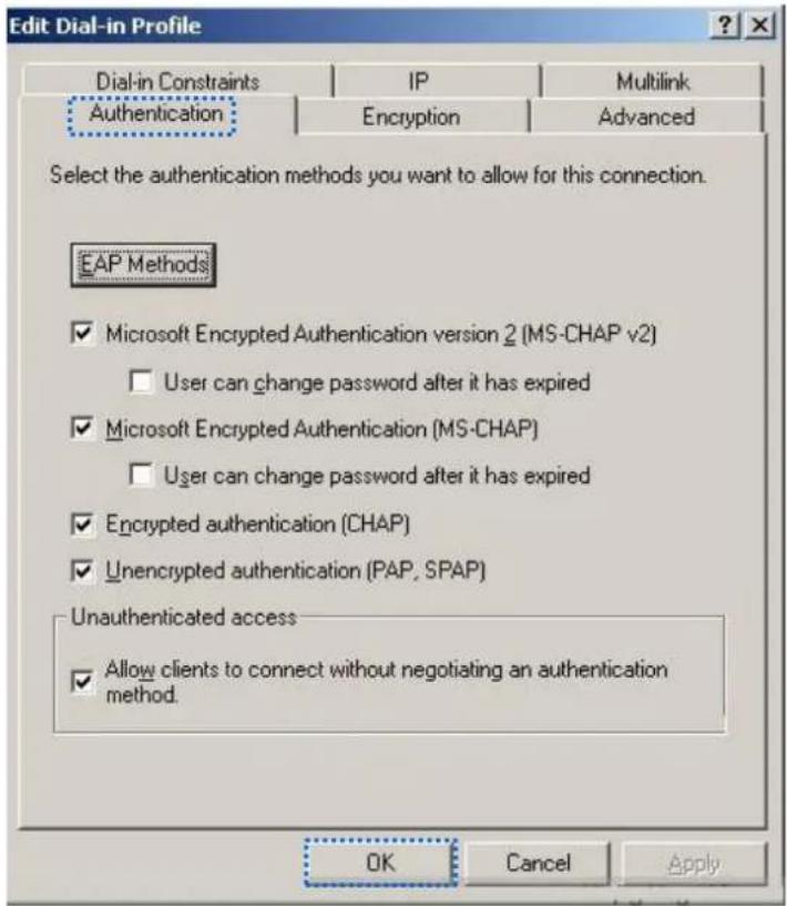
NAS-Port-Type Available types: PIAFS SDSL - Symmetric DSL Sync (T1 Line) Token Ring Virtual (VPN) Wireless - IEEE 802.11 Wireless - Other X:25 X:75 xDSL - Digital Subscrib Add >> << Remove Selected types: Ethernet Wireless - IEEE 802.11 OK Cancel11. Click Edit Prole, click the Authencaon tab, congure sengs as shown in the following gure, and click OK.
text_image
Edit Dial-in Profile Dial-in Constraints IP Multilink Authentication Encryption Advanced Select the authentication methods you want to allow for this connection. EAP Methods ✓ Microsoft Encrypted Authentication version 2 (MS-CHAP v2) □ User can change password after it has expired ✓ Microsoft Encrypted Authentication (MS-CHAP) □ User can change password after it has expired ✓ Encrypted authentication (CHAP) ✓ Unencrypted authentication (PAP, SPAP) Unauthenticated access ✓ Allow clients to connect without negotiating an authentication method. OK Cancel Apply12. When a message appears, click No.
Step 3 Congure user informaon.
Create a user and add the user to group 802.1x.
---End

Windows 7 is taken as an example to describe the procedure.
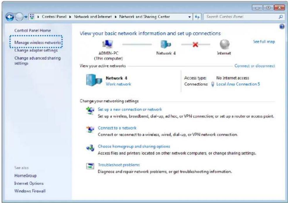
Step 1 Choose Start > Control Panel, click Network and Internet, click Network and Sharing Center, and click Manage wireless networks.
text_image
Control Panel Home Manage wireless networks Change adapter settings Change advanced sharing settings View your basic network information and set up connections ADMIN-PC (This computer) Network 4 Internet View your active networks Connect or disconnect Network 4 Work network Access type: No internet access Connections: Local Area Connection 5 Change your networking settings Set up a new connection or network Set up a wireless, broadband, dial-up, ad hoc, or VPN connection; or set up a router or access point. Connect to a network Connect or reconnect to a wireless, wired, dial-up, or VPN network connection. Choose homegroup and sharing options Access files and printers located on other network computers, or change sharing settings. Troubleshoot problems Diagnose and repair network problems, or get troubleshooting information. See also HomeGroup Internet Options Windows FirewallStep 2 Click Add.
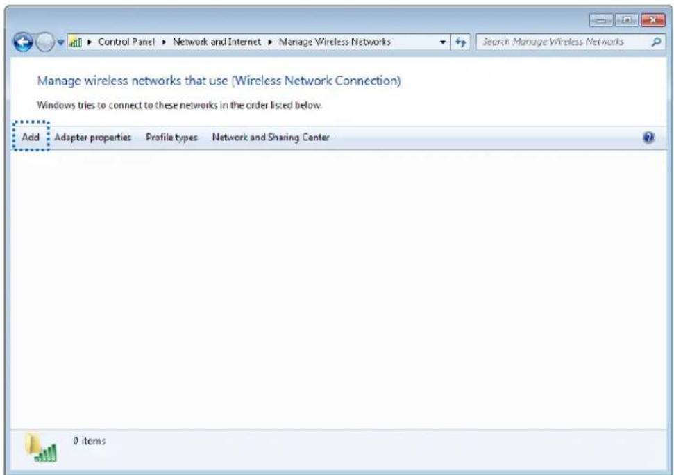
text_image
Control Panel ▶ Network and Internet ▶ Manage Wireless Networks Manage wireless networks that use (Wireless Network Connection) Windows tries to connect to these networks in the order listed below. Add Adapter properties Profile types Network and Sharing Center 0 itemsStep 3 Click Manually create a network prole.
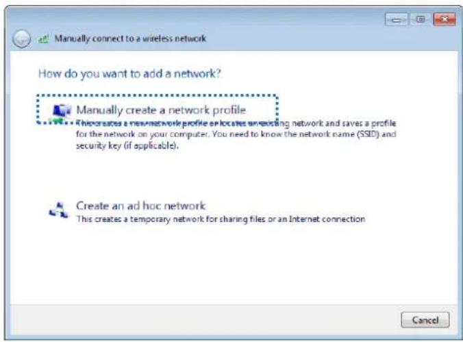
text_image
Manually connect to a wireless network How do you want to add a network? Manually create a network profile This creates a new or existing network and saves a profile for the network on your computer. You need to know the network name (SSID) and security key (if applicable). Create an ad hoc network This creates a temporary network for sharing files or an Internet connection CancelStep 4 Enter wireless network informaon, select Connect even if the network is not broadcasting, and click Next.

text_image
Manually connect to a wireless network Enter information for the wireless network you want to add Network name: hot_spot Security type: WPA2-Enterprise Encryption type: AES Security Key: Same as the security mode of the SSID of the AP Hide characters ✓ Start this connection automatically ✓ Connect even if the network is not broadcasting Warning: If you select this option, your computer's privacy might be at risk. Next CancelStep 5 Click Change conncon setngs.
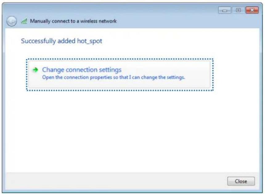
text_image
Manually connect to a wireless network Successfully added hot_spot Change connection settings Open the connection properties so that I can change the settings. CloseStep 6 Click the Security tab, select Microso: Protected EAP (PEAP), and click Sengs.
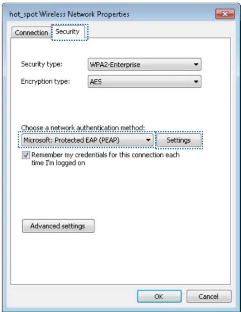
text_image
hot_spot Wireless Network Properties Connection Security Security type: WPA2-Enterprise Encryption type: AES Choose a network authentication method: Microsoft: Protected EAP (PEAP) Settings ✓ Remember my credentials for this connection each time I'm logged on Advanced settings OK CancelStep 7 Deselect Validate server cercate and click Congure.
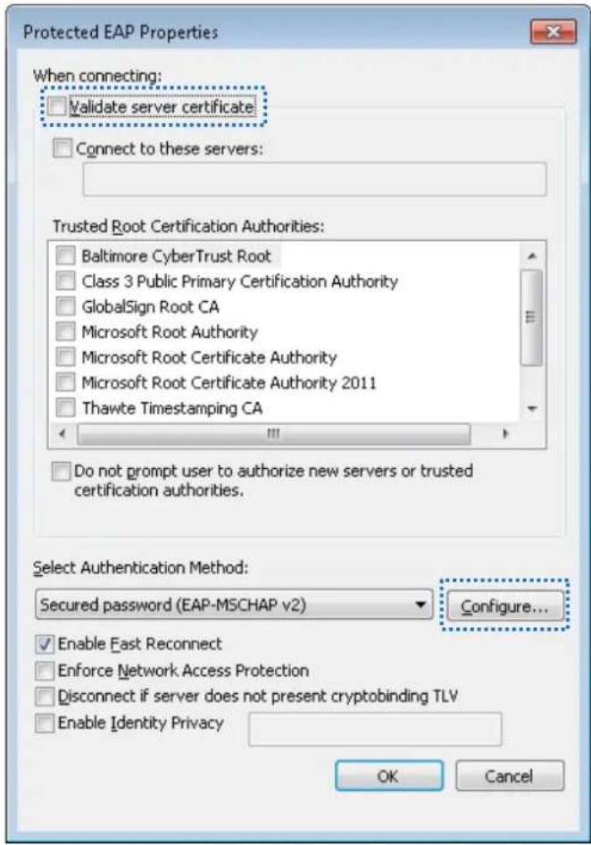
text_image
Protected EAP Properties When connecting: Validate server certificate Connect to these servers: Trusted Root Certification Authorities: Baltimore CyberTrust Root Class 3 Public Primary Certification Authority GlobalSign Root CA Microsoft Root Authority Microsoft Root Certificate Authority Microsoft Root Certificate Authority 2011 Thawte Timestamping CA Do not prompt user to authorize new servers or trusted certification authorities. Select Authentication Method: Secured password (EAP-MSCHAP v2) Configure... Enable Fast Reconnect Enforce Network Access Protection Disconnect if server does not present cryptobinding TLV Enable Identity Privacy OK CancelStep 8 Deselect Automacally use my Windows logon name and password (and domain if any) and click OK.
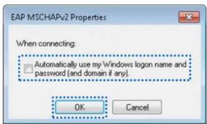
text_image
EAP MSCHAPv2 Properties When connecting: □ Automatically use my Windows logon name and password (and domain if any). OK CancelStep 9 Click Advanced setngs.
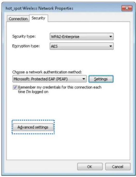
text_image
hot_spot Wireless Network Properties Connection Security Security type: WPA2-Enterprise Encryption type: AES Choose a network authentication method: Microsoft: Protected EAP (PEAP) Settings Remember my credentials for this connection each time I'm logged on Advanced settings OK CancelStep 10 Select User or computer authencaon and click OK.
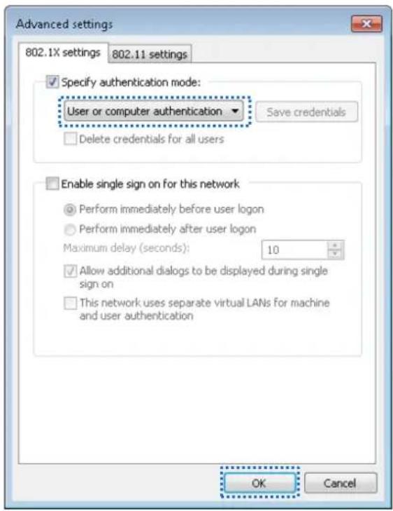
text_image
Advanced settings 802.1X settings 802.11 settings Specify authentication mode: User or computer authentication ▼ Save credentials Delete credentials for all users Enable single sign on for this network Perform immediately before user logon Perform immediately after user logon Maximum delay (seconds): 10 Allow additional dialogs to be displayed during single sign on This network uses separate virtual LANs for machine and user authentication OK CancelStep 11 Click Close.
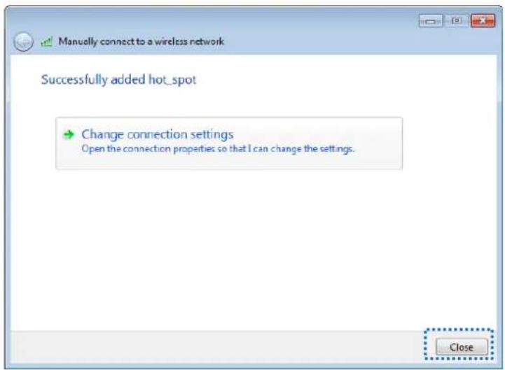
text_image
Manually connect to a wireless network Successfully added hot_spot Change connection settings Open the connection properties so that I can change the settings. Close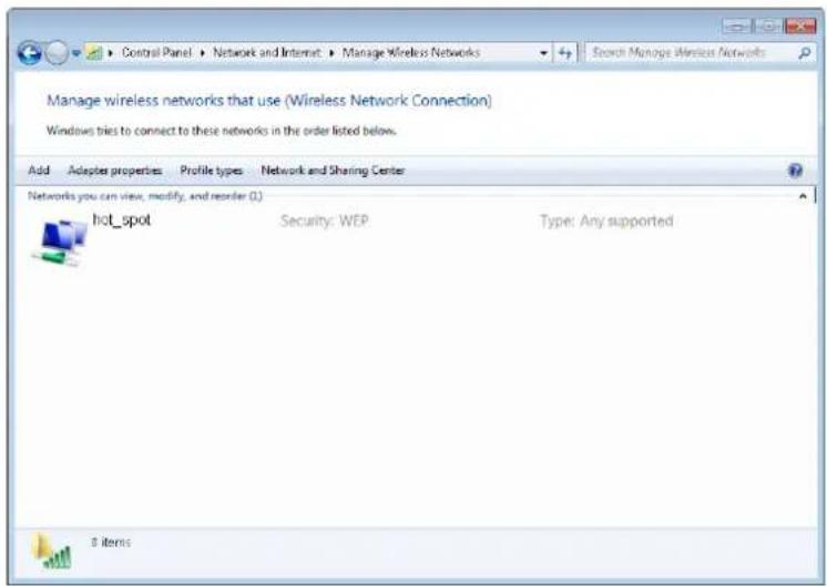
text_image
Manage wireless networks that use (Wireless Network Connection) Windows tries to connect to these networks in the order listed below. Add Adaptes properties Profile types Network and Sharing Center Networks you can view, modify, and reorder (L) hot_spot Security: WEP Type: Any supported 0 itemsStep 12 Click the network icon in the lower-right corner of the desktop and choose the wireless network of the AP, such as hot_spot in this example.
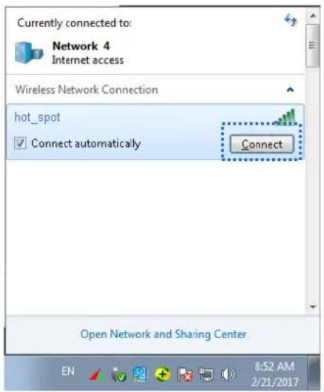
text_image
Currently connected to: Network 4 Internet access Wireless Network Connection hot_spot Connect automatically Connect Open Network and Sharing Center 8:52 AM 2/21/2017Step 13 In the Windows Security dialog box that appears, enter the user name and password set on the RADIUS server and click OK.
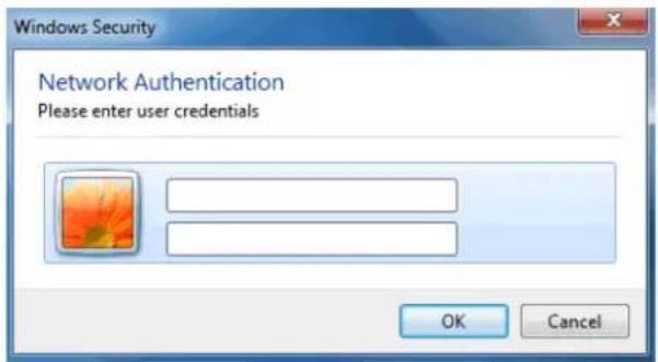
text_image
Windows Security Network Authentication Please enter user credentials OK Cancel---End
Vericaon
Wireless devices can connect to the wireless network named hot_spot.
7.2 Radio Sengs
7.2.1 Overview
This module is used to set Radio parameters of the AP. The following brief describes the SSID isolaon funcon.
SSID isolaon
This funcon isolates the wireless clients connected to dierent wireless networks of the AP. For example, if user 1 connects to the wireless network corresponding to SSID1, whereas user 2 connects to the wireless network corresponding to SSID2, the two users cannot communicate with each other aer SSID isolaon is implemented.
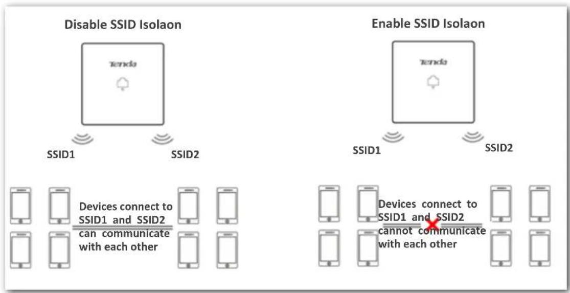
flowchart
graph TD
    A["Disable SSID Isolaon"] --> B["τendo"]
    B --> C["SSID1"]
    B --> D["SSID2"]
    E["Enable SSID Isolaon"] --> F["τendo"]
    F --> G["SSID1"]
    F --> H["SSID2"]
    I["Devices connect to SSID1 and SSID2 can communicate with each other"] --> J["Mobile 1"]
    I --> K["Mobile 2"]
    L["Devices connect to SSID1 and SSID2 cannot communicate with each other"] --> M["Mobile 3"]
    N["Mobile 4"] --> O["Mobile 5"]
7.2.2 Modifying Radio Sengs
Step 1 Choose Wireless Setng > Radio Sengs.
Step 2 Choose the radio band to be congured, which is 2.4 GHz Radio Band Sengs in this example.
Step 3 Change the parameters as required. To change the Country/Region parameter, please unselect the Channel Lockout at rst.
Step 4 Click Save.
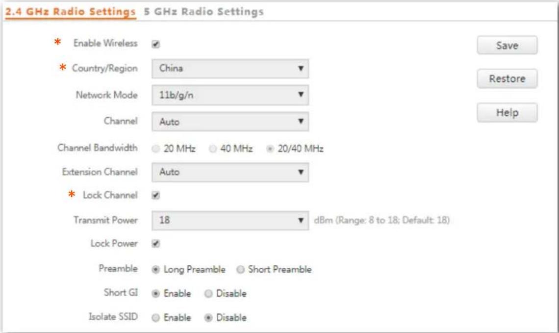
text_image
2.4 GHz Radio Settings 5 GHz Radio Settings * Enable Wireless ✓ * Country/Region China ✓ Network Mode 11b/g/n ✓ Channel Auto ✓ Channel Bandwidth 20 MHz 40 MHz 20/40 MHz Extension Channel Auto ✓ * Lock Channel ✓ Transmit Power 18 dBm (Range: 8 to 18; Default: 18) Lock Power ✓ Preamble Long Preamble Short Preamble Short GI Enable Disable Isolate SSID Enable Disable---End
Parameter descripon
| Parameter | Descripon |
| Enable Wireless | It species whether to enable the wireless funcon of the AP. |
| Country/Region | It species the country or region where the AP is used. This parameter helps comply with channel regulaons of the country or region. The default value is China. |
| Network Mode | It species the wireless network mode of the AP. Available opons include 11b/g/n mixed, 11b, 11g, 11b/g/n mixed. This parameter can be set if Channel Lockout is not selected.11b: The AP works in 802.11b mode and only wireless devices compliant with 802.11b can connect to the 2.4 GHz wireless networks of the AP.11g: The AP works in 802.11g mode and only wireless devices compliant with 802.11g can connect to the 2.4 GHz wireless networks of the AP.11b/g: The AP works in 802.11b/g mode and only wireless devices compliant with 802.11b or 802.11g can connect to the 2.4 GHz wireless networks of the AP.11b/g/n: The AP works in 802.11b/g/n mode. Wireless devices compliant with 802.11b or 802.11g and wireless devices working at 2.4 GHz and compliant with 802.11n can connect to the 2.4 GHz wireless networks of the AP.11a: The AP works in 802.11a mode and only wireless devices compliant with 802.11a can connect to the 5 GHz wireless networks of the AP.11ac: The AP works in 802.11ac mode and only wireless devices compliant with 802.11ac can connect to the 5 GHz wireless networks of the AP.11a/n: The AP works in 802.11a/n mode and only wireless devices compliant with 802.11a or 802.11n can connect to the 5 GHz wireless networks of the AP. |
| Channel | It species the operang channel of the AP. This parameter can be set if Channel Lockout is not selected.Auto: It indicates that the AP automacally adjusts its operang channel according to the ambient environment. |
| Channel Bandwidth | It species the wireless channel bandwidth of the AP. This parameter can be set if the AP works in 802.11 b/g/n, 802.11ac, 802.11a/n mode and Channel Lockout is not selected.20 MHz: It indicates that the AP can use only 20 MHz channel bandwidth.40 MHz: It indicates that the AP uses 40 MHz channel bandwidth rst, and changes to 20 MHz channel bandwidth if severe channel compeon occurs in the ambient environment.20/40 MHz: It indicates that the AP automacally adjusts its channel bandwidth to 20 MHz or 40 MHz according to the ambient environment. |
| Extension Channel | It species the wireless expansion channel of the AP. This parameter can be set if the channel bandwidth of the AP is set to 40 or 20/40 and Channel Lockout is not selected. |
| Lock Channel | It is used to lock the channel sengs of the AP. If this parameter is selected, channel sengs including Country/Region, Network Mode, Channel, Channel Bandwidth, and Expansion Channel cannot be changed. |
| Transmit Power | It species the transmit power of the AP.A greater transmit power of the AP oers broader network coverage. You can slightly reduce the transmit power to improve the wireless network performance and security. |
| Lock Power | It species whether the current transmit power sengs of the AP can be changed. If it is selected, the sengs cannot be changed. |
| Preamble | A preamble is a group of bits located at the beginning of a packet to enable a receiver of the packet to perform synchronizaon and prepare for receiving data.By default, the Long Preamble opon is selected for compatibility with old network adapters installed on wireless clients. To achieve beer synchronizaon performance of networks, you can select the Short Preamble opon. |
| Short GI | Short Guard Interval.There is a delay on the receiving side due to mulpath and other factors during the wireless signal transmission in space. If the subsequent data block is transmied too quickly, it will interfere with the previous data block, and the short guard interval can be used to circumvent this interference. Short GI helps to increase the wireless throughput by 10%. |
| Isolate SSID | It species whether to isolate the wireless clients connected to the AP with dierent SSIDs.Disable: It indicates that the wireless clients connected to the AP with dierent SSIDs can communicate with each other.Enable: It indicates that the wireless clients connected to the AP with dierent SSID cannot communicate with each other. This improves wireless network security. |
7.3 Radio Opmizaon
7.3.1 Overview
Applicaon Scenarios
Generally, wireless networks are widely applied to the following two scenarios:
Ordinary scenario
For areas that demand wide WiFi coverage, such as oces, public buildings, schools, warehouses and hospitals.
■ High density scenario
For large crowded areas, such as:
– Conference halls, theaters, exhibition and banquet halls
- Indoor and open stadiums
– Classrooms at colleges and universities
– Airports and railway staons
Radio Opmizaon Parameters
To address the demands of both coverage-oriented and high-density scenarios, the AP provides a series of parameters for radio opmizaon, facilitang our customers to create qualified wireless network service.
Priorize 5 GHz
Although the 2.4 GHz band is more widely used than the 5 GHz band in actual wireless networks applicaon, channels and signals on 2.4 GHz suer more serious congeson and interference since there are only 3 non-overlapped communicaon channels on this band. The 5 GHz band could provide more non-overlapped communicaon channels. The quantity could reach more than 20 in some countries.
With the evolvement of the wireless networks, wireless clients that support both the 2.4 GHz and 5 GHz are more popular. However, by default, such dual-band wireless clients choose the 2.4 GHz to connect, resulting in even worse congestion of the 2.4 GHz band and the waste of the 5 GHz band.
The priorize 5 GHz funcons enables such dual-band wireless clients to connect the 5 GHz band on network inializaon if the 5 GHz signal strength the AP received reaches or exceeds the 5 GHz threshold so as to improve the ulizaon of the 5 GHz band, reduce the load and interference on the 2.4 GHz band, thus beering user experience.
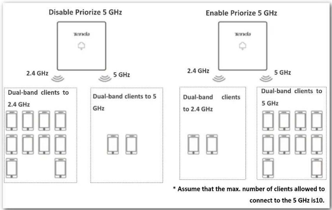
flowchart
graph TD
    A["Disable Priorize 5 GHz"] --> B["Dual-band clients to 2.4 GHz"]
    A --> C["Dual-band clients to 5 GHz"]
    D["Enable Priorize 5 GHz"] --> E["Dual-band clients to 2.4 GHz"]
    D --> F["Dual-band clients to 5 GHz"]
    B --> G["Mobile devices"]
    C --> H["Mobile devices"]
    E --> I["Mobile devices"]
    F --> J["Mobile devices"]
    style A fill:#f9f,stroke:#333
    style D fill:#f9f,stroke:#333
    style B fill:#ccf,stroke:#333
    style C fill:#ccf,stroke:#333
    style E fill:#ccf,stroke:#333
    style F fill:#ccf,stroke:#333
NOTE
The priorize 5 GHz funcon takes effect only on the condition that the wireless both of the 2.4 GHz and 5 GHz are enabled, and the two bands share the same SSID, security mode and password.
Air Interface Scheduling
In mixed wireless rates environment, the tradional FIFO (First-in First-out) allocates more air interface me to clients with low transmission capacity and low spectrum efficiency, reducing the system throughput of each AP then the system ulizaon.
The air interface scheduling funcon evenly allocates downlink transmission me to clients so that clients with high transmission rate could transmit more data, improving the throughput of each AP and quantity of clients allowed to be connected.
7.3.2 Opmizing Radio
NOTE
You are recommended to retain the default sengs if without the professional guidance.
Step 1 Choose Wireless Setng > Radio Opmization.
Step 2 Click the tab to choose the radio band to be congured.
Step 3 Change parameters as needed.
Step 4 Click Save.
2.4 GHz Radio Optimization 5 GHz Radio Optimization
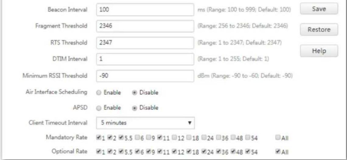
text_image
Beacon Interval 100 ms (Range: 100 to 999; Default: 100) Save Fragment Threshold 2346 (Range: 256 to 2346; Default: 2346) Restore RTS Threshold 2347 (Range: 1 to 2347; Default: 2347) DTIM Interval 1 (Range: 1 to 255; Default: 1) Help Minimum RSSI Threshold -90 dBm (Range: -90 to -60; Default: -90) Air Interface Scheduling Enable Disable APSD Enable Disable Client Timeout Interval 5 minutes ▼ Mandatory Rate ✓1 ✓2 ✓5.5 ☐6 ✓9 ✓11 ☐12 ☐18 ☐24 ☐36 ☐48 ☐54 All Optional Rate ✓1 ✓2 ✓5.5 ✓6 ✓9 ✓11 ✓12 ✓18 ✓24 ✓36 ✓48 ✓54 All---End
Parameter descripon
| Parameter | Descripon |
| Beacon Interval | Used to set the interval at which this device sends Beacon frames. |
| Beacon frames are sent at the interval to announce the existence of a wireless network. Generally, a smaller interval allows wireless clients to connect to this device sooner, while a larger interval allows the wireless network to transmit data quicker. | |
| Fragment Threshold | Threshold of a fragment. |
| Fragmening is a process that divides a frame into several fragments, which are transmied and acknowledged separately. If the size of a frame exceeds this threshold, the frame is fragmented. | |
| In case of a high error rate, you can reduce the threshold to enable this device to resend only the fragments that have not been sent successfully, so as to increase the frame throughput. | |
| In an environment with little interference, you can increase the threshold to reduce the number of frames, so as to increase the frame throughput. | |
| RTS Threshold | Frame length threshold for triggering the RTS/CTS mechanism. The unit is byte. |
| If a frame exceeds this threshold, the RTS/CTS mechanism is triggered to reduce conicts. | |
| Set the RTS threshold based on the actual situation. An excessively small value increases the RTS frame transmission frequency and bandwidth requirement. A higher RTS frame transmission frequency enables a wireless network to recover from conicts quicker. For a wireless network with high user density, you can reduce this threshold for reduce conicts. | |
| The RTS mechanism requires some network bandwidth. Therefore, it is triggered only when frames exceed this threshold. | |
| DTIM Interval | Countdown before this device transmits broadcast and mulcast frames in its cache. The unit is Beacon interval. |
| For example, if DTIM Interval is set to 1, this device transmits all cached frames at one Beaconinterval. | |
| Minimum RSSI Threshold | Minimum strength of received signals acceptable to this device. If the strength of the signals transmied by a wireless device is weaker than this threshold, the wireless device cannot connect to this device.A proper value facilitates wireless devices to connect to the AP with stronger signal in case of mulple APs exist. |
| Priorize 5 GHz | Enable: Dual band wireless devices prefer the 5 GHz WiFi network of the AP to connect.Disable: Dual band wireless devices connect to either 2.4 GHz or 5 GHz WiFi network of the AP at random. |
| 5 GHz Threshold | With this funcon enabled, if the strength of the signals transmied by a wireless device is stronger than this threshold, the wireless device connects to the 5 GHz WiFi network. Otherwise, it connects to the 2.4 GHz WiFi network. |
| Air Interface Scheduling | Used to enable or disable the air interface scheduling funcon of the AP.This enables the users experiencing high download rates to download more data, so that this device can achieve higher system throughput and connect to a greater number of clients. |
| APSD | APSD: Automac Power Save Delivery. If it is enabled, the power consumpon of this device is reduced aer a specied period during which no trac is transmied or received. By default, it is disabled. |
| Client Timeout Interval | Used to set the wireless client disconncon interval of this device. The device disconnects from a wireless client if no trac is transmied or received by the wireless client within the interval. |
| Mandatory Rate | It species rates that wireless clients must support in order to connect to the wireless networks of this device. |
| Oponal Rate | It species the additional rates that the AP supports, which are oponal to wireless clients. |
7.4 WMM Sengs
7.4.1 Overview
802.11 networks oer wireless access services based on the Carrier Sense Mulple Access with Collision Avoidance (CSMA/CA) channel compeon mechanism, which allows all wireless clients to fairly compete for channels. All the services implemented over wireless networks share the same channel compeon parameters. Nevertheless, dierent services usually have dierent requirements for bandwidth, delay, and jier. This requires wireless networks to oer accessibility based on the services implemented over the networks.
WMM is a wireless QoS protocol used to ensure that packets with high priories are transmied rst. This ensures beer voice and video service experience over wireless networks.
WMM involves the following terms:
- Enhanced Distributed Channel Access (EDCA): It is a channel compeon mechanism to ensure that packets with higher priories are assigned more bandwidth and transmied earlier.
- Access Category (AC): The WMM mechanism divides WLAN traffic by priority in descending order into the AC-VO (voice stream), AC-VI (video stream), AC-BE (best eort), and AC-BK (background) access categories. The access categories use queues with different priorities to send packets. The WMM mechanism ensures that packets in queues with higher priorities have more opportunities to access channels.
According to the 802.11 protocol family, all devices listen on a channel before using the channel to send data. If the channel stays idle for or longer than a specied period, the devices wait a random backo period within the contenon window. The device whose backoff period expires rst can use the channel. The 802.11 protocol family applies the same backoff period and contenon window to all devices across a network to ensure that the devices have the same channel contenon opportunity.
EDCA Parameters
WMM changes the contenon mechanism of 802.11 networks by dividing packets into four ACs, among which the ACs with higher priories have more opportunities to access channels. The ACs help achieve different service levels.
WMM assigns each AC a set of EDCA parameters for channel contenon, including:
- Arbitraon Inter Frame Spacing Number (AIFSN): Different from the xed distributed inter-frame spacing (DIFS) specied in the 802.11 protocol family, AIFSN varies across ACs. A greater AIFSN indicates a longer backo period. See AIFS in the following gure.
- Contenon window minimum (CWmin) and contenon window maximum (CWmax) specify the average backo period. The period increases along with these two values. See the backo slots in the following gure.
- Transmission Opportunity (TXOP): It species the maximum channel use duraon aer successful channel contenon. The duraon increases along with this value. The value 0 indicates that a device can send only one packet through a channel aer winning contenon for the channel.
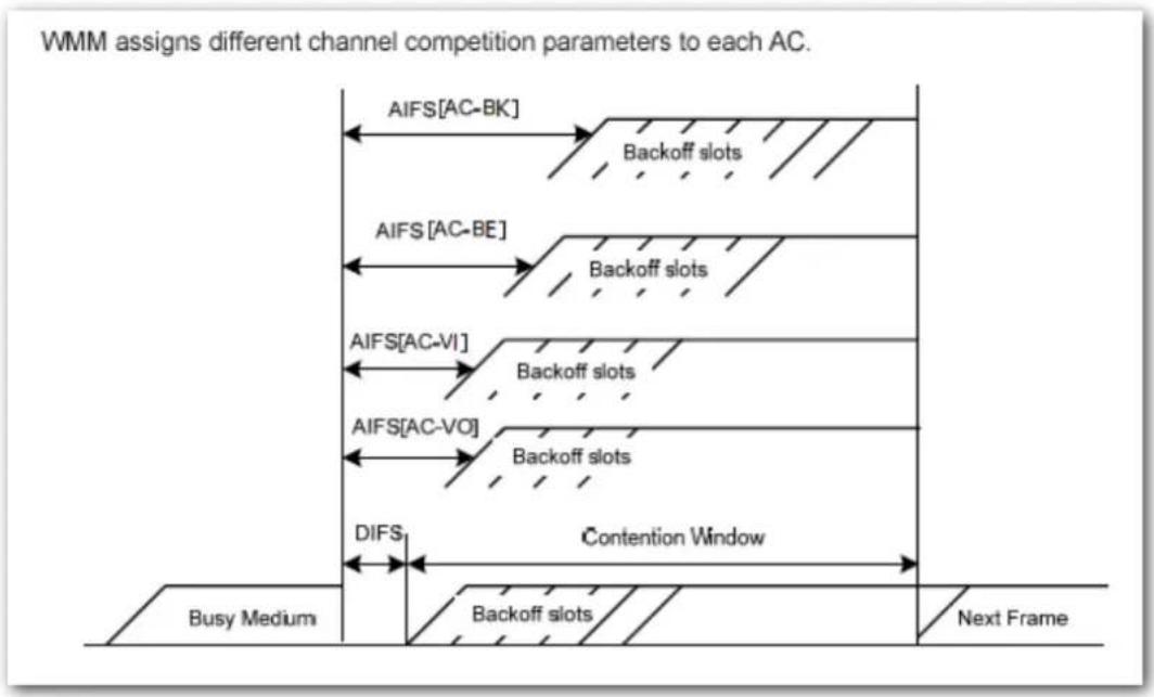
flowchart
graph TD
    A["Busy Medium"] --> B["AIFS[AC-BK"]]
    B --> C["Backoff slots"]
    D["Next Frame"] --> E["AIFS[AC-BE"]]
    E --> F["Backoff slots"]
    G["AIFS[AC-VI"]]
    F --> H["Backoff slots"]
    I["AIFS[AC-VO"]]
    H --> J["Backoff slots"]
    K["DIFS"] --> L["Contention Window"]
    M["Backoff slots"] --> N["Backoff slots"]
    style A fill:#f9f,stroke:#333
    style D fill:#f9f,stroke:#333
    style G fill:#f9f,stroke:#333
    style I fill:#f9f,stroke:#333
    style K fill:#ccf,stroke:#333
ACK Policies
WMM species the Normal ACK and No ACK policies.
- According to the No ACK policy, no ACK packet is used during wireless packet transmission to acknowledge packet reception. This policy is applicable to scenarios where interference is mild and can effectively improve transmission efficiency. In case of strong interference, lost packets will not be resent if this policy is adopted. This leads to a higher packet loss rate and reduces the overall performance.
According to the Normal ACK policy, each me a receiver receives a packet, it sends back an ACK packet to acknowledge packet reception.
7.4.2 Modidying WMM Sengs
By default, the WMM funcon of the AP is enabled and the Opmized For Capacity mode is adopted. Procedure for changing the WMM sengs:
Step 1 Choose Wireless Setng > WMM Sengs.
Step 2 Click the tab to choose the radio band to set.
Step 3 Set WMM to Enable.
Step 4 Select the required WMM optimaton mode.
Step 5 If you select Custom, set the WMM parameters as required.
Step 6 Click Save.
2.4 GHz WMM 5 GHz WMM
WMM Settings
Enable
Disable
Optimization Mode
- Optimized for scenario with 1 - 10 users
- Optimized for scenario with more than 10 users
Custom
No ACK
日
EDCA AP Parameters
| CWmin | CWmax | AIFSN | TXOP Limit | ||||||||
| AC_BE | 7 | 127 | 1 | 4096 | |||||||
| AC_BK | 15 | 1023 | 7 | 0 | |||||||
| AC_VI | 7 | 15 | 1 | 3008 | |||||||
| AC_VO | 3 | 7 | 1 | 1504 | |||||||
EDCA STA Parameters
| CWmin | CWmax | AIFSN | TXOP Limit | |||||
| AC_BE | 31 | 255 | 1 | 3008 | ||||
| AC_BK | 15 | 1023 | 7 | 0 | ||||
| AC_VI | 7 | 15 | 2 | 3008 | ||||
| AC_VO | 3 | 7 | 2 | 1504 | ||||
---End
Parameter descripon
| Parameter | Descripon |
| WMM Sengs | Enable: It is used to enable the WMM funcon.Disable: It is used to disable the WMM funcon. |
| WMM Opmizaon Mode | It species the WMM optimzaon modes supported by the AP:Optimized For scenario with 1 - 10 users: If 10 or less clients are connected to the AP, you are recommended to select this mode to obtain higher client throughput.Opmized For scenario with more than 10 users: If more than 10 clients are connected to the AP, you are recommended to select this mode to ensure client connecvity.Custom: This mode enables you to set the WMM EDCA parameters for manual optimzaon. |
| No ACK | If the check box is selected, the No ACK policy is adopted.If the check box is deselected, the Normal ACK policy is adopted. |
| EDCA Parameters | For details, refer to secon7.4.1 Overview. |
7.5 Access Control
7.5.1 Overview
The access control funcon enables you to allow or disallow the wireless devices to access the wireless network of the AP based on their MAC addresses.
The AP supports the following 3 Iter modes:
- Disable: It indicates that access control is disabled. In this case, all wireless devices can access the wireless networks of the AP.
- Allow: It indicates that only the wireless devices with the specied MAC addresses can access the wireless networks of the AP.
- Disallow: It indicates that only the wireless devices with the specied MAC addresses cannot access the wireless networks of the AP.
7.5.2 Conguring Access Control
Step 1 Choose Wireless Setng > Access Control.
Step 2 Select a wireless network radio band on which access control must be implemented.
Step 3 From the SSID drop-down list box, select an SSID of the wireless network to which the rule applies.
Step 4 Select a Iter mode from the MAC Address Filter Mode drop-down list.
Step 5 Enter the MAC addresses of the wireless devices to which the rule applies.
Step 6 Click Add.

If you want to control the devices in the wireless client list, directly click the Add buon corresponding to the device.
Step 7 Click Save.
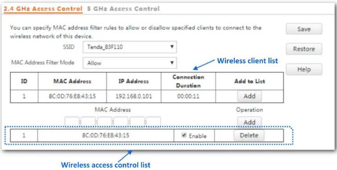
text_image
2.4 GHz Access Control 5 GHz Access Control You can specify MAC address filter rules to allow or disallow specified clients to connect to the wireless network of this device. SSID Tenda_83F110 MAC Address Filter Mode Allow Wireless client list ID MAC Address IP Address Connection Duration Add to List 1 8C:0D:76:E8:43:15 192.168.0.101 00:00:11 Add MAC Address Operation Add 1 8C:0D:76:E8:43:15 Enable Delete Wireless access control listParameter descripon
| Parameter | Descripon |
| SSID | It species the wireless network to which the rule applies. |
| MAC Filter Mode | It species the Iter mode of the rule.Disable: It indicates that the access control funcon is disabled.Allow: It indicates that only the wireless clients on the access control list can connect to the AP with the selected SSID.Disallow: It indicates that only the wireless clients on the access control list cannot connect to the AP with the selected SSID. |
7.5.3 Example of Conguring Access Control
Networking requirement
A wireless network whose SSID is Home has been set up in a large apartment. Only family members are allowed to connect to the wireless network.
The Access Control funcon of the AP is recommended. The family members have three wireless devices whose MAC addresses are C8:3A:35:00:00:01, C8:3A:35:00:00:02, and C8:3A:35:00:00:03.
Conguraon procedure
Step 1 Choose Wireless Setng > Access Control > 5 GHz Access Control.
Step 2 Select Home from the SSID drop-down list.
Step 3 Select Allow from the MAC Filter Mode drop-down list.
Step 4 Enter C8:3A:35:00:00:01 in the MAC Address text box and click Add.
Step 5 Repeat step 4 to add C8:3A:35:00:00:02 and C8:3A:35:00:00:03 as well.
Step 6 Click Save.
---End
The following gure shows the conguraon.
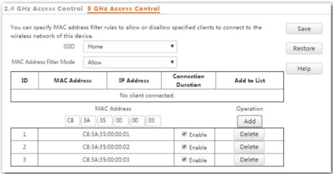
text_image
2.4 GHz Access Control 5 GHz Access Control You can specify MAC address filter rules to allow or disallow specified clients to connect to the wireless network of this device. SSID Home MAC Address Filter Mode Allow ID MAC Address IP Address Connection Duration Add to List No client connected. MAC Address Operation C8 3A 35 00 00 03 Add 1 C8:3A:35:00:00:01 Enable Delete 2 C8:3A:35:00:00:02 Enable Delete 3 C8:3A:35:00:00:03 Enable DeleteVericaon
Only the specied wireless devices can connect to the Home wireless network.
7.6 Advanced Sengs
7.6.1 Overview
This module is used to set the Idenfy Client Type and Broadcast Packet Filter of the AP.
Idenfy Client Type
It species whether to identify operang system types of wireless clients connected to this device. Terminal types that the AP can identify include: Android, iOS, WPhone, Windows, Mac OS, and so on.
Broadcast Packet Filter
By default, this device forwards lots of invalid broadcast packets from wired networks, which may affect business data transfer. The broadcast packet lter funcon allows you to lter broadcast packets by types so that invalid packets are not forwarded. This reduces air interface resources usage and ensures more bandwidth for business data transfer.
7.6.2 Changing the Advanced Sengs

It is recommended that you change the sengs only under the instrucon of professional personnel, so as to prevent decreasing the wireless performance of the AP.
Step 1 Choose Wireless Setng > Advanced Setngs.
Step 2 Change the parameter sengs as required.
Step 3 Click Save.
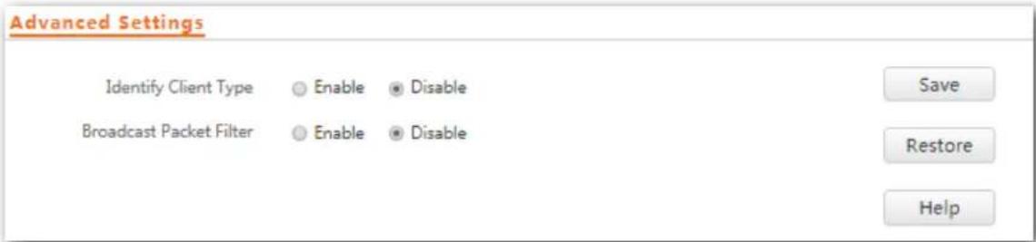
text_image
Advanced Settings Identify Client Type Enable Disable Broadcast Packet Filter Enable Disable Save Restore Help---End
Parameter descripon
| Parameter | Descripon |
| Ideny Client Type | Enable: It species whether to enable the funcon. The operang system type of wireless devices connected to the AP's WiFi network can be viewed by choosing Status > Wireless Clients.Disable: It species whether to disable the funcon. |
| Broadcast Packet Filter | Enable: It species whether to enable the funcon. With the funcon enabled, the AP can reduce air interface resources usage and ensure the bandwidth for business data transfer.Disable: It species whether to disable the funcon. |
| Filter Mode | Select a mode aer you enable the broadcast packet Iter funcon.Accept only DHCP and ARP packets: Filter out all broadcast or mulcast data except DHCP and ARP packets.Accept only ARP packets: Filter out all broadcast or mulcast data except ARP packets. |
7.7 QVLAN Sengs
7.7.1 Overview
The AP supports 802.1Q VLANs and is applicable in a network environment where 802.1Q VLANs have been dened. By default, the QVLAN funcon is disabled.
7.7.2 Conguring the QVLAN Funcon
Step 1 Choose Wireless Setng > QVLAN Sengs.
Step 2 Change the parameters as required. Generally, you only need to change the Enable, LAN Port, 2.4 GHz SSID VLAN ID and 5 GHz SSID VLAN ID sengs.
Step 3 Click Save.
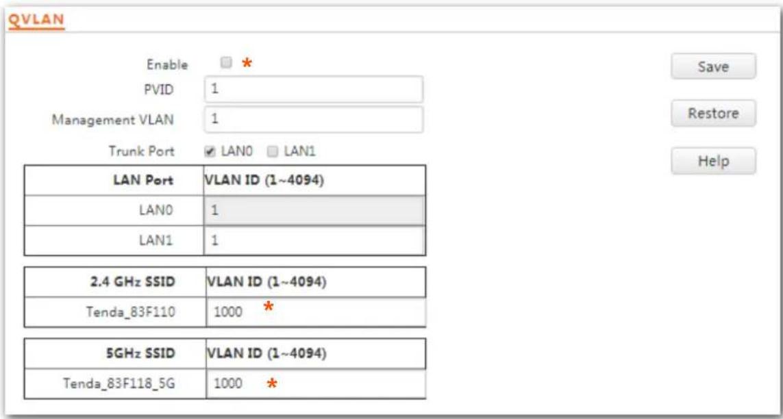
text_image
QVLAN Enable PVID 1 Management VLAN 1 Trunk Port ✓ LAN0 □ LAN1 LAN Port VLAN ID (1~4094) LAN0 1 LAN1 1 2.4 GHz SSID VLAN ID (1~4094) Tenda_83F110 1000 * 5GHz SSID VLAN ID (1~4094) Tenda_83F118_5G 1000 *---End
Parameter descripon
| Parameter | Descripon |
| Enable | It species whether to enable the QVLAN funcon of the AP. By default, it is disabled. |
| PVID | It species the ID of the default nave VLAN of the trunk port of the AP. The default value is 1. |
| Management VLAN | It species the ID of the AP management VLAN. The default value is 1.Aer changing the management VLAN, you can manage the AP only aer connecng your computer or AP controller to the new management VLAN. |
| Trunk Port | It species the LAN port used as a trunk port of the AP. The default value is LAN0.Trac of all VLANs can pass through a trunk port.NOTEIf the QVLAN funcon is enabled, at least one LAN port needs to be set as a trunk port.LAN0 indicates the LAN port at the rear of the AP (PoE power supply, data transmission mulplexing port), whereas LAN1 indicates the LAN port (data transmission port) at the front of the AP. |
| LAN Port | It species the LAN ports of the AP, including LAN0 and LAN1. |
| VLAN ID | It species the VLAN ID corresponding to a LAN port used as an access port. The default value is 1. |
| 2.4 GHz SSID | It species the currently enabled SSIDs of the AP at 2.4 GHz band. |
| 5 GHz SSID | It species the currently enabled SSIDs of the AP at 5 GHz band. |
| VLAN ID | It species VLAN IDs corresponding to SSIDs. The default value is 1000. Aer the QVLAN funcon is enabled, the wireless ports corresponding to SSIDs funcons as access ports. The PVID and VLAN ID of an access port are the same. |
If the QVLAN funcon is enabled, tagged data received by a port of the AP is forwarded to the other ports of the VLAN corresponding to the VID in the data, whereas untagged data received by a port of the AP is forwarded to the other ports of the VLAN corresponding to the PVID of the port that receives the data.
The following table describes how ports of dierent link types process transmied and received data.
| Port | Method to Process Received Data | Method to Process Transmied Data | |
| Tagged Data | Untagged Data | ||
| Access | Transmit data aer removing tags from the data. | ||
| Trunk | Forward the data to other ports of the VLAN corresponding to the VID in the data. | Forward the data to the other ports of the VLAN corresponding to the PVID of the port that receives the data | If the VID and PVID of a port are the same, transmit data aer removing tags from the data.If the VID and PVID of a port are dierent, transmit data without removing tags from the data. |
7.7.3 Example of Conguring QVLAN Sengs
Networking requirement
A hotel has the following wireless network coverage requirements:
- Guests are connected to VLAN 2 and can access only the internet. Staffs are connected to VLAN 3 and can access only the LAN.
- Managers are connected to VLAN4 and can access both the LAN and the internet.
Networking assumpon
- Set the SSID to internet for guests, oa for stas, and VIP for managers for 2.4 GHz network.
- The wireless networks with the aforementioned SSIDs are enabled and set on the AP.
Network topology
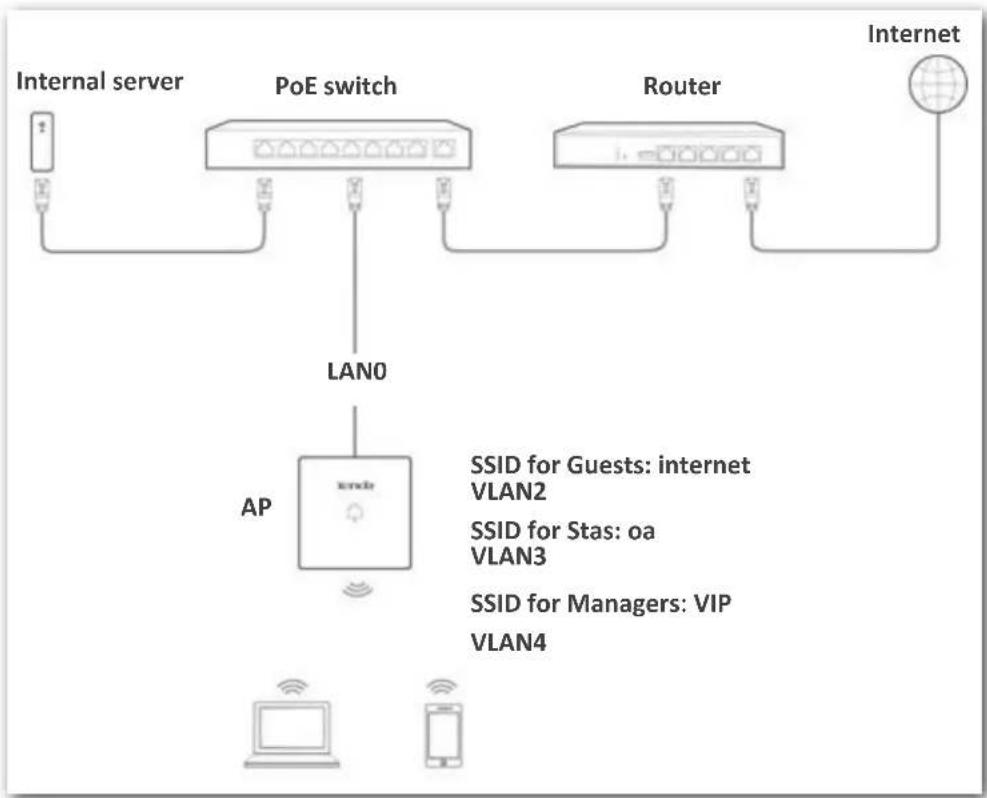
flowchart
graph TD
    A["Internal server"] --> B["PoE switch"]
    B --> C["LAN0"]
    C --> D["AP"]
    D --> E["Internet"]
    D --> F["AP"]
    style A fill:#f9f,stroke:#333
    style B fill:#ccf,stroke:#333
    style C fill:#cfc,stroke:#333
    style D fill:#fcc,stroke:#333
    style E fill:#cff,stroke:#333
    style F fill:#ffc,stroke:#333
Conguraon procedure
Congure the AP
Step 1 Log in to the web UI of the AP and choose Wireless Seng > QVLAN Sengs.
Step 2 Select the Enable check box.
Step 3 Modify the VLAN ID of the SSIDs at 2.4 GHz band. Set the VLAN of internet to 2, oa to 3, and VIP to 4 respectively.
Step 4 Click Save.
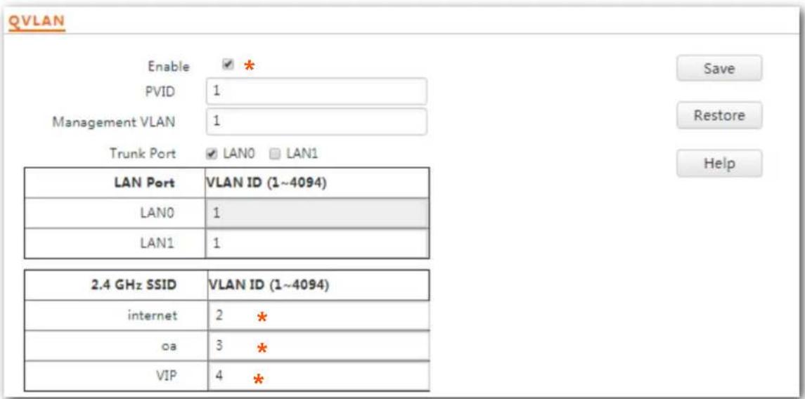
text_image
QVLAN Enable ✓ * PVID 1 Management VLAN 1 Trunk Port ✓ LAN0 □ LAN1 LAN Port VLAN ID (1~4094) LAN0 1 LAN1 1 2.4 GHz SSID VLAN ID (1~4094) internet 2 * oa 3 * VIP 4 *---End
Wait for the automac reboot of the AP.
Congure the switch
Create IEEE 802.1Q VLANs described in the following table on the switch.
| Port Connected To | Accessible VLAN ID | Port Type | PVID |
| AP | 1,2,3,4 | Trunk | 1 |
| LAN server | 3,4 | Trunk | 1 |
| Router | 2,4 | Trunk | 1 |
Retain the default sengs of other ports. For details, refer to the user guide for the switch.
--End
Vericaon
Wireless clients connected to the internet wireless network can only access the internet, wireless clients connected to the oa wireless network can only access the LAN. Wireless clients connected to the VIP wireless network can access both the internet and LAN.
8 SNMP
8.1 Overview
The Simple Network Management Protocol (SNMP) is the most widely used network management protocol in TCP/IP networks. SNMP enables you to remotely manage all your network devices compliant with this protocol, such as monitoring the network status, changing network device sengs, and receive network event alarms.
SNMP allows automac management of devices from various vendors regardless of physical dierences among the devices.
8.1.1 SNMP Management Framework
The SNMP management framework consists of SNMP manager, SNMP agent, and Management Information Base (MIB).
- SNMP manager: It is a system that controls and monitors network nodes using the SNMP protocol. The SNMP manager most widely used in network environments is Network Management System (NMS). An NMS can be a dedicated network management server, or an applicaon that implements management funcons in a network device.
– SNMP agent: It is a soware module in a managed device. The module is used to manage data about the device and report the management data to an SNMP manager. - MIB: It is a collecon of managed objects. It denes a series of aributes of managed objects, including names, access permissions, and data types of objects. Each SNMP agent has its MIB. An SNMP manager can read and/or write objects in the MIB based on the permissions assigned to the SNMP manager.
An SNMP manager manages SNMP agents in an SNMP network. The SNMP manager exchanges management informaon with the SNMP agents using the SNMP protocol.
8.1.2 Basic SNMP Operaons
The AP allows the following basic SNMP operaons:
- Get: An SNMP manager performs this operation to query the SNMP agent of the AP for values of one or more objects.
- Set: An SNMP manager performs this operation to set values of one or more objects in the MIB of the SNMP agent of the AP.
8.1.3 SNMP Protocol Version
The AP is compatible with SNMP V1 and SNMP V2C and adopts the community authencaon mechanism. Community name is used to denote the relationship between an SNMP agent and an SNMP manager. If the community name contained in an SNMP packet is rejected by a device, the packet is discarded. A community name funcons as a password to control SNMP agent access aempts of SNMP managers.
SNMP V2C is compatible with SNMP V1 and provides more funcons than SNMP V1. Compared with SNMP V1, SNMP V2C supports more operaons (GetBulk and InformRequest) and data types (such as Counter64), and provides more error codes for beer disguishing errors.
8.1.4 MIB Introducon
An MIB adopts a tree structure. The nodes of the tree indicate managed objects. A path consists of digits and stars from the root can be used to uniquely identify a node. This path is calling an object idener (OID). The following gure shows the structure of an MIB. In the gure, the OID of A is 1.3.6.1.2.1.1, whereas the OID of B is 1.3.6.1.2.1.2.
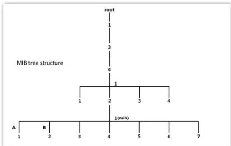
flowchart
graph TD
    root --> 1
    1 --> 3
    3 --> 6
    6 --> 1
    1 --> 2
    2 --> 3
    3 --> 4
    4 --> 1(mib)
    A --> 1
    B --> 2
    1 --> 3
    2 --> 4
    3 --> 5
    4 --> 6
    5 --> 7
8.2 Conguring the SNMP Funcon
Step 1 Choose SNMP and set SNMP Agent to Enable.
Step 2 Set related SNMP parameters.
Step 3 Click Save.
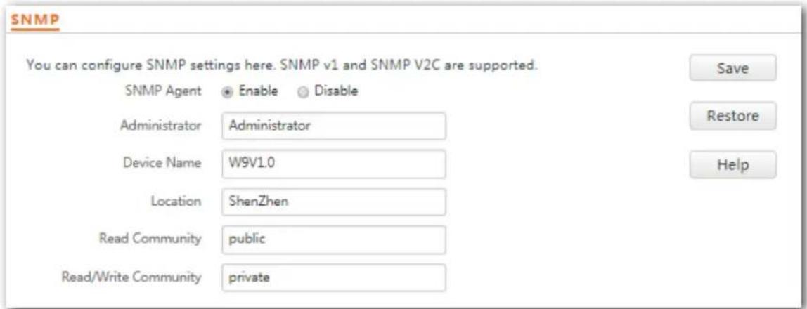
text_image
SNMP You can configure SNMP settings here. SNMP v1 and SNMP V2C are supported. SNMP Agent Enable Disable Administrator Administrator Device Name W9V1.0 Location ShenZhen Read Community public Read/Write Community private Save Restore Help---End
Parameter descripon
| Parameter | Descripon |
| SNMP Agent | It species whether to enable the SNMP agent funcon of the AP. By default, it is disabled.An SNMP manager and the SNMP agent can communicate with each other only if their SNMP versions are the same. Currently, the SNMP agent funcon of the AP supports SNMP V1 and SNMP V2C. |
| Administrator | It species the name of the administrator of the AP. The default name is Administrator. You can change the name as required. |
| Device Name | It species the device name of the AP. The default device name is the model of the AP.It is recommended that you change the AP name so that you can easily identify the AP when managing the AP using SNMP. |
| Locaon | It species the locaon where the AP is used. The default locaon is ShenZhen. You can change the locaon as required. |
| Read Community | It species the read password shared between SNMP managers and this SNMP agent. The default password is public.The SNMP agent funcon of the AP allows an SNMP manager to use the password to read variables in the MIB of the AP. |
| Read/Write Community | It species the read/write password shared between SNMP managers and this SNMP agent. The default password is private.The SNMP agent funcon of the AP allows an SNMP manager to use the password to read/write variables in the MIB of the AP. |
8.3 Example of Conguring the SNMP Funcon
Networking requirement
- The AP connects to an NMS over an LAN. This IP address of the AP is 192.168.0.254/24 and the IP address of the NMS is 192.168.0.212/24.
- The NMS use SNMP V1 or SNMP V2C to monitor and manage the AP.
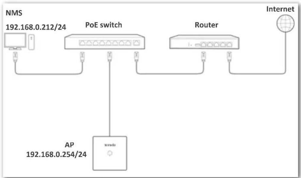
flowchart
graph TD
    A["NMS 192.168.0.212/24"] --> B["PoE switch"]
    B --> C["Router"]
    C --> D["Internet"]
    B --> E["AP 192.168.0.254/24"]
    E --> F["AP"]
Conguraon procedure
Conguring the AP
Assume that the administrator name is Tom, read community is Tom, and read/write community is Tom123.
Step 1 Log in to the web UI of the AP and choose SNMP.
Step 2 Set SNMP Agent to Enable.
Step 3 Set the SNMP parameters, Administrator, Device Name, Locaon, Read Community and Read/Write Community
Step 4 Click Save.
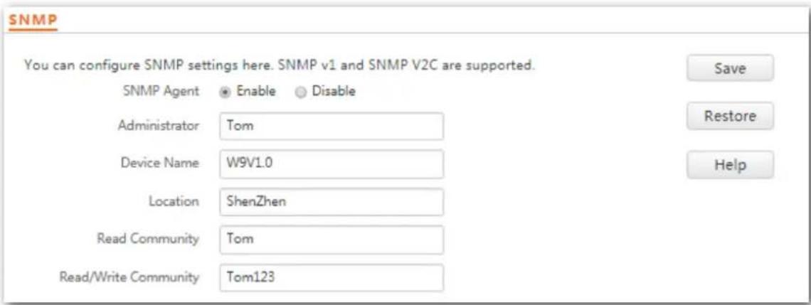
text_image
SNMP You can configure SNMP settings here. SNMP v1 and SNMP V2C are supported. SNMP Agent Enable Disable Administrator Tom Device Name W9V1.0 Location ShenZhen Read Community Tom Read/Write Community Tom123 Save Restore Help---End
Conguring the NMS
On an NMS that uses SNMP V1 or SNMP V2C, set the read community to Tom and read/write community to Tom 123. For details about how to conjure the NMS, refer to the conguraon guide for the NMS.
Vericaon
Aer the conguraon, the NMS can connect to the SNMP agent of the AP and query and set some parameters on the SNMP agent through the MIB.
9 Tools
9.1 Firmware Upgrade
This funcon upgrades the rmware of the AP for more funcons and higher stability.

To prevent damaging the AP, verify that the new rmware version is applicable to the AP before upgrading the rmware and keep the power supply of the AP connected during an upgrade.
Conguraon procedure:
Step 1 Download the package of a later rmware version for the AP from hp://www.Tenda.com.cn to your local computer, and decompress the package.
Step 2 Log in to the web UI of the AP and choose Tools > Firmware Upgrade.
Step 3 Click Choose File and select the le for upgrading the rmware.
Step 4 Click Upgrade.
Firmware Upgrade
You can upgrade the firmware of this device for more functions or more stable performance.
Select a Firmware File: Choose File No file chosen
Upgrade
Current Firmware Version: V1.0.0.5(1317); Release Date: 2017-11-28
Note: Do not power off this device when upgrade is in process. Otherwise, it may be damaged. When upgrade is complete, the device restarts automatically. The upgrade takes about 90 seconds. Please wait.
Step 5 Click OK.
192.168.0.254 says
Do you want to upgrade this device?
OK
Cancel
---End
Wait until the progress bar is complete. Log in to the web UI of the AP again. Choose Status > System Status and check whether the upgrade is successful based on Firmware Version.
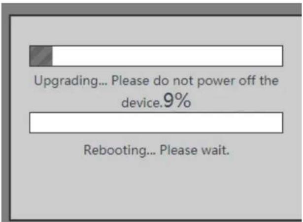
text_image
Upgrading... Please do not power off the device.9% Rebooting... Please wait.
Aer the rmware is upgraded, you are recommended to restore the factory sengs of the AP and congure the AP again, so as to ensure stability of the AP and proper operaon of new funcons.
9.2 Date & Time
This module enables you to set the system me and login meout interval of the AP.
9.2.1 System Time
Ensure that the system me of the AP is correct, so that logs can be recorded correctly and the reboot schedule can be executed correctly.
Log in to the web UI of the AP, choose Tools > Date & Time > System Time.
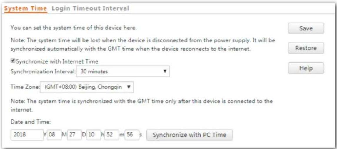
text_image
System Time Login Timeout Interval You can set the system time of this device here. Note: The system time will be lost when the device is disconnected from the power supply. It will be synchronized automatically with the GMT time when the device reconnects to the internet. ✓ Synchronize with Internet Time Synchronization Interval: 30 minutes Time Zone: (GMT+08:00) Beijing, Chongqin Note: The system time is synchronized with the GMT time only after this device is connected to the internet. Date and Time: 2018 Y 08 M 27 D 10 h 52 m 56 s Synchronize with PC TimeThe AP allows you to set the system me by synchronizing the me with the internet or manually seng the me. By default, it is congured to synchronize the system me with the internet.

No maer which method you use to conjure system me, when you log into the web UI of the AP, AP will automatically synchronize the me of the current management host.
Synchronizing with Internet Time
The AP automacally synchronizes its system me with a me server of the internet. This enables the AP to automacally correct its system me aer being connected to the internet.
For details about how to connect the AP to the internet, refer to LAN Setup.
Procedure for conging the AP to synchronize its system me with the internet:
Step 1 Choose Tools > Date & Time > System Time.
Step 2 Select Synchronize with Internet Time.
Step 3 Set Synchronizaon Interval to the interval at which the AP synchronizes its system me with a me server of the internet. The default value 30 minutes is recommended.
Step 4 Set Time Zone to the GMT standard me zone for the area where the AP is currently located.
Step 5 Click Save.
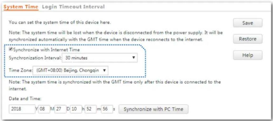
text_image
System Time Login Timeout Interval You can set the system time of this device here. Note: The system time will be lost when the device is disconnected from the power supply. It will be synchronized automatically with the GMT time when the device reconnects to the internet. ✓ Synchronize with Internet Time Synchronization Interval: 30 minutes Time Zone: (GMT+08:00) Beijing, Chongqin Note: The system time is synchronized with the GMT time only after this device is connected to the internet. Date and Time: 2018 Y 08 M 27 D 10 h 52 m 56 s Synchronize with PC Time---End
Seng Time and Date Manually
You can manually set the system me of the AP. If you choose this opon, you need to set the system me each me aer the AP reboots.
Conguraon procedure:
Step 1 Choose Tools > Date & Time > System Time.
Step 2 Enter a correct date and me, or click Synchronize with PC Time to synchronize the system me of the AP with the system me (ensure that it is correct) of the computer being used to manage the AP.
Step 3 Click Save.
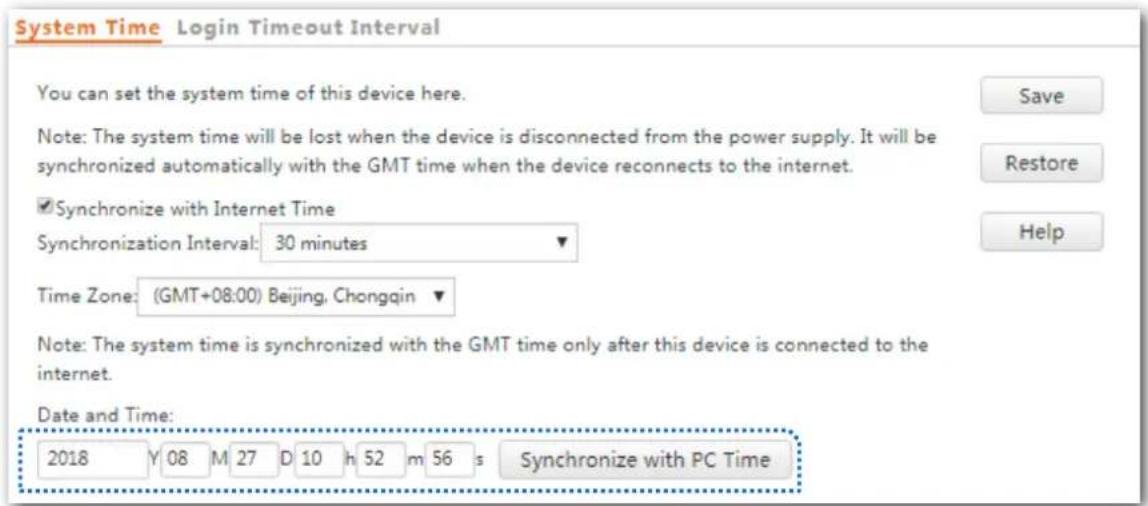
text_image
System Time Login Timeout Interval You can set the system time of this device here. Note: The system time will be lost when the device is disconnected from the power supply. It will be synchronized automatically with the GMT time when the device reconnects to the internet. ✓Synchronize with Internet Time Synchronization Interval: 30 minutes Time Zone: (GMT+08:00) Beijing, Chongqin Note: The system time is synchronized with the GMT time only after this device is connected to the internet. Date and Time: 2018 Y 08 M 27 D 10 h 52 m 56 s Synchronize with PC Time---End
9.2.2 Login Timeout Interval
If you log in to the web UI of the AP and perform no operaon within the login meout interval, the AP logs you out for network security. The default login meout interval is 5 minutes.
Procedure for seng the login meout interval:
- Choose Tools > Date & Time, and click Login Timeout Interval.
- Change the login meout interval as required.
- Click Save.
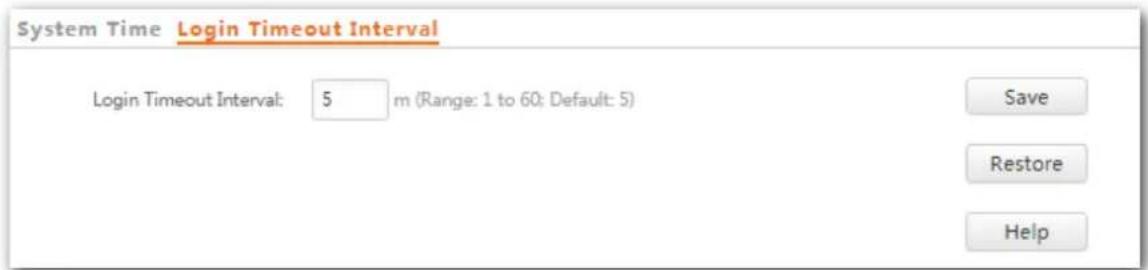
text_image
System Time Login Timeout Interval Login Timeout Interval: 5 m (Range: 1 to 60; Default: 5) Save Restore Help---End
9.3 Logs
This module enables you to view logs and congure log sengs.
9.3.1 Viewing Logs
The logs of the AP record various events that occur and the operaons that users perform aer the AP starts. In case of a system fault, you can refer to the logs during troublesomeong.
To access the page, choose Tools > Logs.

To ensure that the logs are recorded correctly, verify the system me of the AP. You can correct the system me of the AP by choosing Tools > Time & Date > System Time.
To view the latest logs of the AP, click Refresh. To clear the existing logs of the AP, click Clear.
NOTE
- When the AP reboots, the previous logs are lost.
- The AP reboots when the AP is powered on aer a power failure, the QVLAN funcon is congured, the rmware is upgraded, an AP conguraon is backed up or restored, or the factory sengs are restored.
9.3.2 Conguring Log Sengs
To access the page, choose Tools > Logs and click Log Sengs.
On this page, you can set the number of logs to be displayed and congure log servers.
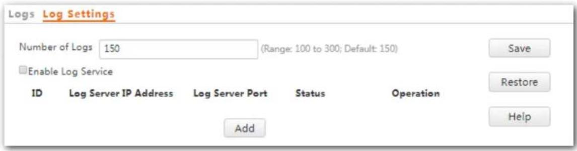
text_image
Logs Log Settings Number of Logs 150 (Range: 100 to 300; Default: 150) Enable Log Service ID Log Server IP Address Log Server Port Status Operation Add Save Restore HelpSeng the Number of Logs to Be Displayed
By default, the AP can display a maximum of 150 logs on the View Logs page. You can change the number as required.
Conguraon procedure:
Step 1 To access the page, choose Tools > Logs and click Log Sengs.
Step 2 Change the number of logs as required within the range of 100 to 300.
Step 3 Click Save.
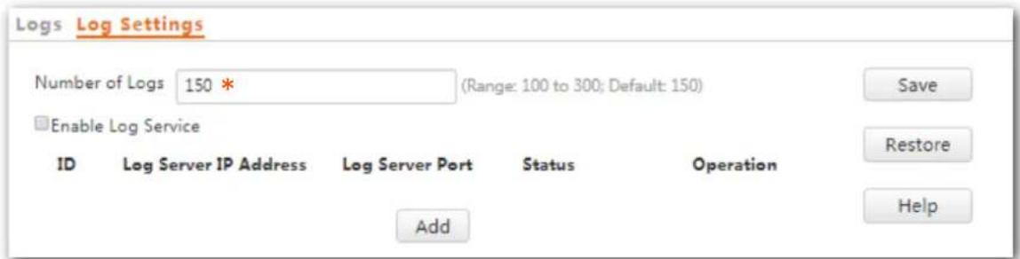
text_image
Logs Log Settings Number of Logs 150 * (Range: 100 to 300; Default: 150) Enable Log Service ID Log Server IP Address Log Server Port Status Operation Add Save Restore Help---End
Conguring Log Server Sengs
Aer you specify a log server, the AP sends its logs to the log server. You can view all the historical logs of the AP on the log server.

To ensure that system logs can be sent to a log server, choose Network Setngs > LAN Setup and set the IP address, subnet mask, and gateway of the AP for communicating with the log server.
Procedure for adding a log server
Step 1 To access the page, choose Tools > Logs and click Log Sengs.
Step 2 Click Add.
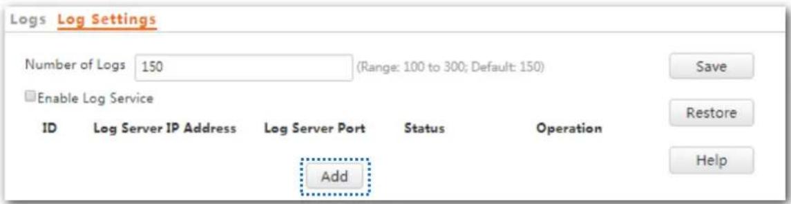
text_image
Logs Log Settings Number of Logs 150 (Range: 100 to 300; Default: 150) Enable Log Service ID Log Server IP Address Log Server Port Status Operation Add Save Restore HelpStep 3 Set parameters as follows:
Set Log Server IP Address to the IP address of the log server.
Set Log Server Port to the UDP port number used to send and receive system logs. The default port number 514 is recommended.
Select Enable to enable the log server.
Step 4 Click Save.
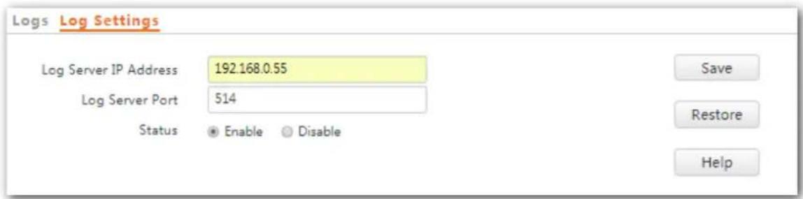
text_image
Logs Log Settings Log Server IP Address 192.168.0.55 Log Server Port 514 Status • Enable ○ Disable Save Restore Help---End
The following gure shows the conguraon.
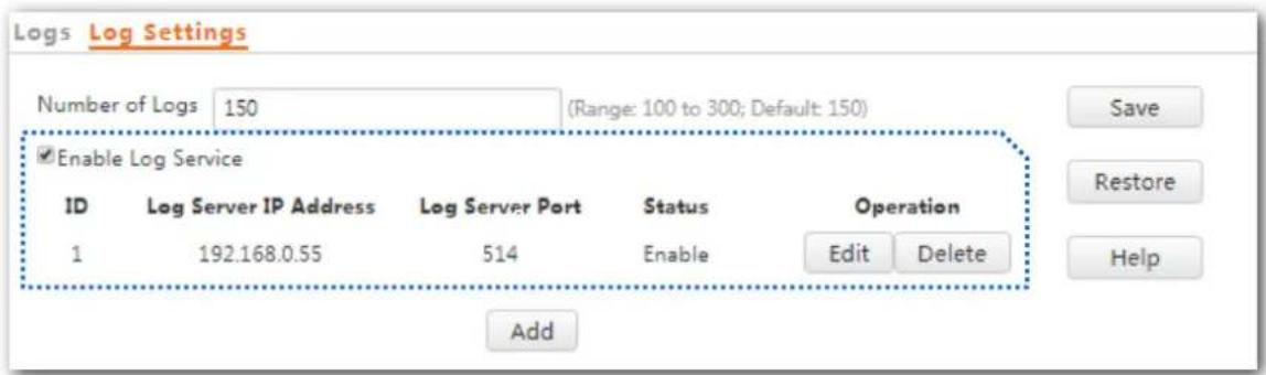
text_image
Logs Log Settings Number of Logs 150 (Range: 100 to 300; Default: 150) Enable Log Service ID Log Server IP Address Log Server Port Status Operation 1 192.168.0.55 514 Enable Edit Delete Add Save Restore HelpProcedure for changing log server sengs
Step 1 To access the page, choose Tools > Logs and click Log Settings.
Step 2 Click Edit corresponding to the log server sengs to be changed.
Step 3 Change the parameter sengs as required.
Step 4 Click Save.
---End
Procedure for deleng log server sengs
Step 1 To access the page, choose Tools > Logs and click Log Sengs.
Step 2 Click Delete corresponding to the log server sengs to be deleted.
Step 3 Click OK.
192.168.0.254 says
Do you want to delete the rule?
OK
Cancel
---End
9.4 Conguraon
This module enables you to back up the current conguraon of the AP, restore a conguraon of the AP, and restore the factory sengs of the AP.
9.4.1 Backing Up and Restoring Conguraons
The backup funcon enables you to back up the current conguraon of the AP to a local computer. The restoraon funcon enables you to restore the AP to a previous conguraon.
If the AP enters the opmum condion aer you greatly change the conguraon of the AP, you are recommended to back up the new conguraon, so that you can restore it aer upgrading or reseng the AP.

If you need to apply same or similar conguraons to many APs, you can conjure one of the APs, back up the conguraon of the AP, and use the backup to restore the conguraon on the other APs. This improves conguraon eciency.
Backing Up the Current Conguraon
Step 1 Choose Tools > Conguraon > Backup & Restore.
Step 2 Click Backup and follow the on-screen instrucons to perform operaons.
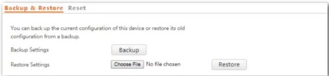
text_image
Backup & Restore Reset You can back up the current configuration of this device or restore its old configuration from a backup. Backup Settings Backup Restore Settings Choose File No file chosen RestoreStep 3 Click OK.
192.168.0.254 says
Please select a path to save the exported configuration file.
OK
Cancel
---End
A conguraon le named APCfm.cfg is downloaded.
Restoring a Conguraon
Step 1 Choose Tools > Conguraon > Backup & Restore.
Step 2 Click Choose File and select the le of the conguraon to be restored.
Step 3 Click Restore and follow the on-screen instrucons to perform operaons.
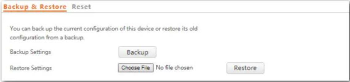
text_image
Backup & Restore Reset You can back up the current configuration of this device or restore its old configuration from a backup. Backup Settings Backup Restore Settings Choose File No file chosen RestoreStep 4 Click OK.
192.168.0.254 says
This device will restart after the configuration file is imported.
OK
Cancel
---End
The AP restores the conguraons successfully when the progress bar is done.
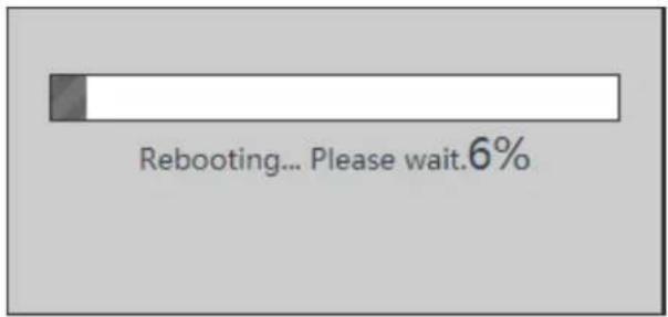
text_image
Rebooting... Please wait.6%9.4.2 Restoring the Factory Sengs
If you cannot locate a fault of the AP or forget the password of the web UI of the AP, you can reset the AP to restore its factory sengs and then congure it again.
NOTE
- When the factory sengs are restored, your conguraon is lost. Therefore, you need to reconfigure the AP to reconnect to the internet. Restore the factory sengs of the AP only when necessary.
• To prevent AP damages, ensure that the power supply of the AP is normal when the AP is reset. - Aer the factory sengs are restored, the login IP address of the AP is changed to 192.168.0.254, and the user name and password of the AP are changed to admin.
Method 1:
This method enables you to restore the factory sengs without logging in to the web UI of the AP.
Procedure: After the AP is powered on, use a pin to hold down the reset buon for 8 seconds and release it unl the green LED indicator turns solid on.
The AP is restored to factory sengs when the green LED indicator (SYS indicator) blinks again.
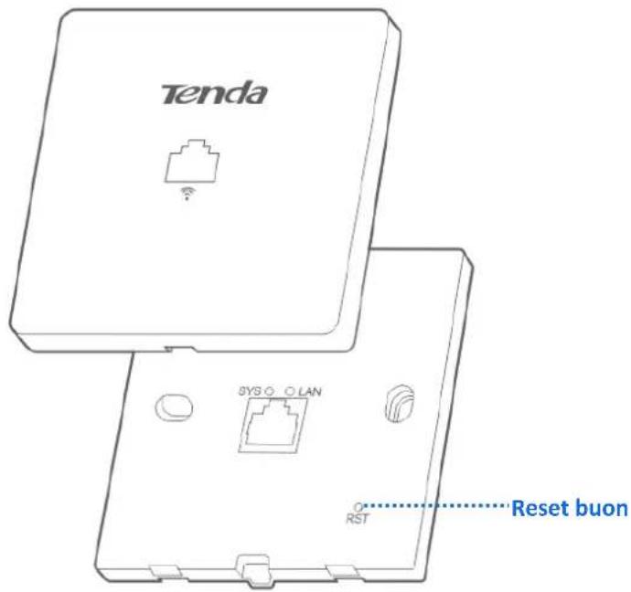
text_image
Tenda SYS O LAN RST Reset buonMethod 2:
Step 1 Log in to the web UI of the AP, choose Tools > Conguraon and click the Reset tab.
Step 2 Click the Reset buon.

text_image
Backup & Restore Reset If you click the Reset button, the factory settings of this device are restored. Reset HelpStep 3 Click OK.
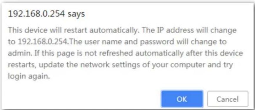
text_image
192.168.0.254 says This device will restart automatically. The IP address will change to 192.168.0.254.The user name and password will change to admin. If this page is not refreshed automatically after this device restarts, update the network settings of your computer and try login again. OK Cancel---End
Wait unl the progress bar is done.
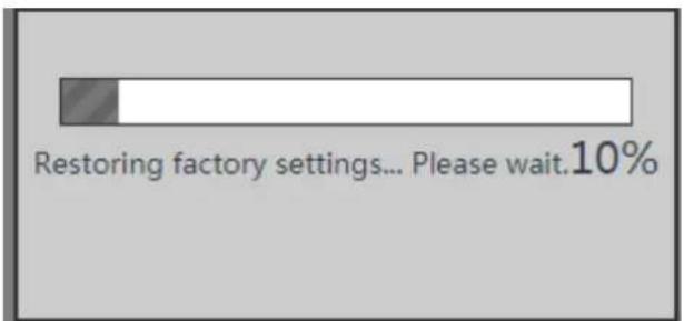
text_image
Restoring factory settings... Please wait.10%9.5 Account
To access page for changing user names and passwords, choose Tools > Account.
On this page, you can change the login account informaon of the AP to prevent unauthorized login.
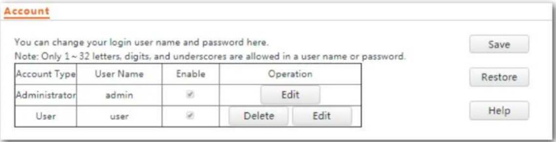
text_image
Account You can change your login user name and password here. Note: Only 1~32 letters, digits, and underscores are allowed in a user name or password. Account Type User Name Enable Operation Administrator admin Edit User user Delete Edit Save Restore HelpParameter descripon
| Parameter | Descripon |
| Account Type | Administrator: An account of this type enables you to view and modify sengs of the AP.User: An account of this type enables you to view sengs of the AP only. |
| User Name | It species the user name of an account.By default, the AP has one administrator account and one user account. Both the user name and password of the administrator account areadmin. Both the user name and password of the user account areuser. |
| Enable | It species whether an account is enabled.The administrator account is always enabled.The user account is enabled by default and can be disabled. |
| Operaon | Edit: This buon is used to modify the user name and password of the account corresponding to the buon.Delete: This buon is used to delete the user account.Add: This buon is used to add a user account aer the account is deleted.NOTEAer eding, deleng, or adding an account, clickSaveto apply the setngs. |
9.6 Diagnoscs Tool
If the network conncon fails, you can use the diagnoses tool included with the AP to locate the faulty node.
Procedure:
The link to www.google.com is used as an example.
Step 1 Choose Tools > Diagnoscs Tool.
Step 2 Enter the IP address or domain name to be pinged in the IP Address/Domain Name text box. In this example, enter www.google.com.
Step 3 Click Ping.
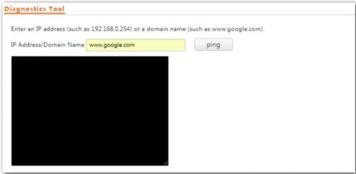
text_image
Diagnostics Tool Enter an IP address (such as 192.168.0.254) or a domain name (such as www.google.com). IP Address/Domain Name: www.google.com ping---End
The diagnosis result will be displayed in a few seconds in the black text box below the IP Address/Domain Name text box. See the following gure.
Diagnostics Tool
Enter an IP address (such as 192.168.0.254) or a domain name (such as www.google.com).
IP Address/Domain Name
www.google.com
ping
PING www.google.com (31.13.76.16): 56 data bytes
--- www.google.com ping statistics ---
3 packets transmitted, 0 packets received, 100% packet loss
9.7 Reboot Device
This module enables you to manually reboot the AP or congure the AP to automacally reboot.

When the AP reboots, all connecons are released. You are recommended to reboot the AP at an idle hour.
9.7.1 Manual Reboot
If a seng does not take eect or the AP works improperly, you can try reboong the AP manually to resolve the problem.
Procedure:
Step 1 To access the page, choose Tools > Reboot Device > Manual Reboot.
Step 2 Click Reboot.

text_image
Manual Reboot Reboot Schedule You can click the Reboot button to reboot this device immediately. RebootStep 3 Click OK.
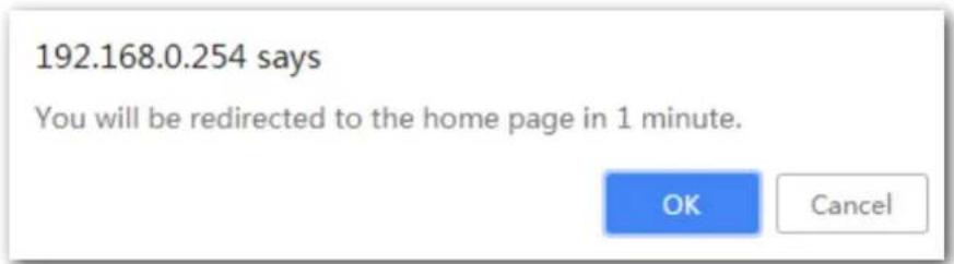
text_image
192.168.0.254 says You will be redirected to the home page in 1 minute. OK Cancel---End
Wait unl the progress bar is done.
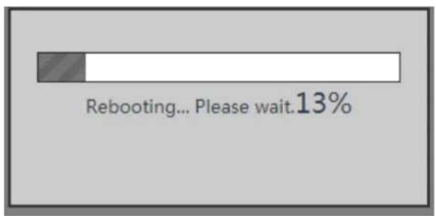
text_image
Rebooting... Please wait.13%9.7.2 Reboot Schedule
This funcon enables the AP to automacally reboot as scheduled. You can use this funcon to prevent wireless performance degradaon or network instability that occurs aer a long AP upme. The AP can reboot:
- At intervals: In this mode, the AP reboots at the interval that you specify.
- At specied me: In this mode, the AP reboots weekly at the me that you specify.
Conguring the AP to Reboot at Intervals
Step 1 Choose Tools > Reboot Device and click the Reboot Schedule tab.
Step 2 Select the Enable Reboot Schedule check box.
Step 3 Set Reboot Mode to At Intervals.
Step 4 Set Interval to a value in minutes, such as 1440.
Step 5 Click Save.
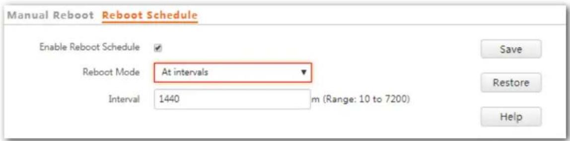
text_image
Manual Reboot Reboot Schedule Enable Reboot Schedule ✓ Reboot Mode At intervals ▼ Interval 1440 m (Range: 10 to 7200) Save Restore Help---End
Conguring the AP to Reboot at Specied Time
Step 1 Choose Tools > Reboot Device and click the Reboot Schedule tab.
Step 2 Select the Enable Reboot Schedule check box.
Step 3 Set Reboot Mode to At specied me.
Step 4 Select the day or days when the AP reboots, such as Monday - Friday
Step 5 Set the me when the AP reboots, such as 3:00.
Step 6 Click Save.

text_image
Manual Reboot Reboot Schedule Enable Reboot Schedule ✓ Reboot Mode At specified time ▼ Reboot On Every day Monday Tuesday Wednesday Thursday ✓ Friday Saturday Sunday Reboot At 3:00 Example: 3:00 Save Restore Help---End
9.8 LED Control
This funcon enables you to turn on/o the LED indicator of the AP. By default, the LED indicator is turned on.
Procedure for turning o the LED indicator:
Step 1 Choose Tools > LED Control.
Step 2 Click Disable all LEDs.

text_image
LED Control Disable All LEDs Help---End
Procedure for turning on the LED indicator:
Step 1 Choose Tools > LED Control.
Step 2 Click Enable All LEDs.

text_image
LED Control Enable All LEDs Help---End
9.9 Uplink Check
9.9.1 Overview
In AP mode, the AP connects to its upstream network using the LAN0 port. If a critical node between the LAN0 port and the upstream network fails, the AP as well as the wireless clients connected to the AP cannot access the upstream network. If uplink check is enabled, the AP regularly pings specied hosts through the LAN0 port. If all the hosts are not reachable, the AP stops its wireless service and wireless clients cannot nd the SSIDs of the AP. The client can reconnect to the AP only aer the conncon between the AP and the upstream networks is recovered.
If the uplink of the AP with uplink check enabled is faulty, wireless clients can connect to the upstream network through another nearby AP that works properly.
See the following topology (The LAN0 port serves as the uplink port).
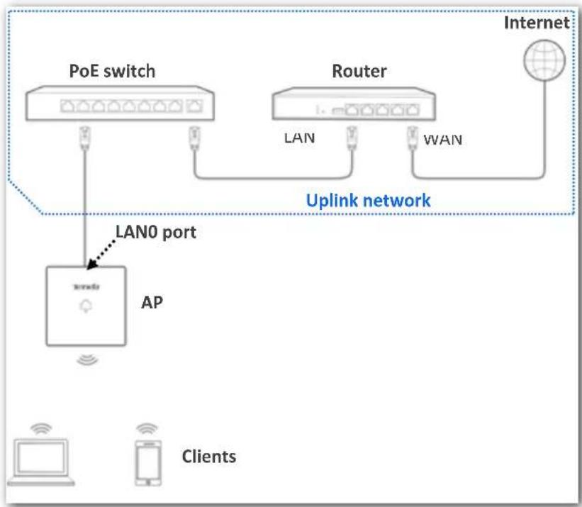
flowchart
graph TD
    A["PoE switch"] --> B["LAN0 port"]
    C["Router"] --> D["LAN"]
    C --> E["VWAN"]
    F["Internet"] --> G["AP"]
    H["Client"] --> I["AP"]
    style A fill:#f9f,stroke:#333
    style C fill:#f9f,stroke:#333
    style F fill:#ccf,stroke:#333
    style H fill:#cfc,stroke:#333
    style I fill:#fcc,stroke:#333
9.9.2 Conguring Uplink Check
Step 1 Choose Tools > Uplink Check.
Step 2 Select the Enable check box of Uplink Check.
Step 3 Set Host1 to Ping or Host2 to Ping to the IP address of the host to be pinged through the LAN0 port of the AP, such as the IP address of the switch or router directly connected to the AP.
Step 4 Set Ping Interval to the interval at which the AP checks its uplink.
Step 5 Click Save.
Uplink Check
Uplink Check
Enable
Host 1 to Ping

Host 2 to Ping

Ping Interval
10 m (Range: 10 to 100; Default: 10)
Save
Restore
Help
---End
Appendixes
A.1 FAQ
Q1: The LED indicators are o, what should I do?
A1. Try the following soluons:
- Verify the AP's rear port is connected to a PoE port (compliant with IEEE 802.3af) of the PoE switch properly.
– Ensure the Ethernet cable used to connect the AP and PoE switch is an eight-core Ethernet cable.
Q2: I cannot access the web UI of the AP. What should I do?
A2. Check the following items:
- Verify that the IP address of your computer is in the same segment as the AP's IP address. If the IP address of the AP is 192.168.0.254, the IP address of the computer should be set as 192.168.0.X (X: 2-253). Ensure the IP address of the AP (it is 192.168.0.254 by default) is entered in the browser address bar (not search bar).
- If two or more APs are connected to your network without a Tenda AP controller (including a router equipped with the AP controller funconality). Change the IP address of each AP during conguration to avoid IP conict. Otherwise, you can't access to the web UI of other APs. The AP may be being managed by an AP controller and therefore its IP address is no longer 192.168.0.254. In that case, log in to the web UI of the AP controller to view the new IP address of the AP, and log in to the AP using the new IP address.
If the problem persists, restore the factory sengs of the AP and try login again.
Q3 : How to reset the AP?
A3. Aer the AP is powered on, use a pin to hold down the reset buon for 8 seconds and release it until the green LED indicator turns solid on.
The AP is restored to factory sengs when the green LED indicator (SYS indicator) blinks again.
Q4: My wireless devices, such as smart phones, cannot access the internet via the AP aer conguraon. What should I do?
A4. Try the following soluons:
– Ensure that your wireless devices connect to the wireless network of the AP.
– Verify the router connected to the AP can access to the internet successfully.
A.2 Default Parameter Values
The following table lists the default parameter values of the AP.
| Parameter | Default Value | ||
| Login | Management IP address | 192.168.0.254 | |
| User Name/Password | Administrator | admin|admin | |
| User | user|user | ||
| Quick Setup | Working Mode | AP Mode | |
| LAN Setup | IP Address Type | Stac IP Address | |
| IP Address | 192.168.0.254 | ||
| Subnet Mask | 255.255.255.0 | ||
| Gateway | 192.168.0.1 | ||
| Primary DNS Server | 8.8.8.8 | ||
| Secondary DNS Server | 8.8.4.4 | ||
| Device Name | The model of the AP. For example, the default name of W9 V1.0 is W9V1.0. | ||
| DHCP Server | DHCP Server | Disable | |
| Start IP | 192.168.0.100 | ||
| End IP | 192.168.0.200 | ||
| Lease Time | 1 day | ||
| Subnet Mask | 255.255.255.0 | ||
| Gateway | 192.168.0.1 | ||
| Primary DNS Server | 8.8.8.8 | ||
| Secondary DNS Server | 8.8.4.4 | ||
| SSID Sengs | SSID | 2.4 GHz | The AP allows 8 SSIDs.The SSID displayed is Tenda_XXXXXX. Where XXXXXX indicates the range from the last 6 characters to the last 6 characters + 7 of the MAC address of the LAN ports of the AP.By default, the primary SSID is enabled, and the other SSIDs are disabled. |
| 5 GHz | The AP allows 4 SSIDs.The SSID displayed is Tenda_XXXXXX_5G. Where XXXXXX indicates the range from the last 6 characters + 8 to the last 6 characters +11 of the MAC address of the LAN ports of the AP.By default, the primary SSID is enabled, and the other SSIDs are disabled. | ||
| Broadcast SSID | Enable | ||
| Isolate Client | Disable | ||
| WMF | Enable | ||
| Suppress Broadcast Probe Response | Disable | ||
| Max. Number of Clients | 48 | ||
| Chinese SSID Encoding | UTF-8 | ||
| Security Mode | None | ||
| Radio Sengs | Enable wireless | Enable | |
| Country/Region | China | ||
| Network Mode | 2.4GHz 11b/g/n | ||
| 5GHz 11ac | |||
| Channel | Auto | ||
| Channel Bandwidth | 2.4GHz 20/40 MHz | ||
| 5GHz 80 MHz | |||
| Lock Channel | Enable | ||
| Lock Power | Enable | ||
| Preamble | Long Preamble | ||
| Short GI | Enable | ||
| Isolate SSID | Disable | ||
| Radio Opmizaon | Beacon Interval | 100 ms | |
| Fragment Threshold | 2346 | ||
| RTS Threshold | 2347 | ||
| Parameter | Default Value | ||
| DTIM Interval | 1 | ||
| Minimum RSSI Threshold | -90 dBm | ||
| Priorize 5GHz | Disable | ||
| Air Interface Scheduling | Disable | ||
| APSD | Disable | ||
| Client Timeout Interval | 5 minutes | ||
| Mandatory Rate | 2.4 GHz | 1, 2, 5.5, 11 | |
| 5 GHz | 6, 12, 24 | ||
| Oponal Rate | 2.4 GHz | 1, 2, 5.5, 6, 9, 11, 12, 18, 24, 36, 48, 54 | |
| 5 GHz | 6, 9, 12, 18, 24, 36, 48, 54 | ||
| WMM Sengs | WMM | Enable | |
| WMM Opmizaon Mode | Optimized for scenario with more than 10 users | ||
| Access Control | Disable | ||
| Advanced Sengs | Ideny Client Type | Disable | |
| Broadcast Packet Filter | Disable | ||
| QVLAN | Enabled | Disable | |
| PVID | 1 | ||
| Management VLAN | 1 | ||
| Trunk Port | LAN0 | ||
| LAN Port VLAN ID | 1 | ||
| 2.4 GHz SSID VLAN ID | 1000 | ||
| 5 GHz SSID VLAN ID | 1000 | ||
| SNMP | SNMP Agent | Disable | |
| Administrator | Administrator | ||
| Device Name | The model of the AP. For example, the default name of W9 V1.0 is W9V1.0. | ||
| Locaon | ShenZhen | ||
| Read Community | public | ||
| Read/Write Community | private | ||
| Time & Date | System Time | If Synchronize with Internet me is selected:Time Zone: (GMT+08:00) Beijing, Chongqing, Hong Kong,Urumqi, Taipei | |
| Login Timeout Interval | 5 minutes | ||
| Tools | Number of Logs Displayed | 150 | |
| Log server sengs | None | ||
| Reboot Schedule | Disable | ||
| LED Control | Enable all LEDs | ||
| Uplink Check | Disable | ||