
AS350 Panther - SSD Drive Apacer - Free user manual and instructions
Find the device manual for free AS350 Panther Apacer in PDF.


| Product Type | SSD (Solid State Drive) |
| Brand | Apacer |
| Model | AS350 Panther |
| Form Factor | 2.5 inch (7mm height) |
| Interface | SATA III (6.0 Gbps), backward compatible with SATA I/II |
| Capacity Options | 128GB, 256GB, 512GB, 1TB |
| NAND Flash Type | 3D TLC |
| Sequential Read Speed | Up to 560 MB/s |
| Sequential Write Speed | Up to 540 MB/s |
| Random Read (4K) | Up to 80,896 IOPS |
| Random Write (4K) | Up to 75,237 IOPS |
| MTBF | >1,500,000 hours |
| Endurance (TBW) | 75 TB (128GB), 180 TB (256GB), 425 TB (512GB), 835 TB (1TB) |
| Operating Temperature | 0°C to 70°C |
| Storage Temperature | -40°C to 70°C |
| Supply Voltage | 5V ±5% |
| Power Consumption (Active) | 1,260 mW (128GB) to 1,620 mW (1TB) |
| Power Consumption (Idle) | 320 mW (128GB/512GB/1TB), 325 mW (256GB) |
| Dimensions (L x W x H) | 100.00 x 69.85 x 6.90 mm |
| Weight | Approx. 60 g (estimate) |
| Connector | 7-pin SATA signal + 15-pin SATA power |
| Shock Resistance | 1,500 G (non-operating) |
| Vibration Resistance | 15 G (non-operating) |
| Flash Management Features | Global Wear Leveling, S.M.A.R.T., TRIM, Power Failure Management |
| Power Management | HIPM, DIPM, DevSleep (Device Sleep) |
| Certifications | CE, FCC, RoHS |
Frequently Asked Questions - AS350 Panther Apacer
User questions about AS350 Panther Apacer
0 question about this device. Answer the ones you know or ask your own.
Ask a new question about this device
Download the instructions for your SSD Drive in PDF format for free! Find your manual AS350 Panther - Apacer and take your electronic device back in hand. On this page are published all the documents necessary for the use of your device. AS350 Panther by Apacer.
USER MANUAL AS350 Panther Apacer
AS350 Product Specifications

text_image
PANTHER ApacheAug, 2018
Version 2.0
Apacer Technology Inc.
1F, No.32, Zhongcheng Rd., Tucheng Dist., New Taipei City, Taiwan, R.O.C
Tel: +886-2-2267-8000 Fax: +886-2-2267-2261
www.apacer.com
Specifications Overview:
• Compliance with SATA Revision 3.1
- SATA 6.0 Gbps interface
- Backward compatible with SATA 1.5 and 3.0 Gbps interfaces
- Capacity
- 128GB, 256GB, 512GB, 1TB
- Performance\*
- Sequential read: Up to 560 MB/sec
- Sequential write: Up to 540 MB/sec
– Random read (4K): Up to 80,896 IOPS
– Random write (4K): Up to 75,237 IOPS
- Flash Management
- Global Wear Leveling
- S.M.A.R.T.
– Power Failure Management - TRIM
• NAND Flash Type: 3D TLC
• MTBF: >1,500,000 hours
• Endurance (in Terabytes Written: TBW)
- 128 GB: 75 TBW
- 256 GB: 180 TBW
- 512 GB: 425 TBW
- 1 TB: 835 TBW
• Temperature Range
- Operating:
Standard: 0°C to 70°C - Storage: -40°C to 70°C
• Supply Voltage
- 5.0 V ± 5%
• Power Consumption\*
-
Active mode:
1,260 mW (128GB)
1,450 mW (256GB)
1,360 mW (512GB)
1,620 mW (1TB) -
Idle mode:
320 mW (128GB)
325 mW (256GB)
320 mW (512GB)
320 mW (1TB)
- Connector Type
- 7-pin SATA signal connector
- 15-pin SATA power connector
Form Factor
- 2.5"
- Dimensions with 7mm enclosure: 100.00 x 69.85 x 6.90, unit: mm
- Shock & Vibration\*\*
- Shock:1,500 G
- Vibration: 15 G
• SATA Power Management Modes
• RoHS Compliant
Apacer
Table of Contents
1.1 Introduction....3
1.2 Performance .... 3
1.3 Pin Assignments....4
2.1 Command Set 6
2.2 S.M.A.R.T. 6
3.1 Global Wear Leveling 8
3.2 Power Failure Management 8
3.3 TRIM 8
3.4 SATA Power Management 8
4.1 Environmental 9
4.2 Mean Time Between Failures (MTBF) 9
4.3 Certification and Compliance 9
4.4 Endurance....9
5.1 Operating Voltage 10
5.2 Power Consumption 10
6.1 7mm Type Dimensions....11
6.2 Part Number Listing 12
1. General Descriptions
1.1 Introduction
Apacer AS350 SSD (Solid State Drive) consists of semiconductor devices using 3D TLC NAND flash memory that provide excellent reliability and high performance for storage media. Apacer AS350 does not contain any moving parts such as platter (disk) and head media, and thus it makes the better storage solution with higher performance, reduced latencies and low power consumption for notebooks, tablets and industrial PCs. Apacer AS350 delivers all the advantages of flash memory technologies and is fully compliant with the Serial ATA I/II/III (SATA) interface and standard 2.5-inch storage drive form factor.
1.2 Performance
Performance of Apacer AS350 SSD is listed below in Table 1-2.
Table 1-1 Performance Specifications
| Performance | 128GB | 256GB | 512GB | 1TB |
| Sequential Read* (MB/s) | 560 | 560 | 560 | 560 |
| Sequential Write* (MB/s) | 540 | 540 | 540 | 540 |
| Random Read IOPS** (4K) | 65402 | 84850 | 75811 | 80896 |
| Random Write IOPS** (4K) | 81994 | 86060 | 68331 | 75237 |
Note:
Results may differ from various flash configurations or host system setting.
*Sequential performance was measured using ATTO with SATA 6Gbps host.
1.3 Pin Assignments
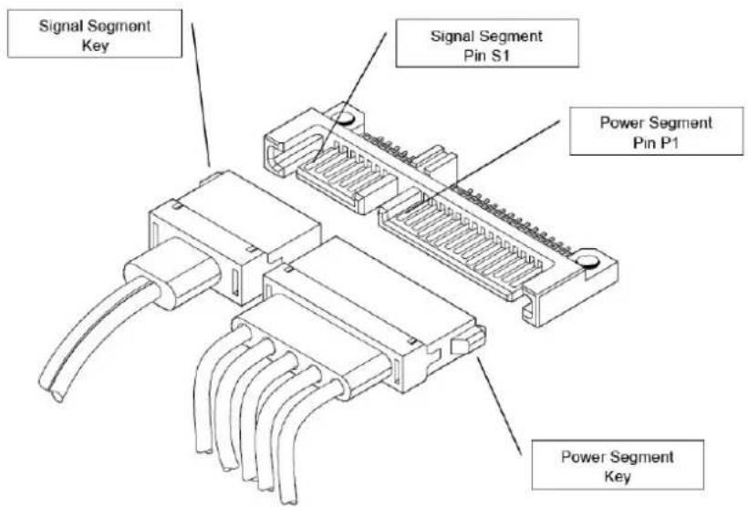
Table 1-2 describes the SFD signal segment, and Table1-3, power segment.
Figure 1-1 SATA Connectors
text_image
Signal Segment Key Signal Segment Pin S1 Power Segment Pin P1 Power Segment KeyTable 1-2 Signal Segment
| Pin | Type | Description |
| S1 | GND | |
| S2 | RxP | + Differential Receive Signal |
| S3 | RxDN | - Differential Receive Signal |
| S4 | GND | |
| S5 TxN | - Differential Transmit Signal | |
| S6 TxP | + Differential Transmit Signal | |
| S7 | GND | |
Table 1-3 Power Segment
| Pin Signal/Description | |
| P1 | Unused (3.3V) |
| P2 | Unused (3.3V) |
| P3 | Device Sleep |
| P4 | Ground |
| P5 | Ground |
| P6 | Ground |
| P7 | 5V |
| P8 | 5V |
| P9 | 5V |
| P10 | Ground |
| P11 | DAS |
| P12 | Ground |
| P13 | Unused (12V) |
| P14 | Unused (12V) |
| P15 | Unused (12V) |
Apacer
flowchart
graph LR
    subgraph_Host_Chip["Host Chip, PCB & Connector"]
        A1["Host Tx+"] --> B1["GND"]
        A2["Host Tx-"] --> B2["A+"]
        A3["Host Rx-"] --> B3["A-"]
        A4["Host Rx+"] --> B4["GND"]
        B1 --> C1["Key 1"]
        B2 --> C2["Key 2"]
        B3 --> C3["Key 3"]
        B4 --> C4["Key 4"]
        B5 --> C5["Key 5"]
        B6 --> C6["Key 6"]
        B7 --> C7["Key 7"]
    end

    subgraph Cable & Connectors["Cable & Connectors"]
        D1["Device Chip"] --> E1["Cable Receptacle"]
        D2["Device Chip"] --> E2["Cable Receptacle"]
        D3["Device Chip"] --> E3["Cable Receptacle"]
        D4["Device Chip"] --> E4["Cable Receptacle"]
        D5["Device Chip"] --> E5["Cable Receptacle"]
        D6["Device Chip"] --> E6["Cable Receptacle"]
        D7["Device Chip"] --> E7["Cable Receptacle"]
        D8["Device Chip"] --> E8["Cable Receptacle"]
        D9["Device Chip"] --> E9["Cable Receptacle"]
        D10["Device Chip"] --> E10["Cable Receptacle"]
        D11["Device Chip"] --> E11["Cable Receptacle"]
        D12["Device Chip"] --> E12["Cable Receptacle"]
    end

    subgraph_Device_Chip["Device Chip, PCB & Connector"]
        F1["Dev Rx+"] --> G1["GND"]
        F2["Dev Rx-"] --> G2["A+"]
        F3["Dev Tx-"] --> G3["A-"]
        F4["Dev Tx+"] --> G4["GND"]
        F5["Dev Tx-"] --> G5["B-"]
        F6["Dev Tx+"] --> G6["B+"]
        F7["Dev Tx+"] --> G7["GND"]
    end

    A1 --> B1
    A2 --> B2
    A3 --> B3
    A4 --> B4
    A5 --> B5
    A6 --> B6
    A7 --> B7
    A8 --> B8
    A9 --> B9
    A10 --> B10
    B1 --> C1
    B2 --> C2
    B3 --> C3
    B4 --> C4
    B5 --> C5
    B6 --> C6
    B7 --> C7
    B8 --> C8
    B9 --> C9
    B10 --> C10
    B11 --> C11
    B12 --> C12
    B13 --> C13
    B14 --> C14
    B15 --> C15
    B16 --> C16
    B17 --> C17
    B18 --> C18
    B19 --> C19
    B20 --> C20
    B21 --> C21
    B22 --> C22
    B23 --> C23
    B24 --> C24
    B25 --> C25
    B26 --> C26
    B27 --> C27
    B28 --> C28
    B29 --> C29
    B30 --> C30
    B31 --> C31
    B32 --> C32
    B33 --> C33
    B34 --> C34
    B35 --> C35
    B36 --> C36
    B37 --> C37
    B38 --> C38
    B39 --> C39
    B40 --> C40
    B41 --> C41
    B42 --> C42
    B43 --> C43
    B44 --> C44
    B45 --> C45
    B46 --> C46
    B47 --> C47
    B48 --> C48
    B49 --> C49
    B50 --> C50
    B51 --> C51
    B52 --> C52
    B53 --> C53
    B54 --> C54
    B55 --> C55
    B56 --> C56
    B57 --> C57
    B58 --> C58
    B59 --> C59
    B60 --> C60
    B61 --> C61
    B62 --> C62
    B63 --> C63
    B64 --> C64
    B65 --> C65
    B66 --> C66
    B67 --> C67
    B68 --> C68
    B69 --> C69
    B70 --> C70
    style HostChip fill:#f9f,stroke:#333,stroke-width:2px
    style Cable&Connectors fill:#ccf,stroke:#333,stroke-width:2px
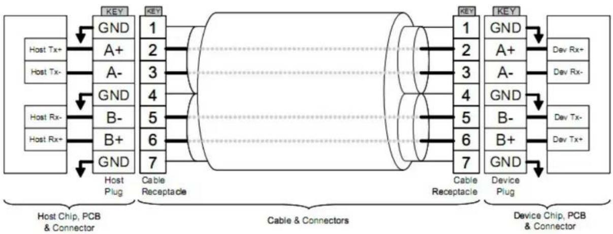
Figure 1-2 SATA Cable/Connector Connection Diagram
The connector on the left represents the Host with TX/RX differential pairs connected to a cable. The connector on the right shows the Device with TX/RX differential pairs also connected to the cable. Notice also the ground path connecting the shielding of the cable to the Cable Receptacle.
2. Software Interface
2.1 Command Set
Table 2-1 summarizes the ATA commands supported by Apacer AS350 SSD.
Table 2-1 Command Set
| Code | Command | Code | Command |
| E5h | Check Power Mode | F6h | Security Disable Password |
| 90h | Execute Diagnostics | F3h | Security Erase Prepare |
| E7h | Flush Cache | F4h | Security Erase Unit |
| ECh | Identify Device | F5h | Security Freeze Lock |
| E3h | Idle | F1h | Security Set Password |
| E1h | Idle Immediate | F2h | Security Unlock |
| 91h | Initialize Device Parameters | 7Xh | Seek |
| C8h | Read DMA | EFh | Set Features |
| 25h | Read DMA EXT | C6h | Set Multiple Mode |
| 60h | Read FPDMA Queued | E6h | Sleep |
| 47h | Read Log DMA EXT | B0h | S.M.A.R.T. |
| 2Fh | Read Log EXT | E2h | Standby |
| C4h | Read Multiple | E0h | Standby Immediate |
| 20 or 21h | Read Sector(s) | CAh | Write DMA |
| 40 or 41h | Read Verify Sector(s) | 35h | Write DMA EXT |
| 10h | Recalibrate | 61h | Write FPDMA Queued |
| 57h | Write Log DMA EXT | 3Fh | Write Log EXT |
| C5h | Write Multiple | 30h or 31h | Write Sector(s) |
2.2 S.M.A.R.T.
S.M.A.R.T. is an abbreviation for Self-Monitoring, Analysis and Reporting Technology, a self-monitoring system that provides indicators of drive health as well as potential disk problems. It serves as a warning for users from unscheduled downtime by monitoring and displaying critical drive information. Ideally, this should allow taking proactive actions to prevent drive failure and make use of S.M.A.R.T. information for future product development reference.
Apacer devices use the standard S.M.A.R.T. command B0h to read data out from the drive to activate our S.M.A.R.T. feature that complies with the ATA/ATAPI specifications. S.M.A.R.T. Attribute IDs shall include initial bad block count, total later bad block count, maximum erase count, average erase count, power on hours and power cycle. When the S.M.A.R.T. Utility running on the host, it analyzes and reports the disk status to the host before the device reaches in critical condition.
Apacer
Apacer memory products come with S.M.A.R.T. commands and subcommands for users to obtain information of drive status and to predict potential drive failures. Users can take advantage of the following commands/subcommands to monitor the health of the drive.
| Code | SMART Subcommand |
| D0h | READ DATA |
| D1h | READ ATTRIBUTE THRESHOLDS |
| D2h | Enable/Disable Attribute Autosave |
| D4h | Execute Off-line Immediate |
| D5h | Read Log (optional) |
| D6h | Write Log (optional) |
| D8h | Enable Operations |
| D9h | Disable operations |
| DAh | Return Status |
General SMART attribute structure
| Byte | Description |
| 0 | ID (Hex) |
| 1 – 2 | Status flag |
| 3 Value | |
| 4 Worst | |
| 5*-11 | Raw Data |
*Byte 5: LSB
SMART attribute ID list
| ID (Hex) | Attribute Name |
| 9 (0x09) | Power-on hours |
| 12 (0x0C) | Power cycle count |
| 163 (0xA3) | Max. erase count |
| 164 (0xA4) | Avg. erase count |
| 166 (0xA6) | Total later bad block count |
| 167 (0xA7) | SSD Protect Mode (vendor specific) |
| 168 (0xA8) | SATA PHY Error Count |
| 175 (0xAF) | Bad Cluster Table Count |
| 192 (0xC0) | Unexpected Power Loss Count |
| 194 (0xC2) | Temperature |
| 241 (0xF1) | Total sectors of write |
3. Flash Management
3.1 Global Wear Leveling
Flash memory devices differ from Hard Disk Drives (HDDs) in terms of how blocks are utilized. For HDDs, when a change is made to stored data, like erase or update, the controller mechanism on HDDs will perform overwrites on blocks. Unlike HDDs, flash blocks cannot be overwritten and each P/E cycle wears down the lifespan of blocks gradually. Repeatedly program/erase cycles performed on the same memory cells will eventually cause some blocks to age faster than others. This would bring flash storages to their end of service term sooner. Global wear leveling is an important mechanism that levels out the wearing of all blocks so that the wearing-down of all blocks can be almost evenly distributed. This will increase the lifespan of SSDs.
3.2 Power Failure Management
Power Failure Management plays a crucial role when experiencing unstable power supply. Power disruption may occur when users are storing data into the SSD. In this urgent situation, the controller would run multiple write-to-flash cycles to store the metadata for later block rebuilding. This urgent operation requires about several milliseconds to get it done. At the next power up, the firmware will perform a status tracking to retrieve the mapping table and resume previously programmed NAND blocks to check if there is any incompleteness of transmission.
Note: The controller unit of this product model is designed with a DRAM as a write cache for improved performance and data efficiency. Though unlikely to happen in most cases, the data cached in the volatile DRAM might be potentially affected if a sudden power loss takes place before the cached data is flushed into non-volatile NAND flash memory.
3.3 TRIM
TRIM is a SATA command that helps improve the read/write performance and efficiency of solid-state drives (SSD). The command enables the host operating system to inform SSD controller which blocks contain invalid data, mostly because of the erase commands from host. The invalid will be discarded permanently and the SSD will retain more space for itself.
3.4 SATA Power Management
Complying with SATA 6.0 Gb/s specifications, the SSD supports the following SATA power saving modes:
● ACTIVE: PHY ready, full power, Tx & Rx operational
● PARTIAL: Reduces power, resumes in under 10 μs (microseconds)
● SLUMBER: Reduces power, resumes in under 10 ms (milliseconds)
● HIPM: Host-Initiated Power Management
● DIPM: Device-Initiated Power Management
● AUTO-SLUMBER: Automatic transition from partial to slumber.
● Device Sleep (DevSleep or DEVSLP): PHY powered down; power consumption ≤ 5 mW; host assertion time ≤ 10 ms; exit timeout from this state ≤ 20 ms (unless specified otherwise in SATA Identify Device Log).
Note: The behaviors of power management features would depend on host/device settings.
4. Reliability Specifications
4.1 Environmental
Environmental specifications of Apacer AS350 SSD are shown in Table 5-1.
Table 5-1 Environmental Specifications
| Environment | Specifications |
| Temperature | 0°C to 70°C (Standard) |
| -40°C to 100°C (Non-operating) | |
| Vibration | Non-operating: Sine wave, 15(G), 10~2000(Hz), Operating: Random, 7.69(Grms), 20~2000(Hz) |
| Shock | Non-operating: Acceleration, 1,500 G, 0.5 ms Operating: Peak acceleration, 50 G, 11 ms |
4.2 Mean Time Between Failures (MTBF)
Mean Time Between Failures (MTBF) is predicted based on reliability data for the individual components in AS350. The prediction result for AS350 is more than 1,500,000 hours.
Note: The MTBF is predicated and calculated based on "Telcordia Technologies Special Report, SR-332, Issue 2" method.
4.3 Certification and Compliance
Apacer AS350 SSD complies with the following standards:
• CE
• FCC
- RoHS
4.4 Endurance
The endurance of a storage device is predicted by TeraBytes Written based on several factors related to usage, such as the amount of data written into the drive, block management conditions, and daily workload for the drive. Thus, key factors, such as Write Amplifications and the number of P/E cycles, can influence the lifespan of the drive.
Table 5-2 Endurance Specifications
| Capacity | TeraBytes Written |
| 128GB | 75 |
| 256GB | 180 |
| 512GB | 425 |
| 1TB | 835 |
Note:
- The measurement assumes the data written to the SSD for test is under a typical and constant rate.
• The measurement follows the standard metric: 1 TB (Terabyte) = 1,000 GB.
- The estimated values are based on JEDEC Enterprise endurance workload comprised of random data with the payload size distribution with sequential write behavior.
5. Electrical Specifications
5.1 Operating Voltage
Table 6-1 lists the supply voltage for AS350.
Table 6-1 Operating Range
| Item | Range |
| Supply Voltage | 5V ± 5% (4.75-5.25V) |
5.2 Power Consumption
Table 6-2 lists the power consumption for AS350.
Table 6-2 Power Consumption
| Mode | 128GB | 256GB | 512GB | 1TB |
| Active (mW) | 1260 | 1450 | 1360 | 1620 |
| Idle (mW) | 320 | 325 | 320 | 320 |
Note:
*All values are typical and may vary depending on flash configurations or host system settings.
**Active power is an average power measurement performed using CrystalDiskMark with 128KB sequential read/write transfers.
6. Physical Characteristics
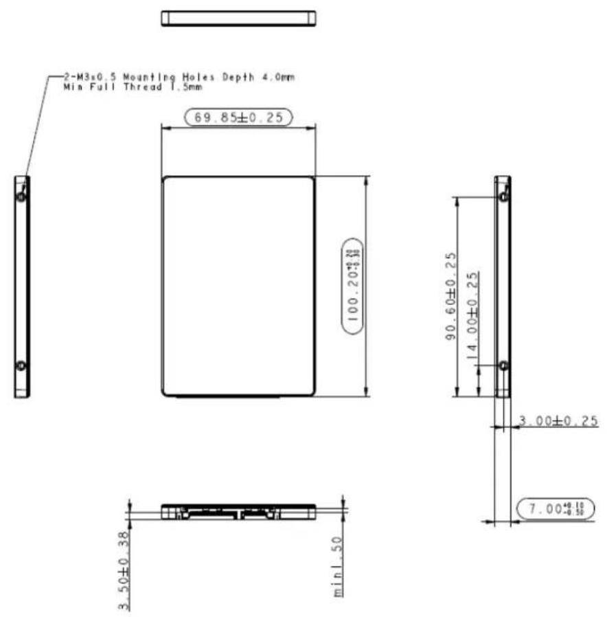
6.1 7mm Type Dimensions
text_image
2-M3x0.5 Mounting Holes Depth 4.0mm Min Full Thread 1.5mm 69.85±0.25 100.20±0.25 90.60±0.25 14.00±0.25 3.00±0.25 7.00±0.15 3.50±0.38 min 1.50Figure 7-1 7mm Housing Physical Dimensions
6.2 Part Number Listing
| Capacity | Retail PN | Bulk PN |
| 128GB | 95.DB260.P100C | 85.DB260.B100C |
| 256GB | 95.DB2A0.P100C 85.DB2A0.B100C | |
| 512GB | 95.DB2E0.P100C 85.DB2E0.B100C | |
| 1TB | 95.DB2G0.P100C 85.DB2G0.B100C |
Revision History
| Revision | Description | Date |
| 1.0 | Official release | 8/9/2018 |
| 2.0 | Document layout change | 8/20/2018 |
Global Presence
Taiwan (Headquarters)
Apacer Technology Inc.
1F., No.32, Zhongcheng Rd., Tucheng Dist.,
New Taipei City 236, Taiwan R.O.C.
Tel: 886-2-2267-8000
Fax: 886-2-2267-2261
amtsales@apacer.com
Japan
Apacer Technology Corp.
6F, Daiyontamachi Bldg., 2-17-12, Shibaura, Minato-Ku,
Tokyo, 108-0023, Japan
Tel: 81-3-5419-2668
Fax: 81-3-5419-0018
jpservices@apacer.com
China
Apacer Electronic (Shanghai) Co., Ltd
Room D, 22/FL, No.2, Lane 600, JieyunPlaza,
Tianshan RD, Shanghai, 200051, China
Tel: 86-21-6228-9939
Fax: 86-21-6228-9936
sales@apacer.com.cn
U.S.A.
Apacer Memory America, Inc.
46732 Lakeview Blvd., Fremont, CA 94538
Tel: 1-408-518-8699
Fax: 1-510-249-9551
sa@apacerus.com
Europe
Apacer Technology B.V.
Science Park Eindhoven 5051 5692 EB Son,
The Netherlands
Tel: 31-40-267-0000
Fax: 31-40-290-0686
sales@apacer.nl
India
Apacer Technologies Pvt Ltd,
Unit No.201, "Brigade Corner", 7 ^th Block
Jayanagar,
Yediyur Circle, Bangalore – 560082, India
Tel: 91-80-4152-9061
Fax: 91-80-4170-0215
sales_india@apacer.com