
Quinta Pro 55 - Chauffe-eau et ballon d'eau chaude Remeha - Free user manual and instructions
Find the device manual for free Quinta Pro 55 Remeha in PDF.


User questions about Quinta Pro 55 Remeha
0 question about this device. Answer the ones you know or ask your own.
Ask a new question about this device
Download the instructions for your Chauffe-eau et ballon d'eau chaude in PDF format for free! Find your manual Quinta Pro 55 - Remeha and take your electronic device back in hand. On this page are published all the documents necessary for the use of your device. Quinta Pro 55 by Remeha.
USER MANUAL Quinta Pro 55 Remeha
natural_image
Exterior view of a white rectangular appliance with a gray base and 'remeha' branding (no additional text or symbols visible)
Installation, User and Service Manual
High-efficiency wall-hung gas boiler
Quinta Pro
30 - 45 - 55 - 65 - 90 - 115
Dear Customer,
Thank you very much for buying this appliance.
Please read through the manual carefully before using the product, and keep it in a safe place for later reference. In order to ensure continued safe and efficient operation we recommend that the product is serviced regularly. Our service and customer service organisation can assist with this.
We hope you enjoy years of problem-free operation with the product.
Contents
1 Safety 6
1.1 General safety instructions 6
1.2 Recommendations 8
1.3 Liabilities 9
1.3.1 Manufacturer's liability 9
1.3.2 Installer's liability 10
1.3.3 User's liability 10
2 About this manual....11
2.1 Symbols used 11
2.1.1 Symbols used in the manual 11
2.2 Abbreviations 11
3 Technical specifications 12
3.1 Homologations 12
3.1.1 Certifications 12
3.1.2 Unit categories 12
3.1.3 Directives 12
3.1.4 Factory test 12
3.2 Technical data 12
3.3 Dimensions and connections 16
3.4 Electrical diagram 17
4 Description of the product 18
4.1 General description 18
4.2 Operating principle 18
4.2.1 Circulating pump 18
4.2.2 Cascade system 18
4.2.3 Water flow 18
4.2.4 Calorifier connection 19
4.3 Main components 19
4.4 Control panel description 19
4.4.1 What each key means 19
4.4.2 Meaning of the symbols on the display 20
4.5 Standard delivery 20
4.6 Accessories and options 20
5 Before installation 21
5.1 Installation regulations 21
5.2 Choice of the location 21
5.2.1 Type plate 21
5.2.2 Boiler position 21
5.3 Ventilation 21
6 Installation....22
6.1 General 22
6.2 Preparation 22
6.2.1 Positioning the boiler 22
6.3 Hydraulic connections 22
6.3.1 Rinsing the system 22
6.3.2 Connecting the heating circuit 23
6.3.3 Connecting the expansion vessel 24
6.3.4 Connecting the condensate discharge pipe .....24
6.4 Gas connection 24
6.5 Air supply/flue gas connections 24
6.5.1 Classification 24
6.5.2 Outlets 26
6.5.3 Material 26
6.5.4 Length of the air and flue gas pipes .....27
6.5.5 Additional guidelines 29
6.5.6 Connecting the flue gas outlet and air supply 29
6.6 Electrical connections 29
6.6.1 Control unit 29
6.6.2 Recommendations....30
6.6.3 Access to the connectors .....31
6.6.4 Connection options for the standard PCB 32
6.6.5 PCBs 37
6.7 Filling the installation 41
6.7.1 Water treatment 41
6.7.2 Filling the siphon 41
6.7.3 Filling the system 42
7 Commissioning 43
7.1 General 43
7.2 Gas circuit 43
7.3 Hydraulic circuit 43
7.4 Electrical connections 43
7.5 Commissioning procedure 43
7.6 Gas settings 44
7.6.1 Adjusting to a different gas type 44
7.6.2 Checking and setting the gas/air ratio 45
7.7 Final instructions 48
8 Operation....49
8.1 Use of the control panel 49
8.2 Shutdown 49
8.3 Frost protection 49
9 Settings....51
9.1 Parameter descriptions ..... 51
9.2 Changing the parameters 53
9.2.1 Changing the user-level parameters 54
9.2.2 Changing the parameters at installer level 54
9.2.3 Setting the maximum load for CH operation 55
9.2.4 Return to the factory settings .....57
9.2.5 Carrying out an auto-detect 57
9.2.6 Setting the manual mode .....58
9.3 Displaying the measured values 58
9.3.1 Reading the various current values 58
9.3.2 Reading out the hour counter and percentage of successful starts .....59
9.3.3 Status and sub-status 60
10 Maintenance 62
10.1 General 62
10.2 Maintenance message 62
10.2.1 Resetting the service messages 62
10.2.2 Starting a new service interval 63
10.3 Standard inspection and maintenance operations 63
10.3.1 Checking the water pressure 63
10.3.2 Checking the ionisation current 64
10.3.3 Checking the flue gas outlet/air supply connections 64
10.3.4 Checking the combustion 64
10.3.5 Checking the automatic air vent 65
10.3.6 Cleaning the siphon 65
10.3.7 Checking the burner and cleaning the heat exchanger 66
10.4 Specific maintenance work 67
10.4.1 Replacing the ionisation/ignition electrode 67
10.4.2 Checking the non-return valve 68
10.4.3 Reassembling the boiler 68
11 Troubleshooting....69
11.1 Error codes 69
11.1.1 Blocking 69
11.1.2 Lock out 71
11.2 Error memory 75
11.2.1 Reading out the error memory ....75
11.2.2 Clearing error memory 76
12 Disposal....77
12.1 Removal/recycling 77
13 Spare parts 78
13.1 General 78
13.2 Parts 79
14 Appendix....83
14.1 ErP information 83
14.1.1 Product fiche 83
14.1.2 Package sheet 84
14.2 EC declaration of conformity 85
14.3 Optional electrical connections 85
1 Safety
1.1 General safety instructions
For the installer:

Danger
If you smell gas:
- Do not use naked flames, do not smoke and do not operate electrical contacts or switches (doorbell, lighting, motor, lift etc).
- Shut off the gas supply.
- Open the windows.
- Trace possible leaks and seal them off immediately.
- If the leak is upstream of the gas meter, notify the gas company.

Danger
If you smell flue gases:
- Switch the boiler off.
- Open the windows.
- Trace possible leaks and seal them off immediately.

Caution
After maintenance or repair work, check the entire heating installation to ensure that there are no leaks.
For the end user:

Danger
If you smell gas:
- Do not use naked flames, do not smoke and do not operate electrical contacts or switches (doorbell, lighting, motor, lift etc).
- Shut off the gas supply.
- Open the windows.
- Report any leaks immediately.
- Evacuate the property.
- Contact a qualified installer.

Danger
If you smell flue gases:
- Switch the boiler off.
- Open the windows.
- Report any leaks immediately.
- Evacuate the property.
- Contact a qualified installer.

Warning
Do not touch the flue gas pipes. Depending on the boiler settings, the temperature of the flue gas pipes can rise to over 60^ C.

Warning
Do not touch radiators for long periods. Depending on the boiler settings, the temperature of the radiators can rise to over 60^ C.

Warning
The use of the boiler and the installation by you as the end-user must be limited to the operations described in this manual. All other actions may only be undertaken by a qualified fitter/engineer.

Caution
Ensure that the boiler is regularly serviced. Contact a qualified installer or arrange a maintenance contract for the servicing of the boiler.

Caution
Only genuine spare parts may be used.

Important
Regularly check for the presence of water and pressure in the heating installation.
1.2 Recommendations

Danger
This appliance can be used by children aged eight and above and people with a physical, sensory or mental disability, or with a lack of experience and knowledge, provided they are supervised and instructed in how to use the appliance in a safe manner and understand the associated dangers. Children must not be allowed to play with the appliance. Cleaning and user maintenance should not be carried out by children without adult supervision.

Warning
Installation and maintenance of the boiler must be carried out by a qualified installer in accordance with local and national regulations.

Warning
The installation and maintenance of the boiler must be undertaken by a qualified installer in accordance with the information in the supplied manual, doing otherwise may result in dangerous situations and/or bodily injury.

Warning
Removal and disposal of the boiler must be carried out by a qualified installer in accordance with local and national regulations.

Warning
If the mains lead is damaged, it must be replaced by the original manufacturer, the manufacturer's dealer or another suitably skilled person to prevent hazardous situations from arising.

Warning
Always disconnect the mains supply and close the main gas tap when working on the boiler.

Warning
Check the entire system for leaks after maintenance and servicing work.

Danger
For safety reasons, we recommend fitting smoke and CO alarms at suitable places in your home.

Caution
- Make sure the boiler can be reached at all times.
- The boiler must be installed in a frost-free area.
- If the power cord is permanently connected, you must always install a main bipolar switch with an opening gap of at least 3 mm (BS EN 60335-1).
- Drain the boiler and central heating system if you are not going to use your home for a long time and there is a chance of frost.
- The frost protection does not work if the boiler is out of operation.
- The boiler protection only protects the boiler, not the system.
- Check the water pressure in the system regularly. If the water pressure is lower than 0.8 bar, the system must be topped up (recommended water pressure between 1.5 and 2 bar).

Important
Keep this document near to the boiler.

Important
Only remove the casing for maintenance and repair operations. Refit all panels when maintenance work and servicing are complete.

Important
Instruction and warning labels must never be removed or covered and must be clearly legible throughout the entire service life of the boiler. Damaged or illegible instructions and warning stickers must be replaced immediately.

Important
Modifications to the boiler require the written approval of Remeha.
1.3 Liabilities
1.3.1 Manufacturer's liability
Our products are manufactured in compliance with the requirements of the various Directives applicable. They are therefore delivered with the C marking and any documents necessary. In the interests of the quality of our products, we strive constantly to improve them. We therefore reserve the right to modify the specifications given in this document.
Our liability as manufacturer may not be invoked in the following cases:
- Failure to abide by the instructions on installing the appliance.
- Failure to abide by the instructions on using the appliance.
- Faulty or insufficient maintenance of the appliance.
1.3.2 Installer's liability
The installer is responsible for the installation and initial commissioning of the appliance. The installer must observe the following instructions:
- Read and follow the instructions given in the manuals provided with the appliance.
• Install the appliance in compliance with prevailing legislation and standards. - Carry out initial commissioning and any checks necessary.
- Explain the installation to the user.
- If maintenance is necessary, warn the user of the obligation to check the appliance and keep it in good working order.
- Give all the instruction manuals to the user.
1.3.3 User's liability
To guarantee optimum operation of the system, you must abide by the following instructions:
- Read and follow the instructions given in the manuals provided with the appliance.
- Call on a qualified professional to carry out installation and initial commissioning.
- Get your installer to explain your installation to you.
- Have the required inspections and maintenance carried out by a qualified installer.
- Keep the instruction manuals in good condition close to the appliance.
2 About this manual
2.1 Symbols used
2.1.1 Symbols used in the manual
This manual uses various danger levels to draw attention to special instructions. We do this to improve user safety, to prevent problems and to guarantee correct operation of the appliance.

Danger
Risk of dangerous situations that may result in serious personal injury.

Danger of electric shock
Risk of electric shock.

Warning
Risk of dangerous situations that may result in minor personal injury.

Caution
Risk of material damage.

Important
Please note: important information.

See
Reference to other manuals or pages in this manual.
2.2 Abbreviations
PCU PCB for managing burner operation
PWM Pulse wide modulation
SCU Control panel PCB
SU Safety PCB
3 Technical specifications
3.1 Homologations
3.1.1 Certifications
Tab.1 Certifications
| CE identification number PIN | 0063CL3333 |
| NOx class 5 (EN 15502-1) | |
| Type of connection B | _23 , B_23P , B_33 |
| C_13 , C_33 , C_43 , C_53 , C_63 , C_83 , C_93 |
Tab.2 Gas Council number
| Quinta Pro 30 45 55 65 | ||||
| Gas Council num-ber | 41-288-15 4 | 1-288-16 41- | 228-18 41-28 | 8-17 |
3.1.2 Unit categories
Tab.3 Unit categories
| Country Category Gas type | Connection pressure (mbar) | ||
| Great Britain II | _2H3B/P _II_2H3P | G20 (H-gas)G31 (propane) | 2037-50 |
3.1.3 Directives
In addition to the legal requirements and guidelines, the supplementary guidelines in this manual must also be followed.
Supplements or subsequent regulations and guidelines that are valid at the time of installation shall apply to all regulations and guidelines specified in this manual.
3.1.4 Factory test
Before leaving the factory, each boiler is optimally set and tested for:
- Electrical safety.
- Adjustment of (O_2 / CO_2) .
- Water tightness.
- Gas tightness.
- Parameter setting.
3.2 Technical data
Tab.4 General
| Quinta Pro | 30 | 45 | 55 | 65 | 90 | 115 | ||
| Nominal output (Pn) | min-max | kW | 8.0 - 29.8 | 8.0 - 40.8 | 11.1 - | 12.0 - | 14.1 - | 20.5 - |
| Central heating operation (80°C/60°C) | ###^(1) | 29.8 | 40.8 | 55.3 | 61.5 | 84.2 | 107.0 | |
| 55.3 | 61.5 | 84.2 | 107.0 | |||||
| Quinta Pro 30 45 55 65 90 115 | ||||||||
| Nominal output (Pn)Central heating operation (50°C/30°C) | min-max [1] | kW 8.9 - | 31.431.4 | 8.9 - 43.043.0 | 12.3 -58.658.6 | 13.3 -65.065.0 | 15.8 -89.589.5 | 22.7 -114.0114.0 |
| Nominal input (Qn)Central heating operation (Hi) | min-max [1] | kW 8.2 - | 30.030.0 | 8.2 - 41.241.2 | 11.3 -56.556.5 | 12.2 -62.062.0 | 14.6 -86.086.0 | 19.6 -110.2110.2 |
| Nominal input (Qn)CH operation (Hi) G31 (propane) | min kW 8 | 8 8.8 12.2 | 12.2 22.1 | 21.2 | ||||
| Nominal input (Qn)Central heating operation (Hs) | min-max [1] | kW 9.1 - | 33.333.3 | 9.1 - 45.745.7 | 12.5 -62.762.7 | 13.6 -68.868.8 | 16.2 -95.595.5 | 21.9 -122.4122.4 |
| Full load central heating efficiency (Hi) (80/60°C) (92/42/EEC) | % 99.4 | 99.1 97.8 | 99.2 97.9 | 97.1 | ||||
| Full load central heating efficiency (Hi) (50°C/30°C) | % 102.9 | 102.9 10 | 3.8 104.6 | 104.1 102.5 | ||||
| Part load central heating efficiency (Hi) (return temperature 60°C) | % 97.5 | 97.5 97.9 | 98.3 96.6 | 96.5 | ||||
| Part load central heating efficiency (92/42/EEC) (return temperature 30°C) | % 110.4 | 110.6 10 | 8.7 110.4 | 108.1 108.0 | ||||
| (1) Factory setting | ||||||||
Tab.5 Gas and flue gas data
| Quinta Pro 30 45 55 65 90 115 | ||||||||
| Gas inlet pressure G20 (H gas) | min-max | mbar | 17 - 25 | 17 - 25 | 17 - 25 | 17 - 25 | 17 - 25 | 17 - 25 |
| Gas inlet pressure G31 (propane) | min-max | mbar | 37 - 50 | 37 - 50 | 37 - 50 | 37 - 50 | 37 - 50 | 37 - 50 |
| Gas consumption G20 (H gas)(1) | min.-max. | m^3/h | 0.9 - 3.2 | 0.9 - 4.4 | 1.2 - 6.0 | 1.3 - 6.6 | 1.5 - 9.1 | 2.0 - 11.7 |
| Gas consumption G31 (propane)(1) | min-max | m^3/h | 0.4 - 1.2 | 0.4 - 1.7 | 0.5 - 2.3 | 0.5 - 2.5 | 0.9 - 3.5 | 0.9 - 4.5 |
| Gas resistance G20 (H gas)(2) | max | mbar | 0.5 1.0 | 2.0 2.0 | 2.5 3.0 | |||
| BREAM NOx | mg/kW | h | 37 37 32 32 29 35 | |||||
| Flue gas quantity | min-max | kg/hg/s | 14 - 503.9 - 13.9 | 14 - 693.9 - 19.2 | 19 - 935.4 - 25.8 | 21 - 1045.8 - 28.9 | 28 - 1387.8 - 38.3 | 36 - 17810.0 -49.4 |
| Flue gas temperature | min-max | °C | 30 - 65 | 30 - 67 | 30 - 68 | 30 - 68 | 30 - 68 | 30 - 72 |
| Maximum counter pressure | Pa 70 150 120 100 160 220 | |||||||
| (1) Gas consumption based on lower heating value under standard conditions: T=288.15 K, p=1013.25 mbar. Gag 30.33; G25 29.25; G31 88.00 MJ/m3(2) Gas resistance between boiler connection and measurement point on the gas valve unit | ||||||||
Tab.6 Central heating circuit data
| Quinta Pro 30 45 55 65 90 115 | ||||||||
| Water content | I | 4.3 | 4.3 | 6.4 | 6.4 | 9.4 | 9.4 | |
| Water operating pressure | min | bar 0.8 | 0.8 0.8 0.8 0 | 8 0.8 | ||||
| Water operating pressure (PMS) | max | bar 4.0 | 4.0 4.0 4.0 4 | 0 4.0 | ||||
| Water temperature | max | °C | 110.0 | 110.0 | 110.0 | 110.0 | 110.0 | 110.0 |
| Operating temperature max °C 90 | 0 90.0 90 | 0 90.0 90 | 0 90.0 | |||||
| Hydraulic resistance (ΔT=20K) m | bar 70 90 | 130 140 | 140 250 |
Tab.7 Electrical data
| Quinta Pro 30 45 55 65 90 115 | ||||||||
| Supply voltage VAC 230 230 230 | 230 230 | 230 | ||||||
| Power consumption - full load max | W 39 68 | 80 88 125 | 199 | |||||
| Power consumption - part load max | W 18 18 | 23 23 20 | 45 | |||||
| Power consumption - standby | max | W | 5 | 5 | 6 | 6 | 4 | 7 |
| Electrical protection index(1) | IP | X4D(1) | X4D(1) | X4D(1) | X4D(1) | X4D(1) | X4D(1) | |
| Fuses | Main | A | 6.3 | 6.3 | 6.3 | 6.3 | 6.3 | 6.3 |
| PCU | 2.0 | 2.0 | 2.0 | 2.0 | 2.0 | 2.0 | ||
| (1) Splashproof; under certain conditions, the boiler may be installed in damp areas, such as bathrooms. | ||||||||
Tab.8 Other data
| Quinta Pro 30 45 55 65 90 115 | ||||||||
| Total weight (empty) | kg | 53 | 53 | 60 | 60 | 67 | 68 | |
| Minimum mounting weight ^(1) | kg | 49 | 49 | 56 | 56 | 65 | 65 | |
| Average acoustic level at a dis-tance of one metre from the boil-er | dB(A) | 38 | 45 | 45 | 45 | 52 | 51 | |
| (1) Without front panel. | ||||||||
Tab.9 Technical parameters
| Quinta Pro | 30 45 55 | 65 | 90 115 | |||||
| Condensing boiler | Yes | Yes | Yes | Yes | Yes | Yes | ||
| Low-temperature boiler^(1) | No | No | No | No | No | No | ||
| B1 boiler | No | No | No | No | No | No | ||
| Cogeneration space heater | No | No | No | No | No | No | ||
| Combination heater | No | No | No | No | No | No | ||
| Rated heat output | Prated | kW | 30 | 41 55 62 | 84 107 | |||
| Useful heat output at nominal heat output and high temperature operation^(2) | P_4 | kW 29.8 | 40.8 55.3 61 | .5 84.2 | 107.0 | |||
| Useful heat output at 30% of rated heat output and low temperature regime^(1) | P_1 | kW | 9.9 13.7 | 18.4 20.5 27 | 7.9 35.7 | |||
| Seasonal space heating energy efficiency | _s | % | 94 | 94 | 93 | 94 | - | - |
| Useful efficiency at rated heat output and high temperature regime^(2) | _4 | % | 89.5 89.3 | 88.1 89.4 | 88.2 87.5 | |||
| Useful efficiency at 30% of rated heat output and low temperature regime^(1) | _1 | % | 99.5 99.6 | 97.9 99.5 | 97.4 97.3 | |||
| Auxiliary electricity consumption | ||||||||
| Quinta Pro 30 45 55 65 90 115 | ||||||||
| Full load | elmax | kW 0.03 | 9 0.068 0.08 | 0 0.088 0.12 | 5 0.199 | |||
| Part load | elmin | kW 0.01 | 8 0.018 0.02 | 3 0.023 0.02 | 0 0.045 | |||
| Standby mode | P_SB | kW 0.00 | 5 0.005 0.00 | 6 0.006 0.00 | 4 0.007 | |||
| Other items | ||||||||
| Standby heat loss | P_stby | kW 0.10 | 1 0.101 0.11 | 0 0.110 0.12 | 3 0.123 | |||
| Ignition burner power con-sumption | P_ign | kW - - - - - | ||||||
| Annual energy consumption | Q_HE | GJ 91 124 171 187 - - | ||||||
| Sound power level, indoors | L_WA | dB 46 53 | 53 53 60 59 | |||||
| Emissions of nitrogen oxides NO x | mg/kW h | 32 33 29 | 29 41 41 | |||||
| (1) Low temperature means 30°C for condensing boilers, 37°C for low temperature boilers and 50°C (at heater inlet) for other heating appli-ances.(2) High temperature operation means 60°C return temperature at heater inlet and 80°C feed temperature at heater outlet. | ||||||||

See
The back cover for contact details.
3.3 Dimensions and connections
Fig.1 Dimensions
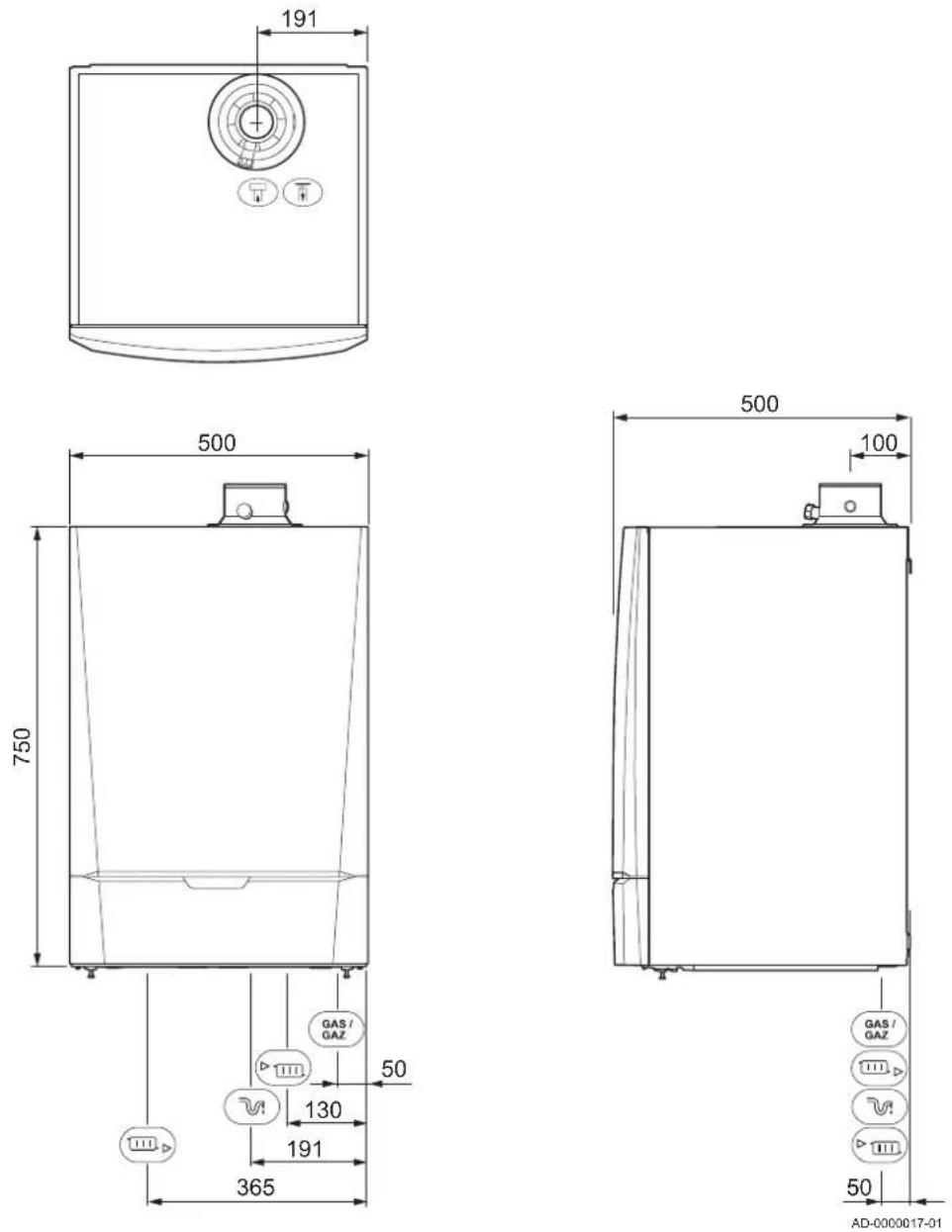
Tab.10 Connections
| Symbol | Connection Quinta Pro30 | Quinta Pro45 | Quinta Pro55 | Quinta Pro65 | Quinta Pro90 | Quinta Pro115 |
| Flue gas outlet 80 mm 80 m | m 100 mm | 100 mm 100 mm | 100 mm | |||
| Air supply 125 mm 125 mm | 150 mm 150 | mm 150 mm | 150 mm | |||
| Siphon 32 mm 32 mm 32 mm 32 mm 32 mm 32 mm 32 mm 32 mm 32 mm 32 mm 32 mm 32 mm 32 mm 32 mm 32 mm 32 mm 32 mm 32 mm 32 mm 32 mm 32 mm 32 mm 32 mm 32 mm 32 mm 32 | mm 32 mm 32 mm 32 mm 32 mm 32 mm 32 mm 32 mm 32 mm 32 mm 32 mm 32 mm 32 mm 32 mm 32 mm 32 mm 32 mm 32 mm 32 mm 32 mm 32 mm 32 mm 32 mm 32 mm 32 mm 32 ms | |||||
| ▶▶▶ | CH supply 1 1⁄4 inch male thread | 1 1⁄4 inch male thread | 1 1⁄4 inch male thread | 1 1⁄4 inch male thread | 1 1⁄4 inch male thread | 1 1⁄4 inch male thread |
| CH return 1 1⁄4 inch male thread | 1 1⁄4 inch male thread | 1 1⁄4 inch male thread | 1 1⁄4 inch male thread | 1 1⁄4 inch male thread | 1 1⁄4 inch male thread | |
| GAS/GAZ | Gas 3⁄4 inch male thread | 3⁄4 inch male thread | 3⁄4 inch male thread | 3⁄4 inch male thread | 3⁄4 inch male thread | 3⁄4 inch male thread |
3.4 Electrical diagram
Fig.2 Electrical diagram
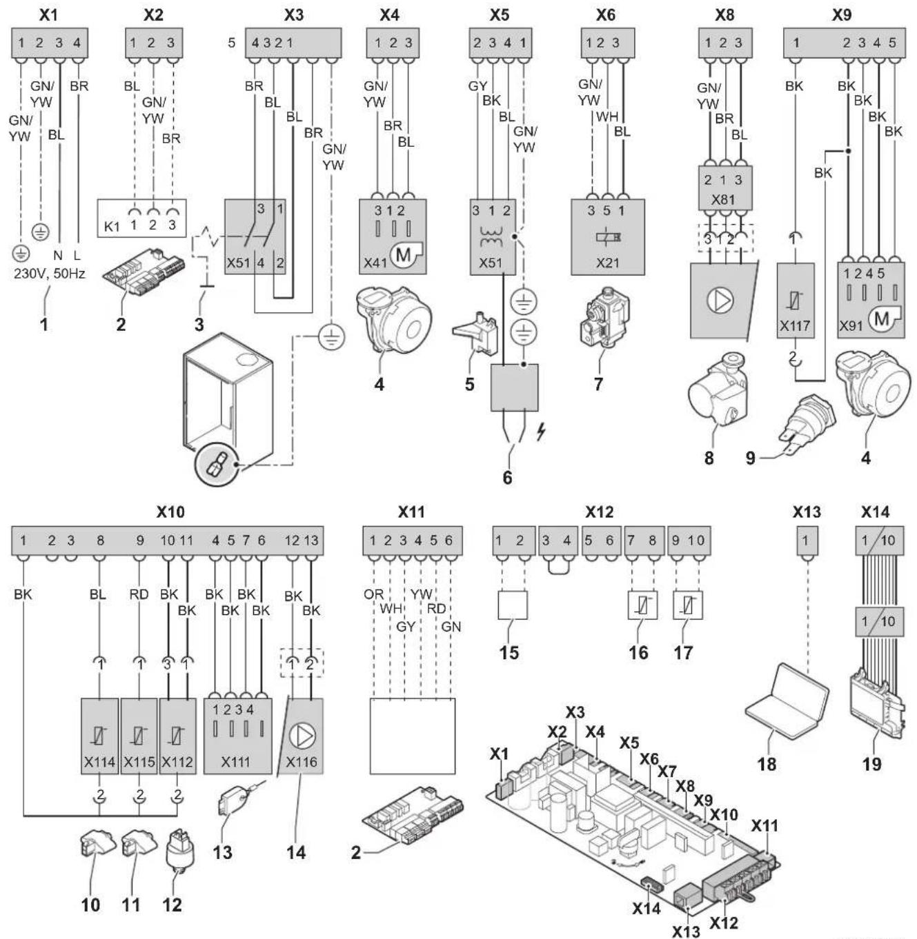
AD-0000062-01
1 Power supply (P)
2 Extended PCB (SCU)
3 On/off switch (S)
4 Fan (FAN)
5 Ignition transformer (IT)
6 Ignition pin (E)
7 Gas combination block (GB)
8 Circulating pump (pump A)
9 High limit switch (HLS)
10 Return sensor (RTS)
11 Flow sensor (FTS)
12 Pressure switch (PS)
13 Storage parameter (PSU)
14 Circulating pump (PWM pump)
15 Thermostat (OT)
16 Outside sensor (OS)
17 Calorifier sensor (WS)
18 Computer connection (PC)
19 Display (DIS)
BK Black
BL Blue
BR Brown
GN Green
GY Grey
RD Red
OR Orange
WH White
YW Yellow
4 Description of the product
4.1 General description
The Quinta Pro boiler has the following characteristics:
• High-efficiency heating.
- Limited emissions of polluted substances.
- Ideal choice for cascade configurations.
- Option to produce domestic hot water using a separate hot water appliance.
4.2 Operating principle
4.2.1 Circulating pump
■ Model not supplied with circulating pump
The boiler is supplied without a pump. Take the boiler resistance and system resistance into account when selecting a pump.

Caution
The pump may have a maximum input of 200 W. Use an auxiliary relay for a pump with greater power.

See
Technical data, page 12
If possible, install the pump directly under the boiler on the return connection.

For more information, see
Connecting the heating circuit, page 23
■ Pump settings
The pump settings for a modulating circulating pump controlled by the control unit can be modified using parameters P480: P29
- If there is insufficient flow in the radiators or if they do not warm up completely, the minimum pump speed can be increased using parameter P 28.
- If there are audible flowing noises in the system, the maximum pump speed must be lowered using parameter P2 Qbleed the CH installation first).

Caution
The pump may have a maximum input of 200 W. Use an auxiliary relay for a pump with greater power.

For more information, see
Changing the parameters at installer level, page 54
4.2.2 Cascade system
The boiler is ideally suited for a cascade system. There are a number of standard solutions available.

Important
Contact us for more information.
4.2.3 Water flow
The modulating control of the boiler limits the maximum temperature difference between the flow and return and the maximum rise velocity of the
flow temperature. As a result, the boiler is virtually unaffected by low water flow. In all cases, maintain a minimum water flow of 0.4 m^3/h . If progressive calorifier control is activated with parameter P then maintain a minimum water flow of 0.8 m^3/h .
4.2.4 Calorifier connection
A calorifier can be connected to the boiler. Our range includes various calorifiers.

Important
Contact us for more information.
4.3 Main components
Fig.3 Main components
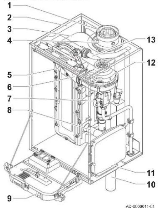
text_image
1 2 3 4 5 6 7 8 9 10 11 12 13 AD-0000011-011 Flue gas outlet/air supply
2 Casing/air box
3 Heat exchanger (CH)
4 Flue gas measuring point
5 Ionisation/ignition electrode
6 Mixer tube
7 Combined gas valve unit
8 Air intake silencer
9 Instrument box
10 Siphon
11 Housing for PCBs
12 Fan
13 Water flow pipe
4.4 Control panel description
Fig.4 Control panel
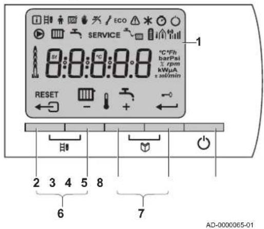
text_image
SERVICE 8:0:0:0:0.8 °C*Fh barPsi rpm kWμA ±sol/min RESET 2 3 4 5 8 6 7 AD-0000065-014.4.1 What each key means
1 Display
2 ← Escape or RESET
3 CH temperature or key
4 DHW temperature or key
5 ← Enter or Cancel key lockout
6 Chimney-sweeping keys
Press the 2 and 3 keys simultaneously.
7 Menu keys
Menu keys
Press the 4 and 5 keys simultaneously.
8 On/off switch
4.4.2 Meaning of the symbols on the display
Tab.11 Symbols on the display
| Information menu: Read out various current values. | |
| Chimney-sweeping position: Forced high or low load for O_2/CO_2 measurement. | |
| User menu: Parameters at user level can be changed. | |
| Central heating function off: The heating function is deactivated. | |
| Manual mode: Boiler is set to manual mode. | |
| DHW function off: The DHW function is switched off. | |
| Service menu: Parameters at installer level can be changed. | |
| ECO | ECO setting: The economy setting is activated. |
| Fault: Boiler indicates a fault. This can be seen from the Ecode and red display. | |
| Frost protection: Boiler is running in frost protection mode. | |
| Hour counter menu: Read out the operating hours, number of successful starts and hours on mains supply. | |
| On/off switch: After 5 lockouts, the boiler must be switched off/on again. | |
| Circulating pump: The pump is running. | |
| CH function: Access to CH temperature parameter. | |
| DHW function: Access to DHW temperature parameter. | |
| SERVICE | Yellow display with the symbols: f+ SE( maintenance message). R |
| Water pressure: The water pressure is too low. | |
| Battery symbol: Status of battery in wireless controller. | |
| Signal strength symbol: Signal strength of the wireless controller. | |
| Burner level: Boiler is running at full or part load. | |
| Key lockout: Key lockout is activated. |
4.5 Standard delivery
The delivery includes:
• The boiler, with mains lead
- Suspension bracket and fasteners for wall mounting
- Mounting template
- Connection cable for pump (Quinta Pro 30 - 45 - 55 - 65 - 90 - 115)
- Documentation
This manual only deals with the standard scope of supply. For the installation or mounting of any accessories delivered with the boiler, refer to the corresponding mounting instructions.
4.6 Accessories and options
Various accessories can be obtained for the boiler.

Important
Contact us for more information.
5 Before installation
5.1 Installation regulations

Warning
The installer must be registered with Gas Safe and have the correct ACS qualifications.

Important
Practical guidelines - see the latest version.
5.2 Choice of the location
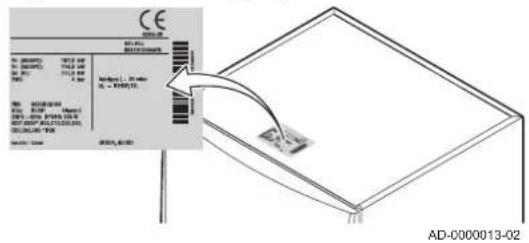
Fig.5 Position of type plate
text_image
CE H1.00 H2.00 H3.00 H4.00 H5.00 H6.00 H7.00 H8.00 H9.00 H10.00 H11.00 H12.00 H13.00 H14.00 H15.00 H16.00 H17.00 H18.00 H19.00 H20.00 H21.00 H22.00 H23.00 H24.00 H25.00 H26.00 H27.00 H28.00 H29.00 H30.00 H31.00 H32.00 H33.00 H34.00 H35.00 H36.00 H37.00 H38.00 H39.00 H40.00 H41.00 H42.00 H43.00 H44.00 H45.00 H46.00 H47.00 H48.00 H49.00 H50.00 H51.00 H52.00 H53.00 H54.00 H55.00 H56.00 H57.00 H58.00 H59.00 H60.00 H61.00 H62.00 H63.00 H64.00 H65.00 H66.00 H67.00 H68.00 H69.00 H70.00 H71.00 AD-0000013-025.2.1 Type plate
The type plate on top of the boiler features the boiler serial number and important boiler specifications, for example the model and unit category. The dF and dU codes are also stated on the type plate.
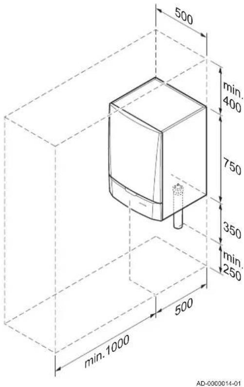
Fig.6 Installation area
text_image
500 min. 400 750 350 min. 250 500 min.1000 AD-0000014-015.2.2 Boiler position
- Use the guidelines and the required installation space as a basis for determining the correct place to install the boiler.
- When determining the correct installation space, take account of the permitted position of the flue gas discharge and/or air supply outlet.
- Ensure that there is sufficient space around the boiler for good access and ease of maintenance.

Danger
It is forbidden to store, even temporarily, combustible products and substances in the boiler or near the boiler.

Warning
- Fix the appliance to a solid wall capable of bearing the weight of the boiler when full of water and fully equipped.

Caution
• The boiler must be installed in a frost-free area.
• The boiler must have an earthed electrical connection.
- A connection to the drain must be present for the condensate drain close to the boiler.
5.3 Ventilation
The installation must comply with BS 5540 (part 1 + 2), BS 6644 and IGUP/10.
6 Installation
6.1 General

Warning
The boiler must be installed by a qualified installer in accordance with local and national regulations.
6.2 Preparation
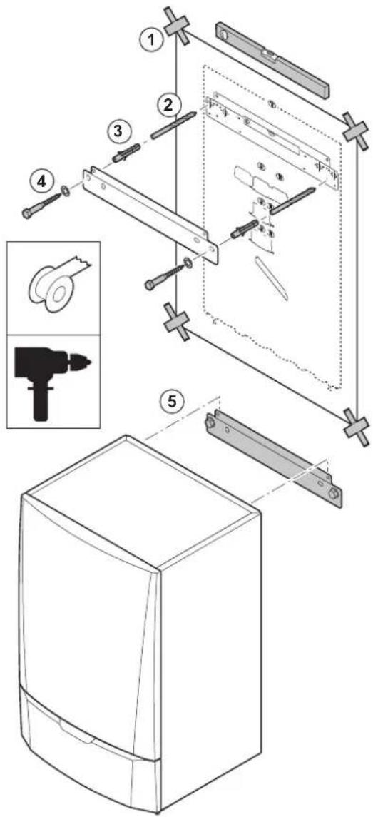
Fig.7 Mounting the boiler
text_image
Exploded view diagram of a refrigerator with numbered parts and exploded view, including a drill bit and power tool.AD-0000018-01
6.2.1 Positioning the boiler
The fitting bracket on the back of the casing can be used to mount the boiler directly on the suspension bracket.
The boiler is supplied with a mounting template.
- Attach the mounting template of the boiler to the wall using adhesive tape.

Warning
- Use a level to check whether the mounting template is hanging perfectly horizontally.
-
Protect the boiler against building dust and cover the connection points for the flue gas outlet and air supply. Only remove this cover to assemble the relevant connections.
-
Drill 2 holes of ∅ 10 mm.

Important
The extra holes are intended for use in the event that one of the two fastening holes is not suitable for correct fastening of the plug.
- Fit the ∅ 8 mm plugs.
- Attach the suspension bracket to the wall with the ∅ 10 mm bolts supplied.
- Mount the boiler on the suspension bracket.
6.3 Hydraulic connections
6.3.1 Rinsing the system
The installation must be cleaned and flushed in accordance with BS 7593 (2006) and BSRIA BG 33/2014.
Before a new CH boiler can be connected to an existing or new installation, the entire installation must be thoroughly cleaned and flushed. This
step is absolutely crucial. The flushing helps to remove residue from the installation process (weld slag, fixing products etc.) and accumulations of dirt (silt, mud etc.)

Important
Flush the CH installation with a volume of water equivalent to at least three times the volume of the CH installation. Flush the DHW pipes with at least 20 times the volume of the pipes.

Important
Due to the presence of an aluminium heat exchanger, suitable chemicals and the correct use of these chemicals should be discussed with specialist water treatment companies.
6.3.2 Connecting the heating circuit
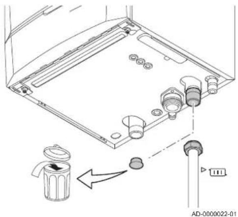
Fig.8 Connecting the CH flow
natural_image
Technical line drawing of a mechanical assembly with labeled components and directional arrows (no text or symbols)-
Remove the dust cap from the CH flow connection at the bottom of the boiler.
-
Fit the outlet pipe for CH water to the CH flow connection.
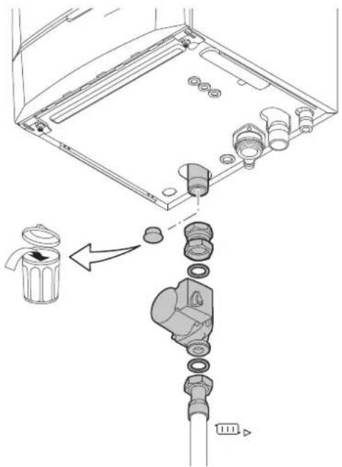
Fig.9 Connecting the CH return
natural_image
Diagram of a mechanical assembly with a labeled component and directional arrow (no text or symbols present)AD-0000023-01
-
For filling and tapping the boiler, install a filling and drain valve in the system.
-
Remove the dust cap from the CH return connection at the bottom of the boiler.
-
Fit the inlet pipe for CH water to the CH return connection.
-
Install the pump in the CH return pipe (if applicable).

See
For the pump's electrical connection: Connecting the pump, page 32

Important
Fit a service shut-off valve in the CH flow pipe and the CH return pipe to facilitate servicing work.

Caution
- When fitting service shut-off valves, position the filling and drain valve, the expansion vessel and the safety valve between the shut-off valve and the boiler.
- Carry out any welding work required at a safe distance from the boiler or before the boiler is fitted.
- If using synthetic pipes, follow the manufacturer's (connection) instructions.
- When installing open-vented systems, the cold feed and expansion tank heights must comply with the requirements laid down in the Health and Safety Executive publication PM5. The Quinta Pro boilers require a minimum static height of 3 m (Quinta Pro 30/45/55/65/90) or 5 m (Quinta Pro 115).
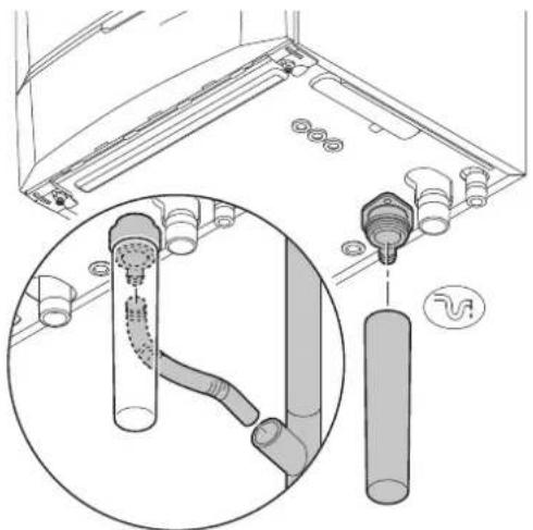
Fig.10 Connecting the condensate discharge pipe
natural_image
Technical diagram showing a pipe installation with a magnified inset of the pipe connection (no text or symbols present)AD-0000024-01
6.3.3 Connecting the expansion vessel
- Ensure that there is an expansion vessel with the correct volume and inlet pressure.
- Fit the expansion vessel on the central heating return pipe
6.3.4 Connecting the condensate discharge pipe
- Fit a plastic drain pipe of ∅ 32 mm or larger, terminating in the drain.
- Insert the flexible condensate drain hose into the pipe.
- Fit a stench-trap or siphon in the drain pipe.

Danger
The siphon must always be filled with water. This prevents flue gases from entering the room.

Caution
- Never seal the condensate drain.
- The drain pipe must slope down at least 30 mm per metre, the maximum horizontal length is 5 metres.
• Condensed water must not be discharged into a gutter.
6.4 Gas connection
Fig.11 Connecting the gas pipe
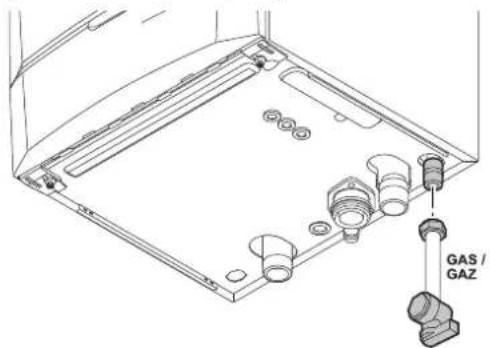
• Before starting work on the gas pipes, turn off the main gas tap.
- Before installing, check that the gas meter has sufficient capacity. Take into account the consumption of all appliances.
- Notify the local energy company if the gas meter has insufficient capacity.
-
Remove the dust cap from the gas supply pipe GASH the bottom of the boiler.
-
Fit the gas supply pipe.
-
Fit a gas tap in this pipe, directly underneath the boiler.
-
Fit the gas pipe to the gas tap.

Caution
- Remove dirt and dust from the gas pipe.
• Always perform welding work at a sufficient distance from the boiler. - Place a gas filter to prevent pollution of the gas valve unit.
6.5 Air supply/flue gas connections
The boiler is suitable for the following types of flue gas connections:

For more information, see
Certifications, page 12
6.5.1 Classification
This classification is specified in more detail in the table in accordance with C€
Tab.12 Types of flue gas connections
| Type Version | Description | |
| B_23 B_23P^(1) | Open Without down-draught diverter.·Flue gas discharge via the roof.·Air from the installation area. | |
| B_33 | Open Without down-draught diverter.·Common flue gas discharge via the roof (depression).·Flue gas discharge rinsed with air, air from the installation area (special construction). | |
| C_13 | Closed Discharge in the outside wall.·Inlet opening for the air supply is in the same pressure zone as the discharge (e.g. a combined outside wall feed-through). | |
| C_33 | Closed Flue gas discharge via the roof.·Inlet opening for the air supply is in the same pressure zone as the discharge (e.g. a concentric roof feed-through). | |
| C_43^(2) | Closed/cascade Joint air supply and flue gas discharge duct (CLV system):- Concentric (preferably).- Parallel (if concentric is not possible).·Overpressure cascade | |
| C_53 | Closed Closed unit.·Separate air supply duct.Separate flue gas discharge duct.Discharging into different pressure areas. | |
| C_63 | Closed This type of unit is supplied by the manufacturer without a supply and discharge sys-tem. | |
| C_83^(3) | Closed The appliance can be connected to what is known as a semi-CLV system (common flue gas outlet and individual air supply). | |
| C_93^(4) | Closed Air supply and flue gas discharge duct in shaft or ducted:- Concentric.- Air supply from existing duct.- Flue gas discharge via the roof.- Inlet opening for the air supply is in the same pressure zone as the discharge. | |
| (1) Also pressure class P1(2) EN 15502-2-1: 0.5 mbar suction due to depression(3) 4 mbar depression can occur(4) See table for minimum dimensions of shaft or duct | ||
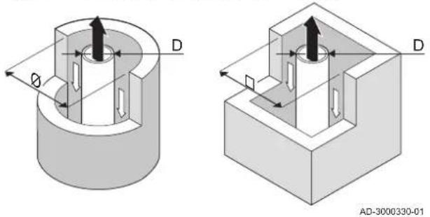
■ Shaft dimensions
Fig.12 Minimum dimensions of shaft or duct
natural_image
Technical diagrams of two mechanical components with directional arrows and dimension labels (no text or symbols beyond labels)Tab.13 Minimum dimensions of shaft or duct
| Type Version | Diameter (D) Without | air supply With air | supply | |||
| ∅ duct □ duct ∅ duct □ duct | ||||||
| C_93 | Rigid 60 mm 110 mm | 110 x 110 mm 120 | mm 110 x 110 mm | |||
| 80 mm 130 mm 1 | 30 x 130 mm 140 | mm 130 x 130 mm | ||||
| 100 mm 160 mm | 160 x 160 mm 170 | mm 160 x 160 mm | ||||
| Type Version | Diameter (D) Without air supply With air | supply | |||
| ∅ duct □ duct ∅ duct □ duct | |||||
| C_93 | Flexible 60 mm 110 mm | 110 x 110 mm | 20 mm 110 x 110 mm | ||
| 80 mm 130 mm | 30 x 130 mm 145 mm 130 x 130 mm | ||||
| 100 mm 160 mm | 160 x 160 mm 170 mm 160 x 160 mm | ||||
| C_93 | Concentric 60/100 mm | 120 mm 120 x 120 mm 120 mm 120 mm 120 mm | |||
| 80/125 mm 145 mm | 145 mm 145 x 145 mm | mm | |||
| 100/150 mm 170 mm | 170 mm 170 x 170 mm | 170 mm | |||
6.5.2 Outlets
Flue systems (roof feed-through and outside wall feed-through) must be supplied by the following manufacturers:
- Centrotherm
- Cox Geelen
- Muelink & Grol
• Natalini - Poujoulat
- Ubbink

Important
Where regulations stipulate that a wire grille must be fitted, use a suitable grille made from stainless steel.
Boiler-specific roof and outside wall feed-through kits are also available.

Note
Contact us for more information.
6.5.3 Material

Warning
- The coupling and connection methods may vary depending on the manufacturer. It is not permitted to combine pipes, coupling and connection methods from different manufacturers.
- The materials used must comply with the prevailing regulations and standards.
Tab.14 Flue gas outlet pipework materials
| Design(1) | Material(2) |
| Single-wall, rigid Thick-walled, aluminiumPlastic T120Stainless steel | |
| Flexible Plastic T120 | •Stainless steel |
| (1) The sealing must conform to pressure class 1(2) With CE marking | |
Tab.15 Air supply pipework materials
| Version | Material |
| Single-wall, rigid Aluminium | PlasticStainless steel |
| Version Material | |
| Flexible Aluminium | PlasticStainless steel |
6.5.4 Length of the air and flue gas pipes

Important
- When using bends, the maximum chimney length (L) must be shortened according to the reduction table.
- The boiler is also suitable for longer chimney lengths and diameters other than those specified in the tables. Contact us for more information.
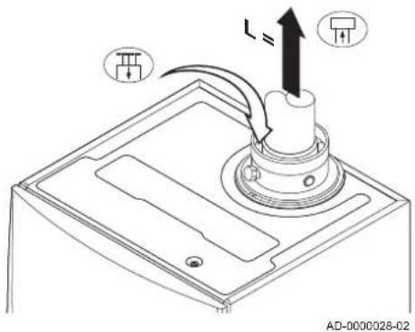
■ Room-ventilated version ( B_23 , B_23P , B_33 )
Fig.13 Room-ventilated version
text_image
L= AD-0000028-02
Connecting the flue gas outlet
Connecting the air supply
With a room-ventilated version, the air supply opening stays open; only the flue gas outlet opening is connected. This will ensure that the boiler obtains the necessary combustion air directly from the installation area.

Caution
• The air supply opening must stay open.
- The installation area must be equipped with the necessary air supply openings. These openings must not be obstructed or shut off.
Tab.16 Maximum chimney length (L)
| Diameter 80 mm 90 mm 100 mm 110 mm | 130 mm^(1) | ||||
| Quinta Pro 30 33 m 40 m | 40 m^(1) | 40 m^(1) | 40 m^(1) | ||
| Quinta Pro 45 39 m | 40 m^(1) | 40 m^(1) | 40 m^(1) | 40 m^(1) | |
| Quinta Pro 55 16 m 26 m 39 m | 40 m^(1) | 40 m^(1) | |||
| Quinta Pro 65 11 m 17 m 26 m 40 m | 40 m^(1) | ||||
| Quinta Pro 90 10 m 16 m 24 m 40 m | 40 m^(1) | ||||
| Quinta Pro 115 8 m 13 m 19 m 38 m | 40 m^(1) | ||||
| (1) Retaining the maximum chimney length, it is possible to use an extra 5 × 90^ or 10 × 45^ elbows. | |||||
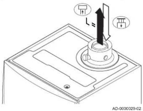
■ Room-sealed version ( C_13 , C_33 , C_63 , C_93 )
Fig.14 Room-sealed version (concentric)
text_image
L= AD-0000029-02
Connecting the flue gas outlet
Connecting the air supply
With a room-sealed version, both the flue gas outlet and the air supply openings are connected (concentrically).
Tab.17 Maximum chimney length (L)
| Diameter 80/125 mm | 100/150 mm^(1) | |
| Quinta Pro 30 20 m | 20 m^(1) | |
| Quinta Pro 45 20 m | 20 m^(1) | |
| Quinta Pro 55 8 m | 20 m^(1) | |
| Quinta Pro 65 4 m 18 m | ||
| Quinta Pro 90 4 m 17 m | ||
| Quinta Pro 115 - 13 m | ||
| (1) Retaining the maximum chimney length, it is possible to use an extra 5 x 90° or 10 x 45° elbows. | ||
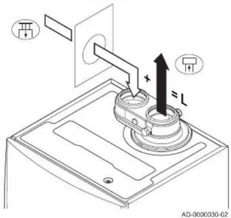
■ Connection in different pressure areas ( C_53 , C_83 )
Fig.15 Different pressure areas
text_image
AD-000030-02Connecting the flue gas outlet Connecting the air supply
A 100/100 mm flue gas adapter (accessory) must be fitted for this connection.
Combustion air supply and flue gas discharge are possible in different pressure areas and semi-CLV systems, with the exception of the coastal area. The maximum permitted height difference between the combustion air supply and the flue gas outlet is 36 m.
Tab.18 Maximum chimney length (L)
| Diameter 80 mm 90 mm 100 mm 110 mm | 130 mm^(1) | ||||
| Quinta Pro 30 17 m 29 m 40 m | 40 m^(1) | 40 m^(1) | |||
| Quinta Pro 45 29 m 40 m | 40 m^(1) | 40 m^(1) | 40 m^(1) | ||
| Quinta Pro 55 9 m 17 m 27 m 40 m | 40 m^(1) | ||||
| Quinta Pro 65 5 m 10 m 16 m 34 m | 40 m^(1) | ||||
| Quinta Pro 90 - - 17 m 37 m | 40 m^(1) | ||||
| Quinta Pro 115 | - | - | 14 m 31 m | 40 m^(1) | |
| (1) Retaining the maximum chimney length, it is possible to use an extra 5 × 90^ or 10 × 45^ elbows. | |||||
■ Reduction table
Tab.19 Pipe reduction for each element used (parallel)
| Diameter | 60 mm | 70 mm | 80 mm | 90 mm | 100 mm | 110 mm | 130 mm |
| 45° bend | 0.9 m | 1.1 m | 1.2 m | 1.3 m | 1.4 m | 1.5 m | 1.6 m |
| 90° bend | 3.1 m | 3.5 m | 4.0 m | 4.5 m | 4.9 m | 5.4 m | 6.2 m |
Tab.20 Pipe reduction for each element used (concentric)
| Diameter | 60/100 mm | 80/125 mm | 100/150 mm |
| 45° bend | 1.0 m | 1.0 m | 1.0 m |
| 90° bend | 2.0 m | 2.0 m | 2.0 m |
6.5.5 Additional guidelines
- For installing the flue gas outlet and air supply materials, refer to the instructions of the manufacturer of the relevant material. If the flue gas outlet and air supply materials are not installed in accordance with the instructions (e.g. not leakproof, not properly bracketed), this can result in dangerous situations and/or physical injury. After installation, check at least all flue gas outlet and air supply parts for tightness.
- Direct connection of the flue gas outlet to structural ducts is not permitted because of condensation.
- Always clean shafts thoroughly when using lining pipes and/or an air supply connection.
- It must be possible to inspect the lining duct.
- If condensate from a plastic or stainless steel pipe section can flow back to an aluminium part in the flue gas outlet, this condensate must be discharged via a collector before it reaches the aluminium.
- With longer lengths of aluminium flue gas outlet pipes, relatively large quantities of corrosion products flowing back out of the outlet pipes together with the condensate must be taken into account the first time. Clean the siphon of the appliance regularly or install an extra condensate collector above the unit.
- Make sure that the flue gas outlet pipe towards the boiler has a sufficient gradient (at least 50 mm per metre) and that there is a sufficient condensate collector and discharge (at least 1 m before the outlet of the boiler). The bends used must be larger than 90° to guarantee the gradient and a good seal on the lip rings.

Important
Contact us for more information.
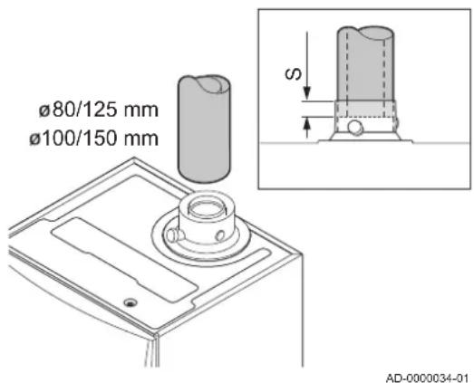
6.5.6 Connecting the flue gas outlet and air supply
Fig.16 Connecting the flue gas outlet and air supply
text_image
Ø80/125 mm Ø100/150 mm S AD-0000034-01S Insertion depth 25 mm
- Connect the flue gas outlet pipe and the air supply pipe to the boiler.
- Fit the subsequent flue gas outlet pipes and air supply pipes in accordance with the manufacturer's instructions.

Caution
- The pipes must not be resting on the boiler.
- Fit the horizontal parts sloping down towards the boiler, with a gradient of 50 mm per metre.
6.6 Electrical connections
6.6.1 Control unit
The table gives important connection values for the control unit.
Tab.21 Connection values for control unit
| Supply voltage 230 VAC/50 Hz | |
| Main fuse value F1 (230 VAC) 6.3 AT | |
| Fuse value F2 (230 VAC) 2 AT | |
| Fan 230 VAC |

Danger of electric shock
The following components of the boiler are connected to a 230 V power supply:
• Electrical connection to circulating pump.
• Electrical connection to gas combination block.
• Electrical connection to fan.
- Control unit.
- Ignition transformer.
• Power supply cable connection.
The boiler has a three-wire mains lead (lead length 1.5 m) and is suitable for a 230 VAC/50 Hz power supply with a phase/neutral/earth system. The boiler is not phase sensitive. The power supply cable is connected to the X1 connector. A spare fuse can be found in the housing of the control unit.

Caution
- Always order a replacement mains lead from Remeha. The power supply cable should only be replaced by Remeha, or by an installer certified by Remeha.
- The boiler switch must be easily accessible at all times.
The boiler has several control, protection and regulation connection options. The standard PCB can be extended with optional PCBs.

For more information, see
Optional electrical connections, page 85
6.6.2 Recommendations

Warning
- Electrical connections must always be made with the power supply disconnected and only by qualified installers.
- The boiler is completely pre-wired. Never change the internal connections of the control panel.
- Make sure you establish an earth connection before connecting the electricity.
Establish the electrical connections in accordance with:
- The instructions of the current standards.
- The instructions of the wiring diagrams supplied with the boiler.
• The recommendations in this manual. - Separate the sensor cables from the 230 V cables.
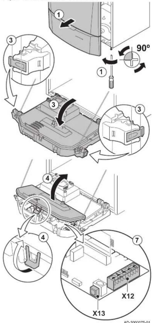
6.6.3 Access to the connectors
Fig.17 Access to the connectors
text_image
Technical diagram illustrating the assembly of a device with numbered components and angular adjustment, including 90° rotation and component layout.Various thermostats and regulators can be connected to the standard PCB (PCU) (connector X12).
Access to the connectors:
- Unscrew the two screws located under the front housing by a quarter turn and remove the front housing.
- Guide the cables from the regulator or the thermostat through the round grommet(s) on the right-hand side of the boiler bottom plate.
- Tilt the instrument box forwards by opening the clips on the sides.
- Open the instrument box by opening the clip on the front.
- Guide the relevant connection cable(s) through the instrument box via the grommet(s) provided.
- Unscrew the strain relief clamps as required (in front of the connector) and guide the cables underneath.
- Connect the cables to the appropriate terminals on the connector.
- Screw the strain relief clamps securely into position and close the control panel.
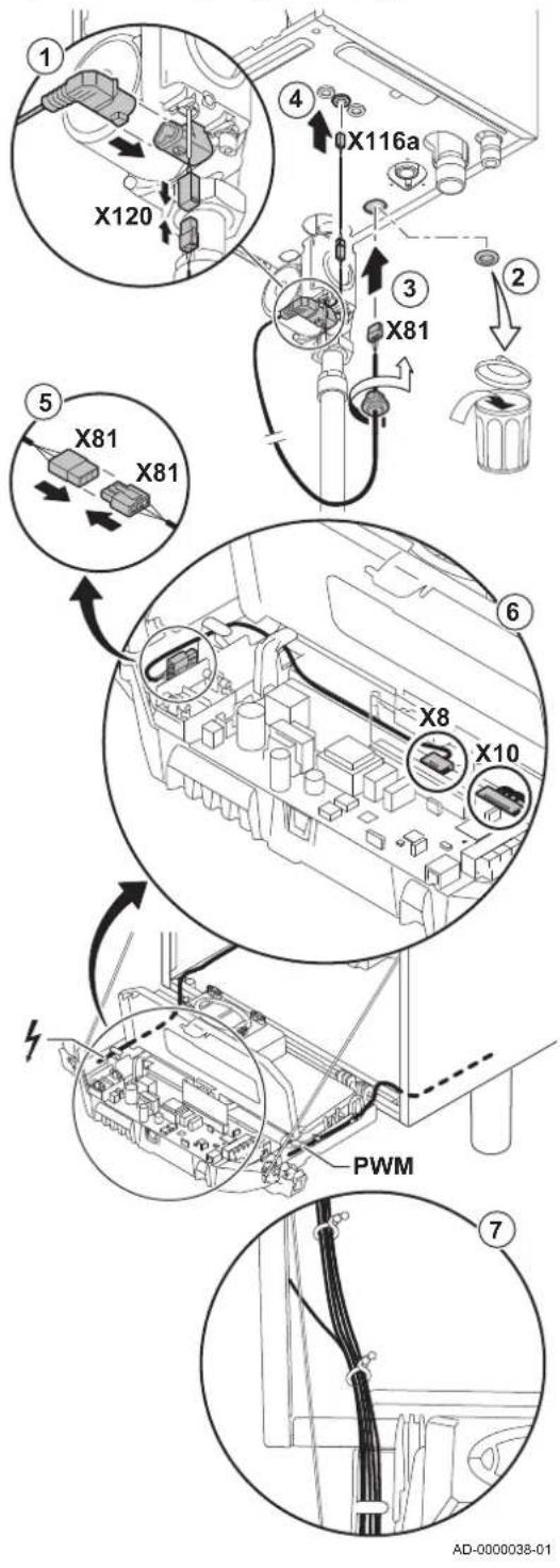
Fig.18 Connecting the power supply cable
text_image
① X120 ④ X116a ③ X81 ② X81 X81 ⑤ X8 X10 PWM ⑦ AD-0000038-016.6.4 Connection options for the standard PCB
■ Connecting the PWM pump
The energy-efficient modulating pump must be connected to the standard PCB of the PCU. Proceed as follows:
- Connect the power supply cable and the cable for the PWM signal to the pump.
- Remove the grommet from the opening in the middle of the base of the boiler.
- Pass the pump power supply cable through the base of the boiler and seal the opening by tightening the bayonet fitting to the cable.
- Pass the PWM cable from the pump through one of the grommets on the right in the base of the boiler.
- Connect the pump power supply cable to the cable in the instrument box that is connected with connector X8.
- Connect the pump PWM cable to the cable in the instrument box that is connected with connector X10.
- Add the pump cables to the cable bundles by opening and closing the cable bundle bands.
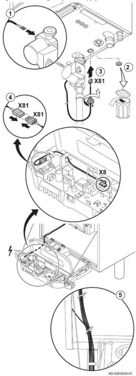
Fig.19 Connecting the power supply cable
text_image
Technical diagram showing exploded view of a mechanical assembly with labeled components and directional arrows indicating assembly steps.■ Connecting the pump
The pump must be connected to the standard PCB of the PCU. Proceed as follows:
- Connect the cable supplied with the boiler to the pump.
- Remove the grommet from the opening in the middle of the base of the boiler.
- Pass the pump cable through the base of the boiler and seal the opening by tightening the bayonet fitting to the cable.
- Connect the pump cable to the cable in the instrument box that is connected with connector X8.
- Add the pump cable to the cable bundles by opening and closing the cable bundle bands.
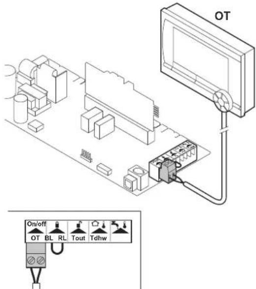
Fig.20 Connecting modulating thermostat
text_image
OT On/off OT BL RL Tout TdhwAD-0000046-01
Fig.21 Connecting the on/off thermostat
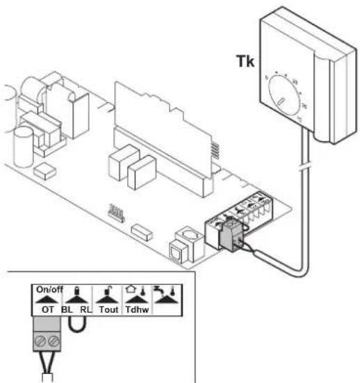
text_image
Tk On/off OT BL RL Tout TdhwAD-0000047-01
■ Connecting modulating thermostat
OT OpenTherm thermostat
The boiler is fitted with an OpenTherm connection as standard. As a result, modulating OpenTherm thermostats (room-temperature, weather-compensated and cascade thermostats) can be connected without further modifications. The boiler is also suitable for OpenTherm Smart Power.
- In the case of a room thermostat: install the thermostat in a reference room.
- Connect the two-wire cable of the thermostat to the On/Off OT terminals of the connector. It does not matter which wire is connected to which cable clamp.

Important
If the tap water temperature can be set on the OpenTherm thermostat, the boiler will supply this temperature, with the value set in the boiler as a maximum.
■ Connecting the on/off thermostat
Tk On/off ambient thermostat
The boiler is suitable for connection to a two-wire on/off ambient thermostat.
- Fit the thermostat in a reference room (generally the living room).
- Connect the two-wire cable of the thermostat to the On/off OT terminals of the connector. It does not matter which wire is connected to which cable clamp.
- Connect the power-stealing thermostat to the On/off OT terminals of the connector.

Important
If an ambient thermostat with an anticipation element is used, this must be completed via parameter P5
Fig.22 Connecting the frost thermostat
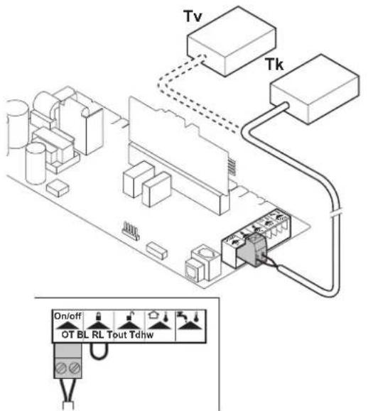
text_image
Tv Tk On/off OT BL RL Tout TdhwAD-0000049-01
■ Frost protection combined with on/off thermostat
When an on/off thermostat is used, the pipes and radiators in a frost-sensitive room can be protected by a frost thermostat. The radiator valve in the frost-sensitive room must be open.
- Place a frost thermostat (Tv) in a frost-sensitive room (e.g. a garage).
- Connect the frost thermostat (Tv) parallel to the on/off thermostat (Tk) on the On/Off OT terminals of the connector.
Important
When an OpenTherm thermostat is used, it is not possible to connect a frost thermostat parallel to the On/Off OT terminals. In that case, implement frost protection of the central heating system in combination with an outside sensor.
■ Frost protection combined with outside sensor
The central heating system can also be protected against frost in combination with an outside sensor. The radiator valve in the frost-sensitive room must be open.
- Connect the outside sensor to the Tout terminals of the connector.
The frost protection works as follows with an outside sensor:
- At an outside temperature lower than -10^ (can be set with parameter P30): the circulating pump switches on.
- At an outside temperature higher than -10^ (can be set with parameter P30): the circulating pump continues to run and then switches off.
■ Connecting an outside sensor
Fig.23 Connecting an outside sensor
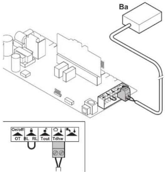
text_image
Ba On/off OT BL RL Tout TdhwAD-0000048-01
Ba Outside sensor
An outside sensor can be connected to the Tout terminals of the connector (accessory). In the event of an on/off thermostat, the boiler will regulate the temperature using the set point of the internal heating curve (F). Various parameter settings can be used to change the internal heating curve.
- Connect the two-wire cable to the Tout terminals of the connector.
Important
An OpenTherm controller can also use this outside sensor. In that case, the required internal heating curve must be set on the controller.
Fig.24 Heating curve
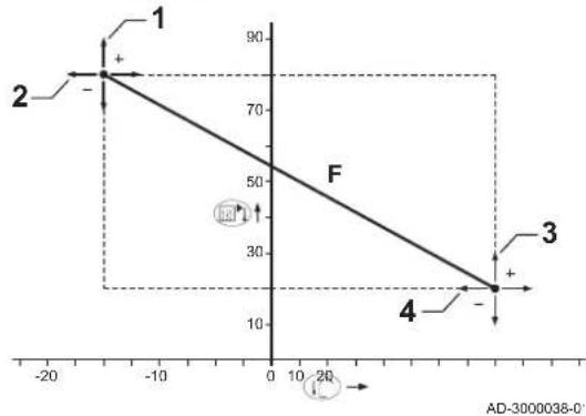
line
| Point | X | Y | |-------|------|-----| | 1 | -5 | 80 | | 2 | -5 | 75 | | 3 | 5 | 15 | | 4 | 5 | 10 |Fig.25 Connecting the calorifier sensor/calorifier thermostat
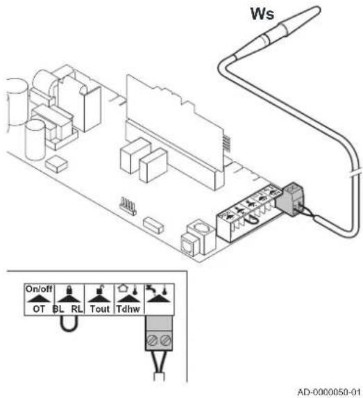
text_image
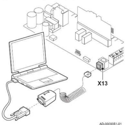
Ws On/off OT BL RL Tout Tdhw AD-0000050-01Fig.26 Connecting a PC/laptop
text_image
X13 AD-0000051-01- Setting the heating curve
1 P 1
2 P27
3 P26
4 P25
F Heating curve
If an outside temperature sensor is connected, it is possible to adapt the internal heating curve. The setting can be modified using parameters P1 P25, P26, P27
■ Connecting the calorifier sensor/calorifier thermostat
Ws Calorifier sensor
- Connect the calorifier sensor or calorifier thermostat to the Tdhw terminals of the connector.
■ Connecting a PC/laptop
A PC or laptop can be connected to the telephone connector using the optional Recom interface Using the Recom PC/Laptop service software, you can enter, change and read out various boiler settings.
Fig.27 Blocking input
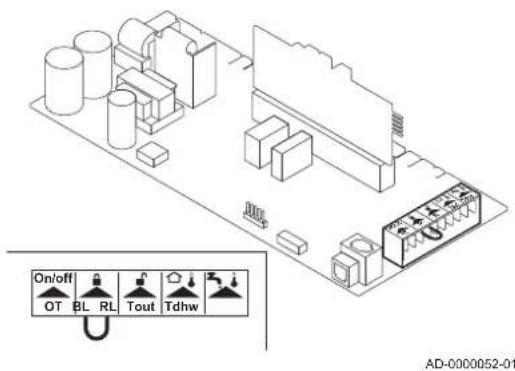
text_image
On/off OT BL RL Tout Tdhw AD-0000052-01Fig.28 Release input
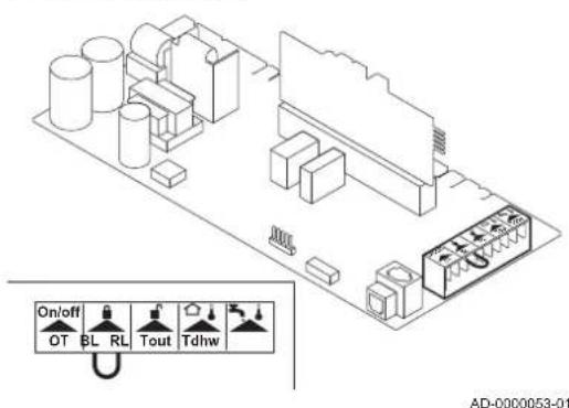
text_image
On/off OT BL RL Tout Tdhw AD-0000053-01Fig.29 Open housing for PCBs
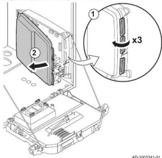
text_image
1 2 x3 AD-3000341-01■ Blocking input
The boiler has a blocking input. This input relates to the BL terminals of the connector.

Warning
Only suitable for potential-free contacts.

Important
First remove the bridge if this input is used.
The parameter _1, P_2 can be used to change the function of the input.

For more information, see
Changing the parameters, page 53
■ Release input
The boiler has a release input. This input relates to the RL terminals of the connector.

Warning
Only suitable for potential-free contacts.
The parameter P can be used to change the function of the input.
The parameter P can be used to change the wait time of the input.

For more information, see
Changing the parameters, page 53
6.6.5 PCBs
The PCBs are positioned in the PCB housing.
The following PCBs are already installed in the PCB housing:
- IF-01
- SCU-S02
- SCU-X01
Fig.30 IF-01 PCB
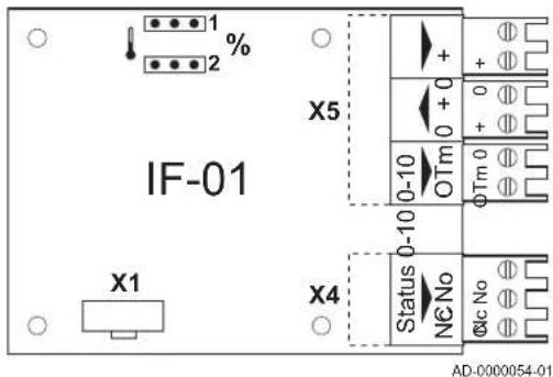
text_image
IF-01 X1 X4 Status 0-10 N6 No @c No AD-000054-01■ Connection options for the 0–10 V PCB (IF-01)
The IF-01 PCB can be built into the instrument box or the housing for the PCBs. See the instructions provided with the product.

Caution
Do not connect a frost thermostat or room thermostat to the boiler if using the 0–10 V PCB.
- Connecting the status relay (Nc)
If the boiler locks out, a relay is de-energised and the alarm can be transmitted via a potential-free contact (maximum 230 V, 1 A) on terminals Nc and C of the connector.
- Connection (OTm)
The interface uses OpenTherm to communicate with the boiler control unit. To make this possible, the OTm connection must be connected to the OpenTherm input of the boiler control unit. OTm
- Analogue input (0-10 V)
A choice can be made with this control between control based on temperature or heat output. The two controls are described briefly below.
- Connect the input signal to terminals 0–10 of the connector.
Tab.22 Temperature-based control (°C)
| Jumper 2 | Input signal (V) Temperature °C Description | ||
| 0–1.5 0–15 Boiler off | |||
| 1.5–1.8 15–18 Hysteresis | |||
| 1.8–10 18–100 Desired temperature | |||
Fig.31 Switch jumper (2)
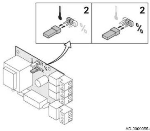
text_image
2 2 AD-0000055-4The 0–10 V signal controls the boiler supply temperature. This control modulates on the basis of flow temperature. The output varies between the minimum and maximum value on the basis of the flow temperature set point calculated by the controller.
A jumper (2) on the interface is used to select either temperature-based control (☐ or output-based control (%).
Tab.23 Control based on heat output
| Jumper 2 | Input signal (V) Heat output (%) Description | ||
| % | 0–2.0(1) | 0–20 Boiler off | |
| 2.0–2.2(1) | 20–22 Hysteresis | ||
| 2.0–10(1) | 20–100 Desired temperature | ||
| (1) Dependent on the minimum modulation depth (set speeds, standard 20%) | |||
The 0–10 V signal controls the boiler output. This control modulates on the basis of the heat output. The minimum output is linked to the boiler's modulation depth. The output varies between the minimum and maximum value on the basis of the value defined by the controller.
Fig.32 Switch jumper (1)
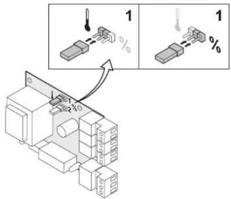
text_image
Technical diagram showing component assembly with labeled parts and directional arrows indicating assembly stepsAD-0000056-01
- Analogue output (0–10 V)
This feedback can be based on temperature or heat output. The two controls are described briefly below.
A jumper (1) on the interface is used to select either temperature (☐ or output (%).
Tab.24 Temperature message
| Jumper 1 | Output signal (V) Temperature °C Description | ||
| 0.5 – Alarm | |||
| 1–10 10–100 Supplied tempera- | ture | ||
Tab.25 Output message
| Jumper 2 | Output signal (V) Heat | output (%) Description | |
| % | 0 0–15 Boiler off | ||
| 0.5 15–20 Alarm | |||
| 2.0–10^(1) | 20–100 Supplied heat output | ||
| (1) Dependent on the minimum modulation depth (set speeds, standard 20%) | |||
■ Connection options for the PCB (SCU-S02)
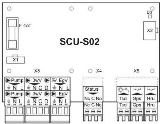
Fig.33 SCU-S02 PCB
text_image
SCU-S02 F 4AT X1 D3 X2 Pump 3wV EgV N L N C D N L Pump 3wV EgV N L N C D N L Status Nc C No Tsol Gps Hru Nc C No Tsol Gps HruAD-0000057-02
If the boiler is fitted with the PCB (SCU-S02), then this PCB is automatically recognised by the boiler's automatic control unit.

Important
On removing this PCB, the boiler will show error code ET08 prevent this error, an auto-detect must be carried out after removing this PCB.

See
For information on carrying out an auto-detect: Carrying out an auto-detect, page 57
The status signal D3 at the top right of the control PCB indicates the status:
• Continuous signal: PCB working normally
- Flashing signal: no connection
- No signal: no power or faulty PCB (check the wiring)
- Control of external CH pump (pump)
An external central heating pump can be connected to the pump terminals of the connector. The maximum power consumption is 400 VA.
- Control of external three-way valve (3wV)
The external three-way valve (230 VAC) can be used when connecting an indirectly heated calorifier. The neutral position of the three-way valve can be set using parameter P34
The three-way valve is connected as follows:
- N = neutral
• C = central heating
• D = calorifier
– Control of external sanitary hot water pump (3wV)
It is also possible to connect an external DHW pump to the terminals 3wV. Connect the pump as follows:
- N = N pump
• D = L pump
• ÷ = PE pump

Caution
If the neutral position of the three-way valve is adjusted with parameter Pthe pump must be connected as follows:
- N = N pump
• C = L pomp
• ÷ = PE pump
– Control of external gas valve (EgV)
If there is a heat demand, an alternating voltage of 230 VAC, 1 A (maximum) becomes available on the EgV terminals of the connector to control an external gas valve.
- Connecting the minimum gas pressure switch (Gps)
The minimum gas pressure switch blocks the boiler if the gas inlet pressure becomes too low.
- Connect the minimum gas pressure switch to the Gps terminals of the connector.
The presence of the gas pressure switch must be set using parameter P 4 1.
- Connecting a heat recovery unit (Hru)
- Connect the wires from the heat recovery unit to the Hru terminals of the connector.
The presence of the heat recovery unit must be set using parameter P4 2.
- Operation signal and error message (status)
You can choose between an alarm or operation signal using parameter P 40.
- If the boiler is in operation, the operating message can be connected via a potential-free contact (maximum 230 VAC, 1 A) to terminals Noand Cof the terminal connector.
- If the boiler locks out, the alarm can be relayed via a potential-free contact (maximum 230 VAC, 1 A) to terminals Ncand Cof the terminal connector.
■ Connection options for the PCB (SCU-X01)
The SCU-X01 PCB has two potential-free contacts (status), which can be configured as required. Depending on the setting, a maximum of two messages about the status of the boiler can be transmitted. See table. Select the messages required using rotary knobs SW1 and SW2. Use rotary knob SW1 for messages on the status connector X3. Use rotary knob SW2 for messages on the status connector X4.
Tab.26 Configuring the rotary knobs
| Position C- | NO C-NC | |
| 0 Alarm standby Alarm active | ||
| 1 Alarm inverted active Alarm inverted standby | ||
| 2 Burning standby Burning active | ||
| 3 Burning inverted active Burning inverted standby | ||
| 4 Burning low standby Burning low active | ||
| 5 Burning high standby Burning high active | ||
Fig.34 SCU-X01 PCB
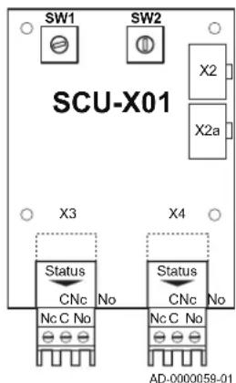
text_image
SW1 SW2 SCU-X01 X2 X2a X3 X4 Status CNc No Status CNc No Nc C No Nc C No AD-000058-01| Position C-NO C-NC | ||
| 6 Maintenance | message stand-by | Maintenance message active |
| 7 CH mode | standby CH mode active | |
| 8 DHW mode | standby DHW mode active | |
| 9 CH pump | standby CH pump active | |
6.7 Filling the installation
6.7.1 Water treatment
In many cases, the boiler and central heating system can be filled with normal tap water and water treatment will not be necessary.

Warning
Do not add chemical agents to the central heating water without consulting Remeha. For example: antifreeze, water softeners, pH-increasing or lowering agents, chemical additives and/or inhibitors. Such agents can cause errors in the boiler and damage to the heat exchanger.

Important
- For untreated water, the pH value of the water in the installation must be between 7 and 9 and for treated water between 7 and 8.5.
- The maximum hardness of the water in the installation must be between 0.5 and 20.0^ (dependent on the total heat output generated).
- More information is available in our Water quality regulations. Always adhere to the instructions in the aforementioned document.
6.7.2 Filling the siphon

Danger
The siphon must always be sufficiently filled with water. This prevents flue gases from entering the room.
Fig.35 Filling the siphon
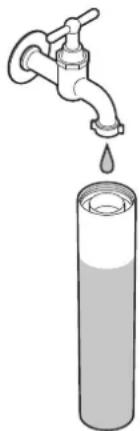
natural_image
Illustration of a faucet dispensing liquid into a test tube (no text or symbols)AD-0000064-01
- Remove the siphon.
- Fill the siphon up with water.
- Fit the siphon.
- Check whether the siphon is firmly fitted in the boiler.
6.7.3 Filling the system

Caution
Before filling, open the valves on every radiator in the installation.

Important
In order to be able to read off the water pressure from the boiler display, the boiler must be switched on.
- Fill the central heating system with clean tap water.

Important
The recommended water pressure is between 1.5 and 2 bar.
- Check the water-side connections for tightness.

Important
After switching on the power and if there is adequate water pressure, the boiler always runs through an automatic venting program lasting approximately 3 minutes (air may escape via the automatic air vent during filling). If the water pressure is lower than 0.8 bar, the symbol will appear. If the water pressure is too low, top up the CH installation.

Caution
- Carry out the filling within 30 minutes to avoid the venting program starting up. That would indeed be undesirable if the boiler is not filled. Switch the boiler off if the CH installation is not being topped up immediately.
- When venting, prevent water from getting into the boiler casing and electrical parts of the boiler.
7 Commissioning
7.1 General
Follow the steps set out in the paragraphs below to put the boiler into operation.

Warning
Do not put the boiler into operation if the supplied gas is not in accordance with the approved gas types.
7.2 Gas circuit
Fig.36 Gas valve unit measuring points
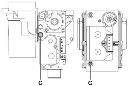
natural_image
Technical line drawing of mechanical components, showing front and side views with no visible text or symbolsAD-0000066-01

Warning
Ensure that the boiler is disconnected from the power supply.
- Open the main gas tap.
- Open the boiler gas tap.
- Unscrew the two screws located under the front housing by a quarter turn and remove the front housing.
- Tilt the instrument box forwards by opening the clips on the sides.
- Check the gas inlet pressure at the measuring point C on the gas valve unit.

Warning
- The gas pressure measured on measurement point C is the gas inlet pressure at the boiler connection point reduced by the resistance of the internal gas pipe. See Technical data, page 12
-
For authorised gas pressures, see: Unit categories, page 12
-
Vent the gas supply pipe by unscrewing the measuring point on the gas valve unit.
- Tighten the measuring point again when the pipe has been fully vented.
- Check all connections for gas tightness. The test pressure may be a maximum of 60 mbar.
7.3 Hydraulic circuit
- Check the siphon; it should be fully filled with clean water.
- Check the water-side connections for tightness.
7.4 Electrical connections
- Check the electrical connections.
7.5 Commissioning procedure

Warning
- Initial commissioning must be done by a qualified professional.
- If adapting to another gas type i.e. propane, the gas valve unit must be adjusted before switching on the boiler.

See
Adjusting to a different gas type, page 44

Important
On first firing the boiler, a smell may be present for a short period.
- Tilt the instrument box upwards again and fasten it using the clips located on the sides.
-
Open the main gas tap.
-
Open the boiler gas tap.
- Insert the boiler plug into an earthed socket.
- Switch the power on with the boiler's on/off switch.
- Set the components (thermostats, control) so that heat is demanded.
- The start-up program will start and cannot be interrupted. During the start-up cycle, the display shows the following information: A short test where all segments of the display are visible:
The version numbers are displayed alternately.
- A three-minute venting cycle is performed automatically.

Important
If a calorifier sensor is connected and the legionella protection function is activated, the boiler starts to heat the water in the DHW tank as soon as the venting programme has been completed.
By pressing the ◀key for a short time, the current operating status is shown on the display:
Tab.27 Operating status
| Heat demand | Heat demand stopped |
| 1: Fan on : Post-ventilation | 1 |
| 2: Burner ignition : Burner stop | 5 |
| 6: Post-circulation of the pump | |
| 3: CH operation : Standby | 0 |
In addition to ☐ in STAND-BY the display normally shows the water pressure and the symbols ☐ and ⚡️
Error during start-up procedure:
- No information is shown on the display:
- Check the mains supply voltage
- Check the main fuses
- Check the fuses on the control unit: (F1 = 6.3 AT, F2 = 2 AT)
- Check the connection of the mains lead to the connector X1 in the instrument box
- An error is indicated on the display by the error symbol and a flashing error code.
- The meaning of the error codes can be found in the error table.
- Press the RESET for 3 seconds to restart the boiler.

Important
If the ECO setting is on, then the boiler will not ignite for hot tap water production after central heating operation.
7.6 Gas settings
7.6.1 Adjusting to a different gas type

Warning
Only a qualified engineer may carry out the following operations.
The factory setting of the boiler is for operation with the natural gas group G20 (H gas).
Before operating with a different type of gas, carry out the following steps.
Tab.28 If operating on propane
| Boiler type Action | |
| Quinta Pro30 Rotate the adjusting screw A on the venturi 312 turns in a clockwise direction | |
| Quinta Pro 45 Rotate the adjusting screw A on the venturi 434 turns in a clockwise direction | |
| Quinta Pro 55 Rotate the adjusting screw A on the venturi 612 turns in a clockwise direction | |
| Quinta Pro 65 Rotate the adjusting screw A on the venturi 612 turns in a clockwise direction | |
| Quinta Pro 90 Replace the current gas valve unit with the propane gas valve unit according to the instructions supplied with the propane conversion kit | |
| Quinta Pro 115 Rotate the adjusting screw A in a clockwise direction until it is closed, then:Rotate the adjusting screw A on the gas valve unit 312-4 turns in an anticlockwise direction | |
- Set the fan speed as indicated in the table (if necessary). The set-
ting can be modified using parameters P 17, P and P 19 P
20.

See
Changing the parameters at installer level, page 54
- Check the setting of the gas/air ratio.

See
Checking and setting the gas/air ratio, page 45
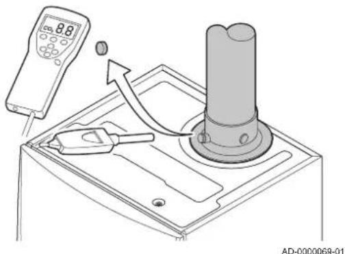
Fig.37 Flue gas measuring point
text_image
8.8 AD-0000069-017.6.2 Checking and setting the gas/air ratio
- Unscrew the cap from the flue gas measuring point.
- Insert the probe for the flue gas analyser into the measurement opening.

Warning
During measurement, seal the opening around the sensor fully.

Note
- The flue gas analyser must have a minimum accuracy of ± 0.25% O_2 / CO_2 .
-
The flue gas analyser must meet the requirements of BS 7927 or BS-EN 503793 and be calibrated according to the manufacturer's requirements.
-
Measure the percentage of O_2/CO_2 in the flue gases. Take measurements at full load and at low load.

Note
Measurements must be taken with the front housing off.
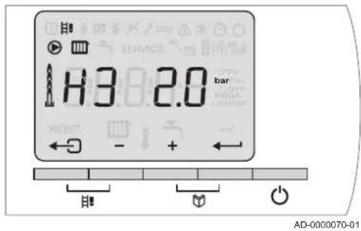
Fig.38 Setting to full load
text_image
H3 2.0 bar AD-0000070-01- Checking/setting values for O_2 / CO_2 at full load
-
Set the boiler to full load. Press the two keys at the same time. The display shows the symbol appears.
-
Measure the percentage of O_2/CO_2 in the flue gases.
-
Compare the measured value with the checking values in the table.
Tab.29 Checking/setting values for O 2 /CO 2 at full load for G20 (H gas)
| Values at full load for G20 (H gas) | O_2 (%)^(1) | CO_2 (%)^(1) |
| Quinta Pro 30 4,3 - 4,8 | (1) | 9,0(1)- 9,3 |
| Quinta Pro 45 4,3 - 4,8 | (1) | 9,0(1)- 9,3 |
| Quinta Pro 55 4,3 - 4,8 | (1) | 9,0(1)- 9,3 |
| Quinta Pro 65 4,3 - 4,8 | (1) | 9,0(1)- 9,3 |
| Quinta Pro 90 3,4 - 3,9 | (1) | 9,5(1)- 9,8 |
| Quinta Pro 115 4,2 - 4,7 | (1) | 9,1(1)- 9,4 |
| (1) Nominal value | ||
Tab.30 Checking/setting values for O 2/CO2 at full load for G31 (propane)
| Values at full load for G31 (propane) | O_2 (%) (1) | CO_2 (%)(1) |
| Quinta Pro 30 4,1 - 4,6 | (1) | 10,7(1)- 11,0 |
| Quinta Pro 45 4,1 - 4,6 | (1) | 10,7(1)- 11,0 |
| Quinta Pro 55 4,1 - 4,6 | (1) | 10,7(1)- 11,0 |
| Quinta Pro 65 4,1 - 4,6 | (1) | 10,7(1)- 11,0 |
| Quinta Pro 90 4,1 - 4,6 | (1) | 10,7(1)- 11,0 |
| Quinta Pro 115 4,4 - 4,9 | (1) | 10,5(1)- 10,8 |
| (1) Nominal value | ||
Fig.39 Position of adjusting screw A

natural_image
Technical line drawing of mechanical components with labeled parts A, showing exploded and assembled views (no text or symbols beyond labels)
Caution
- The O_2 values at full load must be lower than the O_2 values at part load.
-
The CO2 values at full load must be higher than the CO2 values at part load.
-
If the measured value is outside of the values given in the table, correct the gas/air ratio.
-
Using adjusting screw A, adjust the percentage of O_2/CO_2 for the gas type being used to the nominal value. This should always be inside the highest and lowest setting limit.
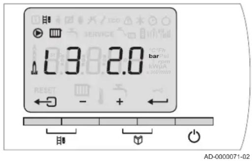
Fig.40 Setting to part load
text_image
13.0-2.0 bar kW/mA sol/min RESET - + AD-0000071-02- Checking/setting values for O_2 / CO_2 at part load
- Set the boiler to part load. Press the key several times until appears on the display.
L3 - Measure the percentage of O_2/CO_2 in the flue gases.
- Compare the measured value with the checking values in the table.
Tab.31 Checking/setting values for O 2 /CO 2 at part load for G20 (H gas)
| Values at part load for G20 (H gas) | O_2 (%)^(1) | CO_2 (%)^(1) |
| Quinta Pro 30 5,7 | ^(1) - 6,2 8,2 | - 8,5 ^(1) |
| Quinta Pro 45 5,7 | ^(1) - 6,2 8,2 | - 8,5 ^(1) |
| Quinta Pro 55 4,8 | ^(1) - 5,3 8.7 | - 9,0 ^(1) |
| Quinta Pro 65 4,8 | ^(1) - 5,3 8,7 | - 9,0 ^(1) |
| Quinta Pro 90 4,8 | ^(1) - 5,3 8,7 | - 9,0 ^(1) |
| Quinta Pro 115 5,6 | ^(1) - 6,1 8,3 | - 8,6 ^(1) |
| (1) Nominal value | ||
Tab.32 Checking/setting values for O 2 /CO 2 at part load for G31 (propane)
| Values at part load for G31 (propane) | O_2 (%) ^(1) | CO_2 (%) ^(1) |
| Quinta Pro 30 5,4 | ^(1) -5,9 9,9 | -10,2 ^(1) |
| Quinta Pro 45 5,4 | ^(1) -5,9 9,9 | -10,2 ^(1) |
| Quinta Pro 55 5,1 | ^(1) -5,6 10, | 1-10,4 ^(1) |
| Quinta Pro 65 5,1 | ^(1) -5,6 10, | 1-10,4 ^(1) |
| Quinta Pro 90 5,4 | ^(1) -5,9 9,9 | -10,2 ^(1) |
| Quinta Pro 115 5,7 | ^(1) -6,2 9,7 | -10,0 ^(1) |
| (1) Nominal value | ||

Caution
- The O_2 values at part load must be higher than the O_2 values at full load.
-
The CO2 values at part load must be lower than the CO2 values at full load.
-
If the measured value is outside of the values given in the table, correct the gas/air ratio.
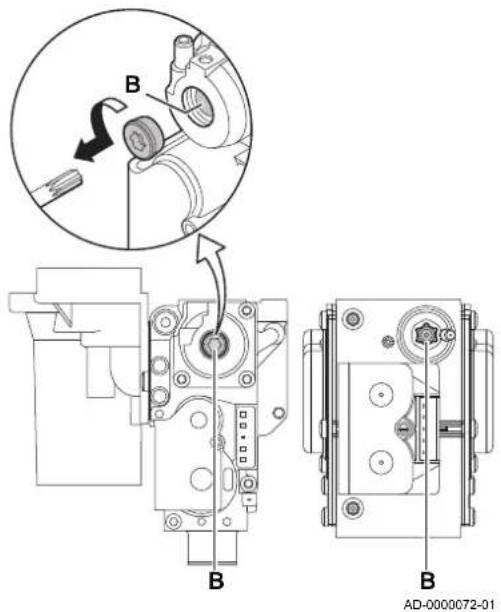
Fig.41 Position of adjusting screw B
-
Using adjusting screw B, adjust the percentage of O_2/CO_2 for the gas type being used to the nominal value. This should always be inside the highest and lowest setting limit.
-
Set the boiler back to the normal operating status.
7.7 Final instructions
- Remove the measuring equipment.
- Screw the cap on to the flue gas measuring point.
- Put the front casing back. Tighten the two screws by a quarter of a turn.
- Press the key to return the boiler to normal operating mode.
- Heat the CH system up to approximately 70°C.
- Switch the boiler off.
- Vent the central heating system after approx. 10 minutes.
- Turn on the boiler.
- Check the water pressure. If necessary: top up the central heating system.
- Specify the gas type used on the type plate.
- Instruct the user in the operation of the system, boiler and controller.
- Inform the user of the maintenance to be performed.
- Hand over all manuals to the user.
8 Operation
8.1 Use of the control panel
Fig.42 Control panel
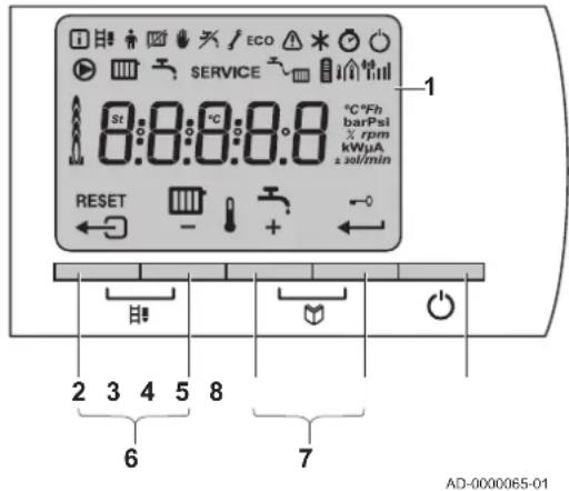
text_image
ECO SERVICE st:0:0:0:0:0 °C*Fh barPsi rpm kWμA ±30/min RESET - + - 1 2 3 4 5 8 6 7 AD-0000065-011 Display
2 ← Escape or RESET
3 CH temperature or +key
4 DHW temperature or key
5 ← Enter or Cancel key lockout
6 Chimney-sweeping keys
Press the 2 and 3 keys simultaneously.
7 Menu keys
Press the 4 and 5 keys simultaneously.
8 On/off switch
The display has several positions and symbols and provides information about the operating status of the boiler and any faults. A maintenance message may also appear on the display. Numbers, dots and/or letters may be shown. The symbols above the function keys indicate the current function.
- The display content can be changed using parameter P6
- The brightness of the display lighting can be changed using parameter PB.
Key lockout is activated by setting parameter FgG. If no key is pressed for 3 minutes, the display lighting switches off and only the current water pressure, the
← key for approximately 2 seconds to reactivate the display and the other keys. The symbol disappears from the display.
8.2 Shutdown
If the central heating is not due to be used for a long period of time, it is recommended that the boiler be disconnected from the power supply.
- Switch off the boiler's electrical connection.
- Shut off the gas supply.
- Keep the area frost-free.
8.3 Frost protection

Caution
- Drain the boiler and central heating system if you are not going to use your home or the building for a long time and there is a chance of frost.
- The frost protection does not work if the boiler is out of operation.
- The built-in boiler protection is only activated for the boiler and not for the system and radiators.
- Open the valves of all the radiators connected to the system.
Set the temperature control low, for example to 10^ C.
If there is no heat demand, the boiler will only switch on to protect itself against frost.
If the temperature of the central heating water in the boiler drops too low, the built-in boiler protection system is activated. This system works as follows:
- At a water temperature lower than 7^ , the heating pump starts.
- If the water temperature is lower than 4^ , the boiler switches on.
- If the water temperature is higher than 10^ the boiler switches off and the circulation pump continues to run for a short time.
To prevent the system and radiators freezing in frost-sensitive areas (e.g. a garage), a frost thermostat or outside sensor can be connected to the boiler.
9 Settings
9.1 Parameter descriptions
Tab.33 Factory setting
| Parameter | Description Adjustment range 30 45 | 55 65 90 115 | ||||||
| P1 | Flow temperature: T_SET | 20 to 90°C 80 80 80 80 80 80 | ||||||
| P2 | DHW temperature: T_SET | 40 to 65°C 55 55 55 55 55 55 | ||||||
| P3 | Boiler control/DHW | 0 = CH off/DHW off1 = CH on/DHW on2 = CH on/DHW off3 = CH off/DHW on | 1 1 1 | 1 1 1 | ||||
| P4 | ECO setting | 0 = Comfort1 = ECO setting2 = Controller dependent | 2 2 2 | 2 2 2 | ||||
| P5 | Anticipation resistance | 0 = No anticipation resist-ance for the ON/OFF ther-mostat1 = Anticipation resistance for the ON/OFF thermostat | 0 0 0 | 0 0 0 | ||||
| P6 | Display screen | 0 = Simple1 = Extended2 = Automatic switching to simple after 3 minutes3 = Automatic switching to simple after 3 minutes; key lock is active | 2 2 2 | 2 2 2 | ||||
| P7 | Post-circulation of the pump | 1 to 98 minutes99 minutes = continuous | 3 3 3 | 3 3 3 | ||||
| P8 | Brightness of display lighting | 0 = Dimmed1 = Bright | 1 1 1 | 1 1 1 | ||||
| P17 | Maximum fan speed (central heating) | G20 (H gas) x100 rpm 41 56 | 51 58 62 | 70 | ||||
| P18 | Maximum fan speed (DHW) G20 (H gas) x100 rpm 41 56 51 58 62 | 70 | ||||||
| P19 | Minimum fan speed (CH + DHW) G20 (H gas) x100 rpm 15 15 16 | 16 17 18 | ||||||
| P20 | Minimum fan speed (offset) G20 (H gas) 50 50 0 0 0 0 | |||||||
| P21 | Start speed G20 (H gas) x100 rpm 25 25 25 25 25 25 | |||||||
| P22 | Minimum water pressure 0–3 bar (x 0.1 bar) | 8 8 8 8 8 8 | ||||||
| P23 | Maximum flow temperature of sys-tem | 0 to 90°C | 90 90 | 90 90 90 90 90 | ||||
| P24 | Reserve | - | - | - | - | - | - | |
| P25 | Heat curve set point(Maximum outside temperature) | 0 to 30°C ^(1) | 20 20 | 20 20 20 20 20 | ||||
| P26 | Heat curve set point(Flow temperature) | 0 to 90°C ^(1) | 20 20 | 20 20 20 20 20 | ||||
| P27 | Heat curve set point(Minimum outside temperature) | -30 to 0°C ^(1) | -15 | -15 | -15 | -15 | -15 | -15 |
| P28 | Setting the pump speed(Minimum pump speed for central heating operation) | 2–10 (x 10%) | 4 4 4 | 4 4 4 | ||||
| P29 | Setting the pump speed(Maximum pump speed for central heating operation) | 2-10 (x 10%) 10 10 10 10 10 | 10 | |||||
| P30 | Frost protection temperature -30 to | 0°C -10 -10 -10 -10 -10 -10 | ||||||
| P31 | Legionella protection | 0 = Off1 = On(2)2 = Controller dependent | 1 1 1 | 1 1 1 | ||||
| P32 | Set point increase for calorifier 0 to | 20°C 20 20 20 20 20 20 | ||||||
| P33 | Switch on temperature for DHW calorifier sensor | 2 to 15°C 5 5 5 5 5 5 | ||||||
| P34 | Control of three-way valve | 0 = Normal1 = Reverse | 0 0 0 | 0 0 0 | ||||
| P35 | Boiler type | 0 = Solo1 = Open vented2 = Solo (progressive calorifier control) | 0 0 0 | 0 0 0 | ||||
| P36 | Blocking input function | 0 = Heating activated1 = Blocking frost protection2 = Blocking with frost protection3 = Lockout with frost protection(3) | 1 1 1 | 1 1 1 | ||||
| P37 | Release function | 0 = DHW on1 = Release input | 1 1 1 | 1 1 1 | ||||
| P38 | Release waiting time 0 to 255 seconds | 0 0 0 0 0 0 | ||||||
| P39 | Gas valve switching time 0 to 255 seconds | 0 0 0 0 0 0 | ||||||
| P40 | Fault relay function | 0 = Operation signal1 = Alarm signal | 1 1 1 | 1 1 1 | ||||
| P41 | GpS connected | 0 = Not connected1 = Connected | 0 0 0 | 0 0 0 | ||||
| P42 | HRU connected | 0 = Not connected1 = Connected | 0 0 0 | 0 0 0 | ||||
| P43 | Mains detection phase | 0 = Off1 = On | 0 0 0 | 0 0 0 | ||||
| P44 | Service message Do not change 1 | 1 1 1 1 | ||||||
| P45 | Service operating hours | Do not change | 175 | 175 | 175 | 175 | 175 | 175 |
| P46 | Service burning hours | Do not change | 30 30 | 30 30 30 30 30 | ||||
| P47 | Modulating startpoint | 1 to 30°C | 25 25 | 25 25 25 | 20(4) | |||
| P48 | DHW stabilisation time | 10 to 100 seconds | 100 | 100 | 100 | 100 | 100 | 100 |
| RJ | Detection of connected SCUs | 0 = No detection1 = Detection | 0 0 0 | 0 0 0 | ||||
| dF+ Factory setting | To restore the factory settings or when replacing the control unit, enter the values dF and dU from the data plate for parameters dF and dU | X Y | X Y | X Y | X Y | X Y | X Y | |
| (1) Only with outside sensor(2) After switching on, the boiler operates once a week at 65°C for the DHW(3) Pump only(4) If the boiler is being installed in a cascade system, set parameter Ro 257 | ||||||||
Tab.34 Adjustment for gas type G31 (propane)
| Parameter | Description 30 45 55 65 90 115 | ||||||
| P17 | Maximum fan speed (central heating) 38 51 48 54 60 67 | ||||||
| P18 | Maximum fan speed (DHW) 38 51 48 54 60 67 | ||||||
| P19 | Minimum fan speed (CH + DHW) 15 15 15 16 20 18 | ||||||
| P20 | Minimum fan speed (offset) 50 50 0 0 0 0 | ||||||
| P21 | Start speed 30 30 25 25 25 35 |
Tab.35 Adjustment for flue gas overpressure cascade
| Parameter | Description 30 45 55 65 90 115 | ||||||
| P19 | Minimum fan speed (CH + DHW) 18 18 18 18 | 19^(1) | 19 | ||||
| P20 | Minimum fan speed (offset) 0 0 0 0 0 0 | ||||||
| P21 | Start speed 25 25 25 25 25 25 | ||||||
| (1) Use the parameter setting for the gas type if the boiler has been adjusted for G31 (propane). | |||||||
9.2 Changing the parameters
The boiler's control unit is set for the most common central heating systems. These settings will ensure that virtually every central heating system operates effectively. The user or the installer can optimise the parameters as required.
For operation in open vented systems, parameter must be adjusted.
Fig.43 Changing the user parameters
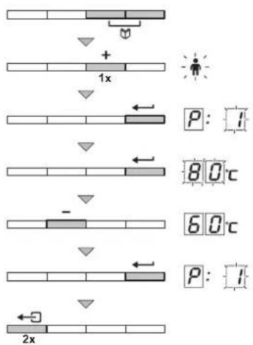
flowchart
graph TD
    A["Genes"] --> B["+"]
    B --> C["1x"]
    C --> D["2x"]
    D --> E["P: I"]
    E --> F["80°C"]
    F --> G["-"]
    G --> H["60°C"]
    H --> I["P: I"]
    I --> J["2x"]
AD-0000075-01
Fig.44 Inputting the access code
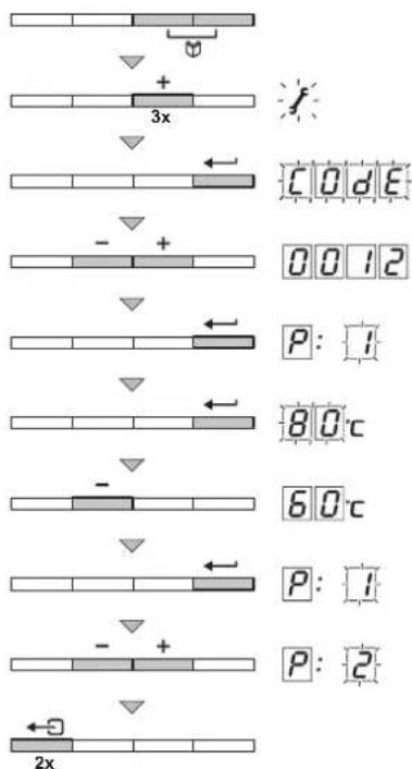
flowchart
graph TD
    A["3x"] --> B["+"]
    B --> C["Code"]
    D["-"] --> E["+"]
    E --> F["0012"]
    G["80c"] --> H["+"]
    H --> I["P: 1"]
    J["-"] --> K["+"]
    K --> L["60c"]
    M["-"] --> N["+"]
    N --> O["P: 1"]
    P["2x"] --> Q["+"]
    Q --> R["P: 2"]
AD-0000076-01

Caution
Modification of the factory settings may impair boiler operation.
9.2.1 Changing the user-level parameters
The parameters at user level (P01) can be changed by the user as required.
-
Press the two keys at the same time and then the key until the symbol flashes in the menu bar.
-
Select the user menu using the key. ⇒ P: appears with flashing . 1
-
Press the key again. → The set value (for example) appears and flashes.
-
Change the value by pressing the ☑ keys. In this example, use the ☑ key to change the value to °60
-
Confirm the value with the key. P: appears with flashing . 1
-
Press the *twice to leave this menu and return to the operation display.

Important
The other parameters at user level are changed in the same way as P. After step 2, use the key to go to the required parameter.
9.2.2 Changing the parameters at installer level
Parameters 1 may only be modified by a recognised installer. To prevent unwanted modifications to settings, some parameters can only be changed after the special access code 012 is entered.
-
Press the two keys at the same time and then press the key until the symbol flashes in the menu bar.
-
Select the installer menu using the key. →CODE appears on the display.
-
Use the or keys to set the installer code . 0012
-
To confirm, press the key. P: appears with a flashing . 1
-
Press the key again. ⇒ The value 80 (for example) appears and flashes.
-
Change the value by pressing the dr keys. In this example, press the +key to set the value to °G0
-
Press the key to confirm the value. P: appears with a flashing . 1
-
Set any other parameters by selecting them using the or keys.
-
Press the key twice to leave this menu and return to the operation display.

Important
The boiler also returns to operating status if no keys are pressed for 3 minutes.
9.2.3 Setting the maximum load for CH operation
Fig.45 Load Quinta Pro 30
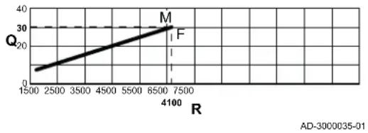
M Maximum heat input
F Factory setting
Q Input (Hi) (kW)
R Fan speed (rpm)
Fig.46 Load Quinta Pro 45
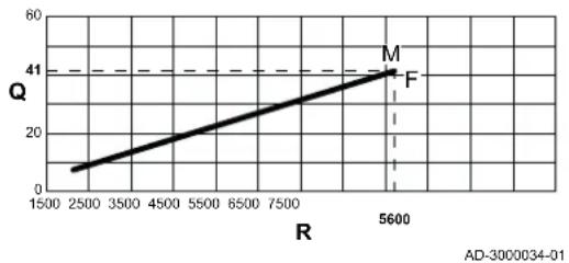
M Maximum heat input
F Factory setting
Q Input (Hi) (kW)
R Fan speed (rpm)
Fig.47 Load Quinta Pro 55
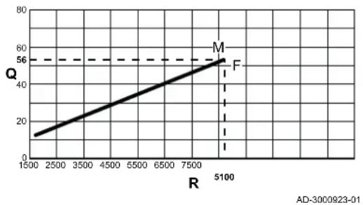
line
| R | Q | | ---- | --- | | 5100 | 56 |M Maximum heat input
F Factory setting
Q Input (Hi) (kW)
R Fan speed (rpm)
Fig.48 Load Quinta Pro 65
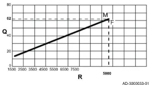
line
| R | Q | | ---- | --- | | 5800 | 62 |M Maximum heat input
F Factory setting
Q Input (Hi) (kW)
R Fan speed (rpm)
Fig.49 Load Quinta Pro 90
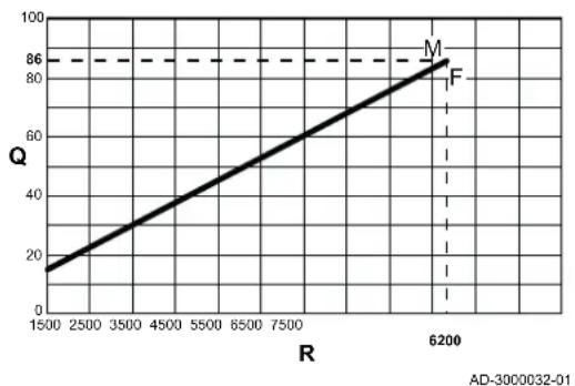
line
| R | Q | |---|---| | 1500 | 15 | | 2500 | 25 | | 3500 | 35 | | 4500 | 45 | | 5500 | 55 | | 6500 | 65 | | 7500 | 75 | | 8500 | 85 | | 9500 | 95 | | 10500 | 105 | | 11500 | 115 | | 12500 | 125 | | 13500 | 135 | | 14500 | 145 | | 15500 | 155 | | 16500 | 165 | | 17500 | 175 | | 18500 | 185 | | 19500 | 195 | | 20500 | 205 | | 21500 | 215 | | 22500 | 225 | | 23500 | 235 | | 24500 | 245 | | 25500 | 255 | | 26500 | 265 | | 27500 | 275 | | 28500 | 285 | | 29500 | 295 | | 30500 | 305 | | 31500 | 315 | | 32500 | 325 | | 33500 | 335 | | 34500 | 345 | | 35500 | 355 | | 36500 | 365 | | 37500 | 375 | | 38500 | 385 | | 39500 | 395 | | 40500 | 405 | | 41500 | 415 | | 42500 | 425 | | 43500 | 435 | | 44500 | 445 | | 45500 | 455 | | 46500 | 465 | | 47500 | 475 | | 48500 | 485 | | 49500 | 495 | | 50500 | 505 | | 51500 | 515 | | 52500 | 525 | | 53500 | 535 | | 54500 | 545 | | 55500 | 555 | | 56500 | 565 | | 57500 | 575 | | 58500 | 585 | | 59500 | 595 | | 60500 | 605 | | 61500 | 615 | | 62500 | 625 | | AD-300032-01M Maximum heat input
F Factory setting
Q Input (Hi) (kW)
R Fan speed (rpm)
Fig.50 Load Quinta Pro 115
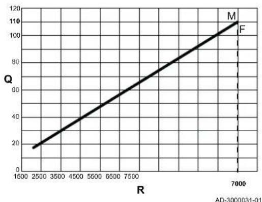
line
| R | Q | | ---- | --- | | 2500 | 20 | | 7000 | 110 |M Maximum heat input
F Factory setting
Q Input (Hi) (kW)
R Fan speed (rpm)
Fig.51 P 17 Change
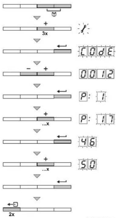
flowchart
graph TD
    A["3x plasmid"] --> B["Code segment"]
    B --> C["0012"]
    C --> D["P: 1"]
    D --> E["P: 17"]
    E --> F["46"]
    F --> G["50"]
    G --> H["2x plasmid"]
    style A fill:#f9f,stroke:#333
    style H fill:#bbf,stroke:#333
AD-0000077-01
See the graphs for the relationship between load and speed for natural gas. The speed can be changed using parameter P17. To do this, proceed as follows:
- Press the two menu keys at the same time and then press the key until the symbol flashes in the menu bar.
- Select the installer menu using the key.
→CODE appears on the display.
- Using the or keys, set the installer code . 0012
- To confirm, press the key.
P: appears with a flashing . 1
- Press the Key to go to parameter : .P 17
- To confirm, press the key!
- Press the key to increase the speed, for example from to 46 5 0 (see graphs for the corresponding output).
- To confirm, press the key!
- Press the *key twice to leave this menu and return to the operation display.
Fig.52 Resetting factory settings
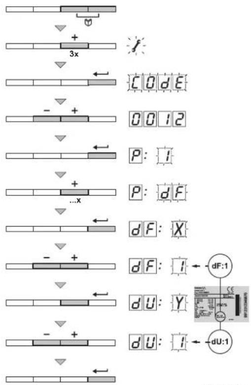
flowchart
graph TD
    A["3x"] --> B["Code"]
    B --> C["0012"]
    C --> D["P: I"]
    D --> E["...X"]
    E --> F["dF: X"]
    F --> G["dF: I"]
    G --> H["dU: Y"]
    H --> I["dU: I"]
    I --> J["dU: 1"]
    style A fill:#f9f,stroke:#333
    style J fill:#bbf,stroke:#333
AD-0000078-01
9.2.4 Return to the factory settings
- Press the two keys at the same time and then press the key until the symbol flashes in the menu bar.
- Select the installer menu using the key.
→CODE appears on the display.
- Use the or keys to set the installer code . 0012
- To confirm, press the key!
P: appears with a flashing . 1
- Press the key several times until: appears on the display with a flashing J.F
- To confirm, press the key.
⇒ √F appears with a flashing ☑This is the current value of X for dF. Check this against the value of X on the type plate.
- Enter the value of X shown on the type plate using the keys.
- To confirm, press the key!
⇒ : appears with a flashing. This is the current value of Y for dU. Check this against the value of Y on the type plate.
- Enter the value of Y shown on the type plate using the keys.
- To confirm, press the key!
→ The factory settings are reset.
- The display returns to the current operating mode.
Fig.53 Carrying out an auto-detect
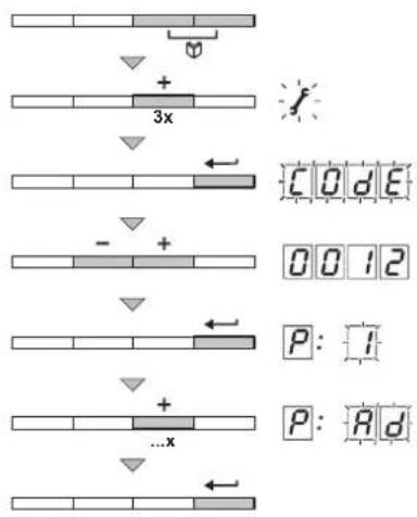
flowchart
graph TD
    A["3x"] --> B["+"]
    B --> C["Code"]
    D["..."] --> E["+"]
    E --> F["0012"]
    G["...x"] --> H["+"]
    H --> I["P: I"]
    J["f"] --> K["+"]
    K --> L["Code"]
    M["P: Rd"] --> N["+"]
AD-0000079-01
9.2.5 Carrying out an auto-detect
After removing a PCB, an auto-detect must be carried out. Proceed as follows:
- Press the two keys at the same time and then press the key until the symbol flashes in the menu bar.
- Select the installer menu using the key.
→CODE appears on the display.
- Use the or keys to set the installer code . 0012
- To confirm, press the key!
P: appears with a flashing . 1
- Press the Key several times until appears on the display with a flashing A.
- To confirm, press the key!
→ Auto-detect is carried out.
- The display returns to the current operating mode.
Fig.54 Setting manual mode
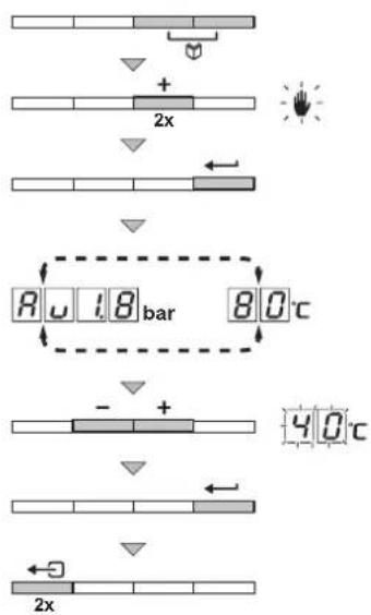
flowchart
graph TD
    A["2x"] --> B["+"]
    B --> C["Bar at 80°C"]
    C --> D["Bar at -1.8 bar"]
    D --> E["Bar at 40°C"]
    E --> F["Bar at -3.0 bar"]
    F --> G["2x"]
AD-0000080-01
9.2.6 Setting the manual mode
In some cases, it may be necessary to set the boiler to manual mode, for example when the controller has not yet been connected. The boiler can be set to automatic or manual mode via the symbol. Proceed as follows:
- Press the two keys at the same time and then press the key until the symbol flashes in the menu bar.
- Press the key, the display will show: ⇒ either the text with the current water pressure (only if a water pressure sensor is connected). or the minimum flow temperature value.
- Press the dr keys to temporarily increase this value in manual mode.
- To confirm, press the key. → The boiler is now set to manual mode.
- Press the key twice to leave this menu and return to the operation display.
9.3 Displaying the measured values
The control unit continually registers various values from the boiler and the connected sensors. These values can be read on the control panel of the boiler.
9.3.1 Reading the various current values
The following current values can be read in the information menu ⓘ
- S T = Status.
- S = Sub-status.
• T 1 = Flow temperature (°C).
• T2 = Return temperature (°C).
• T3 = Calorifier temperature (°C). - T|4 = Outside temperature (^) (only with outside sensor).
• T|S = Solar boiler temperature (°C). - SP = Internal set point (°C) .
• F L = Ionisation current ( A) .
• = Fan speed (rpm).
• = Water pressure (bar (MPa)). - P_o = Supplied relative heat output (%).
The current values can be read as follows:
Fig.55 Reading current values
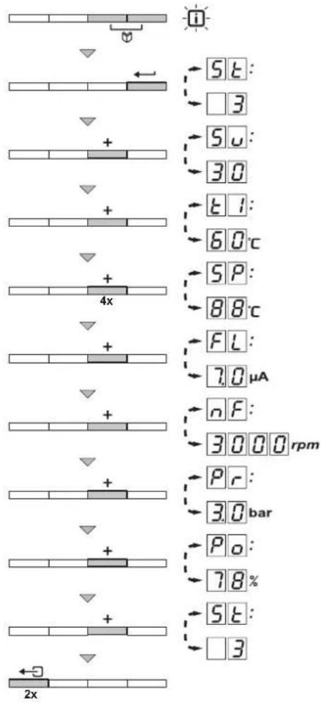
flowchart
graph TD
    A["Gene Symbol"] --> B{Condition:}
    B -->|Yes| C["5T: 3"]
    B -->|No| D["5U: 30"]
    C --> E["60°C"]
    D --> F["SP: 88°C"]
    E --> G["FL: 7.0μA"]
    F --> H["nF: 3000 rpm"]
    G --> I["Pr: 3.0bar"]
    H --> J["Po: 78%"]
    I --> K["5T: 3"]
    J --> L["2x"]
AD-0000073-02
- Press the two keys at the same time.
⇒ The isymbol flashes.
- Confirm by pressing the key!
The screen alternates between the parameter 5 and the current status, e.g. 3.
- Press the Key.
The screen alternates between the parameter 5 and the current sub-status, e.g. 30.
- Press the key.
The screen alternates between the parameter and the current flow temperature, e.g. B .
-
Press the key successively to scroll through the various parameters T2, T3, T4, T5
-
Press the Key.
The screen alternates between the parameter S and the internal setpoint, e.g. 88 °C.
- Press the Key.
The screen alternates between the parameter F and the current ionisation current, e.g. 70 μA.
- Press the Key.
The screen alternates between the parameter rad and the current fan speed, e.g. 3000
- Press the Key.
The screen alternates between the parameter F and the current water pressure, e.g. 30. If no water pressure sensor is connected, [-.-] appears on the display.
- Press the Key.
The screen alternates between the parameter P_and the current modulation percentage, e.g. 7%
- Press the Key.
→ The readout cycle starts again with the parameter 5T
- Press the key twice to exit this menu and return to the operation display.
9.3.2 Reading out the hour counter and percentage of successful starts
Fig.56 Reading out the hour counter
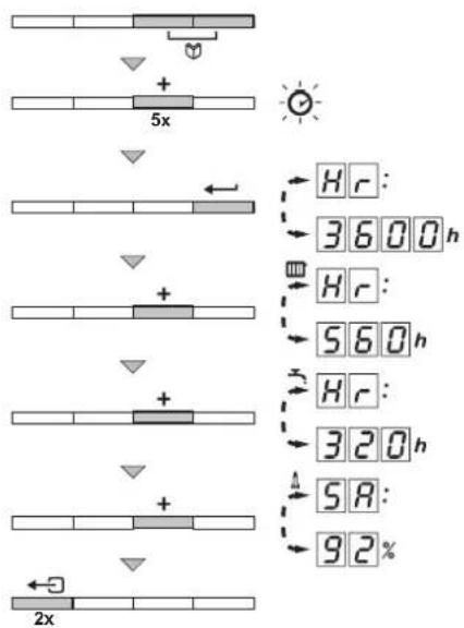
flowchart
graph TD
    A["5x"] --> B["+"]
    B --> C["2x"]
    D["HR: 3600h"] --> E["HR: 560h"]
    E --> F["HR: 320h"]
    F --> G["58h: 92%"]
AD-0000074-01
-
Press the two keys at the same time and then press the key until the symbol flashes in the menu bar.
-
Press the key.
→ The display alternates between H and the number of boiler operating hours, for example 3600.
- Press the Key; the display shows
→ The display alternates between H and the number of burning hours for CH operation, for example S60.
- Press the key; the display shows
The display alternates between 5 and the percentage of successful starts, for example 9.2 %.
- Press the *key twice to leave this menu and return to the operation display.
9.3.3 Status and sub-status
The information menu gives the following status and sub-status numbers:
Tab.36 Status and sub-status numbers
| Status Sub-status | SU | ||
| 0 | Stand-by mode Stand-by mode | 0 | |
| 1 | Boiler start (heat demand) Anti-hunting | 91 | |
| 2 | Control three-way valve | ||
| 3 | Start pump | ||
| 4 | Wait for the correct temperature before burner start | ||
| 2 | Burner start Open flue gas damper/external gas valve | 10 | |
| 11 | Increase fan speed | ||
| 13 | Pre-ventilation | ||
| 14 | Wait for release signal | ||
| 15 | Burner on | ||
| 17 | Pre-ignition | ||
| 18 | Main ignition | ||
| 19 | Flame detection | ||
| 20 | Intermediate ventilation | ||
| 3 | Burning on CH operation Temperature control | 30 | |
| 31 | Limited temperature control (ΔT protection) | ||
| 32 | Capacity control | ||
| 33 | Temperature gradient protection level 1 (modulate down) | ||
| 34 | Temperature gradient protection level 2 (low load) | ||
| 35 | Temperature gradient protection level 3 (blocking) | ||
| 36 | Modulate up for flame control | ||
| 37 | Temperature stabilisation time | ||
| 38 | Cold start | ||
| 4 | DHW mode active Temperature control | 40 | |
| 31 | Limited temperature control (ΔT protection) | ||
| 32 | Capacity control | ||
| 33 | Temperature gradient protection level 1 (modulate down) | ||
| 34 | Temperature gradient protection level 2 (low load) | ||
| 35 | Temperature gradient protection level 3 (blocking) | ||
| 36 | Modulate up for flame control | ||
| 37 | Temperature stabilisation time | ||
| 38 | Cold start | ||
| 5 | Burner stop Burner off | 40 | |
| 41 | Post ventilation | ||
| 42 | Close flue gas damper/external gas valve | ||
| 43 | Recirculation protection | ||
| 44 | Stop fan | ||
| 6 | Boiler stop (end of heat demand) Pump post circulation | ||
| 8 | Control stop Wait for burner start | 0 | |
| 1 | Anti-swing | ||
| 9 | Blocking | xxx | Blocking code xxx |
| 17 | Bleed Stand-by mode | 0 | |
| 2 | Control three-way valve | ||
| 3 | Start pump | ||
| 61 | Pump off | ||
| 62 | Control three-way valve | ||
10 Maintenance
10.1 General
The boiler does not require a lot of maintenance. Nevertheless, the boiler must be inspected and maintained periodically. To determine the best time for servicing, the boiler is equipped with an automatic service message. The control unit determines when this service message appears. Depending on boiler use, the first service message appears no later than 3 years after installation of the boiler.

Caution
- Maintenance operations must be completed by a qualified installer.
- During inspection or maintenance work, always replace all gaskets of the disassembled parts.
- Replace defective or worn parts with original spare parts.
• An annual inspection is mandatory.
10.2 Maintenance message
The boiler display will clearly indicate that a service is required at the appropriate time. Use the automatic service message for preventive maintenance, to keep faults to a minimum. The service messages show which service kit must be used. These service kits contain all parts and gaskets that are required for the relevant service. These service kits (A, B or C), put together by Remeha, are available from your spare parts supplier.

Important
A service message must be followed up within 2 months. Therefore, call your installer as soon as possible.

Important
If the iSense modulating thermostat is connected to the boiler, the thermostat can also display the maintenance message. Consult the thermostat manual.

Caution
Reset the maintenance message following every service.
10.2.1 Resetting the service messages
A service message on the boiler display must be reset by a qualified installer after the maintenance service has been carried out using the relevant service kit. Proceed as follows:
Fig.57 Setting the installer code
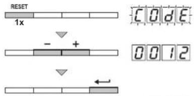
text_image
RESET 1x CODE - + 0012AD-0000081-01
- When the maintenance message is displayed, press the reset once.
CODE appears on the display.
-
Use the ☐r keys to set the installer code . 0012
-
Confirm by pressing the key.
⇒ The maintenance message is reset. The display returns to the current operating mode.
Fig.58 Starting a new service interval
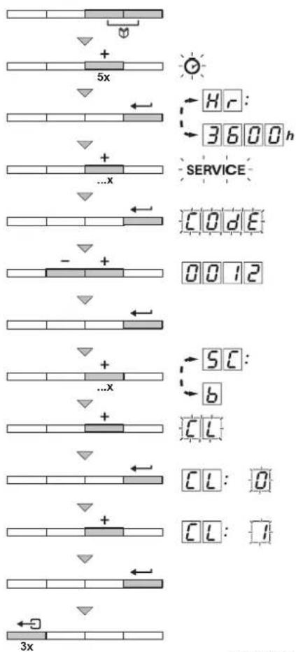
flowchart
graph TD
    A["5x"] --> B["+"]
    B --> C["3x"]
    D["..."] --> E["+"]
    E --> F["3x"]
    G["..."] --> H["+"]
    I["..."] --> J["+"]
    K["..."] --> L["+"]
    M["..."] --> N["...x"]
    O["..."] --> P["+"]
    Q["..."] --> R["+"]
    S["..."] --> T["...x"]
    U["..."] --> V["+"]
    W["..."] --> X["...x"]
    Y["..."] --> Z["...x"]
    AA["..."] --> AB["...x"]
    AC["..."] --> AD["...x"]
    AE["..."] --> AF["...x"]
    AG["..."] --> AH["...x"]
    AI["..."] --> AJ["...x"]
    AK["..."] --> AL["...x"]
    AM["..."] --> AN["...x"]
    AO["..."] --> AP["...x"]
    AQ["..."] --> AR["...x"]
    AS["..."] --> AT["...x"]
    AU["..."] --> AV["...x"]
    AW["..."] --> AX["...x"]
    AY["Hr"] --> AZ["3600h"]
    BA["SERVICE"] --> BB["C0dE"]
    BC["0012"] --> BD["0012"]
    BE["SC"] --> BF["b"]
    BG["CL"] --> BH["CL:0"]
    BI["CL:1"] --> BJ["CL:1"]
AD-0000082-01
10.2.2 Starting a new service interval
For an interim service it is advisable to read out in the boiler service menu what maintenance service should be carried out. Use the indicated Remeha service kits (A, B or C). This service message must be prevented by carrying out a reset, to start the next service interval. To do this, proceed as follows:
- Press the two menu keys at the same time and then press the key until the symbol flashes in the menu bar.

- Press the key.
The display alternates between H and the number of boiler operating hours, for example 3600
-
Press key several times until flash on the menu bar.
-
Press the key.
⇒ The display shows CODE
-
Using the or keys, set the installer code . 0012
-
Confirm by pressing the key.
-
Press the key several times until appears on the display with a flashing (for example). In this example, the next service message is SERVICE
-
Press the •key again.
CL appears on the display.
- Press the key.
→CL:O appears with a flashing O
-
Press the Key to adjust the setting to . 1
-
Confirm by pressing the key.
→ The new service interval begins.
- Press the key 3 times to leave this menu and return to the operation display.
10.3 Standard inspection and maintenance operations

Warning
Always wear safety goggles and a dust mask during cleaning work (involving compressed air).
For a service, always perform the following standard inspection and maintenance operations.

Caution
- Check whether all gaskets have been positioned properly (absolutely flat in the appropriate groove means they are gas tight).
- During the inspection and maintenance operations, water (drops, splashes) must never come into contact with the electrical parts.
10.3.1 Checking the water pressure
- Check the water pressure.
→ The water pressure must be at least 0.8 bar. If the water pressure is too low, the symbol will appear.

Important
For open vented systems, the water pressure must be at least 0.3 bar (Q30/Q45/Q65/Q90) or 0.5 bar (Q115).
- If necessary: top up the central heating system.
Fig.59 Checking flue gas outlet/air supply connections
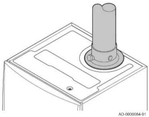
natural_image
Technical line drawing of a mechanical component with a cylindrical shaft and mounting base (no text or symbols)10.3.2 Checking the ionisation current
- Check the ionisation current at full load and at low load. ⇒ The value is stable after 1 minute.
- Clean or replace the ionisation/ignition electrode if the value is lower than 4 A.

For more information, see Replacing the ionisation/ignition electrode, page 67
10.3.3 Checking the flue gas outlet/air supply connections
- Check the flue gas outlet and air supply connections for condition and tightness.
10.3.4 Checking the combustion
Combustion is checked by measuring the O_2/CO_2 percentage in the flue gas outlet duct.

For more information, see Checking and setting the gas/air ratio, page 45
10.3.5 Checking the automatic air vent
Fig.60 Checking the automatic air vent
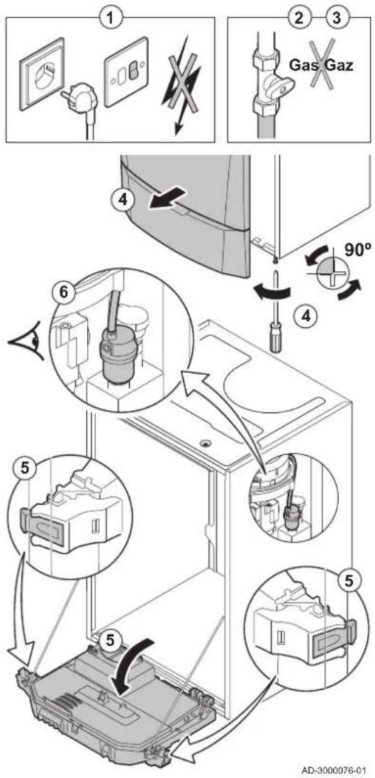
text_image
① ② ③ Gas Gaz ④ ⑤ ⑥ ⑤ ⑤ AD-3000076-01- Switch off the boiler's electrical connection.
- Close the gas tap under the boiler.
- Close the main gas tap.
- Unscrew the two screws located under the front housing by a quarter turn and remove the front housing.
- Tilt the instrument box forwards by opening the clips on the sides.
- Check whether water is visible in the hose of the automatic air vent.
- In the event of a leak, replace the air vent.
Fig.61 Cleaning the siphon
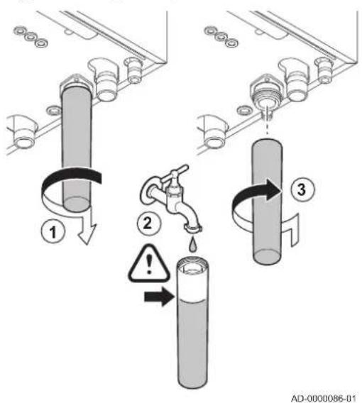
text_image
① ② ③ AD-0000086-0110.3.6 Cleaning the siphon

Danger
The siphon must always be sufficiently filled with water. This prevents flue gases from entering the room.
- Dismantle the siphon and clean it.
- Fill the siphon up with water.
- Fit the siphon.
Fig.62 Checking the burner and cleaning the heat exchanger
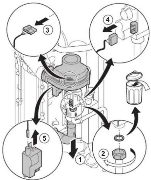
flowchart
graph TD
    A["1: Initial piping"] --> B["2: Bagging"]
    B --> C["3: Cable connection"]
    C --> D["4: Refrigeration unit"]
    D --> E["5: Bagging device"]
    E --> A
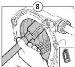
text_image
Technical diagram showing a mechanical assembly with labeled component 8 and an inset detail view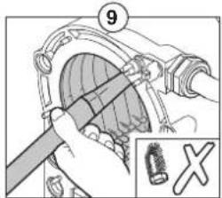
text_image
⑨ X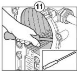
text_image
11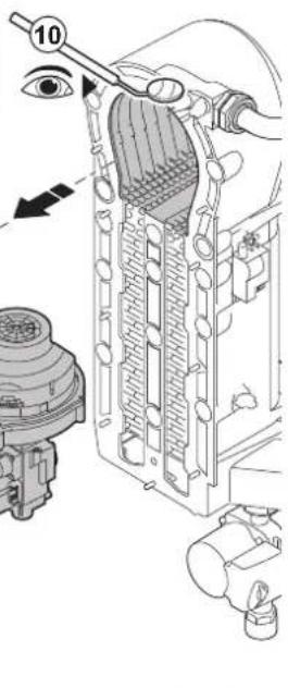
text_image
Technical diagram of a mechanical device with labeled parts and an eye indicatorAD-0000087-01
10.3.7 Checking the burner and cleaning the heat exchanger
- Remove the air inlet flue on the venturi.
- Loosen the gland on the gas valve unit.
- Remove the plugs from the fan.
- Remove the plugs from the gas valve unit.
- Remove the ignition electrode plug from the ignition transformer.
- Remove the front plate from the heat exchanger.
- Carefully lift the front plate, including the burner and fan, away from the heat exchanger.
- Use a vacuum cleaner fitted with a special endpiece (accessory) to clean the top part of the heat exchanger (combustion chamber).
- Thoroughly clean with the vacuum cleaner again without the top cleaning brush on the endpiece.
- Check (e.g. using a mirror) whether any visible contamination has been left behind. If it has, remove it with the vacuum cleaner.
- Clean the lower section of the heat exchanger with the special cleaning blade (accessory).
- Burner maintenance is almost never required; it is self-cleaning:
- If necessary, carefully clean the cylinder-shaped burner with compressed air.
- Check that the burner cover of the dismantled burner is free from cracks and/or damage. If not, replace the burner.
- Reassemble the unit in the reverse order.

Caution
- Remember to reconnect the fan plug.
-
Check that the gasket is correctly positioned between the mixing elbow and the heat exchanger (the gasket must lie absolutely flat in the appropriate groove to ensure that no gas can leak).
-
Open the gas supply and switch the power supply to the boiler back on.
10.4 Specific maintenance work
Perform the specific maintenance work if this proves to be necessary following the standard inspection and maintenance work. To conduct the specific maintenance work:
10.4.1 Replacing the ionisation/ignition electrode
Fig.63 Replacing the ionisation/ignition electrode
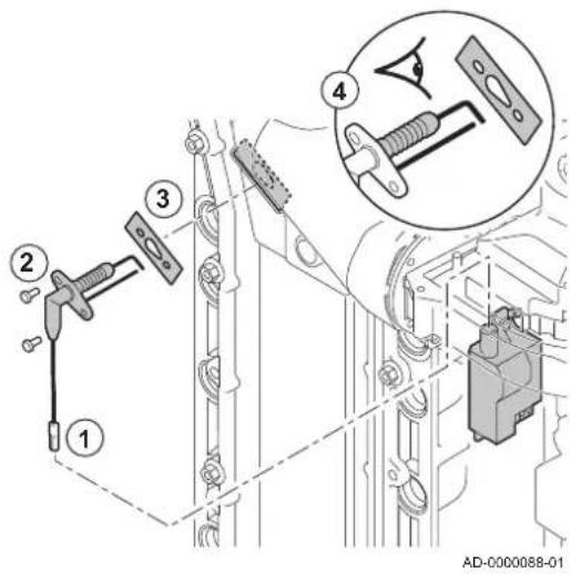
text_image
Technical diagram showing mechanical assembly steps with numbered components and a magnified inset of a component detail.The ionisation/ignition electrode must be replaced if:
• The ionisation current is < 4 μA.
• The electrode is damaged or worn.
• The electrode is included in the service kit.
- Remove the plug of the electrode from the ignition transformer.

Important
The ignition cable is fixed to the electrode and therefore may not be removed.
- Remove the two screws.
- Remove the entire component.
- Fit the new ionisation/ignition electrode.
- Reassemble the unit in the reverse order.
Fig.64 Checking the non-return valve
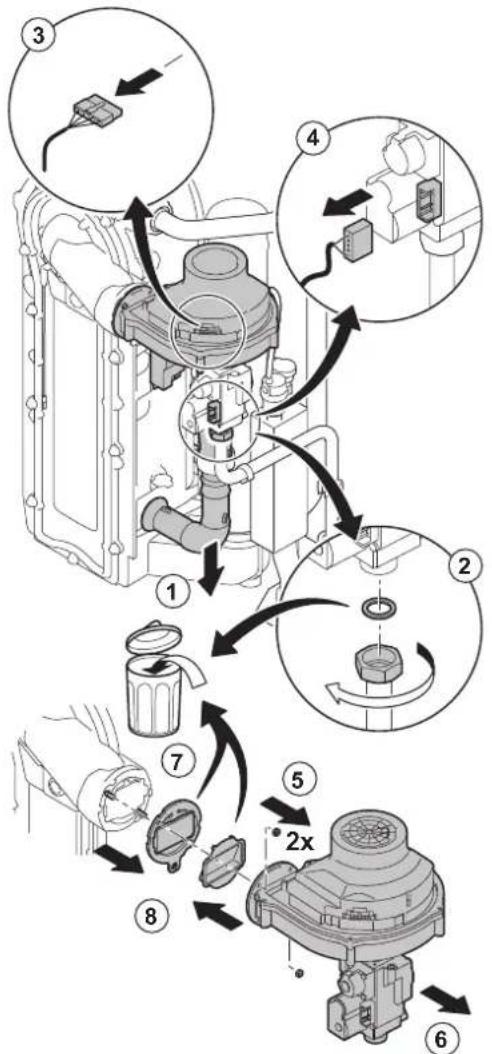
flowchart
graph TD
    A["Engine Component"] --> B["Assembly Module 1"]
    B --> C["Component 2"]
    C --> D["Component 3"]
    D --> E["Component 4"]
    E --> F["Component 5"]
    F --> G["Component 6"]
    G --> H["Component 7"]
    H --> I["Component 8"]
    I --> J["Assembly Module 8"]
    style A fill:#f9f,stroke:#333
    style B fill:#ccf,stroke:#333
    style C fill:#cfc,stroke:#333
    style D fill:#fcc,stroke:#333
    style E fill:#cff,stroke:#333
    style F fill:#ffc,stroke:#333
    style G fill:#cfc,stroke:#333
    style H fill:#fcc,stroke:#333
    style I fill:#ffc,stroke:#333
    style J fill:#fcc,stroke:#333
AD-3000342-01
10.4.2 Checking the non-return valve
- Remove the air inlet flue on the venturi.
- Loosen the gland on the gas valve unit.
- Remove the plug from the fan.
- Remove the plug from the gas valve unit.
- Dismantle the fan.
- Remove the fan together with the mixing elbow unit.
- Inspect the non-return valve and replace it in the event of a defect or damage, or if the maintenance kit contains a non-return valve.
- Reassemble in the reverse order.
10.4.3 Reassembling the boiler
- Fit all removed parts in the reverse order.

Caution
During inspection and maintenance operations, always replace all gaskets on the parts removed.
- Fill the siphon with water.
- Put the siphon back in place.
- Carefully open the water tap.
- Fill the installation with water.
- Vent the installation.
- Top up with more water if necessary.
- Check the tightness of the gas and water connections.
- Put the boiler back into operation.
11 Troubleshooting
11.1 Error codes
The boiler is fitted with an electronic regulation and control unit. The heart of the control is a microprocessor, the Comfort Master ^® , which both protects and controls the boiler. In the event of an error, a corresponding code is displayed.
The meaning of the error codes can be found in the error table.

Important Note the error code displayed. The error code is needed to find the cause of the error quickly and correctly and for any support from Remeha.
11.1.1 Blocking
A (temporary) blocking mode is a boiler status, resulting from an abnormal state. The display shows a blocking code (for example \$5The control unit makes a number of attempts to start the boiler again. The blocking codes can be read out as follows:
Fig.65 Blocking code
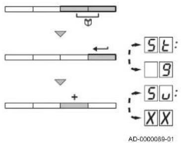
text_image
SET G SU XX AD-0000089-01-
Press the two keys at the same time.
-
Confirm by pressing key .← → The display alternates between S and the blocking code . :9
- Press the Key. → S up appears on the display.

Important The boiler automatically returns to operation once the cause of the blocking has been removed.
Tab.37 Blocking codes
| Blocking code Description | |
| SU:0 | Parameter error:• Parameter error on the PSU PCB:- Reset and DU- Restore parameters with Recom |
| SU:1 | Maximum flow temperature exceeded:• No flow or insufficient flow:- Check the flow (direction, pump, valves)- Reasons for the heat demand |
| SU:2 | Maximum increase of the flow temperature has been exceeded:• No flow or insufficient flow:- Check the flow (direction, pump, valves)- Check the water pressure- Check the cleanliness of the heat exchanger• Sensor error:- Check that the sensors are operating correctly- Check that the sensor has been fitted properly |
| Blocking code Description | |
| SU:7 | Maximum difference between the flow and return temperature exceeded:No flow or insufficient flow:Check the flow (direction, pump, valves)Check the water pressureCheck the cleanliness of the heat exchangerSensor error:Check that the sensors are operating correctlyCheck that the sensor has been fitted properly |
| SU:8 | No release signal:External cause: remove external causeParameter error: check parametersBad connection: check the wiring |
| SU:9 | Phase and neutral of mains supply mixed up:The mains connection is wired incorrectly: invert phase and neutralFloating network or 2-phase network: set parameter RH3 O |
| SU:10 | Blocking input is active:External cause: remove external causeParameter error: check parametersBad connection: check the wiring |
| SU:11 | Blocking input active or frost protection active:External cause: remove external causeParameter error: check parametersBad connection: check the wiring |
| SU:13 | Communication error with the SCU PCB:Bad connection with BUS: check the wiringSCU SCU PCB not present in boiler: carry out automatic detection |
| SU:14 | Water pressure too low:Water pressure too low:Check the water pressureFill the boiler and the installation with water |
| SU:15 | Gas pressure too low:No flow or insufficient flow:Check that the gas valve is fully openedCheck the gas supply pressureWrong setting of GPS gas pressure switch on the SCU PCB:Check whether the Gps has been correctly fittedReplace the Gps switch if necessary |
| SU:16(1) | Configuration error or SU PCB not recognised:Wrong SU PCB for this boiler: replace the SU PCB |
| SU:17(1) | Configuration error or default parameter table incorrect:Parameter error in the PCU PCB: replace the PCU PCB |
| SU:18(1) | Configuration error or PSU PCB not recognised:Wrong PCU PCB for this boiler: Replace the PCU PCB |
| SU:19(1) | Configuration error or parameters and unknown Reset and JF JU |
| SU:20(1) | Configuration procedure active:Active for a short time after switching on the boiler: no action |
| SU:21 | Communication error with the SU PCB:Bad connection: Check whether the PCU PCB has been correctly fitted in the connector on the SU PCB |
| SU:22 | No flame during operation:• No ionisation current:- Vent the gas supply to remove air- Check that the gas valve is fully opened- Check the gas supply pressure- Check the operation and setting of the gas valve unit- Check that the air supply inlet and flue gas outlet are not blocked- Check that there is no recirculation of flue gases |
| SU:25 | SU PCB internal fault: replace the SU PCB |
| (1) These blocks are not stored in the error memory | |
11.1.2 Lock out
If the blocking conditions still exist after various start attempts, the boiler goes into lockout (also called error). The boiler will also lock out if an error is signalled anywhere in the boiler. An error code will appear on the display. The error code is displayed as follows:
In a red flashing display:
- the symbol
- the symbol RESET
- the error code, for example E:01
The meaning of the error codes can be found in the error table. Note the error code.

Important
The error code is needed to find the cause of the error quickly and correctly and for any support from Remeha.
Press the RESET for two seconds. If the error code continues to display, search for the cause in the error table and apply the solution.

Important
If the display does not show RESET rather, the boiler must be switched off and then switched on again 10 seconds later before the error can be reset.
Tab.38 Error codes
| Error code Description | |
| E:00 | Parameter storage unit PSU not found:Bad connection: check the wiring |
| E:01 | Safety parameters not OK:Bad connection: check the wiringFaulty PSU: replace PSU |
| E:02 | Flow temperature sensor short circuited:Bad connection: check the wiringSensor not connected or incorrectly connected:- Check that the sensor has been fitted properly- Check that the sensors are operating correctlyFaulty sensor: replace the sensor if necessary |
| E:03 | Flow temperature sensor open:Bad connection: check the wiringSensor not connected or incorrectly connected:- Check that the sensor has been fitted properly- Check that the sensors are operating correctlyFaulty sensor: replace the sensor if necessary |
| Error code Description | |
| E:04 | Temperature of heat exchanger too low:Bad connection: check the wiringSensor not connected or incorrectly connected:- Check that the sensors are operating correctly- Check that the sensor has been fitted properlyFaulty sensor: replace the sensor if necessaryNo circulation:- Vent the air from the CH system- Check the circulation (direction, pump, valves)- Check the water pressure- Check the cleanliness of the heat exchanger- If present: check the boiler type parameter setting |
| E:05 | Temperature of heat exchanger too high:Bad connection: check the wiringSensor not connected or incorrectly connected:- Check that the sensors are operating correctly- Check that the sensor has been fitted properlyFaulty sensor: replace the sensor if necessaryNo circulation:- Vent the air from the CH system- Check the circulation (direction, pump, valves)- Check the water pressure- Check the cleanliness of the heat exchanger- If present: check the boiler type parameter setting |
| E:06 | Return temperature sensor short-circuited:Bad connection: check the wiringSensor not connected or incorrectly connected:- Check that the sensors are operating correctly- Check that the sensor has been fitted properlyFaulty sensor: replace the sensor if necessary |
| E:07 | Open circuit in return temperature sensor:Bad connection: check the wiringSensor not connected or incorrectly connected:- Check that the sensors are operating correctly- Check that the sensor has been fitted properlyFaulty sensor: replace the sensor if necessary |
| E:08 | Return temperature too low:Bad connection: check the wiringFaulty sensor: replace the sensor if necessarySensor not connected or incorrectly connected:- Check that the sensors are operating correctly- Check that the sensor has been fitted properlyNo circulation:- Vent the air from the CH system- Check the circulation (direction, pump, valves)- Check the water pressure- Check the cleanliness of the heat exchanger- If present: check the boiler type parameter setting |
| E:09 | Return temperature too high:Bad connection: check the wiringFaulty sensor: replace the sensor if necessarySensor not connected or incorrectly connected:- Check that the sensors are operating correctly- Check that the sensor has been fitted properlyNo circulation:- Vent the air from the CH system- Check the circulation (direction, pump, valves)- Check the water pressure- Check the cleanliness of the heat exchanger- If present: check the boiler type parameter setting |
| E:10E:11 | Difference between the flow and return temperatures too great:No circulation:- Vent the air from the CH system- Check the circulation (direction, pump, valves)- Check the water pressure- Check the cleanliness of the heat exchanger- Check that the heating pump is operating correctly- If present: check the boiler type parameter settingSensor not connected or incorrectly connected:- Check that the sensors are operating correctly- Check that the sensor has been fitted properlyFaulty sensor: replace the sensor if necessary |
| E:12 | Temperature of heat exchanger above normal range (STB high-limit thermostat):- Bad connection: check the wiringSensor not connected or incorrectly connected:Check that the sensors are operating correctlyCheck that the sensor has been fitted properly-Faulty sensor: replace the sensor if necessary- No circulation:Vent the air from the CH systemCheck the circulation (direction, pump, valves)Check the water pressureCheck the cleanliness of the heat exchangerIf present: check the boiler type parameter settingIf present: Air pressure differential switch has been triggered:- Air supply or flue gas outlet blocked: check air supply and flue gas outlet for blockage |
| E:14 | Five failed burner starts:No ignition spark:- Check cabling of ignition transformer- Check the ionisation/ignition electrode- Check breakdown to earth- Check the condition of the burner cover- Check the earthing- Defective control SU PCBIgnition spark but no flame:- Vent the gas supply to remove air- Check that the gas valve is fully opened- Check the gas supply pressure- Check the operation and setting of the gas valve unit- Check that the air supply inlet and flue gas outlet are not blocked- Check the wiring on the gas valve unit- Defective control SU PCBFlame present, but ionisation has failed or is inadequate:- Check that the gas valve is fully opened- Check the gas supply pressure- Check the ionisation/ignition electrode- Check the earthing- Check the wiring on the ionisation/ignition electrode |
| E:15 | If VPS switch is present: 5 failed gas leakage checks:Gas pressure non-existent or too low:check whether the gas tap is properly opencheck the gas supply pressureWiring fault: check the wiringIncorrect setting of the VPS switch: check whether the VPS switch is set properlyVPS pressure switch not installed or poorly installed: check that the VPS switch is properly installedFaulty VPS switch: replace VPS switch if necessaryFaulty gas valve: check the gas valve and replace it if necessary |
| E:16 | False flame signal:Ionisation current measured but no flame should be present: check the ionisation and ignition electrodeIgnition transformer faulty: replace the ignition transformer if necessaryFaulty gas valve: check the gas valve and replace it if necessaryThe burner remains very hot: O_2/CO_2 too high: adjust O_2/CO_2 settings |
| E:17 | Gas valve error in SU PCB:Bad connection: check the wiringDefective SU PCB: check the SU PCB and replace if necessary |
| E:34 | Fan operation error:Bad connection: check the wiringFan defective:- Check for adequate draw on the chimney connection- Replace the fan if necessary |
| E:35 | Flow and return reversed:Bad connectionSensor not connected or incorrectly connected:Check that the sensors are operating correctly- Check that the sensor has been fitted properlySensor failure: Replace the sensor if necessaryWater circulation in wrong direction: check the circulation (direction, pump, valves) |
| E:36 | 5x flame loss:No ionisation current:Vent the gas supply to remove airCheck that the gas valve is fully openedCheck the gas supply pressureCheck the operation and setting of the gas valve unitCheck that the air supply inlet and flue gas outlet are not blockedCheck that there is no recirculation of flue gases |
| E:37 | Error in communication with SU PCB:Bad connection: check whether the SU PCB has been correctly fitted in the connector on the PCU PCB |
| E:38 | Communication error with the SCU PCB:Bad connection: check the wiringFaulty SCU PCB: replace SCU PCB |
| E:39 | Blocking input in locked-out mode:Bad connection: check the wiringExternal cause: remove external causeWrong parameter set: check the parameters |
| E:40 | If present: Heat recovery unit test fault:Bad connection: check the wiringExternal cause: remove external causeWrong parameter set: check the parameters |
11.2 Error memory
The boiler control unit has an error memory. It stores the last 16 errors that have occurred.
In addition to the error codes, the following data is also saved:
• Number of times that the error occurred: (a). □:XXXX
- Boiler operating mode (\$T:xxx
- The flow temperature (T and the return temperature ( ) when the error occurred.
T2:××
To view the error memory, you must first enter the access code 0012
Fig.66 Reading out an error
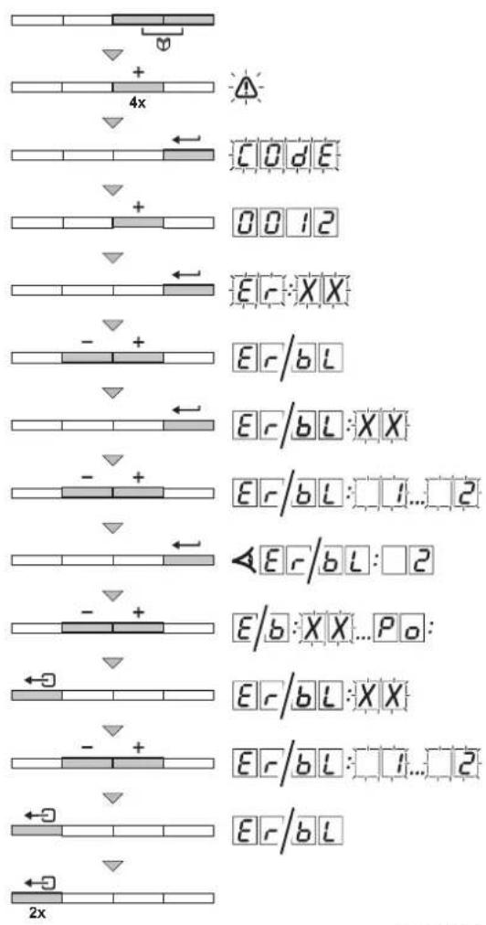
text_image
4x CODE 0012 Er:XX - + Er/bL Er/bL:XX - + Er/bL:1...2 - + Er/bL:2 - + Er/b:XX...Po: Er/bL:XX - + Er/bL:1...2 Er/bL 2xAD-0000090-01
11.2.1 Reading out the error memory
- Press the two keys at the same time and then press the key until the symbol flashes in the menu bar.
- Select the installer menu using the key. → CODE appears on the display.
- Use the ☐ keys to set the installer code . 0012
- To confirm, press the key. ⇒ ER:XXXX appears on the display.
- The error list or blocking list can be displayed by pressing the - key.
- Confirm by pressing the key. ⇒ ER: X X appears with a flashing last error that occurred, e.g. □.2
- Use the or keys to scroll through the errors or blocks.
- Press the key to display the details of the errors or blocks.
- Press the or key to view the following data:
-_1:1=Number of times that the error occurred.
- HR = Number of operating hours.
- 5T = Status.
- 5u = Sub-status.
- 1 = Flow temperature (°C).
- T2 = Return temperature (°C).
- T3 = Calorifier temperature (°C).
- T4 = Outside temperature (°C). Only if an outside temperature sensor is connected (accessory)
- T5 = Solar boiler temperature (°C).
- SP = Internal set point (°C).
- = Ionisation current ( A ).
- = Fan speed (rpm).
- PR = Water pressure (bar).
- P_o = Supplied relative heat output (%).
- Press the key to interrupt the display cycle.
⇒ ER: X X appears with a flashing 求X last error that occurred.
- Use the or keys to scroll through the errors or blocks.
- Press the key to show the error list or blocking list.
- Press the key twice to exit the error menu.
Fig.67 Clearing error memory
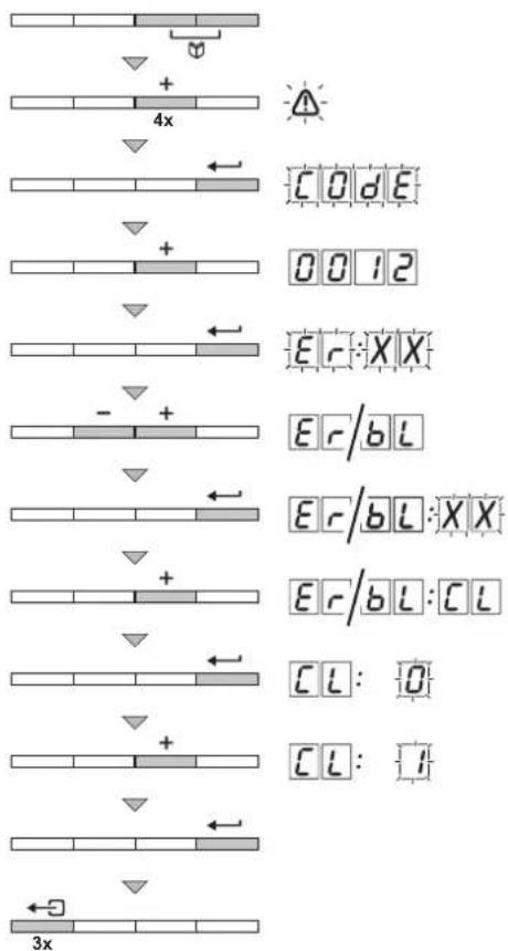
text_image
+ 4x CODE 0012 Er:XX - + Er/bL Er/bL:XX Er/bL:CL CL:0 CL:1 3xAD-0000091-01
11.2.2 Clearing error memory
-
Press the two keys at the same time and then press the key until the symbol flashes in the menu bar.
-
Select the installer menu using the key. → CODE appears on the display.
-
Use the or keys to set the installer code . 0012
-
To confirm, press the key. ⇒ ER:XX appears on the display.
-
The error list or blocking list can be displayed by pressing the ☑ key.
-
Confirm by pressing the key. ⇒ ER:XX appears with a flashing XX
-
Press the key several times until appears on the display.
-
Press the key. ⇒ [CL:O] appears with a flashing O
-
Press the key to adjust the setting to . 1
-
Press the key to delete the errors from the error memory.
-
Press the key three times to exit the error memory.
12 Disposal
12.1 Removal/recycling

Important
Removal and disposal of the boiler must be carried out by a qualified person in accordance with local and national regulations.
To remove the boiler, proceed as follows:
- Switch off the boiler's electrical connection.
- Shut off the gas supply.
- Shut off the water supply.
- Drain the installation.
- Remove the siphon.
- Remove the air supply/flue gas outlet pipes.
- Disconnect all pipes on the boiler.
- Remove the boiler.
13 Spare parts
13.1 General
Only replace defective or worn boiler parts with original parts or recommended parts.
Send the part to be replaced to the Remeha Quality Control department if the relevant part is covered by the guarantee (see the General Terms of Sale and Delivery).
13.2 Parts
Fig.68 Quinta Pro 30 - 45
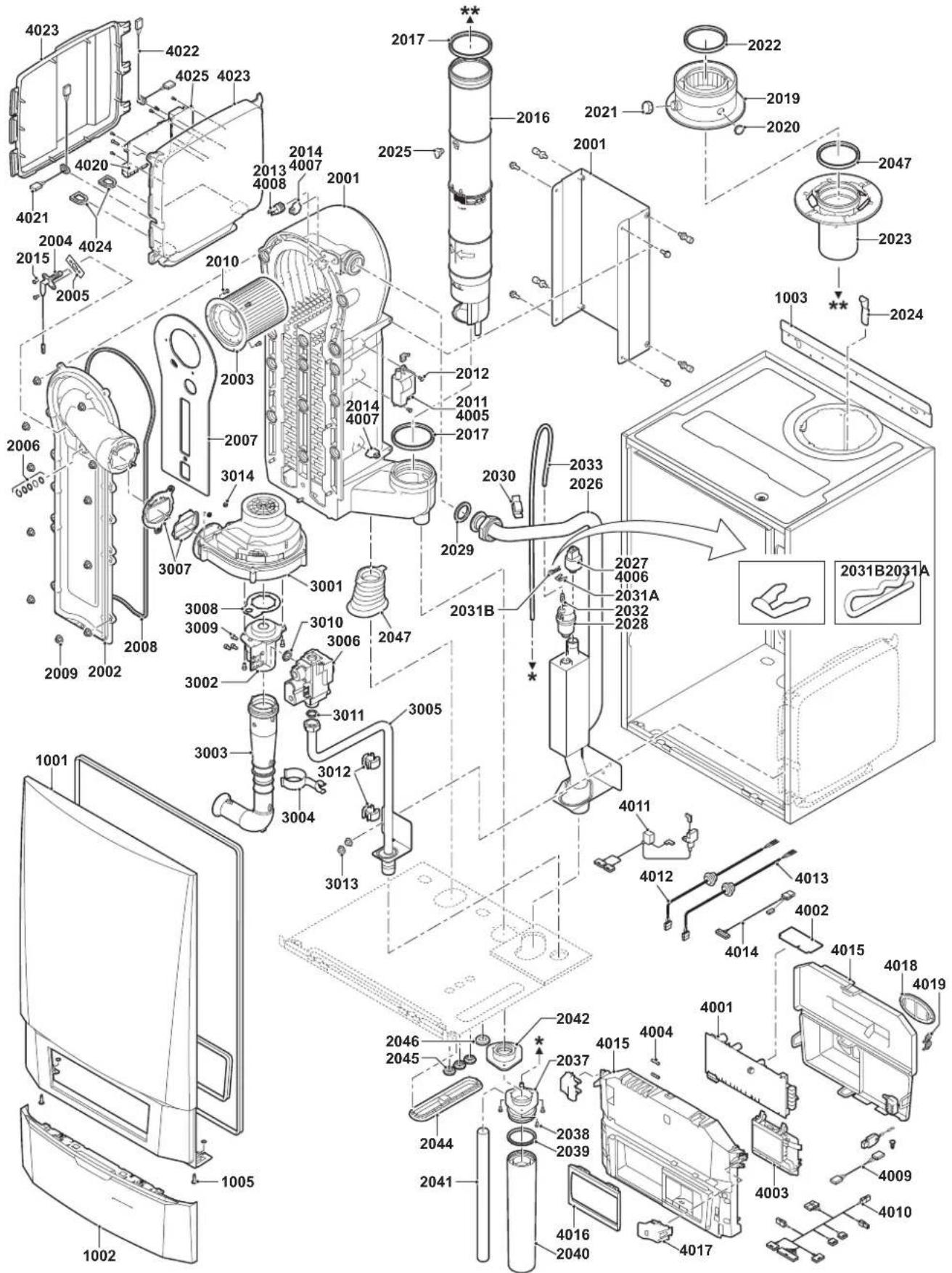
text_image
Exploded view diagram of a washing machine with numbered components and assembly detailsEV 90552-1-4
AD-0800023-03
Fig.69 Quinta Pro 55 - 65
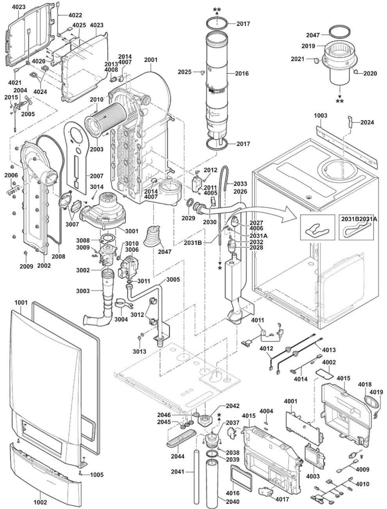
text_image
Exploded view diagram of a refrigerator assembly with numbered components and labeled partsEV 90553-1-4
AD-0800028-03
Fig.70 Quinta Pro 90
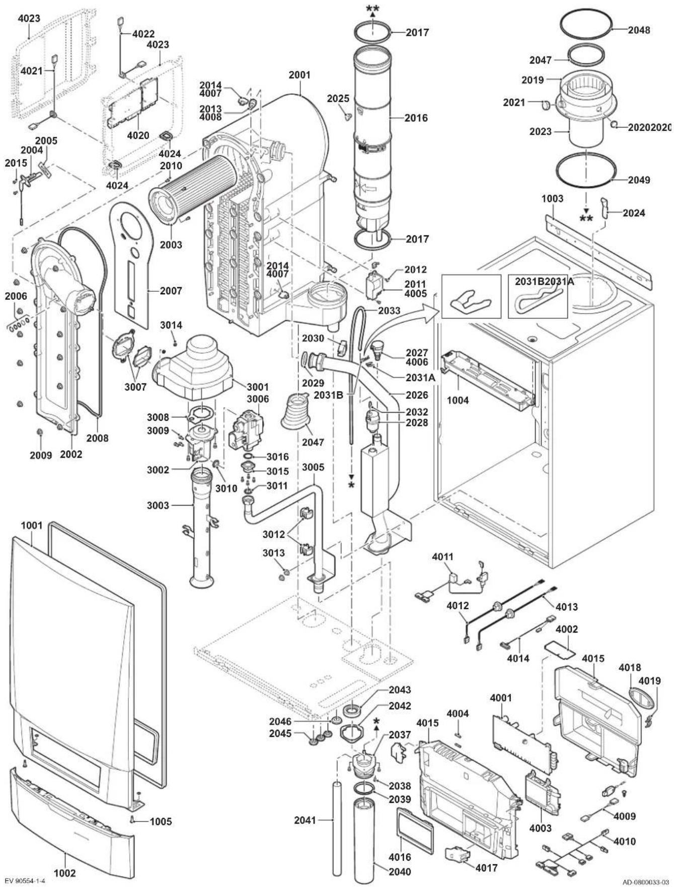
text_image
Exploded view diagram of a washing machine with numbered components and assembly detailsFig.71 Quinta Pro 115
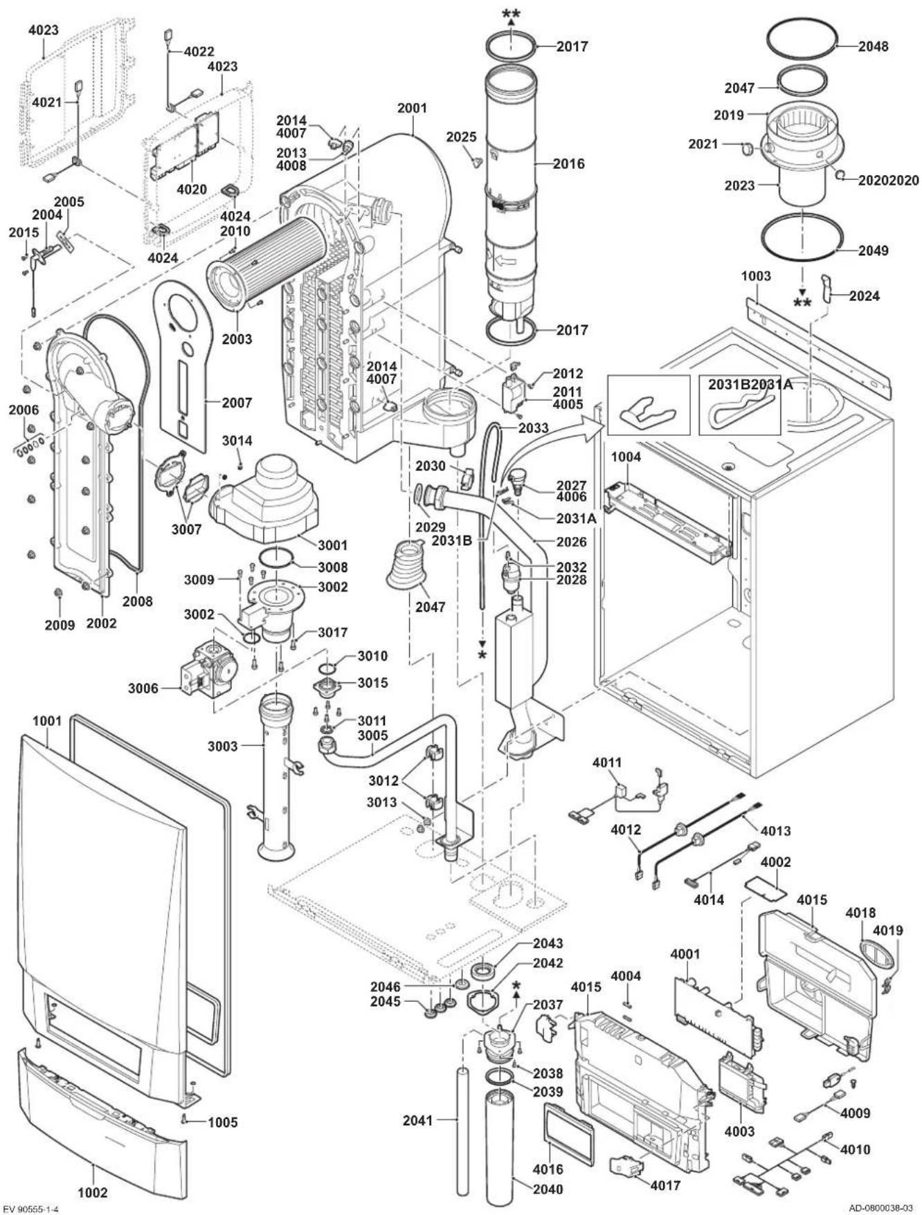
text_image
Exploded view diagram of a washing machine with numbered components and assembly details14 Appendix
14.1 ErP information
| Remeha - Quinta Pro 30 45 55 65 90 115 | |||||||
| Seasonal space heating energy efficiency class | A | A | A | A | - | - | |
| Rated heat output (Prated or Psup) | kW 30 41 55 62 84 107 | ||||||
| Seasonal space heating energy efficiency % 94 94 93 94 -- | |||||||
| Annual energy consumption GJ 91 124 171 187 | -- | ||||||
| Sound power level L_WA indoors | dB | 46 53 53 53 60 59 | |||||

See
For specific precautions about assembling, installing and maintaining: Safety, page 6
14.1.2 Package sheet
Fig.72 Package sheet for boilers indicating the space heating energy efficiency of the package
| Seasonal space heating energy efficiency of boiler | |
| Temperature control from fi che of temperature control | Class I = 1%, Class II = 2%, Class III = 1.5%, Class IV = 2%, Class V = 3%, Class VI = 4%, Class VII = 3.5%, Class VIII = 5% |
| Supplementary boiler from fi che of boiler | Seasonal space heating energy efficiency (in %) |
| Solar contribution from fi che of solar device (‘III’ x + ‘IV’ x ) x 0.9 x (/100) x = + | Tank rating (1) A* = 0.95, A = 0.91, B = 0.86, C = 0.83, D - G = 0.81 |
| Supplementary heat pump from fi che of heat pump | Seasonal space heating energy efficiency (in %) |
| Solar contribution AND Supplementary heat pump select smaller value | 0.5 x OR 0.5 x = - |
| Seasonal space heating energy efficiency of package | |
| Seasonal space heating energy efficiency class of package | |
| Boiler and supplementary heat pump installed with low temperature heat emitters at 35°C? from fi che of heat pump | 7 |
The energy efficiency of the package of products provided for in this fiche may not correspond to its actual energy efficiency once installed in a building, as this efficiency is influenced by further factors such as heat loss in the distribution system and the dimensioning of the products in relation to building size and characteristics.
AD-3000743-01
I The value of the seasonal space heating energy efficiency of the preferential space heater, expressed in %.
II The factor for weighting the heat output of preferential and supplementary heaters of a package as set out in the following table. III The value of the mathematical expression: 294/(11 · Prated), whereby ‘Prated’ is related to the preferential space heater. IV The value of the mathematical expression 115/(11 · Prated), whereby ‘Prated’ is related to the preferential space heater.
Tab.40 Weighting of boilers
| Psup / (Prated + Psup)^(1)(2) | II, package without hot water storage tank II, | package with hot water storage tank |
| 0 0 0 | ||
| 0.1 0.3 0.37 | ||
| 0.2 0.55 0.70 | ||
| 0.3 0.75 0.85 | ||
| 0.4 0.85 0.94 | ||
| 0.5 0.95 0.98 | ||
| 0.6 0.98 1.00 | ||
| ≥ 0.7 1.00 1.00 | ||
| (1) The intermediate values are calculated by linear interpolation between the two adjacent values.(2) Prated is related to the preferential space heater or combination heater. | ||
14.2 EC declaration of conformity
The unit complies with the standard type described in the EC declaration of conformity. It has been manufactured and commissioned in accordance with European directives.
The original declaration of conformity is available from the manufacturer.
14.3 Optional electrical connections
© Copyright
All technical and technological information contained in these technical instructions, as well as any drawings and technical descriptions supplied, remain our property and shall not be multiplied without our prior consent in writing. Subject to alterations.
T +44 (0)118 978 3434
F +44 (0)118 978 6977
E boilers@remeha.co.uk
Remeha Commercial UK
Innovations House
3 Oaklands Business Centre
Oaklands Park
RG41 2FD Wokingham

OpenTherm®


PART OF BDR THERMEA