
IP7131 - Security Camera Vivotek - Free user manual and instructions
Find the device manual for free IP7131 Vivotek in PDF.


User questions about IP7131 Vivotek
0 question about this device. Answer the ones you know or ask your own.
Ask a new question about this device
Download the instructions for your Security Camera in PDF format for free! Find your manual IP7131 - Vivotek and take your electronic device back in hand. On this page are published all the documents necessary for the use of your device. IP7131 by Vivotek.
USER MANUAL IP7131 Vivotek
natural_image
White and black Vivotek camera with lens, no visible text or symbols on bodyProduct Name: Network Camera (IP7131)
Release Date: 2009/05/13
Manual Revision: 2.2
Web Site: www.vivotek.com
Email: technical@vivotek.com
sales@vivotek.com
Made in Taiwan. © 2007-2009 VIVOTEK INC. All rights reserved
Before You Use This Product
The use of surveillance devices may be prohibited by law in your country. The Network Camera is not only a high-performance web-ready camera but also can be part of a flexible surveillance system. It is the user's responsibility to ensure that the operation of such devices is legal before installing this unit for its intended use.
It is important to first verify that all contents received are complete according to the list in the "Package Contents" chapter. Take notice of the warnings in "Quick installation guide" before the Network Camera is installed, then carefully read and follow the instructions in the "Installation" chapter to avoid damages due to faulty assembly and installation. This also ensures the product is used properly as intended.
The Network Camera is a network device and its use should be straightforward for those who have basic network knowledge. The "Troubleshooting" chapter in the Appendix provides remedies to the most common errors in set up and configuration. You should consult this chapter first if you run into a system error.
The Network Camera is designed for various applications including video sharing, general security/surveillance, etc. The "How to Use" chapter suggests ways to best utilize the Network Camera and ensure proper operations. For the creative and professional developers, the "URL Commands of The Network Camera" chapter serves to be a helpful reference to customize existing homepages or integrating with the current web server.
For paragraphs preceded by ⚠ the reader should use caution to understand completely the warnings. Ignoring the warnings may result in serious hazards or injuries.
Table of Contents
Before You Use This Product....2
Package Contents ....6
Installation 7
Hardware installation....7
Software installation....8
Initial Access to the Network Camera....9
Check Network Settings 9
Add Password to prevent Unauthorized Access....9
How to Use 10
Authentication.... 10
Installing plug-in.... 11
Primary user's capability 12
Main Screen with Camera View 12
Digital Zoom 13
Snapshot.... 13
Client settings.... 14
Administrator's capability 17
Fine-tuning for Best Performance.... 17
Opening accounts for new users 20
Build a security application 21
Software revision upgrade 22
Definitions in Configuration 23
System parameters 25
Security settings.... 26
Network settings.... 27
Network type 27
HTTP 28
RTSP Streaming 28
DDNS.... 30
Access List 31
Audio and Video.... 32
General 32
Video Settings.... 32
Video orientation 32
Audio settings 33
Image Settings 34
Email & FTP 35
Email 35
FTP 35
Motion detection 37
Application settings 38
Snapshot.... 38
Weekly schedule.... 39
Snapshot file name prefix 39
Send out the snapshot while motion detection 39
Sequential operation 40
Method for sending snapshot.... 40
System log.... 47
Viewing system parameters.... 48
Maintenance.... 49
Appendix.... 50
A. Troubleshooting 50
Status LED 50
Reset and restore 50
B. URL commands of the Network Camera.... 51
Get server parameter values 51
Set server parameter values 52
Available parameters on the server 54
Application page CGI command 64
Capture single snapshot 65
Account management 66
System logs.... 67
Configuration file 68
Upgrade firmware.... 68
C. Technical specifications .... 70
Package Contents
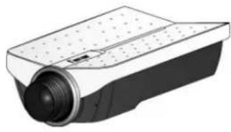
IP7131
natural_image
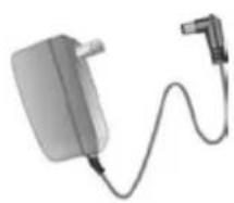
Illustration of a camera lens mounted on a rectangular base (no text or symbols visible)Power adapter
natural_image
Illustration of a connected electrical plug with a cable (no text or symbols visible)Camera stand

Software CD

text_image
VIVOTEK Extend Your View Secure Your Life Software CDQuick installation guide

text_image
3GFP Network Camera Multi-language Quick Guide VIVOTEK P7131 The guide is also called by the manufacturer's brand. If named information is directed to the main author.Warranty card
text_image
Technical document section titled 'HARDWARE LIMITED WARRANTY WRITTEN' detailing warranty requirements and specifications for a company's rights issue.Installation
In this manual, "User" refers to whoever has access to the Network Camera, and "Administrator" refers to the person who can configure the Network Camera and grant user access to the camera.
Hardware installation
text_image
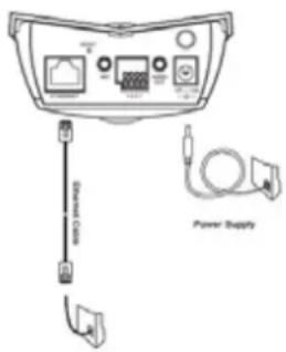
Power SupplyPlease verify that your product package contains all the accessories listed in the foregoing Package Contents. Depending on the user's application, an Ethernet cable may be needed. The Ethernet cable should meet the specs of UTP Category 5 and not exceed 100 meters in length.
Connect the power adapter jack to the Network Camera before plugging in to the power socket. This will reduce the risk of accidental electric shock.
| Status LED Color | Description |
| Blinking red | Power is being supplied to the camera. |
| Solid green | The camera is booting up. |
| Solid green with blinking red in between | The camera is trying to obtain an IP address. |
| Solid green and red | An IP address is successfully assigned to the camera. |
| Solid red with blinking green in between | The camera is working. |
| Blinking red and green | During firmware upgrading |
To install in Ethernet
Make sure the Ethernet is firmly connected to a switch hub. After attaching the Ethernet cable plug in the power adapter. When the red LED is lighted and the green LED blinks every other second in between, indicating the camera is working, please go to next paragraph "Software installation". If the Ethernet is not available, Network Camera will switch to wireless LAN mode.
This Network Camera provides a general I/O terminal block with one digital input and one digital output device control. The pin definition is as below.
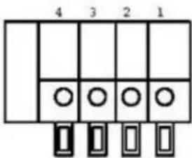
text_image
4 3 2 1 ◯◯◯◯- Digital output
- Digital input
- DC power
- Ground
Software installation
At the end of the hardware installation, users can use Installation Wizard program included in the product CDROM to find the location of the Network Camera. There may be many Network Cameras in the local network. Users can differentiate the Network Cameras with the serial number. The serial number is printed on the labels on the carton and the back of the Network Camera body. Please refer to the user's manual of Installation Wizard for detail.
Once installation is complete, the Administrator should proceed to the next section "Initial access to the Network Camera" for necessary checks and configurations.
Initial Access to the Network Camera
Check Network Settings
The Network Camera can be connected either before or immediately after software installation onto the Local Area Network. The Administrator should complete the network settings on the configuration page, including the correct subnet mask and IP address of gateway and DNS. Ask your network administrator or Internet service provider for the detail information. By default the Network Camera requires the Administrator to run installation every time it reboots. If the network settings are to remain unchanged, disable the Install option. Refer to “Network settings” on the System Configuration page for details. If any setting is entered incorrectly and cannot proceed to setting up the Network Camera, restore the factory settings following the steps in the “Troubleshooting” chapter of the Appendix.
Add Password to prevent Unauthorized Access
The default Administrator's password is blank and the Network Camera initially will not ask for any password. The Administrator should immediately implement a new password as a matter of prudent security practice. Once the Administrator's password is saved, the Network Camera will ask for the user's name and password before each access. The Administrator can set up a maximum of twenty (20) user accounts. Each user can access the Network Camera except to perform system configuration. Some critical functions are exclusive for the Administrator, such as system configuration, user administration, and software upgrades. The user name for the Administrator is permanently assigned as "root". Once the password is changed, the browser will display an authentication window to ask for the new password. Once the password is set, there is no provision to recover the Administrator's password. The
only option is to restore to the original factory default settings.
How to Use
Authentication
After opening the Web browser and typing in the URL of the Network Camera, a dialogue window pops up to request a username and password. Upon successful authentication, the following figure is displayed.
The foreground is the login window and the background shows the message if authentication fails. The user may check the option box to save the password for future convenience. This option is not available to the Administrator for obvious reason.
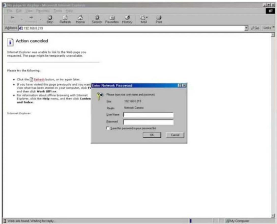
text_image
No pages to display - Microsoft Internet Explorer File Edit View Favorites Daily Help Address 192.168.0.219 Go Links Action canceled Internet Explorer was unable to link to the Web page you requested. The page might be temporarily unavailable. Please try the following: • Click the Refresh button, or try again later. • If you have visited this page previously and you want view what has been stored on your computer, click F1 and then click Work offline. • For information about offline browsing with Internet Explorer, click the Help menu, and then click Content and Index. Enter Network Password Please type your user name and password Size 192.168.0.219 Plugins Network Camera User Name: Password: Save this password in your password list OK Cancel Internet Explorer Web site found. Waiting for reply. My ComputerInstalling plug-in
For the initial access to the Network Camera in Windows, the web browser may prompt for permission to install a new plug-in for the Network Camera. Permission request depends on the Internet security settings of the user's PC or notebook. If the highest security level is set, the computer may prohibit any installation and execution attempt. This plug-in has been registered for certificate and is used to display the video in the browser. Users may click on Yes to proceed. If the web browser does not allow the user to continue to install, check the Internet security option and lower the security levels or contact your IT or networking supervisor for help.
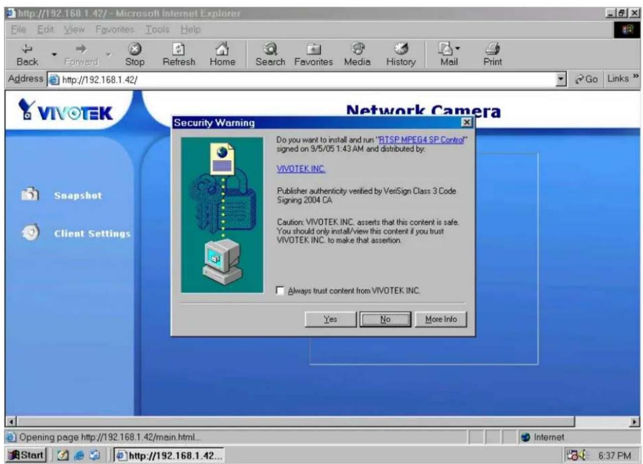
text_image
http://192.168.1.42/ - Microsoft Internet Explorer File Edit View Favorites Tools Help Back Forward Stop Refresh Home Search Favorites Media History Mail Print Address http://192.168.1.42/ Go Links VIVOTEK Network Camera Security Warning Do you want to install and run "RTSP MPEG4 SP Control" signed on 9/5/05 1:43 AM and distributed by: VIVOTEK INC. Publisher authenticity verified by VeriSign Class 3 Code Signing 2004 CA Caution: VIVOTEK INC. asserts that this content is safe. You should only install/view this content if you trust VIVOTEK INC. to make that assertion. Always trust content from VIVOTEK INC. Yes No More Info Snapshot Client Settings Opening page http://192.168.1.42/main.html... Start http://192.168.1.42... 6:37 PMPrimary user's capability
Main Screen with Camera View
The main page layout has two parts:
Configuration functions: The camera can be configured using these user interfaces.
Camera View: What the camera sees.
Click on the configuration link to the left of the image window to enter the configuration page.
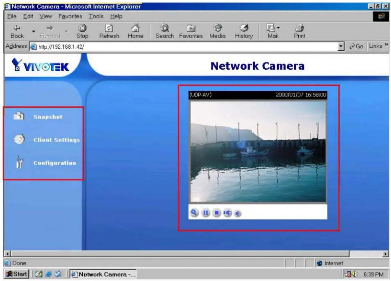
text_image
Network Camera - Microsoft Internet Explorer File Edit View Favorites Tools Help Back Forward Stop Refresh Home Search Favorites Media History Mail Print Address http://192.168.1.42/ Go Links VIVOTEK Network Camera (SDP-AV) 2000/01/07 16:58:00 Snapshot Client Settings Configuration Done Start Network Camera -... 6:39 PMDigital Zoom
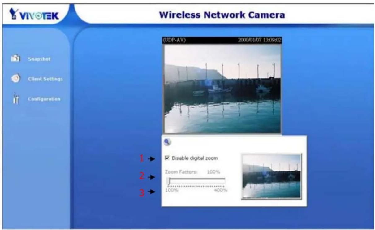
Click on the magnifier icon under the camera view then the digital zoom control panel will be shown. Uncheck "Disable digital zoom" and use the slider control to change the zoom factors.
text_image
VIVOTEK Wireless Network Camera (UDP-AV) 2000/01/07 13:09:02 Snapshot Client Settings Configuration 1 → 2 → 3 → Disable digital zoom Zoom Factors: 100% 100% 400%Snapshot
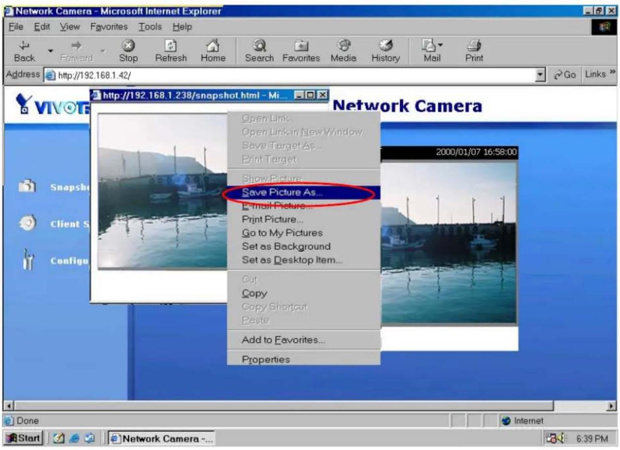
Click on "Snapshot", web browser will pop up a new window to show the snapshot. Users can point at the snapshot and click the right button of mouse to save it.
text_image
Network Camera - Microsoft Internet Explorer File Edit View Favorites Tools Help Back Forward Stop Refresh Home Search Favorites Media History Mail Print Address http://192.168.1.42/ Go Links VIVOTF http://192.168.1.238/snapshot.html - Mi... Open Link Open Link in New Window Save Target As... Print Target Show Picture... Save Picture As... E-mail Picture... Print Picture... Go to My Pictures Set as Background Set as Desktop Item... Cut Copy Copy Shortout Paste Add to Favorites... Properties 2000/01/07 16:58:00 Snapsh Client S Configu Done Start Network Camera - ... Internet 6:39 PMClient settings
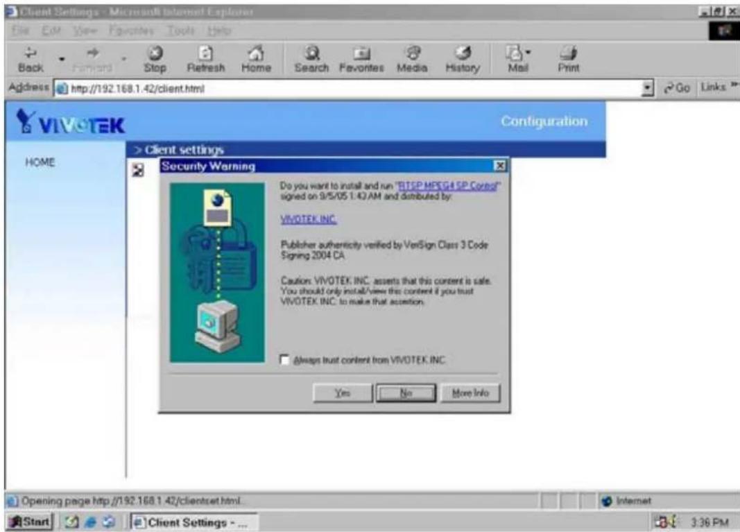
At the initial access to the "Connection type" page in Windows, the web browser will ask for a new plug-in installation, the plug-in being the Network Camera. This plug-in has been registered for certification and can be used to change the parameters at the client's site. The user may click on Yes to install the plug-in. If the web browser does not allow the user to complete the installation, check the Internet security to lower the security level or contact your IT or networking supervisor.
text_image
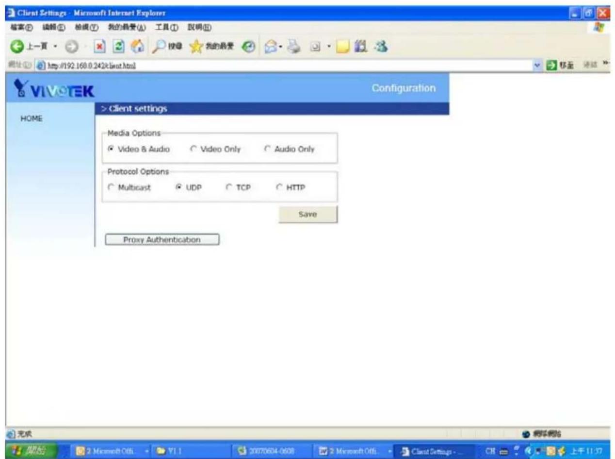
Client Settings - Microsoft Internet Explorer File Edit View Favorites Tools Help Back Forward Stop Refresh Home Search Favorites Media History Mail Print Address http://192.168.1.42/client.html VIVOTEK Configuration GO Links HOME > Client settings Security Warning Do you want to install and run "RISP MPEG4 SP Coreo" signed on 9/5/05 1:40 AM and distributed by: VIVOTEK INC. Publisher authenticity verified by VeriSign Class 3 Code Signing 2004 CA Caution: VIVOTEK INC. asserts that this content is safe. You should only install/view this content if you trust VIVOTEK INC. to make that accention. Always trust content from VIVOTEK INC. Yes No More Info Opening page http://192.168.1.42/clientset.html. Internet Start Client Settings - ... 3:36 PMThere are two settings for the client side. One is "Media Options" for users to determine the type of media to be streaming. The other is "Protocol Options" which allows choices on connection protocol between client and server. There are two protocols choices to optimize your usage – UDP and TCP.
The UDP protocol allows for more real-time audio and video streams. However, some packets may be lost due to network burst traffic and images may be obscured.
The TCP protocol allows for less packet loss and produces a more accurate video display. The downside with this protocol is that the real-time effect is worse than that with the UDP protocol.
If no special need is required, UDP protocol is recommended. Generally speaking, the client's choice will be in the order of UDP → TCP. After the Network Camera is connected successfully, "Protocol Option" will indicate the selected protocol. The selected protocol will be recorded in the user's PC and will be used for the next connection. If the network environment is changed, or the user wants to let the web browser to detect again, manually select the UDP protocol, save, and return HOME to
re-connect.
text_image
Client Settings - Microsoft Internet Explorer 檔案(E) 編輯(E) 檢報(Y) 我的最愛(A) 工具(T) 說明(D) 上一頁 網址(O) http://192.168.0.242k最佳.html VIVO EK Configuration HOME > Client settings Media Options Video & Audio Video Only Audio Only Protocol Options Multicast UDP TCP HTTP Save Proxy Authentication 完成 開始 Microsoft Offs YI 1 20070604-0608 Microsoft Offs Client Settings - CH 上午 11:37Digital output
Click on "ON", the digital output of the Network Camera will be triggered. Or, Clicking on "OFF" can let the digital output turn into normal state.
Administrator's capability
Fine-tuning for Best Performance
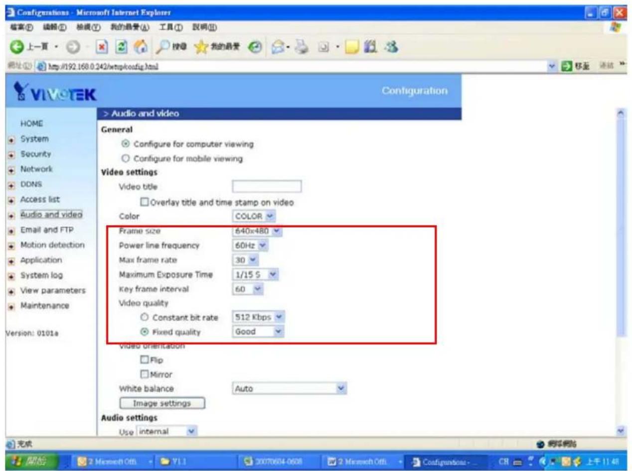
Best performance generally equates to the fastest image refresh rate with the best video quality, and at the lowest network bandwidth as possible. The three factors, "Maximum frame rate", "Constant bit rate", and "Fix quality" on the Audio and Video Configuration page, are correlative to allow for achieving the best performance possible.
text_image
Configurations - Microsoft Internet Explorer 檔案(F) 編輯(E) 檢報(Y) 我的最愛(A) 工具(T) 說明(N) 上一頁 http://192.168.0.242/mspkconfig.html 移至 選續 VIVO TEK Configuration > Audio and video General Configure for computer viewing Configure for mobile viewing Video settings Video title Overlay title and time stamp on video Color COLOR Frame size 640x480 Power line frequency 60Hz Max frame rate 30 Maximum Exposure Time 1/15 S Key frame interval 60 Video quality Constant bit rate 512 Kbps Fixed quality Good Video orientation Flip Mirror White balance Auto Image settings Audio settings Use internal 完成 開始 2 March Off 71 1 20070604-0608 2 March Off Configurations - CR 上午 11:48For Viewing by Mobile Phone
Most 3GPP cell phone supports media streaming with MPEG4 video and GSM-AMR audio. Due to the limitation of the bandwidth for 3GPP, only 176x144 video solution will be supported for cell phone viewing. Select the "Configure for mobile viewing" option will change the range of other related video settings.
For Best Real-time Video Images
To achieve good real-time visual effect, the network bandwidth should be large enough to allow a transmission rate of greater than 20 image frames per second. If the broadband network is over 1 Mbps, set the "Fix bit rate" to 1000Kbps or 1200Kbps, and set "Fix quality" at the highest quality. The maximum frame rate is 30. If your network bandwidth is more than 512Kbps, you can fix the bit rate according to your bandwidth and set the maximum frame rate to 30 fps. If the images vary dramatically in your environment, you may want to slow the maximum frame rate down to 20 fps in order to lower the rate of data transmission. This allows for better video quality and the human eyes cannot readily detect the differences between those of 20, 25, or 30 frames per second. If your network bandwidth is below 512 Kbps, set the "Fix bit rate" according to your bandwidth and try to get the best performance by fine-tuning with the "Maximum frame rate". In a slow network, greater frame rate results in blur images. Another work-around is to choose "160x120" in the "Size" option for better images. Video quality performance will vary somewhat due to the number of users viewing on the network; even when the parameters have initially been finely tuned. Performance will also suffer due to poor connectivity because of the network's burst constraint.
Only Quality Images Will Do
To have the best video quality, you should set "Fix quality" at "Detailed" or "Excellent" and adjust the "Maximum frame rate" to match your network's bandwidth. If your network is slow and you receive "broken" pictures, go to the TCP protocol in "Connection type" and choose a more appropriate mode of transmission. The images may suffer a time delay due to a slower connection. The delay will also increase with added number of users.
Somewhere Between Real-time and Clear Images
If you have a broadband network, set "Fix quality" at "Normal" or better, rather than setting "Fix bit rate". You can also fix the bandwidth according to your actual network speed and adjust the frame rate. Start from 30 fps down for best results but not below 15 fps. If the image qualities are not improved, select a lower bandwidth setting.
Opening accounts for new users
text_image
Configurations - Microsoft Internet Explorer 档案(E) 编辑(E) 检索(Y) 我的最爱(A) 工具(T) 説明(M) 上一頁 http://192.168.0.242/wmpkconfig.html VIVO TEK Configuration > Security HOME System Security Network DDNS Access list Audio and video Email and FTP Motion detection Application System log View parameters Maintenance Version: 0101a Root password * Blank root password will disable user authentication Root password Confirm password Save Add user User name User password Add I/O access Manage user User name -- no user -- delete 1 2 3Protect Network Camera by passwords
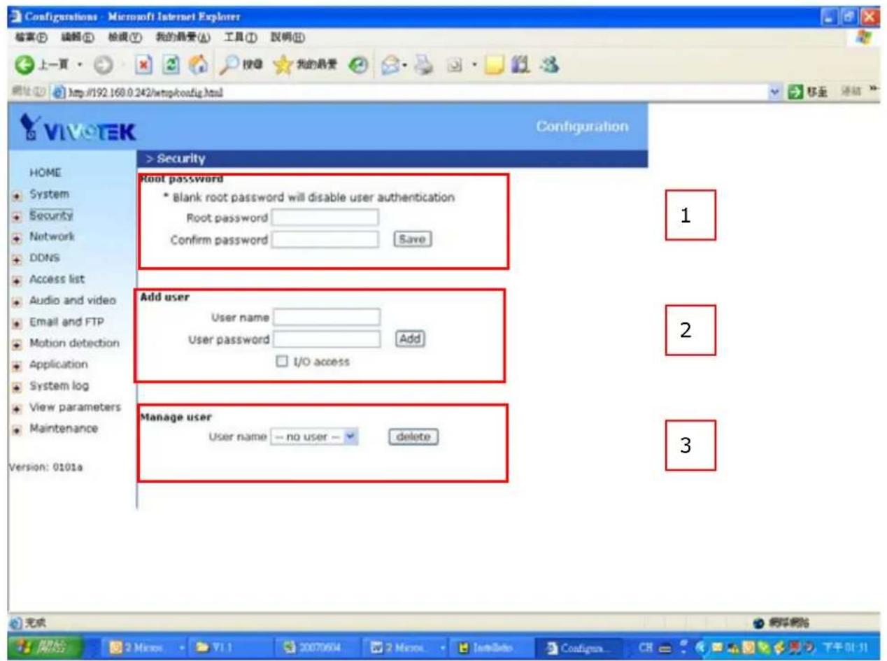
The Network Camera is shipped without any password by default. That means everyone can access the Network Camera including the configuration as long as the IP address is known. It is necessary to assign a password if the Network Camera is intended to be accessed by others. Type a new word twice in ⏻ to enable protection. This password is used to identify the administrator. Then add an account with user name and password for your friends in 2 Ⓑ Network Camera can provide twenty accounts for your valuable customers or friends. You may delete some users from ⑤
Build a security application
The Administrator can use the built-in motion detection to monitor any movement to perform many useful security applications. To upload the snapshots, users can choose either email or FTP according to user's needs. Both e-mail and FTP use the network settings on the Email and FTP page. Refer to the definition section for detail configuration.
- Click on "Configuration" on homepage,
- Click on "Motion detection" at the left column,
- Check "Enable motion detection",
- Click on new to have a new window to monitor video,
- Type in a name to identify the new window,
- Use the mouse to click, hold, and drag the window corner to resize or the title bar to move,
- Fine-tune using the "Sensitivity" and "Percentage" fields to best suit the camera's environment. Higher "Sensitivity" detects the slighter motion. Higher "Percentage" discriminates smaller objects,
- Clicking on "Save" enables the activity display. Green means the motion in the window is under the watermark set by Administrator and red means it is over the watermark,
- Click on "Application" at the left column,
- Check the weekdays as you need and give the time interval to monitor the motion detection every day,
- Select the Trigger on Motion detection.
- Set the delay before detecting next motion to avoid continuous false alarms following the original event,
- Set the number of pre-event and post-event images to be uploaded,
- Check the window name set in step 5,
- Check the way to upload snapshot,
Click on save to validate.
Software revision upgrade
Customers can obtain the up-to-date software from the web site of Vivotek. An easy-to-use Upgrade Wizard is provided to upgrade the Network Camera with just a few clicks. The upgrade function is opened to the Administrator only. To upgrade the system, follow the procedures below.
- Download the firmware file named "xxx.pkg" from the appropriate product folder.
- Run the Upgrade Wizard and proceed following the prompts. Refer to the instructions of the Upgrade Wizard for details.
- Or upgrade firmware from HTTP web page directly
- The whole process will finish in a few minutes and it will automatically restart the system.

If power fails during the writing process of Flash memory, the program in the memory of the Network Camera may be destroyed permanently. If the Network Camera cannot restart properly, ask your dealer for technical service.
Definitions in Configuration
Only the Administrator can access system configuration. Each category in the left column will be explained in the following pages. The bold texts are the specific phrases on the Option pages. The Administrator may type the URL below the figure to directly enter the frame page of configuration. If the Administrator also wants to set certain options through the URL, read the reference appendix for details.
text_image
VIVO TEK Configuration HOME System Security Network DDNS Access list Audio and video Email and FTP Motion detection Application System log View parameters Maintenance Version: 0100c > System Host name : Network Camera Turn off the LED indicator Daylight Saving Time Time zone: GMT+08:00 Beijing, Chongging, Hong Kong, Kuala Lumpur, Singapore, Taipei Keep current date and time Sync with computer time PC date: 2006/12/26 [yyyy/mm/dd] PC time: 16:26:42 [hh:mm:ss] Manual Date: 2006/12/25 [yyyy/mm/dd] Time: 21:22:00 [hh:mm:ss] Automatic NTP server: skip to invoke default server Update One hour interval: DI and DO Digital input: normal status is Low Digital output: normal status is Grounded Reset digital output after 1 seconds Save
System parameters
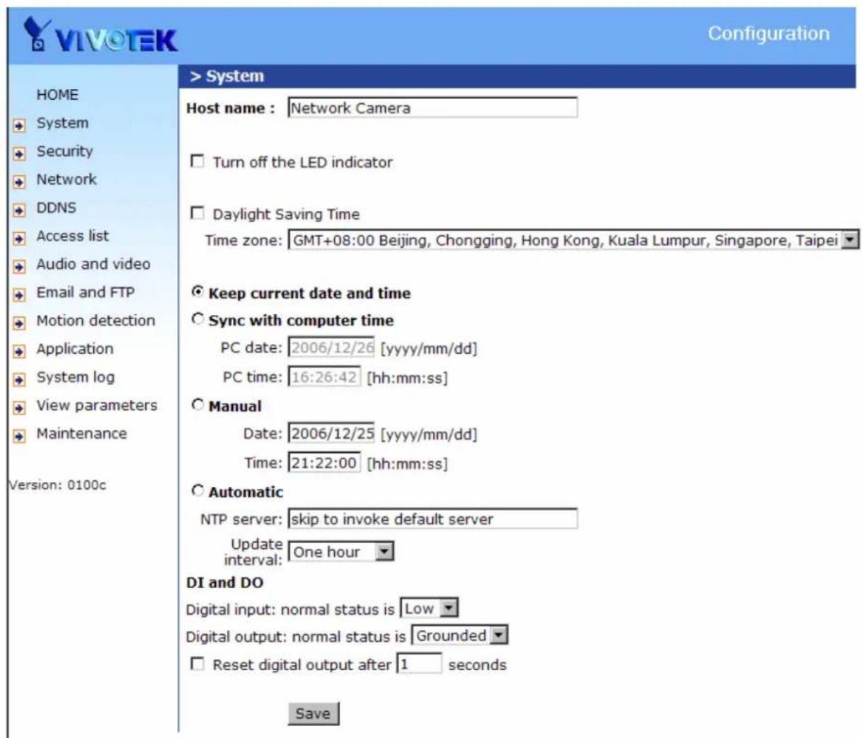
"Host name" The text displays the title at the top of the main page.
"Turn off the LED indicator" Check this option to shut off the LED on the rear. It can prevent the camera's operation being noticed.
"Keep current date and time" Click on this to reserve the current date and time of the Network Camera. An internal real-time clock maintains the date and time even when the power of the system is turned off.
"Sync with computer time" Synchronizes the date and time of the Network Camera with the local computer. The read-only date and time of the PC is displayed as updated.
"Manual" Adjust the date and time according to what is entered by the Administrator. Notice the format in the related fields while doing the entry.
"Automatic" Synchronize with the NTP server over the Internet whenever the Network Camera starts up. It will fail if the assigned time-server cannot be reached.
"NTP server" Assign the IP address or domain name of the time-server. Leaving the text box blank connects the Network Camera to the default time-servers.
"Time zone" Adjust the time with that of the time-servers for local settings.
"Update interval" Select hourly, daily, weekly, or monthly update with the time on the NTP server.
"Digital input" Select High or Low to define normal status of the digital input.
"Digital output" Select Grounded or Open to define normal status of the digital output.
"Reset digital output" The check box enable the function of resetting digital output.
When the digital output is triggered, after the number time the digital output will reset into normal state.
Remember to click on Save to immediately validate the changes. Otherwise, the correct time will not be synchronized.
Security settings
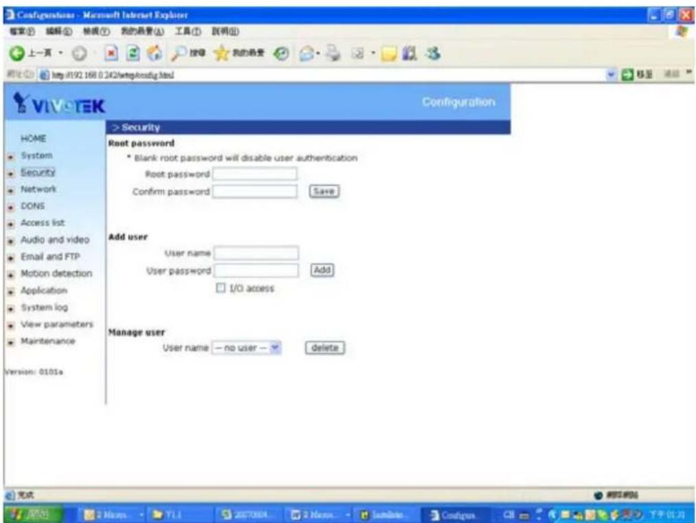
"Root password" Change the Administrator's password by typing in the new password identically in both text boxes. The typed entries will be displayed as asterisks for security purposes. After pressing Save, the web browser will ask the Administrator for the new password for access.
"Add user" Type the new user's name and password and press Add to insert the new entry. The new user will be displayed in the user name list. There is a maximum of twenty user accounts. Checking I/O access can enable user to use D/I and D/O applications
"Manager user" Pull down the user list to find the user's name and press Delete to complete.
text_image
Configurations - Microsoft Internet Explorer 搜索(E) 编辑(E) 检索(T) 我的场景(A) 工具(I) 説明(G) 上一頁 http://92.168.0.242/wltpkconfig.html VIV-TEK Configuration HOME System Security Network DONS Access list Audio and video Email and FTP Motion detection Application System log View parameters Maintenance Version: 0101a > Security Root password • Blank root password will disable user authentication Root password Confirm password Save Add user User name User password Add I/O access Manage user User name — no user — delete 完成 © Website © Home YLL 2007004 2 News • Initiate Configus CII 下于计划Network settings
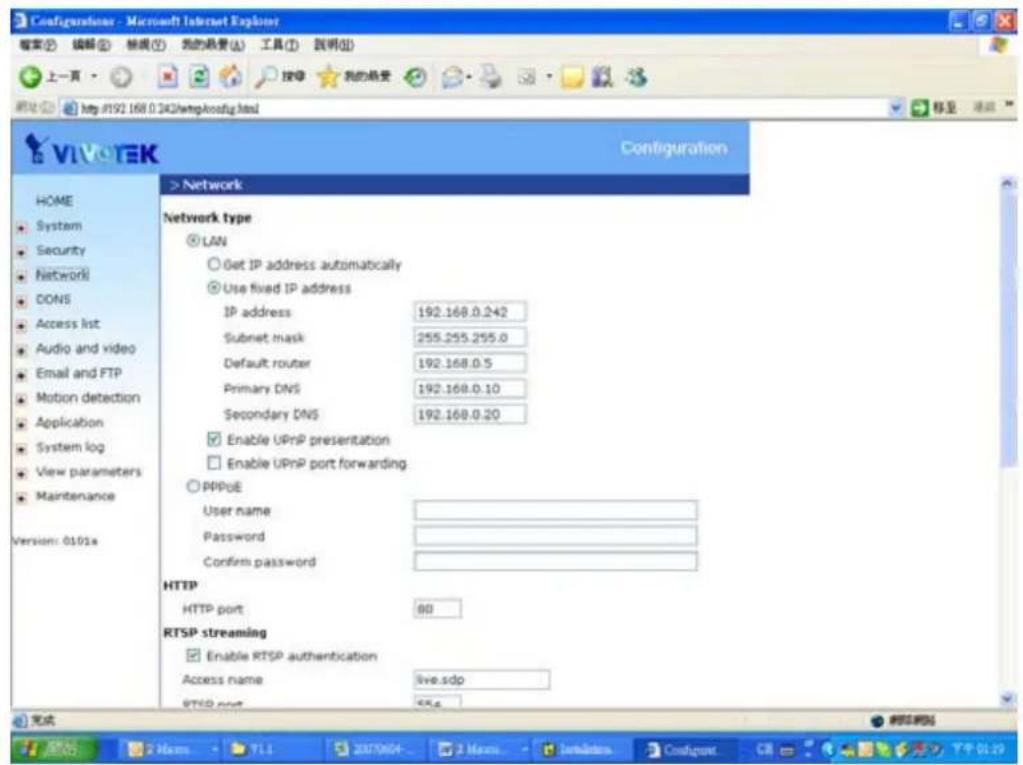
Any changes made on this page will restart the system in order to validate the changes.
Make sure every field is entered correctly before clicking on Save
Network type
"LAN" & "PPPoE"
The default type is LAN. Select PPPoE if using ADSL
"Get IP address automatically" & "Use fixed IP address"
The default status is "Get IP address automatically". This can be tedious having to perform software installation whenever the Network Camera starts. Therefore, once the network settings, especially the IP address, have been entered correctly, select
"Use fixed IP address" then the Network Camera will skip installation at the next boot. The Network Camera can automatically restart and operate normally after a power outage. Users can run IP installer to check the IP address assigned to the Network Camera if the IP address is forgotten or using the UPnP function provided by the Network Camera (MS Windows XP provides UPnP function at My Network Place).
"IP address" This is necessary for network identification.
"Subnet mask" This is used to determine if the destination is in the same subnet. The default value is "255.255.255.0".
"Default router" This is the gateway used to forward frames to destinations in a different subnet. Invalid router setting will fail the transmission to destinations in different subnet.
"Primary DNS" The primary domain name server that translates hostnames into IP addresses.
"Secondary DNS" Secondary domain name server that backups the Primary DNS.
"Enable UPnP presentation" Enable the UPnP camera short cut
"Enable UPnP port forwarding" Enable uPnP port forwarding
"PPPoE" If using the PPPoE interface, fill the following settings from ISP
"User name" The login name of PPPoE account
"Password" The password of PPPoE account
"Confirm password" Input password again for confirmation
HTTP
"Http port" This can be other than the default Port 80. Once the port is changed, the users must be notified the change for the connection to be successful. For instance, when the Administrator changes the HTTP port of the Network Camera whose IP address is 192.168.0.100 from 80 to 8080, the users must type in the web browser "http://192.168.0.100:8080" instead of "http://192.168.0.100".
RTSP Streaming
"Access name" This is the access URL for making connection from client software. Using rtsp://
"RTSP port" This can be other than the default Port 554
text_image
Configuration - Microsoft Internet Explorer 搜索(E) 编辑(E) 框架(T) 我的场景(A) 工具(T) 説明(O) 上一页 按导 我的场景 网址 http://9192.168.0.242/#wtpkhostg.html VIVoTEK Configuration > Network Network type ○ LAN ○ Get IP address automatically ○ Use fixed IP address IP address 192.168.0.242 Subnet mask 255.255.255.0 Default router 192.168.0.5 Primary DNS 192.168.0.10 Secondary DNS 192.168.0.20 ■ Enable UPnP presentation □ Enable UPnP port forwarding ○ PPPoE User name Password Confirm password HTTP HTTP port 80 RTSP streaming ■ Enable RTSP authentication Access name live.sdp RTSP port 99.6 完成 刷新网站 Home System Security Network DONS Access list Audio and video Email and FTP Motion detection Application System log View parameters Maintenance Version: 0101a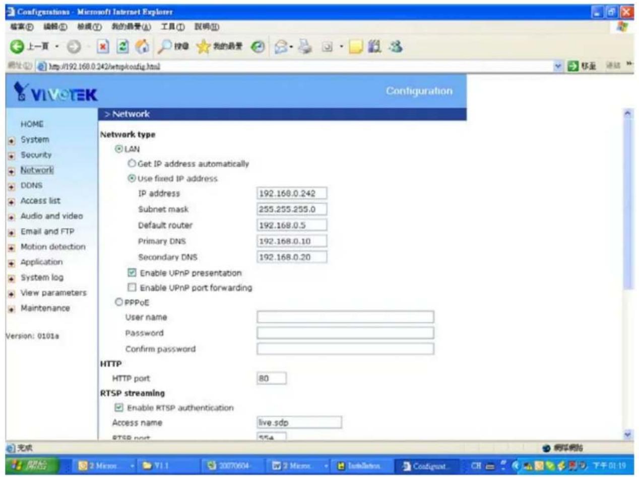
text_image
Configurations - Microsoft Internet Explorer 檔案(E) 編輯(E) 檢報(Y) 我的最愛(A) 工具(T) 說明(R) 上一頁 http://192.168.0.242/netpkodig.html VIVETEK Configuration HOME System Security Network DDNS Access list Audio and video Email and FTP Motion detection Application System log View parameters Maintenance Version: 0101a > Network Network type LAN Get IP address automatically Use fixed IP address IP address 192.168.0.242 Subnet mask 255.255.255.0 Default router 192.168.0.5 Primary DNS 192.168.0.10 Secondary DNS 192.168.0.20 Enable UPnP presentation Enable UPnP port forwarding PPPoE User name Password Confirm password HTTP HTTP port 80 RTSP streaming Enable RTSP authentication Access name live.sdp RTSP port 954 完成 开始 2 Minor YI 1 2 Micro DataSetn Configunt CH 下午 01:19DDNS
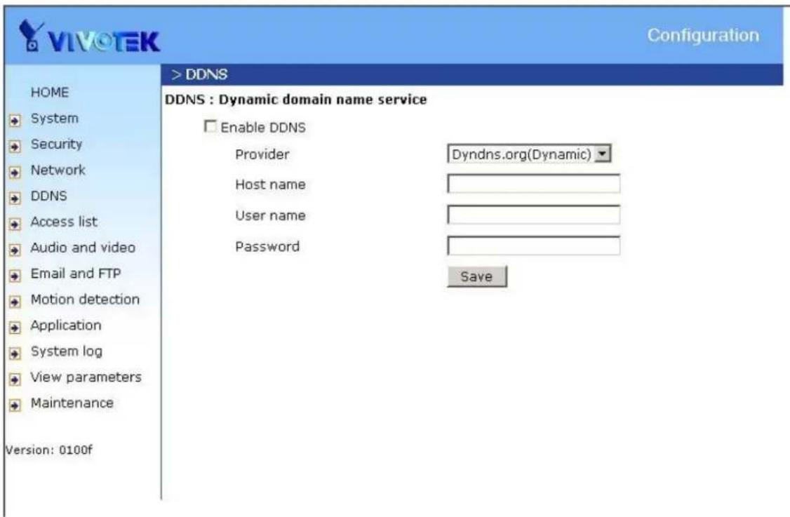
"Enable DDNS" This option turns on the DDNS function.
"Provider" The provider list contains four hosts that provide DDNS services. Please connect to the service provider's website to make sure the service charges.
"Host Name" If the User wants to use DDNS service, this field must be filled. Please input the hostname that is registered in the DDNS server.
"Username/E-mail" The Username or E-mail field is necessary for logging in the DDNS server or notify the User of the new IP address. Note: when this field is input as "Username" the following field must be input as "Password".
"Password/Key" Please input the password or key to get the DDNS service.
"Save" Click on this button to save current settings for the DDNS service and UPnP function.
text_image
VIVOTEK Configuration > DDNS DDNS : Dynamic domain name service Enable DDNS Provider Dyndns.org(Dynamic) Host name User name Password Save HOME System Security Network DDNS Access list Audio and video Email and FTP Motion detection Application System log View parameters Maintenance Version: 0100fAccess List
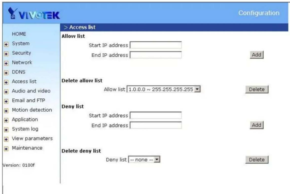
The access list is to control the access permission of clients by checking the client IP address.
There are two lists for permission control: Allow List and Deny List. Only those clients whose IP address is in the Allow List and not in the Deny List can connect to the Video Server or Network Camera for receiving the audio/video streaming.
Both Allow List and Deny List consist of a list of IP ranges. If you want to add a new IP address range, type the Start IP Address and End IP Address in the text boxes and click on the Add button. If you want to remove an existing IP address range, just select from the pull-down menu and click on the Delete button.
Both the Allow List and Deny List can have 20 entries.
text_image
VIVOTEK Configuration HOME System Security Network DDNS Access list Audio and video Email and FTP Motion detection Application System log View parameters Maintenance Version: 0100f > Access list Allow list Start IP address End IP address Add Delete allow list Allow list 1.0.0.0 ~ 255.255.255.255 Delete Deny list Start IP address End IP address Add Delete deny list Deny list -- none -- DeleteAudio and Video
General
"Configure for computer viewing" To make quick setting for computer viewing "Configure for mobile viewing" To make quick setting for cell phone viewing
Video Settings
"Video title" The text string can be displayed on video
"Color" Select either for color or monochrome video display.
"Frame Size" There are four options for video sizes. "160x120". "176x144", "320x240", "640x480".
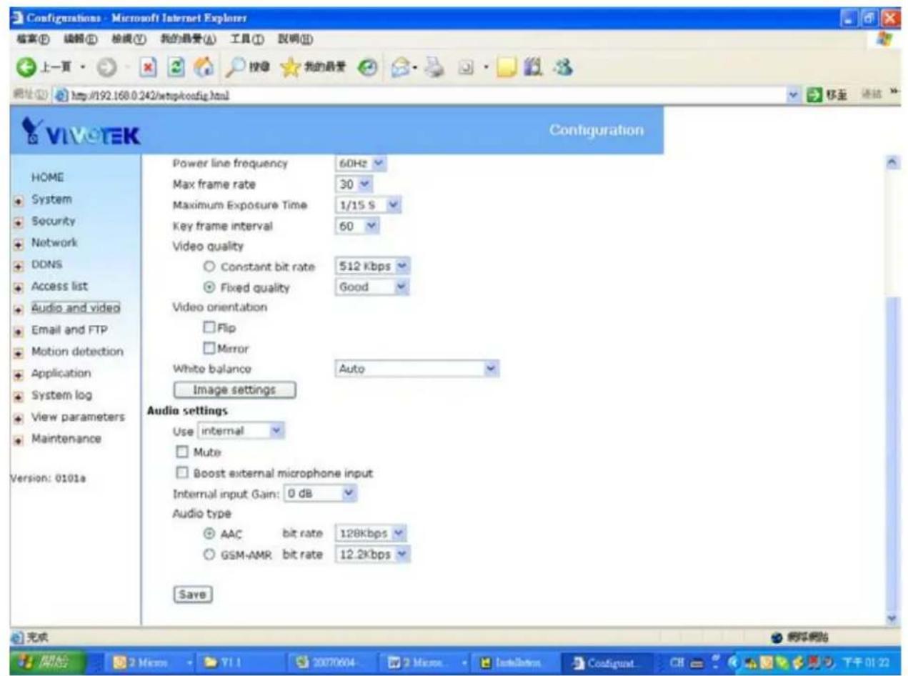
"Power line frequency (for fluorescent light)", the fluorescent light will flash according to the power line frequency that depends on local utility. Change the frequency setting to eliminate uncomfortable flash image when the light source is only fluorescent light.
There are three dependent parameters provided for video performance adjustment.
"key frame interval"
"Max frame rate" This limits the maximal refresh frame rate, which can be combined with the "Video quality" to optimize bandwidth utilization and video quality. Choose "Constant bit rate" If the user wants to fix the bandwidth utilization regardless of the video quality, choose "Fixed quality" and select the desired bandwidth. The video quality may be poor due to the sending of maximal frame rate within the limited bandwidth when images are moving rapidly. Consequently, to ensure detailed video quality (quantization rate) regardless of the network, it will utilize more bandwidth to send the maximal frames when images change drastically.
Video orientation
"Flip" Vertically rotate the video.
"Mirror" Horizontally rotate the video. Check options both if the Network Camera is installed upside down.
"White balance" Adjust the value for best color temperature.
Audio settings
"Use" Switch "internal" or "microphone" to set up the source of audio input "mute" Audio mute
"Boost external microphone input" Enhance the gain of the external microphone "Internal input Gain" Modify the gain of the internal audio input
"Audio type" Select audio codec "AAC" or "GSM-AMR" and the bit rate
text_image
Configurations - Microsoft Internet Explorer 档案(E) 编辑(E) 检载(T) 我的最爱(A) 工具(T) 说明(U) 上一页 按印 我的最爱 网址 http://192.168.0.242/wmpkconfig.html 移至 连续 VIVO-TEK Configuration HOME System Security Network DDNS Access list Audio and video Email and FTP Motion detection Application System log View parameters Maintenance Version: 0101a Power line frequency 60Hz Max frame rate 30 Maximum Exposure Time 1/15 S Key frame interval 60 Video quality Constant bit rate 512 Kbps Fixed quality Good Video orientation Flip Mirror White balance Auto Image settings Audio settings Use internal Mute Boost external microphone input Internal input Gain: 0 dB Audio type AAC bit rate 128Kbps GSM-AMR bit rate 12.2Kbps SaveImage Settings
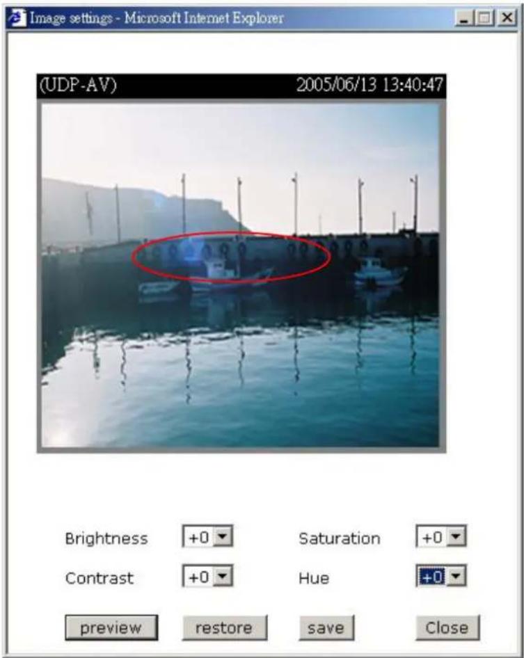
Image settings Click on this button to pop up another window to tune "Brightness", "Contrast", "Hue" and "Saturation" for video compensation. Each field has eleven
text_image
(UDP-AV) 2005/06/13 13:40:47 Brightness +0 Saturation +0 Contrast +0 Hue +0 preview restore save Closelevels ranged from -5 to +5. In "Brightness" and "Contrast" fields the value 0 indicates auto tuning. The user may press Preview to fine-tune the image. When the image is O.K., press Save to set the image settings. Restore Click on this to recall the original settings without incorporating the changes.
Email & FTP
When the SMTP server support SMTP authentication, users need to give the valid user name and password to send email via the server.
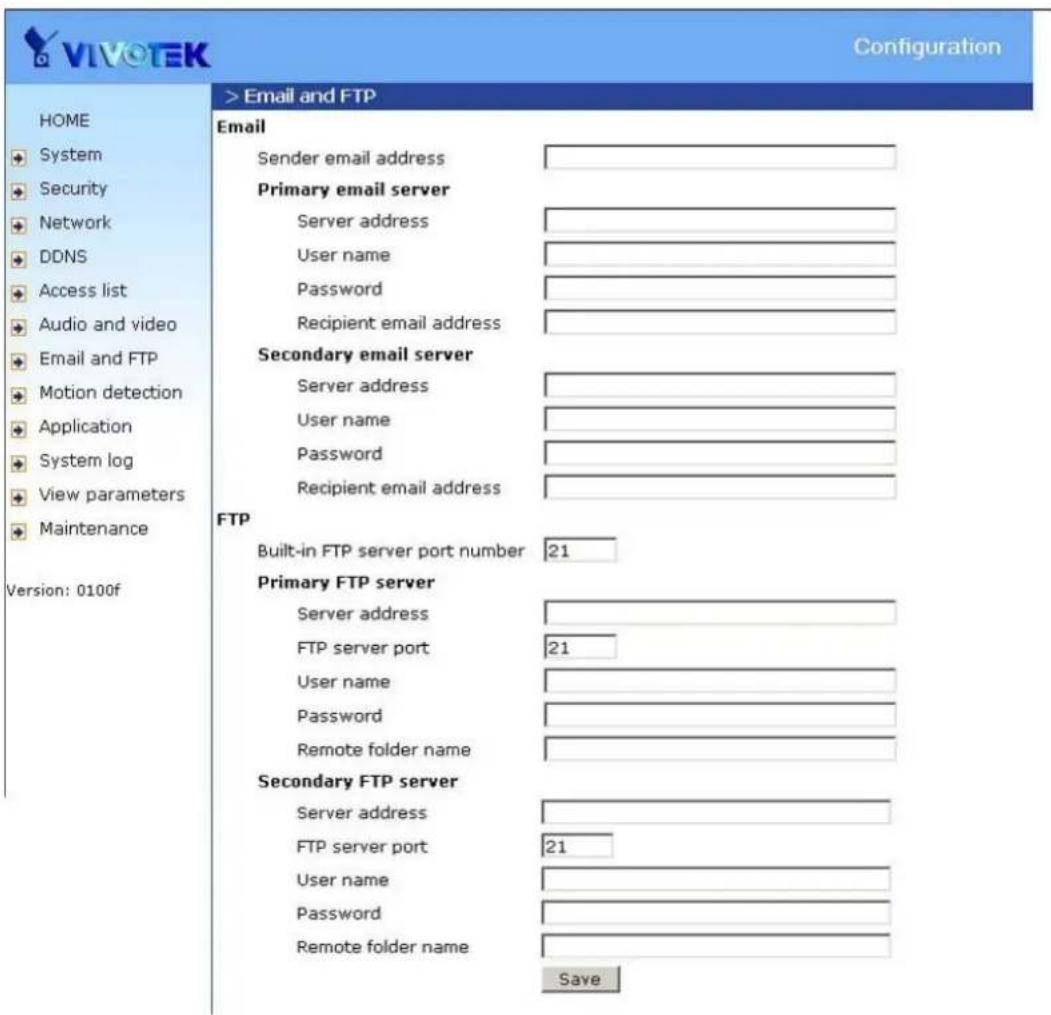
"Sender email address", the email address of the sender.
There are two external mail server can be configured, primary and secondary email server, The network camera will use primary server as default, and use secondary server when primary server is unreachable.
"Server address" The domain name or IP address of the external email server.
"User name" This granted user name on the external email server.
"Password" This granted password on the external email server.
"Recipient email address" The email address of the recipients for snapshots or log file. Multiple recipients must be separated by semicolon, ';'
FTP
"Built-in FTP server port number" This can be other than the default port 21. The user can change this value from 1025 to 65535. After the changed, the external FTP client program must change the server port of connection accordingly.
There are two external FTP server can be configured, primary and secondary FTP server, The network camera will use primary server as default, and use secondary server when primary server is unreachable.
"Server address" The domain name or the IP address of the external FTP server. The following user settings must be correctly configured for remote access.
"FTP server port" This can be other than the default port 21. The user can change this value from 1025 to 65535.
"User name" Granted user name on the external FTP server.
"Password" Granted password on the external FTP server.
"Remote folder name" Granted folder on the external FTP server. The string must conform to that of the external FTP server. Some FTP servers cannot accept preceding slash symbol before the path without virtual path mapping. Refer to the instructions for the external FTP server for details. The folder privilege must be open for upload.
text_image
VIVOTEK Configuration HOME System Security Network DDNS Access list Audio and video Email and FTP Motion detection Application System log View parameters Maintenance Version: 0100f > Email and FTP Email Sender email address Primary email server Server address User name Password Recipient email address Secondary email server Server address User name Password Recipient email address FTP Built-in FTP server port number 21 Primary FTP server Server address FTP server port 21 User name Password Remote folder name Secondary FTP server Server address FTP server port 21 User name Password Remote folder name SaveMotion detection
"Enable motion detection" Check this option to turn on motion detection.
New Click on this button to add a new window. At most three windows can exist simultaneously. Use the mouse to click, hold, and drag the window frame to resize or the title bar to move. Clicking on the 'x' at the upper right-hand corner of the window to delete the window. Remember to save in order to validate the changes.
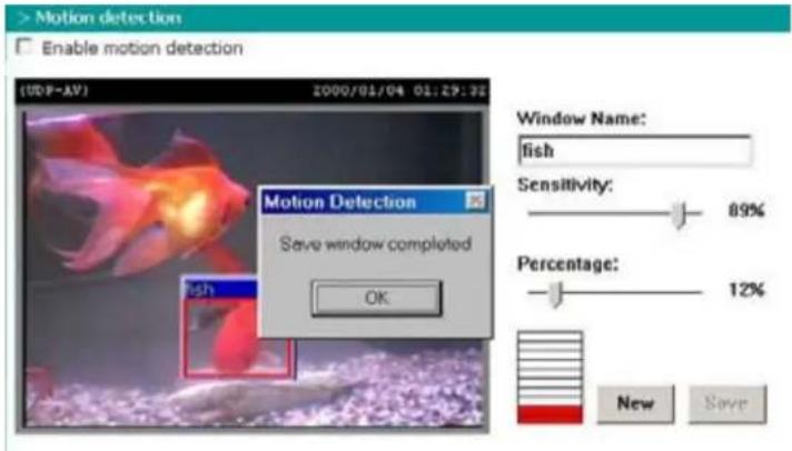
Save Click on this button to save the related window settings. A graphic bar will rise or fall depending on the image variation. A green bar means the image variation is under monitoring level and a red bar means the image variation is over monitoring level. When the bar goes red, the detected window will also be outlined in red. Going back to the homepage, the monitored window is hidden but the red frame shows when motion is detected.
"Window Name" The text will show at the top of the window.
"Sensitivity" This sets the endurable difference between two sequential images.
"Percentage" This sets the space ratio of moving objects in the monitoring window. Higher sensitivity and small percentage will allow easier motion detection.
The following figure shows the screen when Save is clicked. The monitoring window has been outlined in red and the graphic bar goes red since the goldfish is moving.
text_image
> Motion detection Enable motion detection (UDP-AV) 2000/01/04 01:29:22 Motion Detection Save window completed OK Window Name: fish Sensitivity: 89% Percentage: 12% New SaveApplication settings
Application
Application has two snapshot, one video clip and one digital output.
"Status" ON/OFF show the status of application.
"Sun" \~ "Sat" Select the days of the week to perform the application.
"Time" show "Always" or input the time interval.
"Trigger" Event trigger type has digital input, motion detection and sequential.
"Send" After Event has been triggered, IP cam will send something by email, ftp or trigger digital output.
| VIVOTEK Configuration | ||||||||||||
| HOME System Security Network DDNS Access list Audio and video Email and FTP Motion detection Application System log View parameters Maintenance Version: 0100b | > Application | |||||||||||
| Status | Sun | Mon | Tue | Wed | Thu | Fri | Sat | Time | Trigger | Send | ||
| Snapshot #1 | OFF | always | motion | |||||||||
| Snapshot #2 | OFF | always | motion | |||||||||
| Video Clip | OFF | V | V | V | V | always | motion | |||||
| Digital Output | ON | V | V | V | V | V | V | V | always digitalinput do | |||
Snapshot
"Enable snapshot" Enable/Disable snapshot application.
Weekly schedule
"Sun" \~ "Sat" Select the days of the week to perform the application. Select "Always" or input the time interval.
Snapshot file name prefix
The prefix name will be added on the file name of the snapshot images.
Digital input
Network Camera will send snapshots when the digital input is triggered.
Send out the snapshot while motion detection
There are three windows for motion detection each can be assigned a name. Select the windows which need to be monitored. If motion detection has not been set up, "undefined" will be shown instead of the window title. If this happens, clicking on "Motion detection" and a note will show to direct the User to the configuration page for motion detection.
"Send pre-event image(s)" The number of pre-snapshots will be captured and send when a condition is triggered.
"Send post-event image(s)" The number of post-snapshots will be captured and send when a condition is triggered.
"Delay second(s) before detecting next motion" Set the time delay before restarting to check on the triggering condition when the current condition is triggered.
Sequential operation
"Snapshot interval : second(s)" Network Camera will send snapshots at the specified intervals to the external server using the method selected below. Remember: This operation is still subject to the conditions set in the weekly schedule.
Method for sending snapshot
"Email" This selects the uploading method following the intervals set above. The snapshot named "prefix-yyyyymmdd-hhmmss.jpg" will be attached in the email.
"FTP" The snapshots will be uploaded to the external FTP server with the file name defined in the next option. This can also be used to refresh the captured images stored in the external web server to build creative homepages.
"FTP put snapshots with date and time suffix" This option sets up the snapshot capture date and time, which can be used to easily differentiate the snapshot file names in the sequential operation. For instance, "prefix-20030102-030405.jpg" means the JPEG image was captured in the year 2003, January the 2^nd , at 3 o'clock, 4 minute, and 5 second. If this suffix is omitted, the file named "video.jpg" on the external FTP server will be refreshed at the specified interval.

VIVO TEK
Configuration
HOME

System

Security

Network

DDNS

Access list

Audio and video

Email and FTP

Motion detection

Application

System log

View parameters

Maintenance
Version: 0100b
> Snapshot
Snapshot
Enable snapshot #1
Weekly schedule
□ Sun □ Mon □ Tue □ Wed □ Thu □ Fri □ Sat
Time
Always
From 00:00 to 00:00 [hh:mm]
Snapshot file name prefix
Trigger
Digital input
Motion detection
Detect motion in :
Note: Please configure Motion detection first.
Send 1 pre-event image(s) Send 1 post-event image(s) Delay 2 second(s) before detecting the next event
Sequential
Snapshot interval : 5 second(s)
Send snapshot by
C FTP
☐ FTP put snapshots with date and time suffix
Save
Video clip
"Enable video clip" Enable/Disable video clip application.
Weekly schedule
"Sun" \~ "Sat" Select the days of the week to perform the application. Select "Always" or input the time interval.
Video clip file name prefix
The prefix name will be added on the file name of the video clip files.
Video clip max file size
Define the maximal file size of one video clip file.
Digital input
Network Camera will send video clip file when the digital input is triggered.
Send out the video clip while motion detection
There are three windows for motion detection each can be assigned a name. Select the windows which need to be monitored. If motion detection has not been set up, "undefined" will be shown instead of the window title. If this happens, clicking on "Motion detection" and a note will show to direct the User to the configuration page for motion detection.
"Delay second(s) before detecting next event" Set the time delay before restarting to check on the triggering condition when the current condition is triggered.
In the event that the available network bandwidth is limited, video clips sent to FTP or e-mail may be corrupted and can not be opened.
Sequential operation
"Snapshot interval : second(s)" Network Camera will send video clip file at the specified intervals to the external server using the method selected below. Remember: This operation is still subject to the conditions set in the weekly schedule.
Method for sending snapshot
"Email" This selects the uploading method following the intervals set above. The snapshot named "prefix-yyyyymmdd-hhmmss.jpg" will be attached in the email.
"FTP" The snapshots will be uploaded to the external FTP server with the file name defined in the next option. This can also be used to refresh the captured images stored in the external web server to build creative homepages.
"FTP put snapshots with date and time suffix" This option sets up the snapshot capture date and time, which can be used to easily differentiate the snapshot file names in the sequential operation. For instance, "prefix-20030102-030405.jpg" means the JPEG image was captured in the year 2003, January the 2^nd , at 3 o'clock, 4 minute, and 5 second. If this suffix is omitted, the file named "video.jpg" on the external FTP server will be refreshed at the specified interval.

VIVO TEK
Configuration
HOME
System
→ Security
Network
DDNS
Access list
Audio and video
Email and FTP
Motion detection
Application
System log
View parameters
Maintenance
Version: 0100b
> Videoclip
Video Clip
Enable videoclip
Weekly schedule
□ Sun □ Mon ▼ Tue ▼ Wed ▼ Thu □ Fri ▼ Sat
Time
Always
○ From 00:00 to 00:00 [hh:mm]
Video clip file name prefix
Video clip max file size 500 KB
Trigger
Digital input
Motion detection
Detect motion in :
Note: Please configure Motion detection first.
Delay 10 second(s) before detecting the next event
Sequential
Video clip interval: 10 second(s)
Send videoclip by
C FTP
☐ FTP put Video clips with date and time suffix
Save
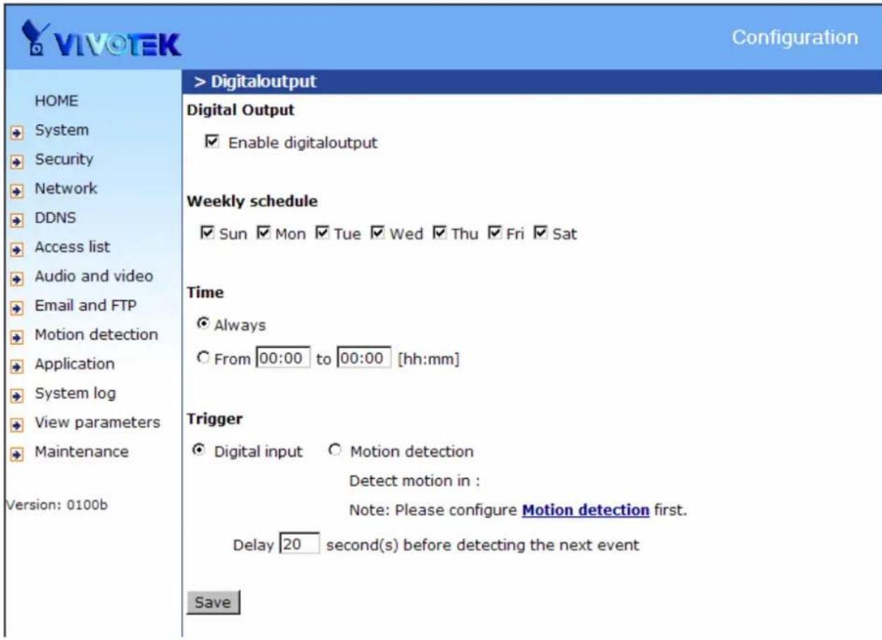
Digital output
"Enable digital output" Enable/Disable digital output application.
Weekly schedule
"Sun" \~ "Sat" Select the days of the week to perform the application. Select "Always" or input the time interval.
Digital input
Network Camera will trigger digital output when the digital input is triggered.
Trigger digital output while motion detection
There are three windows for motion detection each can be assigned a name. Select the windows which need to be monitored. If motion detection has not been set up, "undefined" will be shown instead of the window title. If this happens, clicking on "Motion detection" and a note will show to direct the User to the configuration page for motion detection.
"Delay second(s) before detecting next event" Set the time delay before restarting to check on the triggering condition when the current condition is triggered.
text_image
VIVOTEK Configuration HOME System Security Network DDNS Access list Audio and video Email and FTP Motion detection Application System log View parameters Maintenance Version: 0100b > Digitaloutput Digital Output Enable digitaloutput Weekly schedule Sun Mon Tue Wed Thu Fri Sat Time Always From 00:00 to 00:00 [hh:mm] Trigger Digital input Motion detection Detect motion in : Note: Please configure Motion detection first. Delay 20 second(s) before detecting the next event SaveSystem log
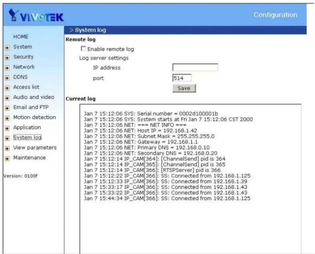
The Network camera support log the system messages on remote server. The protocol is compliant to RFC 3164. If you have external Linux server with syslogd service, use "-r" option to turn on the facility for receiving log from remote machine. Or you can use some software on Windows which is compliant to RFC 3164.
Check "Enable remote log" and input the "IP address" and "port" number of the log server to enable the remote log facility.
In the "Current log", it displays the current system log file. The content of the log provides useful information about configuration and connection after system boot-up.
text_image
VIVOTEK Configuration > System log Remote log Enable remote log Log server settings IP address port 514 Save Current log Version: 0100f Jan 7 15:12:06 SYS: Serial number = 0002d100001b Jan 7 15:12:06 SYS: System starts at Fri Jan 7 15:12:06 CST 2000 Jan 7 15:12:06 NET: === NET INFO === Jan 7 15:12:06 NET: Host IP = 192.168.1.42 Jan 7 15:12:06 NET: Subnet Mask = 255.255.255.0 Jan 7 15:12:06 NET: Gateway = 192.168.1.1 Jan 7 15:12:06 NET: Primary DNS = 192.168.0.10 Jan 7 15:12:06 NET: Secondary DNS = 192.168.0.20 Jan 7 15:12:14 IP_CAM[364]: [ChannelSend] pid is 364 Jan 7 15:12:14 IP_CAM[365]: [ChannelSend] pid is 365 Jan 7 15:12:14 IP_CAM[366]: [RTSPServer] pid is 366 Jan 7 15:12:22 IP_CAM[366]: SS: Connected from 192.168.1.125 Jan 7 15:12:33 IP_CAM[366]: SS: Connected from 192.168.1.39 Jan 7 15:33:17 IP_CAM[366]: SS: Connected from 192.168.1.43 Jan 7 15:33:22 IP_CAM[366]: SS: Connected from 192.168.1.43 Jan 7 15:44:34 IP_CAM[366]: SS: Connected from 192.168.1.125Viewing system parameters
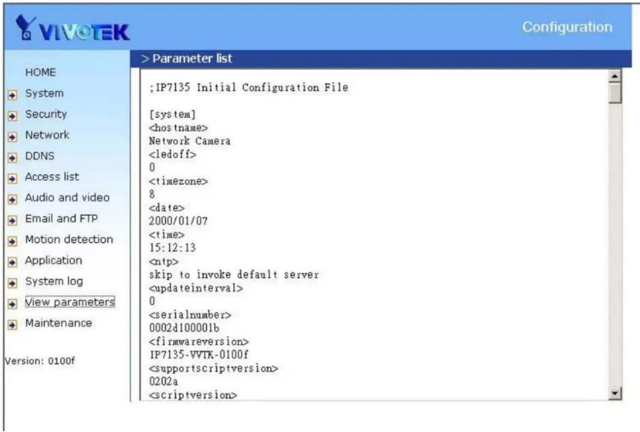
Click on this link on the configuration page to view the entire system's parameter set. The content is the same as those in CONFIG.INI.
text_image
;IP7135 Initial Configuration File [system]Maintenance
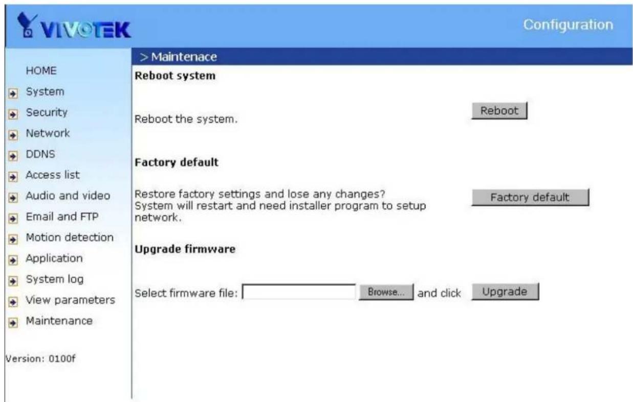
Three actions can be selected
"reboot" click the reboot button to restart system
"factory default" Click on Factory default button on the configuration page to restore the factory default settings. Any changes made so far will be lost and the system will be reset to the initial factory settings. The system will restart and require the installer program to set up the network again.
"upgrade firmware" Select the firmware file and click upgrade button
text_image
VIVOTEK Configuration HOME System Security Network DDNS Access list Audio and video Email and FTP Motion detection Application System log View parameters Maintenance Version: 0100f > Maintenance Reboot system Reboot the system. Reboot Factory default Restore factory settings and lose any changes? System will restart and need installer program to setup network. Factory default Upgrade firmware Select firmware file: Browse... and click UpgradeAppendix
A. Troubleshooting
Status LED
The following table lists the LED patterns in general.
| Status LED Color | Description |
| Blinking red | Power is being supplied to the camera. |
| Solid green | The camera is booting up. |
| Solid green with blinking red in between | The camera is trying to obtain an IP address. |
| Solid green and red | An IP address is successfully assigned to the camera. |
| Solid red with blinking green in between | The camera is working. |
| Blinking red and green | During firmware upgrading |
Reset and restore
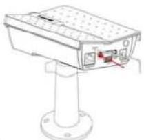
There is a button in the back of the Network Camera. It is used to reset the system or restore the factory default settings. Sometimes resetting the system sets the system back to normal state. If the system problems remain after reset, restore the factory settings and install again.
natural_image
Technical line drawing of a security camera mounted on a stand (no text or symbols visible)RESET: Click on the button.
RESTORE:
- Press on the button continuously.
- Wait for self-diagnostic to run twice.
- Free the button as soon as the second self-diagnostic starts.

Restoring the factory defaults will erase any previous settings. Reset or restore the system after power on.
B. URL commands of the Network Camera
For some customers who already have their own web site or web control application, the Network Camera can be easily integrated through convenient URLs. This section lists the commands in URL format corresponding to the basic functions of the erase Network Camera.
Get server parameter values
Note: This request require administrator access
Method: GET/POST
Syntax:
http://<servername>/cgi-bin/admin/getparam.cgi?[<parameter>][&<parameter>...]
where the
When query parameter values, the current parameter value are returned.
Successful control requests returns paramter pairs as follows.
Return:
HTTP/1.0 200 OK\r\n
Content-Type: text/html\r\n
Context-Length:
\r\n
where
[
Example: request IP address and it's response
Request:
http://192.168.0.123/cgi-bin/admin/getparam.cgi?network_ipaddress
Response:
HTTP/1.0 200 OK\r\n
Content-Type: text/html\r\n
Context-Length: 33\r\n
\r\n
network.ipaddress=192.168.0.123\r\n
Set server parameter values
Note: This request require administrator access
Method: GET/POST
Syntax:
http://
[nosync=<value>&]<parameter>=<value>
[&<parameter>=<value>...][&return=<return page>]
| parameter value | description | |
| _<group>_ | value to assigned | Assignto the parameter_<group>_.. |
| return | Redirect to the pageafter the parameter is assigned. Thecan be a full URL path or relative path according the the current path. If you omit this parameter, it will redirect to an empty page.(note: The return page can be a general HTML file(.htm, .html) or a Vivotek server script executable (.vspx) file. It can not be a CGI command. It can not have any extra parameters. This parameter must be put at end of parameter list) |
Return:
HTTP/1.0 200 OK\r\n
Content-Type: text/html\r\n
Context-Length: <length>\r\n
\r\n
<parameter pair>
where <parameter pair> is
<parameter> = <value>\r\n
[<parameter pair>]
Only the parameters that you set and readable will be returned.
Example: Set the IP address of server to 192.168.0.123
Request:
http://myserver/cgi-bin/admin/setparam.cgi?Network_IPAddress=192.168.0.123
Response:
HTTP/1.0 200 OK\r\n
Content-Type: text/html\r\n
Context-Length: 33\r\n
\r\n
network.ipaddress=192.168.0.123\r\n
Available parameters on the server
NOTE: The bold characters in table are the default value of each parameter.
Group: System
| NAME VALUE DESCRIPTION | ||
| hostname(r/w) | host name of server<<Network Camera > | |
| (r/w) | 0 Do not turn off the led indicator ledoff | |
| 1 Turn off the led indicator | ||
| date(r/w) | year, month and date separated by slash. | |
| keep date unchanged | ||
| Using NTP to sync date/time automatically | ||
| time(r/w) | hour, minute and second separated by colon. | |
| keep date unchanged | ||
| Using NTP to sync date/time automatically | ||
| ntp(r/w) | NTP server<skip to invoke default server> | |
| timezone(r/w) | -12 ~ 12 | time zone, 8 means GMT +8:00<8> |
| updateinterval(r/w) | 0 ~ 2592000 | 0 to Disable automatic time adjustment, otherwise, it means the seconds between NTP automatic update interval.<0> |
| serialnumber(r) | racters mac address without hyphen connected | |
| firmwareversion(r) | The version of firmware, including model, company, and version number | |
| restore(w) | 0 Restore the system | parameters to default value. |
| Positive integer | Restore the system parameters to default value and restart the server afterseconds. | |
| reset(w) | 0 ~ 65535 | Restart the server afterseconds. |
| -1 | Not restart the server. | |
| viewmode(r/w) | 0 | Using the profile of viewing by computer |
| 1 Using the profile of viewing by mobile phone | ||
Group: Security
| NAME | VALUE | DESCRIPTION |
| username_<1~20>(r/w) | change user name. | |
| userpass_<0~20>(r/w) | change user's password.The UserPass_0 is root's password. | |
| userattr_<1~20>(r) | [conf] | show user's privilege. The privilege can be- only permit to view live mediaconf - Permit to change server's configuration |
| usercount | 1 ~ 21 | The current account number on the server |
(r) including root.<1>
Group: Network
| NAME VALUE | DESCRIPTION | |
| (r/w) | 0 LANtype | |
| 1 PPPoE | ||
| pppoeuser (r/w) | PPPoE account user name | |
| pppoepass (r/w) | PPPoE account password | |
| resetip (r/w)(restart) | 1 enable to get ipaddress | ss, subnet, router, dns1, dns2 from DHCP server at next reboot |
| 0 Using preset ipaddress | ss, subnet, router, dns1, dns2 | |
| ipaddress (r/w) (restart) | of server <192.168.0.99> | |
| subnet (r/w) (restart) | sk <255.255.255.0> | |
| router (r/w) (restart) | default gateway | |
| dns1 (r/w) (restart) | DNS server | |
| dns2 (r/w) (restart) | DNS server | |
| smtp1 (r/w) | primary SMTP server | |
| mailto1 (r/w) | mail recipient address | |
| mailuser1 (r/w) | User name of primary smtp server | |
| mailpass1 (r/w) | Password of primary smtp server | |
| smtp2(r/w) | secondary SMTP server | |
| mailto2(r/w) | mail recipient address | |
| mailuser2(r/w) | User name of secondary smtp server | |
| mailpass2(r/w) | Password of secondary smtp server | |
| returnemail(r/w) | return email address | |
| localftpport(r/w) | FTP port<21> | |
| ftp1(r/w) | primary FTP server | |
| ftpport1(r/w) | primary FTP port<21> | |
| ftpuser1(r/w) | user name for primary FTP server | |
| ftppass1(r/w) | password for primary FTP server | |
| ftpfolder1(r/w) | upload folder in primary FTP server | |
| (r/w) | 1 Enable passive mode of primary FTP server ftppasvmode1 | |
| 0 Disable passive mode of primary FTP server | ||
| ftp2(r/w) | secondary FTP server | |
| ftpport2(r/w) | secondary FTP port<21> | |
| ftpuser2(r/w) | user name for secondary FTP server | |
| ftppass2(r/w) | password for secondary FTP server | |
| ftpfolder2(r/w) | upload folder in secondary FTP server | |
| (r/w) | 1 Enable passive mode of primary FTP server ftppasvmode2 | |
| 0 Disable passive mode of primary FTP server | ||
| httpport(r/w) (restart) | HTTP port<80> | |
| rtsport(r/w) (restart) | RTSP port<554> | |
| videoport(r) | video Channel port for RTP<5558> | |
| audiport(r) | audio Channel port for RTP<5556> | |
| accessname(r/w) | RTSP access name | |
Group: IPFilter
| NAME VALUE DES | CRIPTION | |
| allowstart_<0~9>(r/w) | 1.0.0.0 ~255.255.255.255 | Allowed starting RTSP connection IP address<1.0.0.0> |
| allowend_<0~9>(r/w) | 1.0.0.0 ~255.255.255.255 | Allowed ending RTSP connection IP address<255.255.255.255> |
| denystart_<0~9>(r/w) | 1.0.0.0 ~255.255.255.255 | Denied starting RTSP connection IP address |
| denyend_<0~9>(r/w) | 1.0.0.0 ~255.255.255.255 | Denied ending RTSP connection IP address |
Group: Video
| NAME VALUE DE | SCRIPTION | |
| text(r/w) | enclosed caption | |
| codectype | 0 | MPEG4 |
| (r/w) 1 MJPEG | ||
| keyinterval (r/w) | 1, 3, 5, 10, 30, 60, 90, 120 | Key frame interval <60> |
| size (r) | 1 half | |
| 2 half x 2 | ||
| 3 normal | ||
| 4 normal x 2 | ||
| 5 double | ||
| 256 This field is obsolete (use resolution) | ||
| resolution (r/w) | 176x144 (for mobile) | Video resolution 176 x 144 |
| 160x120 Video resolution | 160 x 120 | |
| 320x240 Video resolution | 320 x 240 | |
| 640x480 (for computer) | Video resolution 640 x 480 | |
| (r/w) | 0 monochrome color | |
| 1 color | ||
| (r/w) | 0 fix bit rate quality | |
| 1 fix quantization | ||
| quant (r/w) | 1 lowest quality of video | |
| 2 lower quality of video | ||
| 3 normal quality of video | ||
| 4 higher quality of video | ||
| 5 highest quality of video | ||
| bitrate (r/w) | 20000 set bit rate to 20K bps | |
| 30000 set bit rate to 30K bps | ||
| 40000 set bit rate to 40K bps | ||
| 50000 set bit rate to 50K bps | ||
| 64000 set bit rate to 64K bps | ||
| 128000 | set bit rate to 128K bps | |
| 256000 | set bit rate to 256K bps | |
| 512000 | set bit rate to 512K bps | |
| 768000 | set bit rate to 768K bps | |
| 1000000 set bit rate to | 1000K bps | |
| 1500000 set bit rate to | 1500K bps | |
| 2000000 set bit rate to | 2000K bps | |
| 3000000 set bit rate to | 3000K bps | |
| 4000000 set bit rate to | 4000K bps | |
| maxframe (r/w) | 1 set maximum frame rate to 1 fps | |
| 2 set maximum frame rate to 2 fps | ||
| 3 set maximum frame rate to 3 fps | ||
| 5 set maximum frame rate to 5 fps | ||
| 10 set maximum frame rate to 10 fps | ||
| 15 set maximum frame rate to 15 fps | ||
| 20 set maximum frame rate to 20 fps | ||
| 25 set maximum frame rate to 25 fps | ||
| 30 (for 60Hz only) set maximum frame rate to 30 fps | ||
| (r/w) (in CMOS version only) | 50 synchronize with 50Hz utility mode | |
| 60 synchronize with 60Hz utility | ||
| whitebalance (r/w) (in CMOS version only) | 0 auto white balance | |
| 1 fixed indoor(3200K) | ||
| 2 fixed fluorescent (5500K) | ||
| 3 fixed outdoor (>5500K) | ||
| (r/w) | 1 flip image flip | |
| 0 normal image | ||
| (r/w) | 1 mirror image mirror | |
| 0 normal image | ||
| p (r/w) | 1 Overlay time stamp on video | |
| 0 Do not overlay time stamp on video | ||
Group: Audio
| NAME | VALUE | DESCRIPTION |
| type | AAC4 (for computer) | set codec to AAC |
| (r/w) GAMR (for mobile) set codec to GSM-AMR | ||
| aacbitrate (r/w) | 16000 set AAC bitrate to 16K bps | |
| 32000 set AAC bitrate to 32K bps | ||
| 48000 set AAC bitrate to 48K bps | ||
| 64000 set AAC bitrate to 64K bps | ||
| 96000 set AAC bitrate to 96K bps | ||
| 128000 set AAC bitrate to 128K bps | ||
| amrbitrate (r/w) | 4750 set AMR bitrate to 4.75K bps | |
| 5150 set AMR bitrate to 5.15K bps | ||
| 5900 set AMR bitrate to 5.9K bps | ||
| 6700 set AMR bitrate to 6.7K bps | ||
| 7400 set AMR bitrate to 7.4K bps | ||
| 7950 set AMR bitrate to 7.95K bps | ||
| 10200 set AMR bitrate to 10.2K bps | ||
| 12200 set AMR bitrate to 12.2K bps | ||
Group: Image
| NAME VALUE DESCRIPTION | ||
| brightness (r/w) | <-5 ~ 5> Adjust brightness of image according to mode settings. <0> | |
| saturation (r/w) | <-5 ~ 5> Adjust saturation of image according to mode settings. <0> | |
| contrast (r/w) | <-5 ~ 5> Adjust contrast of image according to mode settings. <0> | |
| hue (r/w) | <-5 ~ 5> | Adjust hue of image according to mode settings. <0> |
Group: Motion
| NAME | VALUE | DESCRIPTION |
| enabled(r/w) | 0 | disable motion detection |
| 1 | enable motion detection | |
| winenabled_<0~2>(r/w) 1 enable motion window #1 | 0 | disable motion window #1 |
| winname_<0~2>(r/w) | name of motion window #1 | |
| winleft_<0~2>(r/w) | 0 ~ 320 Left coordinate | of window position. |
| <0> | ||
| wintop_<0~2>(r/w) | 0 ~ 240 Top coordinate | of window position. |
| <0> | ||
| winwidth_<0~2>(r/w) | 0 ~ 320 Width of motion | detection window. |
| <0> | ||
| winheight_<0~2>(r/w) | 0 ~ 240 Height of motion | detection window. |
| <0> | ||
| winobjsize_<0~2>(r/w) | 0 ~ 100 Percent of motion | detection window |
| <0> | ||
| winsensitivity_<0~2>(r/w) | 0 ~ 100 Sensitivity of motion | motion detection window |
| <0> | ||
| update(w) | 1 Update the above motion | tion detection settings to take effect |
Group: DDNS
| NAME VALUE | DESCRIPTION | |
| enable(r/w) | 0, 1 Enable or disable the | dynamic dns.<0> |
| provider(r/w) | 1 ~ 6 dyndns.org (dynamic) | dyndns.org (custom)tzo.comdhs.orgsafe100.netdyn-interfree.it<1> |
| hostname(r/w) | Text string shorter than 127 characters. | Your dynamic hostname.<blank> |
| usernameemail | Text string shorter than 63 | Your user or email to login ddns service |
| (r/w) characters. provider | ||
| passwordkey (r/w) | Text string shorter than 20 characters. | Your password or key to login ddns service provider |
| update (w) | 0, 1 Update the above ddns settings to take effect | |
Group: UPNP
| NAME VALUE DESCRIPTION | ||
| enable (r/w) | 0, 1 Enable or disable the UPNP presentation service. <1> | |
Group: UPNPfor
| NAME VALUE DESCRIPTION | ||
| enable (r/w) | 0, 1 Enable or disable the UPNP port forwarding service. <0> | |
Group: App
| NAME VALUE DESCRIPTION | ||
| scriptname(r) | File name of script | |
| 255 characters> | ||
| (r/w) | 0 Disable script enablescript | |
| 1 | Enable script | |
Group: Syslog
| NAME | VALUE | DESCRIPTION |
| enableremotelog (r/w) | 0 | disable remote log |
| 1 | enable remote log | |
| serverip(r/w) | Log server IP address | |
| serverport(r/w) | <514> Server port used for log | |
Application page CGI command
Note: This request requires administrator privilege.
Method: GET/POST
Syntax:
http://<servername>/cgi-bin/admin/gen-eventd-conf.cgi?[ snapshot_enable=<value>]
[&weekday=<value>][&time_method=<value>][&begin_time=<value>]
[&end_time=<value>]
[&ss_prefix=<value>][&trigger_type=<value>]
[&md_prenum=<value>][&md_postnum=<value>][&md_delay=<value>]
[&sq_interval=<value>]
[&send_method=<value][&ftp_suffix=<value>]
Return:
HTTP/1.0 200 OK\r\n
Content-Type: text/plain\r\n
Content-Length: <length>\r\n
\r\n
<depends on method value>
If(method == get || method == set)
{
    tue=<value>\r\n
    wed=<value>\r\n
...
}
Else if(method == normal)
{
    Application page contents
}
| parameter Value | description | |
| snapshot_enable | 0 Enable snapshot | application |
| 1 Disable snapshot | application | |
| weekday | 0,1,2,3,4,5,6 The array indicate weekly schedule | |
| time_method | always 24 hours full day | |
| interval Select begin in time and end time | ||
| begin_time | hh:mm Begin time of weekly schedule | |
| end_time | hh:mm End time of weekly schedule | |
| ss_prefix | Snapshot file name prefix for both event and sequential operation | |
| trigger_type | motion Set trigger by motion detect | |
| sequential | Snapshot sequentially | |
| md_win | 0,1,2 | The array indicate which motion windows are used |
| md_prenum | 1~5 | The numbers of snapshot before event |
| md_postnum | 1~5 | The numbers of snapshot after event |
| md_delay | 1~999 | The delay seconds for detecting next motion event |
| sq_interval | 1~999 | The interval seconds of sequential snapshot |
| send_method | Send snapshot by mail | |
| ftp | Send snapshot by ftp | |
| ftp_suffix | 0/1 | Enable/Disable file name prefix |
Capture single snapshot
Note: This request require normal user privilege
Method: GET/POST
Syntax:
http://<servername>/cgi-bin/video.jpg
Server will return the most up-to-date snapshot in JPEG format. The size and quality of image will be set according to the video settings on the server.
Return:
HTTP/1.0 200 OK\r\n
Content-Type: image/jpeg\r\n
[Content-Length: <image size>\r\n]
<binary JPEG image data>
Account management
Note: This request requires administrator privilege
Method: GET/POST
Syntax:
http://<servername>/cgi-bin/admin/editaccount.cgi? method=<value>&username=<name>[&userpass=<value>][&privilege=<value>][&privilege=<value>][...][&return=<return_page>]
| parameter value | Description | |
| method | add Add an account to server. When using this method, "username" field is necessary. It will use default value of other fields if not specified. | |
| deleteedit | Remove an account from server. When using this method, "username" field is necessary, and others are ignored.Modify the account password and privilege. When using this method, “username” field is necessary, and other fields are optional. If not specified, it will keep original settings. | |
| username | The name of user to add, delete or edit | |
| userpass | The password of new user to add or that of old user to modify. The default value is an empty string. | |
| privilege | The privilege of user to add or to modify. The privilege can be the addition of the following values. Ex: A user with configure access can be assigned privilege as privilege=conf. | |
| conf | configuration privilege | |
| return | Redirect to the pageafter the parameter is assigned. Thecan be a full URL path or relative path according the the current path. If you omit this parameter, it will redirect to an empty page. | |
System logs
Note: This request require administrator privilege
Method: GET/POST
Syntax:
http://
Server will return the up-to-date system log.
Return:
HTTP/1.0 200 OK\r\n
Content-Type: text/plain\r\n
Content-Length: <syslog length>\r\n
\r\n
<system log information>\r\n
Configuration file
Note: This request requires administrator privilege
Method: GET/POST
Syntax:
http://<servername>/cgi-bin/admin/configfile.cgi
Server will return the up-to-date configuration file.
Return:
HTTP/1.0 200 OK\r\n
Content-Type: text/plain\r\n
Content-Length: <configuration file length>\r\n\r\n
<configuration data>\r\n
Upgrade firmware
Note: This request requires administrator privilege
Method: POST
Syntax:
http://<servername>/cgi-bin/admin/upgrade.cgi
Post data:
fimage=<file name>[&return=<return page>]\r\n\r\n<multipart encoded form data>
Server will accept the upload file named
Specifications
| Models | · IP7131 (PoE) · IP7132 (WLAN) |
| System | · CPU: VVTK-1000 SoC · Flash: 4MB · RAM: 32MB SDRAM · Embedded OS: Linux 2.4 |
| Lens | · CS mount, f=4.0 mm, F2.0, Fixed |
| Shutter Time | · 1/60 sec. to 1/15000 sec. |
| Image Sensor | · 1/4" CMOS sensor in VGA resolution |
| Minimum Illumination | · 1.5 Lux / F2.0 |
| Video | · Compression: MPEG-4 for streaming video JPEG for still image · Streaming: MPEG-4 streaming over UDP, TCP, or HTTP MPEG-4 multicast streaming · Supports 3GPP mobile surveillance · Frame rates: MPEG-4: Up to 30/25 fps at 640x480 |
| Image Settings | · Adjustable image size, quality, and bit rate · Time stamp and text caption overlay · Flip & mirror · Configurable brightness, sharpness, saturation and contrast · AWB, AES |
| Audio | · Compression: GSM-AMR speech compression, bit rate: 4.75 kbps ~ 12.2 kbps MPEG-4 AAC audio encoding, bit rate: 16 kbps ~ 128 kbps · Interface: Built-in microphone External microphone input · Supports audio mute |
| Networking | · 10/100 Mbps Ethernet, RJ-45 · Built-in 802.11b/g WLAN (IP7132) · Protocols: IPv4, TCP/IP, HTTP, UPnP, RTSP/RTP/RTCP, IGMP, SMTP, FTP, DHCP, NTP, DNS, DDNS, and PPPoE |
| Alarm and Event Management | · Triple-window video for motion detection · One DI and one D/O for external sensor and alarm · Event notification using HTTP, SMTP, or FTP |
| Security | · Multi-level user access with password protection · IP address filtering |
| Users | · Camera live viewing for up to 10 clients |
| Dimension | · 177 mm (D) x 96.2 mm (W) x 47.4 mm (H) |
| Weight | · Net: 276 g (IP7131) · Net: 292 g (IP7132) |
| LED Indicator | · System power and status indicator · System activity and network link indicator |
| Power | · 12V DC · Power consumption: Max. 4.4 W (IP7131) · Power consumption: Max. 4.9 W (IP7132) · 802.3af compliant Power-over-Ethernet (IP7131) |
| Approvals | · CE, LVD, FCC, VCCI |
| Operating Environments | · Temperature: 0 ~ 50 °C (32 ~ 122 °F) · Humidity: 20% ~ 80% RH |
| Viewing System Requirements | OS: Microsoft Windows 2000/XP/VistaBrowser: Mozilla Firefox, Internet Explorer 6.x or above.Cell phone: 3GPP playerReal Player: 10.5 or aboveQuick Time: 6.5 or above |
| Installation, Management, and Maintenance | Installation Wizard 216-CH recording softwareSupports firmware upgrade |
| Applications | SDK available for application development and system integration |
| Warranty | 12 months |
System overview
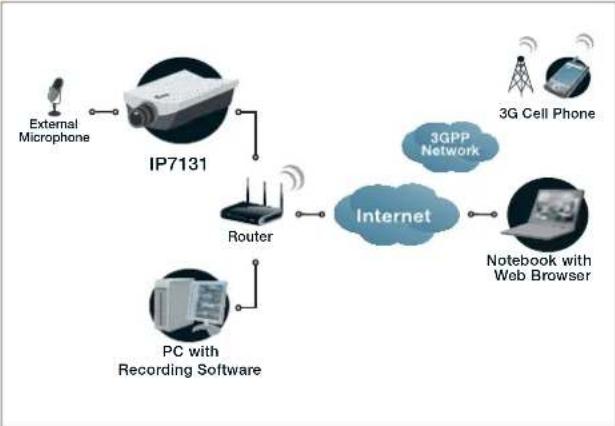
flowchart
graph TD
    A["External Microphone"] --> B["IP7131"]
    B --> C["Router"]
    C --> D["Internet"]
    D --> E["3G Cell Phone"]
    D --> F["Notebook with Web Browser"]
    C --> G["PC with Recording Software"]
External View
text_image
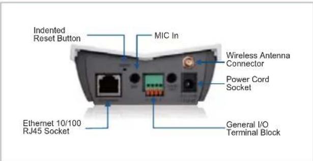
Indented Reset Button MIC In Wireless Antenna Connector Power Cord Socket Ethernet 10/100 RJ45 Socket General I/O Terminal BlockAccessories
text_image
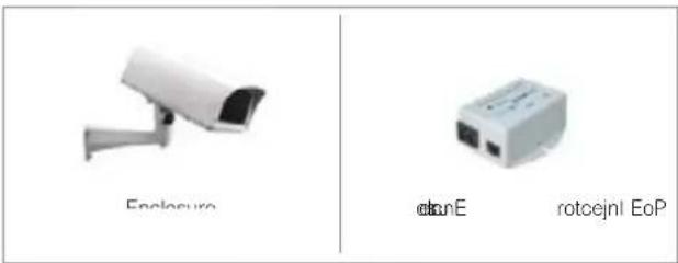
Enclosure otnE rotcejni EoPAll specifications are subject to change without notice. Copyright ©2009 VIVOTEK INC. All rights reserved.
Technology License Notice
MPEG-4 AAC Technology
THIS PRODUCT IS LICENSED UNDER THE MPEG-4 AAC AUDIO PATENT LICENSE. THIS PRODUCT MAY NOT BE DECOMPILED, REVERSE-ENGINEERED OR COPIED, EXCEPT REGARD TO PC SOFTWARE, YOU MAY MAKE SINGLE COPIES FOR ARCHIVAL PURPOSES. FOR MORE INFORMATION, PLEASE REFER TO HTTP://WWW.VIALICENSING.COM.
MPEG-4 Visual Technology
THIS PRODUCT IS LICENSED UNDER THE MPEG-4 VISUAL PATENT PORTFOLIO LICENSE FOR THE PERSONAL AND NON-COMMERCIAL USE OF A CONSUMER FOR (i) ENCODING VIDEO IN COMPLIANCE WITH THE MPEG-4 VISUAL STANDARD ("MPEG-4 VIDEO") AND/OR (ii) DECODING MPEG-4 VIDEO THAT WAS ENCODED BY A CONSUMER ENGAGED IN A PERSONAL AND NON-COMMERCIAL ACTIVITY AND/OR WAS OBTAINED FROM A VIDEO PROVIDER LICENSED BY MPEG LA TO PROVIDE MPEG-4 VIDEO. NO LICENSE IS GRANTED OR SHALL BE IMPLIED FOR ANY OTHER USE. ADDITIONAL INFORMATION INCLUDING THAT RELATING TO PROMOTIONAL, INTERNAL AND COMMERCIAL USES AND LICENSING MAY BE OBTAINED FROM MPEG LA, LLC. SEE HTTP://WWW.MPEGLA.COM.
AMR-NB Standard
THIS PRODUCT IS LICENSED UNDER THE AMR-NB STANDARD PATENT LICENSE AGREEMENT. WITH RESPECT TO THE USE OF THIS PRODUCT, THE FOLLOWING LICENSORS' PATENTS MAY APPLY:
TELEFONAKIEBOLAGET ERICSSON AB: US PAT. 6192335; 6275798; 6029125; 6424938; 6058359. NOKIA CORPORATION: US PAT. 5946651; 6199035. VOICEAGE CORPORATION: AT PAT. 0516621; BE PAT. 0516621; CA PAT. 2010830; CH PAT. 0516621; DE PAT. 0516621; DK PAT. 0516621; ES PAT. 0516621; FR PAT. 0516621; GB PAT. 0516621; GR PAT. 0516621; IT PAT. 0516621; LI PAT. 0516621; LU PAT. 0516621; NL PAT. 0516621; SE PAT 0516621; US PAT 5444816; AT PAT. 819303/AT E 198805T1; AU PAT. 697256; BE PAT. 819303; BR PAT. 9604838-7; CA PAT. 2216315; CH PAT. 819303; CN PAT. ZL96193827.7; DE PAT. 819303/DE69611607T2; DK PAT. 819303; ES PAT. 819303; EP PAT. 819303; FR PAT. 819303; GB PAT. 819303; IT PAT. 819303; JP PAT. APP. 8-529817; NL PAT. 819303; SE PAT. 819303; US PAT. 5664053. THE LIST MAY BE UPDATED FROM TIME TO TIME BY LICENSORS AND A CURRENT VERSION OF WHICH IS AVAILABLE ON LICENSOR'S WEBSITE AT HTTP://WWW.VOICEAGE.COM.
Electromagnetic Compatibility (EMC)
FCC Statement
This device compiles with FCC Rules Part 15. Operation is subject to the following two conditions.
■ This device may not cause harmful interference, and
■ This device must accept any interference received, including interference that may cause undesired operation.
This equipment has been tested and found to comply with the limits for a Class B digital device, pursuant to Part 15 of the FCC Rules. These limits are designed to provide reasonable protection against harmful interference in a residential installation. This equipment generates, uses and can radiate radio frequency energy and, if not installed and used in accordance with the instructions, may cause harmful interference to radio communications. However, there is no guarantee that interference will not occur in a partial installation. If this equipment does cause harmful interference to radio or television reception, which can be determined by turning the equipment off and on, the user is encouraged to try to correct the interference by one or more of the following measures:
■ Reorient or relocate the receiving antenna.
■ Increase the separation between the equipment and receiver.
■ Connect the equipment into an outlet on a circuit different from that to which the receiver is connected.
■ Consult the dealer or an experienced radio/TV technician for help.
Shielded interface cables must be used in order to comply with emission limits.
CE Mark Warning CE
This is a Class B product. In a domestic environment, this product may cause radio interference, in which case the user may be required to take adequate measures.
Liability
VIVOTEK Inc. cannot be held responsible for any technical or typographical errors and reserves the right to make changes to the product and manuals without prior notice. VIVOTEK Inc. makes no warranty of any kind with regard to the material contained within this document, including, but not limited to, the implied warranties of merchantability and fitness for any particular purpose.