BioStation T2 - Access Control System Suprema - Free user manual and instructions
Find the device manual for free BioStation T2 Suprema in PDF.


User questions about BioStation T2 Suprema
0 question about this device. Answer the ones you know or ask your own.
Ask a new question about this device
Download the instructions for your Access Control System in PDF format for free! Find your manual BioStation T2 - Suprema and take your electronic device back in hand. On this page are published all the documents necessary for the use of your device. BioStation T2 by Suprema.
USER MANUAL BioStation T2 Suprema
BioStation T2 is the IP network-based premium fingerprint verification terminal that delivers various authentication modes such as fingerprint, RFID, and PIN authentication for access control and time & attendance.
Features
| 5 inch touchscreen LCD |  | An intuitive GUI provided on the high-durable 5 inch touchscreen LCD delivers easy user management and displays various information and notices. |
| Camera for face image capture |  | The built-in high-performance camera detects the face image and captures image logs which delivers enhance security through valid identification check. |
| Embedded Web Server |  | The embedded web server (BioStar Lite) allows administrators to manage users and devices through a web browser in any PC without S/W and database installation. |
| Fast matching speed |  | Loaded with world's best performing Suprema fingerprint algorithm and powerful dual CPU achieves unparalleled 1:3,000 fingerprint matches in less than a second. |
| Versatile Interfaces |  | Provides various interfaces, such as PoE, WiFi, TCP/IP, and RS485/232, allowing users to connect to PCs and configure the network. In addition, Wiegand and I/O ports allow users to configure various access control systems. |
| Video Phone |  | Provides IP-based AV interface and analog video phone functions. |
| RF Card Options |  | Supports EM, Mifare Classic, Mifare Plus, and Mifare DesFire(CSN) cards. |
These safety instructions provided here are meant to guard your safety and prevent any possible damage or loss of property. Please carefully read these and keep them in mind when you use Suprema's product.
Safety Instructions

Do not install the terminal in a place affected by direct sunlight, humidity, dust, or soot.

Keep the terminal away from magnets or anything containing magnetic material, such as magnet, TV sets, computer monitor (especially CRT) and speakers.

Keep the terminal away from any heating devices or heat sources.

Do not spill any liquids such as soda, water, or solutions into the terminal.

Use a soft cloth or towel when cleaning the terminal. Do not spray water on the terminal.

Clean the terminal regularly to prevent dust from settling onto it.

Do not drop the terminal or cause any impact on the terminal.

Do not apply heavy pressure to the touch screen.

Do not disassemble, repair, or reconstruct the terminal without any direction of Suprema. Otherwise, you cannot receive proper A/S for the terminal from Suprema.

Keep the product out of reach from children for safety purposes.

Do not use the terminal for any other purpose than its original use.

In case of product malfunction or problems, please contact Suprema's Customer Service Center or the sales agent.
Table of Contents
1 Before Getting Started....6
Components 7
■ Basic Components....7
■ Optional Accessories ....8
Names and Functions of Parts 9
■ Front....9
■ Bottom....10
■ Rear....10
Dimensions 11
Menu Screen 12
Standby Screen 13
Authentication Mode 14
How to place a finger.... 15
2 Installation 17
Installation....18
Connector/Cable Specifications 19
■ 232 CABLE (3-pin Connector)....19
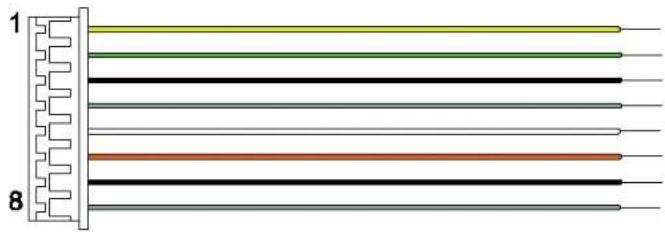
■ SWITCH CABLE (8-pin Connector)....19
■ RELAY CABLE (3-pin Connector)....20
■ WIEGAND CABLE (5-pin Connector)....20
■ POWER CABLE (2-pin Connector) 20
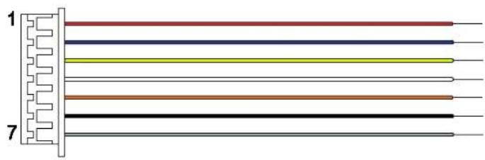
■ VIDEO PHONE CABLE (7-pin Connector) 21
■ RS485 CABLE (4-pin Connector) 21
Connection....22
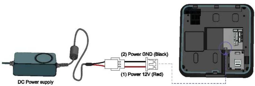
■ Power Connection (2-pin Connector)....22
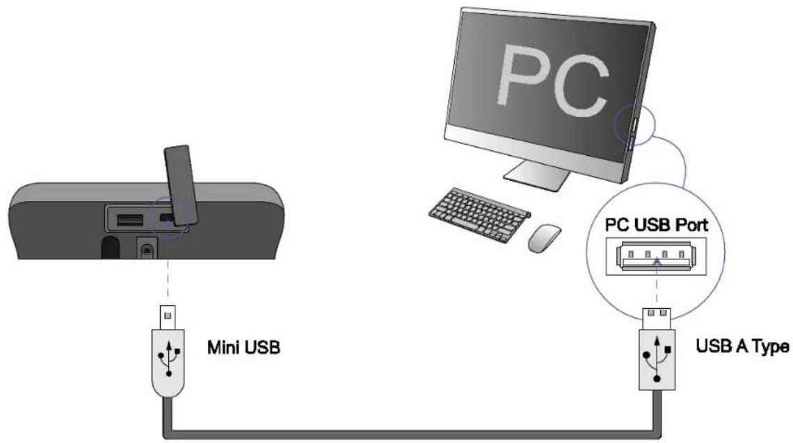
■ USB Cable Connection ....23
■ Ethernet Connection (Ethernet Cable)....24
■ Ethernet Connection (Direct connection to PC)....25
■ PoE hub connection....26
■ Wireless Connection ....27
■ USB Memory Connection....28
■ RS485 PC Connection (4-pin Connector)....29
■ RS485 Connection to Secure I/O or Other Terminals (4-pin Connector)....30
■ RS232 Connection....31
■ Videophone Connection....32
■ Relay Connection - Fail Safe Lock (3-pin Connector) .....33
■ Relay Connection - Fail Secure Lock (3-pin Connector) ....33
■ Relay Connection – Automatic Door (3-pin Connector) .....35
■ TTL Switch Input Connection (8-pin Connector)......36
■ Wiegand Input (5-pin Connector)....37
■ Wiegand Output (5-pin Connector)....37
System Configuration....38
■ Standalone ....38
■ Secured 38
■ Network Configuration....39
3 User Menu ....40
Access Authentication....41
Fingerprint Authentication 41
■ Fingerprint Only 41
■ Fingerprint + Pin Authentication....41
■ T&A Key+Fingerprint Authentication 42
■ T&A Key + Fingerprint + Pin Authentication....42
Card Authentication 42
■ Card Only Authentication 42
■ Card + Password Authentication....43
■ Card + Fingerprint Authentication ....43
■ Card + Fingerprint/Password Authentication .... 44
■ Card + Fingerprint + Password Authentication ....44
ID Authentication 45
■ ID + Password Authentication....45
■ ID + Fingerprint Authentication 45
■ ID + Fingerprint/Password Authentication ....46
■ ID + Fingerprint + Password Authentication ....46
T&A Mode 47
■ T&A Mode Setup 47
■ T&A Authenticate Methods....48
■ T&A Event 48
■ Personal Entrance/T&A Record Check....48
Authentication Failures 49
4 Admin Menu....50
Registering an Admin....51
■ Entering into Admin Menu....52
■ Configuration of Admin Menu....53
User Enrollment process....55
Registering User to Device (using CSN) 56
■ Enroll User ....57
■ Edit/Delete User ....60
■ Search User ....61
■ Checking the Registered User Info 62
■ Deleting All Users....62
Registering a User to a Card (using Template Card)....63
■ Issuing a Card....63
■ Formatting a Card....64
Network Setup 65
■ TCP/IP Setup 65
■ Server Setup 66
■ Serial Communication....66
■ USB....67
■ USB Memory....67
■ Wireless LAN 68
Authentication Mode 69
■ Finger Auth Mode....69
■ Card Auth Mode 69
■ ID Auth Mode ....70
■ Operation....70
■ T&A Mode ....71
■ T&A Event 72
■ Camera Event....72
Device Setup 73
■ Fingerprint Setting....73
■ Door 74
■ Interphone Setting....75
■ Date & Time Setup....76
■ Device Info 76
■ Memory Info 76
■ Touchscreen Calibration ....77
■ Touchkeypad Calibration....77
■ Reset....77
■ Factory Default....77
Display Setup....78
Log 79
■ Log List....79
■ Log Search....79
■ Delete All Log....80
■ Log Info 80
5 Appendix 81
Product Specifications 82
Electrical Specification....83
1 Before Getting Started
Please check the package and ensure that all of the components are prepared.
Components
Basic Components
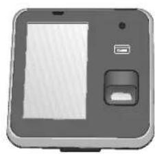
natural_image
Illustration of a handheld device with a screen and control panel (no text or symbols)BioStation T2 Body
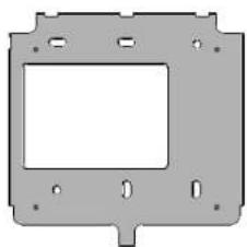
natural_image
Pure technical diagram of a mechanical part with mounting holes and central cavity (no text or symbols)Wall Bracket
Software CD (1 copy)
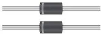
Diodes (2 EA)
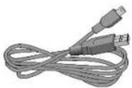
Mini USB Cable
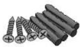
Screws and PVC Anchors (4 EA each)

Ferrite Core
natural_image
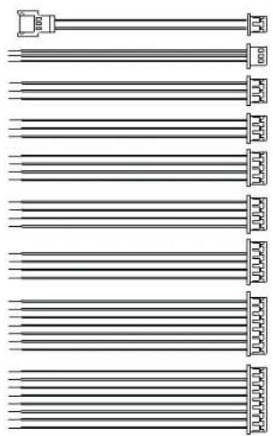
Pure electrical circuit lines without any symbolsCables (7 types, 9 EA)
Optional Accessories
natural_image
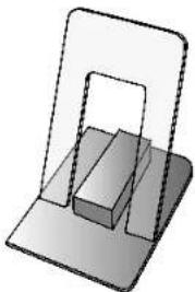
3D diagram of a rectangular block placed on a base platform, with no visible text or symbolsPlastic Stand
natural_image
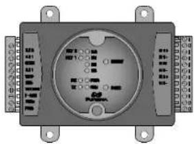
Electrical control panel with indicator lights and terminal blocks (no visible text or symbols)Secure I/O
natural_image
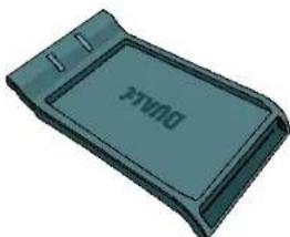
3D rendered image of a gray rectangular electronic device with 'DAKE' branding on the side (no other text or symbols)USB Mifare Reader/Writer
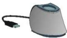
USB fingerprint scanner (for enrollment on PC)

Access Point
(For Wireless Model only)
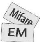
RF Cards
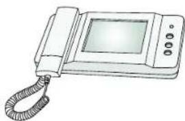
natural_image
Line drawing of a classic telegraph telephone with a cord and keypad (no text or symbols)Analog Video Phone
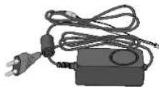
Power Adapter
Note
The product shown above is just an image to illustrate the product. Depending on Suprema's internal changes, some of the components shown here may be different and changed from the components that you have received.
Names and Functions of Parts
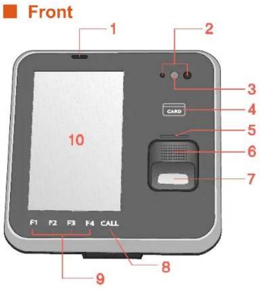
text_image
Front 1 2 3 4 5 6 7 10 CARD F1 F2 F3 F4 CALL 8 9No. Name Function
| 1 | Microphone | Used for interphone call. |
| 2 | Proximity Sensor | A sensor that detects objects around the device without any physical contact. To reduce power consumption, BioStation T2 lowers the brightness of the backlight when no input is made for a specified time. |
| 3 | Camera | Used for still image logs and video interphone. |
| 4 | Card reader Reads a RF card. | |
| 5 | Fingerprint Sensor LED | Displays the status of the fingerprint sensor.1)ON – Waiting for fingerprint input2)Blinking – Requesting for a specific fingerprint or fingerprint for registration |
| 6 | Speaker | Outputs sound effects and voices. |
| 7 | Fingerprint Sensor | Used to register and authenticate a user's fingerprint. |
| 8 | CALL Key | Used to make a call when a video phone is connected. |
| 9 | T&A Keys (F1~F4) | Used as function keys to select the T&A event |
| 10 | Color LCD Screen | Displays time, status, and UI for operation. |
Bottom
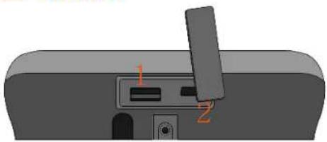
natural_image
3D diagram of a device with labeled ports (no text or symbols beyond numbers 1 and 2)Rear
text_image
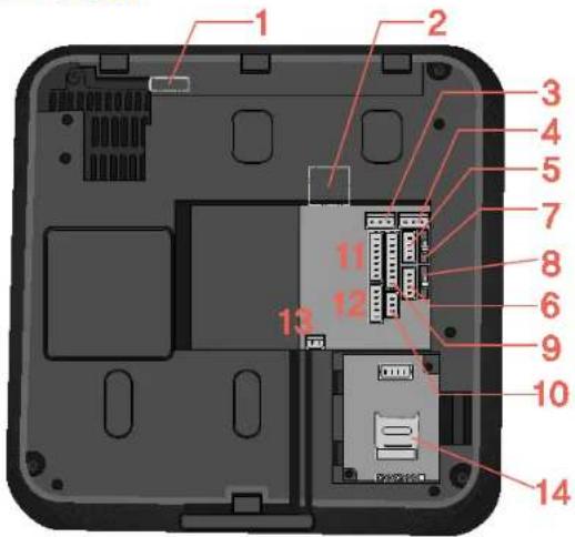
1 2 3 4 5 7 8 6 9 10 11 12 13 14*RS485-0: PC Connect
*RS485-1: RS485 Host/Slave
No. Name Function
| 1 | USB type A | A slot to connect a USB memory |
| 2 | Mini USB | A slot to connect a PC to a USB. |
No. Name Function
| 1 | USB Wireless LAN port | A slot to connect the USB wireless LAN device. For the wireless LAN-supported BioStation T2 model, the wireless LAN device is mounted before released from the factory. |
| 2 | RJ45 Socket Connects Ethernet cable | |
| 3, 4 | 3-pin Connector | Connects RELAY(0,1) |
| 5, 6 | 4-pin Connector | Connects RS485(0,1)* |
| 7, 8 | Termination Switch | RS485 TERMINATION Enable/Disable |
| 9 | 8-pin Connector | SWITCH Input |
| 10 | 3-pin Connector | Connects RS232 port |
| 11 | 7-pin Connector | Connects VIDEOPHONE |
| 12 | 5-pin Connector | WIEGAND Input/Output |
| 13 | 2-pin Connector | Connects power supply |
| 14 | Slot for Micro SD Memory Card | Used to insert Micro SD-type memory card for extended functions. |
Dimensions
155mm(W) x 155mm(H) x 40mm(D)
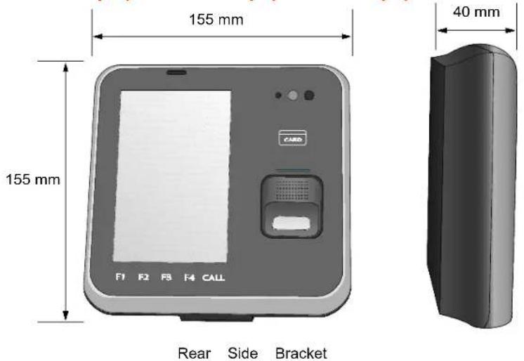
text_image
155 mm 155 mm F1 F2 F3 F4 CALL 40 mm Rear Side Bracket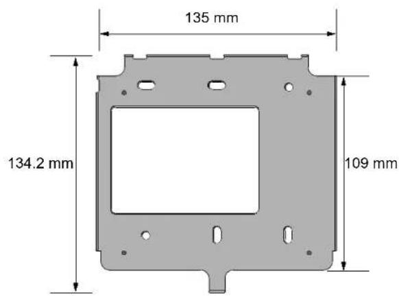
text_image
135 mm 134.2 mm 109 mmMenu Screen
text_image
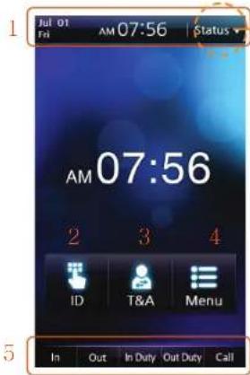
Jul 01 Fri AM 07:56 Status AM 07:56 2 3 4 ID T&A Menu In Out In Duty Out Duty Call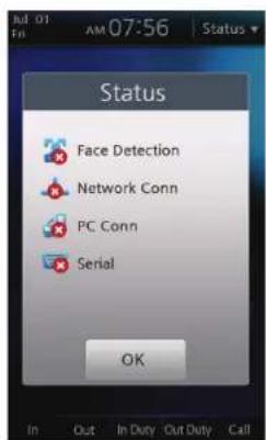
text_image
Status Face Detection Network Conn PC Conn Serial OK In Out In Duty Out Duty Call1 Status Bar: Displays the current date, time, and status icons.
2 ID: Enters the user ID for authentication.
3 T&A: Enters the additional T&A events.
4 Menu: Enters the administrator menu.
5 T&A Key Display: Describes operations of F1\~F4, CALL keys. The buttons work like F1\~F4, CALL keys.
1
2
3
4
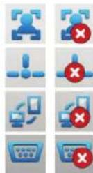
Displays whether or not to use face detection option for image logs.
Displays Ethernet connection status and wireless LAN connection status.
Displays connection to PC via Ethernet and wireless LAN.
Displays RS485 connection.
Standby Screen
Start-up Screen
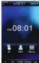
Theme 1
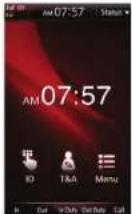
Theme 2
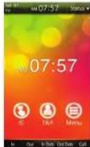
Theme 3
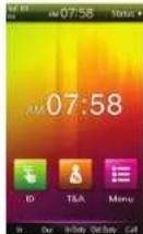
Theme 4
Note
When time is hidden from the center of the screen for Theme 1 and Theme 3, the moving background screen is displayed.
T&A Configuration
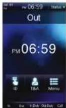
The T&A event is displayed under the status bar.
Setting the Background Screen
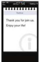
Notice

Slide

PDF
Other Standby Screens
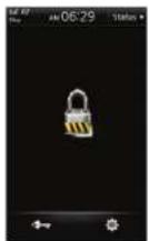
Locked: You can lock the terminal using the tampers position or a specific input port. To unlock the terminal, administrator's authentication is required.
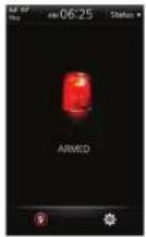
Armed: When a security area is set, you can change the mode of the terminal to the security mode. To release the security mode, authentication by a user who belongs to the corresponding security group is required. For more details, see the BioStar manual.
Authentication Mode
BioStation T2 supports various authentication modes using fingerprints, RFID card, and ID (PIN).
| Fingerprint Authentication Mode | Card Authentication Mode | ID Authentication Mode |
| ■ Finger:Only fingerprints are used for authentication.■ Finger+Pin:For authentication, input the fingerprint and then type the password. | ■ Card Only:Only a RF card is used for authentication.■ Card+Pin:For authentication, place the registered card onto the card reader and then type the password.■ Card+Finger:For authentication, place the registered card onto the card reader and then input the fingerprint.■ Card+Finger/Pin:For authentication, place the registered card onto the card reader and then input the fingerprint or type the password.■ Card+Finger+Pin:For authentication, place the registered card onto the card reader, and then input the fingerprint and type the password. | ■ ID+Pin:For authentication, type the registered ID and then type the password.■ ID+Finger:For authentication, type the registered ID and then input the fingerprint.■ ID+Finger/Pin:For authentication, type the registered ID and then input the fingerprint or type the password.■ ID+Finger+Pin:For authentication, type the registered ID, and then input the fingerprint and type the password. |
Note
For more detailed description on each authentication mode, see [Chapter 3, User Menu > Access Authentication (p.40)].
How to place a finger
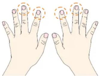
Select a finger to enroll
natural_image
Illustration of two human hands with finger positions and orange circular annotations (no text or symbols)(1) It is recommended to use an index finger or a middle finger.
(2) Thumb, ring or little finger is relatively more difficult to place in a correct position.
How to place a finger on a sensor
(1) Place a finger as it completely covers the sensor with maximum contact.
(2) It is better to place the core part of a fingerprint to the center of a sensor.
● People usually tend to place only the top end of a finger
● Where is the core (center) of a fingerprint?
■ A peak where spirals of fingerprint ridges are dense
■ Usually opposite to lower part of a nail
■ It is recommended to place a finger as the lower part of a nail is located at the center of a sensor
(3) If a finger is placed as in the right picture, only a small area of a finger is captured. So it is recommended to place a finger as in the left picture.
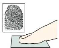
Right
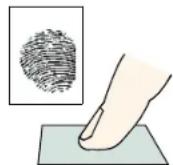
Wrong
■ Tips for different finger conditions
Suprema's fingerprint products are designed to scan fingerprint smoothly regardless of the conditions of a finger skin. However, if a fingerprint is difficult to scan due to other influences, please refer to the followings tips.
(1) If a finger is stained with sweat or water, scan after wiping moisture off.
(2) If a finger is covered with dust or impurities, scan after wiping them off.
(3) If a finger is way too dry, scan after blowing warm breath on a fingertip.
■ Advices on fingerprint enrollment
(1) In fingerprint recognition, enrollment process is very important. Therefore, when enrolling a fingerprint, please try to place a finger correctly with care.
(2) In case of low acceptance ratio, the following actions are recommended.
- Delete enrolled fingerprints and re-enroll the fingers.
● Enroll the same finger additionally - Try with another finger if a finger is not easy to enroll due to scar or worn-out.
(3) For the case when an enrolled fingerprint can't be used due to scar or holding a baggage, it is recommended to enroll more than two fingers.
2 Installation
Installation
BioStation T2 has a camera for face detection and video interphone. Therefore, height of the product and its camera angle are very important factors in installation. For easy face detection and fingerprint authentication, determine the place where the product should be installed. We recommend you to install the product at the height of 130 cm \~ 140 cm from the floor and the minimum distance between the product and the human is 40 cm.
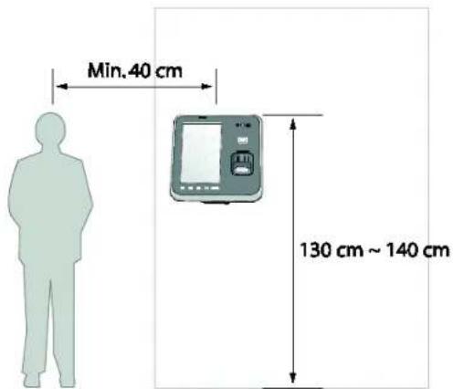
text_image
Min. 40 cm 130 cm ~ 140 cm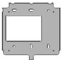
- Adjust the wall mounted bracket to the desired place on the wall and then fix it firmly to the wall.
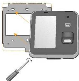
natural_image
Illustration of a device with a screwdriver inserted, showing internal components and a close-up view (no text or symbols)- Attach the product on the fixed wall mounted bracket and fix it to the bracket using the screw located at the bottom of the wall mounted bracket.
Connector/Cable Specifications
■ 232 CABLE (3-pin Connector)
| Pin | Name | Cable Type | Color |
| 1 232 RX | AWG26 | GREEN | |
| 2 232 TX YELLOW | |||
| 3 232 GND BLACK | |||

natural_image
Pure electrical connector diagram with three colored wires (green, yellow, black) and a terminal block, no text or symbols present.SWITCH CABLE (8-pin Connector)
| Pin | Name | Cable Type | Color |
| 1 TTL IN0 | AWG26 | YELLOW | |
| 2 TTL IN1 GREEN | |||
| 3 TTL GND BLACK | |||
| 4 | SH GND | GRAY | |
| 5 | TTL IN2 | WHITE | |
| 6 | TTL IN3 | ORANGE | |
| 7 TTL GND BLACK | |||
| 8 | SH GND | GRAY | |
natural_image
Pure electrical circuit lines without any symbols■ RELAY CABLE (3-pin Connector)
| Pin | Name | Cable Type | Color |
| 1 RLY NO | AWG24 | WHITE | |
| 2 RLY COM BLUE | |||
| 3 RLY NC ORANGE | |||
WIEGAND CABLE (5-pin Connector)
| Pin | Name | Cable Type | Color |
| 1 WG D0 | AWG26 | GREEN | |
| 2 WG D1 WHITE | |||
| 3 WG GND BLACK | |||
| 4 | SH GND | GRAY | |
■ POWER CABLE (2-pin Connector)
| Pin | Name | Cable Type | Color |
| 1 | PWR +VDC | AWG24 | RED |
| 2 | PWR GND | BLACK |

natural_image
Pure electrical circuit lines without any symbols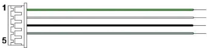
natural_image
Pure electrical circuit lines without any symbols
natural_image
Pure electrical connector diagram showing two terminals connected by a red and black line (no text or symbols)■ VIDEO PHONE CABLE (7-pin Connector)
| Pin | Name | Cable Type | Color |
| 1 VP VOC | AWG26 | RED | |
| 2 | VP GND | BLUE | |
| 3 VP +VDC YELLOW | |||
| 4 VP VS WHITE | |||
| 5 VP DOS ORANGE | |||
| 6 | VP GND | BLACK | |
| 7 SH GND GRAY | |||
natural_image
Pure electrical circuit lines without any symbolsRS485 CABLE (4-pin Connector)
| Pin | Name | Cable Type | Color |
| 1 | 485 TRXP | AWG26 | BLUE |
| 2 | 485 TRXN | YELLOW | |
| 3 | 485 GND | BLACK | |
| 4 SH | GND GRAY |

natural_image
Pure electrical connector diagram without any text or symbolsConnection
■ Power Connection (2-pin Connector)
text_image
DC Power supply (2) Power GND (Black) (1) Power 12V (Red)| Note | Recommended Power Specification- You should use a 12V adapter which is covered by IEC/EN 60950-1, providing voltage of 12V ± 10% and a current of 1500mA or above.- It is recommended that the power of BioStation T2 shall not be shared with other devices such as Secure I/O and Lock. |
BioStation T2 User Guide
2 Installation
USB Cable Connection
flowchart
graph TD
    A["Mini USB"] --> B["PC USB Port"]
    B --> C["USB A Type"]
    style A fill:#f9f,stroke:#333
    style B fill:#ccf,stroke:#333
    style C fill:#cfc,stroke:#333
■ Ethernet Connection (Ethernet Cable)
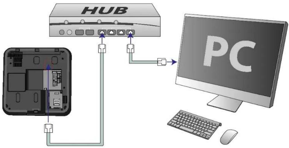
Connect the RJ45 socket on the rear of the product to the hub with an Ethernet (LAN) cable.
text_image
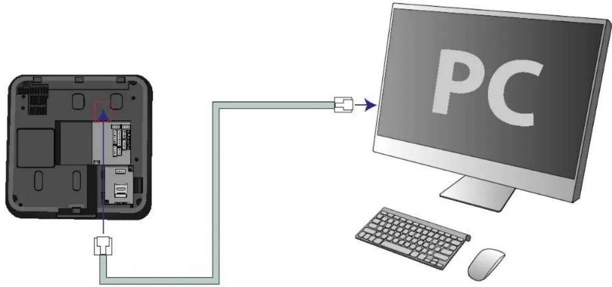
HUB PC- Ethernet Connection (Direct connection to PC)
text_image
PCPoE hub connection
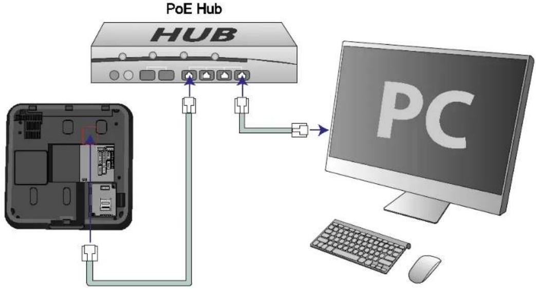
PoE (Power over Ethernet) is an Ethernet connection of which power is provided by IEEE802.3af standard-compliant PSE (Power sourcing Equipment).
text_image
PoE Hub HUB PCNote
If you use PoE, the length of a LAN cable should be within 100 m.
Wireless Connection
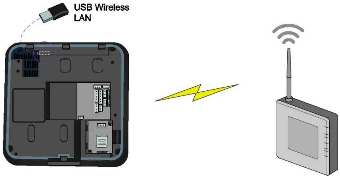
Wireless connection is made by mounting the USB wireless LAN module.
For the wireless LAN-supported BioStation T2, the wireless LAN device is mounted before released from the factory.
text_image
USB Wireless LANNote
The performance of a wireless LAN depends on the type of the AP (access point) and the environment.
Some wireless APs will not be fully compatible with the terminal so that the wireless LAN connection may not be successful.
The wireless APs listed below are fully compatible with the BioStation T2.
Buffalo WHR-HP-C54
IP Time G104
USB Memory Connection
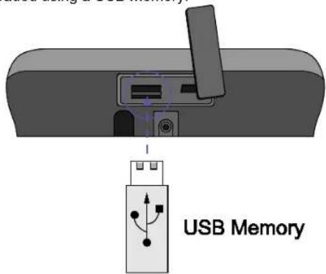
User data or log data can be downloaded/uploaded using a USB memory.
text_image
USB Memory| Note | Some USB memories will not be fully compatible with the terminal so that the connection may not be successful. The USB memories listed below are fully compatible with the BioStation T2.■ [IMATION] Flash Drive Nano 4GB■ [LG Electronics] X TICK M4 4GB■ [LG Electronics] X TICK MOBY J1 2GB■ [PQI] Traveling Disk U173 4GB■ [Samsung C&T Corporation] PLEOMAX PUB-S100 4GB■ [IMATION] Flash Drive Nano 4GB■ [LG Electronics] X TICK M4 4GB■ [LG Electronics] X TICK MOBY J1 2GB■ [PQI] Traveling Disk U173 4GB■ [Samsung C&T Corporation] PLEOMAX PUB-S100 4GB |
RS485 PC Connection (4-pin Connector)
flowchart
graph LR
    PC["PC"] --> TRX+[TRX-GND]
    TRX+ --> RS232["RS232-485 Converter"]
    RS232 --> CableShield["Cable shield(optional)"]
    CableShield --> BioStationT21["BioStation T2 Enable termination"]
    BioStationT21 --> SW2["SW2 TERM-1"]
    BioStationT21 --> SW1["SW1 TERM-0"]
    BioStationT2 --> SW2_1["TERM-1"]
    BioStationT2 --> SW1_1["TERM-0"]
    BioStationT2 --> SW2_2["SW2 TERM-1"]
    BioStationT2 --> SW1_2["SW1 TERM-0"]
    BioStationT2 --> SW2_3["SW2 TERM-1"]
    BioStationT2 --> SW1_3["SW1 TERM-0"]
    BioStationT2 --> SW2_4["SW2 TERM-1"]
    BioStationT2 --> SW1_4["SW1 TERM-0"]
*RS485-0: PC Connect
*RS485-1: RS485 Host/Slave
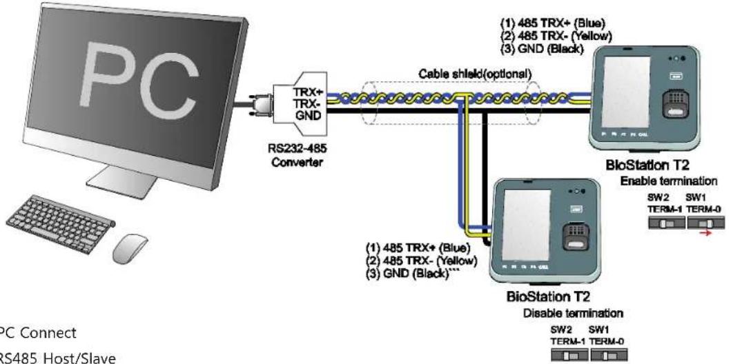
| Note | If the RS485 cable is too long, the signal may be weakened. In this case, you should install a terminating resistance at both ends of the bus by turning on the Dip Switch for normal signal transmission On the other hand, if the cable is too short, the resistance may interrupt signal transmission. Therefore, by considering the length of the cable and the signal status, select whether to turn on or off the terminating resistance switch. |
| Caution! | - Only the devices at the both ends of the bus should be terminated.- If you do not connect GND, the RS485 chip may be damaged or communication may not be successful. |
RS485 Connection to Secure I/O or Other Terminals (4-pin Connector)
flowchart
graph LR
    A["BioStation T2 (Host)"] -->|1) 485 TRX+ (Blue)
2) 485 TRX- (Yellow)
3) GND (Black)| B["BioStation T2 (Slave)"]
    B -->|1) 485 TRX+ (Blue)
2) 485 TRX- (Yellow)
3) GND (Black)| A
    A --> C["Secure I/O"]
    B --> D["Secure I/O"]
    C --> E["5-0: PC Connect"]
    D --> F["5-1: PS485 Host/Slave"]
*RS485-0: PC Connect
*RS485-1: RS485 Host/Slave
Note
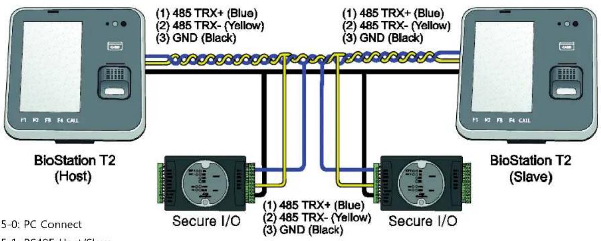
One RS485 network can be connected to 8 terminals in maximum, including a Host.
Caution!
If you do not connect GND, the RS485 chip may be damaged or communication may not be successful.
BioStation T2 User Guide
2 Installation
RS232 Connection
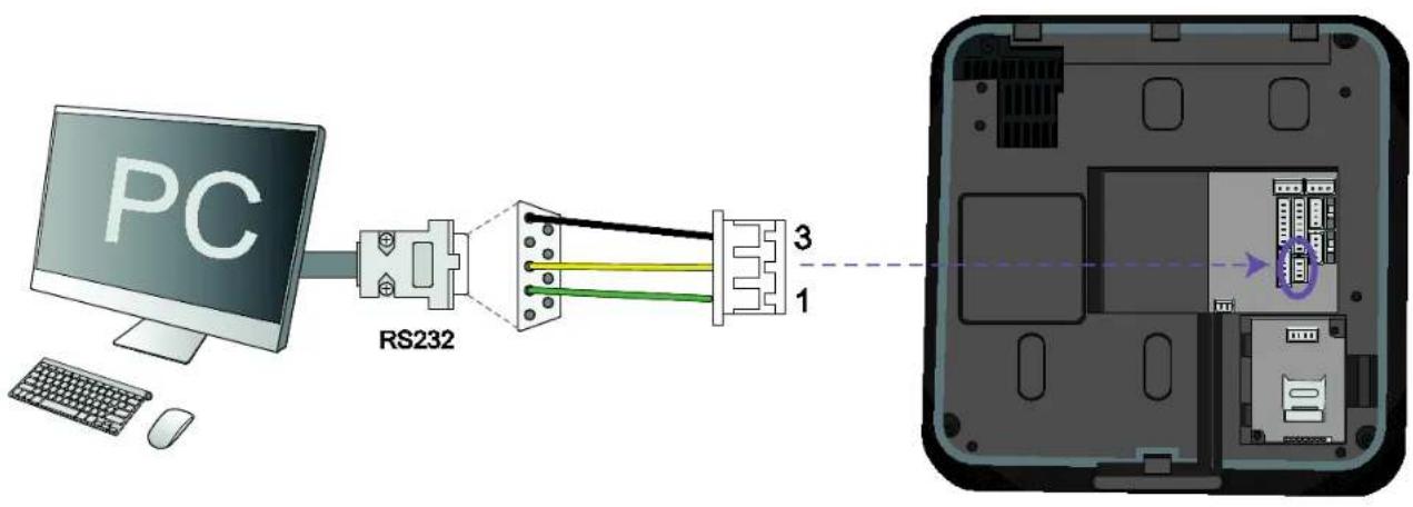
text_image
PC RS232 3 1BioStation T2 User Guide
2 Installation
■ Videophone Connection
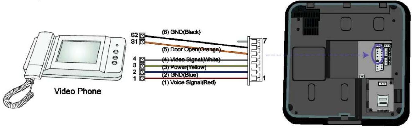
text_image
Video Phone S2 S1 (6) GND(Black) (5) Door Open(Orange) 4 (4) Video Signal(White) 3 (3) Power(Yellow) 2 (2) GND(Blue) 1 (1) Voice Signal(Red)| Note | The only following videophone models are compatible with BioStation T2.■ COMMAX / CAV-35N■ COMMAX / CAV-50H■ COMMAX / CAV-50P |
■ Relay Connection - Fail Safe Lock (3-pin Connector)
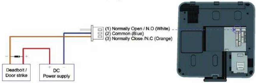
text_image
(1) Normally Open / N.O (White) (2) Common (Blue) (3) Normally Close /N.C (Orange)■ Relay Connection - Fail Secure Lock (3-pin Connector)
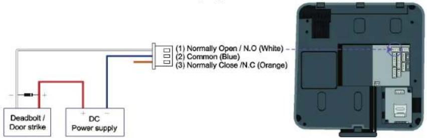
text_image
(1) Normally Open / N.O (White) (2) Common (Blue) (3) Normally Close /N.C (Orange)| Note | -N.O. (Normally Open): A control signal closes the circuit.-N.C. (Normally Closed): A control signal opens the circuit.-Take care of the direction of the diode.-Make sure to install the diode near to the door lock.-Make sure to use different power supplies for the BioStation T2 and the door lock.-Make sure to install the diode at both ends of the circuit as shown in the figures above in order to protect the relay contact from the reverse current that occurs when the door lock works. |
■ Relay Connection – Automatic Door (3-pin Connector)
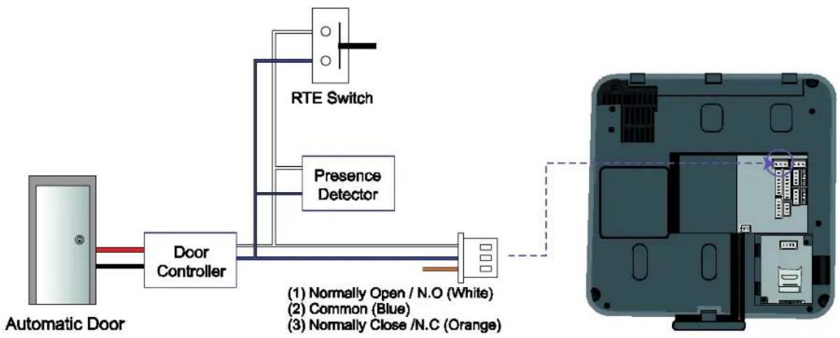
flowchart
graph LR
    A["Automatic Door"] --> B["Door Controller"]
    B --> C["RTE Switch"]
    B --> D["Presence Detector"]
    C --> E["(1) Normally Open / N.O (White)"]
    C --> F["(2) Common (Blue)"]
    C --> G["(3) Normally Close /N.C (Orange)"]
| Note | -Normally Open/N.O: When no control signal is received, the electricity does not flow. When control signals are received, the electricity continues flowing.-Normally Close/N.C: When no control signal is received, the electricity continues flowing. When control signals are received, the electricity does not flow. |
■ TTL Switch Input Connection (8-pin Connector)
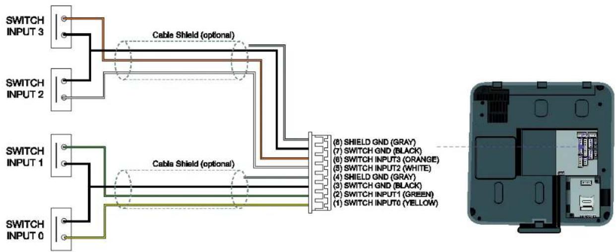
text_image
SWITCH INPUT 3 Cable Shield (optional) SWITCH INPUT 2 SWITCH INPUT 1 Cable Shield (optional) SWITCH INPUT 0 (8) SHIELD GND (GRAY) (7) SWITCH GND (BLACK) (6) SWITCH INPUT3 (ORANGE) (5) SWITCH INPUT2 (WHITE) (4) SHIELD GND (GRAY) (3) SWITCH GND (BLACK) (2) SWITCH INPUT1 (GREEN) (1) SWITCH INPUT0 (YELLOW)BioStation T2 User Guide
2 Installation
■ Wiegand Input (5-pin Connector)
■ Wiegand Output (5-pin Connector)
Note There is only one Wiegand port. Select either of Wiegand Output and Wiegand Input using BioStar software.
System Configuration
Standalone
A terminal works both of door control and authentication functions.
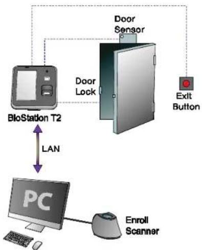
flowchart
graph TD
    A["BioStation T2"] -->|LAN| B["PC"]
    B --> C["Door Sensor"]
    C --> D["Exit Button"]
    C --> E["Computer"]
    B --> F["User"]
    B --> G["Computer"]
    style A fill:#f9f,stroke:#333
    style B fill:#ccf,stroke:#333
    style C fill:#cfc,stroke:#333
    style D fill:#fcc,stroke:#333
    style E fill:#cff,stroke:#333
    style F fill:#ffc,stroke:#333
    style G fill:#fcc,stroke:#333
Secured
A terminal works as authentication function. Secure I/O works as a door controller.
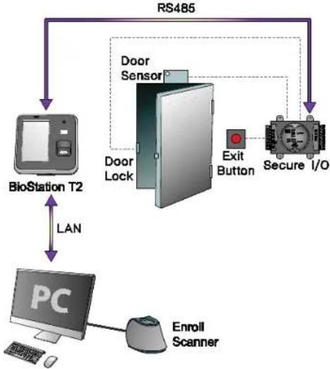
flowchart
graph TD
    A["BioStation T2"] -->|LAN| B["PC"]
    B --> C["Enroll Scanner"]
    C --> D["Door Lock"]
    D --> E["Door Sensor"]
    E --> F["Exit Button"]
    F --> G["Secure I/O"]
    G --> H["RS485"]
    H --> A
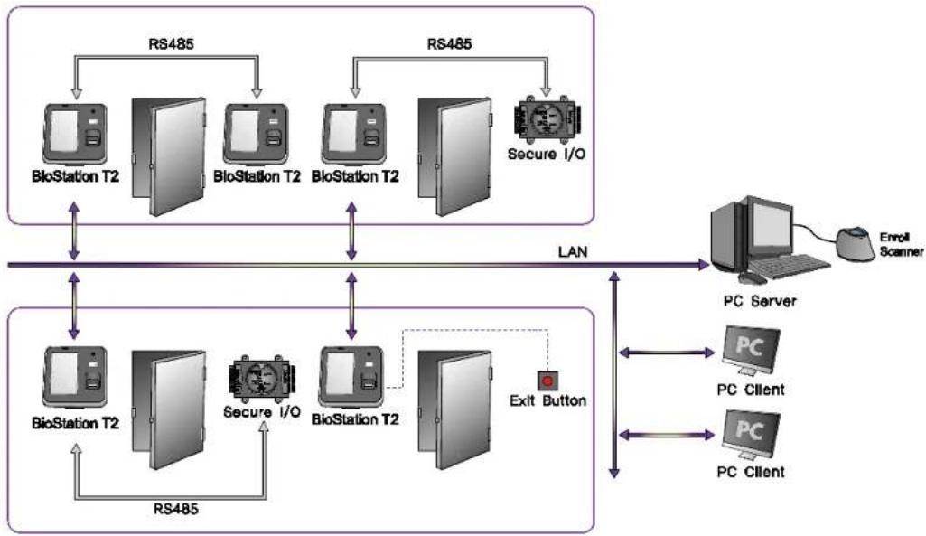
■ Network Configuration
LAN and RS485 allow integrated management.
flowchart
graph TD
    subgraph Top_Layer
        A["RS485"] --> B["BioStation T2"]
        A --> C["BioStation T2"]
        D["RS485"] --> E["BioStation T2"]
        D --> F["BioStation T2"]
        G["Secure I/O"] --> H["Secure I/O"]
    end

    subgraph Bottom_Layer
        I["BioStation T2"] --> J["RS485"]
        K["Secure I/O"] --> L["BioStation T2"]
        M["Exit Button"] --> N["PC Server"]
        O["PC Client"] --> P["PC Client"]
    end

    B <--> H
    E <--> L
    L <--> N
    N <--> P
    style Top_Layer fill:#f9f,stroke:#333
    style Bottom_Layer fill:#bbf,stroke:#333
    style Top_Layer fill:#dfd,stroke:#333
    style Bottom_Layer fill:#dfd,stroke:#333
3 User Menu
Access
Authentication
BioStation T2 supports three authentication types: fingerprint, Card(RFID), and ID(PIN). The authentication modes are operated in accordance with the set time schedule and the time schedule of each authentication means is not overlapped with the others. Up to 128 of time schedules can be set through BioStar software.
Fingerprint
■ Fingerprint Only
-
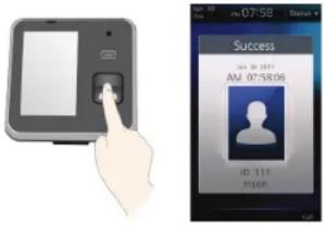
[Menu] > [Mode] > [Finger Auth Mode] > [Finger]
-
Select either of Always or the desired time schedule.
text_image
Image showing a hand interacting with a mobile device and a digital app interface displaying user information.1 Place a finger on the sensor.
2 An authentication success screen is displayed.
Note
The authentication success screen is then displayed only when the card authentication has succeeded.
- If the user's picture has been registered: he user's picture is then displayed on the authentication success screen.
- If the user's picture has not been registered: The recorded image is displayed. If the still image log has not been recorded, the default image is then displayed on the authentication success screen.
■ Fingerprint + Pin Authentication
- [Menu] > [Mode] > [Finger Auth Mode] > [Finger+Pin]
- Select either of Always or the desired time schedule.
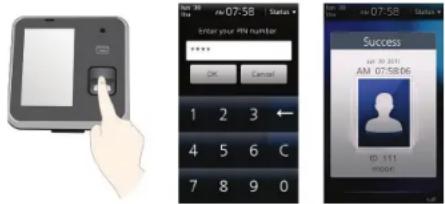
1 Place a finger on the sensor.
2 A PIN number input window appears.
Enter the password(PIN number) and then press [OK].
3 An authentication success screen is displayed.
■ T&A Key+Fingerprint Authentication
- [Menu] > [Mode] > [Finger Auth Mode] > [T&A Key+Finger]
- Select either of Always or the desired time schedule.
1 Press the desired T&A Key (F1\~F4).
2 Place a finger on the sensor.
3 An authentication success screen is displayed.
■ T&A Key + Fingerprint + Pin Authentication
- [Menu] > [Mode] > [Finger Auth Mode] > [T&A Key+Finger+Pin]
- Select either of Always or the desired time schedule.
1 Press the desired T&A Key (F1\~F4).
2 Place a finger on the sensor.
3 A PIN number input window appears.
Enter the password(PIN number) and then press [OK].
4 An authentication success screen is displayed.
Card
■ Card Only Authentication
Card Only authentication is enabled when the authentication mode is set to 'Card Only' status or the user's card has been registered as a Bypass card.
- [Menu] > [Mode] > [Card Auth Mode] > [Card Only]
- Select either of Always or the desired time schedule.
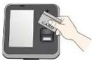
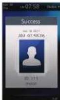
1 Place the card into the card reader.
2 An authentication success screen is displayed.
■ Card + Password Authentication
- [Menu] > [Mode] > [Card Auth Mode] > [Card+Pin]
- Select either of Always or the desired time schedule.
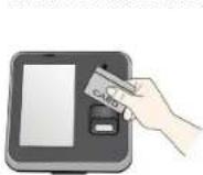
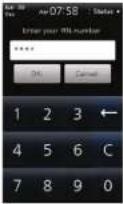

1 Place the card into the card reader.
2 A PIN number input window appears.
Enter the password(Pin number) and then press [OK].
3 An authentication success screen is displayed.
■ Card + Fingerprint Authentication
- [Menu] > [Mode] > [Card Auth Mode] > [Card+Finger]
- Select either of Always or the desired time schedule.
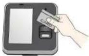
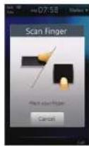
1 Place the card into the card reader.
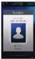
2 A fingerprint input window appears, place a finger on the sensor.
3 An authentication success screen is displayed.
■ Card + Fingerprint/Password Authentication
- [Menu] > [Mode] > [Card Auth Mode] > [Card+Finger/Pin]
- Select either of Always or the desired time schedule.
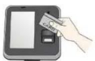
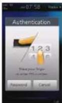
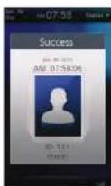
1 Place the card into the card reader.
2 Input the fingerprint or type the password.
3 An authentication success screen is displayed.
■ Card + Fingerprint + Password Authentication
- [Menu] > [Mode] > [Card Auth Mode] > [Card+Finger+Pin]
- Select either of Always or the desired time schedule.
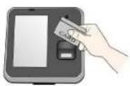
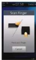
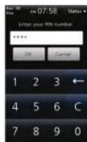
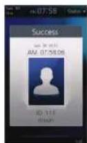
1 Place the card into the card reader.
2 A fingerprint input window appears, place a finger on the sensor.
3 A PIN number input window appears.
Enter the password(PIN number) and then press [OK].
4 An authentication success screen is displayed.
ID
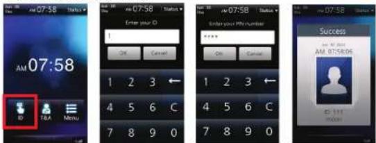
ID + Password Authentication
- [Menu] > [Mode] > [ID Auth Mode] > [ID+Pin]
- Select either of Always or the desired time schedule.
text_image
AM 07:58 ID T&A Menu Enter your ID 1 OK Cancel 1 2 3 4 5 6 C 7 8 9 0 Enter your Info number OK Cancel 1 2 3 4 5 6 C 7 8 9 0 Success AM 07:58/06 AM 07:58:06 ID: 111 mbox1 On the Standby Screen, press [ID].
2 An ID input window appears, Enter your ID.
3 A PIN number input window appears.
Enter the password(PIN number) and then press [OK].
4 An authentication success screen is displayed.
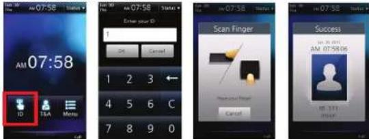
ID + Fingerprint Authentication
- [Menu] > [Mode] > [ID Auth Mode] > [ID+Finger]
- Select either of Always or the desired time schedule.
text_image
07:58 AM 07:58 ID T&A Menu Enter your ID 1 2 3 4 5 6 C 7 8 9 0 Scan Finger Cancel Success AM 07:58:06 ID 1011 MINT1 On the Standby Screen, press [ID].
2 An ID input window appears, Enter your ID.
3 A fingerprint input window appears. Place the finger on the scanner.
4 An authentication success screen is displayed.
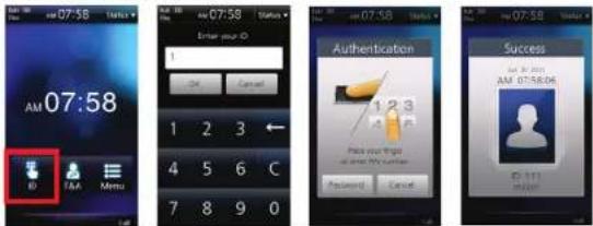
ID + Fingerprint/Password Authentication
- [Menu] > [Mode] > [ID Auth Mode] > [ID+Finger/Pin]
- Select either of Always or the desired time schedule.
text_image
AM 07:58 ID TAA Menu Enter your ID 1 2 3 4 5 6 C 7 8 9 0 Authentication 1 2 3 Pick your info Password Cancel Success AM 07:58:06 0:1111 On the Standby Screen, press [ID].
2 An ID input window appears, Enter your ID.
3 An Authentication window appears. Enter the password or place the finger on the scanner.
4 An authentication success screen is displayed.
ID + Fingerprint + Password Authentication
- [Menu] > [Mode] > [ID Auth Mode] > [ID+Finger+Pin]
- Select either of Always or the desired time schedule.
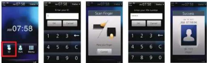
text_image
07:58 ID T&A Menu Enter your ID 1 2 3 4 5 6 C 7 8 9 0 Scan Finger Enter your RNA number 1 2 3 4 5 6 C 7 8 9 0 Success 07:58 AM 07:58:05 ID: 111 Cancel1 On the Standby Screen, press [ID].
2 An ID input window appears, Enter your ID.
3 A fingerprint input window appears, place a finger on the sensor.
4 A PIN number input window appears.
Enter the password(PIN number) and then press [OK].
5 An authentication success screen is displayed.
T&A Mode
T&A Mode Setup
1 [Menu] > [Mode] > [T&A Mode]
2 Select a desired T&A mode.
■ Manual(by key input)
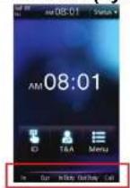
If the T&A mode is set to [Manual], press the F1 to F4 key or the extended T&A key to select a predefined T&A event. The selected T&A event is released after authentication.
■ Auto(by time schedule)
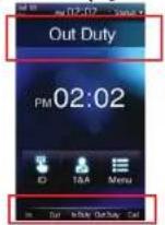
If the T&A mode is set to [Auto] mode, the pre-defined T&A event will be automatically applied in accordance with the specified time period which is set in BioStar. You can define T&A event and time period in BioStar. To change the current T&A event to another T&A event, press the T&A key to select the desired T&A event.
■ Manual Fix(by key input)
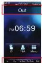
If the T&A mode is set to [Manual Fix] mode, you can select a T&A event like [Manual]. Press the F1 to F4 key or the extended T&A key to select a predefined T&A event. However, different from [Manual] mode, the once selected T&A event is kept until another T&A event is selected in [Manual Fix].
■ Fixed(by device)
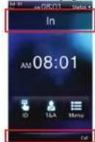
If the T&A mode is set to [Fixed] mode, authentication is available only with the fixed T&A event. You cannot select any other T&A event but the fixed one. You can define a fixed T&A event in BioStar.
■ Disabled
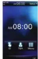
Select [Disabled] mode to use access authentication only without T&A management.
T&A Authenticate Methods
1 Press the F1 to F4 key or the corresponding T&A button on screen and select a desired T&A event. (Ignore this step at [Auto] or [Fixed] mode)
2 Proceed with authentication procedures. (identical with that of access authentication)
3 An authentication success window is then displayed and the T&A event is applied.
T&A Event
■ Basic T&A Events (F1\~F4)
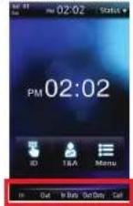
There are four basic T&A events. To select one of those, press the T&A button at the bottom of the screen or the F1 to F4 keys.
- In: Arrive at work.
● Out: Leave after work.
● In Duty: Return during work.
● Out Duty: Leave temporarily during work.
Additional T&A Event
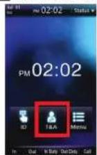
You can select the additional T& A events, predefined by the BioStar software.
To select the additional T&A event, press [T&A] button on the Start-up screen.
■ Personal Entrance/T&A Record Check
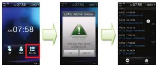
You can check your entrance/T&A records. To check it, follow the procedures below.
1 On the Standby screen, select [Menu].
2 Place the finger or the card or press [ID] and enter the ID.
3 You can check your entrance/T&A records.
Note
The personal entrance/T&A record check is for the general users only. Administrators can enter into Admin Menu using the above procedures. (See p.51)
Authentication Failures
| Access denied | I Displayed when authentication is failed. |
| Auth Mode Error | I Displayed when the authentication mode does not match up. |
| Invalid time interval | I Displayed when authentication is limited by authentication interval limit. |
| Exceeded count | I Displayed when the number of authentications exceeds the specified authentication count. |
| Access is not granted | I Displayed when the user does not belong to the Access Group. |
| Anti-passback failed | I Displayed when the access is limited by Anti-passback. |
| Unregistered User | I Displayed when the user is an unregistered user or the user information is not saved in the data card. |
4 Admin Menu
Registering an Admin
There is no registered user data in the product delivered from the factory.
Please register the administrator immediately after the first installation of BioStation T2. The Admin can add/delete users and configure terminal settings.
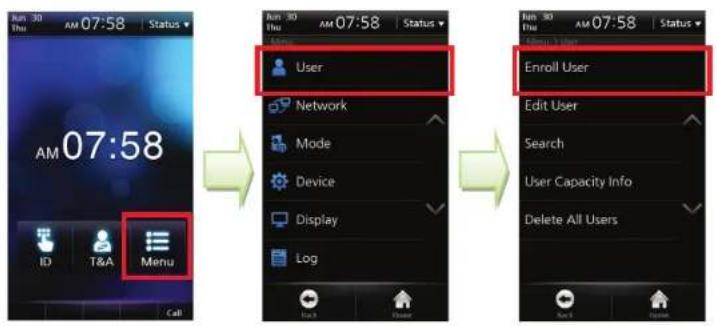
1 Select [Menu] > [User] > [Enroll User].
2 Enter the user ID and at least one of card information, password, and fingerprints.
3 Check the Admin Level checkbox and then press [Save] button.
User Info Items
| Face |
| User ID |
| Name |
| Fingerprint |
| Card |
| Password |
| Administrator |
| Duress Finger |
| Bypass Card |
| Individual Auth |
Access Group
Note
The admin registration procedure is identical with that of user registration except the [Admin Level] checkbox. Please see the user registration pages. (p.55\~p.58)
■ Entering into Admin Menu
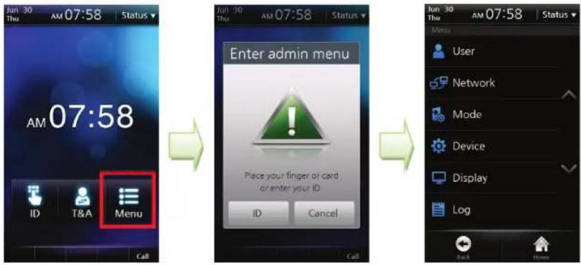
1 On the main screen, press [Menu].
2 The [Enter Admin menu] screen is displayed.
3 Place the card close to the card reader on the terminal or press [ID] and enter the ID.
4 If required, enter the password and click [OK].
5 The Admin Menu is displayed.
Note
- If no user has been registered and you press [Menu], you will enter into the Admin Menu without any authentication procedures.
- The general user, not the administrator, enters into his/her entrance/T&A log check screen. (See p.47)
Configuration of Admin Menu
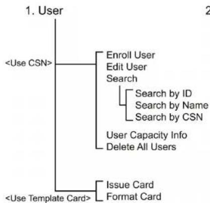
flowchart
graph TD
    A["1. User"] --> B["<Use CSN>"]
    A --> C["<Use Template Card>"]
    B --> D["Enroll User"]
    B --> E["Edit User"]
    B --> F["Search"]
    F --> G["Search by ID"]
    F --> H["Search by Name"]
    F --> I["Search by CSN"]
    C --> J["Issue Card"]
    C --> K["Format Card"]
    G --> L["User Capacity Info"]
    G --> M["Delete All Users"]
flowchart
graph TD
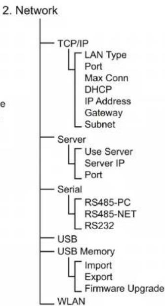
    A["2. Network"] --> B["TCP/IP"]
    B --> C["LAN Type"]
    B --> D["Port"]
    B --> E["Max Conn"]
    B --> F["DHCP"]
    B --> G["IP Address"]
    B --> H["Gateway"]
    B --> I["Subnet"]
    A --> J["Server"]
    J --> K["Use Server"]
    J --> L["Server IP"]
    J --> M["Port"]
    A --> N["Serial"]
    N --> O["RS485-PC"]
    N --> P["RS485-NET"]
    N --> Q["RS232"]
    A --> R["USB"]
    A --> S["USB Memory"]
    S --> T["Import"]
    S --> U["Export"]
    S --> V["Firmware Upgrade"]
    A --> W["WLAN"]
flowchart
graph TD
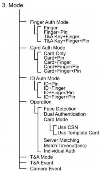
    A["3. Mode"] --> B["Finger Auth Mode"]
    A --> C["Card Auth Mode"]
    A --> D["ID Auth Mode"]
    A --> E["Operation"]
    B --> F["Finger\nFinger+Pin\nT&A Key+Finger\nT&A Key+Finger+Pin"]
    C --> G["Card Only\nCard+Pin\nCard+Finger\nCard+Finger/Pin\nCard+Finger+Pin"]
    D --> H["ID+Pin\nID+Finger\nID+Finger/Pin\nID+Finger+Pin"]
    E --> I["Face Detection\nDual Authentication\nCard Mode"]
    I --> J["Use CSN\nUse Template Card"]
    I --> K["Server Matching\nMatch Timeout(sec)\nIndividual Auth"]
    E --> L["T&A Mode"]
    E --> M["T&A Event"]
    E --> N["Camera Event"]
- Device
flowchart
graph TD
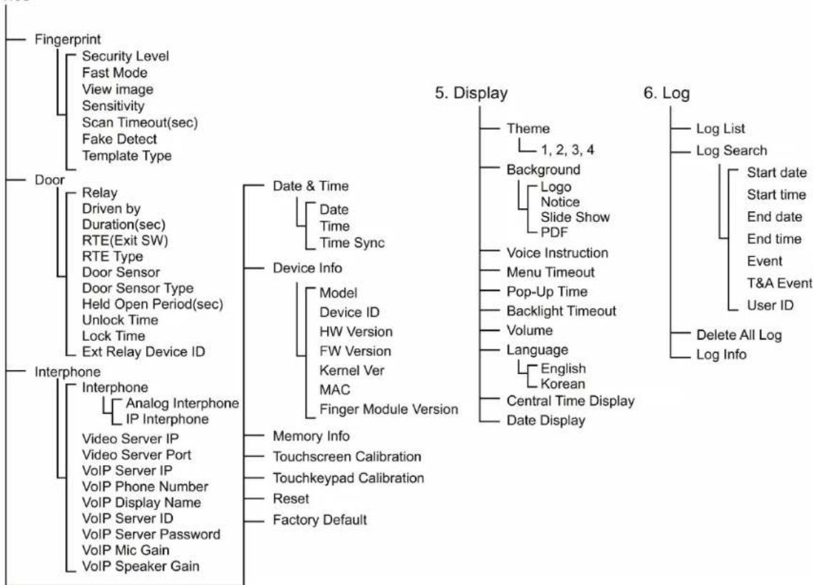
    A["Fingerprint"] --> B["Security Level"]
    B --> B1["Fast Mode"]
    B --> B2["View image"]
    B --> B3["Sensitivity"]
    B --> B4["Scan Timeout(sec)"]
    B --> B5["Fake Detect"]
    B --> B6["Template Type"]

    C["Door"] --> D["Relay"]
    D --> D1["Driven by"]
    D --> D2["Duration(sec)"]
    D --> D3["RTE(Exit SW)"]
    D --> D4["RTE Type"]
    D --> D5["Door Sensor"]
    D --> D6["Door Sensor Type"]
    D --> D7["Held Open Period(sec)"]
    D --> D8["Unlock Time"]
    D --> D9["Lock Time"]
    D --> D10["Ext Relay Device ID"]

    E["Interphone"] --> F["Interphone"]
    F --> F1["Analog Interphone"]
    F --> F2["IP Interphone"]
    F --> F3["Video Server IP"]
    F --> F4["Video Server Port"]
    F --> F5["VoIP Server IP"]
    F --> F6["VoIP Phone Number"]
    F --> F7["VoIP Display Name"]
    F --> F8["VoIP Server ID"]
    F --> F9["VoIP Server Password"]
    F --> F10["VoIP Mic Gain"]
    F --> F11["VoIP Speaker Gain"]

    G["Date & Time"] --> H["Date"]
    H --> H1["Time"]
    H --> H2["Time Sync"]

    I["Device Info"] --> J["Model"]
    I --> K["Device ID"]
    I --> L["HW Version"]
    I --> M["FW Version"]
    I --> N["Kernel Ver"]
    I --> O["MAC"]
    I --> P["Finger Module Version"]

    Q["5. Display"] --> R["Theme"]
    Q --> S["Background"]
    Q --> T["Voice Instruction"]
    Q --> U["Menu Timeout"]
    Q --> V["Pop-Up Time"]
    Q --> W["Backlight Timeout"]
    Q --> X["Volume"]
    Q --> Y["Language"]
    Q --> Z["English Korean"]
    Q --> AA["Central Time Display"]
    Q --> AB["Date Display"]

    AC["6. Log"] --> AD["Log List"]
    AC --> AE["Log Search"]

    AF["Memory Info"] --> AG["Touchscreen Calibration"]
    AF --> AH["Touchkeypad Calibration"]
    AF --> AI["Reset"]
    AF --> AJ["Factory Default"]
User Enrollment Process
flowchart
graph TD
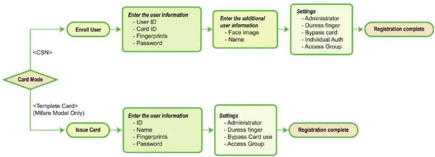
    A["Card Mode"] --> B["Enroll User"]
    A --> C["Issue Card"]
    B --> D["Enter the user information\n- User ID\n- Card ID\n- Fingerprints\n- Password"]
    D --> E["Enter the additional user information\n- Face image\n- Name"]
    E --> F["Settings\n- Administrator\n- Duress finger\n- Bypass card\n- Individual Auth\n- Access Group"]
    F --> G["Registration complete"]
    C --> H["Enter the user information\n- ID\n- Name\n- Fingerprints\n- Password"]
    H --> I["Settings\n- Administrator\n- Duress finger\n- Bypass Card use\n- Access Group"]
    I --> J["Registration complete"]
Registering User to Device
When a card reader recognizes a CSN card, it compares the unique identification number of the card to the unique identification number of the card registered to the device. The unique identification number is saved in the device when a user is registered to the device.
To use the CSN card, select [Mode] > [Operation] > [Card Mode] and select [Use CSN].
The EM model supports CSN card authentication mode only.
flowchart
graph LR
    A["User"] --> B["Enroll User"]
    B --> C["Edit User"]
    C --> D["Search"]
    D --> E["User Capacity Info"]
    E --> F["Delete All Users"]
    F --> G["User ID 12"]
    G --> H["Fingerprint None"]
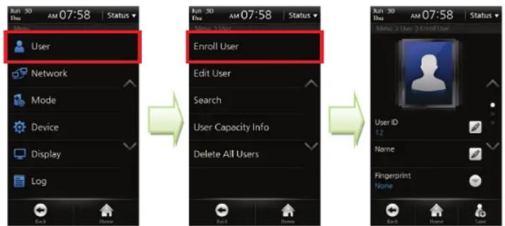
1 After entering into the Admin Menu, select [User] > [Enroll User].
2 Enter the user ID and at least one of card information, password, and fingerprints.
3 Press [Save] button to complete user registration.
User Info Items
| Face |
| User ID |
| Name |
| Fingerprint |
| Card |
| Password |
| Administrator |
| Duress Finger |
| Bypass Card |
| Individual Auth |
| Access Group |
Enroll User
Face
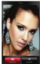
Touch the photo area and then the built-in camera is turned on. On the LCD screen, your face will be seen. Press [Capture] to save the face image. The registered face image on the device will appear on the LCD display upon authentication and it can be exported to BioStar software for valid identification check.
User ID
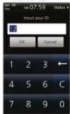
Enter the user ID and then press [OK]. The user ID can be specified within the range of 1\~4294967295. When you are entering into a new enrollment menu, a user ID is automatically given by the terminal.
Name
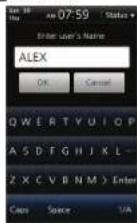
Enter the name and then press [OK]. You can use Korean characters, alphabets, numbers and special characters.
Fingerprint

text_image
Sun 30 PMI AM 08:00 Status User ID 12 Name AUX Fingerpoint Name Back Finish Help
text_image
Scan Finger Make the last finger Cancel
text_image
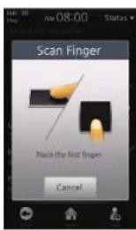
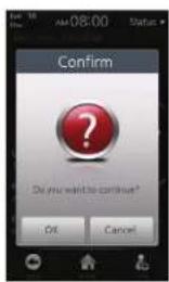
AM 08:00 Status Confirm Do you want to continue? OK CancelSelect [Fingerprint] and then the fingerprint registration procedure starts. You can register 1 \~ 10 fingers. One user can generally use two fingers. A fingerprint should be entered twice for confirmation. Enter one fingerprint and then press [OK] in the window prompting confirmation and enter the next fingerprint. Press [Cancel] to end the input. The number of entered fingerprints is displayed under the menu.
| Caution! | - Do not register an injured finger or one where the fingerprint is vague. - If the authentication success rate of a fingerprint is too low, delete the fingerprint and register a new fingerprint |
| Note | Please refer to[Chapter 1 > How to place a finger (p.15)]. |
Card
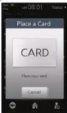
The device reads the card ID contained in the card and registers the ID. When the card input screen appears, place the card into the card reader.
Note
You must enter the user ID and at least one of card information/password/fingerprints to make a registration.
Password
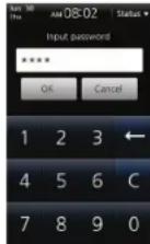
Enter the password and then press [OK]. A password should be entered twice for confirmation and composed of 4\~\~16-digits of numbers. If you enter numbers less than 4 digits, an alarm message will be displayed and the password will not be registered.
Administrator
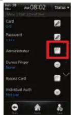
If this checkbox is checked, the user is registered as an administrator. If not, the user is registered as a general user.
■ Duress Finger
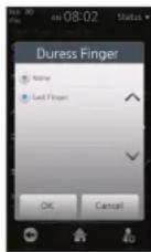
Duress Finger offers users a way of indication a duress situation, such as being forced to open a door. If the duress finger is presented, it allows access and simultaneously triggers the alarm or alert actions you specify. Duress finger can be set only when the user has entered two or more fingerprints in [fingerprint] menu. Select [Last finger] in the configuration window and then the last-entered fingerprint is used as a duress finger.
Caution!
- Do not use the duress fingerprint in your general entrance
- Register a fingerprint which can be used without causing any suspicion
Bypass Card
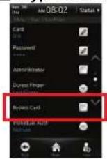
If required, select [Bypass Card]. Bypass card will allow the user to bypass regardless authentication mode of the device.
■ Individual Authentication Mode
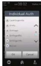
If required, set the individual authentication mode. If a user is set as [Individual Authentication Mode], the selected individual authentication mode for the user is prior to the authentication mode for the terminal. The individual authentication mode works for the corresponding authentication means only.
| Note | To use the individual authentication mode, select [Menu] > [Mode] > [Operation] and check [Individual Auth Mode]. |
■ Access Group
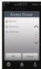
If required, set the access group. [Access Group] is set to whether the user can access it or not. You can select an access group from the access groups transferred from the BioStar software to the terminal.
Enroll
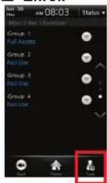
text_image
08:30 AM 08:03 Status Group 1 Full Accet Group 2 Not Use Group 3 Not Use Group 4 Not Use User User
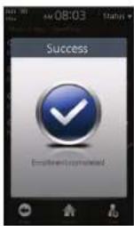
1 Press [Save] on the right-bottom side of the screen.
2 A window indicating user enrollment completion appears. The User registration has completed.
Edit/Delete User
Select [Menu] > [User] > [Edit User].

text_image
Enroll User Edit User Search User Capacity Info Delete All Users Status 1 2 3 4 5 6 Status Def you like Tensyung Edward C manabe team info Luna Park Status 1 2 3 4 5 6 Status User ID Frame Ringsprint Fama1 In the user list, select a desired user.
2 Edit the user information and then press [Add]. This procedure is identical with that of new user registration.
3 The success screen is displayed.
To delete a specific user, follow the procedure below.
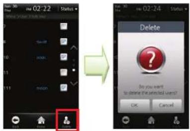
text_image
02:22 Status Delete Do you want to delete the selected User? OK Cancel1 In the user list, check the checkbox of the user to be deleted.
2 Click the [Delete] icon at the right bottom of the screen.
3 In the window prompting confirmation of deletion, press [OK].
Caution! If you have deleted user data that is not stored in the BioStar database, the user data cannot be restored.
Search User
Select [Menu] > [User] > [Search], select the search method, and then press [OK].
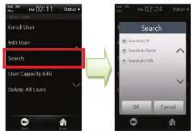
text_image
Enroll User Edit User Search User Capacity Info Delete All Users Search Search by ID Search by Name Search by CMS OK CancelSearch by ID
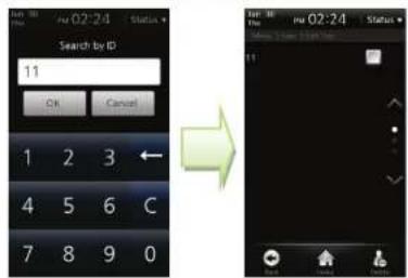
text_image
Search by ID 11 OK Cancel 1 2 3 ← 4 5 6 C 7 8 9 0 → Enter ID No: 02:24 Status 11An ID search window appears. Enter the ID and then press [OK]. The user whose ID matches to the entered ID is searched.
Search by Name
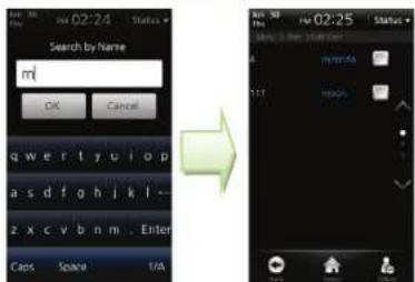
text_image
Search by Name mi OK Cancel qw w r t y u i o p a s d f g h i k l - z x c v b n m .. Enter Cacs Space 1/A www.mn 1:17 10:00 www.mn 1:17 10:00 www.mnA name search window appears. Enter the name and then press [OK]. It is not necessary to enter all characters of the name. When you enter some starting characters of the name, all users who have the name starting with the entered characters are searched.
Search by CSN
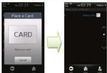
text_image
Place a Card CARD -Place your card CancelA card ID input window appears. Place the CSN card close to the card reader. The user who uses the card is searched.
- Checking the Registered User Info
text_image
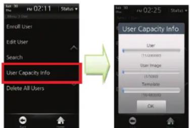
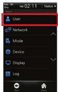
Enroll User Edit User Search User Capacity Info Delete All Users User (1520000) User Image (170000) Template (1840000) OK1 Select [Menu] > [User] > [User Capacity Info].
2 You can check the number of registered users/user images/templates and the remaining capacity.
Note
You can register up to 200,000 users (or 400,000 fingerprint templates) and 5,000 user face images on the device.
Deleting All Users
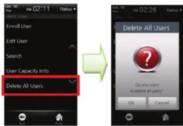
You can delete all users registered in the terminal.
text_image
Enroll User Edit User Search User Capacity Info Delete All Users Delete All Users Do you want to delete all users? OK Cancel1 Select [Menu] > [User] > [Delete All Users].
2 Press [OK] in the window confirming the deletion and then all user data registered in the terminal is deleted.
Caution!
If you have deleted user data that is not stored in the BioStar database, the user data cannot be restored.
Registering a User to a Card
Issuing a Card
When the terminal recognizes a template card, it reads the user information and template data from the card and requires users to place their fingerprint on the sensor for verification between live fingerprint and the fingerprint stored on the device.
The user information and fingerprints are not saved to the terminal but the template card only. Therefore, the user information must be separately managed.
To use the template card, select [Mode] > [Operation] > [Card Mode] and select [Use Template Card].
1 Select [Menu] > [User] > [Issue Card].
2 A registration window appears. Enter the user information.
3 Enter the User ID, Name, Fingerprint and Password.
4 Set the Administrator, Duress finger, Bypass card use and Access Group, if necessary.
5 Press [Issue] button at the right bottom and place the template card to the card reader to complete registration.
text_image
User Network Mode Device Display Log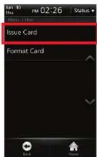
text_image
Issue Card Format Card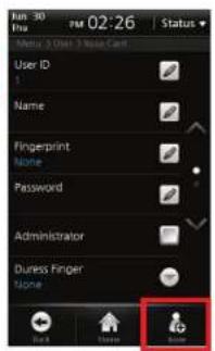
text_image
User ID Name Fingerprint None Password Administrator Duress Finger None Status: 30 Date: 2024-02-26 Status:| Note | - The user registered as |Bypass Card| will be authenticated as Bypass regardless of the authentication mode of the terminal. - [Access Group] is set to whether the user can access it or not. You can select an access group from the access groups transferred from the BioStar software to the terminal. |
| Caution! | You cannot use both the CSN Card and the Template Card simultaneously. |
■ Formatting a Card
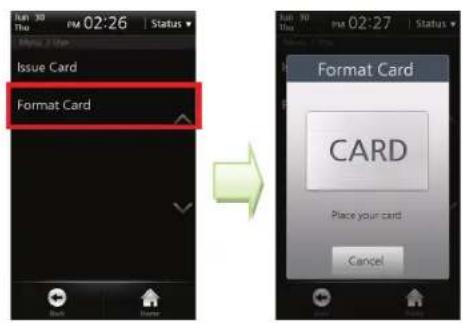
To use a card as a Template Card, all data saved in the card should be deleted.
text_image
Issue Card Format Card Format Card CARD Place your card Cancel1 Select [Menu] > [User] > [Format Card].
2 Place the Template Card to format to the card reader
3 A window confirming card format is displayed.
Network Setup
Set the network connection of BioStation T2. There are two network connections: direct connection that a BioStar client connects to a terminal and server connection that a terminal connects to the BioStar server.
TCP/IP Setup
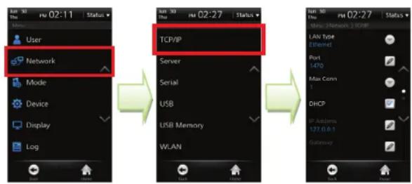
Set up TCP/IP for connecting the terminal and BioStar.
text_image
User Network Mode Device Display Log TCP/IP Server Serial USB USB Memory WLAN New Network 1 TCP/IP LAN Type Ethernet Port 1470 Max Conn 1 DHCP IP Antenna 127.0.0.1 Gateway1 Select [Menu] > [Network] > [TCP/IP].
2 LAN Type: Select the LAN type to be used for TCP/IP connection. (Values: Disabled/Ethernet/Wireless LAN)
3 Port: Assigns the TCP/IP port for the terminal. The default value is '1470'.
4 Max Conn: Sets the number of BioStar software that can be connected simultaneously. (Values: 1/4/8/16)
5 DHCP: Sets whether or not to use DHCP protocol.
6 IP Address: Enter the IP address when a fixed IP is used instead of DHCP protocol. If you don't know the IP address, please ask your network administrator.
7 Gateway: Enter the gateway address when a fixed IP is used instead of DHCP protocol. If you don't know the gateway address, please ask your network administrator.
8 Subnet: Enter the subnet mask address when a fixed IP is used instead of DHCP protocol. If you don't know the subnet mask address, please ask your network administrator.
Server Setup
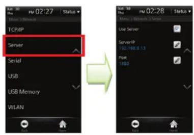
The terminal can communicate with the BioStar software server or the server application developed by using SDK. In the [Server], configure the IP address and ports of the server to connect to the terminal.
text_image
TCP/IP Server Serial USB USB Memory WLAN1 Select [Menu] > [Network] > [Server].
2 Use Server: Set up whether or not to use the server.
3 Server IP: Enter the server IP and then press [OK].
4 Port: Enter the port of the server and then press [OK].
5 After setting up all of the items mentioned above, press [Back] or [Home] to apply the settings to the terminal.
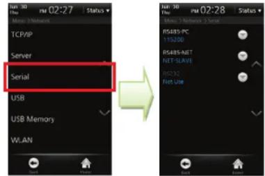
Serial Communication
Set the serial communication. The serial communication uses either of RS485 or RS232 and the connection type is classified to 'PC Connection' and 'SIO/Terminal Connection'.
text_image
Run 30 Run 02:27 Status Network TCP/IP Server Serial USB USB Memory WLAN Run 30 Run 02:28 Status Network 2 Normal 3 Server RSABS PC 115200 RSABS-NET HET-SAVE DOS 32 HET Use1 Select [Menu] > [User] > [Serial].
2 RS485-PC: Set whether or not to use RS485 communication between the terminal and a PC and the network speed between the terminal and a PC.
(Values: 115200/57600/38400/19200/9600/Not used)
3 RS485-NET: Set the RS485 communication with Secure I/O and other terminals. (Values: Not Used/Net-Slave/Net-Host)
- Net-Slave: Sets the terminal as Slave. - Net-Host: Sets the terminal as Host.
4 RS232: Set whether or not to use RS232 communication between the terminal and a PC and the network speed between the terminal and a PC.
Since RS232 and RS485-PC use a physically-identical port, you can use RS232 only when RS485 is set to Not Used. (Values: Not Used/9600/19200/38400/57600/115200)
| Note | RS485 communication between terminals can be configured with one Host terminal and slave terminals up to 7. In this case, up to 4 Secure I/Os can be connected. |

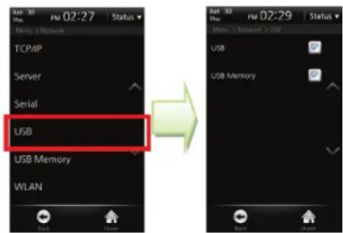
USB
text_image
TCP/IP Server Serial USB USB Memory WLAN1 Select [Menu] > [Network] > [USB].
2 USB: Check whether or not to permit USB connection to PC. (Mini USB)
3 USB Memory: Check whether or not to permit USB memory connection. (USB A Type)
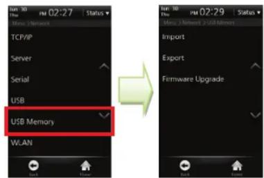
USB Memory
text_image
Jun 10 Date 02:27 Status Menu Network TCP/IP Server Serial USB USB Memory WLAN Import Export Firmware Upgrade1 Select [Menu] > [Network] > [USB Memory].
2 Import: In the window, select a terminal ID of which data will be imported and click [OK].
3 Export: After touching [Export], wait until the export is completed.
4 Firmware Upgrade: Select the version to upgrade and then press [OK].
5 After completing import and firmware upgrade, the terminal is rebooted.
Note
To use a USB memory, select [Menu] > [Network] > [USB] and check USB memory item and then you can enter into the [USB Memory] menu.
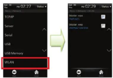
Wireless LAN
You can select one of 4 wireless LAN settings (Preset) saved in advance through the BioStar software.
To set the Preset, enter the SSID, encryption type, and encryption key through the BioStar software.
text_image
TCP/IP Server Serial USB USB Memory WLAN u30 02:27 Status u30 02:29 Status Main: 1 Network 1 W/WR Dictar wpe WEP4/AES Dictar wpe WEP4/128/2561 Select [Menu] > [Network] > [WLAN].
2 Select the Preset to be used for wireless LAN connection.
Authentication Mode
You can authenticate users in the operation mode set for the specified time schedule. One time schedule used for setting the authentication mode can be selected among the time schedules set through the BioStar software. The maximum number of time schedules is 128.
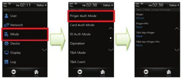
Finger Auth Mode
text_image
User Network Mode Device Display Log Finger Auth Mode Card Auth Mode ID Auth Mode Operation T&A Mode T&A Event Status: 02:11 Status Status: 02:30 Status Status: 02:30 Status Status: 02:30 Status Status: 02:30 Status Status: 02:30 Status Status: 02:30 Status Status: 02:30 Status Status: 02:30 Status Status: 02:30 Status Status: 02:30 Status Status: 02:31 Status Status: 02:31 Status Status: 02:31 Status Status: 02:31 Status Status: 02:31 Status Status: 02:31 Status Status: 02:31 Status Status: 02:31 Status Status: 02:31 Status Status: 02:31 Status Status: 02:32 Status Status: 02:32 Status Status: 02:32 Status Status: 02:32 Status Status: 02:32 Status Status: 02:32 Status Status: 02:32 Status Status: 02:32 Status Status: 02:32 Status Status: 02:32 Status Status: 02:33 Status Status: 02:33 Status Status: 02:33 Status Status: 02:33 Status Status: 02:33 Status Status: 02:33 Status Status: 02:33 Status Status: 02:33 Status Status: 02:33 Status Status: 02:33 Status Status: 02:34 Status Status: 02:34 Status Status: 02:34 Status Status: 02:34 Status Status: 02:34 Status Status: 02:34 Status Status: 02:34 Status Status: 02:34 Status Status: 02:34 Status Status: 02:34 Status Status: 02:35 Status Status: 02:35 Status Status: 02:35 Status Status: 02:35 Status Status: 02:35 Status Status: 02:35 Status Status: 02:35 Status Status: 02:35 Status Status: 02:35 Status Status: 02:36 Status Status: 02:36 Status Status: 02:36 Status Status: 02:36 Status Status: 02:36 Status Status: 02:36 Status Status: 02:37 Status Status: 02:37 Status Status: 02:37 Status Status: 02:37 Status Status: 02:37 Status1 Select [Menu] > [Mode] > [Finger Auth Mode].
2 Finger: Authenticated by fingerprint only.
3 Finger + Pin: Authenticated by entering the fingerprint and then the password.
4 T&A Key + Finger: Authenticated by pressing the corresponding T&A event key and entering the fingerprint.
5 T&A Key + Finger + Pin: Authenticated by pressing the corresponding T&A event key and entering the fingerprint and password.
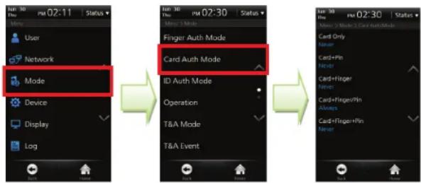
Card Auth Mode
flowchart
graph LR
    A["User"] --> B["Network"]
    B --> C["Mode"]
    C --> D["Device"]
    D --> E["Display"]
    E --> F["Log"]

    G["Finger Auth Mode"] --> H["Card Auth Mode"]
    H --> I["ID Auth Mode"]
    I --> J["Operation"]
    J --> K["T&A Mode"]
    K --> L["T&A Event"]

    M["Card Only Never"] --> N["Card+Pin Never"]
    N --> O["Card+Finger Never"]
    O --> P["Card+Finger+Pin Always"]
    P --> Q["Card+Finger+Pin Never"]
1 Select [Menu] > [Mode] > [Card Auth Mode].
2 Card Only: Authenticated by card only. In this mode, the card type to be used for authentication must be specified on [Mode > Card Mode].
3 Card + Pin: Authenticated by placing the card into the reader and entering the password.
4 Card + Finger: Authenticated by placing the card into the reader and entering the fingerprint.
5 Card + Finger/Pin: Authenticated by placing the card into the reader and entering the password or a fingerprint.
6 Card + Finger + Pin: Authenticated by placing the card into the reader and entering a fingerprint and the password.
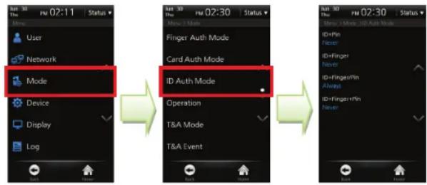
ID Auth Mode
text_image
User Network Mode Device Display Log Run 02:11 Status Run 02:30 Status New / Make Finger Auth Mode Card Auth Mode ID Auth Mode Operation T&A Mode T&A Event Run 02:30 Status New / Make, Job Auth Mode ID+Pin Finger ID+Finger Never ID-Finger+Pin Award ID-Finger+Pin Never1 Select [Menu] > [Mode] > [ID Auth Mode].
2 ID + Pin: Authenticated by entering the ID and then the password.
3 ID + Finger: Authenticated by entering the ID and then the fingerprint.
4 ID + Finger/Pin: Authenticated by entering the ID and then entering the password or a fingerprint.
5 ID + Finger + Pin: Authenticated by entering the ID, the fingerprint and then the password.
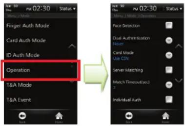
Operation
text_image
Finger Auth Mode Card Auth Mode ID Auth Mode Operation T&A Mode T&A Event1 Select [Menu] > [Mode] > [Operation].
2 Face Detection: Set to use Face Detection or not. When face detection is checked, authentication is successfully made only when face detection is succeeded after card or password authentication.
3 Dual Authentication: Set the Dual authentication mode. Dual Authentication needs consecutive authentications from two different users for high security. If the second authentication is not made within 15 seconds from the first authentication, the first authentication will become invalid and you have to do dual authentication again.
4 Card Mode: Set the card type used on the terminal. (Values: Not Used/Use CSN/Use Template Card) The EM model supports CSN card authentication mode only.
CSN: A terminal reads the unique Card Serial Number (CSN) given to a card and then saves the number. When a card is placed close to the card sensor by the terminal, the terminal then reads the CSN and compares the CSN to the CSN saved in the terminal for identification purposes.
- Template Card: User information including user ID and other identification information is saved in the card. When a card is placed close to the card sensor by the terminal, the terminal then reads the user information from the card for identification purposes.
5 Server Matching: Set to use Server Matching or not. If Server Matching is selected, authentication is based on the user data saved in the server, instead of in the terminal. If connection to the server is disconnected, authentication is based on the user data saved in the terminal without making any additional changes to the configuration. Server matching works only with BioStar SE (Standard Edition). Please refer to BioStar user guide for detail.
6 Match Timeout (5/10/15/20/25/30): Sets up the waiting time for Server Matching and Face Detection. In case there is no answer from the server during Matching Time or the face cannot be detected, the authentication will fail.
7 Individual Auth: Sets whether or not to use the Individual Authentication mode. You can set authentication mode by individual user. Individual authentication mode for the user is prior to the authentication mode for the terminal.
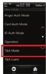
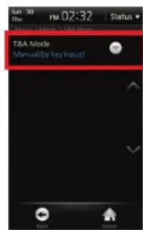
T&A Mode
Set up the T&A mode to apply to the terminal.
text_image
TBA Mode T&A Event
text_image
T&A Mode (Manual) by key input)
text_image
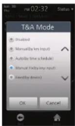
T&A Mode Disabled Manual (bytes input) Auto (by time schedule) Manual (bytes input) Fixed (by device) OK Cancel1 Select [Menu] > [Mode] > [T&A Mode].
2 Press [T&A Mode] to set the mode. (Disabled/Manual/Auto/Manual Fix/Fixed)
Note
For more details on the T&A mode, see [Chapter 3. User Menu >2. T&A Mode > T&A Mode Setup (p.46)].
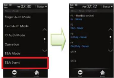
T&A Event
BioStar software allows you to check automatic time and activation of T&A events with F1\~F4 or the additional T&A events (EXT 01\~12). T&A events can be set up through BioStar only. On the terminal, the events can only be checked.
text_image
T&A Event Finger Auth Mode Card Auth Mode ID Auth Mode Operation T&A Mode T&A Mode 3 Mode 3 T&A Event F1 - Fidelity device) In - Never F2 Out - Never F3 In Duty - Never F4 Out Duty - Never EXT1 EXT21 Select [Menu] > [Mode] > [T&A Event].
2 You can check the settings through the BioStar software.
Camera Event
When a camera event occurs, the camera will start recording when the event begins and then save the still image log. Camera events can be set up through BioStar only. On the terminal, the events can only be checked.
1 Select [Menu] > [Mode] > [Camera Event].
2 You can check the settings through the BioStar software.
Device Setup
Fingerprint Setting
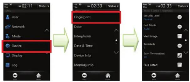
Select [Menu] > [Device] > [Fingerprint].
flowchart
graph LR
    A["User"] --> B["Device"]
    C["Network"] --> B
    D["Mode"] --> B
    E["Display"] --> B
    F["Log"] --> B
    B --> G["Fingerprint"]
    G --> H["Door"]
    H --> I["Interphone"]
    I --> J["Date & Time"]
    J --> K["Device Info"]
    K --> L["Memory Info"]
    L --> M["Back"]
    M --> N["Finish"]
    N --> O["Scan Timeout(Dec) 10"]
    O --> P["Fake Detect"]
1 Security Level (Normal/Secure/Most Secure): The security level is determined by False Acceptance Ratio (FAR). FAR stands for a ratio of accepting unregistered fingerprints. The lower the FAR is, the higher the security is, however, FRR (False Reject Rate) gets higher so that the recognition ratio of the registered users gets lower. For the general T&A management purposes, we recommend the Normal. However, if you need high access control and security, we recommend you to raise the security level from Moderate to Secure or Most Secure.
2 Fast Mode (Normal/Fast/Fastest/Auto): If 1:N Recognition Mode is used while hundreds of users are saved in the terminal, the recognition time may be too long. In this case, you can reduce the recognition time by setting the speed of 1:N recognition. At this time, FRR may be higher than before. [Auto] automatically determines the recognition speed according to the number of total fingerprint templates registered to the terminal.
3 View Image: Check whether or not to display the fingerprint image on the screen. With this function, users can check the registered fingerprint image on the LCD screen and input the right fingerprint.
4 Sensitivity (0\~7): Set the sensitivity of the fingerprint scanner. At the high sensitivity, it is easier to enter fingerprints. However, at the low sensitivity, the quality of entered fingerprint images can be always high. For the general use, we recommend you to set the value to Max. If the terminal can be affected by direct sunlight, relieve the effect by lowering this value.
5 Scan Timeout(sec) (1\~20): Set the fingerprint input time and then press [OK]. Authentication fails when the user does not enter the fingerprint within the specified time.
6 Fake Detect: Check whether or not to run an examination to detect the fake fingerprint attack.
7 Template Type (Suprema/ISO 19794-2/ANSI 378): Set the template type and then press [OK].
Note Generally, the default values are recommended.
Door
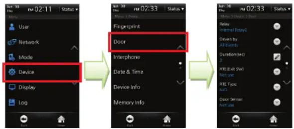
Select [Menu] > [Device] > [Door].
text_image
User Network Mode Device Display Log Fingerprint Door Interphone Date & Time Device Info Memory Info Fingerprint Interphone Date & Time Memory Info Fingerprint Door Interphone Date & Time Memory Info Fingerprint Door Interphone Date & Time Memory Info Fingerprint Door Interphone Date & Time Memory Info Fingerprint Door Interphone Date & Time Memory Info Fingerprint Door Interphone Date & Time Memory Info Fingerprint Door Interphone Date & Time Memory Info1 Relay: Select a relay to open the door on authentication. (Values: Not Used/ Internal Relay 0/ Internal Relay 1/ External Relay 0/ External Relay 1/ SIO0 Relay 0/ SIO0 Relay 1/ SIO1 Relay 0/ SIO1 Relay 1/ SIO2 Relay 0/ SIO2 Relay 1/ SIO3 Relay 0/ SIO3 Relay 1)
2 Driven by: Set the event that triggers door opening and then press [OK].
- All Events: The door is open regardless of the authentication event type.
- Authentication : The door is open only for the general authentication events, not for the T&A events.
– T&A Event: The door is open for the T&A events where the relay will be used. - Authentication + T&A Event: The door is open for the T&A events where the relay will be used among the general authentication and T&A authentication.
- Disabled: The door is not open for all events including all general authentication events and all T&A events.
3 Duration (sec): Sets up the time for which the relay keeps the door open after an event. The relay will close the door again after the time has elapsed.
4 RTE(Exit SW): Select the relay for the door switch and then press [OK]. (Values: Input 0/ Input 1/ Input 2/ Input 3/ SIO0 Input 0/ SIO0 Input 1/ SIO0 Input 2/ SIO0 Input 3/ SIO1 Input 0/ SIO1 Input 1/ SIO1 Input 2/ SIO1 Input 3/ SIO2 Input 0/ SIO2 Input 1/ SIO2 Input 2/ SIO2 Input 3/ SIO3 Input 0/ SIO3 Input 1/ SIO3 Input 2/ SIO3 Input 3)
5 RTE Type: Select the door switch operation type and then press [OK]. (Values: N/O, N/C)
6 Door Sensor: Select the detection mechanism for door opening and then press [OK]. (Values: Input 0/ Input 1/ Input 2/ Input 3/ SIO0 Input 0/ SIO0 Input 1/ SIO0 Input 2/ SIO0 Input 3/ SIO1 Input 0/ SIO1 Input 1/ SIO1 Input 2/ SIO1 Input 3/ SIO2 Input 0/ SIO2 Input 1/ SIO2 Input 2/ SIO2 Input 3/ SIO3 Input 0/ SIO3 Input 1/ SIO3 Input 2/ SIO3 Input 3)
7 Door Sensor Type: Select the door sensor operation type and then press [OK]. (Values: N/O, N/C)
8 Held Open Period(sec): Set the duration of time for the alarm to go off after the door opens and then press [OK].
9 Unlock Time: Set the time to keep the door forcibly unlocked. During the unlock time, the door is not closed. (Values: Not Used/Always/Auto IN/Auto Out). The unlock time can be set through the BioStar only.
10 Lock Time: Set the time to keep the door forcibly locked and then press [OK]. (Not Used/ Always/ Auto IN/ Auto Out)
Note
Generally, the default values are recommended.
Interphone Setting
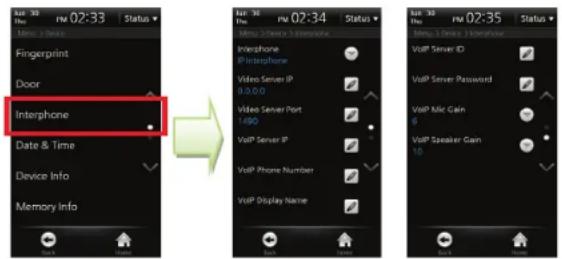
Select [Menu] > [Device] > [Interphone].
text_image
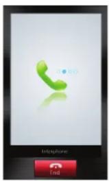
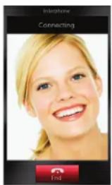
Fingerprint Door Interphone Date & Time Device Info Memory Info Up To 30 Thu 02:33 Status ▼ Menu 1 Store > Interface Interphone IPtterphone Video Server IP 0.0.0.0 Video Server Port 1490 VoIP Server IP VoIP Phone Number VoIP Display Name Up To 30 Thu 02:34 Status ▼ Menu 1 Store > Interface Interphone IPtterphone Video Server IP 0.0.0.0 Video Server Port 1490 VoIP Server IP VoIP Phone Number VoIP Display Name Up To 30 Thu 02:35 Status ▼ Menu 1 Store > Interface VoIP Server ID VoIP Server Password VoIP Mic Gain 6 VoIP Speaker Gam 10After setting the interphone, you can make a call by pressing the Call key on the BioStation T2 terminal. The following screens show screens per interphone type.
text_image
OK Telephone EndAnalog Interphone
text_image
Telephone Connecting 1:42IP Interphone
1 Interphone: Select an interphone to use and then press [OK]. (Not use/Analog Interphone/IP Interphone)
2 Video Server IP: If you have selected IP Interphone, enter the video server IP. If you don't know server IP, please ask your network administrator.
3 Video Server Port: Enter the video server port. If you don't know server Port, please ask your network administrator.
4 VoIP Server IP: If you have selected IP Interphone, enter the VoIP server IP.
5 VoIP Phone Number: If you have selected IP Interphone, enter the VoIP phone number.
6 VoIP Display Name: If you have selected IP Interphone, enter the VoIP name.
7 VoIP Server ID: Enter the VoIP server ID. You can use alphabets, numbers and special characters.
8 VoIP Server Password: Enter the VoIP server password and then press [OK].
9 VoIP Mic Gain: Adjust the volume of the VoIP microphone (0\~10).
10 VoIP Speaker Gain: Adjust the volume of the VoIP speaker (0\~10).
| Note | The only following videophone models are compatible with BioStation T2. |
| - COMMAX / CAV-35N | |
| - COMMAX / CAV-50H | |
| - COMMAX / CAV-50P |
Date & Time Setup
Set up the time displayed on the terminal. Set up the accurate time to receive accurate log data.
Select [Menu] > [Device] > [Date & Time].
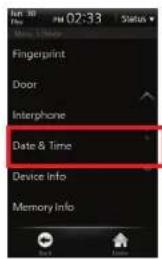
text_image
Fingerprint Door Interphone Date & Time Device Info Memory Info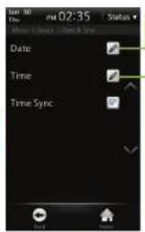
text_image
Date Time Time Sync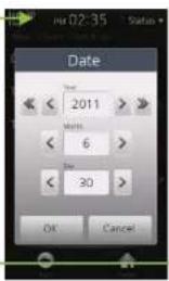
text_image
Date Time 2011 Minutes 6 Day 30 OK Cancel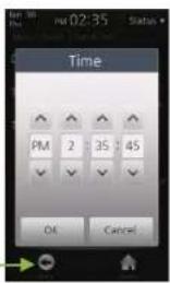
text_image
Time PM 2 35:45 OK Cancel1 Date (YYYY/MM/DD): Enter the current date by using [<] and [>] and then press [OK].
2 Time (PM//hh/mm/ss): Enter the current time by using [ʌ] and [v] and then press [OK].
3 Time Sync: You can use Time Sync in the server mode. The terminal's time will be synchronized with the server time. The time will be synchronized once every hour and only if the time difference between terminal and server is more than 5 seconds.
Device Info
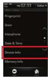
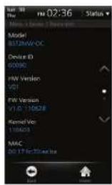
You can check the model name, device ID, H/W version, F/W version, kernel version, MAC and fingerprint module version. Select [Menu] > [Device] > [Device Info].
text_image
Fingerprint Door Interphone Date & Time Device Info Memory Info
text_image
Model BI72M/W-OC Device ID 60090 PW Version V01 PW Version V1.0 - 10528 Kernel Ver 110623 MAC 02.17 PC/34/2023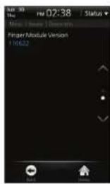
text_image
02:38 Status Music / Free | Demistry Finger/Module Version 1.0622Memory Info
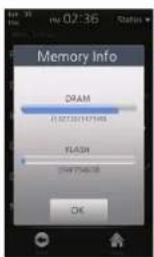
Check the memory usage status. Select [Menu] > [Device] > [Memory Info].
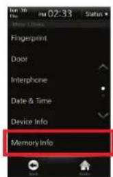
text_image
Fingerprint Door Interphone Date & Time Device Info Memory Info
text_image
Memory Info DRAM 0:00:00(167)KB FLASH 2497548.78 OKTouchscreen Calibration
Select [Menu] > [Device] > [Touchscreen Calibration].
1 Press the cross mark on the screen. When the cross mark moves, follow it by touching with your finger on the screen.
2 After calibration is finished, the cross mark will soon disappear
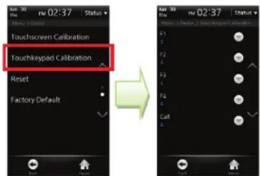
Touchkeypad Calibration
Adjusts the sensitivity of the bottom touch keys. As the setting value is smaller, the sensitivity is high. As the setting value is larger, the sensitivity is low.
text_image
Touchscreen Calibration Touchkeypad Calibration Reset Factory Default F1 F2 F3 F4 Call1 Select [Menu] > [Device] > [Touchkeypad Calibration].
2 Set sensitivity of each of F1\~F4 keys and the Call key. (Value: 0\~9)
Note
Generally, the default value is recommended. The factory default value is [4].
Reset
Reboots the BioStation T2 terminal.
1 Select [Menu] > [Device] > [Reset].
2 Press [OK] to reset the terminal.
Factory Default
Initializes the BioStation T2 to the factory default.
1 Select [Menu] > [Device] > [Factory Default].
2 Press [OK] to reset all settings to the factory default value.
| Caution! | Please be aware that the factory default means that all wallpapers, sound effects, notices, etc. that you have downloaded from BioStar will be deleted. However, even if you execute factory default, the registered user data and log data will not be deleted. |
Display Setup
Select [Menu] > [Display].
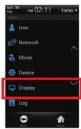
text_image
User Network Mode Device Display Log

text_image
File 30 Time FM 02:38 Status Theme Theme 1 Background Logo Voice Instruction Menu Timeout 10 sec Pop-Up Time 7 sec Backlight Timeout 10 sec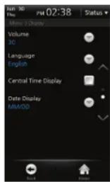
text_image
Run 30 Time PM 02:38 Status Menu > Display Volume 30 Language English Central Time Display Date Display MM/DD Back FinishNote
If [Notice] and [Slide Show] are selected, the logo screen will be displayed for authentication or other operations and one of the notice screen, the slide show screen, and PDF screen will appear when the menu timeout has passed (after 30 seconds if the menu timeout has been set to Unlimited). When you touch the screen in the [Notice] or [Slide Show] status, the LCD backlight will be turned on if it is turned off. If the LCD backlight is already turned on, the screen will be switched to the logo screen.
1 Theme: Select a theme for the screen background and then press [OK]. (Values: Theme 1/Theme 2/Theme 3/Theme 4)
2 Background: Select a background for the Standby screen and then press [OK]. (Values: Logo/Notice/Slide Show/PDF]
3 Voice Instruction: Select whether or not to use the voice announcement. You can change pre-defined voice announcement by an event through BioStar Software.
4 Menu Timeout: If no key is pressed during the selected timeframe, the display returns to main screen (Values: Infinite/10 sec/20 sec/30 sec)
5 Pop-Up Time: Select how long the message will be displayed on the screen during authentication (Values: 0.5 sec/1 sec/2 sec/3 sec/4 sec/5 sec)
6 Backlight Timeout: If no key is pressed during the allotted timeframe, the LCD backlight will be turned off (Values: Unlimited/10 sec/20 sec/30 sec/40 sec/50 sec/60 sec)
7 Volume (0\~100%): Select volume of the sound effects. 0% means that no sound will be emitted.
8 Language: Select the language displayed on the terminal and then press [OK]. You have to reboot the terminal to activate language changes.
9 Central Time Display: Select whether or not the time and date will be displayed on the center of standby screen.
10 Date Display (MM/DD,DD/MM): Select the date display format on the terminal and then press [OK]
Log
Log List
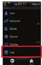
text_image
User Network Mode Device Display Log
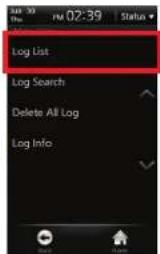
text_image
Log List Log Search Delete All Log Log Info
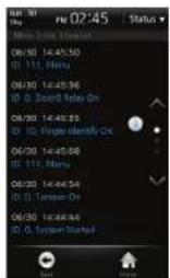
text_image
02:45 Status 06/30 14:45:30 ID: 111, Menu 06/30 14:45:36 ID: 0, Board9, Relay On 06/30 14:45:33 ID: 0, Trigger Identify Out 06/30 14:45:38 ID: 111, Menu 06/30 14:44:34 ID: 0, Tension On 06/30 14:48:44 ID: 0, System Started1 Select [Menu] > [Log] > [Log List], then the list of logs will be displayed.
2 Select a desired log to view the details.
3 The still image log is marked

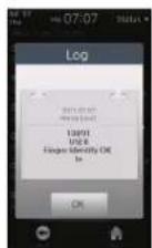
Event Log
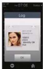
Still Image Log
Log Search
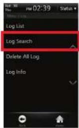
text_image
Log List Log Search Delete All Log Log Info
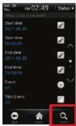
text_image
For: 36 Thu: PM 02:49 Status How Like My Search Start date 2011 06:30 Start time 00:00:00 End date 2011 06:30 End time 22:00:00 Event: AF TSA Event AS Search
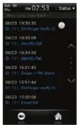
text_image
Hot 30 Time 02:53 Status * How Time Log Touch 06/23 19:35:35 D 111 Chifinger Verify D 06/23 19:35:09 D 111 Chifinger Fail 06/23 19:34:50 D 111 Chifinger Fail 06/23 16:21:45 D 111 Phone + (No Batch) 06/23 15:51:44 D 111 Chifinger verify D 06/23 15:50:08 D 111 Email Call Exit Finish1 Select [Menu] > [Log] > [Log Search].
2 Select a desired item among Start Date, Start Time, End Date, End Time, Event, T&A Event, and User ID and then press [Search].
3 The result of searching logs is displayed.
BioStation T2 User Guide
4 Admin Menu
Delete All Log
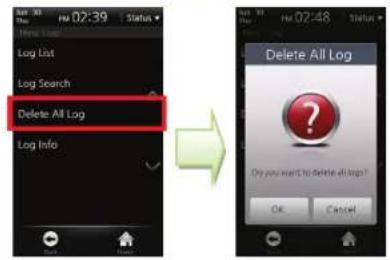
text_image
Log List Log Search Delete All Log Log Info Delete All Log Do you want to Delete all logs? OK Cancel1 Select [Menu] > [Log] > [Delete All Log].
2 Press [OK] to delete all saved logs.
Log Info
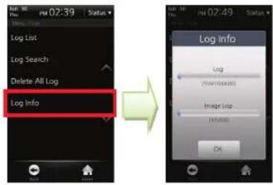
text_image
Log Info Log List Log Search Delete All Log Log info Log LOG Info LOG LOG Info LOG LOG Info LOG LOG Info LOG LOG Info LOG LOG Info LOG LOG Info LOG LOG Info LOG LOG Info LOG LOG Info LOG LOG Info LOG LOG Info LOG LOG Info LOG LOG Info LOG LOG Info LOG LOG Info LOG LOG Info LOG LOG Info LOG LOG Info LOG LOG Info LOG LOG Info Log LOG Info LOG LOG Info LOG LOG Info LOG LOG Info LOG LOG Info LOG LOG Info LOG LOG Info LOG LOG Info LOG LOG Info LOG LOG Info LOG LOG Info LOG LOG Info LOG LOG Info LOG LOG Info LOG LOG Info LOG LOG Info LOG LOG Info LOG LOG Info LOG LOG Info LOG LOGInfo1 Select [Menu] > [Log] > [Log Info].
2 Check the number of logs saved in the terminal and the remaining available capacity.
Note
You can save up to 1,000,000 event logs and up to 5,000 still image logs.
5 Appendix
Product Specifications
| Item | Specifications | |
| Card Options | 125KHz EM, 13.56MHz ISO14443 A/B (MIFARE) | |
| Capacity | Maximum Number of Users | 200,000 |
| Template Capacity | 400,000(1:1), 20,000(1:N) | |
| Log Capacity | Event Logs: 1,000,000 / Image Logs: 5,000 | |
| Interface | Communication Interface | Ethernet, WLAN, RS485 x 1ch,RS232/RS485(changeable) x 1ch, USB |
| Wiegand | IN&OUT (Switchable) | |
| TTL I/O | 4 inputs | |
| Built-in Relay | 2 | |
| PoE | Yes | |
| Hardware | CPU | 667Mhz RISC x 1, 533MHz DSP x 1 |
| Memory | 1GB flash, 256MB RAM | |
| LCD Display | 5.0 inch WVGA touchscreen | |
| Fingerprint Sensor | Optical | |
| Camera | Face detection & videophone | |
| Audio | 16 bit Hi-Fi voice & sound indication | |
| Operating Temperature | -20°C ~ 50°C | |
| Humidity | 90% | |
| Tamper | Switch | |
| Input Voltage | 12V DC | |
| Dimensions | 155 mm(W) x 155 mm(H) x 40 mm(D) | |
Electrical Specification
| Min. Value | Mean Value | Max. Value | Remark | |
| Power | ||||
| Voltage (V) | 10.8 | 12 | 13.2 | Use the power adapter which meets the specifications. |
| Current Consumption (mA) - | 570 | |||
| Current Consumption with USB Wireless LAN (mA) | - - 1070 | |||
| Switch Input | ||||
| VIH(V) 3.5 - 10.0 | ||||
| VIL(V) - - 2.0 | ||||
| Pull-up Resistance (Ω) | - | 4.7K | - | The input ports are pulled up with 4.7 KΩ resistors. |
| Wiegand Output | ||||
| VOH(V) | - | 5 | - | |
| VOL(V) | - 0.8 - | |||
| Pull-up Resistance (Ω) | - | 4.7K | - | |
| Relay | ||||
| Voltage | - | - | 24 VDC | |
| Current | - | 0.5 A | 1.0 A | |
FCC Rules
Caution
Changes or modifications not expressly approved by the manufacturer responsible for compliance could void the user's authority to operate the equipment.
Warning
This device complies with part 15 of the FCC Rules. Operation is subject to the following two conditions: (1) This device may not cause harmful interface, and (2) this device must accept any interface received, including interference that may cause undesired operation.
Information to User
This equipment has been tested and found to comply with the limit of a Class B digital device, pursuant to Part 15 of the FCC Rules. These limits are designed to provide reasonable protection against harmful interference in a residential installation.
This equipment generates, user and can radiate radio frequency energy and, if not installed and used in accordance with the instructions, may cause harmful interference to radio communications.
However, there is no guarantee that interference will not occur in a particular installation; if this equipment does cause harmful interference to radio or television reception, which can be determined by turning the equipment off and on, the user is encouraged to try to correct the interference by one or more the following measures:
- Reorient / Relocate the receiving antenna.
- Increase the separation between the equipment and receiver.
- Connect the equipment into an outlet on a circuit difference from that to which the receiver is connected.
- Consult the dealer or an experienced radio/TV technician for help
Font License
Copyright (c) 2010, NHN Corporation (http://www.nhncorp.com), with Reserved Font Name Nanum, Naver Nanum, NanumGothic, Naver NanumGothic, NanumMyeongjo, Naver NanumMyeongjo.
This Font Software is licensed under the SIL Open Font License, Version 1.1.
This license is copied below, and is also available with a FAQ at: http://scripts.sil.org/OFL
SIL OPEN FONT LICENSE
Version 1.1 - 26 February 2007
PREAMBLE
The goals of the Open Font License (OFL) are to stimulate worldwide development of collaborative font projects, to support the font creation efforts of academic and linguistic communities, and to provide a free and open framework in which fonts may be shared and improved in partnership with others.
The OFL allows the licensed fonts to be used, studied, modified and redistributed freely as long as they are not sold by themselves.
The fonts, including any derivative works, can be bundled, embedded, redistributed and/or sold with any software provided that any reserved names are not used by derivative works.
The fonts and derivatives, however, cannot be released under any other type of license.
The requirement for fonts to remain under this license does not apply to any document created using the fonts or their derivatives.
DEFINITIONS
"Font Software" refers to the set of files released by the Copyright Holder(s) under this license and clearly marked as such. This may include source files, build scripts and documentation.
"Reserved Font Name" refers to any names specified as such after the copyright statement(s).
"Original Version" refers to the collection of Font Software components as distributed by the Copyright Holder(s).
"Modified Version" refers to any derivative made by adding to, deleting, or substituting? in part or in whole? any of the components of the Original Version, by changing formats or by porting the Font Software to a new environment.
"Author" refers to any designer, engineer, programmer, technical writer or other person who contributed to the Font Software.
PERMISSION & CONDITIONS
Permission is hereby granted, free of charge, to any person obtaining a copy of the Font Software, to use, study, copy, merge, embed, modify, redistribute, and sell modified and unmodified copies of the Font Software, subject to the following conditions:
1) Neither the Font Software nor any of its individual components, in Original or Modified Versions, may be sold by itself.
2) Original or Modified Versions of the Font Software may be bundled, redistributed and/or sold with any software, provided that each copy contains the above copyright notice and this license. These can be included either as stand-alone text files, human-readable headers or in the appropriate machine-readable metadata fields within text or binary files as long as those fields can be easily viewed by the user.
3) No Modified Version of the Font Software may use the Reserved Font Name(s) unless explicit written permission is granted by the corresponding Copyright Holder. This restriction only applies to the primary font name as presented to the users.
4) The name(s) of the Copyright Holder(s) or the Author(s) of the Font Software shall not be used to promote, endorse or advertise any Modified Version, except to acknowledge the contribution(s) of the Copyright Holder(s) and the Author(s) or with their explicit written permission.
5) The Font Software, modified or unmodified, in part or in whole, must be distributed entirely under this license, and must not be distributed under any other license. The requirement for fonts to remain under this license does not apply to any document created using the Font Software.
TERMINATION
This license becomes null and void if any of the above conditions are not met.
DISCLAIMER
THE FONT SOFTWARE IS PROVIDED "AS IS", WITHOUT WARRANTY OF ANY KIND, EXPRESS OR IMPLIED, INCLUDING BUT NOT LIMITED TO ANY WARRANTIES OF MERCHANTABILITY, FITNESS FOR A PARTICULAR PURPOSE AND NONINFRINGEMENT OF COPYRIGHT, PATENT, TRADEMARK, OR OTHER RIGHT.
IN NO EVENT SHALL THE COPYRIGHT HOLDER BE LIABLE FOR ANY CLAIM, DAMAGES OR OTHER LIABILITY, INCLUDING ANY GENERAL, SPECIAL, INDIRECT, INCIDENTAL, OR CONSEQUENTIAL DAMAGES, WHETHER IN AN ACTION OF CONTRACT, TORT OR OTHERWISE, ARISING FROM, OUT OF THE USE OR INABILITY TO USE THE FONT SOFTWARE OR FROM OTHER DEALINGS IN THE FONT SOFTWARE.

natural_image
Abstract graphic with red flowing bands and a world map background (no text or symbols)Suprema Inc.
16F Parkview Office Tower, Jeongja-dong, Bundang-gu Seongnam, Gyeonggi, Korea 463-863
TEL:82317834502
FAX:82317834503
Customer Support : support@supremainc.com
Website : www.supremainc.com
The specifications and functions of BioStation T2 are subject to change without prior notice for continuous function or quality improvement. For more information on the product, contact Suprema Inc.