SC750RWX8 - Oven SMEG - Free user manual and instructions
Find the device manual for free SC750RWX8 SMEG in PDF.


User questions about SC750RWX8 SMEG
0 question about this device. Answer the ones you know or ask your own.
Ask a new question about this device
Download the instructions for your Oven in PDF format for free! Find your manual SC750RWX8 - SMEG and take your electronic device back in hand. On this page are published all the documents necessary for the use of your device. SC750RWX8 by SMEG.
USER MANUAL SC750RWX8 SMEG
INSTRUCTIONS FOR THE USER: these instructions contain user recommendations, a description of the controls and the correct procedures for cleaning and maintenance of the appliance.
INSTRUCTIONS FOR THE INSTALLER: these are intended for the qualified technician who must install the appliance, set it functioning and carry out an inspection test.
1. INSTRUCTIONS FOR USE
THIS MANUAL CONSTITUTES AN INTEGRAL PART OF THE APPLIANCE. IT SHOULD BE KEPT INTACT AND AT HAND FOR THE APPLIANCE'S ENTIRE LIFE CYCLE.
IT IS IMPORTANT TO CAREFULLY READ THIS MANUAL AND ALL THE INSTRUCTIONS CONTAINED HEREIN BEFORE USING THE APPLIANCE. INSTALLATION MUST BE CARRIED OUT BY COMPETENT PERSONS IN ACCORDANCE WITH THE REGULATIONS IN FORCE. THIS APPLIANCE IS INTENDED FOR HOUSEHOLD USE AND COMPLIES WITH THE EEC DIRECTIVES CURRENTLY IN FORCE. THE APPLIANCE HAS BEEN BUILT TO CARRY OUT THE FOLLOWING FUNCTIONS: COOKING FOOD; IT IS CONSIDERED UNSUITABLE FOR ANY OTHER USE.
THE MANUFACTURER CANNOT BE HELD LIABLE FOR USE OTHER THAN AS INDICATED.
THIS APPLIANCE HAS BEEN MANUFACTURED TO COOK FOOD, DO NOT USE THE APPLIANCE TO HEAT ROOMS.
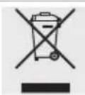
THIS APPLIANCE IS MARKED ACCORDING TO EUROPEAN DIRECTIVE 2002/96/EC ON WASTE ELECTRICAL AND ELECTRONIC EQUIPMENT (WEEE).
THIS DIRECTIVE DEFINES THE STANDARDS FOR THE COLLECTION AND RECYCLING OF WASTE ELECTRICAL AND ELECTRONIC EQUIPMENT APPLICABLE THROUGHOUT THE EUROPEAN UNION.
NEVER OBSTRUCT THE OPENINGS AND SLITS PROVIDED FOR VENTILATION AND HEAT DISPERSAL.

DO NOT REST ANY WEIGHT OR SIT ON THE OPEN DOOR OF THE APPLIANCE.

THE IDENTIFICATION PLATE WITH THE TECHNICAL DATA, SERIAL NUMBER AND BRAND NAME HAS BEEN VISIBLY AFFIXED TO THE APPLIANCE.
DO NOT REMOVE THIS PLATE FOR ANY REASON.

BEFORE THE APPLIANCE IS PUT INTO OPERATION, ALL THE PROTECTIVE FILMS APPLIED INSIDE OR OUTSIDE MUST BE REMOVED.

TAKE CARE THAT NO OBJECTS ARE STUCK IN THE DOOR OF THE OVEN.
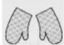
THE APPLIANCE BECOMES VERY HOT DURING USE. SUITABLE HEAT-PROOF GLOVES SHOULD BE WORN FOR ALL OPERATIONS.

DO NOT USE METALLIC SPONGES AND SHARP SCRAPERS AS THEY WILL DAMAGE THE SURFACES.
USE NORMAL NON-ABRASIVE PRODUCTS, INCLUDING WOODEN OR PLASTIC UTENSILS IF NECESSARY. RINSE THOROUGHLY AND DRY USING A SOFT CLOTH OR CHAMOIS LEATHER.
DO NOT ALLOW RESIDUES OF SUGARY FOODS (SUCH AS JAM) TO SET INSIDE THE OVEN. IF THEY ARE ALLOWED TO SET FOR TOO LONG, THEY COULD RUIN THE ENAMEL COVERING THE INSIDE OF THE OVEN.
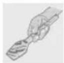
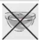
DO NOT USE PLASTIC KITCHENWARE OR CONTAINERS. THE HIGH TEMPERATURES INSIDE THE OVEN COULD MELT THE PLASTIC, DAMAGING THE APPLIANCE.
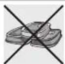
DO NOT USE SEALED TINS OR CONTAINERS IN THE APPLIANCE. OVERPRESSURE MAY OCCUR INSIDE THE CONTAINERS DURING COOKING, CREATING A DANGER OF EXPLOSION.
DO NOT LEAVE THE APPLIANCE UNATTENDED DURING COOKING PROCESSES WHERE FATS OR OILS COULD BE RELEASED. FATS AND OILS MAY CATCH FIRE.
DO NOT COVER THE BOTTOM OF THE OVEN WITH ALUMINIUM OR TINFOIL SHEETS DURING COOKING AND DO NOT PLACE PANS OR TRAYS ON IT TO AVOID DAMAGE TO THE ENAMELLED SURFACE.
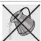
IF THE SURFACES ARE STILL VERY HOT DURING COOKING, DO NOT POUR WATER DIRECTLY ONTO THE TRAYS. THE STEAM COULD CAUSE SEVERE BURNS AND DAMAGE TO ENAMELLED SURFACES.

ALL COOKING OPERATIONS MUST TAKE PLACE WITH THE DOOR CLOSED.
2. SAFETY PRECAUTIONS
REFER TO THE INSTALLATION INSTRUCTIONS FOR THE SAFETY REGULATIONS FOR ELECTRIC OR GAS APPLIANCES AND VENTILATION FUNCTIONS.
IN YOUR INTERESTS AND FOR YOUR SAFETY THE LAW REQUIRES THAT THE INSTALLATION AND SERVICING OF ALL ELECTRICAL APPLIANCES ARE CARRIED OUT BY QUALIFIED PERSONNEL IN ACCORDANCE WITH THE REGULATIONS IN FORCE.
OUR APPROVED INSTALLERS GUARANTEE A SATISFACTORY JOB.
GAS OR ELECTRICAL APPLIANCES MUST ALWAYS BE DISCONNECTED BY SUITABLY SKILLED PEOPLE.

BEFORE CONNECTING THE APPLIANCE TO THE POWER GRID, CHECK THE DATA ON THE PLATE AGAINST THE DATA FOR THE GRID ITSELF.
BEFORE CARRYING OUT INSTALLATION/MAINTENANCE WORK, MAKE SURE THAT THE APPLIANCE IS NOT CONNECTED TO THE POWER GRID.
THE PLUG TO BE CONNECTED TO THE POWER SUPPLY CABLE AND ITS SOCKET MUST BE OF THE SAME TYPE AND CONFORM TO THE REGULATIONS IN FORCE. THE SOCKET MUST BE ACCESSIBLE AFTER THE APPLIANCE HAS BEEN BUILT IN. NEVER DISCONNECT THE PLUG BY PULLING ON THE CABLE.
IF THE POWER SUPPLY CABLE IS DAMAGED, CONTACT THE TECHNICAL SUPPORT SERVICE IMMEDIATELY AND THEY WILL REPLACE IT.
IT IS OBLIGATORY FOR ALL ELECTRICAL EQUIPMENT TO BE EARTHED ACCORDING TO THE METHODS LAID DOWN BY SAFETY REGULATIONS.

IMMEDIATELY AFTER INSTALLATION, CARRY OUT A BRIEF INSPECTION TEST, FOLLOWING THE INSTRUCTIONS BELOW. SHOULD THE APPLIANCE NOT FUNCTION, DISCONNECT IT FROM THE ELECTRICITY SUPPLY AND CALL THE NEAREST TECHNICAL SUPPORT CENTRE. NEVER ATTEMPT TO REPAIR THE APPLIANCE.
DO NOT USE OR LEAVE FLAMMABLE MATERIALS NEAR THE APPLIANCE OR IN THE FOOD WARMING COMPARTMENT.
DURING USE THE APPLIANCE BECOMES VERY HOT. TAKE CARE NOT TO TOUCH THE HEATING ELEMENTS INSIDE THE OVEN.

THIS APPLIANCE MAY NOT BE USED BY PEOPLE (INCLUDING CHILDREN) OF REDUCED PHYSICAL AND MENTAL CAPACITY, OR LACKING IN EXPERIENCE IN THE USE OF ELECTRICAL APPLIANCES, UNLESS THEY ARE SUPERVISED OR INSTRUCTED BY ADULTS RESPONSIBLE FOR THEIR SAFETY.
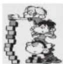
DO NOT LET CHILDREN GO NEAR THE APPLIANCE WHEN IT IS IN OPERATION OR PLAY WITH IT AT ANY TIME.

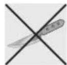
DO NOT INSERT POINTED METAL OBJECTS (CUTLERY OR UTENSILS) INTO THE SLITS IN THE APPLIANCE.
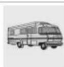
IF THE APPLIANCE IS INSTALLED ON CARAVANS OR BOATS, IT MUST NOT BE USED TO HEAT ROOMS.
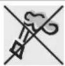
DO NOT USE STEAM JETS FOR CLEANING THE APPLIANCE. THE STEAM COULD REACH THE ELECTRONICS, DAMAGING THEM AND CAUSING SHORT-CIRCUITS.
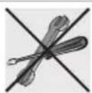
DO NOT MODIFY THIS APPLIANCE.
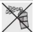
DO NOT SPRAY ANY SPRAY PRODUCTS NEAR THE ELECTRICAL APPLIANCE WHILE IT IS IN OPERATION. DO NOT USE SPRAY PRODUCTS WHILE THE PRODUCT IS STILL HOT.

The manufacturer cannot be held liable for damage to persons or things caused by failure to observe the above instructions, by interference with any part of the appliance or by the use of non-original spare parts.
3. ENVIRONMENTAL RESPONSIBILITY
3.1 Our environmental responsibility

Pursuant to Directives 2002/95/EC, 2002/96/EC and 2003/108/EC relating to the reduction of the use of hazardous substances in electrical and electronic appliances, as well as to the disposal of refuse, the crossed out bin symbol on the appliance indicates that at the end of the useful life of the product, it must be collected separately from other refuse. Therefore, at the end of the products working life, the user must deliver it to the appropriate differentiated collection centres for electrical and electronic waste, or deliver it back to there tailer when purchasing an equivalent product, on a one for one basis. Adequate differentiated collection for the subsequent forwarding of the decommissioned product to recycling, processing and ecologically compatible disposal contributes to avoiding possible negative effects on the environment and on health, and promotes recycling of the appliance's constituent materials. Illicit disposal of the product by the user will lead to the application of administrative sanctions.
The product does not contain substances in quantities sufficient to be considered hazardous to health and the environment, in accordance with current European directives.
3.2 Your environmental responsibility
Our products packing is made of non-polluting materials, which are therefore compatible with the environment and recyclable. Please help by disposing of the packaging correctly. You can obtain the addresses of collection, recycling and disposal centres from your retailer or from the competent local organisations.

Do not discard the packaging or any part of it, or leave it unattended. It can constitute a suffocation hazard for children, especially the plastic bags.
Your old appliance also needs to be disposed of correctly.
Important: hand over your appliance to the local agency authorised for the collection of electrical appliances no longer in use. Correct disposal enables intelligent recovery of valuable materials.
Before disposing of your appliance it is important to remove doors and leave shelves in the same position as for use, to ensure that children cannot accidentally become trapped inside during play. It is also necessary to cut the connecting cable to the power grid, removing it along with the plug.
4. GET TO KNOW YOUR OVEN
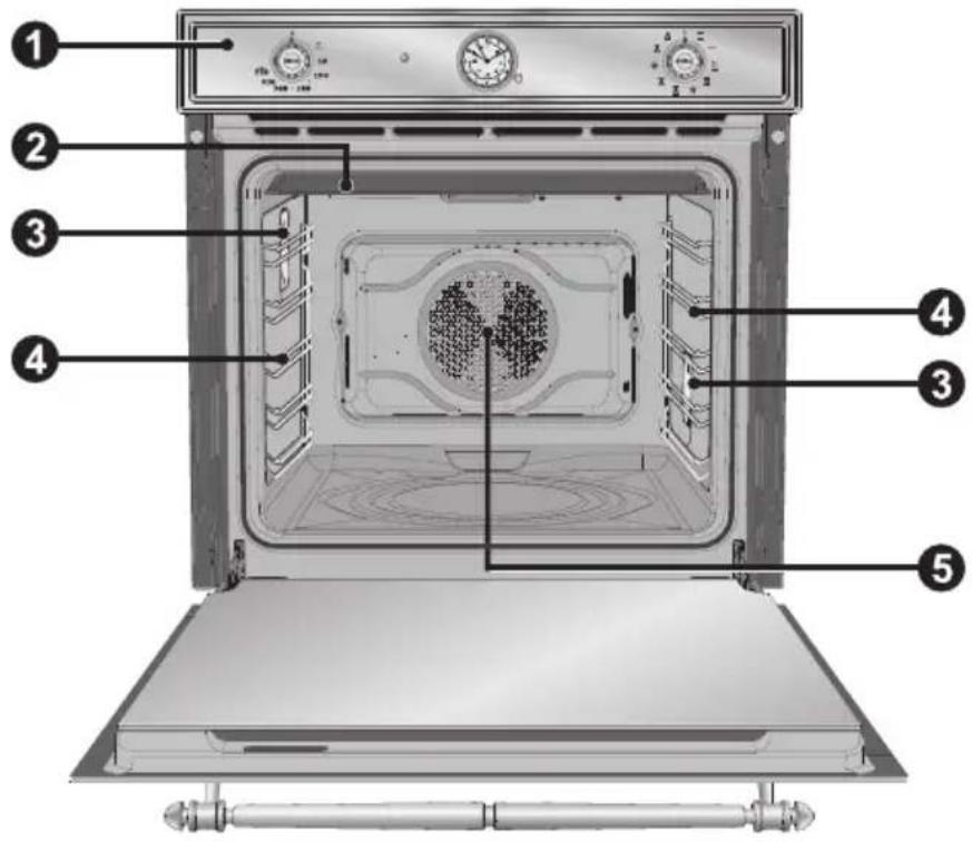
text_image
Labeled diagram of an oven interior showing numbered components for identification1 CONTROL PANEL
2 ROOF LINER
3 LAMP
4 RACK AND TRAY SUPPORT RUNNERS
5 OVEN FAN
5. AVAILABLE ACCESSORIES
NOTE: Some models are not provided with all accessories.
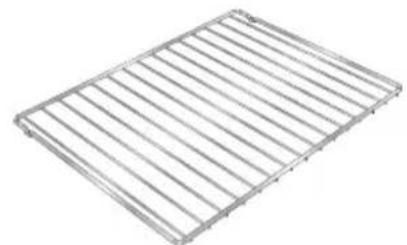
Rack: for holding cooking containers.
Tray rack: to be placed over the top of the oven tray; for cooking foods which may drip.
Oven tray: for collecting fat from foods placed on the rack above.
Deep oven tray: for baking cakes, pizza and oven desserts.
natural_image
Metal wire rack structure with parallel slats (no text or symbols)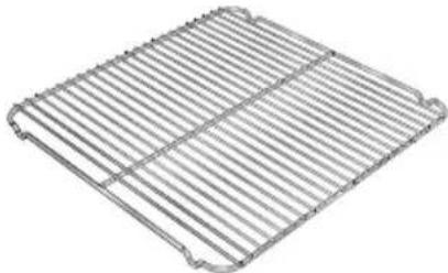
natural_image
Metallic rack structure with vertical slats and mounting brackets (no text or symbols)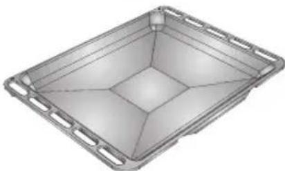
natural_image
3D rendering of a rectangular metal tray with side brackets and a central hole (no text or symbols)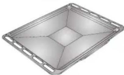
natural_image
3D rendering of a rectangular metal tray with side brackets and internal compartments (no text or symbols)
• Accessories available on request:
Original supplied and optional accessories may be ordered from any Authorised Support Centre.
- Use original accessories only.
5.1 Using the rack
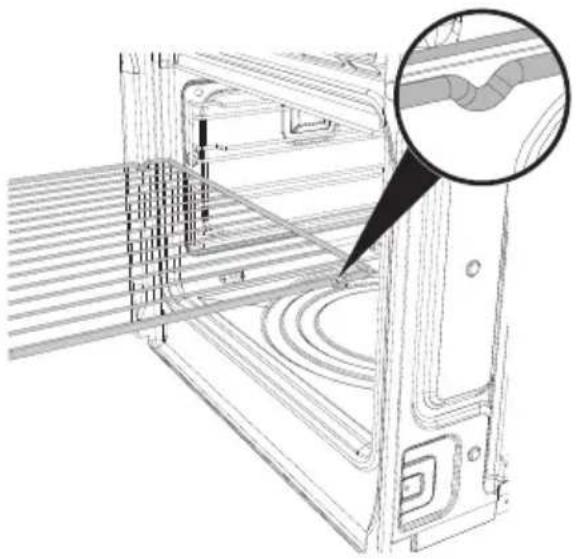
The racks are equipped with a mechanical safety lock which prevents them from being taken out accidentally. To insert the rack correctly, check that the lock is facing downwards (as shown in the figure below).
To take it out, lift the front edge of the rack slightly while sliding it out on the side runners.
The mechanical lock must always face the back of the oven.
natural_image
Technical line drawing of a mechanical assembly with a magnified inset showing a curved component detail (no text or symbols)
Insert racks and trays fully into the oven until they come to a stop.
5.2 Using the support rack
The support rack is inserted into the tray (as shown in the figure).
Using this, foods can be cooked and the fat can be collected separately from the food which is being cooked.

natural_image
3D rendering of a metal grid-patterned tray or enclosure with mounting holes (no text or symbols visible)6. USING THE OVEN
6.1 Before using the appliance

- Remove any labels (apart from the technical data plate) from trays, dripping pans and the cooking compartment.
- Remove any protective film from the outside or inside of the appliance, including from accessories such as trays, dripping pans, the pizza plate or the base cover.
- Before using the appliance for the first time, remove all accessories from the oven compartment and wash them as indicated in “8. CLEANING AND MAINTENANCE”.

Heat the empty appliance to the maximum temperature in order to remove any manufacturing residues which could affect the food with unpleasant odours.
6.2 General Description
6.2.1 Oven runners
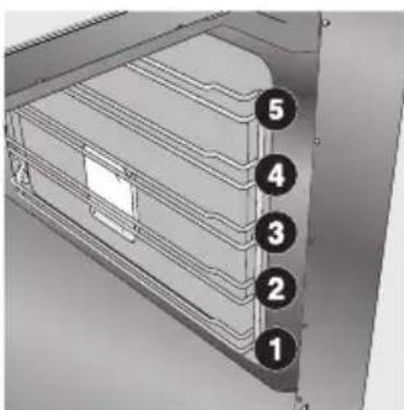
The oven features 5 runners for positioning trays and racks at different heights. The insertion heights are numbered from the bottom upwards (see figure).
text_image
Technical diagram of a mechanical device with numbered components labeled 1 through 56.2.2 Cooling system
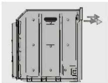
The appliance is equipped with a cooling system which comes into operation as soon as a cooking function starts. The fan causes a steady outflow of air from above the door which may continue for a brief period of time even after the oven has been turned off.
natural_image
Technical line drawing of a mechanical housing or enclosure with mounting holes and a directional arrow (no text or symbols)6.2.3 Internal oven lights
The oven lights come on when the door is opened (sone models only) or any function or recipe is selected.
6.3 Warnings and general advice for usage

All cooking operations must be carried out with the door closed.
During cooking, do not cover the bottom of the oven with aluminium or tin foil and do not place pans or oven trays on it as this may damage the enamel coating. If you wish to use greaseproof paper, place it so that it will not interfere with the hot air circulation inside the oven.
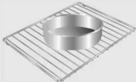
For the best cooking results, we recommend placing cookware in the centre of the rack.
natural_image
3D rendering of a metallic cylindrical bowl placed on a wire rack (no text or symbols)
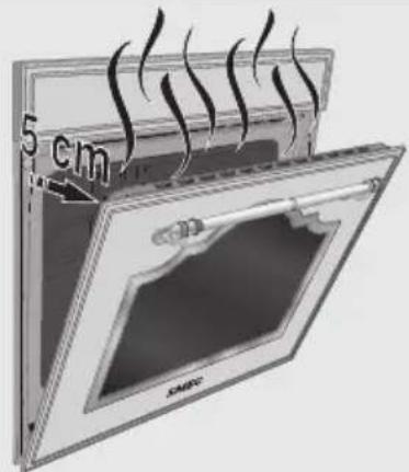
To prevent any steam in the oven from causing problems, open the door in two stages: half open (5 cm approx.) for 4-5 seconds and then fully open. If you need to access the food, always leave the door open for as short a time as possible to prevent the temperature in the oven from falling and ruining the food.
text_image
5 cm SMRCTo prevent excessive amounts of condensation from forming on the internal glass, hot food should not be left inside the oven for too long after cooking.
6.4 Description of the controls on the front panel
All the appliances control and monitoring devices are located together on the front panel.

text_image
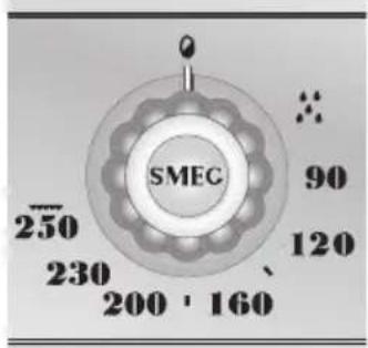
1 2 3 4 SMBC 50 120 230 280 / 160 SMBC SMBC 230 280 / 160OVEN THERMOSTAT KNOB

This knob can be used to select the cooking temperature.
Turn the knob clockwise to the desired value, between 50°C and 250°C.
This knob can also be used to select the
temperature for Vapor Clean

text_image
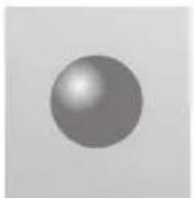
SMEC 250 230 200 160 90 120THERMOSTAT LIGHT

When this is flashing, it indicates that the oven is heating up to reach the temperature set using the thermostat knob. Once the oven has reached the set temperature:
When the light flashes regularly, it means that the temperature inside the oven is kept steady on the set level.
PROGRAMMING CLOCK

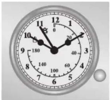
The programming clock can be used to display the current time (multifunction models only) or to set a timer or cooking programme (pyrolytic models only).
natural_image
Analog clock face showing 10:30 with hour and minute hands (no text or symbols beyond numerals)FUNCTION KNOB

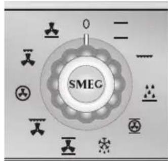
Turn the knob clockwise or anti-clockwise to select a function from the following options: (See 7. COOKING WITH THE OVEN).
text_image
SMEG6.5 Programming clock
text_image
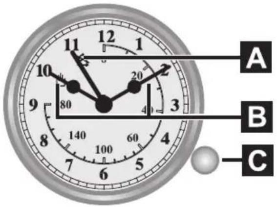
A B CA
Pointer for manual or timed cooking
B Hours - minutes pointers
C Small adjustment knob
The programmer enables manual cooking or the timer to be selected, or the cooking time to be set.
Select the desired function and cooking temperature before setting the cooking time.
6.5.1 Setting the time
To set the correct time, pull out knob A and turn it clockwise.
6.5.2 Manual cooking
For manual cooking, turn the small knob C clockwise until pointer A is aligned
with symbol

6.5.3 Timed cooking
To set the cooking time, turn knob C clockwise until pointer A reaches the desired length of time (maximum 180 minutes).
6.5.4 End of cooking
The oven will switch off automatically and a buzzer will start to sound simultaneously.
6.5.5 Stopping the buzzer
To switch off the buzzer, turn knob C clockwise until pointer A is aligned with

The programmer enables manual cooking or the timer to be selected, or the cooking time to be set.
Select the desired function and cooking temperature before setting the cooking time.
7. COOKING WITH THE OVEN
STATIC:

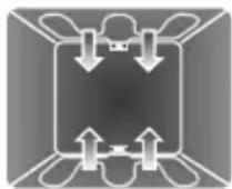
As the heat comes from above and below at the same time, this system is particularly suitable for certain types of food. Traditional cooking, also known as static or thermal radiation cooking, is suitable for cooking just one dish at a time. Perfect for all types of roasts, bread and cakes and in any case particularly suitable for fatty meats such as goose and duck.
GRILL:

The heat coming from the grill element gives perfect grilling results, especially for thin and medium thickness meat and, in combination with the rotisserie (when present), it allows the food to be browned evenly at the end of cooking. Perfect for sausages, ribs and bacon. This function enables large quantities of food, particularly meat, to be grilled evenly. (3rd or 4th runner).
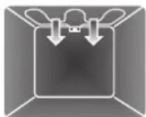
TURBO:

The combination of fan-assisted cooking and traditional cooking enables different foods to be cooked on several levels extremely quickly and efficiently, without any transfer of smells and flavours.
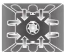
Perfect for large volumes that call for intense cooking.
(For multiple-level cooking, you are advised to use the 2nd and 4th runners.)
DEFROSTING: (on some models only)

Rapid defrosting is helped by switching on the fan and the top heating element to ensure uniform distribution of low-temperature air inside the oven.
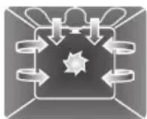
FAN-ASSISTED STATIC:

The operation of the fan, combined with traditional cooking, ensures uniform cooking even with complex recipes. Perfect for biscuits and cakes, even when simultaneously cooked on several levels. (For multiple-level cooking, you are advised to use the 2nd and 4th runners.)
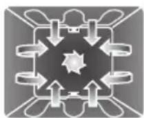
FAN-ASSISTED GRILL:

The air produced by the fan softens the strong heatwave generated by the grill, giving perfect grilling results even with very thick foods. Perfect for large cuts of meat (e.g. shin of pork).
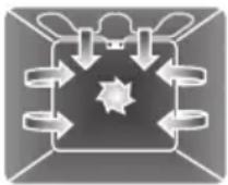
CIRCULAR:

The combination of the fan and the circular element (incorporated in the rear of the oven) enables different foods to be cooked on several levels, as long as they need the same temperature and cooking time. Hot air circulation ensures instant and uniform distribution of heat. It will be possible, for instance, to cook fish, vegetables and biscuits simultaneously (on different levels) without mixing smells and flavours.
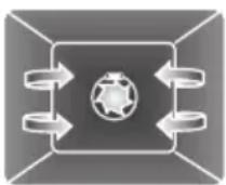
(For multiple-level cooking, you are advised to use the 2nd and 4th runners.)
FAN-ASSISTED SMALL GRILL:

Through the combined action of the fan and the
heat of the central element only, this function is perfect for rapid cooking and cooking au gratin of small quantities of food (particularly meats), by bringing together the dietary advantages of the grill and the even cooking of the fan.
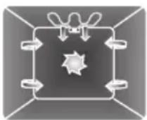
FAN-ASSISTED BOTTOM:

The combination of the fan with just the lower heating element allows cooking to be completed more rapidly. This system is recommended for sterilising or for finishing off the cooking of foods which are already well-cooked on the surface, but not inside, which therefore need a little more heat. Perfect for any type of food.
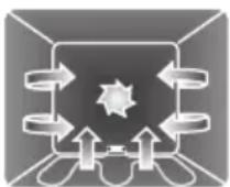
In pyrolytic models, the special defrosting and proving functions are brought together under the same function (see “7.3 Defrosting function” for further details).
7.1 Cooking advice and instructions
7.1.1 General advice
We recommend preheating the oven before putting the food in.
- For cooking on several levels, we recommend using a fan-assisted function

text_image
( ) to achieve uniform cooking at all heights.- In general, it is not possible to shorten the cooking times by increasing the temperature (the food could be well-cooked on the outside and undercooked on the inside).
7.1.2 Advice for cooking meat
- Cooking times, especially for meat, vary according to the thickness and quality of the food and to consumer taste.
- We recommend using a meat thermometer for meat when roasting it. Alternatively, simply press on the roast with a spoon: if it is hard, it is ready; if not, it needs another few minutes cooking.
7.1.3 Advice for cooking desserts and biscuits
- Use dark metal moulds for desserts: they help to absorb the heat better.
- The temperature and the cooking duration depend on the quality and consistency of the dough.
- Check whether the dessert is cooked all the way through: at the end of the cooking time, put a toothpick into the highest point of the dessert. If the dough does not stick to the toothpick, the dessert is cooked.
- If the dessert collapses when it comes out of the oven, on the next occasion reduce the set temperature by about 10 °C, selecting a longer cooking time if necessary.
7.1.4 Advice for defrosting and proving
- We recommend positioning frozen foods in a lidless container on the first runner of the oven.
- The food must be defrosted without its wrapping.
- Lay out the foodstuffs to be defrosted evenly, not overlapping.
- When defrosting meat, we recommend using a rack positioned on the second runner with the food on it and a tray positioned on the first runner. In this way, the liquid from the defrosting food drains away from the food.
- The most delicate parts can be covered with aluminium foil.
- For successful proving, a container of water should be placed in the bottom of the oven.
7.1.5 Advice for cooking with the Grill and the Fan-assisted grill
- Using the Grill function, meat can be grilled even when it is put into the oven cold; preheating is recommended if you wish to change the effect of the cooking.
- With the Fan-assisted grill function, however, we recommend that you preheat the oven before grilling.
• We recommend placing the food at the centre of the rack.
7.2 To save energy
To save energy during use of the appliance, the following instructions may be followed:
- Stop cooking a few minutes before the time normally used. Cooking will continue for the remaining minutes with the heat which has accumulated inside the oven.
- Reduce any opening of the door to a minimum to avoid heat dispersal.
- Use the ECO function for cooking on a single runner.
- Keep the inside of the appliance clean at all times.
7.3 Defrosting function
In multifunction models, the defrosting function enables any type of food to be
defrosted. To start defrosting, turn the oven function knob to , then a ventilation system will go into operation to ensure uniform distribution of the ambient temperature inside the oven.
The defrosting time will depend on the quantity of food to be defrosted.
7.4 Cooking tables
| DISHES WEIGHT FUNCTION | ||
| FIRST COURSES | ||
| LASAGNE 3 kg Static |  | |
| OVEN-BAKED PASTA Static | ||
| MEAT | ||
| ROAST VEAL 1 kg Fan-assisted static |  | |
| LOIN OF PORK 1 kg Fan-assisted static | ||
| SHOULDER OF PORK 1 kg Turbo |  | |
| ROAST RABBIT 1 kg Circular |  | |
| TURKEY BREAST 1 kg Fan-assisted static |  | |
| ROAST NECK OF PORK 1 kg Turbo |  | |
| ROAST CHICKEN 1 kg Turbo |  | |
| GRILLED MEATS | ||
| PORK CHOPS |  Fan-assisted grill Fan-assisted grill | |
| FILLET OF PORK |  Grill Grill | |
| FILLET OF BEEF |  Grill Grill | |
| LIVER |  Fan-assisted grill Fan-assisted grill | |
| SAUSAGES |  Fan-assisted grill Fan-assisted grill | |
| MEAT BALLS |  Grill Grill | |
| FISH | ||
| SALMON TROUT 0.7 kg | Fan-assisted bottom | |
| RUNNER POSITION FROM BOTTOM | TEMPERATURE °C | TIME IN MINUTES | |
| 1 or 2 220 - 2 | 30 40 - 50 | ||
| 1 or 2 220 - 2 | 30 40 | ||
| 2 180 - 190 | 70 - 80 | ||
| 2 180 - 190 | 70 - 80 | ||
| 2 180 - 190 | 90 - 100 | ||
| 2 180 - 190 | 70 - 80 | ||
| 2 180 - 190 | 110 - 120 | ||
| 2 180 - 190 | 190 - 210 | ||
| 2 190 - 200 | 60 - 70 | ||
| 1ST SURFACE | 2ND SURFACE | ||
| 4 250 - 280 | 7 - 9 5 - 7 | ||
| 3 250 - 280 | 9 - 11 5 - 9 | ||
| 3 250 - 280 | 9 - 11 9 - 11 | ||
| 4 250 - 280 | 2 - 3 2 - 3 | ||
| 3 250 - 280 | 7 - 9 5 - 6 | ||
| 3 250 - 280 | 7 - 9 5 - 6 | ||
| 2 160 - 170 | 35 - 40 | ||
| DISHES WEIGHT FUNCTION | |||
| PIZZA Fan-assisted static |  | ||
| BREAD Circular |  | ||
| FOCACCIA Turbo |  | ||
| DESSERTS | |||
| DOUGHNUT Fan-assisted static |  | ||
| FRUIT TART Fan-assisted static |  | ||
| FRUIT TART Static |  | ||
| SHORT PASTRY Circular |  | ||
| JAM TARTS Turbo |  | ||
| PARADISE CAKE Fan-assisted static |  | ||
| PARADISE CAKE Static |  | ||
| ECLAIR Turbo |  | ||
| LIGHT SPONGE CAKE Circular |  | ||
| RICE PUDDING Turbo |  | ||
| RICE PUDDING Static |  | ||
| CROISSANTS Circular |  | ||
| APPLE PIE |  | Static | |
| CROISSANTS (on multiple runners) |  |  [GYSX] [GYSX] | |
| SHORT PASTRY BISCUITS (on multiple runners) |  |  [BD3T] [BD3T] | |
The times indicated in the following tables do not include the preheating times and are provided as a guide only.
| RUNNER POSITION FROM BOTTOM | TEMPERATURE °C | TIME IN MINUTES |
| 1 250 - 280 | 6 -10 | |
| 2 190 - 200 | 25 -30 | |
| 2 180 - 190 | 15 -20 | |
| 2 160 55 - 60 | ||
| 2 160 30 - 35 | ||
| 2 170 35 - 40 | ||
| 2 160 - 170 | 20 - 25 | |
| 2 160 20 - 25 | ||
| 2 160 55 - 60 | ||
| 2 170 50 - 60 | ||
| 2 150 - 160 | 40 - 50 | |
| 2 150 - 160 | 45 - 50 | |
| 2 160 40 - 50 | ||
| 2 170 50 - 60 | ||
| 2 160 25 - 30 | ||
| 3 | 1 | 8 0 |
| 2 and 4 160 - 170 16 - 20 | ||
| 2 and 4 160 - 170 16 - 20 | ||
8. CLEANING AND MAINTENANCE

NEVER USE A STEAM JET FOR CLEANING THE APPLIANCE.
8.1 Cleaning stainless steel
To keep stainless steel in good condition it should be cleaned regularly after use. Let it cool first.
8.2 Ordinary daily cleaning
To clean and preserve the stainless steel surfaces, always use only specific products that do not contain abrasives or chlorine-based acids.
How to use: pour the product onto a damp cloth and wipe the surface, rinse thoroughly and dry with a soft cloth or chamois leather.
8.3 Food stains or residues
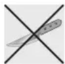
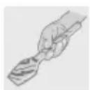
Do not use metallic sponges or sharp scrapers as they will damage the surface.
Use normal non-abrasive products and a wooden or plastic tool if necessary. Rinse thoroughly and dry with a soft cloth or chamois leather.
Do not allow residues of sugary foods (such as jam) to set inside the oven. If left to set for too long, they might damage the enamel lining of the oven.
8.4 Cleaning the door glazing
The glass in the door should always be kept thoroughly clean. Use absorbent kitchen roll; remove stubborn dirt with a damp sponge and an ordinary detergent.

Do not use abrasive or corrosive cleaners for cleaning the door glazing.
(e.g. powder products, oven-cleaner sprays, stain removers and metal scouring pads).
Do not use rough or abrasive materials or sharp metal scrapers to clean the oven's glass doors since they may scratch the surface and cause the glass to shatter.
8.5 Cleaning the inside of the oven
For the best oven upkeep, clean it regularly after having allowed it to cool.
• Take out all removable parts.
- Clean the oven racks with hot water and non-abrasive detergent. Rinse and dry.
- For easier cleaning, the door can be removed (see "9.2 Removing the door").

natural_image
Illustration of a hand cleaning a metal tray with a cloth, showing internal structure and spray application (no text or symbols)
The oven should be operated at its maximum temperature for about 15-20 minutes after the use of specific products, to burn off the residues left inside the oven. When the operation is complete, damp parts should be dried thoroughly.
8.6 Removing guide frames
text_image
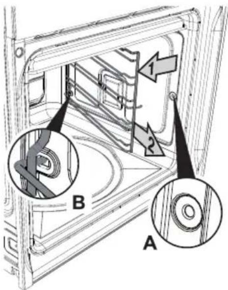
Technical diagram of a mechanical assembly with labeled parts A and B, showing internal components and directional arrows.Removing the guide frames makes it easier to clean the side parts of the oven, and it also needs to be done whenever the automatic cleaning cycle is used (only available on some models).
- To remove the guide frames, pull the frame towards the inside of the oven to unhook it from its housing A, then slide it out of the seats at the back B.
- When cleaning is complete, repeat the above procedures in reverse order to put the guide frames back in.
Refer to the following diagram for setting the cleaning cycle duration:
8.7 Vapor Clean: assisted cleaning

Vapor Clean is an assisted cleaning procedure which facilitates the removal of dirt. Thanks to this process, it is possible to clean the inside of the oven very easily. The dirt residues are softened by the heat and water vapour for easier removal afterwards.

Before starting the assisted cleaning cycle, make sure that the oven does not contain any foods or large spills from previous cooking operations.

Carry out assisted oven cleaning operations only when the oven is cold.
8.7.1 Before starting the assisted cleaning cycle
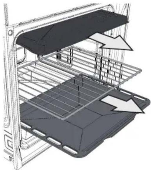
- Completely remove all accessories from inside the oven. The roof liner is not considered an accessory and must therefore be kept inside the oven.
natural_image
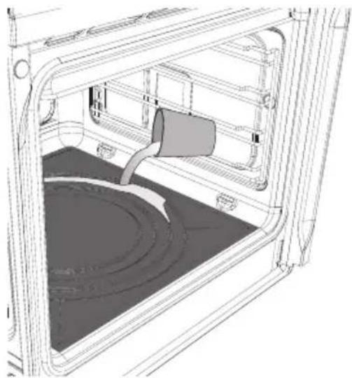
3D technical illustration of a poultry farm interior with overhead crane structure and structural framework (no text or symbols)- Pour approx. 400 cc of water onto the floor of the oven (as shown in the figure). Make sure it does not overflow out of the cavity.
natural_image
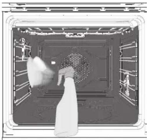
Technical line drawing of a vehicle interior frame with no visible text or symbols- Spray a water and washing up liquid solution inside the oven using a spray nozzle. Direct the spray against the side walls, roof, base and deflector.
natural_image
Interior view of a large industrial or laboratory chamber with a central circular structure and two hanging objects (no visible text or symbols)- At the end of this process, close the door and set the cleaning cycle.
Do not spray excessive amounts of the water and washing up liquid solution. We recommend spraying approx. 20 times at the most.
8.7.2 Setting the assisted cleaning cycle
Once the preparations have been made for the assisted cleaning cycle, proceed as follows.
Models with programmer clock:
- turn the oven function knob and the oven thermostat knob to

Vapor Clean function;
- set a cooking time of 18 minutes using the cooking duration procedure described in more detail in "6.5.3 Timed cooking";
At the end of the assisted cleaning cycle, the timer will switch off the oven heating elements.
8.7.3 End of the assisted cleaning cycle
The water remaining at the end of the assisted cleaning cycle cannot be left inside the oven for long (for example overnight).
You are advised to wear a pair of gloves during these processes.
At the end of the cleaning cycle, open the door and wipe away the less stubborn dirt with a microfibre cloth. Use an anti-scratch sponge with brass filaments on tougher encrustations.
We recommend removing the door as described in “9.2 Removing the door” to facilitate access to restricted spaces.
For improved hygiene and to avoid food being affected by any unpleasant odours, we recommend that the oven is dried using a fan function at 160^ C for approximately 10 minutes. To set the function, see “7. COOKING WITH THE OVEN”.
9. EXTRAORDINARY MAINTENANCE
The oven may require extraordinary maintenance or replacement of parts subject to wear such as gaskets, bulbs, etc. The following instructions describe how to carry out these minor maintenance operations.
Before any intervention that requires access to live parts, disconnect the power supply of the appliance.
If a problem cannot be resolved through ordinary maintenance or in the case of other types of fault, contact your local technical support centre.
9.1 Replacing the light bulb
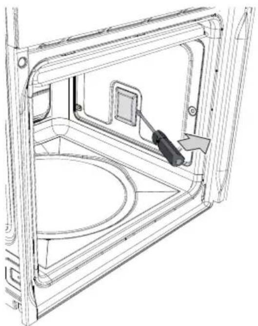
If a light bulb needs to be replaced because it is worn or burnt out, remove the guide frames; see "8.6 Removing guide frames".
Then remove the bulb cover using a tool (e.g. a screwdriver).
natural_image
Technical line drawing of a mechanical assembly with a screwdriver inserted, showing internal components and a circular base (no text or symbols)Remove the bulb by sliding it out as shown.
On some models only: the bulbs are halogen bulbs, so do not touch them directly with your fingers, wrap them in an insulating material.
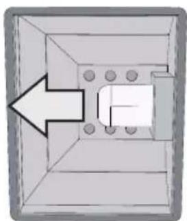
Replace the bulb with one of the same type (40W). Replace the cover correctly, so that the moulded part of the glass is facing the door.
natural_image
Pure diagram of a 3D rectangular block with internal components and an arrow pointing to one corner (no text or symbols)
Press the cover down as far as it will go so that it attaches completely to the bulb support.
9.2 Removing the door
9.2.1 With pins
Open the door completely.
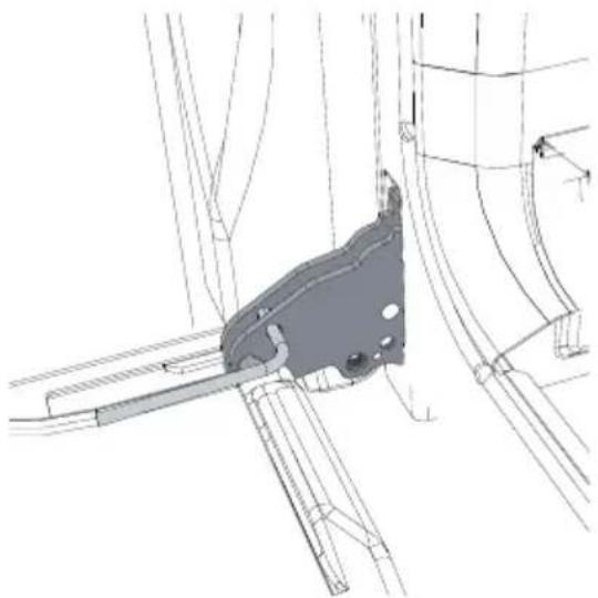
Insert two pins into the holes indicated A in the two hinges towards the back of them until they engage.
natural_image
Technical line drawing of a mechanical bracket assembly (no text or symbols)Grasp the door on both sides with both hands, lift it forming an angle of around 30^ and remove it.
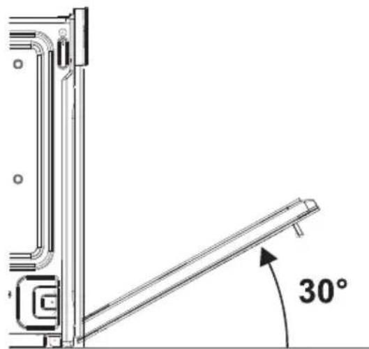
text_image
30°To reassemble the door, put the hinges in the relevant slots in the oven, making sure that grooved sections C are resting completely in the slots. Lower the door and once it is in place remove the pins from the holes in the hinges.
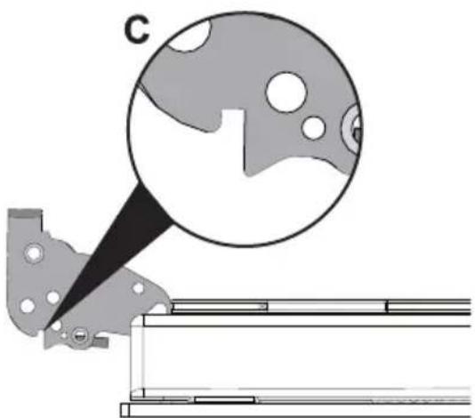
natural_image
Mechanical assembly diagram showing a bracket with a magnified circular detail (no text or symbols)9.3 Removing the door seal
For multifunction models only:
To permit thorough cleaning of the oven, the door seal may be removed.
There are fasteners on all four sides to attach it to the edge of the oven. Pull the edges of the seal outwards to detach the fasteners.
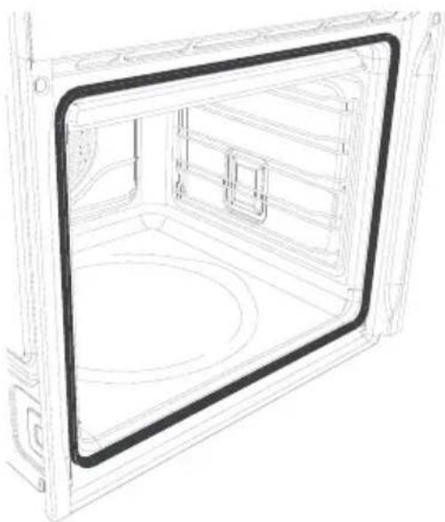
natural_image
Line drawing of a 3D cabinet interior with a black frame and circular base (no text or symbols)9.4 Removing the internal glass panels
The glass in the door should always be kept thoroughly clean. To facilitate cleaning, it is possible to remove the door (see 9.2 Removing the door) and place it on a canvas, or open it and lock the hinges in order to extract the glass panels.
The glass panels of the door can be completely removed by following the instructions provided below.

Warning: before removing the glass panels, make sure that at least one of the door's hinges has been locked in the open position as described in "9.2 Removing the door". This operation may have to be repeated during the glass removal process if the door is accidentally freed.

Removing the internal glass panel:
- Remove the internal glass panel by pulling it upwards, following the movement indicated by the arrows. Doing this detaches the 4 pins attached to the glass from their slots in the oven door.
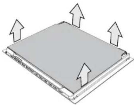
natural_image
3D diagram of a rectangular electronic component with upward arrows indicating orientation (no text or symbols)
Removing the middle glass panes: (pyrolytic models)
- There are two middle glass panels in pyrolytic models, attached using 4 small locks. Remove the middle panels by lifting them upwards.
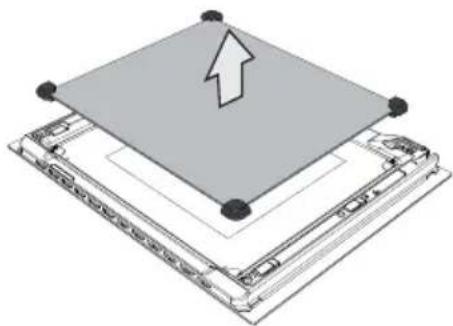
natural_image
3D diagram of a layered electronic device with an upward arrow indicating a component (no text or symbols present)(multifunction models)
- Multifunction models have a single middle panel. Remove the intermediate panel by lifting it upwards.

Cleaning:
- It is now possible to clean the external glass panel and the panels removed previously. Use absorbent kitchen roll. In the case of stubborn dirt, wash with a damp sponge and neutral detergent.
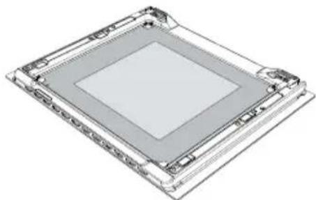
natural_image
3D technical illustration of a layered electronic component or package structure (no text or symbols visible)
Replacing the glass panels:
- Replace the panels in the reverse of the order in which they were removed.
- Reposition the internal glass panel, taking care to centre and insert the 4 pins attached to the glass into their slots in the oven door by applying slight pressure.
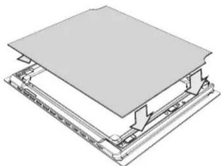
natural_image
Diagram of a layered electronic device with a flat top and internal components, showing no text or symbols.10. INSTALLING THE APPLIANCE
10.1 Electrical connection

The identification plate bearing the technical data, serial number and brand name is visibly positioned on the appliance.
Do not remove this plate for any reason.
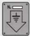
The appliance must be connected to earth in compliance with electrical system safety regulations.
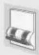
If the appliance is connected to the power supply network by means of a fixed connection, install a multipolar cut-out device on the power supply line, in accordance with the installation rules, located near the appliance and in an easily reachable position.
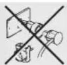
If a plug and socket connection is being used, make sure that the plug and socket are compatible. Avoid use of adapters and shunts as these could cause overheating and a risk of burns.
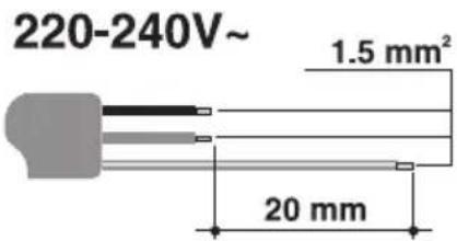
Operation at 220-240 V\~: use a H05V2V2-F type three-core cable (3 x 1.5 mm ^4 ).
text_image
220-240V~ 1.5 mm² 20 mmThe end to be connected to the appliance must have an earth wire (yellow-green) at least 20 mm longer than the others.
WARNING: The values indicated above refer to the cross-section of the internal conductor.
10.2 Cable replacement
Should the supply cable need replacing, remove the back guard by unscrewing the screws to gain access to the terminal.
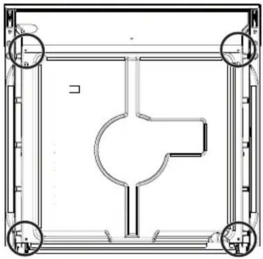
Replace the cable. The cable cross-section must be no less than 1.5 mm^2 (3 x 1.5).
Make sure that the cables (for the oven or any hob) follow the best route in order to avoid any contact with the oven.
natural_image
Technical line drawing of a mechanical or architectural component with symmetrical supports and central cutout (no text or symbols)
WARNING: The tightening torque of the screws of the terminal supply wires must be 1.5 - 2 Nm.
10.3 Positioning the oven

Never use the oven door to lever the oven into place when fitting. Avoid exerting too much pressure on the oven door when open.
We recommend installing the oven with the help of a second person.
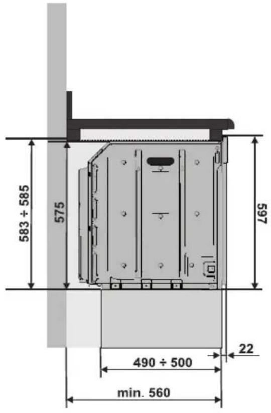
The base on which the oven is resting must be complete as shown in the illustrations below.
The oven is designed for mounting into any piece of furniture as long as it is heat-resistant.
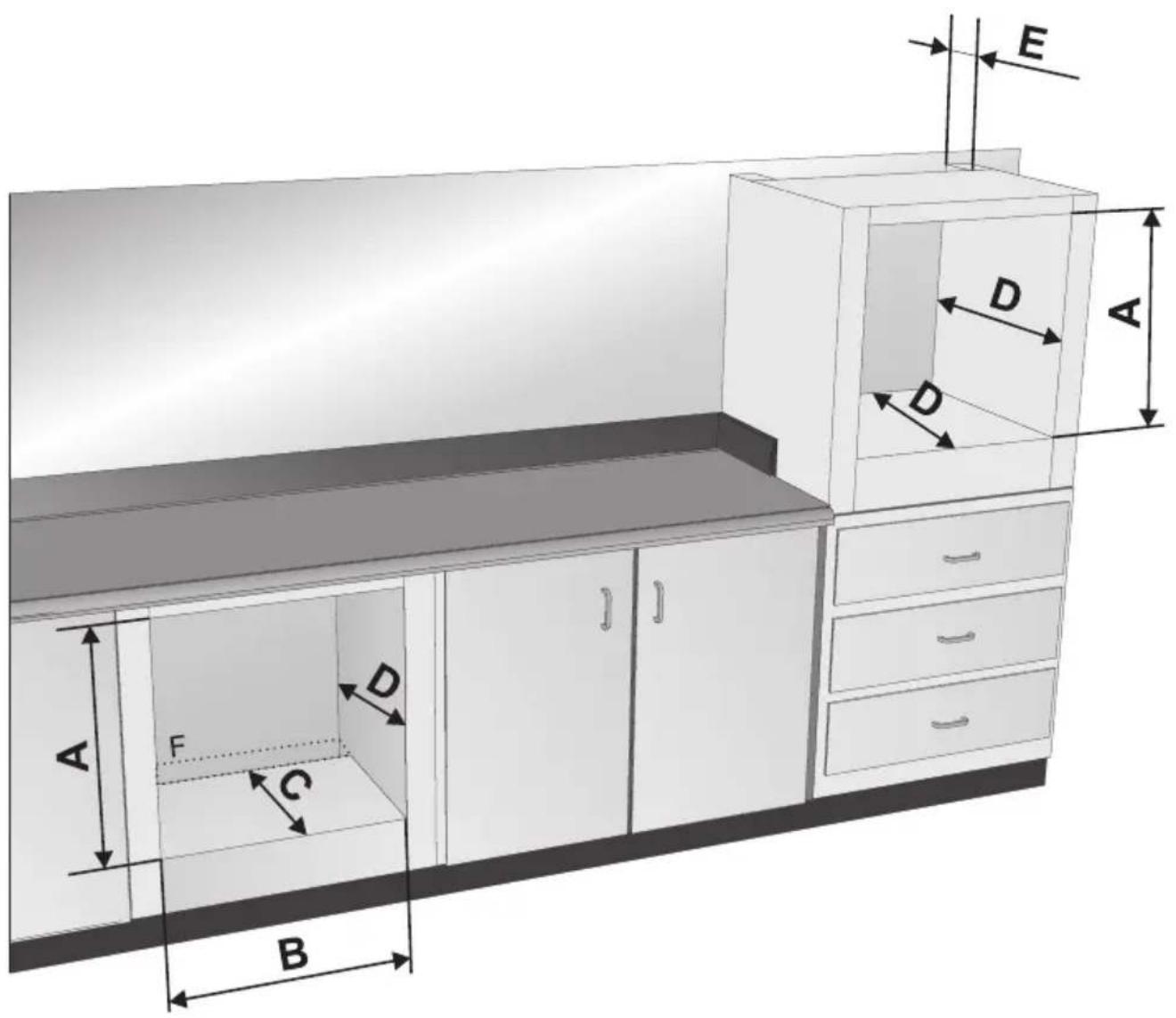
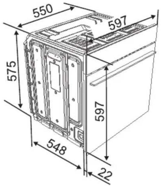
Proceed according to the dimensions shown in figures 1, 2 and 3.
For installing under a work top, follow the dimensions given in figures 1 and 2. For installing under a work top with combined cooking hobs, ensure a minimum clearance from any side walls of at least 110 mm.
For installing in tall units, comply with the dimensions shown in figures 1 and 2, bearing in mind that the top/rear of the unit must have an opening 35-40 mm deep.
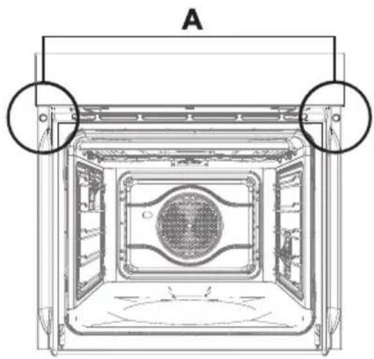
Remove the screw covers on the frame and screw in the 2 screws A (fig. 5) to fix the appliance to the unit. Replace the screw covers. For installing beneath a countertop hob, allow for a rear and bottom clearance as shown in figure 1 (ref. F).
See the relevant instructions for fitting and securing the appliance.
FIG.1
text_image
A F C B D D A E| A B C D E | |||||
| Measurements (mm) | 583 ÷ 585 | 554 ÷ 564 | 490 ÷ 500 | 560 min. | 35 ÷ 40 |
FIG. 2 FIG. 3
text_image
583 ÷ 585 575 597 490 ÷ 500 22 min. 560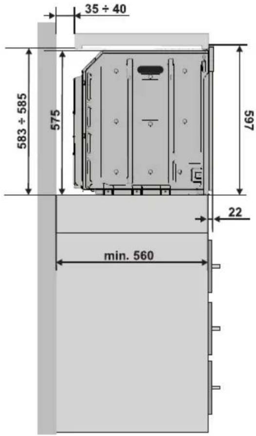
text_image
35 ÷ 40 583 ÷ 585 575 597 22 min. 560FIG. 4 FIG. 5
text_image
550 597 575 548 22 597