GS - Scooter VESPA - Free user manual and instructions
Find the device manual for free GS VESPA in PDF.


User questions about GS VESPA
0 question about this device. Answer the ones you know or ask your own.
Ask a new question about this device
Download the instructions for your Scooter in PDF format for free! Find your manual GS - VESPA and take your electronic device back in hand. On this page are published all the documents necessary for the use of your device. GS by VESPA.
USER MANUAL GS VESPA
To keep your Vespa in perfect running order and not to invalidate the guarantee offered by the contract, it is advisable to entrust repairs only to Retailers or authorized service stations, recognisable by the apposite sign.
Demand exclusively genuine Piaggio spare parts.
All PIAGGIO spares are made of the same material, have undergone the same machining operations and inspection as the components of your VESPA. This means guarantee of long life and normal performance of your machine and for your personal safety.
Special care should be taken with regard to fuel mixture which should be of a good quality gasoline and oil of make, grade and in the amount prescribed in this booklet, page 29.
Avoid use of additives and vegetable oils.
ADVERTENCIA
Performance and main specifications . . . » 9
Electrical equipment 26
Standard tools and accessories . . . . . » 28
Operational instructions . . . . . . . » 29
Maintenance 44
Lubrication chart 50
Fault finding and functional irregularities . . » 52
INDICE DE LAS NORMAS PRINCIPALES
natural_image
Side profile illustration of a classic scooter with open body, front wheel, and back cover (no text or symbols)Fig. 1 - Moto Vespa G. S.
Fig. 1 - Vespa G.S.
INTRODUCTION
The Piaggio wishes to thank you for your choice of this excellent model of Vespa and is convinced that it will be to your complete satisfaction.
You will no doubt be able to appreciate the excellent qualities of the Vespa G.S. both from a sporting and touristic point of view (high speed, brisk acceleration, excellent suspension and road holding qualities, silent running, extreme elegance etc). Long and tortuous runs on the G.S. will not tire you. You will immediately note its brilliant performance and above all its high average cruising speed.
A brief glance at this booklet, which contains information relative to instructions for vehicles maintenance, will help you in obtaining the best results possible from your Vespa G.S.
PRESENTACION
natural_image
Mechanical assembly diagram showing internal components like springs, hoses, and a car wheel (no text or labels visible)Fig. 2 - Engine identification
Fig. 2 - Estampillado sobre el motor
IDENTIFICATION DATA
In the positions indicated on the the figures 2 and 3 are stamped the prefix (VSB) and production serial numbers of both engine and frame.
These prefixes and serial numbers serve in identifying the vehicle in the eyes of the law and are reproduced on all other documents relative to the vehicle. On requesting spares said numbers should always be quoted.
natural_image
Close-up of a car brake system with visible tire and suspension components (no text or symbols)Fig. 3 - Frame identification
Fig. 3 - Estampillado sobre el chasis

text_image
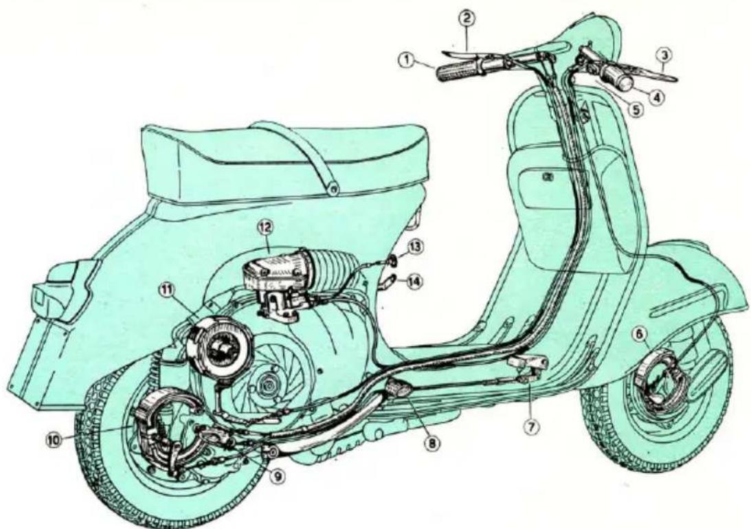
Technical diagram of a light green electric scooter with numbered parts for identificationFig. 4 - Installation of controls and transmission
Fig. 4 - Mandos y transmisiones
- Gear change twist grip - 2. Clutch control lever -
- Front brake lever - 4. Throttle control twist grip -
- Dip-switch with horn button - 6. Front brake shoes -
-
Rear brake pedal - 8. Kickstarter - 9. Gear change
selector - 10. Rear brake shoes - 11. Clutch - 12. Air
cleaner and carburettor - 13. Push pull rod of starter device - 14. Fuel cock. -
Mando cambio - 2. Palanca mando embrague
- Palanca freno delantero - 4. Puño mando gas -
Desviador luces con pulsador para claxon - 6. Morda
freno delantero - 7. Pedal freno trasero - 8. Pedal
arranque - 9. Selector cambio - 10. Mordazas freno
sero - 11. Embrague - 12. Carburador y filtro decente - Mando dispositivo « starter » - 14. Llave mezcla.
PERFORMANCE AND SPECIFICATIONS
Consumption (CUNA standards) 2.8 litres/100 Km (101 mls/imp gal. 85 mls/U.S. gal).
Max. speed with one up (CUNA standards) 100 Km/h (62 m.p.h.) with two up 85 Km/h (53 m.p.h.)
Carrying capacity Driver and passenger Radius of action 320 Km (200 mls.) Wheel base 1220 mm (48")
Overall handlebar width 710 mm (28") Overall length 1795 mm (70".7) Overall height 1045 mm (41".2)
Min footboard height 220 mm (8".7) Min turning circle 1400 mm (55")
Total weight, dry plus spare wheel 110 Kg. (242 lbs)
CARACTERISTICAS TECNICAS
text_image
Technical diagram of a vintage scooter with labeled parts including suspension, wheelbase, and gear assemblyFig. 5 - Installation of engine and suspension
- Group steering column and front suspension - 2. Engine - 3. Crankcase half clutch side with suspension arm 4. Rear suspension spring and damper assembly.
Fig. 6 - Sectional view of engine
text_image
Technical diagram of an electrical circuit with labeled components and wiring connectionsFig. 7 - Ignition diagram
Fig. 7 - Esquema del encendido
- Ignition coil in flywheel magneto - 2. External H.T. Coil - 3. Rotor cam - 4. Breaker - 5. Condenser - 6. Sparkplug - 7. Engine cut-out on switch.
- Bobina del volante magnético - 2. Bobina A.T. exterior - 3. Excéntrica rodante - 4. Ruptor - 5. Condensador - 6. Bujía - 7. Pulsador masa motor.
ENGINE
Single horizontal cylinder, two stroke engine with cross flow scavenging and flat top piston.
Bore . . . . . . mm. 58
Stroke . . . . . . mm. 60
Cylinder displacement. 158.53 cc.
Compression ratio . . 7.3 : 1
Engine installation (see fig. 5): the engine is hinged to the chassis by the swinging arm of the crankcase half clutch side and the oscillations thereof absorbed by the rear suspension. The driving wheel is secured to the extremity of the gear box out-put shaft.
The engine is protected laterally by a detachable cowl (see page 19 and fig. 17); the crankcase is equipped with a splash guard to protect it when the vehicle is running on wet and muddy roads.
Ignition - By means of H.T. external coil
MOTOR
We recommend the use of a good quality standard grade gasoline and to mix well with the oil.
with primary circuit fed by coil in the flywheel magneto (see fig. 7).
Sparking plug: Marelli CW 250 L-T, CW 240 G or CW 240 B; Champion NA 8; Bosch W 240 T 2; K. L.G. Fe 80 and Lodge 2 HLN.
Spark advance of 26^ ± 1^ .
Lubrication: the piston-cylinder, wrist pin-con-rod-crankshaft are lubricated by the oil in the fuel mixture.
The clutch, gear box transmission and main bearing clutch side, are lubricated by the oil content of the gear box. See page 50 for lubrication of main bearing, flywheel side.
Fuel feed: by gravity (see fig. 8). Fuel tank capacity 9 l. (1.98 imp. gals.) with a reserve of approx. 1.8 l. (0.39 imp. gals.)
text_image
Technical schematic diagram of a mechanical device with numbered components and fluid flow pathsFig. 8 - Fuel feed distribution diag. — Fig. 8 - Esquema de alimentación 1. Three way cock (A: Reserve; B: Open; C: Closed) - 2. Air cleaner - 3. Air corrector jet - 4. Slow running jet - 5. Air calibrator to idling jet - 6. Throttle slide set screw - 7. Air calibrator to starter jet - 8. Starter jet - 9. Starter valve - 10. Throttle slide - 11. Intake port - 12. Slow running adjuster screw - 13. Main jet - 14. Mixer - 15. Float and chamber - 16. Cylinder transfer ports - 17. Piston transfer port - 18. Exhaust duct. 19. Fuel exhaust pipe.
natural_image
Technical line drawing of a mechanical assembly with internal components (no text or symbols)Fig. 9 - Cooling circuit
Fig. 9 - Circuito de enfriamiento
Three way cock (closed, open, reserve) and sediment bowl.
Carburettor - Type Dell'Orto SI 27/23, with jets located forward to the throttle slide valve and including an incorporated unit for cold starting.
Cooling: At all speeds by a centrifugal fan (see fig. 9).
Transmission: Direct rear wheel transmission through, clutch, spring gear and gear box.
Clutch: Multiplate with friction lined driving discs. The unit is controlled by a clutch lever on left hand handlebar, adjustable through bowden cable transmission.
Gear box: Four speed mesh gears. This unit is operated by a twist grip, which acts in
scooterhelp.com
Caution: We recommend that the muffler and air intake be kept in perfect working efficiency and that they are not altered in anyway whatsoever; this will avoid deleterious noise and hence possible infringement to the laws governing noise.
unison with the clutch lever, situated on the extremity of the left hand handlebar.
Engine - wheel transmission ratio
| 1st Gear | 14.72 : 1 |
| 2nd Gear | 10.28 : 1 |
| 3rd Gear | 7.61 : 1 |
| 4th Gear | 5.84 : 1 |
Starting: Kickstarter on R. H. rear side of vehicle, which when operated acts on gear box cluster.
Exhaust muffler - Combined expansion absorption type.
Air intake - Inside bodywork. Ample induction pipe, silencing bellows and air filter.
Frame - Heavy gauge pressed sheet steel of monocoque type structure, electrically welded and designed to give excellent protection to both driver and passenger. The front mudguard and the two lateral detachable cowls complete the frame in its protective capacity.
Handlebar housing: Pressure die cast in light alloy with incorporated speedometer housing. All the control cables and electrical wiring to the handlebars are completely sealed in said group.
Steering column - Suspension - Wheels: The handlebars are clamped to the upper extremity of the steering column; on the lower extremity is pivoted the oscillating
CHASIS - SUSPENSIONES - RUEDAS
natural_image
Technical illustration of a mechanical component with a pointed tip and clamped parts, showing no text or symbols.N. B. - For releasing the saddle push the button indicated by the arrow in the diag.
wheel hub. Trailing link front suspension with double acting hydraulic damper and variable rate coil return spring. Pivoting engine at rear with variable rate coil spring and double acting hydraulic damper (see fig. 5).
The wheels are interchangeable and are made up of flanges in heavy gauge pressed steel sheet. They are secured to the pressure die cast brake drums by means of five studs and nuts.
Tyres are of 3.50 x 10".
Saddle - Dual purpose: ie. permits the driver to travel laying flat across the vehicle, or both driver and passenger in a normal sitting position. Extremely comfortable pleasing and streamlined. It is pivoted on its forward edge for accessibility to the fuel tank cap (see fig. 10).
Brakes - Expanding type with cable transmission: the front brake is operated by the lever on R. H. handlebar, the rear one is
scooterhelp.com
text_image
Technical diagram illustrating mechanical assembly steps with labeled parts and cross-sectional viewsFig. 11 - Steering lock.
Fig. 11 - Dispositivo anti - hurto
1. Normal position - 2. Locked position.
1. Posición normal - 2. Posición de cierre.
operated by a pedal on the R. H. floorboard (which through an apposite micro stop switch contemporaneously actions the rear lamp braking or stop bulb).
The brake drums in light alloy, to which are secured the wheels, are internally lined with cast iron and externally equipped with cooling fins.
Rear brake jaws are independently pivoted.
Stand - Twin legged device applied under the footboard. When the vehicle is running said stand is held firmly against the footboard by a strong return spring.
Steering lock - Installed in the frame below the handlebars. To lock the vehicle it is necessary turn the handlebars in an anticlockwise direction to the end of its run and rotate the key through approx 180°: only when the group is locked can said key be extracted. For unlocking rotate the key in opposite direction and bring handlebars to normal position (see fig. 11). sero mediante el pedal, (sobre el estribo derecho) que actúa a través de un dispositivo (interruptor luz de parada), sobre la señal luminosa aplicada en el piloto.
Under no conditions should the steering lock be oiled. Avoid starting up the engine if the key is not inserted and does not remain in the lock.
Speedometer. Lodged in handlebar housing (see fig. 11). It is driven by a gear on the front wheel through a flex cable installed inside the vehicle chassis.
During night riding the speedometer dial is illuminated by an apposite bulb.
Spare wheel: furnished as standard equipment to the vehicle and housed inside the left hand cowl. On the undersurface, the wheel is protected from mud, rain etc., by a sheet metal pressing. For removing or replacing the spare wheel in its housing, proceed according to instructions at page 37. No engrasar el dispositivo anti-hurto tampoco en caso de defectuoso funcionamiento. Evitar absolutamente de poner en marcha el motor si la llave no está en el dispositivo y no queda allí empeñada.
Fig. 12 - Layout of vehicles electrical plant
1 - 2: H. T. coil terminal - 3. Black - 4: Yellow - 5: Green 6: Red - 7: White - 8: Pink - 9: Violet - 10: Brown - 11: Sky - blue.
1: Pilot light and tail lamp on
2: Head light tail lamp and speedometer light on
A: Dip switch
B: Horn button
M: Engine cut - out.
0: Luces apagadas
A six-pole flywheel magneto (nominal voltage: 6V) supplies alternating current to the following groups:
— The 115 mm dia. (4."52) head lamp installed on the handlebars, is provided with a 25/25 W double filament bulb (main and dipped beam) and a 5 W bulb for pilot light inside the reflector.
— The tail lamp with red transparent glass and reflector has a 5 W bulb which also illuminates the licence plate and a 10 W bulb for the stop light.
Speedometer illuminating lamp 6V - 0.6 W.
— Horn
The light and dip switch unit with two levers is installed on the right hand side of the handlebars (see Fig. 14)
scooterhelp.com
INSTALACION ELECTRICA
The speedometer is illuminated by an apposite bulb.
Two open ended box wrenches of 11-14 mm. and 17-21-22 mm. respectively. 1 tommy bar for box wrenches. 1 double open ended wrench (11-14 mm.) and three single open ended wrenches (7-8-10). 1 Screwdriver. The standard tool kit is contained in a canvas roll together with this booklet and test sheet in the apposite box which has a security lock.
ACCESSORIES
Clients should request information from their local dealers.
Because of the simple and rational concept, the Vespa is extremely easy to handle and at the same time does not require a specialised knowledge for its maintenance. The only requirements necessary are standard tools and some essential instructions.
Running - in: Instruction for the first 3000 Km. (1800 mls):
| Distance Km or mls. | Bottom gear | 2 nd gear | 3 rd. gear | Top gear |
| Up to 2000 Km (1200 mls)From 2000 to 3000 Km.(1200 to 1800 mls) | Km/h2515 mph | Km/h4025 mph | Km/h5534 mph | Km/h7044 mphKm/h8050 mph |
Do not maintain these max. permissible speeds over long distances. Uphill runs should not be taken at full throttle.
— Change the oil in gear box after the first 1000 Km (600 mls) and check that all nuts and bolts are tight.
Mixture to use both during and after running-in should be gasoline and oil at 5%. Use pure mineral oil ESSO SAE 30 or Shell X - 100 Motor Oil 2 T and a standard grade gasoline ( 12 pint per 114 gall.).
NORMAS PARA EL USO
text_image
Technical diagram of a scooter with labeled parts including battery, wheel, and seat componentsFig. 15 - Operations for starting up vehicle
A. Open fuel cock; see the three positions in fig. 8 - B. Place the gear in neutral - C. Action the push pull rod of the starter device (if the engine is cold) - D. Hold the throttle control closed - E. Action kickstarter.
Caution: always keep the breather on the fuel cap clean.
TYRE PRESSURES
| Tyres | With one up | With 2 up |
| Front | 1.2 Kg/cm^2 (17 p. s. l.) | 1.2 Kg/cm^2 (17 p. s. l.) |
| Rear | 1.75 Kg/cm^2 (25 p. s. l.) | 2.5 Kg/cm^2 (35.5 p. s. l.) |
PRELIMINARY CHECKS BEFORE RUNNING
— Check that the oil level comes up to the inspection hole in gear case (see plug marked « OLIO » fig. 23).
This should be controlled with the vehicle propped up on its centre stand on a flat surface.
STARTING UP: carry out the operations indicated at fig. 15.
Note: For starting with a cold engine, action « starter » push pull rod, (rod C fig. 15) and keep the throttle control twist grip closed: under these conditions the starter device will functiona at maximum efficiency.
Do not use the starter device with a warm engine.
N. B. - Once the engine is ticking over regularly, bring the rod « C » to the closed position so as to avoid an over rich carburation with consequent loss in performance, higher consumption ect.
In cases where the carburettor is flooded and starting is rendered difficult the vehicle can be « push started » (engage the 2nd gear, release the clutch, push the vehicle to a suitable speed, and quickly let in the clutch and release as soon as the engine is firing regularly).
text_image
Technical diagram of a vehicle's front wheel assembly with numbered components and labeled partsFig. 16 - Layout of gear box and transmission
Fig. 16 - Esquema del cambio
- Gear change twist grip - 2. Clutch lever - 3. Gear change cables - 4. Gear selector quadrant - 5. Selector spindle - 6. Selector spider - 7. Bottom gear - 8. 2nd gear - 9. 3rd gear - 10. Top gear - 11. Drive shaft - 12. Spring gear - 13. Clutch.
N. B. - The position 1-2-3-4 on the gear change twist grip correspond respectively to bottom 2nd - 3rd and top gear: the «0» indicates neutral.
text_image
Technical diagram of a helmet assembly with numbered parts for identificationFig. 17 - Detaching engine cowl
Fig. 17 - Desmontaje cofre motor
- Cowl locking lever - 2. Forward locating pin - 3. Spring clip for securing cowl to frame - 4. Rear hooked pin of cowl.
- Palanca de cierre cofre - 2. Perno delantero cofre - 3. Gancho fijación cofre a la carrocería - 4. Perno curvo posterior del cofre.
the engine a few times; after said operation insert sparkplug and carry out normal starting procedure.
For access to the engine remove the cowl as follows:
— Pull out the locking lever (1) and rotate so as to release it from the cowl. Swing the cowl slightly outwards so that the forward locating pin 2) is free of its housing in the frame.
— Now swing the cowl upwards about the rear hooked pin (as indicated by the path traced in dotted lines on fig. 17): thus releasing the spring clip 3) from its relative support.
— Rotate the cowl outwards about the curved pin 4) to release it from the frame and thus detaching it from the vehicle itself.
For re-assembling repeat an analog reverse procedure.
In the case of irregular functioning of the gear box or stiffness in the gear change control, we recommend that adjustments be carried out by appointed retailers or authorized Service Stations.
SETTING THE VEHICLE IN MOTION. With the engine at slow running revs. release the clutch, twist the gear change grip so that figure « 1 » is aligned with the incision on the handlebar housing (see fig. 16) then gently let in the clutch and contemporaneously open the throttle.
Changing gear. On attaining the required speed in bottom gear, close the throttle, release the clutch and bring the gear change grip in the position 2. Then let in the clutch and open the throttle. For 3rd and top gear carry out the same procedure. The same method applies for changing down. On reducing speed, do not hesitate in changing down. See gear box, transmission layout on fig. 16.
control, we recommend that adjustments be carried out by appointed retailers or authorized Service Stations.
For cutting out the engine push the cut-out button.
WHEEL AND TYRE CHANGE
By regulating the tyre pressure to those indicated at pag. 31 the wheels can be interchanged at will. When a flat tyre is to be changed, release the five nuts securing it to the brake drum and pull of sideways; then repair or substitute with the spare wheel.
Operations for removing the spare wheel - Remove L. H. cowl as indicated on instructions at fig. 17. Unscrew the lower of the three bolts securing the spare wheel to the chassis (L. H. side). Said operation will contemporaneously release the spare wheel protective pressing. Now unscrew the reendurecimiento al maniobrar, aconsejamos al usuario recurrir para el ajuste a un Taller autorizado.
natural_image
Technical illustration of a mechanical bearing assembly showing three views of the wheel (no text or labels)Fig. 18 - Dismantling tyre
Fig. 18 - Desmontaje neumático
maining two nuts to free the wheel (fig. 19). Repeat a reverse procedure for assy. For dismantling the wheels, deflate the tyre, unscrew the flange retainer nuts and remove relative washers; the two flanges are now free to be seperated, giving access to tyre and inner tube (see fig. 18).
Brake adjustment - The brakes are correctly adjusted if:
— the wheels rotate freely when respective pedal and brake lever are in their resting positions.
— The braking action starts immediately on operating respective controls.
Said conditions are obtained by adjusting the respective set screw indicated by arrow on fig. 20.
Slow running adjustment - Act on the throttle slide stop screw (n. 6 fig. 8), for opening out screw in, for closing unscrew.
scooterhelp.com
natural_image
Technical illustration of a car wheel assembly with visible tire and mounting bracket (no text or symbols)natural_image
Mechanical assembly diagram showing a car brake system with no visible text or symbolsFig. 20 - Brake adjustments
Fig. 20 - Ajuste frenos
The screw (n. 12 fig. 8) regulates the flow of carburated air from slow running jet: by respectively screwing in or out, a minor or major flow of carburated air from the jet is obtained, thus influencing the functionally of the engine, at low revs.
However, in the case of adjustments, we recommend that said operation be carried out by an authorized Service Station.
Note - The carburettor body is mounted with an adjuster screw (see fig. 8) for regulating the throttle cable play. This screw should only be readjusted on dismantling and reassembly or in cases of absolute necessity. However, we strongly recommend that said operation be carried out by an authorized Service Station.
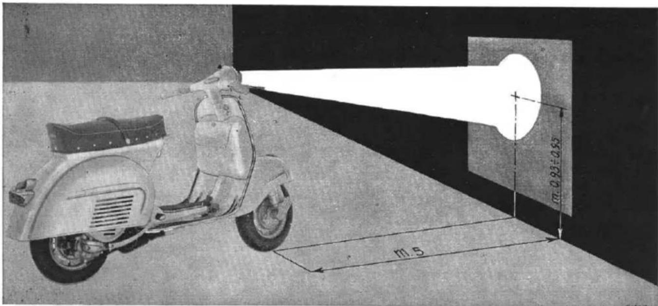
SETTING THE HEADLAMP BEAM
A correct orientation can be obtained by acting on the three screws which secure the headlamp in its housing.
scooterhelp.com
Ensure that the spring washers are in position when re-assembling the wheel: tighten the nuts diagonally and progressively.
Before carrying out said operation place the vehicle in front of a white screen as indicated in fig. 21 and check that the front Comprobar que los neumáticos delantero y trasero estén inflados respectivamente a 1,2 y 2,5 kg/cm².
text_image
m.93±0.85 m.5Fig. 21 - Headlamp adjustment
The height of the point «+» is constant for solo or driver and pillion passenger adjustment.
and rear tyres are inflated at 1,2 and 2,5 Kg/cm² (17 and 35.5 p.s.i.).
Check oil level in gear case (see page 31).
Every 4000 Km. (2400 mls).
1) Change oil in gear case. (The oil will run more easily when warm immediately after a run). Introduce a small quantity of flushing oil, run the engine a few minutes, to ensure thorough circulation and cleasing, and drain off through draining hole (fig. 23). Afterwards refill gear case up to inspection hole (about 250 grms). Carefully clean the magnetic plug on oil draining hole.
N. B. - The oil should be changed also after the first 1000 Km. (600 mls.) (see pag. 29).
2) Remove air filter and agitate in 30% oil-gasoline bath.
ENTRETENIMIENTO
Cada 2.000 km.
3) Clean and refill the front wheel hub through apposite grease nipple, lubricate clutch and brake levers.
4) Clean sparking plug electrodes using fine emery cloth or file and set the spark gap at 0.6 mm (0".023). Check the sparking plug insulation; if cracked or broken substitute plug. Clean in neat gasoline.
Using a suitable type sparking plug will prevent the possibility of many engine defects.
N. B. - The following operations 5-6 and 1-2 of the successive paragraph should be carried out at an authorized Service Station.
5) Decoke muffler and engine as follows: dismantle muffler, engine cooling cowl, cylinder head and barrel. Ensure that the cylinder is free of carbon deposits. De-
text_image
0.3-0.5mmFig. 22 - Registration of contact breaker points Fig. 22 - Ajuste platinos del ruptor
coke the muffler exhaust pipe using a hoo- ked steel wire or by blowing through com- pressed air after having previously heated. During this operation it is considered advi- sable to keep the exhaust pipe facing down- wards.
6) Grease the felt pad which lubricates the flywheel magneto cam (see fig. 22, for dismantling fan).
Every 8000 Km. (4800 mls.):
1) Clean the contact breaker points (removing the fan as indicated in fig. 22) and adjust gap between the limits of 0.3 and 0.5 mm (0".011 and 0".019).
2) Lubricate all control cables.
NOTE
a) In the case of engine overhauls dismantle the rubber oil seal, flywheel side (this operation can be carried out without dismantling the engine). Flush out existing
We recommend that plugs prescribed in this booklet be mounted.
grease from bearing housing with gasoline and then refill with about 6 cc. of fresh grease ESSO MULTI-PURPOSE GREASE 2. or SHELL ALVANIA 3. Having completed the above mentioned operation re-assemble a new oil seal and then check engine timing.
b) In the case of overhauls to front suspension, lubricate the wheel support bearing, of the speedometer drive gear, with ESSO MULTI - PURPOSE GREASE H or Shell Retinax A.
CLEANING VEHICLE
For cleaning down engine, brush on paraffin and dry off with a clean rag. All painted parts should be sponged down with water and dried off with chamois leather. Do not use paraffin for cleaning paintwork as it will cause it o deteriorate and become dull.
The reflector should be cleaned using an air jet or soft feather. Do not wipe down with a cloth or contact with fingers as it will eventually render the reflector opaque.
Laying up - We recommend the following procedure:
1) Clean the vehicle.
2) With the throttle control twist grip fully open, introduce about 40 cc. of ESSO MOTOR OIL 30, Shell X - 100 Motor Oil 2 T. or Shell X - 100 Motor Oil 30 into the car-rettor, through the apposite plugged hole on the air cleaner. After introducing the oil, kick over the engine three or four times.
3) Raise the vehicles wheels off the ground by placing chocks under the footrest.
4) Drain off tank and carburettor.
5) Coat all unpainted metallic parts with anti-rust grease.
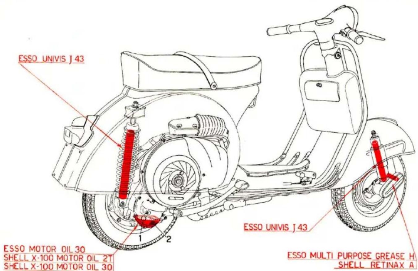
N. B. - Front and rear dampers are charged with ESSO UNIVIS J 43.
N. B. - Amortiguadores del. y tras. cargados con. ESSO UNIVIS J 43.
scooterhelp.com
text_image
ESSO UNIVIS J 43 ESSO MOTOR OIL 30 SHELL X-100 MOTOR OIL 2T SHELL X-100 MOTOR OIL 30 ESSO UNIVIS J 43 ESSO MULTI PURPOSE GREASE H SHELL RETINAX AFig. 23 - Lubrication scheme
Fig. 23 - Esquema del engrase
A: Engine lubricated by 5% oil in mixture - 1. Oil filler screw - 2. Oil draining screw.
When the vehicle is not functioning regularly carry out the controls and relative remedies as indicated on the following table.
In a case where the fault persists, after having attempted to remidy, we recommend that the vehicle be serviced by an authorized Station where special tooling is at disposition for all necessary overhauls.
| Fault finding | Remidy |
| HARD STARTING1. - Fuel feed - CarburationFuel run outFilter, jets, carburettor housing or tap blocked or dirtyEngine flooded - Air cleaner blocked or dirty2. - IgnitionSparkplug dirty-insulation crackedContact breaker points worn pitted, dirty, or badly registeredMISCELANEOUS FUNCTIONAL IRREGULARITIES1. - Low performanceMuffler carbonizedPlug not fully screwed in | Set tap to reserve and refuel at next filling station.Dismantle and clean in gasoline. Dry using an air jet.See pages 32-44.Disconnect spark plug lead, bring terminal to earth, action kickstarter and check for regular sparking.See pages 12-45.This operation should be entrusted to your usual dealer who will clean, change or set the points according to the conditions.De-coke (see pag. 45).Tighten with 21 mm wrench |
scooferhelp.com
| Fault finding | Remidy |
| 2. - Backfiring3. - Excessive consumptiona) Air cleaner blocked dirty, « starter » device open or blocked.b) Other causes (carburettor, lack of compression etc).4. - Noisy engine - faulty clutch - gears slipping out of mesh of own accord - kickstarter group not engaging - controls and steering defective - inefficient suspension5. - Inefficient brakingExeccise stroke of lever or pedalLinings worn: impregnated with oilBrake linings scratched6. - Inefficient electrical plantWire terminals disconnected or incorrectly hooked up Inaccurate headlight beam setting | Check sparking plug: clean, substitute or adjust electrode gap (see pag. 45).Clean filter in gasoline and dry with air jet then dip in 30% gasoline oil bath.Release starter device push pull rod and lubricate.Entrust repair to your local dealerEntrust repairs to an authorized dealer or Service Station.Adjust (see fig. 20).Substitute; wash in gasoline and dry at room temperatureConsult your local dealer about the oil losses.SubstituteRe-connect properly (see figs. 12 and 13).Correctly set. See page 40). |
| NOTICE - In the case of the front pilot light burning out with consequent burning out of the rear light and vice versa; it is therefore necessary before switching on again that both these bulbs be substituted contemporaneously.- For a correct and efficient repair to the electrical plant, the wiring diagram illustrated in this booklet should always be consulted (plus relative notes). | |