
WN-200HD - Security Camera AIRLIVE - Free user manual and instructions
Find the device manual for free WN-200HD AIRLIVE in PDF.


User questions about WN-200HD AIRLIVE
0 question about this device. Answer the ones you know or ask your own.
Ask a new question about this device
Download the instructions for your Security Camera in PDF format for free! Find your manual WN-200HD - AIRLIVE and take your electronic device back in hand. On this page are published all the documents necessary for the use of your device. WN-200HD by AIRLIVE.
USER MANUAL WN-200HD AIRLIVE
Powered by OvisLink Corp.
Copyright & Disclaimer
No part of this publication may be reproduced in any form or by any means, whether electronic, mechanical, photocopying, or recording without the written consent of OvisLink Corp.
OvisLink Corp. has made the best effort to ensure the accuracy of the information in this user's guide. However, we are not liable for the inaccuracies or errors in this guide. Please use with caution. All information is subject to change without notice
This product contains some codes from GPL. In compliance with GPL agreement, AirLive will publish the GPL codes on our website. Please go to www.airlive.com and go to the "Support->GPL" menu to download source code.
All Trademarks are properties of their respective holders.
FCC Statement
Federal Communication Commission Interference Statement This equipment has been tested and found to comply with the limits for a Class B digital device, pursuant to Part 15 of the FCC Rules.
These limits are designed to provide reasonable protection against harmful interference in a residential installation. This equipment generates, uses and can radiate radio frequency energy and, if not installed and used in accordance with the instructions, may cause harmful interference to radio communications. However, there is no guarantee that interference will not occur in a particular installation. If this equipment does cause harmful interference to radio or television reception, which can be determined by turning the equipment off and on, the user is encouraged to try to correct the interference by one of the following measures:
● Reorient or relocate the receiving antenna.
- Increase the separation between the equipment and receiver.
- Connect the equipment into an outlet on a circuit different from that to which the receiver is connected.
- Consult the dealer or an experienced radio/TV technician for help.
FCC Caution
Any changes or modifications not expressly approved by the party responsible for compliance could void the user's authority to operate this equipment.
This device complies with Part 15 of the FCC Rules. Operation is subject to the following two conditions: (1) This device may not cause harmful interference, and (2) this device must accept any interference received, including interference that may cause undesired operation. For product available in the USA/Canada market, only channel 1\~11 can be operated. Selection of other channels is not possible.
This device and its antenna(s) must not be co-located or operation in conjunction with any other antenna or transmitter.
IMPORTANT NOTE
FCC Radiation Exposure Statement:
This equipment complies with FCC radiation exposure limits set forth for an uncontrolled environment. This equipment should be installed and operated with minimum distance 20cm between the radiator & your body.
Table of Contents
1. Introduction......1
1.1 Overview....1
1.2 Features....2
1.3 System Requirements....2
1.4 Package Contents....3
1.5 Physical Description....3
1.5.1 Front View ....3
1.5.2 Bottom View 4
1.6 Hardware Installation....6
2. Getting Started 8
2.1 IP Wizard....8
2.1.1 View....10
2.1.2 LAN 10
2.1.3 Wireless....13
2.2 UPnP for Windows....16
2.3 Install the IP Camera behind NAT router....17
2.4 Configure IP Camera via Web UI....18
2.4.1 Login as User 19
2.4.2 Login as Administrator....20
3. Configure the Camera....21
3.1 Monitor the Image Section 21
3.2 View Profile 21
3.3 Streaming Protocol....21
3.4 Language 21
3.5 Two-Way Audio....21
3.6 Full Screen....22
3.7 Active Control....22
3.7.1 Digital Zoom 23
3.7.2 Snapshot 23
3.7.3 Record....24
3.7.4 Volume 25
3.7.5 About 25
4. Monitor the Image Section 27
4.1 Monitor the Image Section 27
4.2 Configure via Web UI 27
4.2.1 Network 27
4.2.2 Wireless....29
4.2.3 DDNS 33
4.2.4 PPPoE....35
4.2.5 Steaming 37
4.2.6 UPnP 38
4.2.7 Bonjour 39
4.2.8 IP Filter 40
4.2.9 IP Notification 41
4.3 Camera – Adjust Camera Parameters ....43
4.3.1 Picture 43
4.3.2 Privacy Mask 45
4.4 System – Configure and Maintain .... 46
4.4.1 System 46
4.4.2 Date & Time....48
4.4.3 Maintenance....49
4.5 Video-Configure Profile 51
4.5.1 Common....52
4.5.2 Video Profile....53
4.5.3 ROI 54
4.6 Audio – Audio Parameters ....55
4.6.1 Setting 55
4.6.2 Manage User Name, Password and Login Privilege .....56
4.6.3 E-Mail 57
4.6.4 Object Detection....58
4.6.5 Storage – Status and Configuration of SD card....60
4.6.6 Recording List- Files List inside SD Card 61
4.6.7 Event Sever....61
4.6.8 Event Schedule 66
- Troubleshooting & FAQ....72
5.1 Monitor the Image Section 72
5.2 PING 78
5.3 Bandwidth Estimation....79
5.4 Specification Table....80
5.5 Configure Port Forwarding Manually....82
5.6 DDNS....85
5.7 Power Line Frequency 92
5.8 3GPP Table....94
5.9 UPnP....95
1
Introduction
natural_image
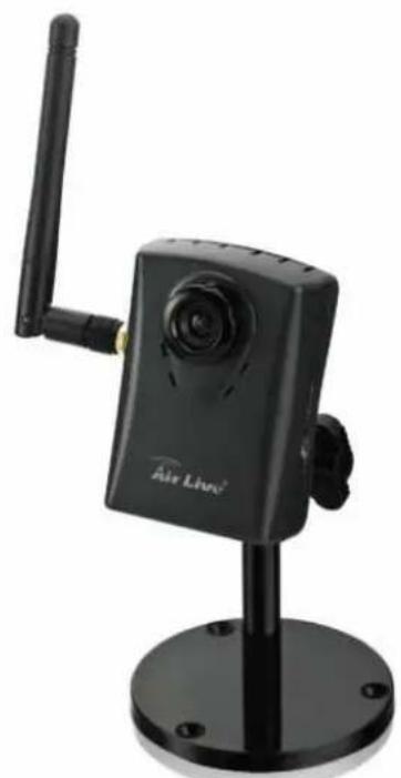
Black Air Live digital camera with antenna and mounted base (no visible text or symbols)WN-200HD
1.1 Overview
This camera is an inexpensive and fully scalable surveillance device. Because the Network Cameras can be plugged into your existing local area network (LAN), you will potentially save thousands of dollars from unnecessary cabling. The device is accessible via the LAN or Internet connection. Connect your device directly to a local area network or xDSL modem, and with Microsoft® Internet Explorer you get instant, on demand video streams. Within minutes you can set up the device to capture a video sequence to a PC. The live video can be uploaded to a website for the world to see.
1.2 Features
● Easy installation with setup wizard (IP Wizard II)
- UPnP device discovery and NAT router transversal for easy installation
● Dynamic IP Service, DIPS®, to search your IP camera from Internet easily
● H.264, MPEG4 and JPEG triple compression simultaneously
● 2 Mega-pixel resolution
- Up to 9-profile encoder simultaneously
● 2 Mega-pixel or 720P mode selectable
- Up to 30 fps for 720P mode
● Up to 15 fps for 2 Mega-pixel mode
- UDP / TCP / HTTP protocols selectable
- IEEE 802.11n wireless LAN
● WEP/WPA/WPA2-PSK wireless security
● 3GPP for 3G mobile remote application
- Digital zoom
● Built-in microphone
● Audio line out
- Two-way audio
● Intelligent motion detection up to 10 zones
- Go to preset once motion triggered
● Image transmission using an FTP or e-mail for event
- DDNS and PPPoE
● Multi-channel control software for surveillance application
- On-line firmware upgrade
1.3 System Requirements
● Microsoft Internet Explorer 6.0 or later
● Microsoft Media Player 11.0 or later (to playback recorded file)
● VGA Monitor resolution 1280 x 1024 or higher
● Pentium-4 3.6 GHz or higher
● Memory Size: 1GB or more
● Windows XP, Vista, 7
1.4 Package Contents
User can find the following items in the package:
● This camera is the main element of the product.
- Camera Stand with screws
- Detachable WLAN antenna
● Power adapter dedicates 12V DC electric power output to Network Camera.
- User's manual CD provides important information and instructions for operating the Network Camera.
- Quick start guide provides important information and instructions for installing this device.
If any of the above items are missing, please contact your dealer immediately.
Note: Using a power supply with a different voltage than the one included with the Network Camera will cause damage and void the warranty for this product.
1.5 Physical Description
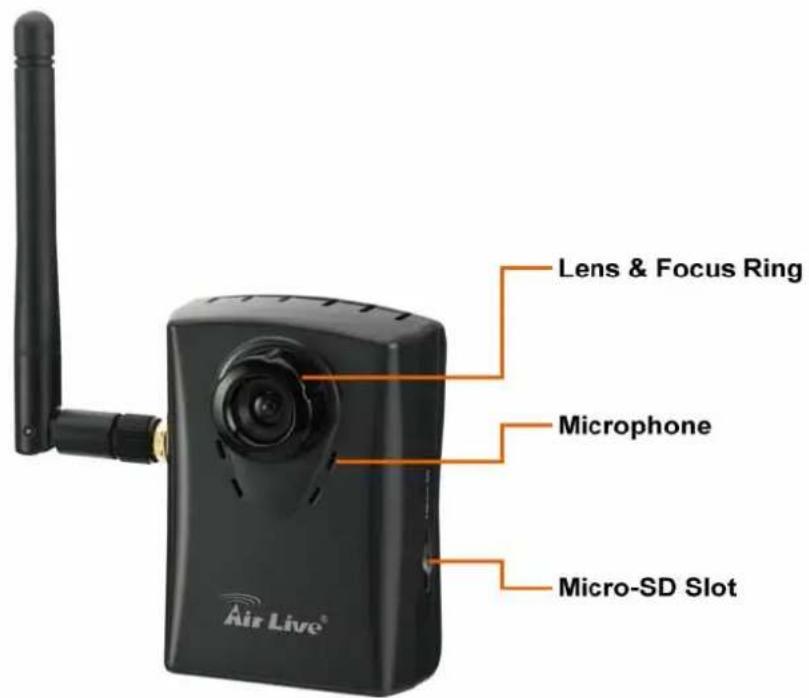
1.5.1 Front View
text_image
Lens & Focus Ring Microphone Micro-SD Slot Air Live®1. Lens & Focus Ring
User could use this ring to adjust focus manually.
2. Microphone
The Camera has built-in an internal microphone. This microphone is hidden in the pinhole located on the front panel.
3. Micro SD Card Slot
User can insert a micro SD card into this slot for event recording.
1.5.2 Bottom View
text_image
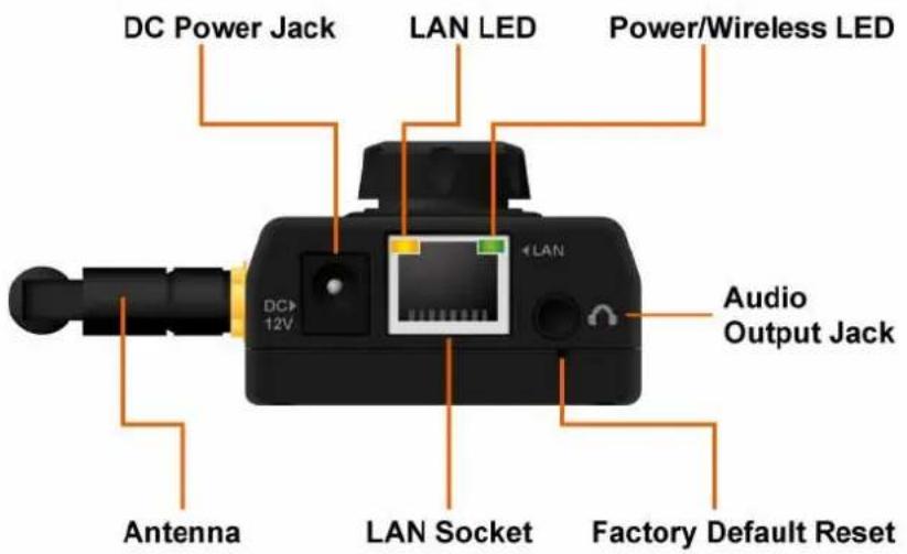
DC Power Jack LAN LED Power/Wireless LED DC 12V LAN Audio Output Jack Antenna LAN Socket Factory Default Reset1. Audio Output Jack
Audio-out Jack allows this device to output audio or alerting sound.
2. DC Power Jack
The input power is 12VDC.
Note that supply the power to the Camera with the power adapter included in package. Otherwise, the improper power adapter may damage the unit and result in danger.
3. Antenna
User can attach the included antenna to antenna connector (SMA type) or use another high-gain antenna to get higher performance.
4. Factory Default Reset
This button is hidden in the pinhole. This button is used to restore the all factory default settings. Sometimes restarting the camera will make the system back to a normal state. If the system still got problems after restart, user can restore the factory default settings and install it again. To restore the device, please follow the steps below:
(1) Insert the paper clip or other tool and press and hold the button down continuously.
(2) Hold it at least 5 seconds and release the tool. Then the device has been restored to default settings and reboot again.
Note: Restoring the factory default setting will lose the all previous settings included IP address forever. User needs to run the IPWizard II program to search the device and configure it to let the device work properly again.
5. LAN Socket
The LAN socket is a RJ-45 connector for connections to 10Base-T Ethernet or 100Base-TX Fast Ethernet cabling. This Ethernet port built N-Way protocol can detect or negotiate the transmission speed of the network automatically. Please use Category 5 cable to connect the Network Camera to a 100Mbps Fast Ethernet network switch or hub.
6. LAN LED (green color)
This LED will be flashing while network accessing via Ethernet.
7. Power / Wireless LED (orange color)
This LED is used to indicate whether DC power is on or not. In addition, this LED will be flashing while the wireless accessing of the Camera.
1.6 Hardware Installation
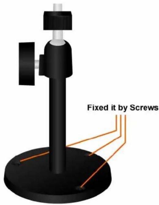
- Attach the Camera with the included stand
- Place the Camera on the table or fix it onto ceiling or wall
Use three screws to fix the Network Camera onto the ceiling or wall. You could also put the Network Camera on the table directly.
text_image
Fixed it by Screws3. Plug an Ethernet cable into the Camera
Connect an Ethernet cable to the LAN socket located on the Network Camera's bottom and attach it to the network.

text_image
DC 12V LAN Ethernet Cable- Connect the external power supply to Camera Connect the attached power adapter to the DC power jack of the Network Camera.
Note: Use the power adapter, 12VDC, included in the package and connect it to wall outlet for AC power.
2
Getting Started
2.1 IP Wizard
text_image
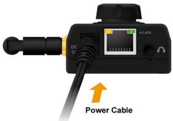
DC 12 4 LAN Power CableOnce you have installed the Network Camera well and powered it on, the network accessing type LED will turn on. It means the system is booting up successfully. Furthermore, if you have a proper network connection, and access to the Network Camera, the LED will flash green under wired mode or orange under wireless mode.
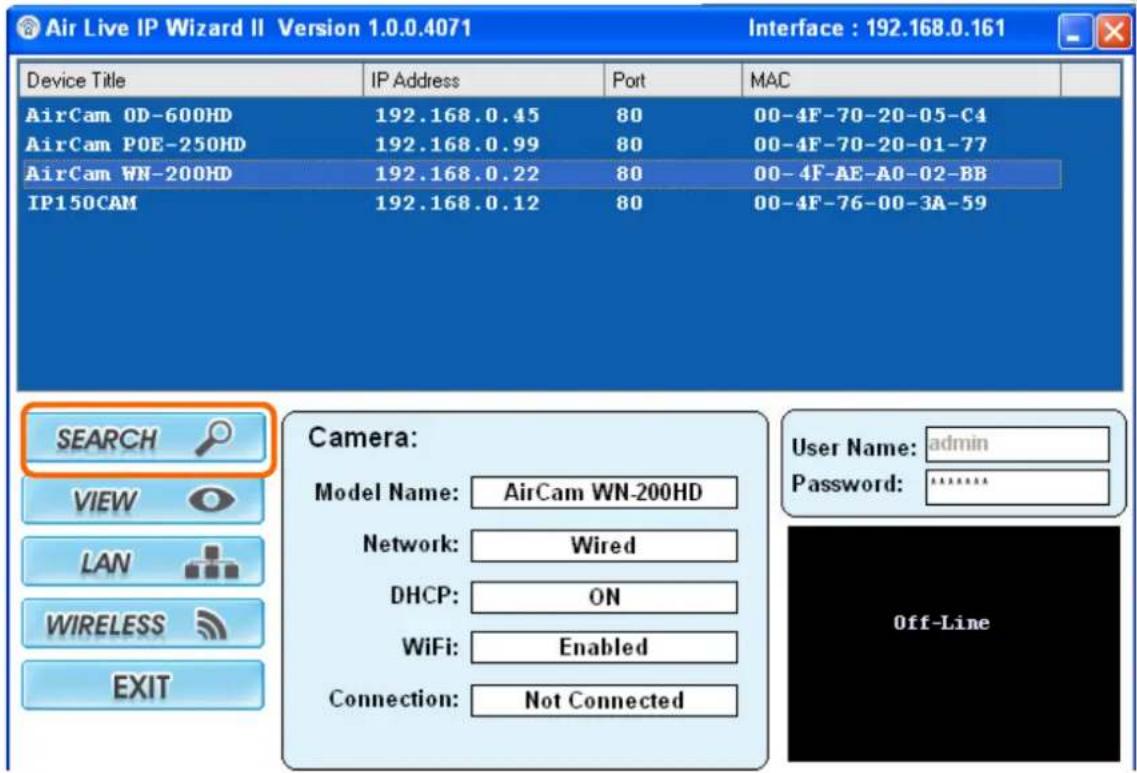
When you installed the Camera on a LAN environment, you have two easy ways to search your Cameras by IPWizard II or UPnP™ discovery. Here is the way to execute IPWizard II to discover Camera's IP address and set up related parameter in a Camera.
text_image
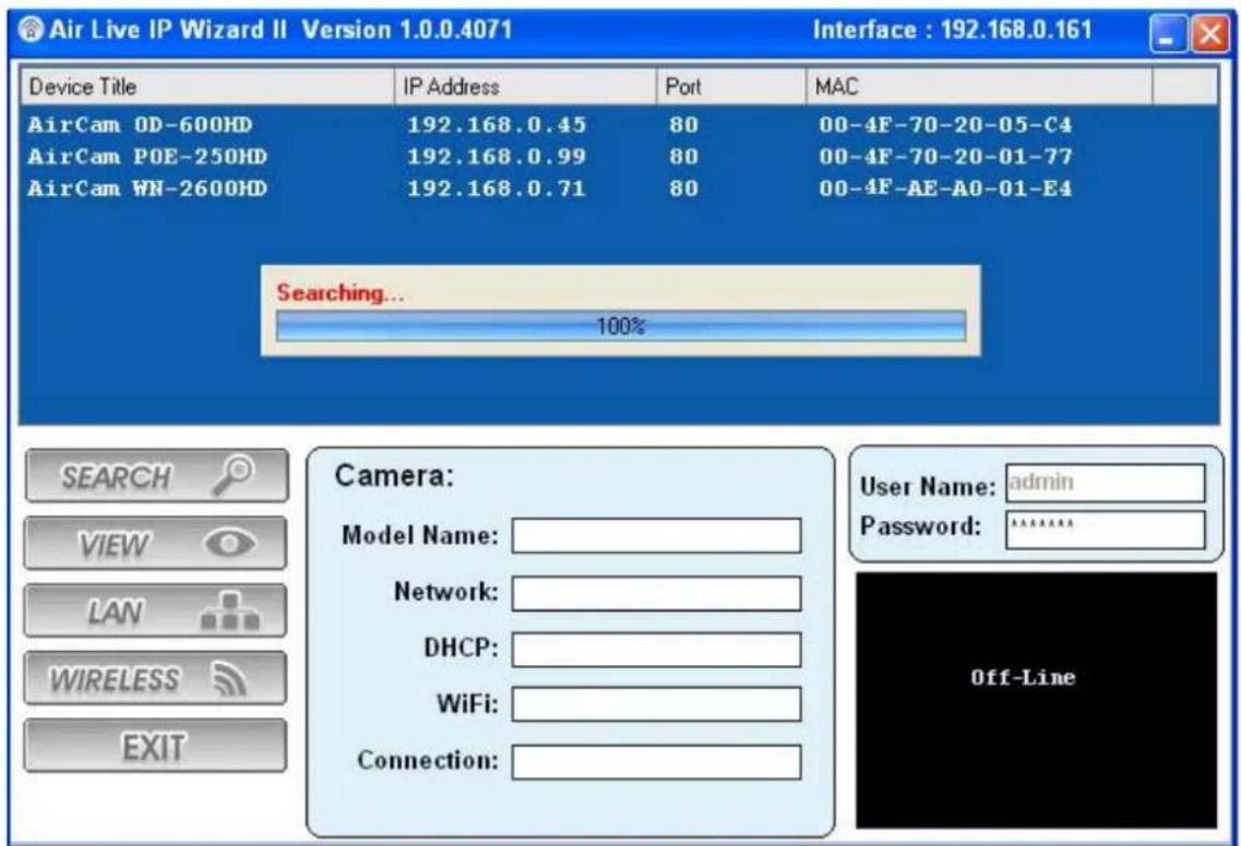
Air Live IP Wizard II Version 1.0.0.4071 Interface : 192.168.0.161 Device Title IP Address Port MAC AirCam OD-600HD 192.168.0.45 80 00-4F-70-20-05-C4 AirCam POE-250HD 192.168.0.99 80 00-4F-70-20-01-77 AirCam WN-200HD 192.168.0.22 80 00-4F-AE-AO-02-BB IP150CAM 192.168.0.12 80 00-4F-76-00-3A-59 SEARCH Camera: VIEW-model Name: AirCam WN-200HD Network: Wired DHCP: ON WiFi: Enabled Connection: Not Connected User Name: admin Password:****** Off-LineWhen launch the IPWizard II, a searching window will pop up. IPWizard II is starting to search Network Cameras on the LAN. The existed devices will be listed as below.
text_image
Air Live IP Wizard II Version 1.0.0.4071 Interface : 192.168.0.161 Device Title IP Address Port MAC AirCam OD-600HD 192.168.0.45 80 00-4F-70-20-05-C4 AirCam POE-250HD 192.168.0.99 80 00-4F-70-20-01-77 AirCam WN-2600HD 192.168.0.71 80 00-4F-AE-A0-01-E4 Searching... 100% SEARCH VIEW LAN WIRELESS EXIT Camera: Model Name: Network: DHCP: WiFi: Connection: User Name: admin Password: ****** Off-Line2.1.1 View
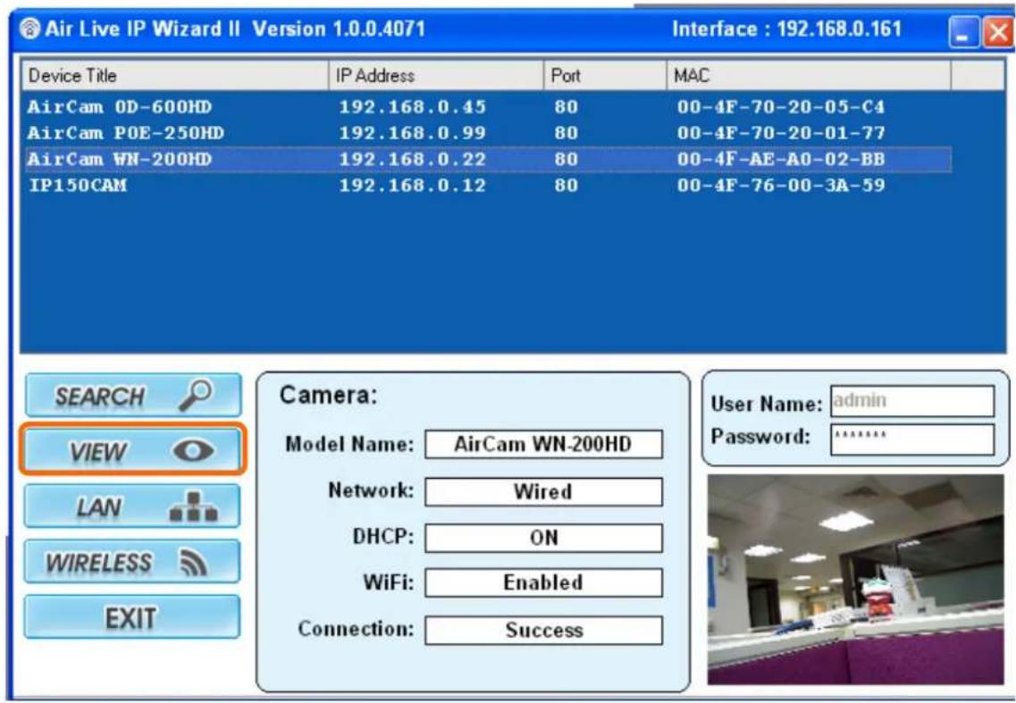
If IPWizard II finds network devices, View button will be available. Please select the device you want to view and click the View button. Then you could see the video from camera directly. Furthermore you could double click the left button of mouse to link to the network device by browser.
text_image
Air Live IP Wizard II Version 1.0.0.4071 Interface : 192.168.0.161 Device Title IP Address Port MAC AirCam 0D-600HD 192.168.0.45 80 00-4F-70-20-05-C4 AirCam POE-250HD 192.168.0.99 80 00-4F-70-20-01-77 AirCam WN-200HD 192.168.0.22 80 00-4F-AE-AO-02-BB IP150CAM 192.168.0.12 80 00-4F-76-00-3A-59 SEARCH VIEW LAN WIRELESS EXIT Camera: Model Name: AirCam WN-200HD Network: Wired DHCP: ON WiFi: Enabled Connection: Success User Name: admin Password: ****** User2.1.2 LAN
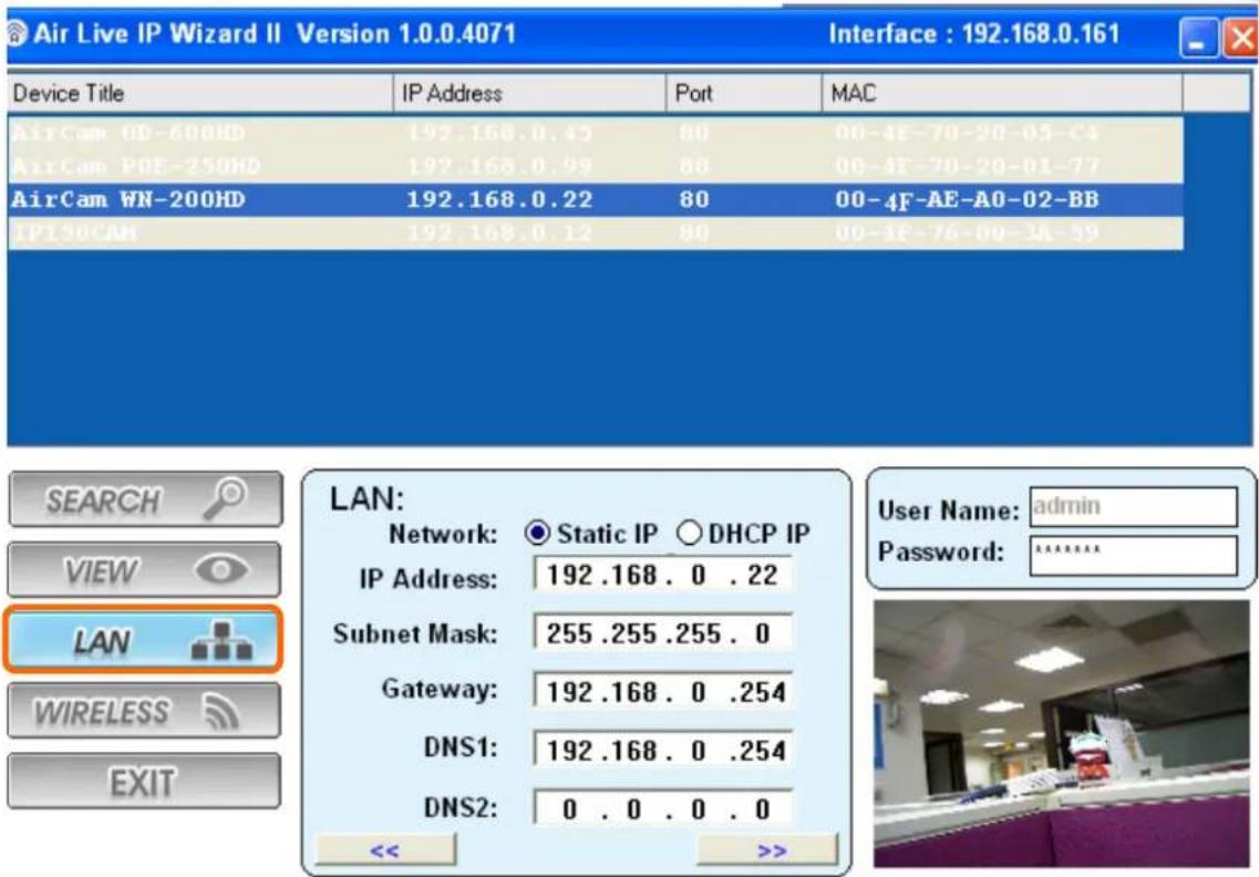
In case you want to change the IP related parameters of wired interface, please select the device you want to configure and click the LAN button. Relative settings will be carried out as below.
text_image
Air Live IP Wizard II Version 1.0.0.4071 Interface : 192.168.0.161 Device Title IP Address Port MAC AirCam 0D-600HD 192.168.0.45 80 00-4F-70-20-05-C4 AirCam PDE-250HD 192.168.0.49 80 00-4F-70-20-01-77 AirCam WN-200HD 192.168.0.22 80 00-4F-AE-AO-02-BB IP30CAM 192.168.0.12 80 00-4F-76-00-3A-59 SEARCH VIEW LAN WIRELESS EXIT LAN: Network: Static IP ○ DHCP IP IP Address: 192 .168 . 0 . 22 Subnet Mask: 255 .255 .255 . 0 Gateway: 192 .168 . 0 .254 DNS1: 192 .168 . 0 .254 DNS2: 0 . 0 . 0 . 0 << >>You could modify the relative settings of the selected device. Click “<<” button will quit the LAN setting procedure and click “>>” button will move to next page as below.
text_image
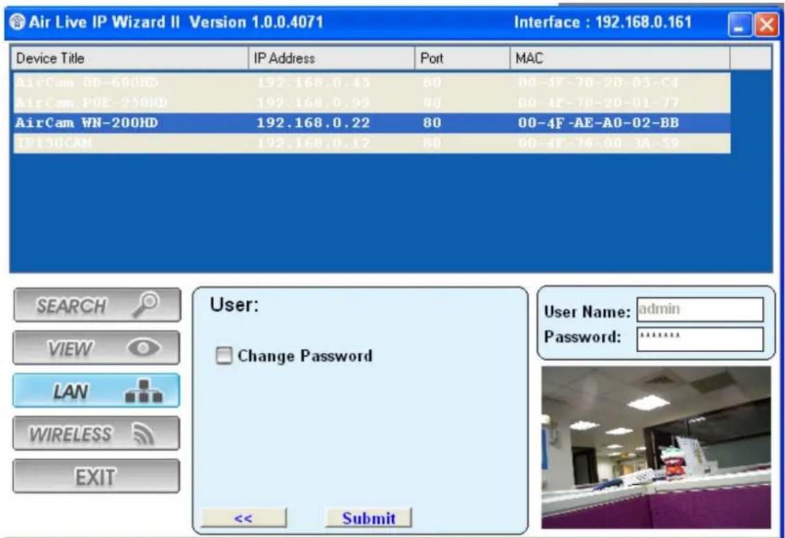
Air Live IP Wizard II Version 1.0.0.4071 Interface : 192.168.0.161 Device Title IP Address Port MAC AirCam 00-600HD 192.168.0.45 80 00-4F-70-20-03-C1 AirCam POE-250HD 192.168.0.99 80 00-4F-70-20-01-77 AirCam WN-200HD 192.168.0.22 80 00-4F-AE-AO-02-BB IP 30CAN 192.168.0.12 80 00-4F-76-00-3A-59 SEARCH VIEW LAN WIRELESS EXIT User: Change Password << Submit User Name: admin Password: ********In case, you do not want to change username and/or password, then just click "Submit" button to perform your setting accordingly. Click "<" button will go back to previous page.
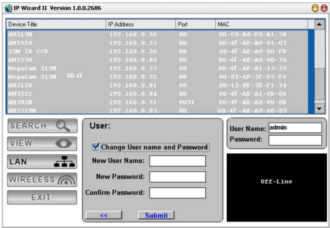
If you like to change username and/or password of the device, just click the check button. Then, the related fields will show up as below.
text_image
IP Wizard II Version 1.0.0.2686 Device Title IP Address Port MAC AM312M 192.168.0.56 80 00-C0-A8-F0-A1-38 AM5524 192.168.0.53 80 00-4F-AE-A0-01-03 25M IR CCD 192.168.0.58 80 00-4F-AE-A0-00-FD AM3230 192.168.0.82 80 00-4F-AE-A0-00-76 MegaCam 312M 192.168.0.57 80 00-4F-AE-A1-13-35 MegaCam 312M 00-4F 192.168.0.52 80 00-02-6F-3F-D5-F6 AM3120 192.168.0.81 80 00-12-BF-3E-F1-74 AM3221 192.168.0.84 80 00-4F-AE-A1-0D-06 AM381M 192.168.0.51 8051 00-4F-AE-A0-00-8D AM3519M 192.168.0.83 80 00-4F-AE-A0-00-85 SEARCH VIEW LAN WIRELESS EXIT User: ✓ Change User name and Password New User Name: New Password: Confirm Password: << Submit User Name: admin Password: Off-LineAfter keying in new username and password, click "Submit" button to perform your setting accordingly. Click "<<” button will go back to previous page.
2.1.3 Wireless
text_image
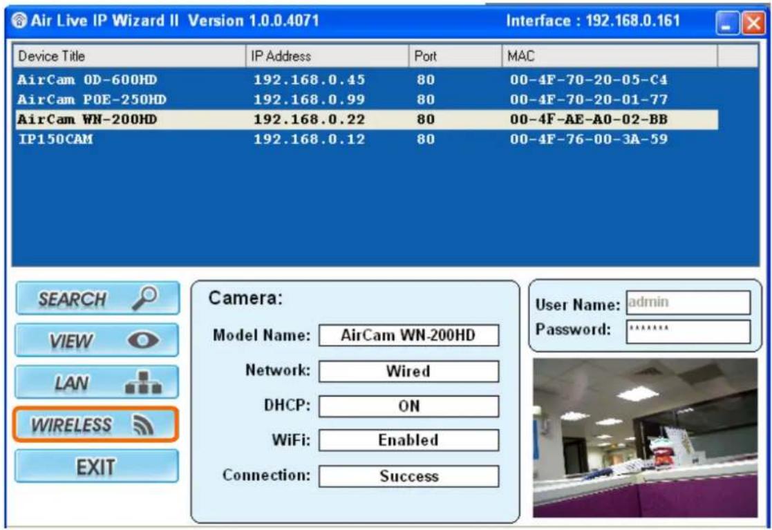
Air Live IP Wizard II Version 1.0.0.4071 Interface : 192.168.0.161 Device Title IP Address Port MAC AirCam OD-600HD 192.168.0.45 80 00-4F-70-20-05-C4 AirCam POE-250HD 192.168.0.99 80 00-4F-70-20-01-77 AirCam WN-200HD 192.168.0.22 80 00-4F-AE-AO-02-BB IP150CAM 192.168.0.12 80 00-4F-76-00-3A-59 SEARCH Camera: VIEW Camera: Network Camera Name: AirCam WN-200HD DHCP:Camera WiFi:Camera Connection:Camera User Name: admin Password: ******** WIRELESS EXITIn case you want to change the IP related parameters of wireless interface, please select the device you want to configure and click the WIRELESS button. Relative settings will be carried out as above.
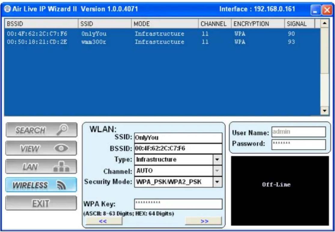
Click SSID to select your wireless AP or router and key in WEP or WPA key.
text_image
Air Live IP Wizard II Version 1.0.0.4071 Interface : 192.168.0.161 BSSID SSID MODE CHANNEL ENCRYPTION SIGNAL 00:4F:62:2C:C7:F6 OnlyYou Infrastructure 11 WPA 90 00:50:18:21:CD:2E wmm300r Infrastructure 11 WPA 93 WLAN: SSID: OnlyYou BSSID: 00:4F:62:2C:C7:F6 Type: Infrastructure Channel: AUTO Security Mode: WPA_PSK/WPA2_PSK WPA Key: statistically (ASCII: 8~63 Digits; HEX: 64 Digits) << >>Click >> to next step:
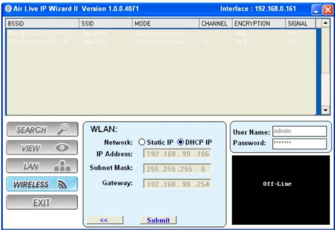
text_image
Air Live IP Wizard II Version 1.0.0.4071 Interface : 192.168.0.161 BSSID SSID MODE CHANNEL ENCRYPTION SIGNAL 00:4P:03:55:11:00 OnlyTou Infrastructure BI PCA 90 00:50:18:21:CDI 22 www300v Infrastructure BI PCA 93 WLAN: Network: Static IP DHCP IP IP Address: 192.168.99 .106 Subnet Mask: 255.255.255.0 Gateway: 192.168.99 .254 << Submit User Name: admin Password: ****** Off-LineMake sure wireless setting and then submit it.
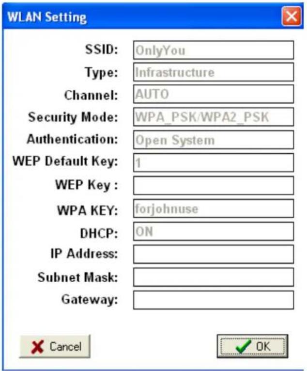
text_image
WLAN Setting SSID: OnlyYou Type: Infrastructure Channel: AUTO Security Mode: WPA_PSK/WPA2_PSK Authentication: Open System WEP Default Key: 1 WEP Key : WPA KEY: forjohnuse DHCP: ON IP Address: Subnet Mask: Gateway: Cancel OKClick OK to confirm these parameters, then IPWizard II will start to configure this camera with specified information.
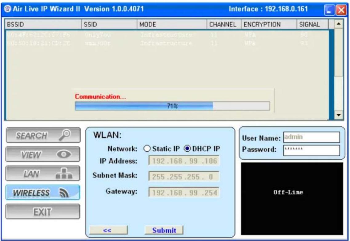
text_image
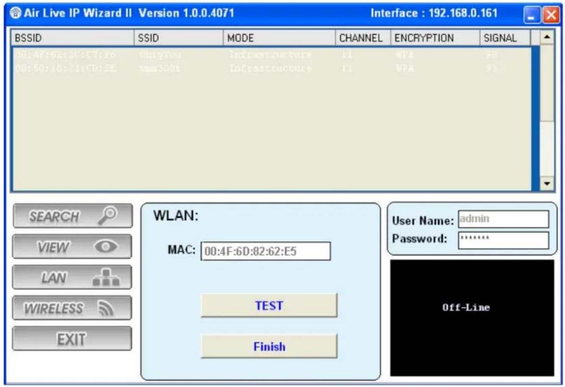
Air Live IP Wizard II Version 1.0.0.4071 Interface : 192.168.0.161 BSSID SSID MODE CHANNEL ENCRYPTION SIGNAL 00:47:62:20:07:Ps OnlyYou Infrastructure 11 VPA 90 00:50:18:21:CD:ZE www.400t Infrastructure 11 VPA 93 Communication... 71% SEARCH VIEW LAN WIRELESS EXIT WLAN: Network: ○ Static IP ● DHCP IP IP Address: 192.168.99 .106 Subnet Mask: 255.255.255 . 0 Gateway: 192.168.99 .254 << Submit User Name: admin Password: ****** Off-LineOnce this step finished, IPWizard II will prompt you to unplug the Ethernet cable to activate wireless access. Then IPWizard II will prompt you to test wireless setting or finish wireless procedure as below.
text_image
Air Live IP Wizard II Version 1.0.0.4071 Interface : 192.168.0.161 BSSID SSID MODE CHANNEL ENCRYPTION SIGNAL 00:4F:6D:05C7:Fe OnlyView Infrastructure 11 WPA 50 00:50:18:11tCD:2E vss300t Infrastructure 11 WPA 93 WLAN: MAC: 00:4F:6D:82:62:E5 TEST Finish User Name: admin Password: ****** OFF-Line2.2 UPnP for Windows
UPnP™ is short for Universal Plug and Play, which is a networking architecture that provides compatibility among networking equipment, software, and peripherals. This device is an UPnP enabled device. If the operating system, Windows XP, Vista or 7, of your PC is UPnP enabled, the Network Camera will be very easy to be found.
Please refer to Appendix I to enable UPnP settings only if your operating system of PC is running Windows XP.
Note: Windows 2000 does not support UPnP feature.
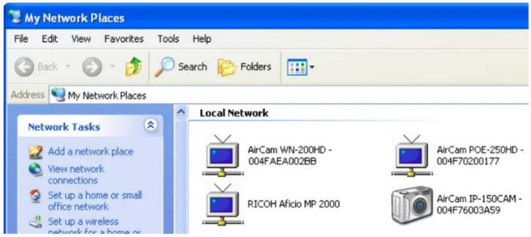
To discover your device, go to your Desktop and click My Network Places.
text_image
My Network Places File Edit View Favorites Tools Help Back Search Folders Address My Network Places Network Tasks Add a network place View network connections Set up a home or small office network Set up a wireless network for a home or Local Network AirCam WN-200HD - 004FAEA002BB AirCam POE-250HD - 004F70200177 RICOH Aficio MP 2000 AirCam IP-150CAM - 004F76003A59Click the targeted Device. Then Internet Explorer will connect to this Network Camera automatically.
2.3 Install the IP Camera behind NAT router
Once installed, the device is accessible on your LAN. To access the device from the Internet you must configure your broadband router to allow incoming data traffic to the device. If the device is installed on the LAN with a router, then it may get a dynamic IP address from the DHCP server. However, if the device wants to be accessed from the WAN, its IP address needs to be setup as fixed IP, also the port forwarding or Virtual Server function of router needs to be setup.
However, if your NAT router supports UPnP feature, it can be very easy to achieve NAT traversal automatically. To do this, enable the NAT-traversal feature, which will attempt to automatically configure the router to allow access to the camera.
Installing the device with an UPnP router on your network is an easy 3-step procedure:
(1) Enable UPnP option of your NAT router
(2) Enable UPnP NAT traversal option of the Network Camera (default)
(3) Access your Network Camera by DIPS
(1) Enable UPnP option of your NAT router
To use UPnP IGD function (NAT traversal), you need to make sure the UPnP function is enabled in your router. Most new home routers should support this function. Some of routers are default enable and others are not. Please check user's manual of your NAT router for detail.
(2) Enable UPnP NAT traversal option of the Network Camera
Refer to Setting → Network → UPnP page for detail NAT traversal setting. Note that this option is default enabled.
(3) Access your Network Camera by DIPS
Refer to Setting → System → System page for detail DIPS information.
2.4 Configure IP Camera via Web UI
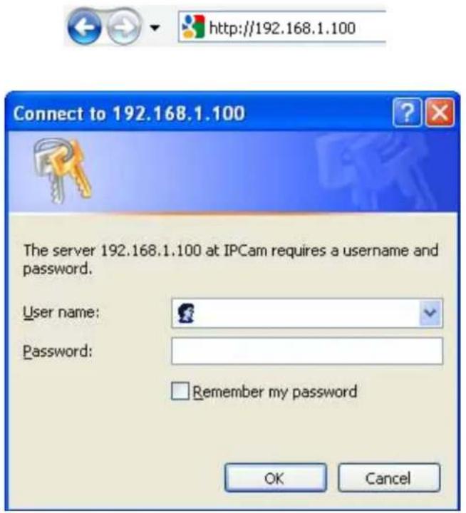
- Start the web browser on the computer and type the IP address of the Camera you want to monitor as below:
The Login Window of the Camera is prompted:
text_image
http://192.168.1.100 Connect to 192.168.1.100 The server 192.168.1.100 at IPCam requires a username and password. User name: Password: Remember my password OK Cancel- Type in your login name and password under "USERNAME" and "PASSWORD" textbox. For the first time use (default value), input the User Name: admin
Password: airlive
That's, type in "admin" on the "USERNAME" as a default name and "airlive" on the "PASSWORD" as a default password. Click "OK" button to start the main menu.
-
According your browser's security setting, the IE Web Page may prompt the "Security Warning" window. If so, select "Yes" to install and run the ActiveX control into your PC. Otherwise, the system will load the ActiveX silently.
-
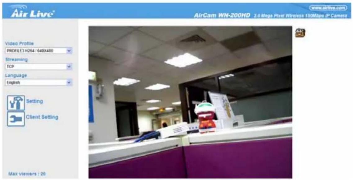
After the ActiveX control was installed and ran, the first image will be displayed.
-
According your browser's security setting, the IE Web Page may prompt the "Security Warning" window. If so, select "Yes" to install and run the ActiveX control into your PC. Otherwise, the system will load the ActiveX silently.
- After the ActiveX control was installed and ran, the first image will be displayed.
text_image
Air Live® AirCam WN-200HD 3.9 Mega Pixel Wireless 150Mbps IP Cameras Video Profile PROFILE3 H264 / 640X480 Streaming TCP Language English Setting Client Setting Max viewers : 202.4.1 Login as User
If you log in the Camera as an ordinary User, "Setting" function will be not accessible.
2.4.2 Login as Administrator
If you log in the Camera as the Administrator, you can perform all the settings provided by the device.
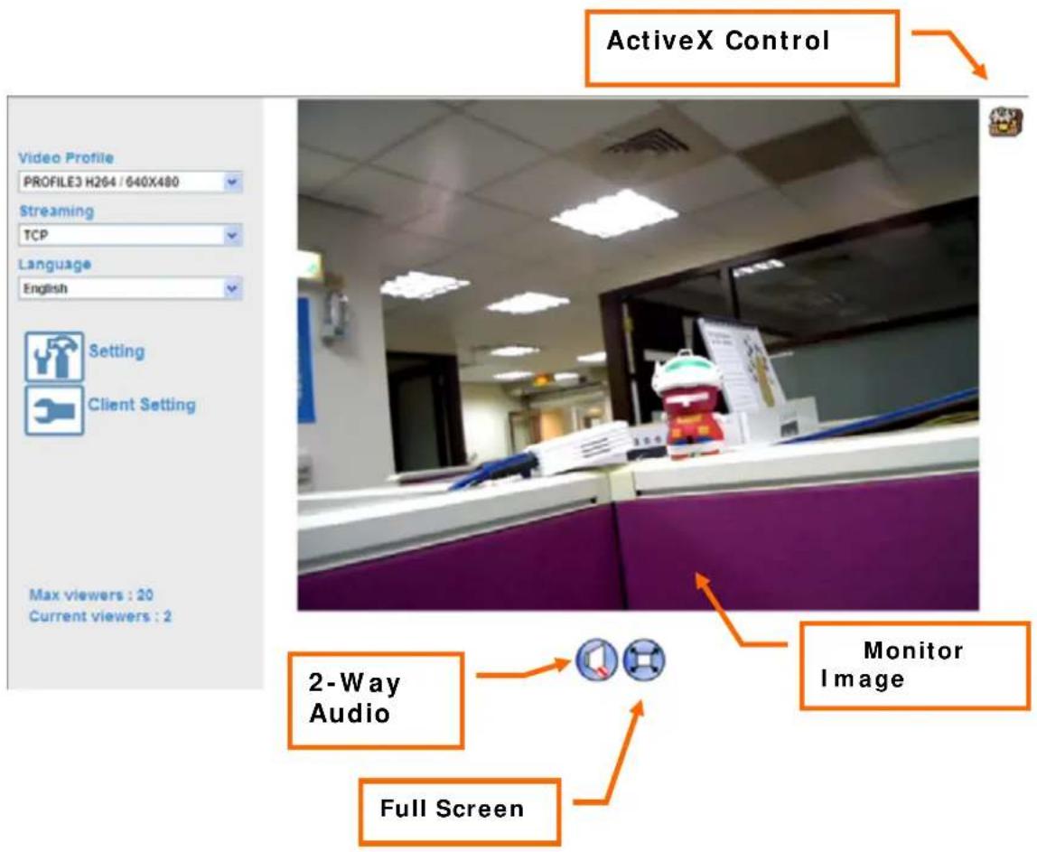
Start-up screen will be as follow no matter an ordinary users or an administrator.
text_image
ActiveX Control Video Profile PROFILE3 H264 / 640X480 Streaming TCP Language English Setting Client Setting Max viewers : 20 Current viewers : 2 2-Way Audio Monitor Image Full Screen3
Configure the Camera
3.1 Monitor the Image Section
The image shot by the device is shown here. The date and time are displayed at the top of the window.
3.2 View Profile
The device supports multi-profile function for H.264, MEPG4 and JPEG simultaneously. User can chose the proper and/or preferred profile which is listed here.
3.3 Streaming Protocol
User can select proper streaming protocol according to networking environment.
3.4 Language
The device could provide multiple languages to meet customer's requirement.
3.5 Two-Way Audio
The device supports 2-way audio function. User can chose to enable or disable this function by toggling the icon below.

: Disable audio uploading function.

: Enable audio uploading function.
3.6 Full Screen
Enlarge video to full screen display.

: Enlarge video to full screen display. Press "ESC" key to disable this function.
3.7 Active Control
The plug-in ActiveX control supports a lot of functions by clicking the left mouse button. Note that this feature only supports on the ActiveX control within Microsoft® Internet Explorer.
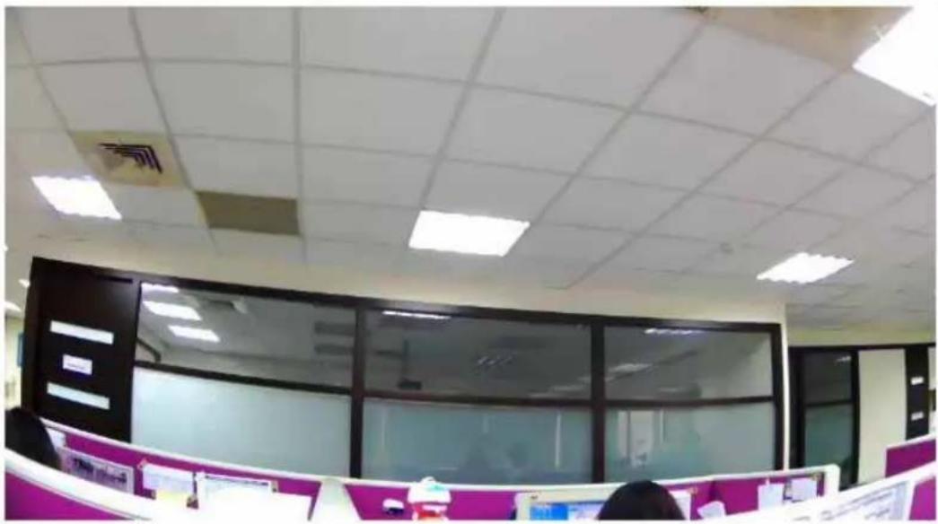
On the ActiveX control icon, click the LeftMouseButton, then a menu pop-up. This menu provides features that are unique to the ActiveX control. These features include:
- "Digital Zoom",
- "Snapshot",
- "Record",
• "Volume", - "About"
natural_image
Interior view of an office with cubicles and large windows (no visible text or symbols)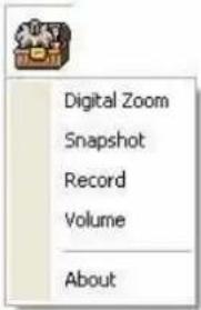
text_image
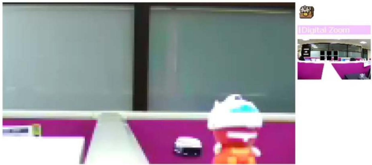
Digital Zoom Snapshot Record Volume About3.7.1 Digital Zoom
text_image
IDigital ZoomClick Digital Zoom to active this function as above. User can drag or scale the box over the video to adjust zoom ratio and position.
3.7.2 Snapshot
text_image
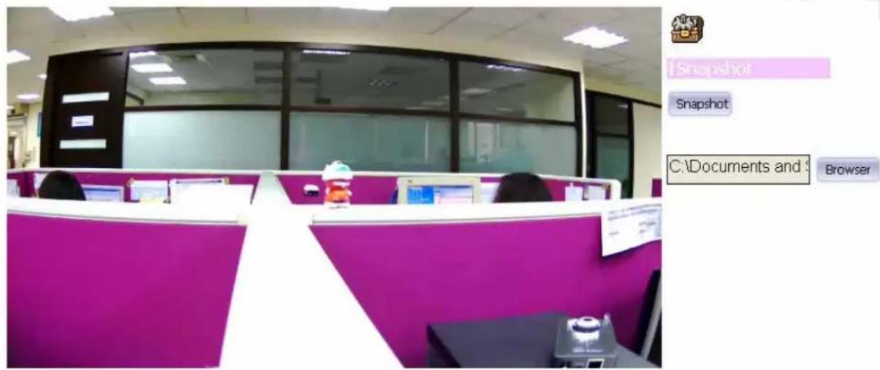
1Snapshot Snapshot C:\Documents and BrowserClick Snapshot to activate this function. Press Snapshot button to take a picture. The image file is saved as JPEG format into your local PC. Select Browser, the pop-up window to select the save path and file name prefix, select OK to continue.
If you like to retrieve the saved image, select the file to display the saved image by using any one of graph editing tools.
3.7.3 Record
text_image
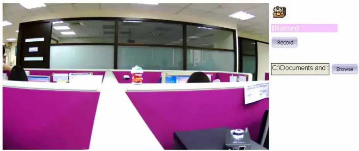
Record Record C:\Documents and BrowseClick Record to activate this function. Press Record button to start recording. The video file is saved as ASF format into your local PC. While you want to
stop it, press Stop to stop recording. Select Browser, the pop-up window to select the save path and file name prefix, select OK to continue.
After stop recording, list the files, this file is named as Video_yyyymmddhhmmss.avi
The ASF files can be displayed by the standard Windows Media Player, but it needs the DixectX 9.0 or later version to be installed.
3.7.4 Volume
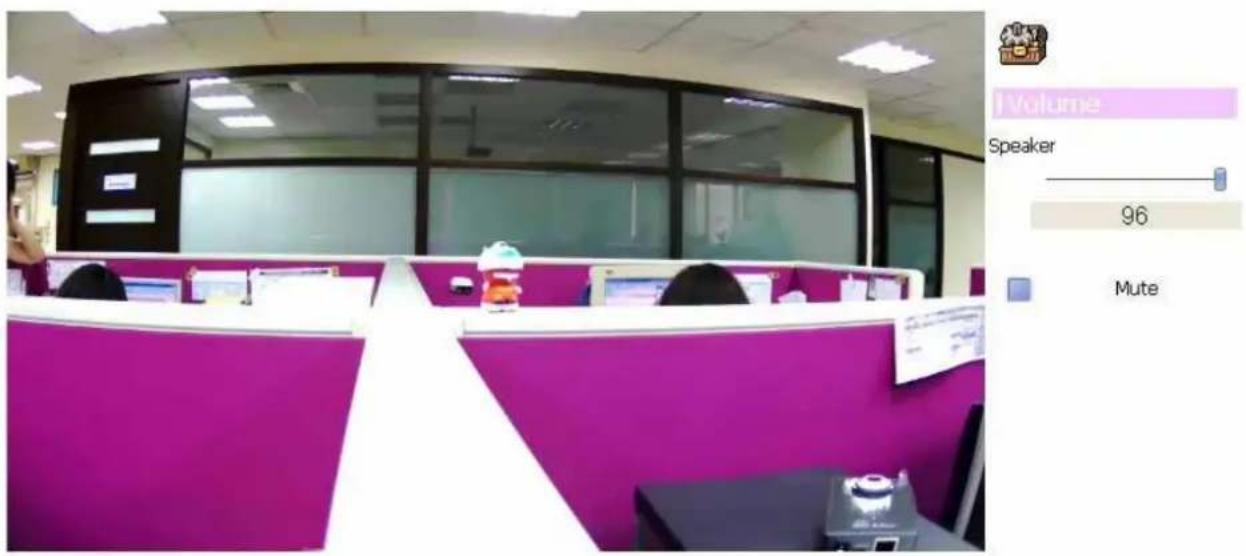
Click Volume to activate this function. There are two control bars for speaker and microphone volume respectively. Scroll these control bars to adjust the audio attribute. Check the volume mute will mute the speaker output.
text_image
Volume Speaker 96 Mute3.7.5 About
natural_image
Interior view of a modern office with purple and white desks, no visible text or signage
Shinshao
text_image
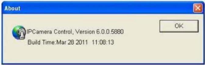
About IPCamera Control, Version 6.0.0.5880 Build Time:Mar 28 2011 11:08:13Click About to show this ActiveX information.
4
Monitor the Image Section
4.1 Monitor the Image Section
This function is only available for user logged into Camera as administrator.
Click on each menu name to display its setting page.
| Item Action | |
| Network | Configure Network settings such as DHCP, DDNS, 3GPP, PPPoE and UPnP |
| Camera | Adjust camera parameters, position, and set camera tour |
| System | Configure system information, date & time, maintenance, and view system log file. |
| Video | Configure bit rate and frame rate of video profiles |
| Audio | Configure audio parameters |
| User | Setup user name, password and login privilege |
| Setup E-Mail configuration | |
| Object Detection | Setup Object detection |
| Storage | Status and configuration of SD card |
| Recording List | Files list inside the SD Card |
| Event Server | Setup FTP/TCP/HTTP server for event |
| Event Schedule | Configure the schedule while event triggered |
4.2 Configure via Web UI
4.2.1 Network
Use this menu to configure the network to connect the device and the clients. This section provides the menu for connecting the device through Ethernet cable.

text_image
Network Wireless DDNS PPPoE Streaming UPnP Bonjour IP Filter IP NotificationMAC Address
00:4F:AE:A0:01:E4
√ Obtain IP address automatically (DHCP)
IP Address
192.168.0.71
Test
Subnet Mask
255.255.255.0
Gateway
192.168.0.254
√ Obtain DNS from DHCP
Primary DNS
192.168.0.254
Secondary DNS
[Non-Text]
HTTP Port
80 (1 \~ 65535) Test
MAC address:
Displays the Ethernet MAC address of the device. Note that user can not change it.
Obtain IP address automatically (DHCP):
DHCP: Stands for Dynamic Host Configuration Protocol.
Enable this checked box when a DHCP server is installed on the network to issue IP address assignment. With this setting, the IP address is assigned automatically. If this device can not get an IP address within limited tries, the device will assign a default IP address, 192.168.1.100, by itself as the default IP address.
IP address, Subnet mask, and Gateway:
If you do not select Obtain an IP address automatically, then you need to enter these network parameters manually.
Obtain DNS from DHCP:
DNS: Stands for Domain Name System.
Enable this checked box when a DHCP server is installed on the network and provide DNS service.
Primary DNS and Secondary DNS:
If you do not select Obtain DNS from DHCP, then you need to enter these parameters manually.
HTTP Port:
The device supports two HTTP ports. The first one is default port 80 and this port is fixed. This port is very useful for Intranet usage. The second HTTP port is changeable. Users could assign the second port number of http protocol, and the WAN users should follow the port number to login. If the http port is not assigned as 80, users have to add the port number in back of IP address. For example: http://192.168.1.100:8080.
Therefore, the user can access the device by either
http://xx.xx.xx.xx/, or
http://xx.xx.xx.xx:xxxx/ to access the device.
If multiple devices are installed on the LAN and also required to be accessed from the WAN, then the HTTP Port can be assigned as the virtual server port mapping to support multiple devices.
Click "OK" to save and enable the setting.
4.2.2 Wireless
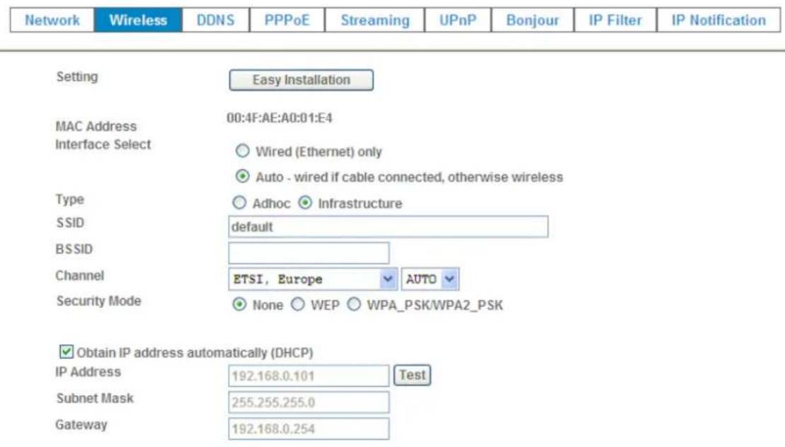
If your device is a wireless model, you could assign the related parameters into wireless setting. Using a wired connection ensures greater secrecy while making these settings. These settings should always be made in the camera first and secondly in the wireless access point. This ensures that the device is always accessible when making changes.
Note that this function is only available for the model with WLAN capability.
text_image
Network Wireless DDNS PPPoE Streaming UPnP Bonjour IP Filter IP Notification Setting Easy Installation MAC Address 00:4F:AE:A0:01:E4 Interface Select Wired (Ethernet) only Auto - wired if cable connected, otherwise wireless Type Adhoc Infrastructure SSID default BSSID Channel ETSI, Europe AUTO Security Mode None WEP WPA_PSK/WPA2_PSK Obtain IP address automatically (DHCP) IP Address 192.168.0.101 Test Subnet Mask 255.255.255.0 Gateway 192.168.0.254Setting (Easy Installation):
Provides a 2-step procedure to configure wireless setting:
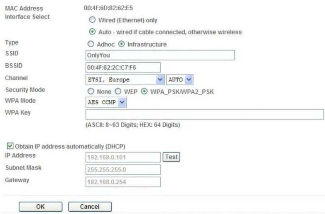
Step 1: Select SSID of wireless router or access point (AP).
text_image
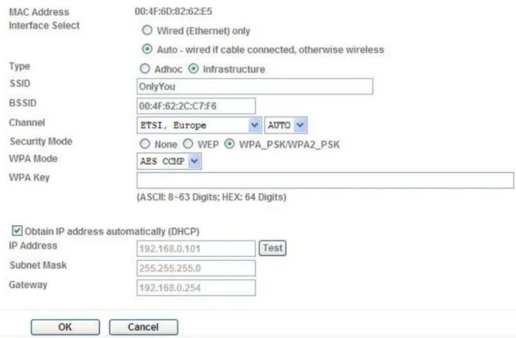
MAC Address Interface Select 00:4F:6D:82:62:E5 Wired (Ethernet) only Auto - wired if cable connected, otherwise wireless Type Adhoc Infrastructure SSID OnlyYou BSSID 00:4F:62:2C:C7:F6 Channel ETSI, Europe AUTO Security Mode None WEP WPA_PSK/WPA2_PSK WPA Mode AES CCMP WPA Key (ASCII: 8~63 Digits; HEX: 64 Digits) Obtain IP address automatically (DHCP) IP Address 192.168.0.101 Test Subnet Mask 255.255.255.0 Gateway 192.168.0.254 OK CancelStep 2: Key in security key of WEP or WPA. Then click "Submit" button to activate wireless setting.
text_image
MAC Address Interface Select 00:4F:6D:82:62:E5 Wired (Ethernet) only Auto - wired if cable connected, otherwise wireless Type Adhoc Infrastructure SSID OnlyYou BSSID 00:4F:62:2C:C7:F6 Channel ETSI, Europe AUTO Security Mode None WEP WPA_PSK/WPA2_PSK WPA Mode AES CCMP WPA Key (ASCII: 8~63 Digits; HEX: 64 Digits) Obtain IP address automatically (DHCP) IP Address 192.168.0.101 Test Subnet Mask 255.255.255.0 Gateway 192.168.0.254 OK CancelIn case, user wants to configure wireless settings manually, please follow the steps as below:
MAC address:
Displays the Ethernet MAC address of the WLAN card. Note that user can not change it.
Site survey:
Click the “Refresh” button. It will refresh information window which list is the result of a network scan. Access points with a disabled SSID Broadcast will not appear unless the camera is associated with it. The following information is provided:
Interface Select:
"Wired (Ethernet) only" or "Auto – wired if cable connected, otherwise wireless":
Choose wired or wireless mode. However, note that wired is priority.
Type:
To select one of WLAN modes from Infrastructure or Ad-Hoc mode.
Security mode:
Shows which type of security the network uses. The device supports three security methods:
None
WEP
WPA_PSK/WPA2_PSK
SSID:
This is the name of the wireless network the device is configured for. The field accepts up to 32 alphanumeric characters. The name must be exactly the same as that used in the wireless access point, or the connection will not be established.
Leaving this field blank means the device will attempt to access the nearest open network.
Channel:
Chooses the wireless channel in use currently.
WEP settings:
- Authentication:
Select Open or Shared Key System Authentication, depending on the method used by your access point. Not all access points have this option, in which case they probably use Open System, which is sometimes known as SSID Authentication.
- WEP Mode:
The key types available depend on the access point being used. The following options are available:
- ASCII - In this method the string must be exactly 5 characters for 64-bit WEP and 13 characters for 128-bit WEP.
- HEX - In this method the string must be exactly 10 hexadecimal (0-9, A-F) characters for 64-bit WEP and 26 hexadecimal characters for 128-bit WEP.
- Web Key 1\~4:
Key value of WEP.
WPA settings:
- WPA Key:
Key value of WPA. The device uses a pre-shared key (PSK) for key management. The pre-shared key can be entered either as Manual hex, as 64 hexadecimal characters, or as a Passphrase, using 8 to 63 ASCII characters.
Obtain IP address automatically (DHCP):
Enable this checked box when a DHCP server is installed on the network to issue IP address assignment. With this setting, the IP address is assigned automatically.
IP address, Subnet mask, and Gateway:
If you do not select Obtain an IP address automatically, then you need to enter these network parameters manually.
Select "OK" to save and enable the setting.
Note: To enable WLAN function, user must set these related parameters correctly at first. Then power off the device and remove Ethernet cable from device. Power on the device again and WLAN mode will be available accordingly.
4.2.3 DDNS
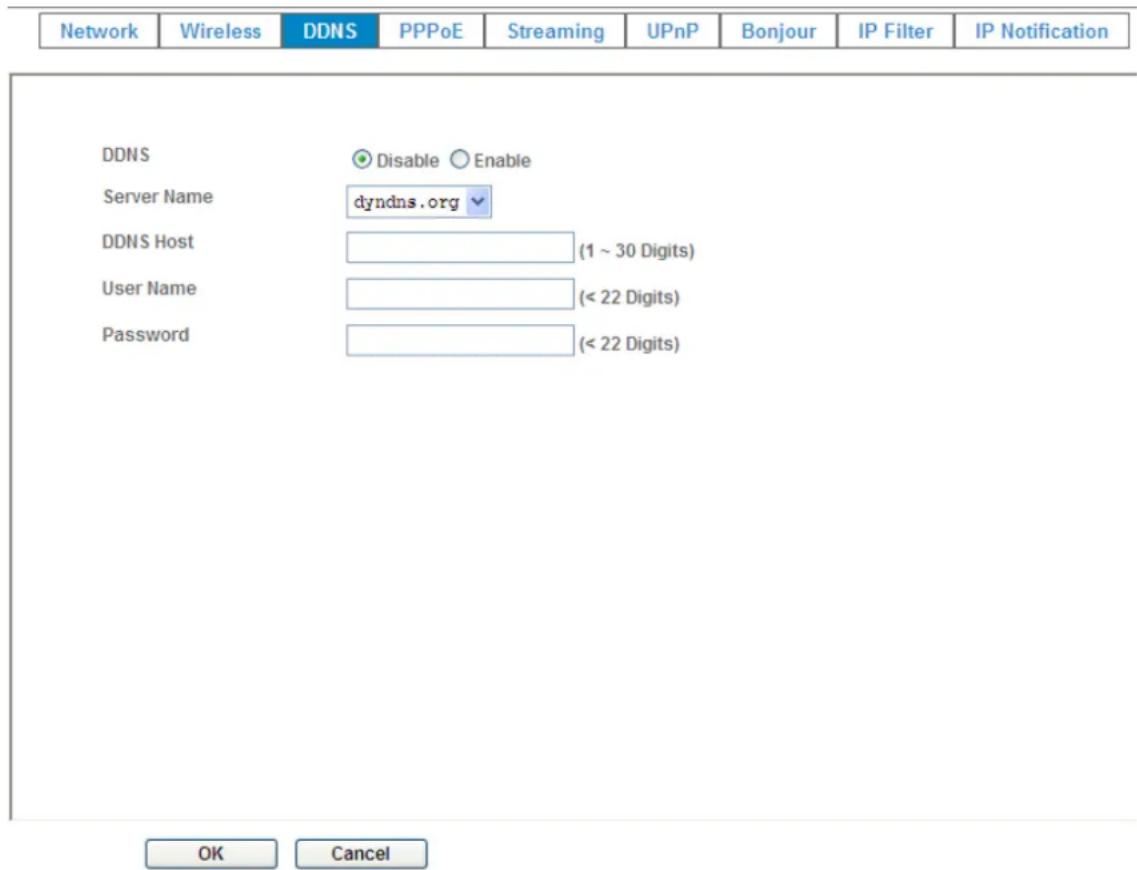
DDNS: Stands for Dynamic Domain Name Server
Your Internet Service Provider (ISP) provides you at least one IP address which you use to connect to the Internet. The address you get may be static, meaning it never changes, or dynamic, meaning it's likely to change periodically. Just how often it changes, depends on your ISP. A dynamic IP address complicates remote access since you may not know what your current WAN IP address is when you want to access your device over the Internet. One of the possible solutions to the dynamic IP address problem comes in the form of a dynamic DNS service.
A dynamic DNS service is unique because it provides a means of updating your IP address so that your listing will remain current when your IP address changes. There are several excellent DDNS services available on the Internet.
One such service you can use is www.DynDNS.org. You'll need to register with the service and set up the domain name of your choice to begin using it. Please refer to the home page of the service for detailed instructions or refer to Appendix G for more information.
If your device is connected to xDSL directly, you might need this feature. However, if your device is behind a NAT router, you will not need to enable this feature because your NAT router should take care of this job. As to xDSL environment, most of the users will use dynamic IP addresses. If users want to set up a web or a FTP server, then the Dynamic Domain Name Server is necessary.
text_image
Network Wireless DDNS PPPoE Streaming UPnP Bonjour IP Filter IP Notification DDNS Disable Enable Server Name dyndns.org DDNS Host (1 ~ 30 Digits) User Name (< 22 Digits) Password (< 22 Digits) OK CancelDDNS:
To enable or disable the DDNS service here.
Server name:
Choose the built-in DDNS server.
DDNSHost:
The domain name is applied of this device.
User name:
The user name is used to log into DDNS.
Password:
The password is used to log into DDNS.
4.2.4 PPPoE
PPPoE: Stands for Point to Point Protocol over Ethernet
A standard builds on Ethernet and Point-to-Point network protocol. It allows your device with xDSL or cable connects with broadband network directly, then your device can dial up and get a dynamic IP address. For more PPPoE and Internet configuration, please consult your dealer or ISP.
The device can directly connect to the xDSL, however, it should be setup on a LAN environment to program the PPPoE information first, and then connect to the xDSL modem. Power on again, then the device will dial on to the ISP connect to the WAN through the xDSL modem.
The procedures are
- Connect to a LAN by DHCP or Fixed IP
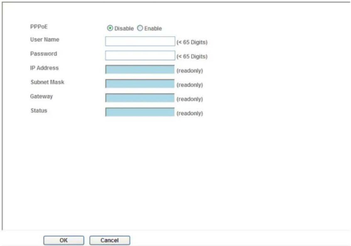
- Access the device; enter Setting → Network → PPPoE as below
Network Wireless DDNS PPPoE Streaming UPnP Bonjour IP Filter IP Notification
text_image
PPPoE User Name (< 65 Digits) Password (< 65 Digits) IP Address (readonly) Subnet Mask (readonly) Gateway (readonly) Status (readonly) OK CancelPPPoE:
To enable or disable the PPPoE service here.
User name:
Type the user name for the PPPoE service which is provided by the ISP.
Password:
Type the password for the PPPoE service which is provided by the ISP.
IP address, Subnet mask, and Gateway (read only):
Shows the IP information got from PPPoE server site.
Status:
Shows the Status of PPPoE connection.
4.2.5 Steaming
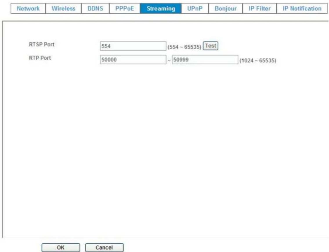
RTSP is a streaming control protocol, and a starting point for negotiating transports such as RTP, multicast and Unicast, and for negotiating codecs. RTSP can be considered a "remote control" for controlling the media stream delivered by a media server. RTSP servers typically use RTP as the protocol for the actual transport of audio/video data.
RTSP Port:
Choose the RTSP port. The RTSP protocol allows a connecting client to start a video stream. Enter the RTSP port number to use. The default value is 554.
RTP Port:
Specify the range of transmission port number of video stream. The default range is 50000 to 50999. User can specify a number between 1024 and 65535.
text_image
Network Wireless DDNS PPPoE Streaming UPnP Bonjour IP Filter IP Notification RTSP Port 554 (554 ~ 65535) Test RTP Port 50000 ~ 50999 (1024 ~ 65535) OK Cancel4.2.6 UPnP
UPnP is short for Universal Plug and Play, which is a networking architecture that provides compatibility among networking equipment, software, and peripherals. This device is an UPnP enabled Network Camera. If your operating system is UPnP enabled, the device will automatically be detected and a new icon will be added to "My Network Places." If you do not want to use the UPnP functionality, it can be disabled.
In addition, this device also provides UPnP IGD function for NAT traversal easily. Use NAT traversal when your device is located on an intranet (LAN) and you wish to make it available from the other (WAN) side of a NAT router. With NAT traversal properly configured, all HTTP traffic to an external HTTP port in the NAT router will be forwarded to the device.
| Network | Wireless | DDNS | PPPoE | Streaming | UPnP | Bonjour | IP Filter | IP Notification |
text_image
UPnP Disable Enable Friendly Name AirCam WN-200HD - 004FAEA002BB (readonly) UPnP NAT Traversal Disable Enable Port Range 32768 ~ 65535 (1 ~ 65535) External IP Address (readonly)
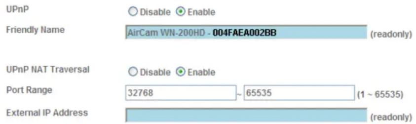
UPnP:
To enable or disable the UPnP service here.
Friendly Name:
Shows the friendly name of this device here.
UPnP NAT Traversal
When enabled, the device will attempt to configure port mapping in a NAT router on your network, using UPnP ^TM . Note that UPnP ^TM must be enabled in the NAT router first.
Port Range:
The port range will open in NAT router.
External IP address:
Show the IP address and port for WAN access through Internet. If NAT traversal is configured successfully, user can use this IP address and port to access this device. The external IP address is not shown in case NAT traversal function is failed.
4.2.7 Bonjour
Bonjour, also known as zero-configuration networking, enables automatic discovery of computers, devices, and services on IP networks. Bonjour uses industry standard IP protocols to allow devices to automatically discover each other without the need to enter IP addresses or configure DNS servers. Specifically, Bonjour enables automatic IP address assignment without a DHCP server, name to address translation without a DNS server, and service discovery without a directory server. Bonjour is an open protocol which Apple has submitted to the IETF as part of the ongoing standards-creation process.
Bonjour:
To enable or disable the Bonjour service here.
Friendly Name:
Shows the friendly name of this device here.
| Network | Wireless | DDNS | PPPoE | Streaming | UPnP | Bonjour | IP Filter | IP Notification |
Bonjour
Friendly Name
○ Disable ● Enable
AirCam WN-200HD - 004FAEA002BB (readonly)
OK
Cancel
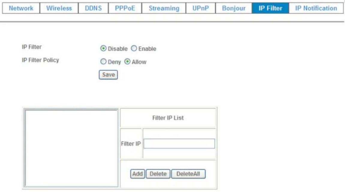
4.2.8 IP Filter
You can enter different user's IP address which are allowing enter or denying by the device.
IP Filter:
To enable or disable the IP filter function here.
IP Filter Policy:
Choose the filter policy where is denying or allowing.
text_image
Network Wireless DDNS PPPoE Streaming UPnP Bonjour IP Filter IP Notification IP Filter Disable Enable IP Filter Policy Deny Allow Save Filter IP List Filter IP Add Delete DeleteAll4.2.9 IP Notification
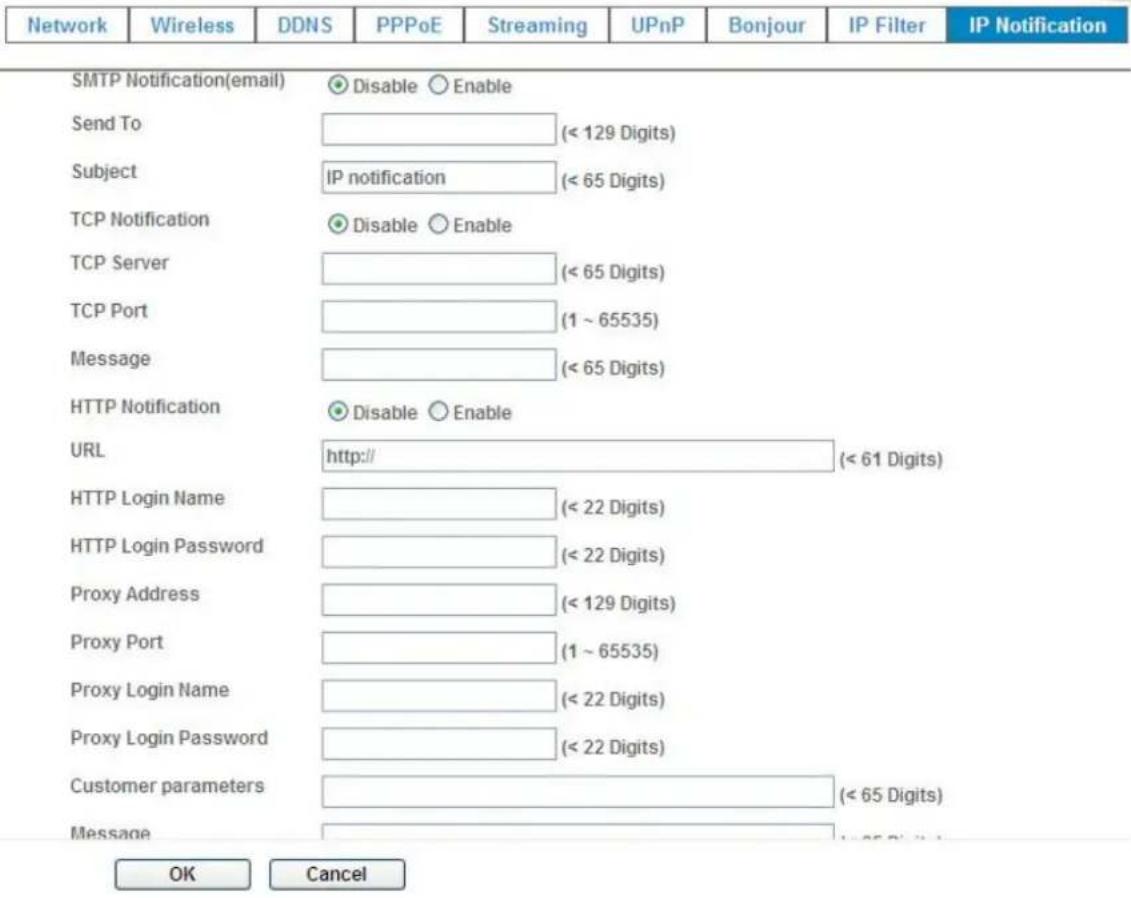
In case the IP address is changed, system is able to send out an email to alert someone if the function is enabled.
SMTP Notification (e-mail):
If enable this function, then the "Send to" and "Subject" fields need to be filled.
Send To:
Type the receiver's e-mail address. This address is used for reply mail.
Subject:
Type the subject/title of the E-mail.
TCP Notification:
If enable this function, then the "TCP Server", "TCP Port", and "Message" fields need to be filled.
TCP Server:
Type the server name or the IP address of the TCP server.
text_image
Network Wireless DDNS PPPoE Streaming UPnP Bonjour IP Filter IP Notification SMTP Notification(email) Disable Enable Send To (< 129 Digits) Subject IP notification (< 65 Digits) TCP Notification Disable Enable TCP Server (< 65 Digits) TCP Port (1 ~ 65535) Message (< 65 Digits) HTTP Notification Disable Enable URL http:// (< 61 Digits) HTTP Login Name (< 22 Digits) HTTP Login Password (< 22 Digits) Proxy Address (< 129 Digits) Proxy Port (1 ~ 65535) Proxy Login Name (< 22 Digits) Proxy Login Password (< 22 Digits) Customer parameters (< 65 Digits) Message < 65 Digits OK CancelTCP Port:
Set port number of TCP server.
Message:
The message will be sent to FTP server.
HTTP Notification:
If enable this function, then the fields below need to be filled.
URL:
Type the server name or the IP address of the HTTP server.
HTTP Login name:
Type the user name for the HTTP server.
HTTP Login Password:
Type the password for the HTTP server.
Proxy Address:
Type the server name or the IP address of the HTTP Proxy.
Proxy Port:
Set port number of Proxy.
Proxy Login name:
Type the user name for the HTTP Proxy.
Proxy Login Password:
Type the password for the HTTP Proxy.
Custom parameter:
User can set specific parameters to HTTP server.
Message:
The message will be sent to HTTP server.
4.3 Camera – Adjust Camera Parameters
Use this menu to set the functions of the camera parameters of the device.
4.3.1 Picture
Picture Privacy Mask
text_image
Rotation Normal White Balance Auto Exposure Control Auto Hold Maximum Exposure Time 1/5 S Color Level 70 (0 ~ 100) Brightness 50 (0 ~ 100) Contrast 50 (0 ~ 100) Sharpness 50 (0 ~ 100) De-Noise Off Default Settings Default Settings
natural_image
Interior view of an office cubicle with purple walls and ceiling lights, no visible text or symbolsRotation:
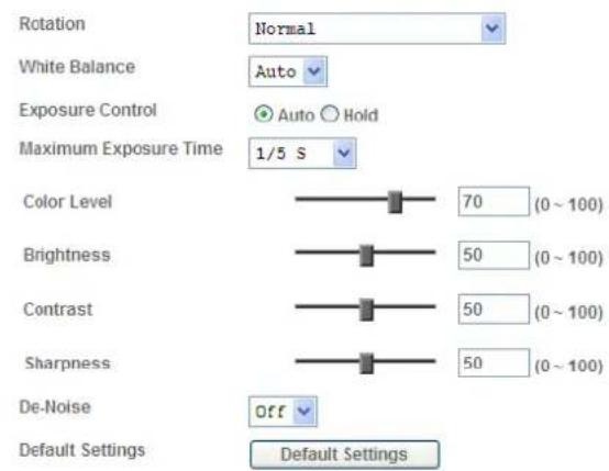
Turn the "Mirror" and "Vertical Flip" On or OFF. The image will be overturned as below.

text_image
Normal Image Mirror Inside Vertical Flip Mirror + Vertical Flip ImageWhite Balance:
Auto: will adjust the white balance automatically. Hold: will hold the white balance.
Exposure Control:
Auto: will adjust the internal gain automatically. Hold: will hold the internal gain.
Color Level:
Large value will be colorful.
Brightness:
Large value will brighten camera.
Sharpness:
Large value will sharpen camera.
Contrast:
Large value will contrast camera heavily.
De-Noise:
De-Noise can remove or lower unwanted noise and preserve fine details and edges.
Default Settings:
Restore to factory image settings.
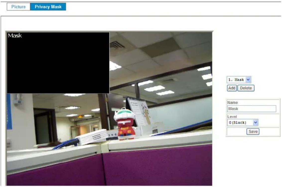
4.3.2 Privacy Mask
Use this page to specify privacy mask window 1 to window 7 and set the name and gray level for selected window.
Add and Delete:
To add or delete the privacy mask windows, user can specify up to 7 windows to mask the video captured by this device. By dragging mouse on the image, you can change the position and size of the selected window accordingly.
Name:
Name of the specified window.
Level
Defines the gray level of mask block. The lower value will be darker.
text_image
Picture Privacy Mask Mask 1. Mask Add Delete Name Mask Level 0 (Black) Save4.4 System – Configure and Maintain
Use this menu to perform the principal settings of the device.
4.4.1 System
text_image
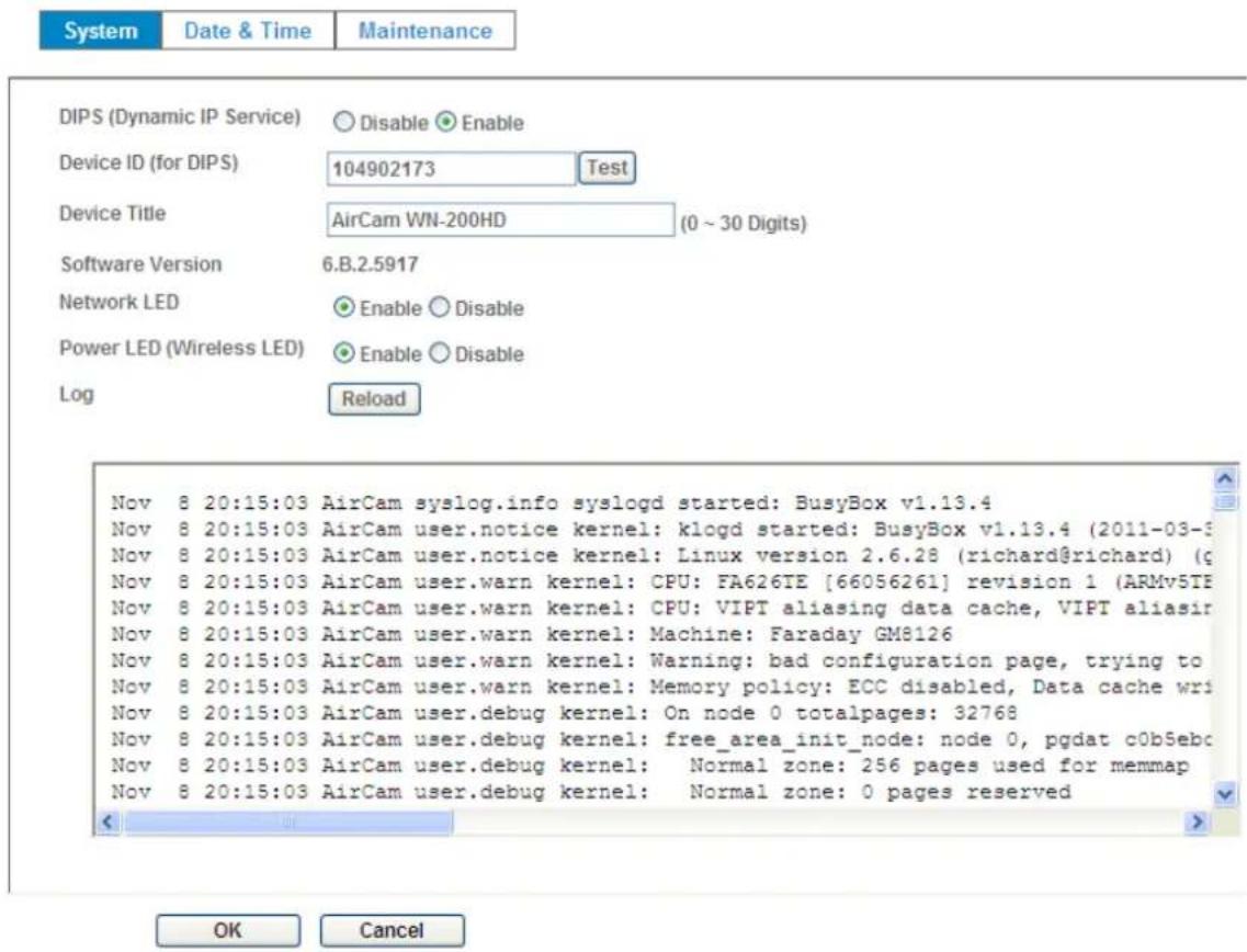
System Date & Time Maintenance DIPS (Dynamic IP Service) Disable Enable Device ID (for DIPS) 104902173 Test Device Title AirCam WN-200HD (0 ~ 30 Digits) Software Version 6.B.2.5917 Network LED Enable Disable Power LED (Wireless LED) Enable Disable Log Reload Nov 8 20:15:03 AirCam syslog.info syslogd started: BusyBox v1.13.4 Nov 8 20:15:03 AirCam user.notice kernel: klogd started: BusyBox v1.13.4 (2011-03-5) Nov 8 20:15:03 AirCam user.notice kernel: Linux version 2.6.28 (richard@richard) (g Nov 8 20:15:03 AirCam user.warn kernel: CPU: FA626TE [66056261] revision 1 (ARMv5TE Nov 8 20:15:03 AirCam user.warn kernel: CPU: VIPT aliasing data cache, VIPT aliasir Nov 8 20:15:03 AirCam user.warn kernel: Machine: Faraday GM8126 Nov 8 20:15:03 AirCam user.warn kernel: Warning: bad configuration page, trying to Nov 8 20:15:03 AirCam user.warn kernel: Memory policy: ECC disabled, Data cache wri Nov 8 20:15:03 AirCam user.debug kernel: On node 0 totalpages: 32768 Nov 8 20:15:03 AirCam user.debug kernel: free_area_init_node: node 0, pgdat c0b5ebo Nov 8 20:15:03 AirCam user.debug kernel: Normal zone: 256 pages used for memmap Nov 8 20:15:03 AirCam user.debug kernel: Normal zone: 0 pages reserved OK CancelDIPS (Dynamic IP Service):
To enable or disable the DIPS® (Dynamic IP Service) function.
Device ID (for DIPS):
It's a unique number of each device for identification and this ID is used for DIPS.
In the Appendix G, it describes how to locate your device from Internet by DDNS service. However, we provide another easier way to do the same job called Dynamic IP Service, DIPS®.
To use this service, just follow four steps below:
(1) Enable DIPS function of the device
(2) Check your Device ID from this page. This is a unique number for each device.
(3) If your device is behind a NAT router, please configure your device properly. You could refer to section "Install the Camera behind a NAT Router" above. You only need to do this job one time.
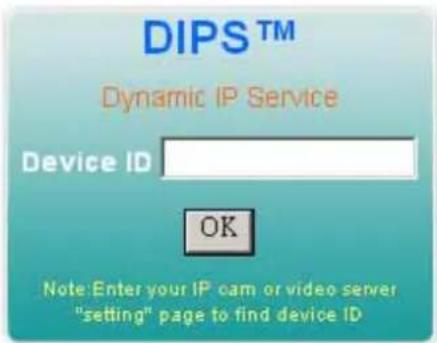
(4) Visiting our company's web site, you can find DIPS service page as below:
text_image
DIPS™ Dynamic IP Service Device ID OK Note: Enter your IP cam or video server "setting" page to find device IDEnter your Device Number and press "OK" button.
Then, a new web page will pop up and link to your device accordingly. You will see that DIPS is a much easier service than DDNS.
Device Title:
You can enter the name of this unit here. It's very useful to identify the specific device from multiple units. The information will be shown on IPWizard II once the device is found.
Software Version:
This information shows the software version of the device.
Network LED:
To turn on or off Network LED.
Power LED (Wireless LED):
To turn on or off Power LED (wireless LED if WLAN model).
Log:
User can check the system log information of the device, including the Main Info, Appended Info, Operator IP, and so on ...
Reload:
Click this button; user can refresh the log information of the device.
4.4.2 Date & Time
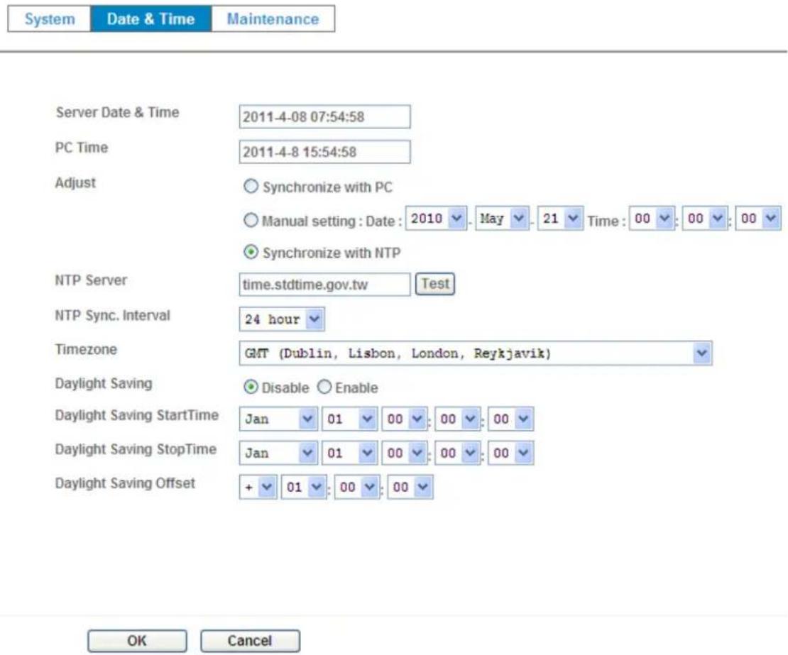
You can setup the device or make it synchronized with PC or remote NTP server. Also, you may select your time zone in order to synchronize time locally.
Server Date & Time:
Displays the date and time of the device.
PC Time:
Displays the date and time of the connected PC.
Adjust:
- Synchronize with PC:
Click this option to enable time synchronization with PC time.
- Manual setting:
Click this option to set time and date manually.
- Synchronize with NTP:
Click this option if you want to synchronize the device's date and time with those of time server called NTP server (Network Time Protocol).
NTP Server: Type the host name or IP address or domain name of the NTP server.
NTP sync. Interval: Select an interval between 1 and 23 hours at which you want to adjust the device's time referring to NTP server
Time zone:
Set the time difference from Greenwich Mean Time in the area where the device is installed.
Daylight Saving:
Disable or enable the daylight saving adjustment.
text_image
System Date & Time Maintenance Server Date & Time 2011-4-08 07:54:58 PC Time 2011-4-8 15:54:58 Adjust ○ Synchronize with PC ○ Manual setting : Date : 2010 ▼ . May ▼ . 21 ▼ Time : 00 ▼ . 00 ▼ . 00 ▼ ● Synchronize with NTP NTP Server time.stdtime.gov.tw Test NTP Sync. Interval 24 hour ▼ Timezone GMT (Dublin, Lisbon, London, Reykjavik) ▼ Daylight Saving ● Disable ○ Enable Daylight Saving StartTime Jan ▼ 01 ▼ 00 ▼ . 00 ▼ . 00 ▼ Daylight Saving StopTime Jan ▼ 01 ▼ 00 ▼ . 00 ▼ . 00 ▼ Daylight Saving Offset + ▼ 01 ▼ . 00 ▼ . 00 ▼ OK Cancel4.4.3 Maintenance
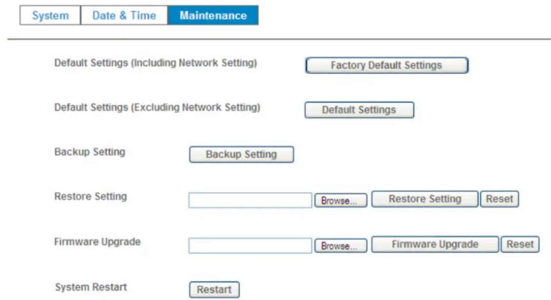
Hard Factory Default (Include the network setting):
Recall the device hard factory default settings. Note that click this button will reset all device's parameters to the factory settings (including the IP address).
Factory Default (Except the network setting):
The unit is restarted and most current settings are reset to factory default values. This action will not reset the network setting.
Backup Setting:
To take a backup of all of the parameters, click this button. If necessary, it will then be possible to return to the previous settings, if settings are changed and there is unexpected behavior.
Restore Setting:
Click the "Browse" button to locate the saved backup file and then click the "Restore Setting" button. The settings will be restored to the previous configuration.
text_image
System Date & Time Maintenance Default Settings (Including Network Setting) Factory Default Settings Default Settings (Excluding Network Setting) Default Settings Backup Setting Backup Setting Restore Setting Browse... Restore Setting Reset Firmware Upgrade Browse... Firmware Upgrade Reset System Restart RestartFirmware Upgrade:
The device supports new firmware upgrade (the software that controls the operation in the device). Please contact your dealer for the latest version if necessary.
Download the latest firmware file from our website or your dealer. Unzip this firmware file to binary file and store it into your PC. Then follow the steps as bellows carefully:
- Close all other application programs which are not necessary for firmware update.
- Make sure that only you access this device while firmware updating.
- Disable Motion Detection function.
- Click "Browse" button. Select the Firmware binary file.
(Note that it must make sure that the Firmware only applies to this device, once update, it will be burned into FLASH ROM of system.)
- Once the firmware file was selected, click "Firmware Upgrade" button.
- The upgrade progress information will be displayed. Once the uploading process completed, the device will reboot the system automatically.
- Please wait for timer countdown, and then you can use IPWizard II to search the device again.
Warning!!! The download firmware procedure cannot be interrupted. If the power and/or network connection are broken during the download procedure, it might possibly cause serious damage to the device.
Strongly suggest that DO NOT upgrade firmware via Wireless LAN due to high error rate possibly and don't allow any other clients to access this unit during updating procedure.
Be aware that you should not turn off the power during updating the firmware and wait for finish message.
Furthermore, the firmware upgrade procedure always is risk and do not try to upgrade new firmware if it's not necessary.
System Restart:
The device is restarted without changing any of the network settings. It means the IP address of the device will not change after firmware upgrade.
4.5 Video – Configure Profile
This device provides 2 modes of video profile. The first one is Mega-Pixel mode which supports video resolution up to Mega-pixel. However the maximum frame rate of this mode is up to 15fps only. The second one is VGA mode which supports video resolution up to VGA but frame rate can be up to 30fps. User only can select either Mega-pixel or VGA mode to operate the camera. Switching Mega-pixel and VGA, the device will take time to reboot system.
4.5.1 Common

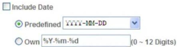
Text Overlay Setting
text_image
Include Date Predefined YYYY-MM-DD Own %Y-%m-%d (0 ~ 12 Digits)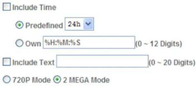
text_image
Include Time ● Predefined 24h ○ Own %H:%M:%S (0 ~ 12 Digits) □ Include Text (0 ~ 20 Digits) ○ 720P Mode ● 2 MEGA ModeVideo Profile

Text Overlay Setting:
There are some important information can be embedded into image, including date, time, and/or text.
Video Profile:
User can only choose either 720P or 2 Mega modes. The 720P mode can serve H.264 and JPEG streams up to 1280x720 resolution simultaneously. On the other hand, 2 Mega mode, it can streams up to 1600x1200 resolution simultaneously.
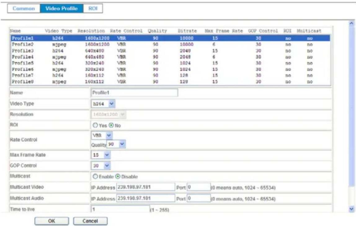
4.5.2 Video Profile
text_image
Common Video Profile ROI Name Video Type Resolution Rate Control Quality Bitrate Max Frame Rate GOP Control ROI Multicast Profile1 h264 1600x1200 VBR 90 10000 15 30 no no Profile2 mjpeg 1600x1200 VBR 90 10000 6 30 no no Profile3 h264 640x480 VBR 90 2048 15 30 no no Profile4 mjpeg 640x480 VBR 90 2048 6 30 no no Profile5 h264 320x240 VBR 90 1024 15 30 no no Profile6 mjpeg 320x240 VBR 90 1024 15 30 no no Profile7 h264 160x112 VBR 90 128 15 30 no no Profile8 mjpeg 160x112 VBR 90 128 15 30 no no Name Profile1 Video Type h264 Resolution 1600x1200 ROI Yes No Rate Control VBR Quality 90 Max Frame Rate 15 GOP Control 30 Multicast Enable Disable Multicast Video IP Address 239.198.97.181 Port 0 (0 means auto, 1024 - 65534) Multicast Audio IP Address 239.198.97.181 Port 0 (0 means auto, 1024 - 65534) Time to live 1 (1 - 255) OK CancelName:
Assign a name to the selected profile.
Video Type:
Video codec of the selected video profile.
Resolution:
Resolution of the selected video profile.
ROI:
Assign the selected profile as a ROI stream or not.
Rate Control:
Defines the rate control method of this profile. There are four options: Constant Bit Rate (CBR), Variable Bit Rate (VBR), Enhanced Constant Bit Rate (ECBR), and Enhanced Variable Bit Rate (EVBR).
For CBR, the video bit rate is between low to high bandwidth based on different resolutions. User can set the desired bit rate to match the limitation of bandwidth.
For VBR, user should choose the quality level to set the video quality rather than bit rate. The quality level is between 1 and 100. The higher value can reach the better quality but of course will consume higher bandwidth.
For ECBR, the video bitrate is based on normal CBR mode. However, the target bitrate can be increased to max target bitrate while lots of motion in video. The max target bitrate will keep a pre-defined time period and then back to normal CBR bitrate.
For EVBR, the video bitrate is based on normal VBR mode. However, the target bitrate can be increased to max target bitrate while lots of motion in video. The max target bitrate will keep a pre-defined time period and then back to normal VBR mode.
Max Frame Rate:
Defines the targeted frame rate of this profile. For example, set the frame rate to 15 fps, then the image will be updated for 15 frames per second as possible. User need to set reasonable max frame rate versus video quality under the limited bandwidth.
GOP Control:
Defines the Intra/Inter-frame (I/P) ratio of this profile. For example, set the GOP to 30, then the video stream will have one Intra-frame every 30 frames.
4.5.3 ROI
ROI means Region of Interest. Use this page to specify ROI window which ROI is QVGA resolution.
Common
Video Profile
ROI
natural_image
Interior view of a modern office with purple and white desks, no visible text or symbols
4.6 Audio – Audio Parameters
4.6.1 Setting
Setting
Audio
Mute While PT
Audio Mode
Input Gain
Output Gain

Disable

Enable

Disable

Enable

Simplex

Full duplex


Audio:
To enable or disable audio function
Mute While PT:
Mute the audio while pan and/or tilt motion
Audio Mode:
To select Simplex or Full duplex (2-way audio) mode
Input Gain:
To adjust gain of input audio
Output Gain:
To adjust gain of output audio
4.6.2 Manage User Name, Password and Login Privilege
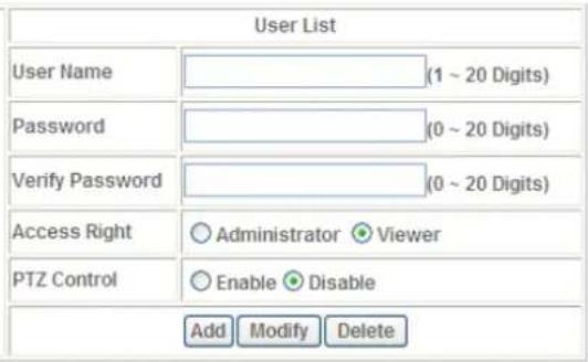
Use this menu to add, update, or remove the usernames and passwords of the Administrator and viewer.
Setting
Viewer Login

Anonymous

Only users in database
Save
| User Name | Access Right | PTZ Control |
| admin | administrator | yes |
text_image
User List User Name (1 ~ 20 Digits) Password (0 ~ 20 Digits) Verify Password (0 ~ 20 Digits) Access Right ○ Administrator ○ Viewer PTZ Control ○ Enable ○ Disable Add Modify DeleteViewer login:
Select "Anonymous" to allow any one viewing the video once connected. Otherwise, only users in database can view the video after login.
Access Right:
Administrator can access every function in this device. However, Viewers only can view the video and access limited function.
PTZ Control:
Authorize this user to control PTZ function or not.
Add, update, and remove of Users account:
Manage the user's account of viewer user.
4.6.3 E-Mail
You may setup SMTP mail parameters for further operation of Event Schedule. That's, if users want to send the alarm message out, it will need to configure parameters here and also add at least one event schedule to enable event triggering.
Setting
SMTP Server
SMTP Port
SSL
SMTP Authentication
Authentication User Name
Authentication Password
E-mail From
E-mail To
E-mail Subject



Disable

Enable

Disable

Enable





(< 129 Digits)
(1\~65535)
(< 65 Digits)
(< 22 Digits)
(< 129 Digits)
(< 129 Digits)
(< 65 Digits)
OK
Cancel
SMTP Server:
Type the SMTP server name or the IP address of the SMTP server.
Test:
Send a test mail to mail server to check this account is available or not.
SMTP Port:
Set port number of SMTP service.
SSL:
Enable SSL function or not.
SMTP Authentication:
Select the authentication required when you send an e-mail.
Disable: if no authentication is required when an e-mail is sent.
Enable: if authentication is required when an e-mail is sent.
Authentication User name:
Type the user name for the SMTP server if Authentication is Enable.
Authentication Password:
Type the password for the SMTP server if Authentication is Enable.
E-mail To:
Type the receiver's e-mail address.
E-mail From:
Type the sender's E-mail address. This address is used for reply e-mails.
E-mail Subject:
Type the subject/title of the e-mail.
4.6.4 Object Detection
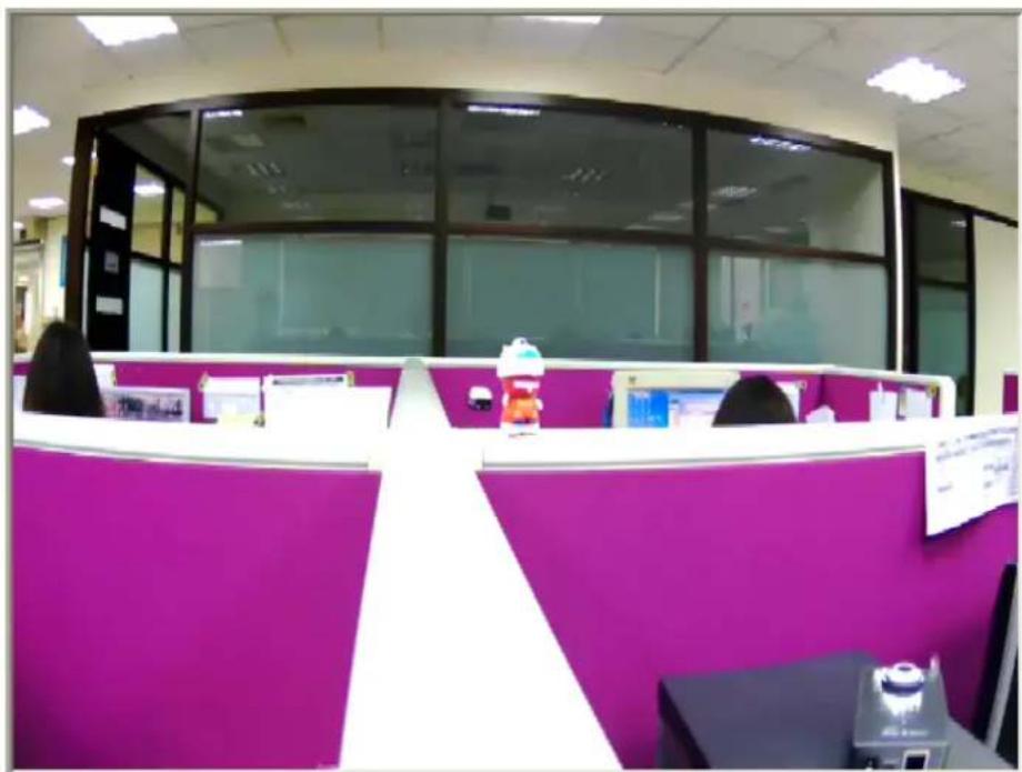
Use this menu to specify motion detection window 1 to window 10 and set the conditions for detection while observing a captured image.
natural_image
Interior view of a modern office cubicle with purple and white panels, no visible text or symbols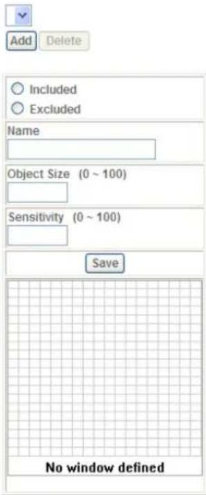
text_image
Add Delete Included Excluded Name Object Size (0 ~ 100) Sensitivity (0 ~ 100) Save No window definedAdd and Del:
To add or delete the motion windows. User can specify up to 10 Included and/or Excluded windows to monitor the video captured by this device. By dragging mouse on the image, you can change the position and size of the selected motion window accordingly.
Included or Excluded Window:
These windows can be specified as Included or Excluded type.
Included windows target specific areas within the whole video image
Excluded windows define areas within an Include window that should be ignored (areas outside Include windows are automatically ignored)
Name:
Name of the specified motion window.
Object Size:
Defines the object size of motion detection. The higher object size will only larger objects trigger motion detection. The lower object size will even small objects trigger motion detection too. Generally speaking, the smaller size will be easier to trigger event.
Sensitivity
Defines the sensitivity value of motion detection. The higher value will be more sensitivity.
4.6.5 Storage – Status and Configuration of SD card
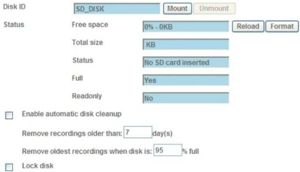
This page shows the status of attached SD card. You may setup related parameters to manage the attached SD card also.
SD Card
text_image
Disk ID SD_DISK Mount Unmount Status Free space 0% - 0KB Reload Format Total size KB Status No SD card inserted Full Yes Readonly No Enable automatic disk cleanup Remove recordings older than: 7 day(s) Remove oldest recordings when disk is: 95 % full Lock diskEnable automatic disk cleanup:
Delete old recorded files while the conditions are reached as below.
Remove recordings order than:
Delete old files by days.
Remove oldest recordings when disk is:
Delete old files by left capacity.
4.6.6 Recording List- Files List inside SD Card
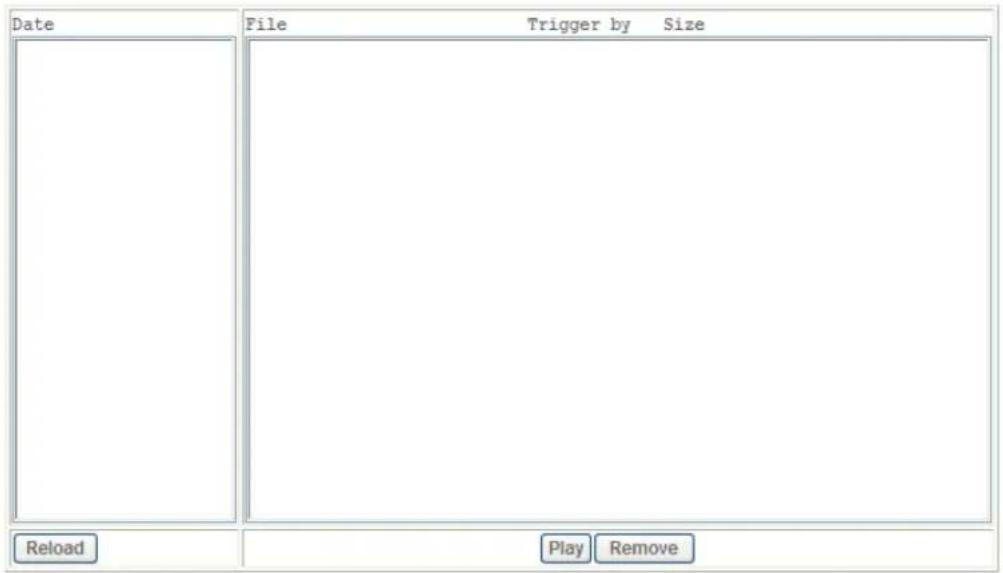
This page shows the files list information. User may play or delete the selected file.
Recording List
text_image
Date File Trigger by Size Reload Play Remove4.6.7 Event Sever
FTP Server •
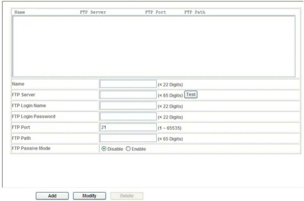
You may setup FTP parameters for further operation of Event Schedule. That's, if users want to send the alarm message to an FTP server, it will need to configure parameters here and also add at least one event schedule to enable event triggering as SMTP.
FTP Server TCP Server HTTP Server SAMBA Server
text_image
Name FTP Server FTP Port FTP Path Name (< 22 Digits) FTP Server (< 65 Digits) Test FTP Login Name (< 22 Digits) FTP Login Password (< 22 Digits) FTP Port 21 (1 ~ 65535) FTP Path (< 65 Digits) FTP Passive Mode Disable Enable Add Modify DeleteName:
User can specify multiple FTP paths as wish. Therefore, user needs to specify a name for each FTP setting.
FTP Server:
Type the server name or the IP address of the FTP server.
Test:
Check the FTP server whether this account is available or not.
FTP Login name:
Type the user name for the FTP server.
FTP Login Password:
Type the password for the FTP server.
FTP Port:
Set port number of FTP service.
FTP Path:
Set working directory path of FTP server.
FTP Passive Mode:
Select passive or active mode connecting to FTP server.
TCP Server •
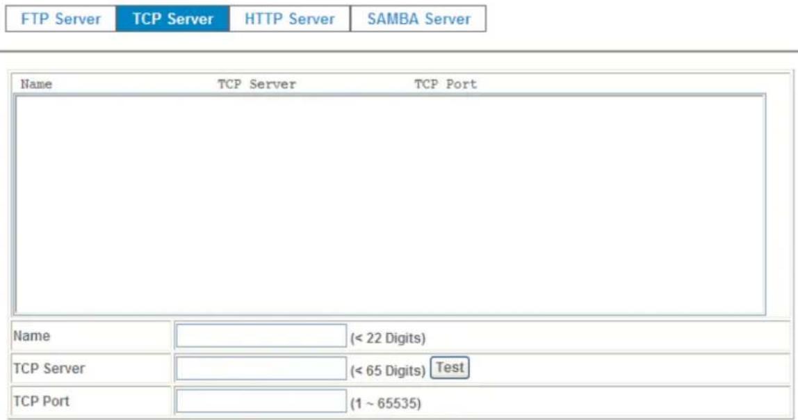
In addition to send video file to FTP server, the device also can send event message to specified TCP server.
text_image
FTP Server TCP Server HTTP Server SAMBA Server Name TCP Server TCP Port Name (< 22 Digits) TCP Server (< 65 Digits) Test TCP Port (1 ~ 65535)Name:
User can specify multiple TCP servers as wish. Therefore, user needs to specify a name for each TCP server setting.
TCP Server:
Type the server name or the IP address of the TCP server.
TCP Port:
Set port number of TCP server.
HTTP Server •
The device also can send event message to specified HTTP server.
| FTP Server | TCP Server | HTTP Server | SAMBA Server |
| Name | HTTP Server | Proxy Address |
| Name | (< 22 Digits) | |
| URL | http:// | (< 129 Digits) Test |
| HTTP Login Name | (< 22 Digits) | |
| HTTP Login Password | (< 22 Digits) | |
| Proxy Address | (< 129 Digits) | |
| Proxy Login Name | (< 22 Digits) | |
| Proxy Login Password | (< 22 Digits) | |
| Proxy Port | (1 ~ 65535) | |
Name:
User can specify multiple HTTP servers as wish. Therefore, user needs to specify a name for each HTTP server setting.
URL:
Type the server name or the IP address of the HTTP server.
Test:
Check the HTTP server whether it is available or not.
HTTP Login name:
Type the user name for the HTTP server.
HTTP Login Password:
Type the password for the HTTP server.
Proxy Address:
Type the server name or the IP address of the HTTP Proxy.
Proxy Login name:
Type the user name for the HTTP Proxy.
Proxy Login Password:
Type the password for the HTTP Proxy.
Proxy Port:
Set port number of Proxy.
SAMBA Server •
The device also can send video stream to specified SAMBA server.

User can specify multiple HTTP servers as wish. Therefore, user needs to specify a name for each HTTP server setting.
SAMBA Server:
Type the server name or the IP address of the SAMBA server.
Test:
Check the SAMBA server whether this account is available or not.
SAMBA Login name:
Type the user name for the SAMBA server.
Type the password for the SAMBA server.
SAMBA Path:
Set working directory path of SAMBA server.
4.6.8 Event Schedule
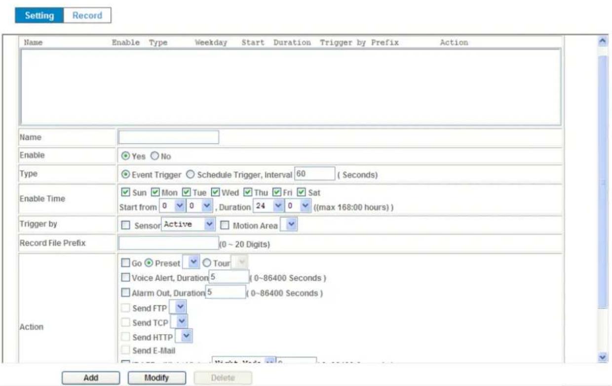
This menu is used to specify the schedule of Event or Schedule Trigger and activate the some actions provided by this device. Where the Schedule Trigger will be activated by user-define interval without event happened.
text_image
Setting Record Name Enable Type Weekday Start Duration Trigger by Prefix Action Name Enable Yes No Type Event Trigger Schedule Trigger, Interval 60 (Seconds) Enable Time Sun Mon Tue Wed Thu Fri Sat Start from 0 0 , Duration 24 0 ((max 168:00 hours)) Trigger by Sensor Active Motion Area Record File Prefix (0 ~ 20 Digits) Action Go Preset Tour Voice Alert, Duration 5 (0~86400 Seconds) Alarm Out, Duration 5 (0~86400 Seconds) Send FTP Send TCP Send HTTP Send E-Mail Add Modify DeleteName:
Name of the Event or Schedule.
Enable:
Enable or disable this Event or Schedule.
Type:
Event trigger or Schedule trigger.
Enable Time:
Define the feasible time slot.
Trigger by:
Select the triggered sources.
Action:
Define the actions once event triggered.
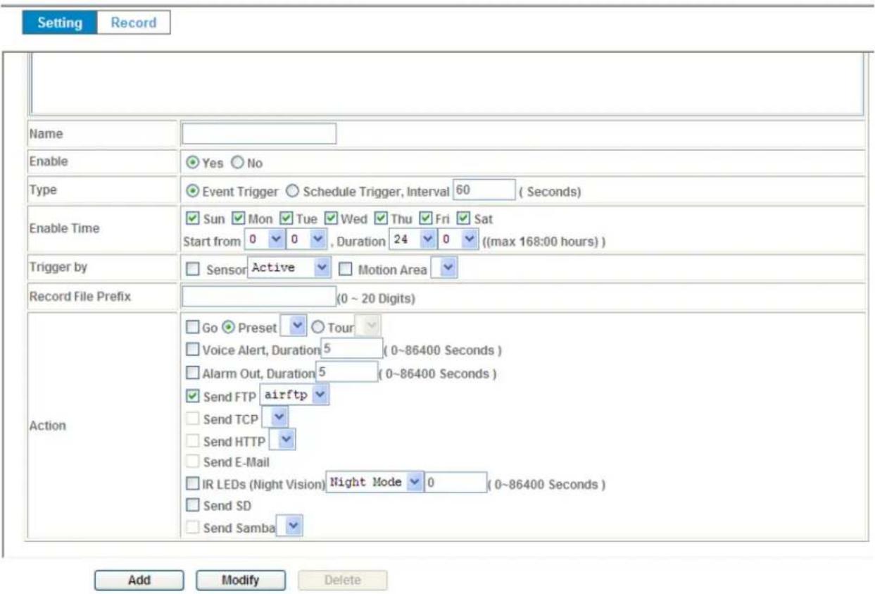
Example 1:
Send file to FTP server by motion triggered always:
- Select event trigger
- Enable time: start from 00:00 to 24:00 every day
- Trigger by: Motion Area (Added in Object Detection page)
- Action : Send FTP (Add in Event Server -> FTP Server page)
text_image
Setting Record Name Enable Yes No Type Event Trigger Schedule Trigger, Interval 60 (Seconds) Enable Time Sun Mon Tue Wed Thu Fri Sat Start from 0 0 , Duration 24 0 ((max 168:00 hours)) Trigger by Sensor Active Motion Area Record File Prefix (0 ~ 20 Digits) Action Go Preset Tour Voice Alert, Duration 5 (0~86400 Seconds) Alarm Out, Duration 5 (0~86400 Seconds) Send FTP airftp Send TCP Send HTTP Send E-Mail IR LEDs (Night Vision) Night Mode 0 (0~86400 Seconds) Send SD Send Samba Add Modify DeleteExample 2:
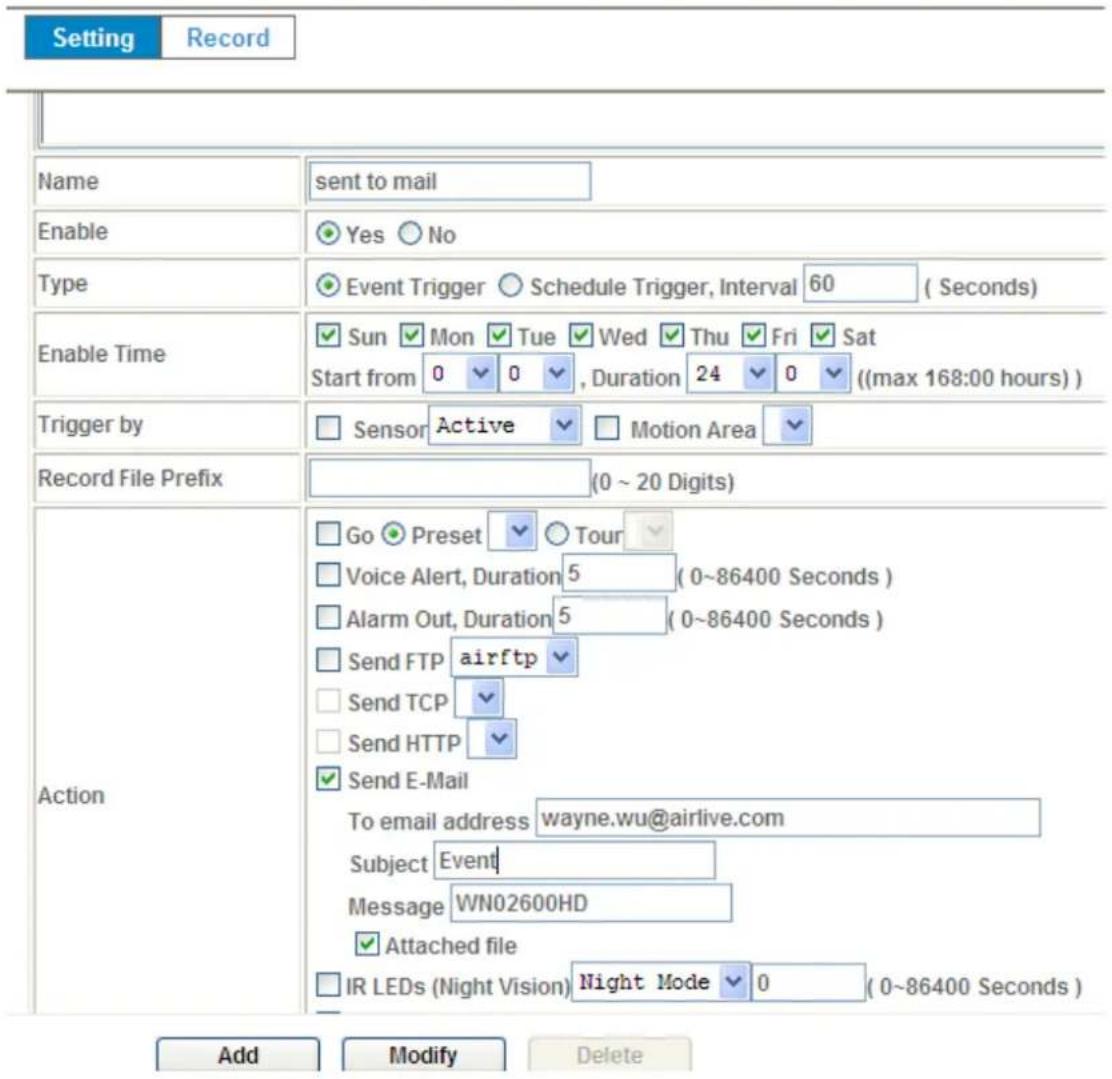
Send file to E-Mail server by motion triggered from Friday 18:00 to Saturday 06:00
- Select event trigger.
- Enable time: start from Friday 18:00 and keep work in 12 hous, so it will stop on Saturday 06:00.
-
Trigger by : Motion Area (Added in Object Detection page)
-
Action : Send e-mail (Add in E-Mail page)
i. To email address: You need to input the receiver email address.
ii. Subject: You could specify the email subject.
iii. Message: You could specify the email content.
text_image
Setting Record Name sent to mail Enable Yes No Type Event Trigger Schedule Trigger, Interval 60 (Seconds) Enable Time Sun Mon Tue Wed Thu Fri Sat Start from 0 0 , Duration 24 0 ((max 168:00 hours)) Trigger by Sensor Active Motion Area Record File Prefix (0 ~ 20 Digits) Action Go Preset Tour Voice Alert, Duration 5 (0~86400 Seconds) Alarm Out, Duration 5 (0~86400 Seconds) Send FTP airftp Send TCP Send HTTP Send E-Mail To email address wayne.wu@airlive.com Subject Event Message WN02600HD Attached file IR LEDs (Night Vision) Night Mode 0 (0~86400 Seconds) Add Modify DeleteExample 3:
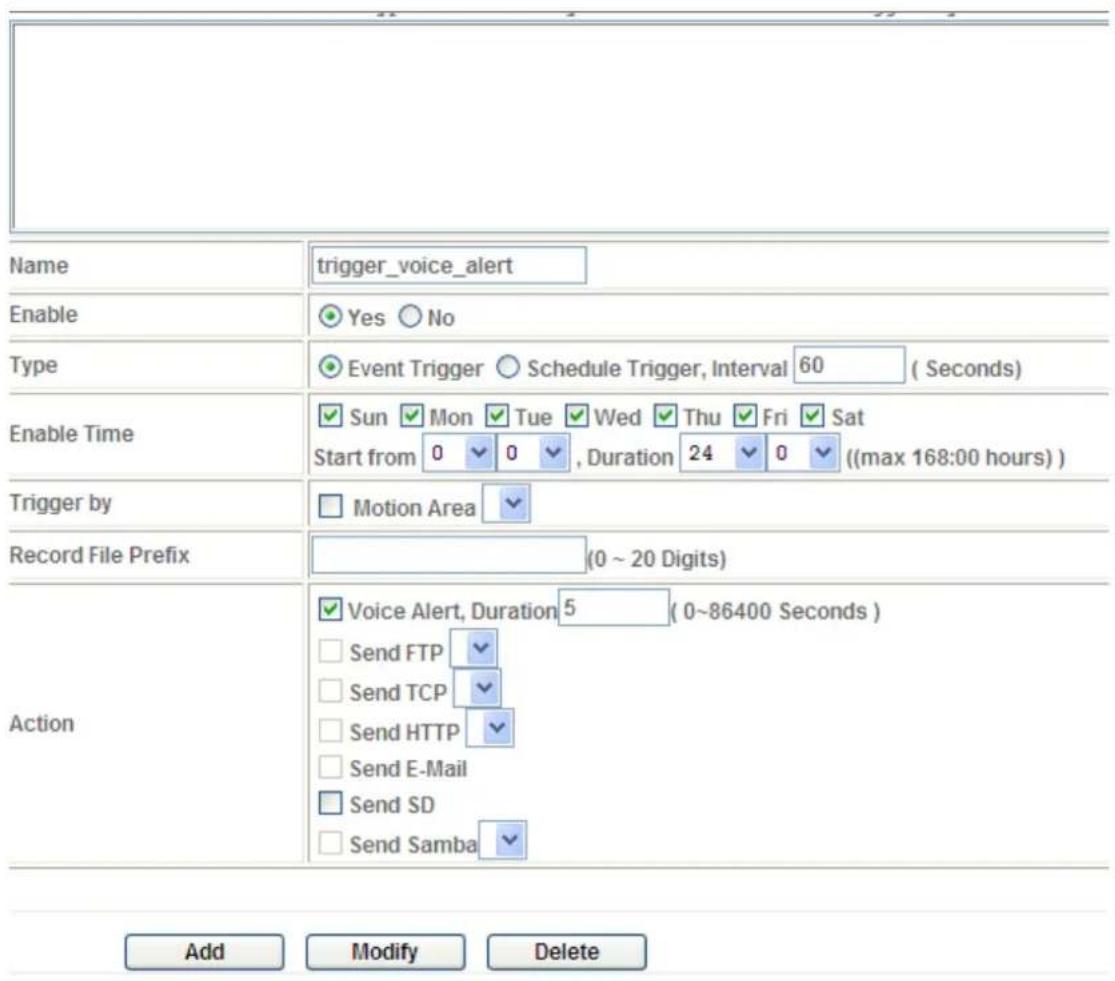
Enable Voice Alert every 10-minute during 18:00 to 24:00 from Monday to Friday.
- Type: Select schedule trigger and interval is 10-minute.
- Enable time: Select Monday to Friday, and set start time from 18:00 and keep work in 6 hours.
- Trigger by : You do not need to choose it, because this will be triggered every minute
- Action : Voice Alert
text_image
Name trigger_voice_alert Enable Yes No Type Event Trigger Schedule Trigger, Interval 60 (Seconds) Enable Time Sun Mon Tue Wed Thu Fri Sat Start from 0 0 , Duration 24 0 ((max 168:00 hours)) Trigger by Motion Area Record File Prefix (0 ~ 20 Digits) Action Voice Alert, Duration 5 (0~86400 Seconds) Send FTP Send TCP Send HTTP Send E-Mail Send SD Send Samba Add Modify DeleteRecord •
User can choose the type of record file for event or schedule application.
Record File Type
Record File Prefix
Pre Trigger Duration
Best Effort Duration
Max File Size
Profile1 h264 / 1600x1200
(0 \~ 20 Digits)
5 (0 \~ 20 Seconds)
30 (1 \~ 60 Seconds)
1024 (256 \~ 3072 Bytes)

Record File Type:
Choose JPEG, AVI-JPEG, or AVI-H.264 file format.
Record File Prefix:
Define the prefix of recorded filename.
JPEG Picture Numbers:
Define the picture numbers of JPEG to be sent out.
Pre-Trigger Duration:
Define the maximum duration of pre-alarm.
Post-Trigger Duration:
Define the maximum duration of post-alarm.
Max File Size:
Define the maximum buffer size of record file.
5
Troubleshooting & FAQ
5.1 Monitor the Image Section
| Question Answer or Resolution | |
| Features | |
| The video and audio codec is adopted in the device. | The device utilizes H.264, MPEG4 and JPEG triple compression to providing high quality images. Where H.264 and MPEG4 are standards for video compression and JPEG is a standard for image compression. The audio codec is defined as AMR for 3GPP and G.711/G.726 for RTSP streaming. |
| The maximum number of users access the device simultaneously. | The maximum number of users is limited to 20. However, it also depends on the total bandwidth accessed to this device from clients. The maximum data throughput of the device is around 20~25Mbps for UDP mode and 10Mbps for HTTP mode. Therefore, the actual number of connected clients is varying by streaming mode, settings of resolution, codec type, frame rate and bandwidth. Obviously, the performance of the each connected client will slow down when many users are logged on. |
| The device can be used outdoors or not. | The device is not weatherproof. It needs to be equipped with a weatherproof case for outdoors using. However, equipped with a weatherproof case might disable the audio function of the device. |
| Install this device | |
| Status LED does not light up. | · Check and confirm that the DC power adaptor, included in packaged, is used. Secure the power connector and re-power it on again. · If the problem is not solved, the device might be faulty. Contact your dealer for further help. |
| The network cabling is required for the device. | The device uses Category 5 UTP cable allowing 10 and/or 100 Base-T networking. |
| The device will be | If a firewall exists on the network, port 80 is open for |
| installed and work if a firewall exists on the network. | ordinary data communication. The HTTP port and RTSP port need to be opened on the firewall or NAT router. |
| The username and password for the first time or after factory default reset | Username =adminand password =airlive.Note that it's all case sensitivity. |
| Forgot the username and password | Follow the steps below.1.Restore the factory default setting by press pressing and holding down more than 3 seconds on the device.2.Reconfigure the device. |
| Forgot the IP address of the device. | Check IP address of device by using the IPWizard II program or by UPnP discovery. |
| IPWizard II program cannot find the device. | • Re-power the device if cannot find the unit within 1 minutes.• Do not connect device over a router. IPWizard II program cannot detect device over a router.• If IP address is not assigned to the PC which running IPWizard II program, then IPWizard II program cannot find device. Make sure that IP address is assigned to the PC properly.• Antivirus software on the PC might interfere with the setup program. Disable the firewall of the antivirus software during setting up this device.• Check the firewall setting of your PC or Notebook. |
| Internet Explorer does not seem to work well with the device | Make sure that your Internet Explorer is version 6.0 or later. If you are experiencing problems, try upgrading to the latest version of Microsoft's Internet Explorer from the Microsoft webpage. |
| IPWizard II program fails to save the network parameters. | • Network may have trouble. Confirm the parameters and connections of the device. |
| UPnP NAT Traversal | |
| Can not work with NAT router | • Maybe NAT router does not support UPnP function. Please check user's manual of router and turn on UPnP function.• Maybe UPnP function of NAT router is not compatibleto the IP camera. Please contact your dealer to get the approval routers list. |
| Some IP cameras are working but others are failed | · Maybe too many IP cameras have been installed on the LAN, and then NAT router is out of resource to support more cameras. You could turn off and on NAT router to clear out of date information inside router. |
| Access this device | |
| Cannot access the login page and other web pages of the Network Camera from Internet Explorer | · Maybe the IP Address of the Network Camera is already being used by another device or computer. To confirm this possible problem, disconnect the Network Camera from the network first, and then run the PING utility to check it out.· Maybe due to the network cable. Try correcting your network cable and configuration. Test the network interface by connecting a local computer to the Network Camera via a crossover cable.· Make sure the Internet connection and setting is ok.· Make sure enter the IP address of Internet Explorer is correct. If the Network Camera has a dynamic address, it may have changed since you last checked it.· Network congestion may prevent the web page appearing quickly. Wait for a while.The IP address and Subnet Mask of the PC and Network Camera must be in the same class of the private IP address on the LAN.· Make sure the http port used by the Network Camera, default=80, is forward to the Network Camera's private IP address.· The port number assigned in your Network Camera might not be available via Internet. Check your ISP for available port.· The proxy server may prevent you from connecting directly to the Network Camera, set up not to use the proxy server.· Confirm that Default Gateway address is correct.· The router needs Port Forwarding feature. Refer to your router's manual for details.· Packet Filtering of the router may prohibit access froman external network. Refer to your router's manual for details.• Access the Network Camera from the Internet with the global IP address of the router and port number of Network Camera.• Some routers reject the global IP address to access the Network Camera on the same LAN. Access with the private IP address and correct port number of Network Camera.• When you use DDNS, you need to set Default Gateway and DNS server address.• If it's not working after above procedure, reset Network Camera to default setting and installed it again.• If the problem is not solved, the Network Camera might be faulty. Contact your dealer for further help. |
| Image or video does not appear in the main page. | • The first time the PC connects to Network Camera, a pop-up Security Warning window will appear to download ActiveX Controls. When using Windows XP, or Vista, log on with an appropriate account that is authorized to install applications.• Network congestion may prevent the Image screen from appearing quickly. You may choose lower resolution to reduce the required bandwidth. |
| Check the device's ActiveX is installed on your computer | Go to C:\Windows\Downloaded Program Files and check to see if there is an entry for the file “IPCamera Control”. The status column should show “Installed”. If the file is not listed, make sure your Security Settings in Internet Explorer are configured properly and then try reloading the device's home page. Most likely, the ActiveX control did not download and install correctly. Check your Internet Explorer security settings and then close and restart Internet Explorer. Try to browse and log in again. |
| Internet Explorer displays the following message: “Your current security settings prohibitdownloading ActiveX controls”. | Setup the IE security settings or configure the individual settings to allow downloading and scripting of ActiveX controls. |
| The device work locally but not externally. | · Might be caused from the firewall protection. Check the Internet firewall with your system or network administrator. The firewall may need to have some settings changed in order for the device to be accessible outside your LAN.· Make sure that the device isn't conflicting with any other web server running on your LAN.· Check the configuration of the router settings allow the device to be accessed outside your local LAN.· Check the bandwidth of Internet connection. If the Internet bandwidth is lower than target bit rate, the video streaming will not work correctly. |
| The unreadable characters are displayed. | Use the operating system of the selected language. Set the Encoding or the Character Set of the selected language on the Internet Explorer. |
| Frame rate is slower than the setting. | · The traffic of the network and the object of the image affect the frame rate. The network congestion causes frame rate slower than the setting.· Check the bandwidth of Internet connection. If the Internet bandwidth is lower than target bit rate, the video streaming will not work correctly.· Ethernet switching hub can smooth the frame rate. |
| Blank screen or very slow video when audio is enabled. | · Your connection to the device does not have enough bandwidth to support a higher frame rate for the streamed image size. Try reducing the video streaming size to 160x120 or 320x240 and/or disabling audio.· Audio will consume 32 kbps. Disable audio to improve video. Your Internet connection may not have enough bandwidth to support streaming audio from the device. |
| Image Transfer on e-mail or FTP does not work. | · Default Gateway and DNS server address should be set up correctly.· If FTP does not work properly, ask your ISP or network administrator about the transferring mode of FTP server. |
| Pan/Tilt does not work. | · Click [Refresh] on the Internet Explorer when the |
| (including Click to Center and Preset Positioning) | communication stops with the device. The image will refresh.Other clients may be operating Pan/Tilt.Pan/Tilt operation has reached the end of corner. |
| Pan/Tilt does not work smoothly. | There may be a slight delay when you are using the Pan/Tilt feature in conjunction with streaming audio and video. If you find that there is a significant delay while panning or tilting the camera, try disabling the audio streaming and/or reducing the video streaming size. |
| Video quality of the device | |
| The focus on the Camera is bad. | The lens is dirty or dust is attached. Fingerprints, dust, stain, etc. on the lens can degrade the image quality. |
| The color of the image is poor or strange. | Adjust White Balance.To insure the images you are viewing are the best they can be, set the Display property setting (color quality) to 16bit at least and 24 bit or higher if possible within your computer.The configuration on the device image display is incorrect. You need to adjust the image related parameters such as brightness, contrast, hue and sharpness properly. |
| Image flickers.Wrong | power line frequency makes images flicker.Make sure the 50 or 60Hz format of your device.If the object is dark, the image will flicker. Make the condition around the Camera brighter. |
| Noisy images occur. | The video images might be noisy if the device is located in a very low light environment. Make the condition around the camera brighter or turn the White-light LED on. |
| Miscellaneous | |
| Cannot play the recorded ASF file | Have installed Microsoft®’s DirectX 9.0 or later and use the Windows Media Player 11.0 or later to play the AVI filed recorded by the Device. |
5.2 PING
The PING (stands for Packet Internet Groper) command is used to detect whether a specific IP address is accessible by sending a packet to the specific address and waiting for a reply. It's also a very useful tool to confirm the device installed or if the IP address conflicts with any other devices over the network.
If you want to make sure the IP address of the device, utilize the PING command as follows:
- Start a DOS window.
● Type ping x.x.x.x, where x.x.x.x is the IP address of the device.
The replies, as illustrated below, will provide an explanation to the problem.
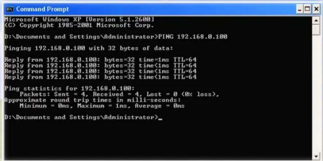
text_image
Microsoft Windows XP [Version 5.1.2600] (C) Copyright 1985-2001 Microsoft Corp. D:\Documents and Settings\Administrator>PING 192.168.0.100 Pinging 192.168.0.100 with 32 bytes of data: Reply from 192.168.0.100: bytes=32 time=1ms TTL=64 Reply from 192.168.0.100: bytes=32 time<1ms TTL=64 Reply from 192.168.0.100: bytes=32 time<1ms TTL=64 Reply from 192.168.0.100: bytes=32 time<1ms TTL=64 Ping statistics for 192.168.0.100: Packets: Sent = 4, Received = 4, Lost = 0 (0% loss), Approximate round trip times in milli-seconds: Minimum = 0ms, Maximum = 1ms, Average = 0ms D:\Documents and Settings\Administrator>If you want to detect any other devices conflicts with the IP address of Network Camera, also can utilize the PING command but you must disconnect the device from the network first.
5.3 Bandwidth Estimation
The frame rate of video transmitted from the device depends on connection bandwidth between client and server, video resolution, codec type, and quality setting of server. Here is a guideline to help you roughly estimate the bandwidth requirements form your device.
The required bandwidth depends on content of video source. The slow motion video will produce smaller bit rate generally and fast motion will produce higher bit rate vice versa. Actual results generated by the device may be varying.
| Image Resolution | Average range of data sizes for JPEG mode | Average bit rate for MPEG4 mode | Average bit rate for H.264 mode |
| 160 x 120 (QQVGA) | 3 ~ 6k byte per frame | 64kbps~256kbps @ 30fps | 32kbps~192kbps @ 30fps |
| 320 x 240 (QVGA) | 8 ~ 20k byte per frame | NA | 192kbps~512kbps @ 30fps |
| 640 x 480 (VGA) | 20 ~ 50K byte per frame | NA 384kbps~1536kbps @ 30fps | |
| 1280x720 (HD) | 100 ~ 200k byte per frame | NA | 512kbps~3076kbps @ 15fps |
| 1600x1200 (UXGA) | NA | 512kbps~3076kbps @ 15fps | |
Note: Audio streaming also takes bandwidth around 32kbps. Some xDSL/Cable modem upload speeds could not even reach up to 128 kbps. Thus, you may not be able to receive good quality video while also streaming audio on a 128 kbps or lower connection. Even though the upload speed is more than 128kbps, for optimal video performance, disabling audio streaming will get better video performance.
5.4 Specification Table
| Camera WN-200HD | |
| Image Device | 2 Mega-pixel image sensor |
| Effective Pixels | 1600 x 1200 pixels |
| Sensitivity | 1.0V/lux-sec |
| Signal to Noise | 42.3dB |
| Lens | 4.3mm |
| IP Module | |
| Video | |
| Video Encoder | H.264, MPEG4 and Motion JPEG simultaneously (Tri-encoders) |
| Video Profile | 9 profiles simultaneously |
| Frame Rate | Up to 30fps @ 1280x720 mode (HD mode) Up to 15fps @ 1600x1200 mode (2 Mega-pixel mode) |
| Image Setting | AE, AWB Noise reduction Color, brightness, sharpness, contrast Mirror/Flip Privacy Masks Text, time and date overlay |
| Streaming | Simultaneously multi-profile streaming Streaming over UDP, TCP, or HTTP M-JPEG streaming over HTTP (server push) Supports 3GPP mobile surveillance (MPEG4) Controllable frame rate and bandwidth Constant and variable bit rate (H.264) ROI |
| Audio | |
| Audio Encoder | RTSP: G.711 64kbps, G.726 32kbps 3GPP: AMR |
| Audio Streaming | One-way or two-way |
| Microphone | Built-in microphone |
| Audio Output | Adjustable audio output gain |
| Network | |
| Supported Protocols | IPv4, TCP, UDP, HTTP, HTTPS, SMTP, FTP, NTP, DNS, DDNS, DHCP, DIPS, ARP, Bonjour, UPnP, RTSP,RTP, RTCP, IGMP, PPPoE, 3GPP, Samba, ICMP |
| Security | Password protection, IP address filtering, HTTPS encrypted data transmission, user access log |
| Users | 20 simultaneous unicast users |
| Ethernet | 10/100M auto negotiation |
| Wireless | 11n |
| System Integration | |
| Application Programming Interface | ONVIFOpen API for software integrationSDK |
| Alarm Triggers | Intelligent video motion detection |
| Motion Detection | 10-zone video motion detection with included or excluded options |
| Alarm Events | File upload via FTP or emailNotification via email, HTTP, and TCPAudio alerting output |
| Video Buffer | Pre- and post- alarm buffering |
| General | |
| RAM | 128MB |
| ROM | 16MB |
| Power Supply | 12V DC external power adapter |
| Power Consumption | 3W |
| Connectors | RJ-45 10BaseT/100BaseTXDC power jackAudio outFactory default resetSD card |
| Indication LED | Green and orange LEDs |
| Operating Temperature | 0°C to 40°C (32°F to 104°F) |
| Operating Humidity | 20% ~ 80% (non-condensing) |
| Dimension | HxWxD:74.5 x 52.6 x 35..0 (mm) |
| Viewing System | |
| OS | Windows® XP, Vista, 7 |
| Browser | IE 6.0 or later, Firefox 2.0 or later, Safari |
| Cell Phone | With 3GPP player |
| Video Player | VLC, Quick Time, Real Player, Core Player |
| Software | |
| Search & Installation | IPWizard II |
| Bundled NVR Program | SecuGuard 64CH |
5.5 Configure Port Forwarding Manually
The device can be used with a router. If the device wants to be accessed from the WAN, its IP address needs to be setup as fixed IP address, also the port forwarding or Virtual Server function of router needs to be setup. This device supports UPnP traversal function. Therefore, user could use this feature to configure port forwarding of NAT router first. However, if user needs to configure port forwarding manually, please follow the steps as below:
Manually installing the device with a router on your network is an easy 3-step procedure as following:
(1) Assign a local/fixed IP address to your device
(2) Access the Router with Your Web browser
(3) Open/Configure Virtual Server Ports of Your Router
(1) Assign a local/fixed IP address to your device
The device must be assigned a local and fixed IP Address that allows it to be recognized by the router. Manually setup the device with a fixed IP address, for example, 192.168.1.100.
(2) Access the Router with Your Web browser
The following steps generally apply to any router that you have on your network. The D-Link DI-624 is used as an example to clarify the configuration process. Configure the initial settings of the router by following the steps outlined in the router's Quick Installation Guide.
If you have cable or DSL service, you will most likely have a dynamically assigned WAN IP Address. 'Dynamic' means that your router's WAN IP address can change from time to time depending on your ISP. A dynamic WAN IP Address identifies your router on the public network and allows it to access the Internet. To find out what your router's WAN IP Address is, go to the Status screen on your router and locate the WAN information for your router. As shown on the following page the WAN IP Address will be listed. This will be the address that you will need to type in your web browser to view your camera over the Internet. Be sure to uncheck the Reset IP address at next boot button at the top of the screen after modifying the IP address. Failure to do so will reset the IP address when you restart your computer.
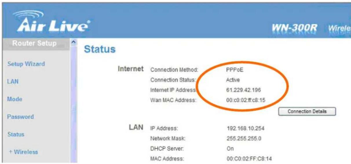
text_image
Air Live® WN-300R Wireless Router Setup Status Internet Connection Method: PPPoE Connection Status: Active Internet IP Address: 61.229.42.196 Wan MAC Address: 00:c0:02:ff:c8:15 Connection Details LAN IP Address: 192.168.10.254 Network Mask: 255.255.255.0 DHCP Server: On MAC Address: 00:c0:02:FF:c8:14Your WAN IP Address will be listed here.
Note: Because a dynamic WAN IP can change from time to time depending on your ISP, you may want to obtain a Static IP address from your ISP. A Static IP address is a fixed IP address that will not change over time and will be more convenient for you to use to access your camera from a remote location. If you could not get a Static IP address from your ISP, the DIPS™ or DDNS is a solution alternatively. Please refer to Appendix G for more information.
(3) Open/set Virtual Server Ports to enable remote image viewing
The firewall security features built into the router and most routers prevent users from accessing the video from the device over the Internet. The router connects to the Internet over a series of numbered ports. The ports normally used by the device are blocked from access over the Internet. Therefore, these ports need to be made accessible over the Internet. This is accomplished using the Virtual Server function on the router. The Virtual Server ports used by the camera must be opened through the router for remote access to your camera. Virtual Server is accessed by clicking on the Advanced tab of the router screen.
Follow these steps to configure your router's Virtual Server settings
- Click Enabled.
- Enter a unique name for each entry.
- Select Both under Protocol Type (TCP and UDP)
- Enter your camera's local IP Address (e.g., 192.168.1.100, for example) in the Private IP field.
- If you are using the default camera port settings, enter 80 into the Public and Private Port section, click Apply.
- Scheduling should be set to Always so that the camera images can be accessed at any time.
A check mark appearing before the entry name will indicate that the ports are enabled.
Important: Some ISPs block access to port 80. Be sure to check with your ISP so that you can open the appropriate ports accordingly. If your ISP does not pass traffic on port 80, you will need to change the port the camera uses from 80 to something else, such as 8080. Not all routers are the same, so refer to your user manual for specific instructions on how to open ports.
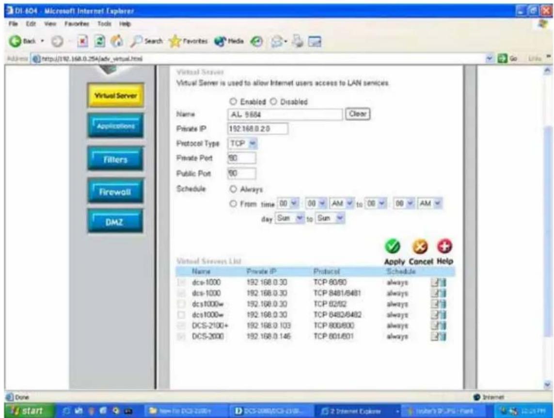
text_image
DI-804 - Microsoft Internet Explorer File Edit View Favorites Tools Help Back Search Favorites Media Address http://192.168.0.254/adv_virtual.html Virtual Server Virtual Server is used to allow Internet users access to LAN services. Enabled Disabled Name AL 9684 Clear Private IP 192.168.0.2.0 Protocol Type TCP Private Port 60 Public Port 60 Schedule Always From time 00 00 AM to 00 00 AM day Sun to Sun Apply Cancel Help Virtual Servers List Name Private IP Protocol Schedule dcs-1000 192.168.0.30 TCP 80/90 always dcs-1000 192.168.0.30 TCP 8481/8481 always dcs-1000w 192.168.0.30 TCP 82/92 always dcs-1000w 192.168.0.30 TCP 8482/8482 always DCS-2100+ 192.168.0.103 TCP 800/800 always DCS-2000 192.168.0.146 TCP 801/801 always Done Internet start DCS-2000DCS-2000DCS-2000DCS-2000DCS-2000DCS-2000DCS-2000DCS-2000DCS-2000DCS-2000DCS-2000DCS-2000DCS-2000DCS-2000DCS-2000DCSEnter valid ports in the Virtual Server section of your router. Please make sure to check the box on this line to enable settings. Then the device can be access from WAN by the router's WAN IP Address.
By now, you have finished your entire PC configuration for this device.
5.6 DDNS
1. Preface
If you have a Cable modem or xDSL, this is a great way to host your own Networked Device or other TCP/IP Service. Get your own domain like www.yourname.com, www.yourname.com.tw etc. (Note: This domain must be registered with Internic via registration authorities such as Network Solutions, DirectNIC, Register.com etc). Your domain name's dynamic IP address is automatically tracked by a DDNS server.
Host your own Networked Device and much more no matter what your computer's IP address may be and even if you have dialup, DSL or cable modem internet connection where your computer's IP address changes all the time!! DDNS service supports all top level domain names including but not limited to .com, .net, .org, .to, .uk etc.
2. Ethernet Network Environment
Normally, DDNS service is only necessary for the users that could only obtain dynamic IP addresses. As to the users that could obtain the static valid IP address, they do not usually have to apply the DDNS service. Before we decide if DDNS is necessary for the users, we have to check what kind of Ethernet network environment we have to install our Networked Device on.
(1) Environment of Fixed Valid IP Network
If users could obtain valid IP addresses, they could save the effort to apply DDNS service. Because the IP address in this environment is fixed, users could input the IP address or domain name of demo site directly in the IE browser.
(2) Environment of Dynamic IP Network
If users is under an environment of dynamic IP network (Dial-up xDSL), they have to apply a domain name in advance. Then apply DDNS service. Finally setup the necessary information of DDNS and PPPoE of the Networked Device in order to let the outside administrator be able to access through internet.
3. Application Steps—DDNS & Domain Name
(1). Visit the following web site: http://www.dyndns.org/
(2). Click "Account"
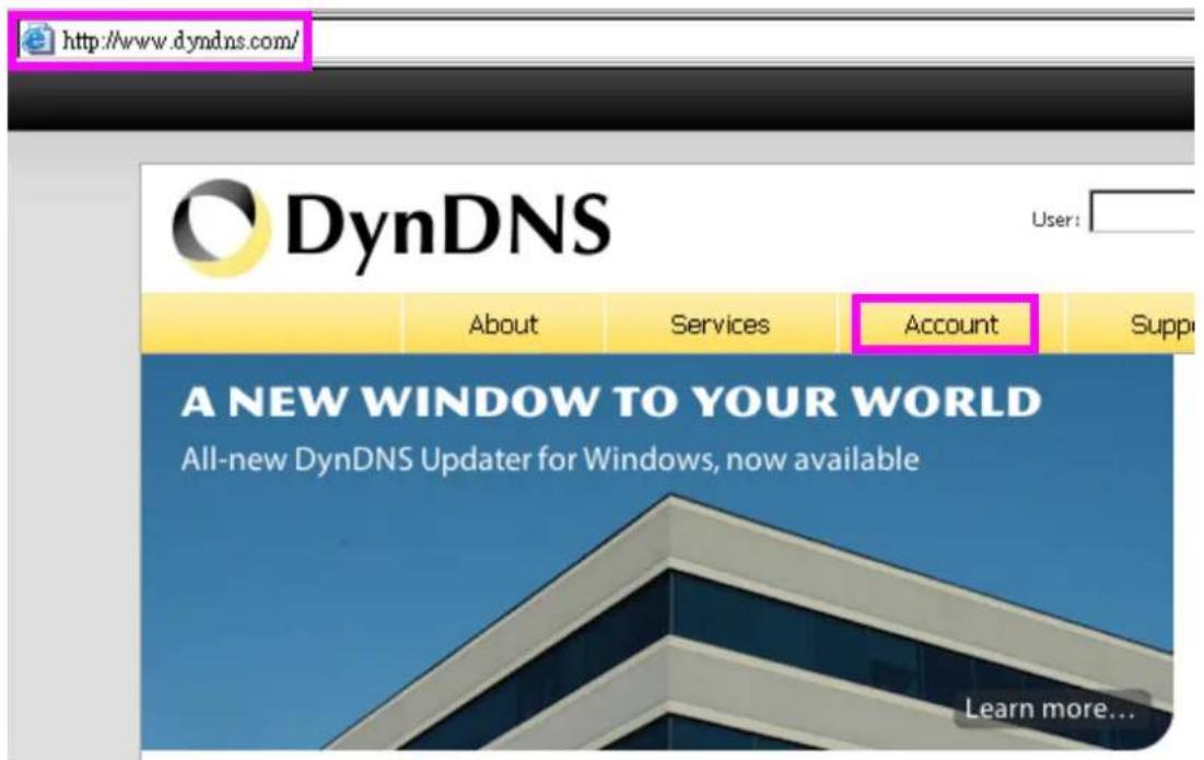
text_image
http://www.dyndns.com/ DynDNS User: About Services Account Suppl A NEW WINDOW TO YOUR WORLD All-new DynDNS Updater for Windows, now available Learn more...(3). After the columns show up at the left side, click "Create Account".
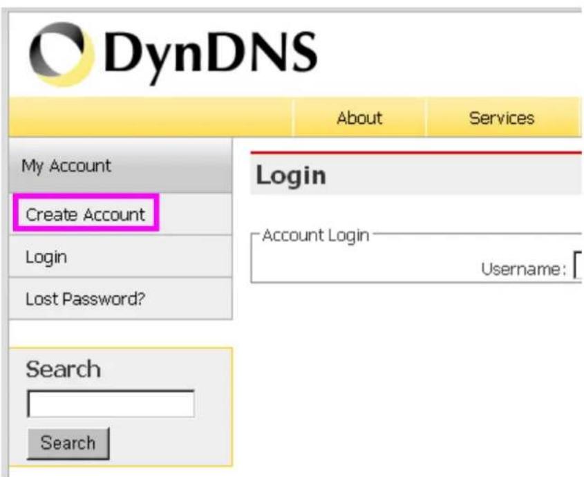
text_image
DynDNS About Services My Account Create Account Login Lost Password? Login Account Login Username: Search Search(4). Fill the application agreement and necessary information.
a. Username
b. E-mail address and confirmation
c. Password and confirmation
d. Submit all the input information and finish creating an account
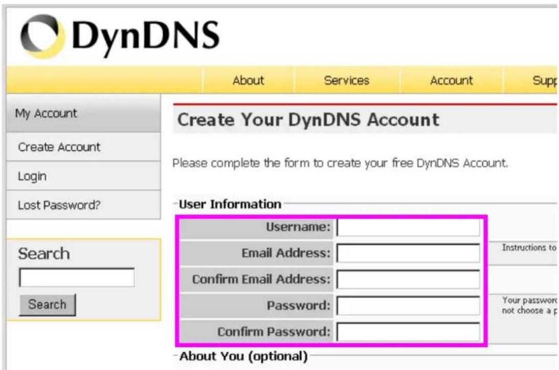
text_image
DynDNS About Services Account Supp My Account Create Account Login Lost Password? Create Your DynDNS Account Please complete the form to create your free DynDNS Account. User Information Username: Email Address: Confirm Email Address: Password: Confirm Password: Search Search Instructions to Your password not choose a p -About You (optional)Terms of Service
Please read the acceptable use policy (AUP) and accept it prior to creating your account. Also acknowledge that you may only have one (1) free account, and that creation of multiple free accounts will result in the deletion of all of your accounts.
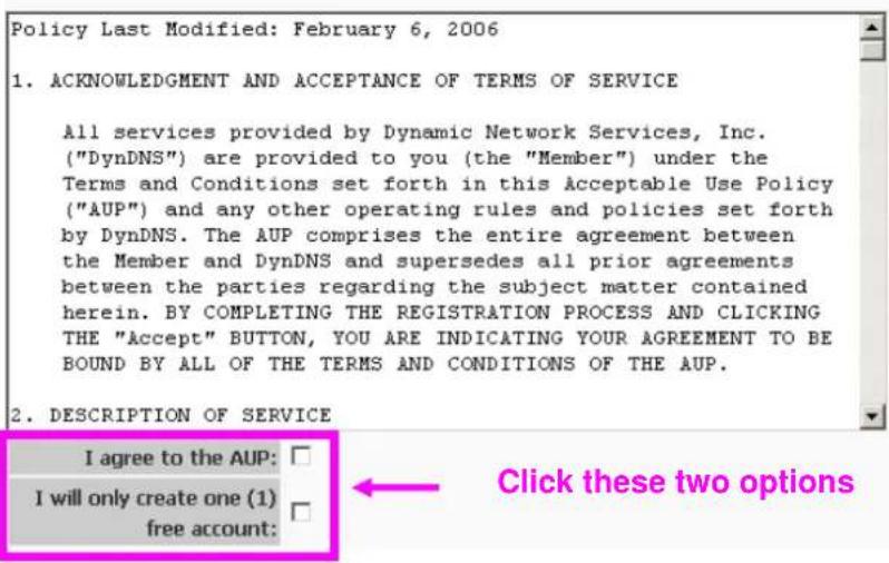
text_image
Policy Last Modified: February 6, 2006 1. ACKNOWLEDGMENT AND ACCEPTANCE OF TERMS OF SERVICE All services provided by Dynamic Network Services, Inc. ("DynDNS") are provided to you (the "Member") under the Terms and Conditions set forth in this Acceptable Use Policy ("AUP") and any other operating rules and policies set forth by DynDNS. The AUP comprises the entire agreement between the Member and DynDNS and supersedes all prior agreements between the parties regarding the subject matter contained herein. BY COMPLETING THE REGISTRATION PROCESS AND CLICKING THE "Accept" BUTTON, YOU ARE INDICATING YOUR AGREEMENT TO BE BOUND BY ALL OF THE TERMS AND CONDITIONS OF THE AUP. 2. DESCRIPTION OF SERVICE I agree to the AUP: I will only create one (1) free account: Click these two optionsNext Step
After you click "Create Account", we will create your account and send you an e-mail to the address you provided. Please follow the instructions in that e-mail to confirm your account. You will need to confirm your account within 48 hours or we will automatically delete your account. (This helps prevent unwanted robots on our systems)
Create Account
(5). Check your e-mail mailbox. There will be an e-mail with a title "Your DynDNS Account Information". Click the hyperlink address to confirm the DDNS service that you just applied. Then DDNS you applied activated.
Your DynDNS Account 'kkkkk' has been created. You need to visit the confirmation address below within 48 hours to complete the account creation process: Click to confirm
https://www.dyndns.com/account/confirm/oDDGDYN75qTJk_ICGba6vQ
Our basic service offerings are free, but they are supported by our paid services. See http://www.dyndns.com/services/ for a full listing of all of our available services.
If you did not sign up for this account, this will be the only communication you will receive. All non-confirmed accounts are automatically deleted after 48 hours, and no addresses are kept on file. We apologize for any inconvenience this correspondence may have caused, and we assure you that it was only sent at the request of someone visiting our site requesting an account.
Sincerely, The DynDNS Team
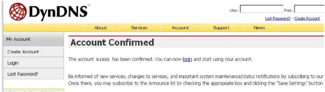
text_image
DynDNS® User: Pass: Lost Password? - Create Account About Services Account Support News My Account Create Account Login Lost Password? Account Confirmed The account is sick has been confirmed. You can now login and start using your account. Be informed of new services, changes to services, and important system maintenance/status notifications by subscribing to our Once there, you may subscribe to the Announce list by checking the appropriate box and clicking the "Save Settings" button.(6). Enter the web page http://www.dyndns.org/ again. Input your username and password that you just applied to login administration interface of DDNS server.
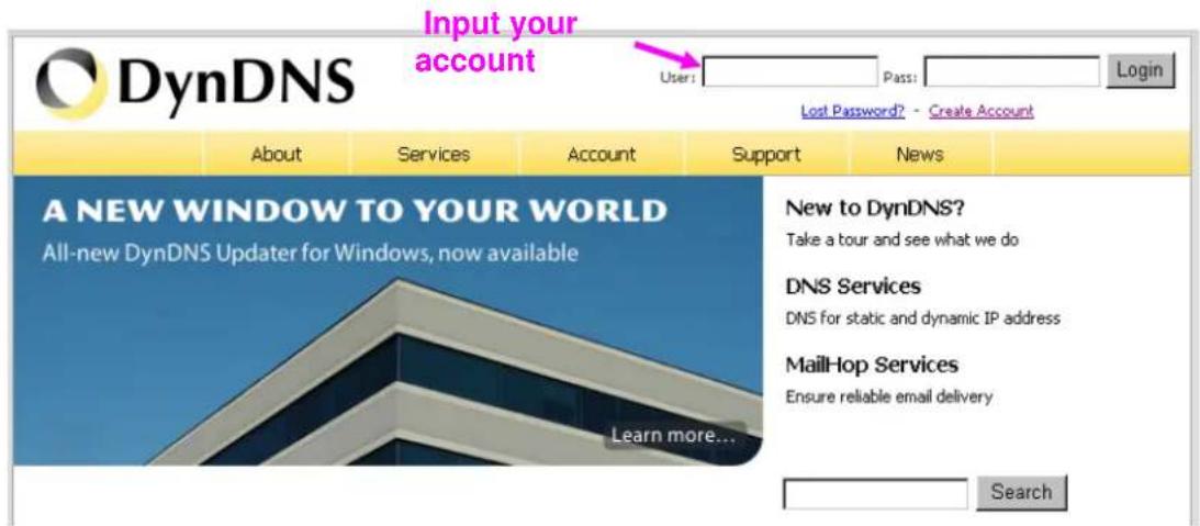
text_image
Input your account DynDNS User: Pass: Login Lost Password? - Create Account About Services Account Support News A NEW WINDOW TO YOUR WORLD All-new DynDNS Updater for Windows, now available Learn more... New to DynDNS? Take a tour and see what we do DNS Services DNS for static and dynamic IP address MailHop Services Ensure reliable email delivery Search(7). If the correct username and password are input, you can see the following picture at the top-right of the login page.
(8). Click the "Services".
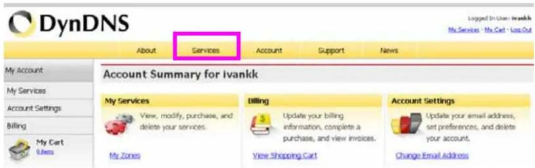
text_image
DynDNS About Services Account Support News My Account My Services Account Settings Billing My Cart 0.8mm Account Summary for ivankk My Services View, modify, purchase, and delete your services. My Zones Billing Update your billing information, complete a purchase, and view invoices. View Shopping Cart Account Settings Update your email address, set preferences, and delete your account. Change Email Address(9). Click the "Dynamic DNS".
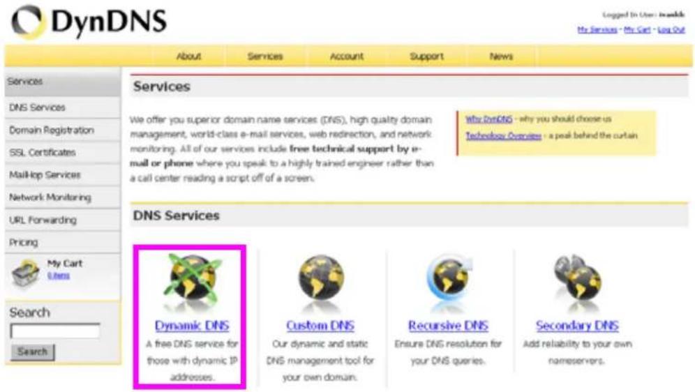
text_image
DynDNS About Services Account Support News Services DNS Services Domain Registration SSL Certificates Mail-Stop Services Network Monitoring URL Forwarding Pricing My Cart Users Search Search Services We offer you superior domain name services (DNS), high quality domain management, world-class e-mail services, web redirection, and network monitoring. All of our services include free technical support by email or phone where you speak to a highly trained engineer rather than a call center reading a script off of a screen. Why DnsDNS - why you should choose us Technology Devices - a peak behind the curtain DNS Services Dynamic DNS A free DNS service for those with dynamic IP addresses. Custom DNS Our dynamic and static DNS management tool for your own domain. Recursive DNS Ensure DNS resolution for your DNS queries. Secondary DNS Add reliability to your own nameservers.(10). Click the "Get Started".
Dynamic DNS
Dynamic DNS (DDNS) allows you to create a hostname that points to your dynamic IP or static IP address or URL. We also provide an update mechanism which makes the hostname work with your dynamic IP address. We continue to offer this service free to the Internet community as we have done so for nearly 10 years.
Capabilities and Features
• Get five (5) hostnames in 88 available domains for free.
- Create wildcard CNAME *.yourhost.dyndns.org for yourhost.dyndns.org.
- Forward web requests or mark host offline for maintenance or downtime.
- Configure MX records for flexible mail routing.
- Update host using ddns update clients for a wide variety of platforms.
- Modify DNS TTL values for fast propagation or reliable static IP caching.
- Deliver your DNS records to 5 DNS servers in 5 tier-1 datacenters around the globe.
• Query volume up to 648,000 queries/month
text_image
Get Started Manage Hosts
Our free industry-leading e-mail support is ready to help you setup your dynamic or static DNS so you can host a website, remotely connect to your machine, and run a mail server. We also offer other premium features with our Account Upgrade service.
(11). We could create a domain name without any charge at this step. First, we input the host name. (Pink No.1) Then we pick a domain that is easy to remember. (Pink No.2) The 3^rd step is to click “Offline Hostname” from Service Type. (Pink No.3) Finally, click the “Create Host” to submit the domain name information and finish DDNS application. (Pink No.4)
Add New Hostname
↑ Host Services
Note: You currently don't have Account Upgrades in your account. You cannot use some of our Host Service features. Please consider buying Account upgrade that make this form full-functional and will add several other features. Learn More...
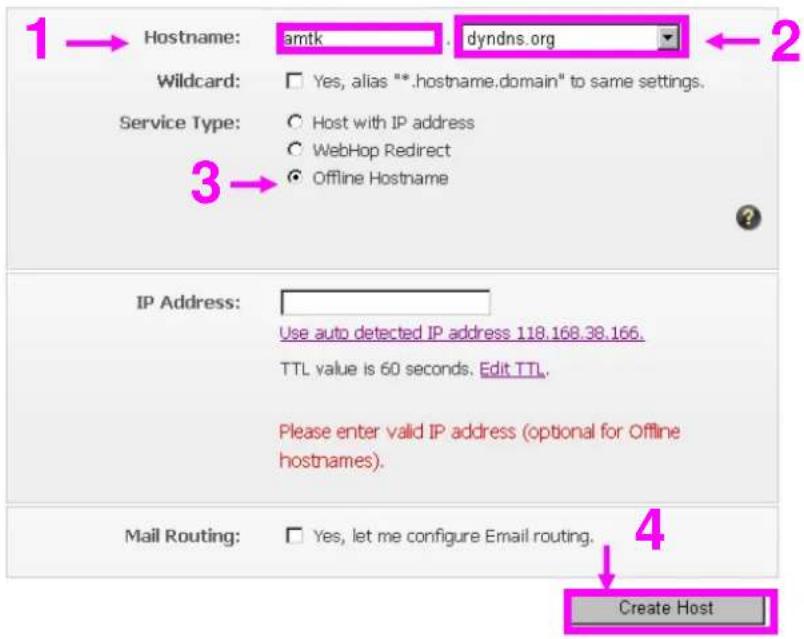
text_image
1 → Hostname: amtk dyndns.org ← 2 Wildcard: Yes, alias "*.hostname.domain" to same settings. Service Type: Host with IP address WebHop Redirect Offline Hostname 3 → IP Address: Use auto detected IP address 118.168.38.166. TTL value is 60 seconds. Edit TTL. Please enter valid IP address (optional for Offline hostnames). Mail Routing: Yes, let me configure Email routing. 4 Create Host4. Setup the DDNS and PPPoE of Networked Device
At last, users have to enter the web page of Networked Device and setup the necessary information of DDNS and PPPoE after the application of DDNS service. Please check the user manual to access the DDNS and PPPoE pages. After saving the modification, restart the device. Then the external users could browse the Networked Device by the input of their domain name.
5.7 Power Line Frequency
| COUNTRY | VOLTAGE | FREQUENCY | COMMENTS |
| Argentina | 220V 50 | Hz *Neutral and line | wires are reversed from that used in Australia and elsewhere. |
| Australia | 230V* 50 | Hz *Outlets typically | controlled by adjacent switch.Though nominal voltage has been officially changed to230V, 240V is within tolerances and commonly found. |
| Austria | 230V 50 | Hz | |
| Brazil | 110/220V* | 60 Hz *127V found | in states of Bahia, Paran?(including Curitiba), Rio de Janeiro, S 緌 Paulo and Minas Gerais (though 220V may be found in some hotels). Other areas are 220V only, with the exception of Fortaleza (240V). |
| Canada | 120V 60 | Hz | |
| China, People's Republic of | 220V | 50 | Hz |
| Finland | 230V | 50 | Hz |
| France | 230V | 50 | Hz |
| Germany | 230V 50 | Hz | |
| Hong Kong | 220V* | 50 | Hz |
| India | 230V | 50 | Hz |
| Italy | 230V | 50 | Hz |
| Japan | 100V 50 | 60 Hz* *Eastern Japan | Japan 50 Hz(Tokyo, Kawasaki, Sapporo, Yokohoma, and Sendai); Western Japan 60 Hz(Osaka, Kyoto, Nagoya, Hiroshima) |
| Malaysia | 240V 50 | Hz | |
| Netherlands | 230V 50 | Hz | |
| Portugal | 230V 50 | Hz | |
| Spain | 230V 50 | Hz | |
| Sweden | 230V 50 | Hz | |
| Switzerland | 230V | 50 | Hz |
| Taiwan | 110V 60 | Hz | |
| Thailand | 220V | 50 | Hz |
| United Kingdom | 230V* 50 | Hz *Outlets typically | controlled by adjacent switch.Though nominal voltage has been officially changed to 230V, 240V is within tolerances and commonly found. |
| United States of America | 120V 60 | Hz |
5.8 3GPP Table
To use the 3GPP function, in addition to previous section, you might need more information or configuration to make this function work.
Note that to use the 3GPP function, it strongly recommends to install the Networked Device with a public and fixed IP address without any firewall protection.
RTSP Port:
Port 554 is the default for RTSP service. However, sometimes, some service providers change this port number for some reasons. If so, user needs to change this port accordingly.
Dialing procedure:
- Choose a verified player (PacketVideo or Realplayer currently)
- Use the following URL to access:
rtsp://host/mpeg4/media.3gp
Where host is the host name or IP address of the camera.
Compatible 3G mobile phone:
Please contact your dealer to get the approved list of compatible 3G phone.
5.9 UPnP
Use the following steps to enable UPnP settings only if your operating system of PC is running Windows XP.
Go to Start > Settings.
Click Control Panel
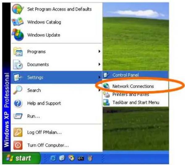
text_image
Set Program Access and Defaults Windows Catalog Windows Update Programs Documents Settings Search Help and Support Run... Log Off PMalan... Turn Off Computer... Control Panel Network Connections Printers and Faxes Taskbar and Start Menu startClick Add or Remove Programs
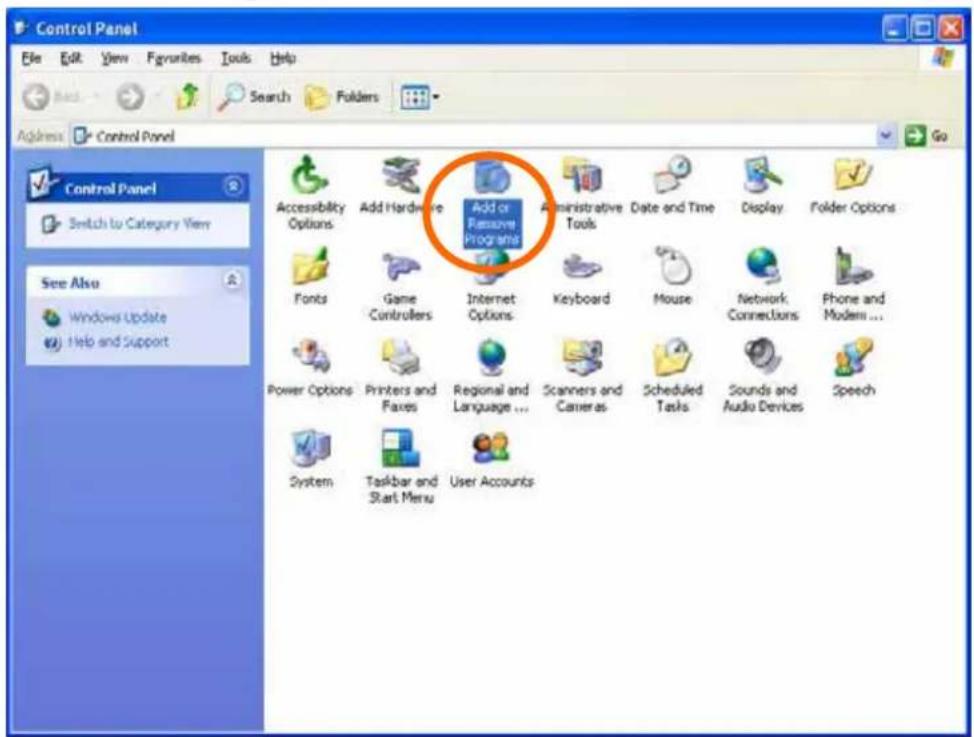
text_image
Control Panel File Edit View Favorites Tools Help Back Search Folders Address Control Panel Control Panel Switch to Category View See Also Windows Update Help and Support Accessibility Options Add Hardware Add or Remove Programs Administrative Tools Date and Time Display Folder Options Fonts Game Controllers Internet Options Keyboard Mouse Network Connections Phone and Modem ... Power Options Printers and Fixes Regional and Language ... Scanners and Cameras Scheduled Tasks Sounds and Audio Devices Speech System Taskbar and Start Menu User AccountsClick Add/Remove Windows Components
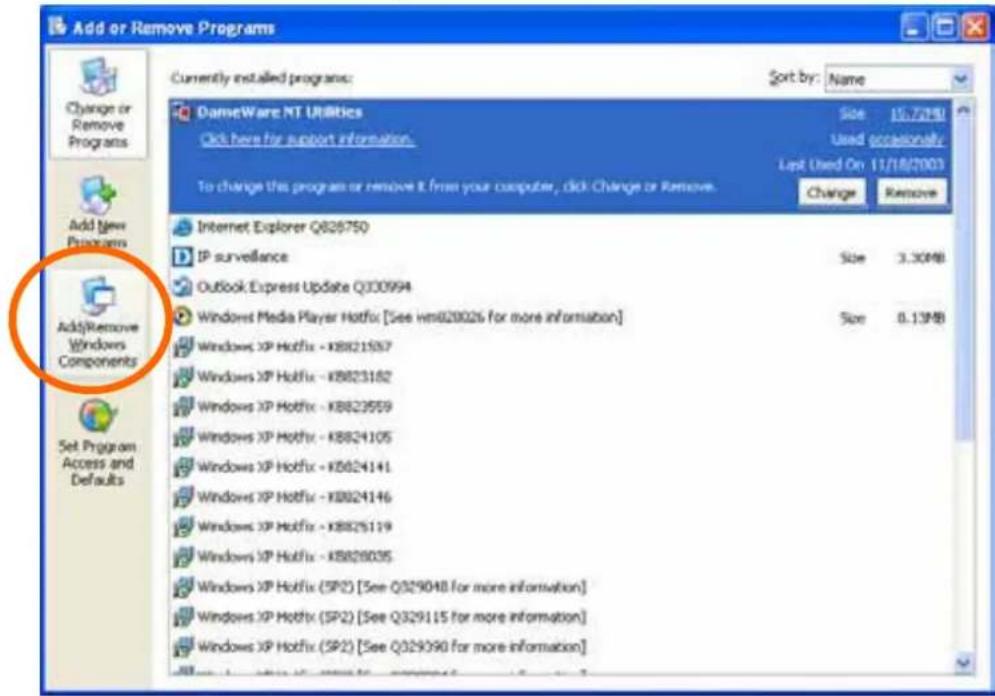
text_image
Add or Remove Programs Currently installed programs: Sort by: Name DameWare NT Utilities Click here for support information. Size 15.7MB Used occasionally Last Used On 11/18/2003 Change Remove Internet Explorer Q826750 IP surveillance Size 3.30MB Outlook Express Update Q330994 Windows Media Player Hotfix [See hm820026 for more information] Size 0.13MB Windows XP Hotfix - KB821597 Windows XP Hotfix - KB823182 Windows XP Hotfix - KB823559 Windows XP Hotfix - KB824105 Windows XP Hotfix - KB824141 Windows XP Hotfix - KB824146 Windows XP Hotfix - KB825119 Windows XP Hotfix - KB826035 Windows XP Hotfix (SP2) [See Q329048 for more information] Windows XP Hotfix (SP2) [See Q329115 for more information] Windows XP Hotfix (SP2) [See Q329390 for more information]The following screen will appear:
Select Networking Services
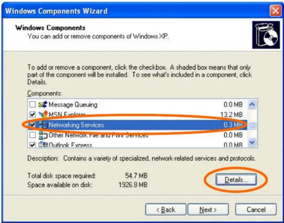
text_image
Windows Components Wizard Windows Components You can add or remove components of Windows XP. To add or remove a component, click the checkbox. A shaded box means that only part of the component will be installed. To see what's included in a component, click Details. Components: Message Queuing 0.0 MB MSN Explorer 13.2 MB Networking Services 0.3 MB Other Network File and Print Services 0.0 MB Outlook Express 0.0 MB Description: Contains a variety of specialized, network-related services and protocols. Total disk space required: 54.7 MB Space available on disk: 1926.8 MB Details... < Back Next > CancelSelect Universal Plug and Play
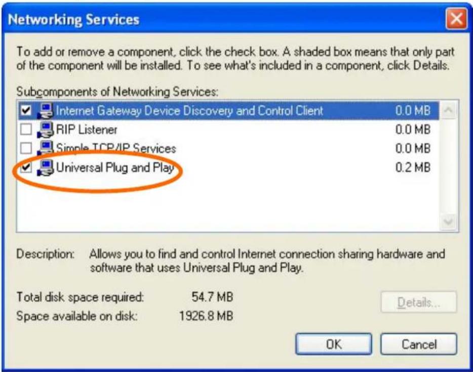
text_image
Networking Services To add or remove a component, click the check box. A shaded box means that only part of the component will be installed. To see what's included in a component, click Details. Subcomponents of Networking Services: Internet Gateway Device Discovery and Control Client 0.0 MB RIP Listener 0.0 MB Simple TCP/IP Services 0.0 MB Universal Plug and Play 0.2 MB Description: Allows you to find and control Internet connection sharing hardware and software that uses Universal Plug and Play. Total disk space required: 54.7 MB Space available on disk: 1926.8 MB Details... OK CancelClick Details
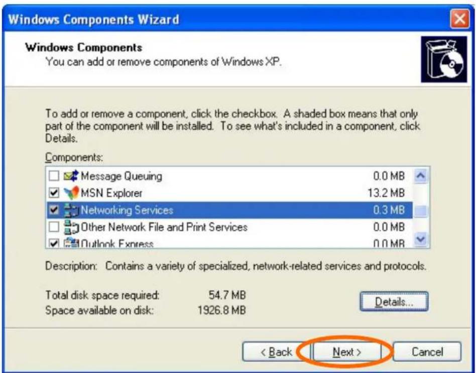
text_image
Windows Components Wizard Windows Components You can add or remove components of Windows XP. To add or remove a component, click the checkbox. A shaded box means that only part of the component will be installed. To see what's included in a component, click Details. Components: Message Queuing 0.0 MB MSN Explorer 13.2 MB Networking Services 0.3 MB Other Network File and Print Services 0.0 MB Outlook Express 0.0 MB Description: Contains a variety of specialized, network-related services and protocols. Total disk space required: 54.7 MB Space available on disk: 1926.8 MB Details... < Back Next > CancelClick Next
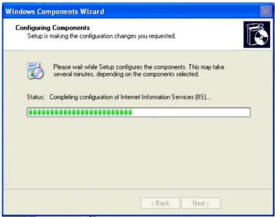
text_image
Windows Components Wizard Configuring Components Setup is making the configuration changes you requested. Please wait while Setup configures the components. This may take several minutes, depending on the components selected. Status: Completing configuration of Internet Information Services (IIS)... < Back Next >Please wait while Setup configures the components.
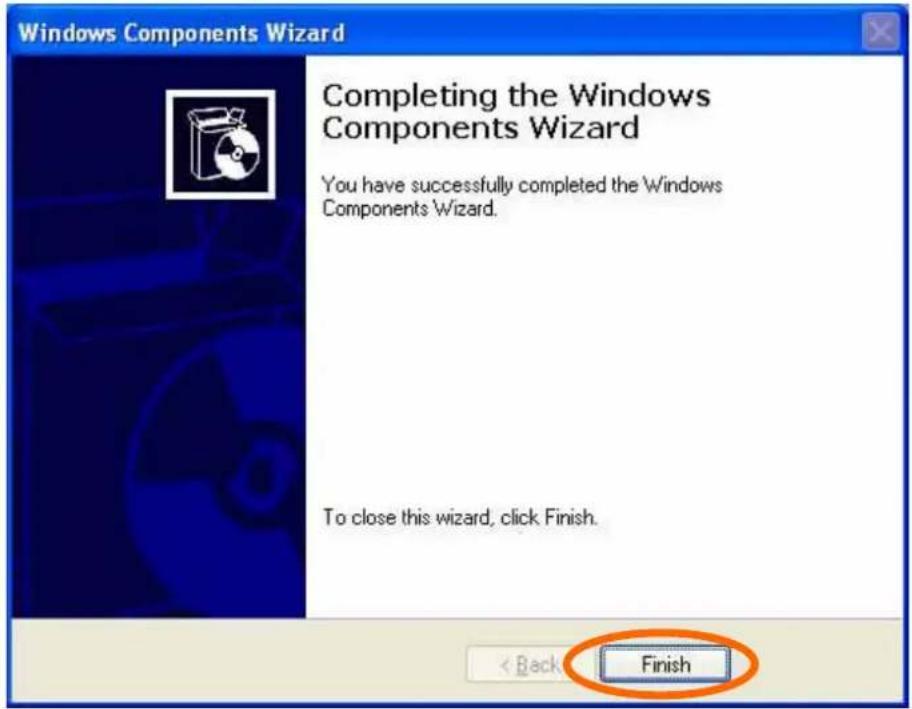
text_image
Windows Components Wizard Completing the Windows Components Wizard You have successfully completed the Windows Components Wizard. To close this wizard, click Finish. < Back FinishClick Finish