
Doblo (2009) - Automotive FIAT - Free user manual and instructions
Find the device manual for free Doblo (2009) FIAT in PDF.


| Product Type | Automotive |
| Brand | Fiat |
| Model | Doblo (2009) |
| Category | Automobile |
| Manual Language | English |
| Manual Pages | 218 |
| File Format | |
| Body Style | Minivan / MPV |
| Length | 4.240 m |
| Width | 1.995 m |
| Height | 1.845 m |
| Wheelbase | 2.755 m |
| Curb Weight | 1,200 - 1,400 kg |
| Fuel Type | Petrol / Diesel |
| Engine Displacement | 1.3L - 1.9L |
| Transmission | Manual 5-speed |
| Seating Capacity | 5 |
| Safety Features | ABS, Airbags, EBD |
| Maintenance Interval | Every 15,000 km |
| Recommended Oil | SAE 5W-40 (diesel) / 5W-30 (petrol) |
Frequently Asked Questions - Doblo (2009) FIAT
User questions about Doblo (2009) FIAT
0 question about this device. Answer the ones you know or ask your own.
Ask a new question about this device
Download the instructions for your Automotive in PDF format for free! Find your manual Doblo (2009) - FIAT and take your electronic device back in hand. On this page are published all the documents necessary for the use of your device. Doblo (2009) by FIAT.
USER MANUAL Doblo (2009) FIAT
O W N E R H A N D B O O K
Dear Customer,
Thank you for selecting Fiat and congratulations on your choice of a Fiat Doblò.
We have written this handbook to help you get to know all your new Fiat Doblò features and use it in the best possible way.
You should read it right through before taking the road for the first time.
You will find information, tips and important warnings regarding the driving of your vehicle to help you derive the maximum from your Fiat Doblò's technological features. You will find very valuable tips for your own safety, the vehicle's wellbeing and about how to protect the environment.
The enclosed Warranty Booklet lists the services that Fiat offers to its Customers:
- the Warranty Certificate with terms and conditions for maintaining its validity
- the range of additional services available to Fiat Customers.
Best regards and good motoring!
This Owner Handbook describes all Fiat Doblò versions. As a consequence, you should consider only the information which is related to the engine and bodywork version of the vehicle you purchased.
VERY IMPORTANT!
REFUELLING
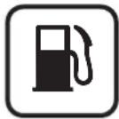
Petrol engines: only refuel with unleaded petrol with octane rating (RON) not less than 95.
Diesel engines: refuel diesel engine vehicles with diesel fuel for motor vehicles meeting EN590 European Specifications only.
The use of other products or mixtures may irreparably damage the engine with invalidation of the warranty due to the damage caused.
STARTING THE ENGINE
Make sure that the handbrake is up. Put the gearbox in neutral. Press the clutch pedal fully without pressing the accelerator. At this point:
petrol engines: turn the ignition key to AVV and release it as soon as the engine starts.
diesel engines: turn the ignition key to MAR and wait for the warning lights CODE (70) and 00 to go off; turn the ignition key to AVV and release it as soon as the engine has started.
PARKING ON FLAMMABLE MATERIAL

The catalytic converter develops high temperature during operation, Do not park the vehicle on grass, dry leaves, pine needles or other flammable material: fire hazard.
RESPECTING THE ENVIRONMENT
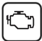
The vehicle is equipped with a system for continuously monitoring emissions control system components to ensure environmental-friendlier running.
ELECTRICAL ACCESSORIES

If you want to add electrically powered accessories after buying the vehicle (with the risk of gradually draining the battery) visit a Fiat Dealership. They will evaluate the overall electrical intake and check whether the electric system can support the required load.
CODE card

Keep the code card in a safe place, not in the vehicle. You should always keep the electronic card code written on the CODE card with you.
SCHEDULED SERVICING

Correct maintenance will preserve your vehicle's performance, safety features, environmental-friendliness and low running costs in time.
THE OWNER HANDBOOK CONTAINS ...

...information, tips and important warnings regarding the safe, correct driving of your vehicle, and its maintenance. Pay particular attention to the symbols ▲ (personal safety) ▶ (environmental protection) △ (the vehicle wellbeing).
WELCOME ABOARD Fiat Doblò
Fiat Doblò is a compact vehicle with an original bodyline, designed to offer great driving comfort, ensure safety and be a real friend to the environment.
Everything, from its new engines to its safety devices, from its improved comfort for driver and passengers alike to its practical solutions, contributes to make you appreciate your Fiat Doblò's personality.
And you will realise it later when you discover that its driving style and performance goes hand in hand with new manufacturing processes that help cut running costs.
The Fiat Doblò, for example, needs to be taken in for its first servicing after 20,000 km.
THE SIGNS TO HELP YOU DRIVE CORRECTLY
The signs you see on this page are very important. They highlight those parts of the handbook where, more than anywhere else, you should stop for a minute and read carefully.
As you can see, each sign has a different symbol to make it immediately clear and easy to identify the subjects in the different areas:

natural_image
Warning symbol with exclamation mark inside a triangle on pink background (no text)
natural_image
Simple white tree icon on gray background (no text or symbols)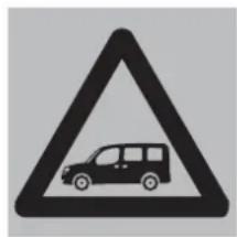
natural_image
Black triangular warning sign with a car silhouette inside (no text or symbols)Personal safety.
Important: total or partial failure to follow these instructions can place driver, passengers or others in serious danger.
Protecting the environment.
This shows you the correct procedures to follow to ensure that the vehicle does not harm the environment.
Vehicle well-being.
Important. Total or partial failure to follow these instructions will result in the risk of serious damage to the vehicle and may invalidate the warranty as well.
GETTING TO KNOW YOUR VEHICLE
SYMBOLS
Special coloured labels have been attached near or actually on some of the components of your Fiat Doblò. These labels bear symbols that remind you of the precautions to be taken as regards that particular component.
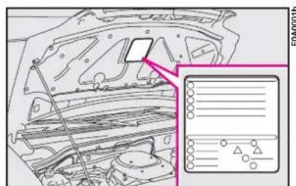
Plate A-fig. I summarising the symbols used can be found under the bonnet.
text_image
Technical diagram of an engine compartment with a highlighted component and a file inset showing internal components.fig. I
THE FIAT CODE SYSTEM
To further protect your vehicle from theft, it has been fitted with an engine immobilising system (Fiat CODE system) which is automatically activated when the ignition key is removed.
An electronic device, in fact, is fitted in each ignition key grip. The device transmits a radio-frequency signal when the engine is started through a special aerial built into the ignition switch. The modulate signal, which changes each time the engine is started, is the password by means of which the control unit recognises the key and enables to start the engine.
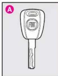
KEYS fig. 2
The following keys are provided with the vehicle:
- two keys A when the vehicle is not equipped with remote control;
- key A and key B when the vehicle is equipped with door lock remote control.
- Key A is the key that is used normally. It will:
- start the engine;
- lock/unlock front doors;
natural_image
Line drawing of a key with a handle and circular button (no text or symbols)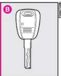
natural_image
Line drawing of a key with handle and control panel (no text or symbols)fig. 2
- lock/unlock the rear doors or the tailgate;
- lock/unlock the side doors, Cargo versions only;
- deactivate the passenger's airbag.
The key B, with a built-in remote control, has the same functions as key A in vehicles with door lock remote control.
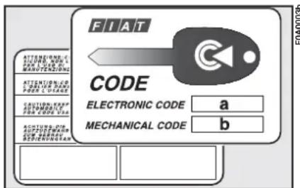
The CODE card fig. 3 is also supplied with the keys and bears the following:
a - the electronic code to be used for emergency starting (see “Emergency start-up” in section “In an emergency”);
text_image
FIAT CODE ELECTRONIC CODE a MECHANICAL CODE bfig. 3
b - the mechanical key code to be given to the Fiat Dealership when ordering duplicate keys.
Keep the CODE card in a safe place.
Make sure you have the electronic code of the CODE card with you at all times in the event you have to perform an emergency start-up.
OPERATION
Each time the ignition key is turned to STOP, or PARK, the protection system will automatically immobilise the engine.
When the key is turned to MAR to start the engine:
1) if the code is recognised the (CODE) warning light on the instrument panel will flash briefly; this means the protection system has recognised the key code and deactivates the immobiliser, turn the key to AVV, and the engine will start.
2) If the warning light code (7) stays on, the code was not recognised. In this case, turn the key to STOP and then back to MAR. If the engine re-
mains immobilised, try with the other key provided.
If you are still unable to start the engine, use the emergency starting procedure (see "In an emergency") and take your vehicle to the nearest Fiat Dealership.
When the vehicle is travelling and the key is at MAR:
1) if the warning light CODE (E) comes on while the vehicle is moving, this means that the system is running a self-test (e.g. due to a voltage drop).
2) if the warning light CODE (flashes), the vehicle is not protected by the engine immobiliser. Contact a Fiat Dealership immediately and get them to store the codes of all the keys in the memory.
IMPORTANT The electronic components inside the key may be damaged if the key is subjected to sharp knocks.
IMPORTANT Each key provided with the vehicle has its own code, different from all the others, which must be stored in the memory of the system control unit.
DUPLICATE KEYS
When additional keys are required, go to your Fiat Dealership taking all the keys in your possession and the CODE card with you. The Fiat Dealership will store the old and new keys (up to eight) in the system. The Fiat Dealership may ask you to demonstrate that you own the vehicle.
The codes of any keys that are not handed over when the new storage procedure is carried out will be deleted from the memory to prevent any lost or stolen keys being used to start the vehicle.
All the keys and the CODE card must be handed over to the new owner when selling the vehicle.
DOOR LOCK REMOTE CONTROL
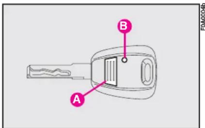
The remote control is built into the ignition key. Press button A-fig. 4 to lock and unlock the doors.
Press button A to operate the system. LED B (where required) will flash while the transmitter is sending the code to the receiver.
The ceiling light and map-reading light will come on for the predefined time when the doors are unlocked with the remote control.
text_image
A B F0A0004bfig. 4
For ordering additional remote controls or replacing the batteries, see the following paragraphs.
IMPORTANT The remote control system frequency can be disturbed by significant radio transmissions outside the vehicle (e.g: mobile phones, HAM radio systems, etc.) that could cause remote control malfunctioning.
Ministerial homologation
In accordance with the legislation covering radio frequencies in force in each country, we should like to point out that:
– the market-specific homologation numbers are listed in the paragraph "Radio-frequency remote controls" in section "Technical specifications".
– for markets requiring transmitter marking, the transmitter code is printed on the remote control.
ORDERING ADDITIONAL REMOTE CONTROLS
The system can recognise up to 8 keys with incorporated remote control.
If additional remote controls are required for any reasons, go to a Fiat Dealership, taking all the keys you own and the CODE card with you.
REPLACING THE BATTERIES
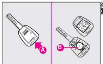
Change the batteries (using spare batteries of the same kind) as follows. Open the plastic case by inserting a screwdriver in recess A-fig. 5. Insert new batteries B respecting the polarity and close the plastic case.
Used batteries are harmful to the environment. They should be disposed of as specified by law in the special containers provided, or take them to a Fiat Dealership, which will deal with their disposal.
SEAT BELTS
USING THE SEAT BELTS
The belt should be worn keeping the chest straight and rested against the seat back.
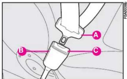
Take hold of the tongue A-fig. 6. Insert it into the buckle B, until you hear it clicks.
At removal, if it jams, let it rewind for a short stretch, then pull it out again without jerking.
text_image
A B F0A0005bfig. 5
text_image
A B C F0A0006bfig. 6

Never press button C when travelling.
To unfasten the seat belts, press button C. Guide the seat belt with your hand while it is rewinding, to prevent it from twisting.
Through the reel, the belt automatically adapts to the body of the passenger wearing it, allowing freedom of movement.
When the vehicle is parked on a steep slope the reel mechanism may block; this is normal. The reel mechanism prevents the webbing coming out when it is jerked or if the vehicle brakes sharply, as in a collision or when cornering at high speed.
natural_image
Line drawing of a vehicle interior showing seatbelt and dashboard (no text or symbols)fig. 7
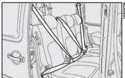
Every rear seat (where provided) is fitted with inertial seat belts with three anchor points and reel.
IMPORTANT Before fastening the seat belts make sure the seat is properly anchored.
7-seat versions
In the 7-seat versions, every rear seat (second and third row) is fitted with seat belts with three anchor points and reel fig. 7.

Remember that in the case of a violent collision, back seat passengers not g seat belts also represent us danger to the passen-the front seats.
ADJUSTING THE FRONT SEAT BELT HEIGHT

Make the height adjustment when the vehicle is stationary.
Always adjust the height of the seat belt to fit the person wearing it. This could greatly reduce the risk of injury in the case of collision.
The belt is adjusted properly when the webbing passes approximately halfway between the edge of the shoulder and the neck. Four height adjustments are possible.
text_image
B Afig. 8
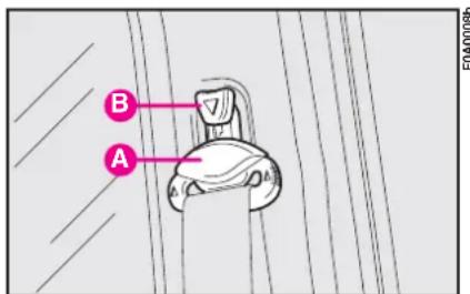
To raise the belt: raise loop A-fig. 8 to the required position.
To lower the belt: press knob B, and at the same time move loop A to the required position.
Check that the seat belt is locked in position by pushing down on loop A without pressing knob B.

After you have made the adjustment, always make sure that the loop is attached firmly in one of the fixed positions and cannot move. To do this, with the button released, exert a further pressure to allow the anchoring device to catch if release did not take place at one of the preset positions.
PRETENSIONERS
The Fiat Doblò (with passenger's air bag) is fitted with pretensioners on the front side seats to improve the protection provided by the seat belts. These devices "feel", that a violent collision is in progress via a sensor and pull back a few inches of webbing. In this way the pretensioner ensures that the belt is adhering perfectly to the body before the belt begins to hold back the wearer.
The seat belt locks to indicate that the device has intervened; the seat belt cannot be drawn back up even when guiding it manually.
IMPORTANT The pretensioner will give maximum protection when the seat belt adheres snugly to the wearer's chest and hips.
Some smoke may be produced when the pretensioners are fired. This smoke is harmless and does not indicate the principle of a fire.
The pretensioner does not require any maintenance or greasing. Anything that modifies its original conditions invalidates its efficiency. If due to unusual natural events (floods, seas storm, etc.) the device has been affected by water and mud, it must necessarily be replaced.
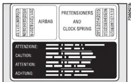
The pretensioner can only be used once. Following a collision that has triggered it, have it replaced at a Fiat Dealership. Pretensioner validity is written on the plate, fig. 9, set inside the glove box. Have pretensioners replaced at a Fiat Dealership as this date approaches.
Load limiting device
This device reduces the load with is normally exerted by the seat belts on the passenger's shoulder and chest in a collision. It increases protection by preventing the micro traumas which are inevitable in road accidents (also in vehicles with airbags). The device is built into the belt reel.
text_image
2012019207 2012019208 AIRBAG PRETENSIONERS AND CLOCK SPRING 2013 2014/2015 01/02/03/04/05/06 02/08/09/10/11/12 ATTENZIONE: CAUTION: ATTENTION: ACHTUNG:fig. 9
Operations involving banging, vibrations or heating (exceeding 100°C for a maximum of 6 hours) in the area around the pretensioner may trigger or damage the device. Vibrations from rough road surfaces or accidental jolting caused by mounting pavements etc. do not have any effect on the pretensioner. If, however, you need any assistance, go to a Fiat Dealership.
GENERAL INSTRUCTIONS FOR USING THE SEAT BELTS
The driver is responsible for respecting and enforcing the local rules and laws regarding the use of seat belts.
Always fasten the seat belts before starting.
For maximum safety, keep the back of your seat upright, lean back into it and make sure the seat belt fits closely across your chest and hips. Always fasten seat belts, in front and rear seats! Travelling without seat belts increases the risk of severe and fatal injury in the event of a crash.
Under no circumstances should the components of seat belts and pretensioners be tampered with or removed. Any interventions should be carried out by qualified and authorised personnel. Always contact a Fiat Dealership.
natural_image
Line drawing of two people seated in a chair, viewed from the side (no text or symbols)fig. 10
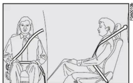
The webbing must not be twisted. The upper section must pass across the shoulder and chest diagonally. The lower part must fit closely across the passenger's hips, fig. 10, and not the abdomen, to prevent them from sliding forwards. Do not use clips, fasteners etc. to prevent the belt adhering to the passenger's body.
If the belt has been subjected to heavy stress, for example after an accident, it should be changed completely together with the anchors, anchor fastening screws and the pretensioners. In fact, even if the belt has no visible defects, it could have lost its resilience.

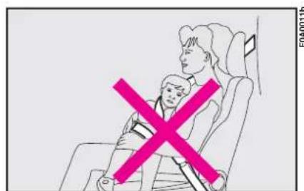
Never travel with a child sitting on the passenger's lap with a single belt to them both, fig. 11. Do not other objects to the body.
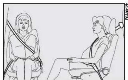
Seat belts must also be worn by expectant mothers: the risk of injury in the case of accident is much greater for them and their unborn child too if they do not have a seat belt on. Of course they must position the lower part of the belt very low down so that it passes under the abdomen fig. 12.
HOW TO KEEP THE SEAT BELTS IN PROPER WORKING ORDER AT ALL TIMES
1) When wearing the seat belts, always ensure they are not twisted and are free to wind in and out.
2) Following a serious accident, replace the belt being worn at that time, even if it does not seem damaged. Always replace the seat belts if pretensioners have been activated.
3) When cleaning the belts, wash them by hand with water and neutral soap, rinse them and let them dry in the shade. Do not use strong detergents, bleach, colouring or any other chemical substance that could weaken the belt fibres.
4) Do not allow the reel mechanisms to get wet: they are only guaranteed to work properly if they remain dry.
5) Replace the seat belt when showing significant wear or cut signs.
text_image
FOA00116fig. 11
natural_image
Line drawing of two people seated in a shared seat, one using a cable device (no text or symbols)fig. 12
TRANSPORTING CHILDREN SAFELY


SERIOUS DANGER: Never place cradle child's seats not facing the running direction on the front seat of vehicles with passenger's airbag, which during inflation could cause serious injury, even mortal. You are advised to carry children always on the rear seat, as this is the most protected position in the case of a crash. In any case, child' seats must absolutely not be fitted on the front seats of vehicles with passenger's airbag, which during inflation could cause serious injury, even mortal, regardless of the seriousness of the crash that triggered it. Children may be placed on the front seat of vehicles fitted with passenger's airbag deactivation. In this case, it is absolutely necessary to check the warning light ☐ on the instrument panel to make sure that deactivation has actually taken place (see paragraph FRONT AND SIDE AIRBAGS AT ITEM FRONT PASSENGER AIRBAG). The front passenger's seat shall be adjusted in the most backward position to prevent any contact between child's seat and dashboard.
For optimal protection in the event of a crash, all passengers must be seated and wearing adequate restraint systems.
This is even more important for children.
This prescription is compulsory in all EC countries according to EC Directive 2003/20/EC.
Compared with adults, their head is proportionally larger and heavier than the rest of the body, while the muscles and bone structure are not completely developed. Therefore, correct restraint systems are necessary, other than adult seat belts.
The results of research on the best child restraint systems are contained in the European Standard ECE-R44. This Standard enforces the use of restraint systems classified in five groups:
Group 0 0-10 kg in weight
Group 0+ 0-13 kg in weight
Group I weight 9-18 kg
Group 2 15-25 kg in weight
Group 3 22-36 kg in weight
The groups partially overlap. This is because there are systems which cover more than one weight group.
All restraint devices must bear the certification data, together with the control brand, on a solidly fixed label which must absolutely never be removed.
Over 1.50 m in height, from the point of view of restraint systems, children are considered as adults and wear the seat belts normally.
Lineaccessori Fiat offers seats for each weight group, which are the recommended choice, as they have been designed and experimented specifically for Fiat vehicles.
GROUP 0 and 0+
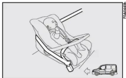
Babies up to 13 kg must be carried facing backwards on a cradle seat, which, supporting the head, does not induce stress on the neck in the event of sharp deceleration.
The cradle is restrained by the vehicle seat belts, as shown in fig. 14 and in turn it must restrain the child with its own belts.

The figure is only an example for mounting. At-tain to the instructions
for fastening which must be enclosed with the specific child restraining system you are using.
GROUP I
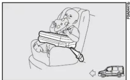
Children from 9 to 18 kg are to be seated facing forward in child seats with front cushion fig. 15. The vehicle seat belt secures both seat and child.
natural_image
Illustration of a baby in a car seat with a car nearby (no text or symbols)fig. 14
natural_image
Illustration of a baby car inside a car seat, with a car approaching it (no text or symbols)fig. 15

The figure is only an example. Attain to the instructions for fastening which must be enclosed with the specific child restraint system you are using.
GROUP 2
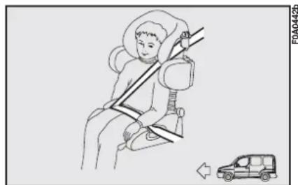
Children from 15 to 25 kg can be secured directly with the vehicle seat belts. The seat has the purpose of positioning the child correctly with respect to the seat belt so that the diagonal section crosses the child's chest (never the child's throat) and the horizontal section fits snugly on the child's hips (and not the child's abdomen) fig. 16.
GROUP 3
For children from 22 kg up to 36 kg the size of the child's chest no longer requires a support to space the child's back from the seat back.
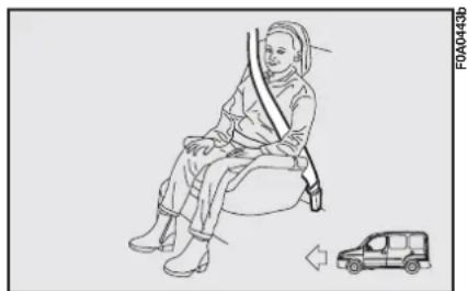
Fig. 17 shows proper child seat positioning on the rear seat.
Children taller than 1.50 m can wear seat belts like adults.

Seats exist which are suitable for covering weight groups 0 and 1 with a rear connection to the vehicle belts and their own belts to restrain the child. Due to their size, they can be dangerous if installed incorrectly fastened to the vehicle belts with a cushion. Carefully follow the instructions for installation provided with the seat.

The figure is only an example. Attain to the instructions for fastening which must be enclosed with the specific child restraint system you are using.
text_image
FDA04426fig. 16
natural_image
Line drawing of a person sitting on a chair with a car nearby (no text or symbols)fig. 17
Passenger seat compliance with regulations on child's seat use
Fiat Doblò complies with the new EC Directive 2000/3/CE regulating child's seat assembling on the different vehicle seats according to the table below:
| Group | Range of weight | FRONT SEATFront passenger | REAR SEAtsecond rowSide and central passengers | REAR SEATthird rowSide passengers |
| Group 0, 0+ up | to 13 kg U UX | |||
| Group 1 9 - | 8 kg U UX | |||
| Group 2 15 - | 25 kg U UX | |||
| Group 3 22 - | 36 kg U UX |
Key:
U = suitable for child restraint systems of the “Universal” category, according to European Standard ECE-R44 for the specified “Groups”.
X = Unsuitable for children in this group.
To sum up the safety precautions to follow when transporting children.
I) The recommended position for installing child's seat is on the rear seat, as it is the most protected in the case of a crash.

In vehicles fitted with passenger airbag, never place child's restraint sys-n the front seat.
2) If the passenger's airbag is deactivated always check the warning light on the instrument panel to make sure that it has actually been deactivated.
3) Attain to the instructions for fastening the specific child restraint system which you are using. These instructions must be provided by the manufacturer. Keep the child restraint system installation instructions with the vehicle documents and with this Handbook. Never use a child restraint system without installation instructions.
4) Always check the seat belt is well fastened by pulling the webbing.
5) Only one child is to be strapped to each retaining system.
6) Always check the seat belts do not fit around the child's throat.
7) While travelling, do not let the child sit incorrectly or release the belts.
8) Passengers should never carry children on their laps. No-one, however strong they are, can hold a child in the event of a crash.
9) Replace the child restraint system after an accident.
IGNITION DEVICE
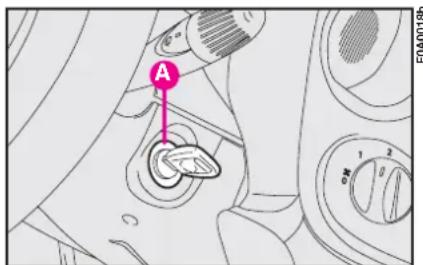
The key can be turned to 4 different positions fig. 26:
- STOP: engine off, key can be removed, steering column locked. Some electrical devices can be worked (e.g. sound system, electric window winders).
- MAR: drive position. All electrical devices can be used.
- AVV: engine ignition.
- PARK: engine off, parking lights on, steering column locked. Press button A and turn the key to PARK.
text_image
A 1 2 0 F0A0018bfig. 26
If the ignition device is tampered with (e.g.: attempted theft), have it checked over by a Fiat Dealership as soon as possible.
When you get out of the vehicle, always remove the ignition key. This will prevent anyone from accidentally working the controls. Remember to apply the handbrake and, if the vehicle is faced down on a steep slope engage the first gear. If it is facing up, engage the reverse gear. Never leave unsupervised children in the vehicle.
STEERING COLUMN LOCK
To engage the lock: remove the ignition key at STOP or PARK and turn the steering wheel until it locks.
To release the lock: rock the steering wheel slightly as you turn the ignition key to MAR.
Never remove the ignition key while the vehicle is moving. The steering wheel would automatically lock as soon as you try to turn it. This also applies when the vehicle is being towed.
It is absolutely forbidden to carry out whatever after-market operation involving steering system or steering column modifications (e.g.: installation of anti-theft device) that could badly affect performance and safety, cause the lapse of warranty and also result in non-compliance of the vehicle with homologation requirements.
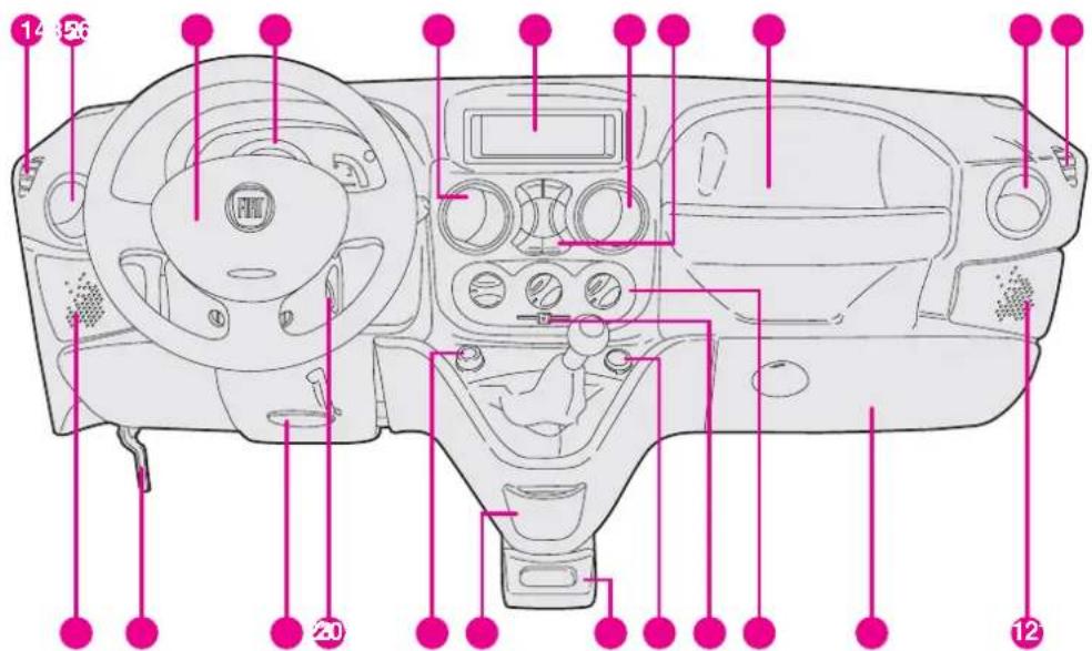
DASHBOARD
The presence and the position of the instruments and warning lights may vary according to the versions.
text_image
14 26 20 12FDA0701b
1. Fixed side vent - 2. Adjustable side vent - 3. Horn - 4. Instrument panel - 5. Adjustable central vent - 6. Glove compartment - 7. Adjustable central vent - 8. Central controls - 9. Glove compartment - 10. Adjustable side vent - 11. Fixed side vent - 12. Front right-hand speaker housing - 13. Glove compartment - 14. Heater/ventilation/climate control system controls - 15. Recirculation slider - 16. Additional power socket - 17. Glove compartment - 18. Ashtray - 19. Cigar lighter - 20. Ignition switch - 21. Steering wheel adjustment lever - 22. Bonnet opening lever - 23. Front left-hand speaker housing
fig. 27
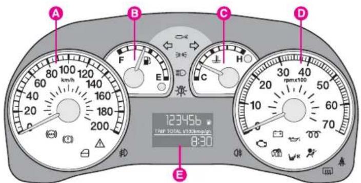
INSTRUMENT PANEL
text_image
A B C D 123456 TAM TOTAL 1000mpa 8:30 Efig. 28
F0A0444b
text_image
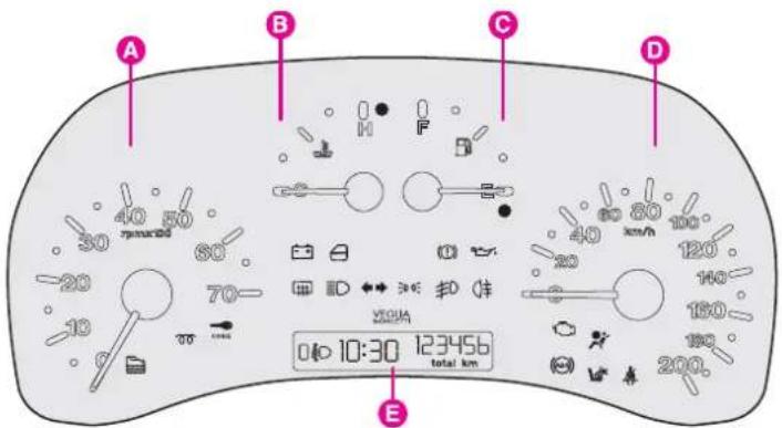
A B C D 40 50 rpm/100 30 80 20 70 10 E 10:30 123456 total km 200.fig. 29
F0A0445b
1.4 8v - 1.3 Multijet -
1.9 Multijet versions
A - Speedometer (speed indicator)
B - Fuel level gauge with reserve warning light
C - Engine coolant temperature gauge and max. temperature warning light
D - Rev counter
E - Multifunction display
Warning lights 00 and are only provided on Diesel versions.
Natural Power versions
A - Rev counter.
B - Engine coolant temperature gauge and excessive temperature warning light.
C - Fuel level gauge with reserve warning light.
D - Speedometer.
E - Digital display.
Warning lights 00 and are only provided on Diesel versions.
text_image
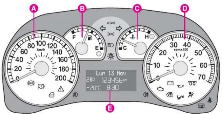
A B C D 80 km/h 120 140 160 180 200 20 40 60 80 100 120 140 160 180 200 E F G H I J K Lun 13 Nov 24 123456km -20°C 8:30 Efig. 30 - With outside temperature sensor and/or Diesel Particulate Filter for Multijet versions.
F0A0500b
1.4 8v - 1.3 Multijet -
1.9 Multijet versions
A - Speedometer
B - Fuel level gauge with reserve warning light.
C - Engine coolant temperature gauge and excessive temperature warning light.
D - Rev counter.
E - Digital display.
Warning lights 00 and are only provided on Diesel versions.
INSTRUMENTS
SPEEDOMETER
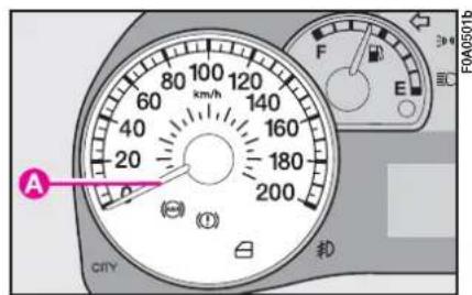
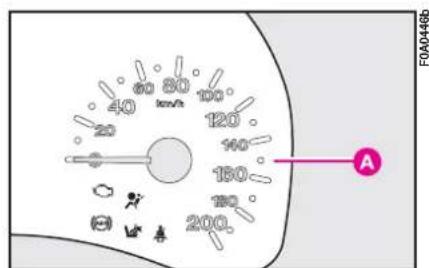
The speedometer A-fig. 31 - 32 shows the vehicle speed.
text_image
A (F) 30-40 E FOA0501b CITY 200 180 160 140 120 100 80 km/hfig. 31
REV COUNTER
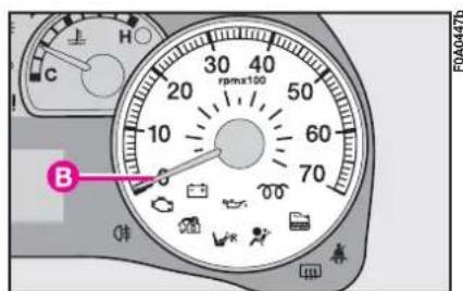
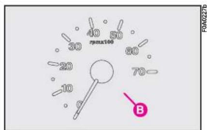
Rev. counter B-fig. 33 - 34 shows engine rpm.
IMPORTANT The electronic system progressively blocks fuel flow to prevent engine from overrevving. This will lead to a progressive loss of engine power. When the engine is idling, the rev counter may indicate a gradual or sudden highering of the speed. This is normal as it takes place during normal operation, for example when activating the climate control system or the fan. In particular a slow change in the speed preserves the battery charge.
text_image
40 60 80 100 25 120 140 160 180 200 A FOA0446bfig. 32
text_image
C h 30 40 20 50 10 60 70 rpmx100 B F0A0447bfig. 33
text_image
40 50 rpoa100 30 60 20 70 10 B F0A0227bfig. 34
FUEL LEVEL GAUGE
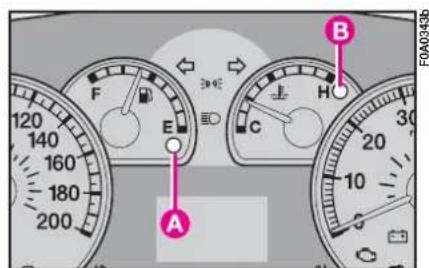
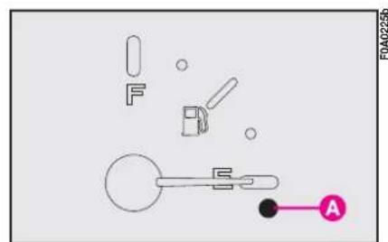
The needle shows the fuel present in the tank. When the fuel reserve warning light A-fig. 35 - 36 comes on (on certain versions with the dedicated message on the reconfigurable multifunction display) it means that there are approximately 5-7 litres of fuel left in the tank.
E - tank empty.
F - tank full.
Never travel with the tank almost empty: lack of fuel could damage the catalyser.
IMPORTANT The needle will point to E and the reserve warning light A will flash to indicate a fault in the system. Contact a Fiat Dealership to have the system checked.
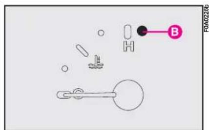
ENGINE COOLANT TEMPERATURE GAUGE
This gauge shows the temperature of the engine coolant fluid and begins working when the fluid temperature exceeds approx. 50 °C.
Under normal conditions, the needle should move to different positions of the scale according to the working conditions and engine cooling conditions.
C - Low engine coolant temperature
H - High engine coolant temperature
Warning light B-fig. 35 - 37 comes on (on certain versions with the dedicated message on the reconfigurable multifunction display) to indicate that engine coolant temperature is too high; in this event stop the engine and contact Fiat Dealership.

If the needle reaches the red area, stop the engine immediately and contact
a Fiat Dealership.
text_image
A B F E H C 20 10 30 FOA0343bfig. 35
text_image
F B Afig. 36
text_image
FOA0226bfig. 37
DIGITAL DISPLAY
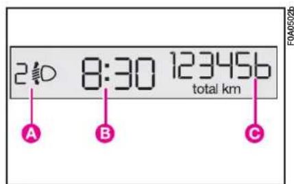
"STANDARD" SCREEN fig. 38
The standard screen shows the following indications:
A - Headlight aiming position display (with dipped beam headlights on).
B - Clock (always displayed, also with key removed and front doors closed).
C - Odometer (km or miles covered).
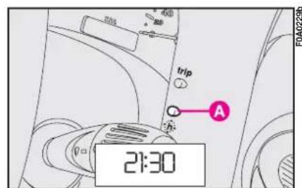
CONTROL BUTTONS fig. 39
A - Clock.
CLOCK fig. 39
To adjust the clock press button A. The clock will advance by one unit each time the button is pressed. Press the button and hold it down for a few seconds to rapidly advance the time automatically. When the clock draws near to the correct time, release the button and complete the regulation manually.
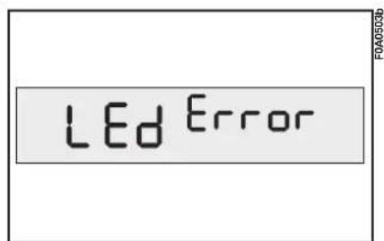
WARNING LIGHT TEST
fig. 40
The following warning lights are tested:
- handbrake on/low brake fluid level;
- ABS and EBD system (where provided);
This tests are carried out automatically when turning the ignition key to MAR and during normal operation when a fault is found. At the end of the initial check, the display will show failures, if any (through one or more warning lights) by the wording "LED Error" flashing for about 10 seconds.
text_image
2:30 8:30 123456 total km A B C FOA0502bfig. 38
text_image
trip A 21:30fig. 39
text_image
LED Errorfig. 40
MULTIFUNCTION DISPLAY
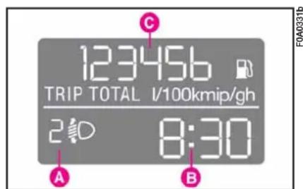
STANDARD SCREEN fig. 41
The standard screen shows the following indications:
A - Headlight aiming position display (with dipped beam headlights on).
B - Clock.
C - Odometer (km or miles covered).
Note With ignition key removed, when opening one of the front doors the display comes on showing the clock and km/mi covered for a few seconds.
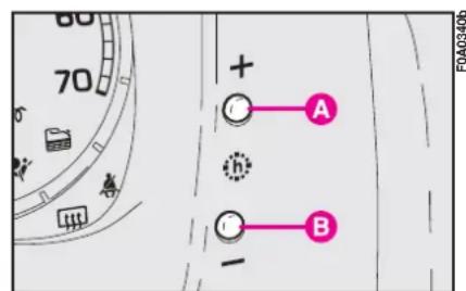
CLOCK fig. 42
To adjust the clock press button A to increase minutes and button B to decrease minutes. The clock will advance by one unit each time the button is pressed. Press the button and hold it down for a few seconds to rapidly advance the time automatically. When the clock draws near to the correct time, release the button and complete the regulation manually.
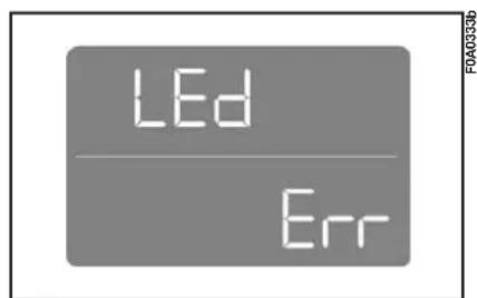
WARNING LIGHT TEST
fig. 43
The following warning lights are tested:
- handbrake on/low brake fluid level;
- ABS and EBD system (where provided);
This tests are carried out automatically when turning the ignition key to MAR and during normal operation when a fault is found. At the end of the initial check, the display will show failures, if any (through one or more warning lights) by the wording LEd Err flashing for about 10 seconds.
text_image
123456 TRIP TOTAL I/100kmip/gh 2:10 8:30 A B C FOA0331bfig. 41
text_image
70 + A B -fig. 42
text_image
LED Errfig. 43
RECONFIGURABLE MULTIFUNCTION DISPLAY (where provided)
The vehicle can be provided with the reconfigurable multifunction display that shows useful information, according to the previous settings made, necessary when driving.
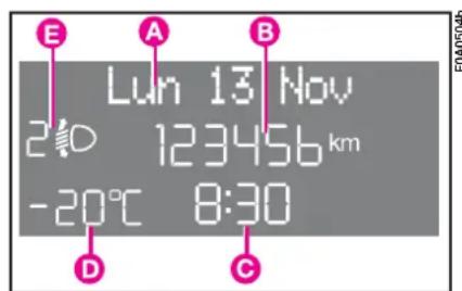
"STANDARD" SCREEN fig. 44
The standard screen shows the following indications:
A - Date
B - Odometer (km or miles covered)
C - Clock
D - External temperature (where provided)
text_image
E A B Lun 13 Nov 2:10 123456 km -20°C 8:30 D Cfig. 44
E - Headlight aiming position (only with dipped beam headlights on).
Note With key removed, when opening one of the front doors, the display will turn on and show for a few seconds the clock and the km or mi covered.
CONTROL BUTTONS fig. 45
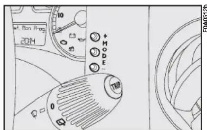
+ To scroll the displayed menu and the related options upwards or to increase the value displayed.
text_image
set. Non Prog 2014 10 + MODE - TWO FOA0512bfig. 45
MODE Brief press to open the menu and/or to move to next screen or to confirm the option required.
Long press to go back to the standard screen.
- To scroll the displayed menu and the related options downwards or to decrease the value displayed.
Note Buttons + and - activate different functions according to the following situations:
To adjust light inside the passenger compartment
- when standard screen is active, to adjust brightness inside the passenger compartment.
Setup menu
- to scroll the menu options upwards and downwards;
– to increase or decrease values during settings.
SETUP MENU
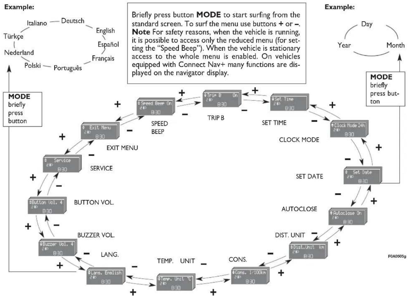
The menu comprises a series of functions arranged in a “circular fashion” which can be selected through buttons + and – to access the different select operations and settings (setup) given in the following paragraphs.
The setup menu can be activated by pressing briefly button MODE.
Single presses on buttons + or - will scroll the setup menu options.
Handling modes differ with each other according to the characteristic of the option selected.
Selecting a menu option
- press briefly button MODE to select the menu option to set;
- press buttons + or - (by single presses) to select the new setting;
- press briefly button MODE to store the new setting and to go back to the previously selected menu option.
Selecting "Set Date" and "Set time":
- briefly press button MODE to select the first value to change (e.g. hours /minutes or year / month / day);
- press buttons + or - (by single presses) to select the new setting;
- briefly press button MODE to store the new setting and to go to the next setup menu option, if this is the last one you will go back to the previously selected option of the main menu.
Press button MODE for long:
- to quit the setup menu and to save only the settings stored yet by the user (and confirmed by pressing briefly button MODE).
The setup menu displaying is timed; when quitting the menu due to timing expiry, only settings stored yet by the user (and confirmed by pressing briefly button MODE) will be saved.
flowchart
graph TD
    A["MODE briefly press button"] --> B["Exit Menu B30"]
    B --> C["Service B30"]
    C --> D["Button vol. 4 B30"]
    D --> E["Buzzer Vol. 4 B30"]
    E --> F["Lane. English B30"]
    F --> G["Temp. Unit °C B30"]
    G --> H["Cons. 1/100km B30"]
    H --> I["Dist. Unit km B30"]
    I --> J["AUTOCLOSE"]
    J --> K["Set Date B30"]
    K --> L["CLOCK MODE"]
    L --> M["SET TIME"]
    M --> N["Trip B On B30"]
    N --> O["Speed BeeP"]
    O --> P["EXIT MENU"]
    P --> Q["EXIT MENU"]
    Q --> R["STOP Box On B30"]
    R --> S["TRIP B"]
    S --> T["SET Time"]
    T --> U["Clock Mode 24h B30"]
    U --> V["CLOCK MODE"]
    V --> W["SET DATE"]
    W --> X["AUTOCLOSE"]
    X --> Y["DIST. UNIT km B30"]
    Y --> Z["TEMP. UNIT °C B30"]
    Z --> AA["LANG."]
    AA --> AB["Buzzer VOL."]
    AB --> AC["EXIT MENU"]
    AC --> AD["EXIT MENU"]
    AD --> AE["STOP Box On B30"]
    AE --> AF["Trip B On B30"]
    AF --> AG["SET TIME"]
    AG --> AH["Trip B On B30"]
    AH --> AI["STOP Box On B30"]
    AI --> AJ["Trip B On B30"]
    AJ --> AK["SET TIME"]
    AK --> AL["Trip B On B30"]
    AL --> AM["SET TIME"]
    AM --> AN["Trip B On B30"]
    AN --> AO["Trip B On B30"]
    AO --> AP["Trip B On B30"]
    AP --> AQ["Trip B On B30"]
    AQ --> AR["Trip B On B30"]
    AR --> AS["Trip B On B30"]
    AS --> AT["Trip B On B30"]
    AT --> AU["Trip B On B30"]
    AU --> AV["Trip B On B30"]
    AV --> AW["Trip B On B30"]
    AW --> AX["Trip B On B30"]
    AX --> AY["Trip B On B30"]
    AY --> AZ["Trip B On B30"]
    AZ --> BA["Trip B On B30"]
    BA --> BB["Trip B On B30"]
    BB --> BC["Trip B On B30"]
    BC --> BD["Trip B On B30"]
    BD --> BE["Trip B On B30"]
    BE --> BF["Trip B On B30"]
    BF --> BG["Trip B On B30"]
    BG --> BH["Trip B On B30"]
    BH --> BI["Trip B On B30"]
    BI --> BJ["Trip B On B30"]
    BJ --> BK["Trip B On B30"]
    BK --> BL["Trip B On B30"]
    BL --> BM["Trip B On B30"]
    BM --> BN["Trip B On B30"]
    BN --> BO["Trip B On B30"]
    BO --> BP["Trip B On B30"]
    BP --> BQ["Trip B On B30"]
    BQ --> BR["Trip B On B30"]
    BR --> BS["Trip B On B30"]
    BS --> BT["Trip B On B30"]
    BT --> BU["Trip B On B30"]
    BU --> BV["Trip B On B30"]
    BV --> BW["Trip B On B30"]
    BW --> BX["Trip B On B30"]
    BX --> BY["Trip B On B30"]
    BY --> BZ["Trip B On B30"]
    style A fill:#f9f,stroke:#333
    style AD fill:#ccf,stroke:#333
Speed limit (Speed Beep)
With this function it is possible to set the vehicle speed limit (km/h or mph), when this limit is exceeded the driver is immediately alerted (see section "Warning lights and messages").
To set the speed limit, proceed as follows:
- briefly press button MODE: (Off) will flash on the display;
- press button +: (On) will flash on the display;
- briefly press button MODE and then + or - to set the required speed (during setting the value flashes).
Note The possible setting is between 30 and 250 km/h, or between 20 and 155 mph depending on the unit set previously (see “Distance unit (Dist. Unit)” paragraph described later. Every press on button + / - increases/decreases by 5 units. Keeping the button + / - pressed obtains the automatic fast increase or decrease. When you are near the required setting complete adjustment by single presses.
- briefly press button MODE to go back to the menu screen or press the button for long to go back to the standard screen without storing settings.
To cancel the setting, proceed as follows:
- briefly press button MODE: (On) will flash on the display;
- press button -: (Off) will flash on the display;
- briefly press button MODE to go back to the menu screen or press the button for long to go back to the standard screen without storing settings.
Trip B On/Off (Trip B)
Through this option it is possible to activate (On) or deactivate (Off) the Trip B (partial trip).
For further details see paragraph "Trip computer".
For activation / deactivation, proceed as follows:
- briefly press button MODE: (On) or (Off) will flash on the display (according to previous setting);
- press button + or - for setting;
- briefly press button MODE to go back to the menu screen or press the button for long to go back to the standard screen without storing settings.
Set clock (Set clock)
This function enables to set the clock.
To set the clock (hours - minutes) proceed as follows:
- briefly press button MODE: "hours" will flash on the display;
- press button + or - for setting;
- briefly press button MODE: "minutes" will flash on the display;
- press button + or - for setting.
Note Every press on the button + or – increases/decreases by one unit. Keeping the button pressed obtains automatic fast increase/decrease. When you are near the required setting complete adjustment by single presses.
- briefly press button MODE to go back to the menu screen or press the button for long to go back to the standard screen without storing settings.
Clock mode (Click. Mode)
This function is used to set the clock in the 12h (12 hours) or 24h (24 hours) mode.
For setting proceed as follows:
- briefly press button MODE 12h or 24h will flash on the display (according to previous setting);
- press button + or - for setting;
- briefly press button MODE to go back to the menu screen or press the button for long to go back to the standard screen without storing settings.
Set date (Adjust Date)
This function enables to update the date (year - month - day).
To correct the date proceed as follows:
- briefly press button MODE: "year" will flash on the display;
- press button + or - for setting;
- briefly press button MODE: "month" will flash on the display;
- press button + or - for setting;
- briefly press button MODE: "day" will flash on the display;
- press button + or - for setting.
Note Every press on the button + or – increases/decreases by one unit. Keeping the button pressed obtains automatic fast increase/decrease. When you are near the required setting complete adjustment by single presses.
- briefly press button MODE to go back to the menu screen or press the button for long to go back to the standard screen without storing settings.
Automatic door locking with vehicle running (Autoclose) (where provided)
When activated (On), this function locks automatically the doors when the vehicle speed exceeds 20 km/h.
To activate (On) or to deactivate (Off) this function proceed as follows:
– briefly press button MODE: On or Off will flash on the display (according to previous setting);
- press button + or - for setting;
- briefly press button MODE to go back to the menu screen or press the button for long to go back to the standard screen without storing settings.
"Distance" unit (Dist. Unit)
With this function it is possible to set the unit in km or mi.
To set the required unit proceed as follows:
- briefly press button MODE: km or mi will flash on the display (according to previous setting);
- press button + or - for setting;
- briefly press button MODE to go back to the menu screen or press the button for long to go back to the standard screen without storing settings.
"Consumption" unit (Cons.)
If the distance unit set is km (see previous paragraph) the display will enable to set the fuel consumption unit (km/l or l/100km).
If the distance unit set is mi (see previous paragraph) fuel consumption will be displayed in mpg.
To set the required unit proceed as follows:
- briefly press button MODE: km/l or l/100km will flash on the display (according to previous setting);
- press button + or - for setting;
- briefly press button MODE to go back to the menu screen or press the button for long to go back to the standard screen without storing settings.
"Temperature" unit (Temp. Unit) (where provided)
This function enables to set the temperature unit (°C or °F).
To set the required unit proceed as follows:
- briefly press button MODE: °C or °F will flash on the display (according to previous setting);
- press button + or - for setting;
- briefly press button MODE to go back to the menu screen or press the button for long to go back to the standard screen without storing settings.
Selecting the language (Lang.)
Display messages can be shown in different languages: Italian, German, English, Spanish, French, Portuguese, Polish and Dutch.
To set the required language proceed as follows:
- briefly press button MODE: the previously set "language" will flash on the display;
- press button + or - for setting;
- briefly press button MODE to go back to the menu screen or press the button for long to go back to the standard screen without storing settings.
Adjusting the failure/warning buzzer volume (Buzzer Vol.)
With this function the volume of the buzzer accompanying any failure/warning indication can be adjusted according to 8 levels.
To adjust the volume proceed as follows:
- briefly press button MODE: the previously set volume "level" will flash on the display;
- press button + or - for setting;
- briefly press button MODE to go back to the menu screen or press the button for long to go back to the standard screen without storing settings.
Adjusting the button volume (Button Vol.)
With this function the volume of the roger-beep accompanying the activation of buttons MODE, + and - can be adjusted according to 8 levels.
To adjust the volume proceed as follows:
- briefly press button MODE: the previously set volume "level" will flash on the display;
- press button + or - for setting;
- briefly press button MODE to go back to the menu screen or press the button for long to go back to the standard screen without storing settings.
Scheduled Servicing (Service)
Through this function it is possible to display information connected to proper vehicle servicing.
Proceed as follows:
- briefly press button MODE: service in km or mi, according to previous setting, will be displayed (see paragraph "Distance unit");
- press button + or - to select dis- playing in days;
- briefly press button MODE to go back to the menu screen or press the button for long to go back to the standard screen.
Note The “Service schedule” includes vehicle maintenance every 20,000 km (or 12,000 mi) or every year; this is shown automatically, with the ignition key at MAR, starting from 2,000 km (or 1,240 mi) or 30 days from this deadline and it is shown again every 200 km (or 124 mi) or 3 days. Below 200 km servicing indications are displayed more frequently. As concerns 1.3 Multijet versions, change air cleaner, engine oil and engine oil filter at the intervals specified in the Service schedule, see section "Vehicle maintenance". Service indications will be displayed km or mi according to previous unit setting. When a programmed maintenance interval (coupon) is near to come, turning the ignition key to MAR, the display will show the message "Service" followed by the number of km/mi to go before vehicle servicing. "Scheduled servicing" message is displayed in km/mi or days according to the approaching service interval. Contact Fiat Dealership to carry out any service operation provided by the "Service schedule" or "Annual inspection schedule", and to reset the display.
Exit Menu
This is the last function that closes the circular setting cycle listed in the initial menu screen.
Briefly press button MODE to go back to the standard screen.
Press button – to return to the first menu option (Speed Beep).
TRIP COMPUTER
General features
The “Trip computer” displays information (with ignition key at MAR, relating to the operating status of the vehicle. This function comprises the “General trip” concerning the complete mission of the vehicle and “Trip B” (on reconfigurable multifunction display only) concerning the partial vehicle mission. This function (as shown in fig. 48) is contained within the complete mission.
Both functions are resettable (reset - start of new mission).
"General Trip" displays the figures relating to:
- Range
– Trip distance
– Average consumption
- Instant consumption (present on multifunction display and reconfigurable multifunction display)
- Average speed
– Travel time (driving time).
"Trip B", available on reconfigurable multifunction display only, shall be used to display the figures relating to:
– Trip distance B
– Average consumption B
– Average speed B
– Travel time B (driving time).
Note The "Trip B" function can be excluded (see paragraph "Trip B On/Off"). "Range to empty" cannot be reset.
VALUES DISPLAYED
Range (\*)
This value shows the distance in km (or mi) that the vehicle can still cover before needing fuel, assuming that driving conditions are kept unvaried. The display will show “——” in the following cases:
– value lower than 50 km (or 30 mi)
- vehicle left parked with engine running for long.
(*) On Natural Power versions, for petrol consumption only.
Trip distance
This value shows the distance covered from the start of the new mission.
Average consumption (\*)
This value shows the average consumption from the start of the new mission.
(*) On Natural Power versions, for petrol consumption only.
Instant consumption
This value shows instant fuel consumption (this value is updated second by second). If parking the vehicle with engine on, the display will show “----”.
Average speed
This value shows the vehicle average speed as a function of the overall time elapsed since the start of the new mission.
Travel time
This value shows the time elapsed since the start of the new mission.
IMPORTANT Lacking information, Trip computer values are displayed with “----” When normal operating condition is reset, calculation of different units will restart regularly. Values displayed before the failure will not be reset.
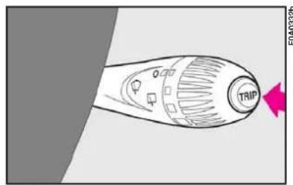
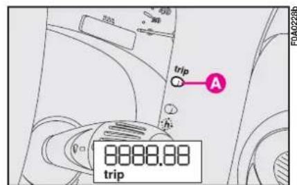
TRIP button fig. 46 and fig. 47 (Natural Power versions)
Button TRIP shall be used (with ignition key at MAR), to display and to reset the previously described values to start a new mission:
– short push to display the different values
- long push to reset and then start a new mission.
New mission
Reset can be:
- “manual” resetting by the user, by pressing the relevant button;
- “automatic” resetting, when the “Trip distance” reaches 3999.9 km or 9999.9 km (according to the type of display) or when the “Travel time” reaches 99.59 (99 hours and 59 minutes);
- after disconnecting/reconnecting the battery.
IMPORTANT The reset operation in the presence of the screens concerning the "General Trip" will also reset the "Trip B". The reset operation in the presence of the screens concerning the "Trip B" makes it possible to reset only the information associated with this function.
text_image
TRIP F0A03326fig. 46
text_image
60 0 30 trip A 8888.88 tripfig. 47
Start of journey procedure
With ignition key at MAR, press and keep button TRIP pressed for over 2 seconds to reset.

flowchart
graph TD
    A["Reset GENERAL TRIP\nEnd of complete mission\nStart of new mission"] --> B["TRIP B"]
    B --> C["Reset TRIP B\nEnd of partial mission\nStart of new partial mission"]
    C --> D["General TRIP\nReset TRIP B\nEnd of partial mission\nStart of new partial mission"]
    D --> E["TRIP B"]
    E --> F["Reset TRIP B\nEnd of partial mission\nStart of new partial mission"]
    F --> G["General TRIP\nReset TRIP B\nEnd of complete mission\nStart of new mission"]
fig. 48
WARNING LIGHTS AND MESSAGES
GENERAL INFORMATION
Turning on of warning light is accompanied by specific message and/or by buzzer sound where provided by instrument panel. These indications are concise and cautionary and shall not be considered as exhaustive and/or as an alternative to the specifications contained in this Owner Handbook which shall always be read through carefully and thoroughly. In case of failure indication always refer to the specifications contained in this section.
IMPORTANT Failure indications displayed are divided into two categories: very serious and less serious failures.
Very serious failures are indicated by a warning “cycle” repeated until failure is eliminated.
Less serious failures are indicated by a limited warning "cycle".
The warning cycle of both failure categories can be stopped by pressing button MODE. The instrument panel warning light will stay on until eliminating the fault.

Turning the ignition key to MAR the warning light turns on, but it should go off after few seconds.
Low brake fluid level
The warning light turns on when the level of the brake fluid in the reservoir falls below the minimum level, due to possible leak in the circuit.
On certain versions the dedicated message is displayed.

If the warning light Ⓑ turns on when travelling (on certain versions to-
gether with the message on the display) stop the vehicle immediately and contact Fiat Dealership.
Handbrake on
The warning light turns on when the handbrake is on.
On certain versions, if the vehicle is moving the buzzer will also sound.
IMPORTANT If the warning light turns on when travelling, check that the handbrake is not engaged.

AIR BAG FAILURE (red) (where provided)
Turning the ignition key to MAR the warning light turns on, but it should go off after few seconds.
The warning light stays on glowing steadily if there is a failure in the air bag system.
On certain versions the dedicated message is displayed.

If when turning the ignition key to MAR, the warning light ⚡ does not turn on or stays on when travelling there could be a failure in safety systems; in this event air bags or pretensioners could not trigger in case of impact or, in a minor number of cases, they could trigger accidentally. Contact Fiat Dealership immediately to have the system checked.

The failure of the warning light ⚙ (warning light off) is also indicated by the flashing for more than the normal 4 seconds of the passenger's front air bag deactivated warning light 🏠.

HIGH TEMPERATURE ENGINE COOLANT FLUID (red)
Turning the ignition key to MAR the warning light turns on, but it should go off after few seconds.
The warning light turns on when the engine is overheated.
If the warning light comes on, proceed as follows:
- normal driving conditions: stop the vehicle, switch off the engine and check whether the water level in the reservoir is not below the MIN mark.
Otherwise wait for few seconds to allow the engine cooling, then open slowly and carefully the cap, top up coolant and check whether its level is falling between MIN and MAX marks in the reservoir. Check visually any leak. If, when restarting, the warning light comes on again, contact Fiat Dealership.
- vehicle heavy duty (e.g.: towing trailer uphill of fully laden vehicle): decrease speed, if the warning light stays on, stop the vehicle. Wait for 2 or 3 minutes leaving the engine on and slightly accelerated to further activate the circulation of the coolant fluid, then switch the engine off. Check proper coolant level as described previously.
IMPORTANT Under severe use of the vehicle, keep the engine on and slightly accelerated for few minutes before switching it off. On certain versions the dedicated message is displayed.

LOW BATTERY CHARGE (red)
Turning the ignition key to MAR the warning light turns on, but it should go out as soon as the engine is started (with the engine running at idle speed a brief delay in going out is allowed).
If the warning light stays on, contact immediately Fiat Dealership.

EBD FAILURE (red) (amber)
The turning on at the same time of warning lights ⏻ and Ⓐ with the engine running indicates an EBD system failure or that the system is unavailable; in this case heavy braking may cause the rear wheels to lock before time, with the possibility of skidding.
Drive with the utmost care to the nearest Fiat Dealership to have the system checked.
On certain versions the dedicated message is displayed.
LOW ENGINE OIL PRESSURE (red)
EXHAUST OIL (Multijet versions) (red)
Low engine oil pressure
Turning the ignition key to MAR the warning light turns on, but it should go out as soon as the engine is started.
On certain versions the dedicated message is displayed.
If the warning light turns on when the vehicle is travelling (on certain versions together with the message on the display) stop the engine immediately and contact a Fiat Dealership.
Exhaust oil (Multijet versions)
The warning light with turn on flashing together with the message on the display when the system detects that the engine oil is exhaust.
After the initial signalling, each time the engine is started, the warning light will continue to flash cyclically for 3 minutes with intervals of 5 seconds with the warning light OFF until the oil is changed.

If warning light is flashing, go to a Fiat Dealership immediately to have the engine oil
changed and the warning light in the instrument panel will go out. Failure to do so may adversely affect the validity of the warranty.
SEAT BELTS NOT FASTENED (red)
The warning light on the dial turns on glowing steadily with vehicle stationary and driver's or passenger's seat belt not fastened correctly. The warning light will turn on flashing when, with vehicle moving, driver's or passenger's seat belt are not fastened correctly.

INCOMPLETE DOOR LOCKING (red)
On certain versions the warning light turns on when one or more doors or the tailgate are not properly shut.
On certain versions the dedicated message is displayed; symbols ◀/▶ indicate respectively left / right door open.
A buzzer will sound when doors/tailgate are open and the vehicle is moving (only for versions with reconfigurable multifunction display).
INJECTION SYSTEM FAILURE (Multijet versions - amber)
EOBD SYSTEM FAILURE (petrol versions - amber)
Injection system failure
Turning the ignition key to MAR the warning light turns on but it should go off after engine starting.
If the warning light stays on or turns on when travelling, means a fault in the supply/ignition system which could cause high emissions at the exhaust, possible lack of performance, poor handling and high consumption levels.
On certain versions the dedicated message is displayed.
In these conditions it is possible to continue driving without however requiring heavy effort or high speed from the engine. In any case, contact Fiat Dealership as soon as possible.
EOBD engine control system failure
Under normal conditions, turning the ignition key to MAR, the warning light turns on, but it should go out as soon as the engine is started. The initial turning on indicates that the warning light is working properly. If the warning light stays on or turns on when travelling:
– glowing steadily: means a fault in the supply/ignition system which could cause high emissions at the exhaust, possible lack of performance, poor handling and high consumption levels.
On certain versions the dedicated message is displayed.
In these conditions it is possible to continue driving without however requiring heavy effort or high speed from the engine. Prolonged use of the vehicle with the warning light on may cause damages. Contact Fiat Dealership as soon as possible. The warning light goes off if the fault disappears, but it is still stored by the system.
- flashing: indicates the possibility of damage to the catalyst (see "EOBD system" in this section).
If the light flashes, it is necessary to release the accelerator pedal to lower the speed of the engine until the warning light stops flashing; continue the journey at moderate speed, trying to avoid driving conditions that may cause further flashing and contact Fiat Dealership as soon as possible.

If, turning the ignition key to MAR, the warning light ☐ does not turn on or if it turns on glowing steadily or flashing when travelling (on certain versions together with the message on the display), contact Fiat Dealership as soon as possible. Warning light operation can be checked by traffic agents by proper equipment. Comply with laws and regulations of the country where you are driving.

Turning the ignition key to MAR the warning light turns on, but it should go off after few seconds.
The warning light turns on when about 5-7 litres fuel are left in the tank.
IMPORTANT The warning light flashes to indicate a failure, contact Fiat Dealership as soon as possible to have the system checked.
On certain versions the dedicated message is displayed.
INEFFICIENT ABS SYSTEM (amber)
Turning the ignition key to MAR the warning light turns on, but it should go off after few seconds.
The warning light turns on when the system is inefficient or unavailable. In this case the braking system keeps its effectiveness unchanged, but without the potential offered by the ABS system. Caution is advisable and it is necessary to contact Fiat Dealership.
On certain versions the dedicated message is displayed.

FRONT PASSENGER'S AIR BAG DEACTIVATED (amber)
Warning light 🖼️ comes on when front passenger's air bag is deactivated.
With front passenger's air bag on, turning the ignition key to MAR, warning light ⚙️ comes on steadily for about 4 seconds, it flashes for other 4 seconds and then it shall go off.

Warning light 📊 indicates also warning light failures. This is indicated by intermittent flashing, over 4 seconds, of warning light ⚡. In this event warning light ⚡ indicates that there could be a failure in safety systems. Contact Fiat Dealership immediately to have the system checked.

GLOW PLUG WARMING
(Multijet versions - amber)
GLOW PLUG WARMING FAIL-URE (Multijet versions - amber)
Spark plug pre-heating
Turning the ignition key to MAR, the warning light turns on and it will turn off when glow plugs reach the preset temperature. Start the engine immediately after warning light switching off.
IMPORTANT With hot ambient temperature, warning light stays on for very short time.
Glow plug warming failure
The warning light turns on when there is a failure in the glow plug warming system. Contact Fiat Dealership as soon as possible.
On certain versions the dedicated message is displayed.

WATER IN DIESEL FUEL FILTER
(Multijet versions - amber)
Turning the ignition key to MAR the warning light turns on, but it should go off after few seconds. The warning light ☐ turns on when there is water in the diesel fuel filter. On certain versions the warning light △ turns on and the display shows a dedicated message.

The presence of water in the fuel circuit may cause serious damage to the entire injection system and cause irregular engine operation. If the warning light ☐ or △ turns on (on certain versions together with the message on the display) contact Fiat Dealership as soon as possible to have the system relieved. If the above indications come on immediately after refuelling, water has probably been poured into the tank: turn the engine off immediately and contact Fiat Dealership.

VEHICLE PROTECTION SYSTEM FAILURE - FIAT CODE (amber)
Turning the key to MAR the warning light shall flash only once and then go off.
If with the ignition key at MAR, the warning light stays on, this indicates a possible failure (see "Fiat Code system" in section "Dashboard and controls").
IMPORTANT The turning on at the same time of the warning lights 📄 and Y indicates a failure of the Fiat CODE system.
If with the engine running the warning light ☐ flashes, this means that the vehicle is not protected by the engine inhibitor device (see “Fiat Code system” in section “Dashboard and controls”).
Contact Fiat Dealership to have all the key memorised.

HEATED REAR WINDOW (amber)
The warning light turns on when switching the heated rear window on.

EXTERNAL LIGHT FAILURE (amber)
The warning light turns on when one of the following lights is failing:
- sidelights
- brake lights (third brake light excluded)
- rear fog guards
– direction indicators
– number plate lights.
The failure referring to these lights could be: one or more blown bulbs, a blown protection fuse or an electric connection cut-off.
On certain versions the dedicated message is displayed; symbols ◀ / ▶ indicate respectively the left / right side.

REAR FOG LIGHTS (amber)
The warning light turns on when the rear fog lights are turned on.

DIESEL PARTICULATE FILTER CLOGGED
(1.3 Multijet 85 HP and 1.9 Multijet 120 HP versions) (Amber)
The warning light turns on when the diesel particulate filter is clogged and the driving conditions do not enable to activate automatically the reclaiming procedure.
To enable the cleaning procedure, keep the vehicle running until the warning light turns off.
The display will show the dedicated message.

Warning light 📋 turns on together with the dedicated message on the display to indicate that the cleaning procedure cannot be performed, contact Fiat Dealership as soon as possible.

GENERIC FAILURE INDICATION amber)
The warning light turns on in the following circumstances.
Engine oil pressure sensor failure
The warning light comes on when the engine oil pressure sensor is faulty. Contact Fiat Dealership as soon as possible.
On certain versions the dedicated message is displayed.
Speed limit exceeded
The display will show the dedicated message when the vehicle exceeds the set speed limit (see “Reconfigurable Multifunction Display” in this section).
On certain versions the dedicated message is displayed.
Diesel fuel filter sensor failure
The warning light comes on when the diesel fuel filter sensor is faulty. Contact Fiat Dealership as soon as possible.
On certain versions the dedicated message is displayed.
Water in diesel fuel filter
See what described for warning light

SIDELIGHTS AND LOW BEAMS (green)
FOLLOW ME HOME (green)
Side/taillights and low beams
The warning light turns on when side/taillights or low beams are turned on.
Follow me home
The warning light will turn when this device is active (see “Follow me home” in section “Dashboard and controls”).
The display will show the dedicated message.

FRONT FOG LIGHTS (green)
The warning light turns on when the front fog lights are turned on.

LEFT-HAND DIRECTION INDICATOR (green - intermittent)
The warning light turns on when the direction indicator control lever is moved downwards or, together with the right indicator, when the hazard warning light button is pressed.

RIGHT-HAND DIRECTION INDICATOR (green - intermittent)
The warning light turns on when the direction indicator control lever is moved upwards or, together with the left indicator, when the hazard warning light button is pressed.

LEFT-HAND AND RIGHT-HAND DIRECTION INDICATOR (green - intermittent) (Natural Power versions)
The warning light turns on when the direction indicator control lever is moved downwards or, together with the right indicator, when the hazard warning light button is pressed.
The warning light turns on when the direction indicator control lever is moved upwards or, together with the left indicator, when the hazard warning light button is pressed.

MAIN BEAMS (blue)
The warning light turns on when the main beams are turned on.
POSSIBLE PRESENCE OF ICE ON THE ROAD
(versions with reconfigurable multifunction display)
This indication starts flashing when the outside temperature reaches or falls below 3^ C to warn the driver of the possible presence of ice on the road.
The display will show the dedicated message.
LIMITED RANGE
(versions with reconfigurable multifunction display)
The display will show the dedicated message to warn the driver that the cruising range is less than 50 km.
INDIVIDUAL SETTINGS
DRIVER'S SEAT

Only make adjustments when the vehicle is stationary.
Moving the seat backwards or forwards
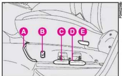
Lift the lever A-fig. 50 and push the seat forwards or backwards. You are in the correct position for driving when your hands are resting on the steering wheel rim and your arms are slightly bent.

Once you have released the lever, check that the seat is firmly locked in the runners by trying to move it back and forth. Failure to lock the seat in place could result in the seat moving suddenly and dangerously.
Adjusting the reclining seat back
Lift lever E-fig. 50.
text_image
A B C D E F0A0258bfig. 50
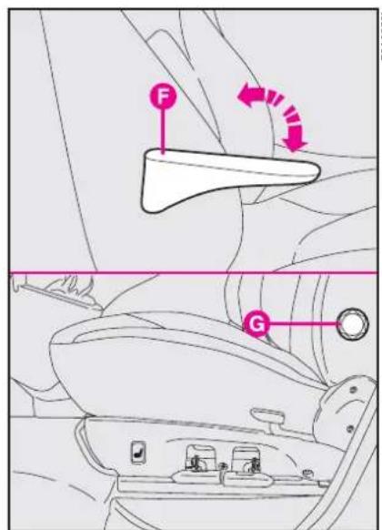
Driver's seat with armrest and adjustable lumbar support fig. 51
The armrest can be lifted or lowered F.
The lumbar support can be adjusted to better support you back. Turn knob G to adjust.
text_image
F Gfig. 51
Electrically heated driver's seat fig. 50
Press button B to switch the seat heating on and off.
The LED on the button will light up when the function is on.
Height adjustment
Move lever C-fig. 50 upwards to raise the front seat section and move lever D upwards to raise the rear seat section. Move the levers downwards to lower the seat.
IMPORTANT The seat shall not be occupied when raising, whereas you must be seated when lowering it.

Only make adjustments when the vehicle is stationary.
FIXED PASSENGER SEAT
Adjusting the reclining seat back
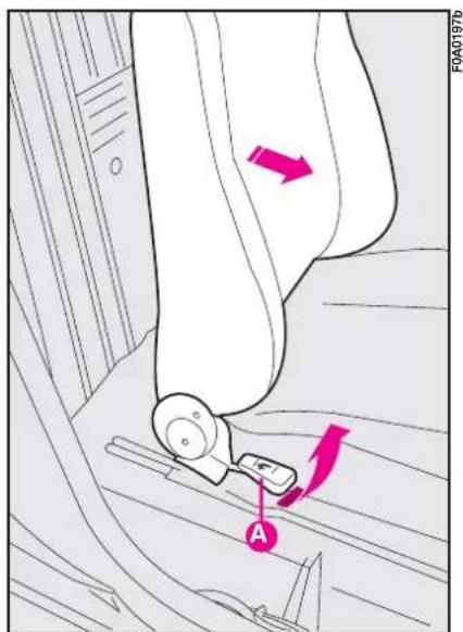
Lift lever A-fig. 52.
text_image
F0A0197b Afig. 52
SLIDING PASSENGER SEAT
Adjusting the reclining seat back
Lift lever A-fig. 52.
Moving the seat backwards or forwards
Lift lever B-fig. 53 and push the seat backwards or forwards.
Once you have released the lever, check that the seat is firmly locked in the runners by trying to move it back and forth. Failure to lock the seat in place could result in the seat moving suddenly and dangerously.
FOLDING FRONT PASSENGER SEAT
Folding the seat back
Lift lever A-fig. 54 to fold the seat back and obtain a tabletop.
Tipping the seat
To tip the seat and make more space in the passenger compartment proceed as follows:
- tip the seat as described previously;
- use lever B-fig. 55 to tip the whole seat forward;
- lock the seat using the special rod A-fig. 56 and fitting it into slot B on the seat.
To return the seat to normal position, release rod A and then raise the seat.
IMPORTANT When folded, the seat shall be anchored by the proper rod ' to prevent its violent returning to original position when accelerating.
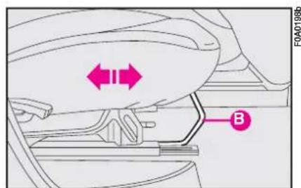
text_image
F0A0198b Bfig. 53
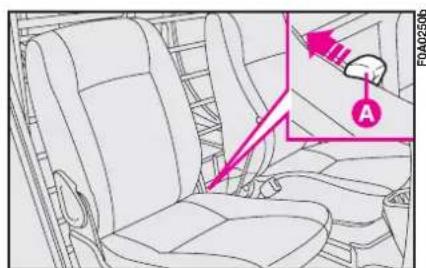
text_image
FA042506 Afig. 54
PARTITIONS
Fixed panel partition
Certain Fiat Doblò Cargo panelled versions fit a fully panelled partition.
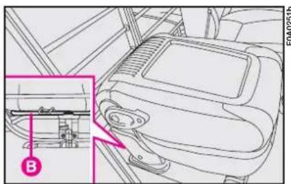
text_image
Technical diagram of a car interior with labeled component B, showing dashboard and seat area with highlighted parts.fig. 55
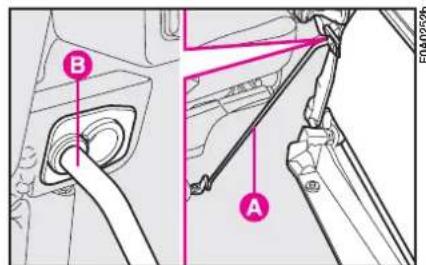
text_image
Technical diagram showing car interior components with labeled parts A and B, likely for vehicle assembly or maintenance instructions.fig. 56
Fixed partition with window
Certain Fiat Doblò Cargo panelled versions fit a fixed panel with central window through which stability of the load in the compartment can be checked.
Driver's protection ladder
Certain Fiat Doblò Cargo versions fit a fixed ladder for protecting the driver if the load in the compartment is unstable.
Double ladder
Certain Fiat Doblò Cargo versions fit a split ladder for protecting the driving if the load in the compartment is unstable and allows to extend loading space on passenger side.
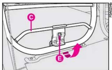
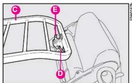
Fastening the ladder: Tip the seat as described previously, release the ladder C-fig. 57 from its housing using lever E and fasten it to handle D-fig. 58 on the seat. Make sure it is fastened well.
IMPORTANT When folded, the seat shall be anchored to the ladder to prevent its violent returning to the original position when accelerating.
text_image
C E FA0254bfig. 57
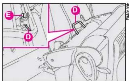
Releasing the ladder: press button E-fig. 59 to release the ladder from the handle D. Reposition the ladder in its original position. Tip the seat by lowering the cushion and lifting the seat back. Make sure that the seat is locked.

The ladder shall only be tilted with the vehicle stationary and the door
open.
ACCESSING THE REAR SEATS
Versions with one sliding side door (on passenger side)
From passenger's side: open the sliding side door.
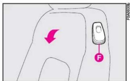
From driver's side: pull handle F-fig. 59a upwards to tip the seat back.
Once you have let go of the lever, check that the seat is firmly locked in the runners by trying to move it back and forth.

In the event of an emergency, you can get out of the rear seats from the side by tilting the driver's
Versions with two sliding side doors
Open either of the two sliding side doors to access the rear seats.

You cannot open the left-hand sliding side door while refuelling when the open (see "At the filling" in this section).
text_image
C E D FOA01875fig. 58
text_image
E D D FOA0199bfig. 59
text_image
FOA06000 ↓ C Ffig. 59a
7-seat versions
To access the third row:
– open the side sliding door;
– lower the head restraints (if set in the normal position of use) (see paragraph "Head restraints");
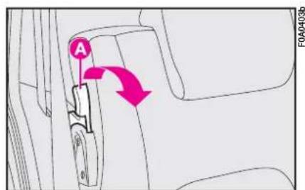
- release lever A-fig. 59b and fold the seat forward onto the cushion;
- raise the whole cushion fig. 59c.
To get out of the vehicle, reverse the above operations and make sure head restraints are lowered.
IMPORTANT It is forbidden to travel with the second row seats tipped and third row seats set in normal position of use. More particularly, if the central seat of the second row is tipped and that of the third row is set in normal position of use, a buzzer will sound to indicate the wrong seat position.
TAILGATE EMERGENCY OPENING
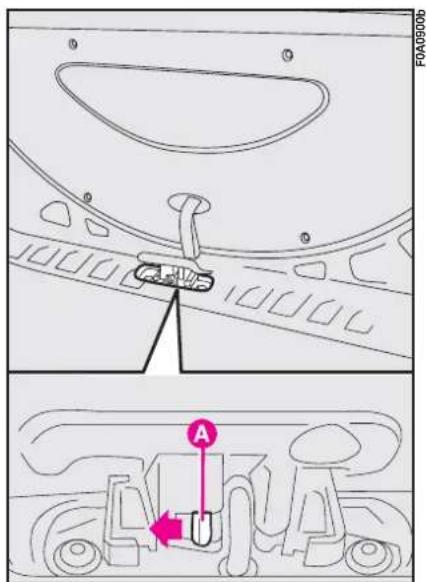
On versions with front seats that do not fold over, there is an opening device inside the tailgate to allow the occupants to evacuate the rear seats in an emergency. To unlock the tailage, operate device A illustrated in the fig. 60 from inside the load compartment.

It is absolutely forbidden to travel with the second row seats tipped and pas-
sengers seated on the third row seats (as specified on the seat label).
text_image
A FOA0403bfig. 59b

natural_image
Technical line drawing of a vehicle's seat assembly and steering wheel (no text or symbols)fig. 59c
text_image
F0A09006 Afig. 60
HEAD RESTRAINTS
Front seats
According to the version, the head restraints can be:
- fixed fig. 61;
- adjustable in height fig. 61a.
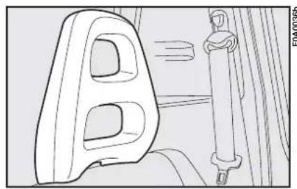
natural_image
Line drawing of a car seatbelt with a side-mounted cable, showing no text or symbolsfig. 61
To adjust, move the head restraint upwards or downwards until it clicks.
Make sure it is properly locked in place.
Fixed head restraints cannot be removed.
Rear seats, 5-seat versions
The height of the rear head (where provided) restraints can be adjusted fig. 62.
To remove the rear head restraints, remove the rear window shelf (see "Boot" in this chapter), press buttons A-fig. 62 by the side of the stands and pull the head restraint upwards.
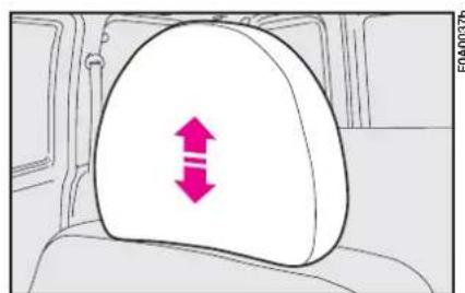
text_image
FOA00376fig. 61a
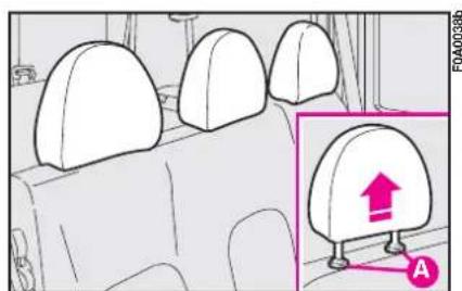
natural_image
Interior view of a car showing three seats with a highlighted seat labeled 'A' and an upward arrow (no text or symbols on the seats)fig. 62
Remember that the head restraints should be adjusted to support the back of your head and not your neck. Only if they are in this position will they be able to provide effective protection.
Rear seats, 7-seat versions
Head restraints for rear seats are mobile fig. 62a. To use head restraints, raise them from non-use position (1) to use position (2). To set them back to "non-use position" (1), press the outer button A-fig. 62b and push down the head restraint. Rear head restraints can be removed; to remove them: press buttons A and B and then raise them to complete removal.

text_image
FOA0414b ② ①fig. 62a

Only make adjustments when the vehicle is stationary.
The particular head restraint shape voluntarily interferes with the passenger's back leaning on the rear seat in order to force him/her to lift the head restraint and use it correctly.
IMPORTANT Rear passengers shall always set head restraints to position (2) when travelling.
HEIGHT ADJUSTABLE STEERING WHEEL
In certain versions, the steering wheel can be adjusted vertically:
I) Move lever A-fig. 63 to position I.
2) Adjust the steering wheel.
3) Take the lever back to position 2 to fasten the steering wheel.
DRIVING MIRROR
This mirror can be adjusted by means of lever A-fig. 64
I) anti-dazzle position.
2) normal position.
The mirror is also fitted with a safety device that releases the mirror in the event of an impact.

Only make adjustments when the vehicle is stationary.
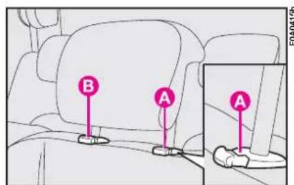
text_image
B A Afig. 62b
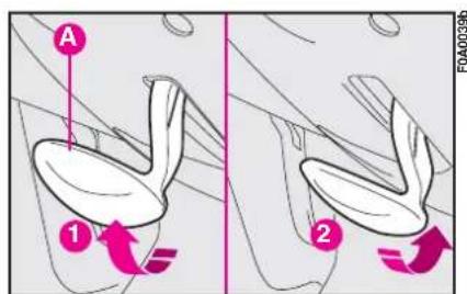
text_image
A 1 2 FOA00396fig. 63
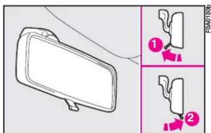
text_image
① ②fig. 64
DOOR MIRRORS
Manual adjustment from the outside fig. 65
Open the window and move mirror A directly with your hands.
Manual adjustment from the inside fig. 66
Turn knob A from inside the vehicle.

If the mirror makes it difficult to get through narrow gaps, fold it from n I to position 2.
Electrical adjustment fig. 67
This operation is only possible with ignition key at MAR.
Press switch A in the four directions to adjust the mirror as required.
Use switch B to select the mirror (left-hand or right-hand) you want to adjust.
You should adjust the mirrors when the vehicle is stationary and with the handbrake engaged.
The electrical mirror demisting device will be switched on automatically with the heated rear window.
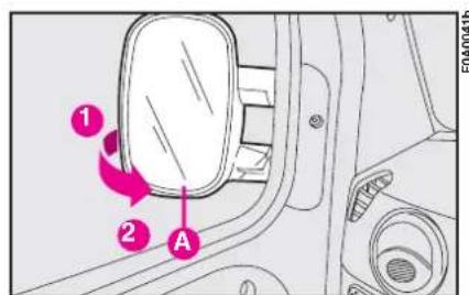
text_image
1 2 A FOA0041bfig. 65
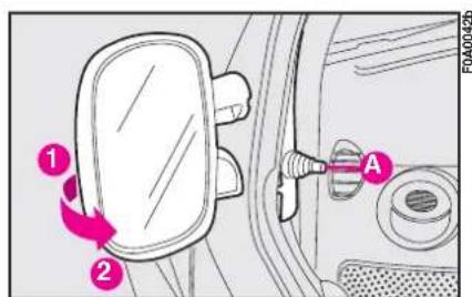
text_image
Diagram showing car door panel with labeled parts and directional arrows indicating movement or adjustment.fig. 66
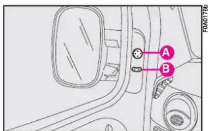
text_image
A B FOA0178bfig. 67
HEATING AND VENTILATION SYSTEM
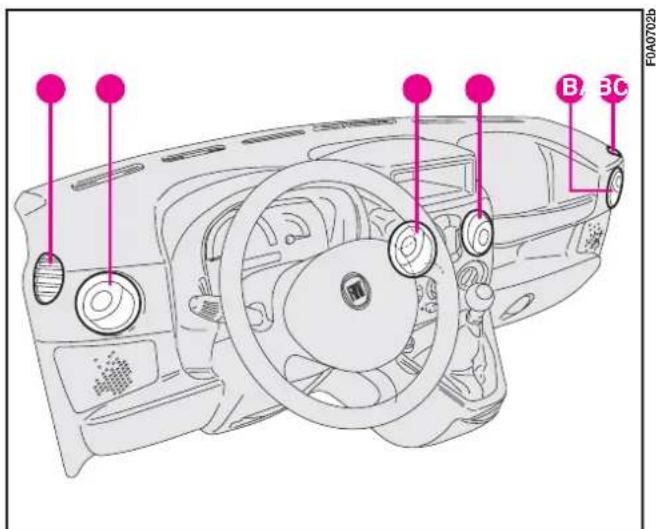
text_image
F0A0702b B 3CFig. 68 - Version with central unit
A. Fixed side vents - B. Adjustable side vents - C. Adjustable central vents
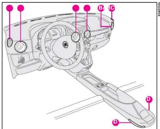
text_image
B/3C FA0703b D DFig. 69 - Version with central tunnel
A. Fixed side vents - B. Adjustable side vents - C. Adjustable central vents - D. Rear seat lower vents.
CENTRAL VENTS fig. 70
A - Left-hand rocking vent.
B - Left-hand rocking vent.
Press and turn vents A and B directly to adjust the air flow and direction.
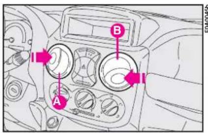
text_image
A B FA00456fig. 70
SIDE VENTS fig. 71
A - Adjustable vent: press as shown by the arrow and direct as required.
B - Fixed side window vent.
CONTROLS fig. 72
A - Fan knob.
B - Recirculation slider, to cut out outside air.
C - Air temperature knob (warm/cool air mixer).
D - Air distribution knob.
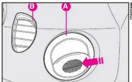
text_image
B Afig. 71
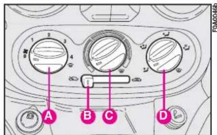
text_image
A B C Dfig. 72
CLIMATIC COMFORT
Air distribution
Knob D-fig. 72 directs the air inside the passenger compartment according to five levels:
conveys the air to the central and side vents directly to the body (face/chest);
conveys warmer air to the lower vents and cooler air to the central vents and dashboard vents (bilevel);
√ exploits the characteristic of warm air to move upwards ensuring a faster warming of the passenger compartment;
√ ensures good passenger compartment warming and prevents misting up at the same time;

all the air is conveyed to the wind-screen and front side windows for demisting and defrosting.
The distribution levels are graphically illustrated in the following figures.
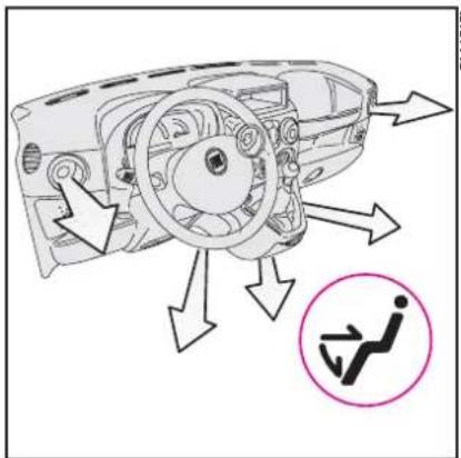
text_image
Diagram showing car interior airflow with directional arrows and a highlighted safety symbol for vehicle use.fig. 74
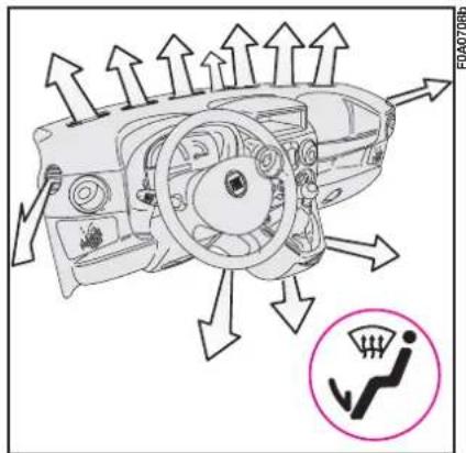
text_image
Diagram of car air intake system with directional arrows and a warning symbol for vehicle safety.fig. 76
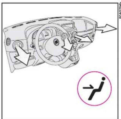
text_image
Diagram of a car interior showing directional arrows and a traffic sign with a right-angle symbolfig. 73
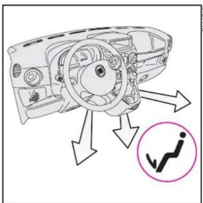
text_image
Diagram of car air intake system with directional arrows and a checkmark icon indicating traffic flowfig. 75
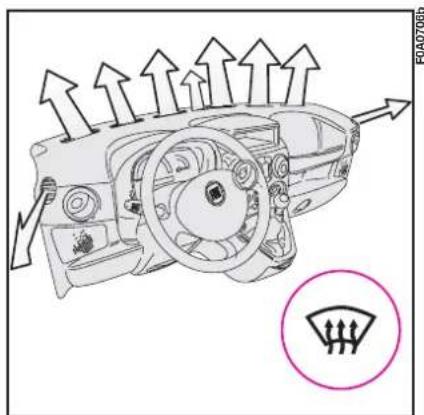
text_image
Diagram of a car interior showing airflow direction and a highlighted fan-shaped gauge with three blades.fig. 77
Heating
I) Air temperature knob C: pointer in the red sector.
2) Fan knob A: pointer at the required speed.
3) Air distribution knob D: pointer at
to warm the feet and demist the windscreen at the same time;
to convey air to the feet and cooler air to the central vents and dashboard vents;
√ for fast heating.
Fast heating
I) Close the vents on the dashboard.
2) Air temperature knob A: pointer at ⬤ in the red sector.
3) Fan knob A at fourth speed, pointer at 4.
4) Air temperature knob D: pointer at √.
Demisting and defrosting the windscreen and the front side windows
This function - called max-def - is obtained by turning the control pointers to the orange symbols, specifically:
I) Air temperature knob A: pointer at ⏻ in the red sector.
2) Fan knob B: pointer at top speed 4.
3) Air distribution knob D: pointer at 🌐.
4) Slider B at 📄.
After demisting and/or defrosting, operate the controls to restore the required comfort.
To prevent misting up:
IMPORTANT If the outside air is very damp, if it is raining and/or if there is a considerable difference between temperature inside and outside the vehicle, prevent the windows from misting up as follows:
– slider B at 📄;
— air temperature knob C: pointer at in the red sector;
- fan knob A at second speed or faster, pointer at 2;
- air distribution knob D: pointer at ☑; switch to √ if the windows start misting up.
If the vehicle has a climate control system, you are recommended to adjust the controls as described above and press button A-fig. 78 to speed up the demisting process.
Demisting and defrosting the rear window/s
Press button. The electric mirror demisting device also comes on.
Warning light D on the instrument panel will turn on.
You are advised to switch the button off as soon as the rear window is clear.
Ventilation
I) Centre and side vents: completely open.
2) Air temperature knob C: pointer in the blue sector.
3) Slider B at 📄.
4) Fan knob A: pointer at the required speed.
5) Air distribution knob D: pointer at 7.
Recirculation
With the slider B at 📄 the internal air is recirculated.
IMPORTANT This function is particularly useful when the outside air is heavily polluted (in a traffic jam, tunnel, etc.) and when running on dusty roads. You are advised against using this function for long periods, however, especially if there are a lot of people in the vehicle or on cold or rainy days since the windows could mist up effecting visibility and driving.
MANUAL CLIMATE CONTROL SYSTEM (where provided)
The climate control system is adjusted manually.
CONTROLS fig. 78
A - Knob for operating the fan and switching the climate control system on and off.
The climate control system can only be switched on when the pointer on this knob is at speed 1, 2, 3 or 4, the led on the knob will light up when the system is on.
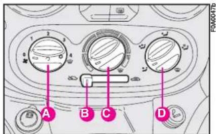
text_image
A B C Dfig. 78
Consequently, the climate control system cannot be switched on when the pointer is at 0 ♣.
B - Recirculation slider, to cut out outside air.
IMPORTANT This function is particularly useful when the outside air is heavily polluted (in a traffic jam, tunnel, etc.) and when running on dusty roads. You are advised against using this function for long periods, however, especially if there are a lot of people in the vehicle or on cold or rainy days since the windows could mist up effecting visibility and driving.
C - Air temperature knob (warm/cool air mixer).
D - Air distribution knob.
The system uses refrigerating fluid RI34a which will not pollute the environment if it accidentally leaks. Under no circumstances should fluid RI2 be used as this is incompatible with the system's component parts.
CLIMATIC COMFORT
See previous chapter for air distribution and heating/ventilation functions.
IMPORTANT The manual climate control system is very useful for speeding up the demising process because it dries the air. Simply adjust the controls for the demisting function (see previous section) and switch the manual climate control system on by pressing knob A-fig. 78.
Maximum cooling
I) Air temperature knob C: pointer in the blue sector.
2) Fan knob A at fourth speed, pointer at 4.
3) Slider B: at
4) Air distribution knob D: pointer at 7.
5) Climate control system: press knob C-fig. 78.
To moderate the cooling effect: position slider B at 📋, increase the temperature and reduce the fan speed.
LOOKING AFTER THE SYSTEM
During the winter, the climate control system must be turned on at least once a month for about ten minutes.
Have the system efficiency checked before the summer at a Fiat Dealership.

The system is filled with R134a refrigerant which will not pollute the envi-
ronment in the event of leakage. Under no circumstances should R12 fluid be used as it is incompatible with the system components and contains CFC.
STEERING COLUMN STALKS
LEFT-HAND STALK
The left-hand stalk operates most of the external lights.
The external lights can only be switched on when the ignition key is at MAR. The instrument panel and the heating/ventilation (or climate control system) controls and the cigar lighter ring will come on with the external lights.
Side/taillights fig. 79
These come on when you turn the ring from O to ⚙. Instrument panel warning light ≧00≤ will come on.
Dipped beam headlights fig. 80
These come on when you turn the knurled switch from ⚙️ to ⏱.
IMPORTANT The dipped beam headlights will automatically be switched off when the main beam headlights are switched on if the front fog lights are on.
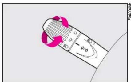
natural_image
Close-up of a mechanical component with pink arrows indicating rotation or motion, no visible text or symbolsfig. 79
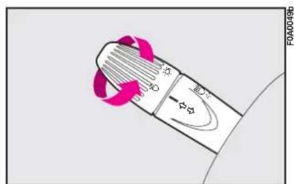
text_image
Diagram showing a device with labeled ports and directional arrows, likely indicating flow or movement in a control or control system.fig. 80
Main beam headlights fig. 81
Push the stalk from position 📊 towards the dashboard to switch the headlights on.
Warning light D on the instrument panel will turn on.
Pull the stalk towards the steering wheel to switch the lights off.
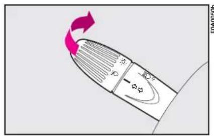
text_image
Diagram showing airflow around a device with directional arrows and labeled componentsfig. 81
Flashing the headlights fig. 82
Pull the stalk towards the steering wheel (unstable position).
Warning light ☑ on the instrument panel will turn on.
Direction indicators fig. 83
Move the stalk as follows:
up - to switch on the right-hand direction indicator
down - to switch on the left-hand direction indicator.
Instrument panel warning light ⇔ ⇔ or ⇔ and ➤ will come on flashing.
The direction indicators will automatically be switched off when the vehicle is straightened out.
If you wish to signal a lane change where only a slight movement of the steering wheel is required, move the stalk up or down without pushing it far enough to make it click. The stalk will return to the neutral position as soon as it is released.
RIGHT-HAND STALK
Windscreen wiper/washer fig. 84
The device will only work when the ignition key is at MAR.
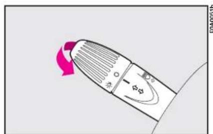
text_image
FOA0051bfig. 82
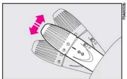
text_image
F0A00526fig. 83
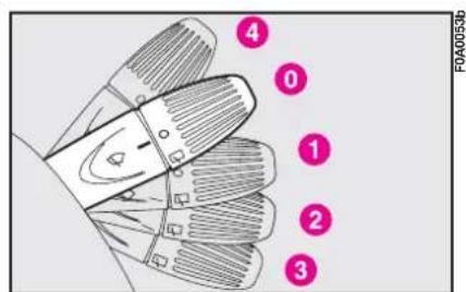
text_image
FOA0053b ④ ① ② ③ ④fig. 84
POSITIONS fig. 84
0 - windscreen wiper off;
I - flick wipe; in some versions, four selections are possible (from slow to fast fig. 85);
2 - slow flick;
3 - fast continuous wipe
4 - Temporary position: when released the stalk returns to 0 and automatically switches off the windscreen wiper.
SMART WASH for rear window wiper fig. 86
Pull the stalk towards the steering wheel to send a jet of fluid to the windscreen and operate the wiper with a simple gesture. The windscreen wiper will be operated automatically by holding the washer stalk for longer than half a second.
The windscreen wiper will flick three times after the lever is released.
Operate the control repeatedly and rapidly (for less than half a second) to spray the windscreen several times without operating the windscreen wiper.
Rear window washer/wiper (with glazed rear doors/tailgate) fig. 87-88
The device will only work when the ignition key is at MAR.
To operate the rear window wipe: turn the ring from ○ to □.
To wash the window push the stalk towards the dashboard.
SMART WASH for windscreen wiper fig. 88
Pull the stalk towards the steering wheel to send a jet of fluid to the rear window and operate the wiper with a simple gesture. The rear window wiper will be operated automatically by holding the washer stalk for longer than half a second.
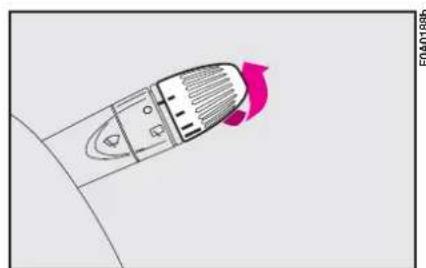
natural_image
Top-down schematic of a car interior with highlighted seat area (no text or symbols)fig. 85
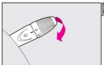
natural_image
Diagram of a device with a curved arrow indicating rotation or change (no text or symbols)fig. 86
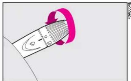
natural_image
Diagram of a mechanical component with a pink circular arrow indicating rotation or force application (no text or symbols)fig. 87
The rear window wiper will flick three times after the lever is released.
"FOLLOW ME HOME" function
This function allows the illumination of the space in front of the vehicle.
Turning the function on
With the ignition key at STOP or removed, pull the left-hand stalk towards the steering wheel and operate it within 2 minutes from when the engine is turned off.
At each single movement of the stalk, the staying on of the lights is extended by 30 seconds up to a maximum
of 210 seconds; then the lights are switched off automatically.
Each time the lever is operated, the warning light ≥00 on the instrument cluster will come on and the display will show the time of activation.
The warning light comes on the first time the lever is operated and will stay on up to automatic function deactivation. Each operation of the lever will extend lights switching on time.
Turning the function off
Keep the stalk pulled towards the steering wheel for more than 2 seconds.
CEILING LIGHT
WITH MAP READING LIGHTS
Press switch A-fig. 90 to switch the lights on and off.
Switch B operates the map-reading light.
According to the position, you can have the following conditions:
- switch A pressed at the centre, ceiling lights C and D will come on regardless of the position of the doors;
- switch A pressed to the left, ceiling lights C and D will stay off regardless of the position of the doors;
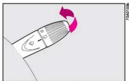
natural_image
Illustration of a handheld device with a pink circular arrow indicating rotation (no text or symbols)fig. 88

text_image
F0A02386bfig. 89
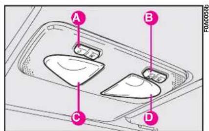
text_image
A B C D F0A0056bfig. 90
- switch A pressed to the right, ceiling lights C and D will stay on in whatever condition.
When the ceiling light is off, switch B turns on the following lights:
- map-reading light C if pressed to the left;
- map-reading light D if pressed to the right.
IMPORTANT Make sure that both switches are in central position before getting out of the vehicle. This is ensure that the ceiling lights go out when the doors are closed preventing the battery from running down.
Timing for getting into the vehicle
The ceiling lights will come on as follows:
- for 15 seconds when the front doors are unlocked;
– for 7 seconds when a door is closed (within the three minutes).
Timing will be stopped when the ignition key is turned to MAR.
Timing for getting out of the vehicle
The ceiling lights will come on as follows when the key is removed from the ignition switch:
– for 3 minutes within two minutes after stopping the engine;
- for 7 seconds when a door is closed (within the three minutes).
Timing will be stopped when the doors are locked.
WITH TOGGLE LENS
Press the short side of the lens fig. 91 to switch the light on and off.
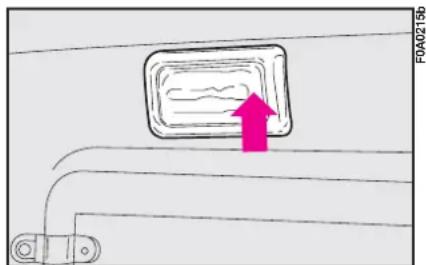
text_image
F0A0215bfig. 91
CONTROLS
HAZARD LIGHTS fig. 92
They turn on by pressing switch A, regardless of the position of the ignition key.
When the lights are on, the switch and the instrument panel warning light ⇔ or ⇔ and → will flash.
Press the switch again to turn the lights off.
The use of hazard lights is governed by the Highway Code of the country you are in. Keep to the rules.
CONTROL BUTTONS fig. 93
The buttons are located between the central air vents.
The controls can only be operated when the ignition key is at MAR.
A - Front foglight button.
B - Rear foglight button.
C - Heated rear window on/off button.
IMPORTANT The dipped beam headlights will automatically be switched off when the main beam headlights are switched on if the front fog lights are on.
The dipped beam headlights and/or the front foglights (if fitted) must be on to switch rear foglights on.
The rear fog lights are switched off either by pressing C or switching on the main beam headlights or turning the ignition key to STOP. You will need to switch the rear foglights back on, if required, when the dipped beam headlights and/or front foglights are switched on or when the engine is started again.
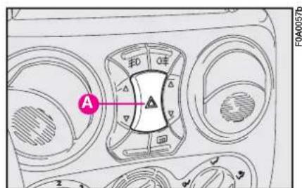
text_image
A F0A0057bfig. 92
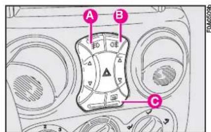
text_image
A B Cfig. 93
FUEL CUT-OFF SWITCH
This safety switch is located under the dashboard on the right-hand side and can be reached through the slot as shown in fig. 94, It comes into operation in the case of an accident to block the supply of fuel thereby stopping the engine.
Press button A to reactivate the fuel supply system if you cannot see any fuel leaks and the vehicle is in a fit state to continue its journey.
Remember to turn the ignition key to STOP to avoid running the battery down.
MAGNETIC CARD POCKET - TICKET POCKET fig. 96 (where provided)
Slots for keeping magnetic cards (telephone cards, etc.) or coins can be found on the central tunnel.

If, after a crash, you smell fuel or see leaks from the fuel system, do
not reset the switch to avoid fire risk.
INTERIOR EQUIPMENT
GLOVEBOX fig. 95
Operate handle A as shown by the arrow to open the compartment.
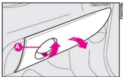
text_image
A FOA0059bfig. 95
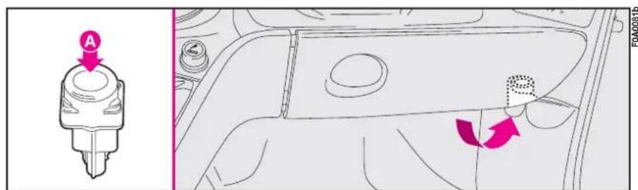
text_image
A F040061bfig. 94
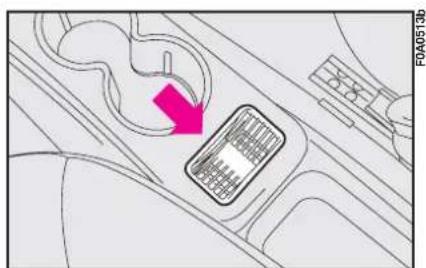
natural_image
Diagram of a car interior with a highlighted vehicle component and directional arrow (no text or symbols)fig. 96
CIGAR LIGHTER fig. 97
With ignition key at MAR: press button A; after approximately 15 seconds it will return to its initial position and is ready for use.
IMPORTANT Always make sure the cigar lighter does in fact pop out after it has been pushed in.

Important. The cigar lighter gets very hot. Handle with care and do children use it: danger of burns.
POWER SOCKET (where provided)
The vehicle is fitted with a power socket A-fig. 98 set on the dashboard (on the left of the gearbox) that only works with ignition key at MAR. Do not use current sockets for accessories with power over 180 W (max. intake 15 A).

Do not use the sockets for accessories with power over the max. specified
one.
Prolonged use of accessories with high current intake could deploy the battery, even preventing the engine from starting.
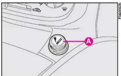
text_image
FA0A0625 Afig. 97
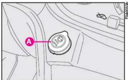
text_image
A FA00053bfig. 98
ASHTRAY fig. 99
Pull flap A towards yourself. Remove the ashtray B by pulling it upwards for emptying it.
Non smokers can remove the ash-tray and use it as additional oddment compartment.
ODDMENT SHELF fig. 100
The shelf is fitted over the sunvisors. It was designed to easily house lightweight objects (e.g. documents, road maps, etc.).
IMPORTANT The shelf was designed for loads not exceeding 3 kg on each side. Consequently, do not arrange objects exceeding these weights. Do not use the points shown as grips fig. 100. Use the specific side handles.
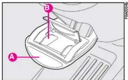
text_image
A B F0A0054bfig. 99
SUN VISORS fig. 101
The sun visors A are positioned to the sides of the rear-view mirror. They can swing up and down, as shown. A ticket pocket can be found on the back of the sunvisor driver's side. A courtesy mirror is applied to the back of the sun visors.
TILTING SHELF (for passengers transport versions, where provided)
Behind the front passenger seatback, it is available (on certain versions) a tilting shelf A-fig. 101a.
To position it horizontally, pull it towards the direction shown by the arrows; reverse this operation to reposition it.
IMPORTANT Do not position on the tilting shelf objects heavier than 3 kg: for safety purposes the shelf is released from its housing when submitted to excessive loads.
Resetting the shelf (after releasing)
Proceed as follows:
- fit the shelf B-fig. 101b so that the support fixed pin A is fitted inside the shelf left rail;
- turn the shelf B until the lower edge is touching the support A mobile pin C;
- press slightly in arrow direction to set the shelf B in the position of use. Pin C is inside the shelf right rail.
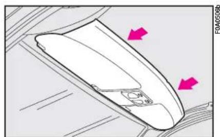
natural_image
Line drawing of a mobile phone with two pink arrows pointing to the screen (no text or symbols)fig. 100
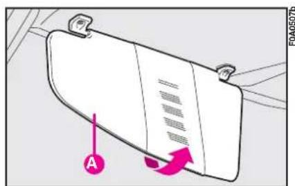
text_image
A FOA0507bfig. 101

Never travel with the shelf tilted. The shelf or the objects on it can injuries in the event of a
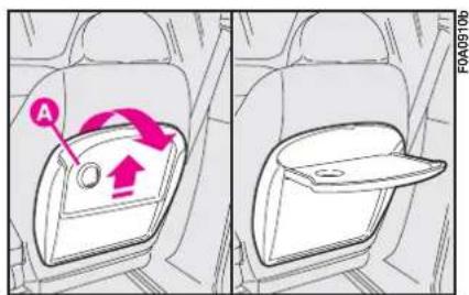
text_image
A FOA0910bfig. 101a
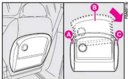
text_image
Diagram showing car interior compartments with labeled parts A, B, and C, including a dashed arrow indicating direction of movement.fig. 101b
SIDE SLIDING WINDOW (longitudinal sliding)
The windows slide open.
I) Keep pressed button A-fig. 102 to release the sliding window.
2) Push the window in the direction of the arrow (1), to open as required.
3) To close, pull the sliding window in the direction of the arrow (2) until you hear it click.
REAR SIDE WINDOWS
The windows open outwards.
1) Move the lever as shown in fig. 103.
2) Push the lever outwards to open the window completely.
3) Push the lever back until it clicks.
To close the windows, pull the lever the opposite direction until it clicks.
WING WINDOW
IMPORTANT Open and close the wing window only when the vehicle is stationary.
The Fiat Doblò may fit a handy wing window on the roof on the back of the load compartment to carry long objects.
Opening the wing window
To open the wing window, pull lever A-fig. 104 downwards in the direction of the arrow.
Put your hand in handle B-fig. 105 and lead the wing window while it opens.
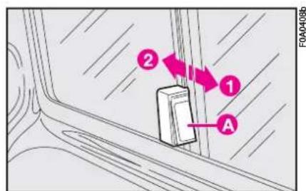
text_image
① ② A FOA0408bfig. 102
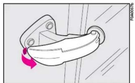
natural_image
Diagram of a mechanical component with a blue arrow indicating rotation (no text or symbols)fig. 103
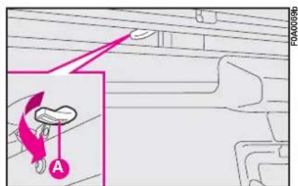
text_image
FOA00099b Afig. 104

Do not exceed 110 km/h speed with wing window open. Risk of (violent)
wing window closing.
The mobile crossmember C-fig. 106 can be tipped down to facilitate loading and unloading long objects.
To tip, hold the crossmember with your left-hand and move the lever D with your right-hand in the direction of the arrow until it clicks.
Lower the crossmember carefully until it reaches its position. Unload the vehicle and take the crossmember back to its original position.
Closing the wing window
Take the mobile crossmember C- fig. 106 back to its original position; fit the crossmember pin C in the original housing until it clicks.
Pull the wing window in the direction shown in fig. 105, fitting your hand in handle B. The wing window is closed once it clicks.
IMPORTANT Arrange the load evenly along the crossmember and fasten it with ropes or similar.
IMPORTANT Never leave the crossmember unfastened while the vehicle is moving.

Moving the vehicle when the crossmember is not fastened in its housing can
cause severe damage to the load compartment structure. Furthermore, only the bottom of the rear doors would be locked and this could damage the hinges.
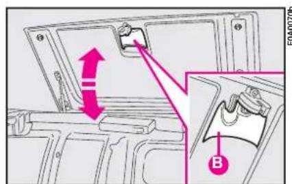
text_image
Technical diagram showing a door handle assembly with labeled parts and directional arrows, including a magnified inset of the component B.fig. 105
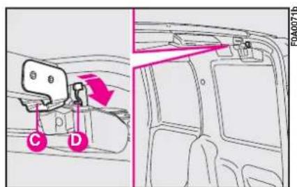
text_image
Diagram showing car interior components with labeled parts C and D, including directional arrows and a red arrow indicating flow or movement.fig. 106
DOORS
FRONT DOORS
Opening by hand from the outside
Front doors: turn the key to 2-fig. 107 and pull the handle.
Locking by hand from the outside
Front doors: close the door and turn the key to 1-fig. 107.
Opening by hand from the inside
Front doors: pull the lever.
Closing by hand from the inside
Front doors: close the door and press the lever as shown in fig. 108 (LOCK).
ELECTRIC WINDOWS
According to versions, power window controls can be set on the dashboard (in central position) fig. 109, or on driver and passenger door panels fig. 109a. They only work with ignition key at MAR.
A - to open/close the front left-hand window;
B - to open/close the front right-hand window.
These operations are allowed for two minutes after turning the ignition key from MAR to STOP or removed only if the doors are closed.
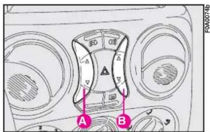
text_image
A B F0A0074bfig. 109
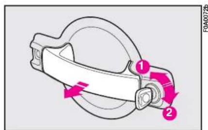
text_image
1 2 FOA0072bfig. 107
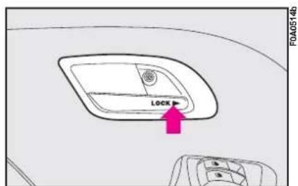
text_image
F0A0514b LOCKfig. 108
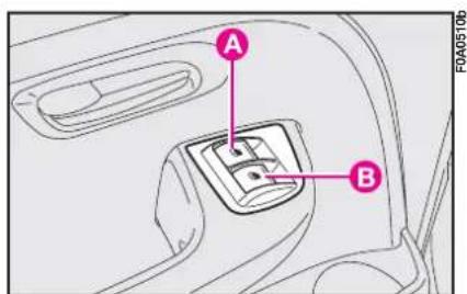
text_image
A B F0A0510bfig. 109a
On driver's side there is a button A-fig. 109 for automatic operation. Press the button for longer than one second: the window will stop when it reaches the end of its travel (or until the button is pressed again).
SIDE DOORS In Doblò Cargo versions, the side

Check that it is safe to open a door before doing so.
sliding door is fitted with a catch which stops it when it is fully open: to release the catch, simply push the door against the catch and pull it forwards forcefully.
In any case, always make sure that the door is correctly fastened in the door open catch.
Improper use of the electric windows can be dangerous. Before and during their operation ensure that any passengers are not at risk from the moving glass either by personal objects getting caught in the mechanism or by being injured by it directly. Always remove the ignition key when you get out of the vehicle to prevent the electric windows being operated accidentally and constituting a danger to the people left in the vehicle.

Make sure that the left-hand sliding side door is completely closed before using (see "At the filling station this chapter). You could use the door and the sliding system which comes into when the fuel flap is open.

Do not leave the vehicle parked on a steep slope with the sliding door. An involuntary knock could be the door and make it

You cannot open the left-hand sliding side door while refuelling when the open (see "At the filling" in this chapter).

When leaving the vehicle parked with the sliding doors open, always check the door hooks are properly d into the retaining device are it remains fully open.
Opening/closing from the outside (Fiat Doblò Cargo versions)
Opening: turn the key to 2-fig. 110 and pull the handle in the direction of the arrow then, make the door slide backward to the stop limit catch.
Closing: use the external handle and push the door forward. Turn the key to 1- fig. 110.
Opening/closing from the inside (Fiat Doblò Cargo versions)
Opening: pull the opening lever fig. III and make the door slide backward to the stop limit catch.
Closing: close the door making it sliding forward, then press once the lever at "LOCK" as shown in fig. III.
Opening/closing from the outside (Fiat Doblò Passenger Transport/Combi versions)
Opening: pull the handle as shown by the arrow fig. 110 and make the door slide backward.
Closing: pull the handle as shown by the arrow fig. 110, thus releasing the lock and make the door slide forward.
Opening/closing from the inside (Fiat Doblò Passenger Transport/Combi versions)
Opening: pull the release lever A-fig. 112 and make the door slide backward.
Closing: pull the release lever A and make the door slide forward; lock the door by pressing the handle button B.
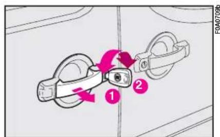
text_image
1 2 FOA0709bfig. 110
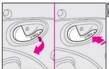
text_image
LCCX-1 LCCX-2 FOA00736fig. III
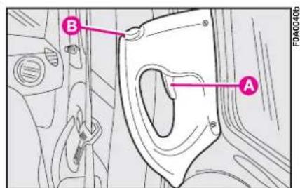
text_image
B A FOA00406fig. 112
CHILD LOCK
To prevent opening the sliding side doors from the inside.
Engage by inserting the tip of the ignition key as shown in fig. 113 and turning it.
Position I - device off.
Position 2 - device on.
The device will be engaged even if the doors are unlocked electrically.

When children are present in the vehicle this device should always be
used.
REAR DOUBLE DOORS
The double rear doors are fitted with a catch which stops the opening at an angle of approximately 90^ .

The catch system is designed to ensure the best comfort in use. An acci-knock or gust of wind lease the doors and make lose.

When open to 180°, the doors are not blocked. Do not use this system when a hole is parts on a slope or t is windy.
Opening the first door from the outside I-fig. 114
Turn the key to position 2-fig. 115 and pull the door handle in the direction of the arrow.
Closing the first door from the outside 1-fig. 114
Turn the key to position I-fig. 115.
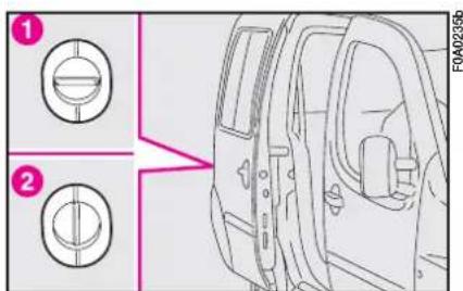
text_image
Diagram showing two circular components with numbered labels and a magnified view of the door panel, likely illustrating a mechanical or electrical assembly.fig. 113
It is possible to increase the opening angle of the two doors to facilitate loading and unloading operations. Force the doors open. This will allow opening the doors by approximately 180°.
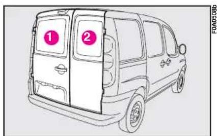
text_image
① ② FOA05086fig. 114

Close the right-hand door 2-fig. 114 completely first and then close the left-hand door 1-fig. 114. Never close both doors at the same time.
Opening the first door from the inside I-fig. 114
Lift lever A-fig. 116 in the direction of the arrow.
Opening the second door 2-fig. 114
After opening the first door, pull handle A-fig. 117 in the direction of the arrow.
IMPORTANT Only use the handle A-fig. 117 in the direction shown in the figure.
The swing doors (where provided) are fitted with a device A-fig.117a that limits their opening.
Take care not to move the rod from its housing; if it is moved by accident ①fig. 117b, restore it to the correct position ②fig. 117b.
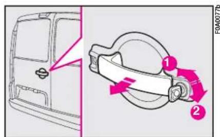
text_image
FOA0077b 1 2fig. 115
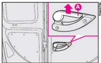
text_image
A F0A0078bfig. 116
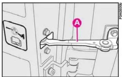
text_image
A FOA0800bfig. 117a

text_image
FA0400796 Afig. 117
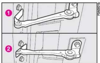
natural_image
Technical line drawing of a mechanical lever assembly (no text or symbols)fig. 117b
TAILGATE
Opening/closing the tailgate
To open the tailgate from the outside, turn the ignition key in lock fig. 118 and pull handle A in the direction of the arrow.
The opening of the boot is made easier by the gas-filed struts on each side.
IMPORTANT Fit the key well into the lock before turning it.
You will be able to open the tailgate with the key only if you remove the key from the lock after turning it by 45 degrees.
To close, lower the tailgate until the lock clicks.
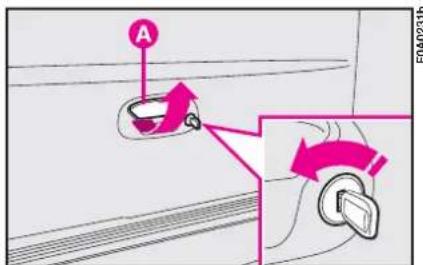
text_image
A F0A0231bfig. 118
If you are travelling in areas where refuelling can be difficult and you want to carry a can of petrol, follow the law in force. Use a homologated can and secure it adequately. Even given these precautions, the risk of fire in the event of an accident is increased.
When using the boot, make sure the load you are carrying does not exceed the permitted weight (see "Technical specifications"). Also ensure the items in the boot are arranged properly to prevent them being thrown forwards and injuring passengers should you brake sharply. Do not travel with the tailgate open: exhaust gas could filter into the passenger compartment.
IMPORTANT Adjust the height of the dipped headlight beam when travelling at night with a rather heavy load in the boot (see "Headlights" in this chapter).
Make sure the load does not exceed the values shown in "Weights" paragraph, "Technical specifications" chapter for correct operation of the headlight adjustment device.

Do not knock the tailgate into objects on the roof rack when you open it.

Do not use the key as a handle to open the tailgate. You could damage it.
CENTRAL DOOR LOCKING SYSTEM
From the outside
With the doors closed, fit and turn the key in one of the front door locks.
From the inside
With the doors closed, press (to lock) or lift (to unlock) one of the side door knobs (Fiat Doblò Passengers Transport versions). Alternatively, either press "LOCK" (to lock) or pull (to unlock) the front and side door handles (Fiat Doblò Cargo versions).
The side door knobs will lock or un-lock only the specific door.
IMPORTANT If one of the doors is not shut properly or there is a failure in the system, the central locking (where provided) feature will cut out and after some attempts the device stops working for about two minutes. In these two minutes, the doors can be locked or unlocked manually without the electrical system coming into play. After the two minutes, the control unit is ready to receive commands once more.
If the cause of the failure is removed, the device will start working properly, otherwise it will cut out once more.
BOOT
EXTENDING THE BOOT
Split seat
Before setting off, make sure that the seats in the direction of travel and perfectly fastened to the anchoring. Only in this position can be seat belts be used correctly.
The boot can be extended completely or partially.
Tipping the entire seat
The seat back and cushion release devices are in the points shown in fig. 119.
Lift knobs A-fig. 119 and tip the seat back forwards.
To tip the entire seat, lift the cushion with lever B-fig. 120.
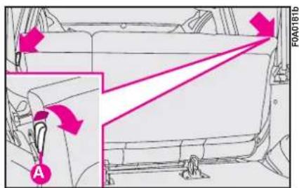
text_image
F0A0181b Afig. 119
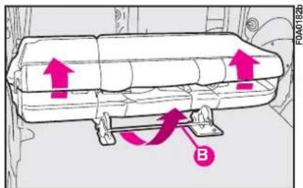
text_image
F0A0182b Bfig. 120
Tipping part of the left seat
To tip the left-hand side of the seat back:
- remove the head restraint (if provided);
- lift knob A-fig. 121 then tip the entire seat fig. 122.
Refit head restraints back into the seats A-fig. 123.
To remove the rear window shelf
The shelf is split into to parts fig. 124. Proceed as follows to remove the entire shelf:
I) Open the rear doors or the tail-gate.
2) Lift part A-fig. 124 of the shelf and place it on part B.
3) Fasten the two parts by means of rubber fasteners C-fig. 125.
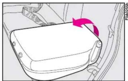
natural_image
Diagram of a car seatbelt with a pink arrow indicating rotation (no text or symbols)fig. 122
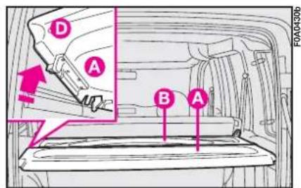
text_image
D A B A FOA04306fig. 124
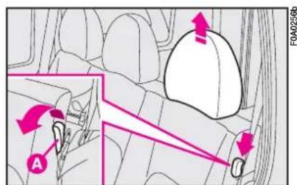
text_image
FOA0256b Afig. 121
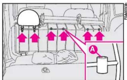
text_image
FA0400936 Afig. 123
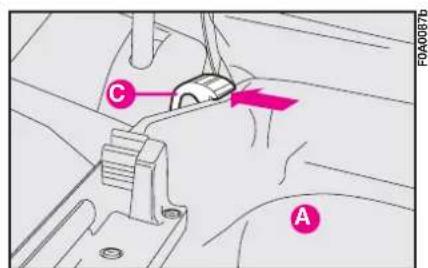
text_image
C Afig. 125
4) Lift part B-fig. 126 making the shelf slide along the available space behind the seat so that the upper part is fastened to the rear window shelf and the lower central part to the seat.
If the seat is down, proceed as follows:
5) Remove the shelf and arrange it crosswise between the front seat backs and the tipped seat on the rear seat.
To refit the shelf, refit central catches D-fig. 124 and tip first part B and then part A, make sure shelves are properly secured.
IMPORTANT Check and adjust the height of the dipped headlight beam when travelling at night with a rather heavy load in the boot (see "Headlights" in this section).
To take the seat back to normal position:
I) Check that the seat belt webbing is correctly fitted in its bracket.
2) Take the cushion to its horizontal position and check that it is correctly fastened.
3) Tip the seat back backwards and check that it is correctly fastened.
7-seat versions
To extend the boot, proceed as follows:
- remove head restraints;
- release the right locking lever B-fig. 127 moving it to I ("released lever"); do the same on the left side then lower the seat back and tip the seat forward. This operation is made friendly by two springs. Make sure the seat is completely tipped.
- refit head restraints back into the seats C-fig. 128.
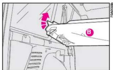
text_image
FOA0088b Bfig. 126
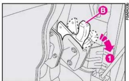
text_image
B 1 F0A0433bfig. 127

It is absolutely forbidden to use the third row seat for transporting loads when the seat back is tilted. Load could be projected forward against the seat back of the second row seats thus causing injuries to passengers fig. 127a.
To re-position the seat:
- seat back anchoring levers, both right and left B-fig. 127 must be at I (released); otherwise move both levers to position I;
- raise first the seat back (without securing it) then secure the entire seat to the floor anchorings and then secure the seat back.

Always check that seats are anchored to the floor before securing the seat
backs.
To remove the seat in order to increase the boot space, tilt the seat and remove the tool bag (keep it on the vehicle) then use lever D-fig. 128 to release catches.
Reverse the above operations for refitting.
To increase the boot space you can also tilt the second rear row as follows:
- tilt side seats (as described in paragraph "access to the third row rear seats");
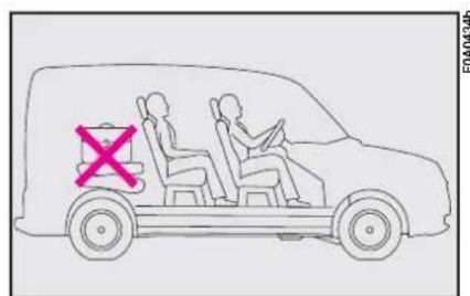
text_image
Diagram showing a van with two people, one marked with a red 'X' symbol, indicating a violation or restriction.fig. 127a
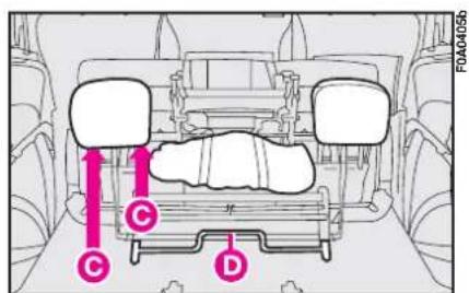
text_image
C D FAA0405bfig. 128
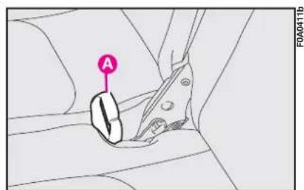
text_image
A FOA0411bfig. 129
- tilt the central seat back pulling band A-fig. 129 upwards;
— pull the bands B-fig. 130 and tilt the seat completely; - secure tilted seats by the proper belts C-fig. 131 (one per seat) to the front headrests.
IMPORTANT Do not travel with second row seats tipped and third row seats set in normal position of use, a buzzer will sound to indicate the wrong seat position.
To re-position the seats, release the belts C-fig. 131, tilt the side seats and the central seat cushion then pull band A-fig. 129 to tilt the seat back and anchor it to the proper brackets.
It is absolutely forbidden to travel with the second row seats tipped and passengers seated on the third row seats (as specified on the seat label).
ANCHORING THE LOAD
A boot mat is provided (optional for Fiat Doblò Cargo base versions). To fasten the load, fastening hooks are provided (quantity varying according to versions) fig. 132 secured to the floor and that can be accessed directly also if the mat is fitted.
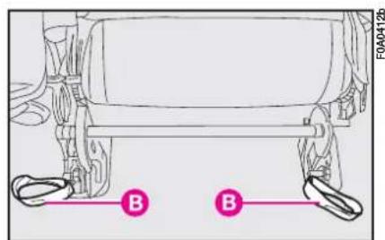
text_image
B B F0A0412bfig. 130
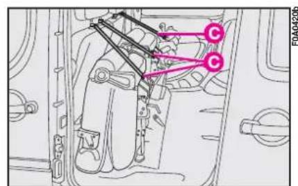
text_image
C C FOA04206fig. 131
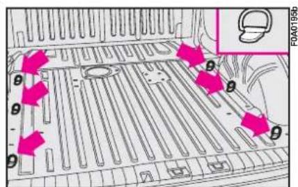
text_image
θ θ θ θ θ FOA01956fig. 132
BONNET
To open the bonnet

This should only be done when the vehicle is stationary. Before opening the bonnet, check the windscreen wiper arms are not lifted from the windscreen.
I) Pull the yellow lever A-fig. 133 in the direction of the arrow.
2) Raise the bonnet slightly until locating the release lever.
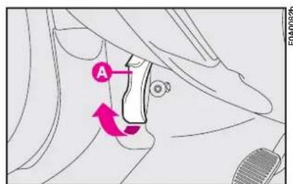
text_image
A FOA00826fig. 133
3) Press the fastener A-fig. 134, as shown in the figure.
4) Open the bonnet and release the rod A-fig. 135 from its clip at the same time. Then B on the bonnet.

Important. The bonnet might fall violently if the support rod is not posi-properly.
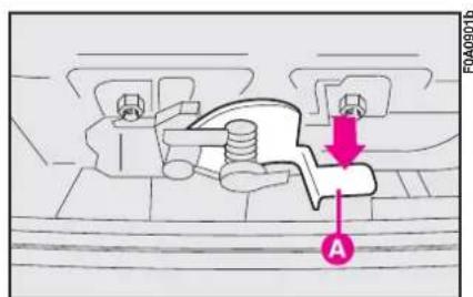
text_image
FA0409016 Afig. 134

When the engine is hot, mind your hands when working inside the engine compartment to avoid burning yourself. Never put your hands near the fan: it could start up even without the key in the switch. Wait until the engine cools down.

Take care that scarves, ties or loose clothing do not accidentally come near moving parts; they could become entangled with serious danger for the wearer.
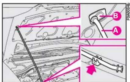
text_image
A B FOA0084bfig. 135
To close the bonnet
I) Hold the bonnet up with one hand and, with the other, remove rod A-fig. 135 from recess B and replace it in its clip.
2) Lower the bonnet until it is about 20 cm above the engine compartment, and then let it drop, ensuring that it is fully closed and not just held in position by the safety catch.
If the bonnet does not close properly do not push it down but open it again and repeat the above procedure.
ROOF RACK/SKI RACK
PRESETTING
To use the roof racks you shall remove the caps set in points fig. 136.
Attach the roof rack bar brackets to the fasteners.
IMPORTANT Always follow the instructions provided with the kit carefully. The bars should be fitted by skilled personnel.

After travelling a few kilometres, check that the attachment fastening are tight.

Distribute the load evenly and when driving, bear in mind the increased vity of the vehicle to side

For safety reasons the bonnet must be closed properly to avoid its
opening while the vehicle is travelling. Therefore, always check it is properly closed and the catch engaged. Should you notice that the catch is not perfectly engaged when travelling, stop the vehicle immediately and close the bonnet.
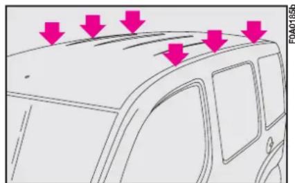
natural_image
Diagram of a car's front bumper with red arrows pointing to the rim (no text or symbols present)fig. 136

Never exceed the max. permissible loads (see section "Technical speci-ns").

Strictly comply with current law regulations concerning max. overall di- ons.
LOADING RAMPS
Loading ramps are available at Lineaccessori Fiat.
To use the rear ramp fig. 137, strictly follow the instructions shown on the plate applied on the left side of the boot.
IMPORTANT Max. rear ramp car-rying capacity is 250 kg.

Loading with ramps shall be only carried out with the vehicle station-d handbrake engaged.

Never move the vehicle with ramps extracted. Before restarting the ve-
hicle always check that ramps are properly secured into their housings.
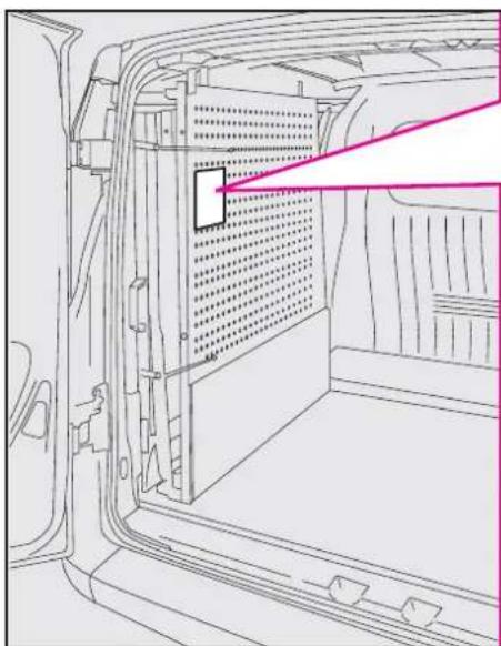
natural_image
Line drawing of a vehicle door frame with ventilation grilles and a highlighted panel (no text or symbols)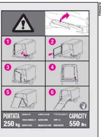
text_image
PORTATA CAPACITY CAPACITY 250 kg TRAF/AMOUNT BANANA CHAPACITY CAPACITY CAPACITY 550 lbsfig. 137
To use the side ramp, fig. 138, open the side sliding door, take handle A and take out the ramp as shown by the arrow until locking it.
IMPORTANT Max. side ramp car-rying capacity is 60 kg.
When you have finished, take handle A and refit the side ramp into its housing making it sliding as shown by the arrow fig. 138.
HEADLIGHTS
ADJUSTING THE HEADLIGHT BEAM
The correct positioning of the head-light beams is very important for the comfort and safety, not only of the person driving the vehicle but also all other road users.
This is also covered by a specific law.
To ensure you and other drivers have the best visibility conditions when travelling with the headlights on, the headlights must be set properly.
Have the headlight positioning checked at a Fiat Dealership and adjusted if necessary.
SLANT COMPENSATION
The vehicle is fitted with an electrical device for correcting the headlight slant. The device can be operated with ignition key at MAR and dipped beams on.
When the vehicle is loaded, it "slopes" backwards. This means that the headlight beam rises. In this case, it is necessary to return it to the correct position.
Proceed as follows:
- hold button B-fig. 139 pressed to increase by one position (e.g.: 0→1, 1→2, 2→3);
- hold button A pressed to decrease by one position (e.g.: 3→2, 2→1, 1→0).
Display C shows the positions during the adjustment.
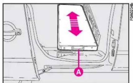
text_image
FA0A0234b Afig. 138
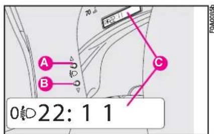
text_image
A B C 0:22: 1 1fig. 139
Correct positions as a function of the load
0 - one or two occupants in the front seats.
I - five occupants.
2 - five occupants + load in boot.
3 - driver + maximum permissible load stowed in boot.

Check the headlight beam position every time you change the load to be
carried.
HEADLIGHT ADJUSTMENT ABROAD
Headlights are orientated as to drive inside the country of origin before selling the vehicle. When travelling in countries with opposite driving direction, you need to cover the headlight areas according to the Road Code of the country you are travelling in.
ABS
The vehicle can be fitted with an ABS braking system, which prevents the wheels from locking when braking, makes the most of road grip and gives the best control when emergency braking under difficult road conditions.
The driver can tell the ABS system has come into play because the brake pedal pulsates slightly and the system gets noisier.
This should not be interpreted as a fault in the brakes; on the contrary it is a sign that the ABS system is working: it tells the driver that the vehicle is travelling at the limit of its road grip and that he should alter his speed to fit the type of road surface.
The ABS system is an addition to the basic braking system. If there is a malfunction, the system turns off automatically and only the ordinary brakes continue to work.
If a failure occurs, and consequently the anti-lock function is not effective, the braking system will continue to work as usual.
If you have never driven a vehicle with ABS before, you should practice using the system on slippery terrain, obviously with the necessary safety precautions and keeping to the Highway Code of the country you are in. It is also a good idea to read the following information carefully.
The advantage in using the ABS system is that it continues to give you maximum manoeuvrability even when braking hard in conditions of poor grip by preventing the wheels locking.
You should, however, not expect the braking distance to always decrease: for example surfaces with gravel or fresh snow on a slippery road will in fact increase the braking distance.
To exploit the ABS system to the full in the event of necessity, you should take heed of the following advice:
If there is a fault, the instrument panel warning light will come on. At this point, reduce speed and go to a Fiat Dealership to have your vehicle checked and put right immediately.
The ABS exploits the road hold available as much as possible but cannot increase it. You should always drive carefully on slippery surfaces and avoid any unnecessary risks.
Braking while cornering always requires extreme care even when using ABS.
The most important advice to follow is this
If the ABS system cuts in it is a sign that the grip between the tyre and the road surface has reached the limit: you must slow down to match the speed to the road grip available.
When the ABS cuts in, and you feel the brake pedal pulsating, do not remove your foot, but keep it pressed. In doing so you will stop in the shortest amount of space possible under the current road conditions.
If you follow these tips you will be able to brake better in any situation.
IMPORTANT Vehicles fitted with may only be fitted with wheel rims, tyres and brake pads of the make and model approved by the vehicle manufacturer.
The system is completed with an EBD electronic brake force distributor which increases the brake system performance and employs the ABS control unit and sensors.
The vehicle is fitted with an electronic braking device (EBD). The Ⓗ and Ⓔ warning light will come on at the same time when the engine is running to indicate that there is an EBD system failure. In this case violent braking may be accompanied by early rear wheel locking with the possibility of skidding. Drive the vehicle extremely carefully to the nearest Fiat Dealership to have the system checked.

Warning light (ANS) alone, with the engine running, normally indicates a fault in the ABS system only. In this case, the braking system is still efficient, though without the anti-locking device. Under these conditions, performance of the EBD system may be reduced. Also in this case, you are advised to go immediately to the nearest Fiat Dealership, driving in such a way to avoid sharp braking to have the system checked.

If the Ⓔ brake fluid low warning light comes on, stop the vehicle immediately and contact the nearest Fiat Dealership. Fluid leaks from the hydraulic system, in fact, can compromise brake system operation, both traditional systems and systems with ABS.
FRONT AND SIDE AIRBAGS
The vehicle can be fitted with front air bags for the driver and passenger and with side bags.
FRONT AIRBAGS
Front airbags (driver and passenger) have been designed to protect the occupants in the event of head-on crashes of medium-high severity, by placing the cushion between the occupant and the steering wheel or dashboard.
Front airbags are designed to protect vehicle's occupants in front crashes and therefore non-activation in other types of collisions (side collisions, rear shunts, roll-overs, etc.) is not a system malfunction.
In case of crash, an electronic control unit, when required, triggers the inflation of the cushion according to the severity of the collision.
The cushion immediately inflates, placing itself as a protection between the body of the front occupants and the structure that could cause injuries. Immediately after, the cushion deflates.
The front air bag (driver and passenger) is not a replacement of but complementary to the use of belts, which should always be worn, as specified by law in Europe and most non-European countries.
In case of crash, a person not wearing the seat belt moves forward and may come into contact with the cushion while it is still inflating. Under this circumstance the protection offered by the airbag is reduced.
Front airbags may not activate in the following situations:
- in collisions against highly deformable objects not affecting the vehicle front surface (e.g. bumper collision against guard rail);
- in case of wedging under other vehicles or protective barriers (for example under a truck or guard rail), the air bag is not triggered as it offers no additional protection compared with the seat belts, consequently it would be pointless.
Therefore, failure to come into action in the above circumstance does not mean that the system is not working properly.
At their maximum inflation, their volume fills most of the space between the steering wheel and the driver and between the dashboard and the passenger.
In minor crashes (for which the restraining action of the seat belts is sufficient), the air bags are not deployed. Also in this case it is of vital importance to wear the seat belts since in case of front crash they guarantee proper positioning of the occupant.
DRIVER'S FRONT AIR BAG fig. 140
It consists of an instant-inflating cushion contained in a special recess in the centre of the steering wheel.
PASSENGER'S FRONT AIR BAG fig. 141
It consists of an instant-inflating cushion contained in a special recess in the dashboard; its volume is bigger than the driver's one.

Do not apply stickers or other objects to the steering wheel or to the
air bag cover on the passenger's side or on the side roof lining. Never put objects on the dashboard on passenger side since they could interfere with proper air bag inflation.
The driver and passenger front airbags have been designed and calibrated to protect a person wearing seat belts.
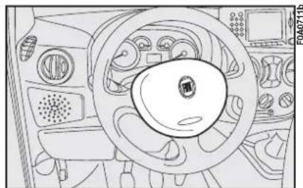
natural_image
Interior view of a vehicle dashboard with steering wheel and control panels (no visible text or symbols)fig. 140
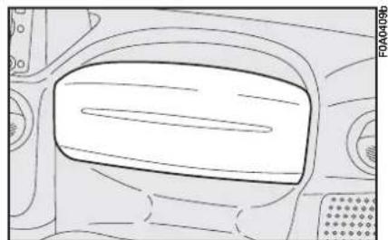
natural_image
Line drawing of a car interior showing the dashboard and seat area (no text or symbols)fig. |4|


SERIOUS DANGER: With passenger's air bag active (ON), never place child's seats with the cradle facing backwards since the air bag activation could cause to the child serious injuries, even mortal. In the case of need, always deactivate the passenger's air bag when a child's seat is placed on the front seat. The front passenger's seat shall be adjusted in the most backward position to prevent any contact between child's seat and dashboard. Even if not compulsory by law, you are recommended to reactivate the air bag immediately as soon as child transport is no longer necessary.
Manual deactivation
The passenger side airbag can be deactivated if it is absolutely necessary to carry a child in the front passenger seat.
Deactivation / reactivation shall be carried out with ignition device at STOP. Turn the specific switch fig. 142 on the dashboard on passenger side with the ignition key.
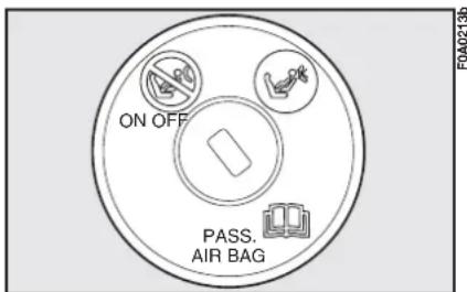
text_image
ON OFF PASS. AIR BAGfig. 142
IMPORTANT Operate the switch only with engine off and ignition key removed.
The switch fig. 142 has two positions:
- Passenger front airbag on: (position ON Ⓧ ): instrument panel warning light √ off. Do not carry children on the front seat.
- Passenger front airbag off: (position OFF ☐): instrument panel warning light ☐ on. A child can be carried on the front seat with a suitable restraint system.
Warning light 📁 on the cluster stays on permanently until the passenger's airbag is reactivated.
Deactivation of the passenger's front air bag does not inhibit operation of the side air bag.
SIDE BAG
It consists of an instant-inflation cushion housed in the back rest of the front seat to increase protection of the occupants' chest in the event of a side crash of medium-high severity.
GENERAL INFORMATION
The front and/or side airbags can be triggered if the vehicle is subjected to strong knocks or impacts underneath, e.g. violent crashes into steps, kerbs or fixed projections from the ground, falling to large holes or dips in the road.
When the airbag inflates it emits a small amount of dusts. These dusts are harmless and is not the beginning of a fire; then the unfold cushion surface and the vehicle interiors can be covered by a dusty remains: this dust can irritate skin and eyes. In case of contact, wash yourself using neutral soap and water.
The air bag system has a validity of 14 years as to the pyrotechnic charge, and 10 years as to the coil contact (see the plate in the glove compartment). As this date approaches, contact Fiat Dealership to have it replaced.
After an accident which triggered the airbags, go to a Fiat Dealership to have the entire safety system, the electronic control unit, the seat belts and the pretensioners replaced. The Dealership will also check the intactness of the electrical system.
Any diagnostic, repair or replacement operations concerning the airbag system must exclusively be carried out at a Fiat Dealership.
If you are having the vehicle scrapped, have the airbag system deactivated at a Fiat Dealership first.
If the vehicle changes hand, the new owner must be made aware of the indications given above and be given this Owner Handbook.
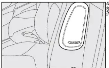
natural_image
Diagram of a car interior with a highlighted oval area, showing no text or symbols.fig. 143
Pretensioners, front airbags and side airbags are triggered by the electronic control unit according to different types of impacts. Missed triggering of the system, consequently, does not indicate a fault in the system.
When the passenger's front airbag is active (passenger front airbag deactivation switch at ON), the √ warning light will come on for approximately four seconds and flash for other four seconds when the ignition key is turned to MAR to remind the driver than the passenger's front and side airbags (where fitted) will be fired in the event of a crash. The warning light should go out immediately afterwards.
The front air bag is triggered for shocks greater in magnitude that the pretensioners. For impacts between these two thresholds, it is therefore normal that only the pretensioners are triggered.
If when turning the key to MAR the warning light does not turn on or if it stays on when travelling there could be a failure in safety systems; in this event air bags or pretensioners could not trigger in case of impact or, in a minor number of cases, they could trigger accidentally. Contact Fiat Dealership immediately to have the system checked.
If an attempt has been made to steal the vehicle, or if it has actually been stolen or has been vandalised in any way or subjected to flooding, have the airbag system checked over at a Fiat Dealership.
Do not apply stickers or other objects to the steering wheel or to the dashboard on the passenger's side. Do not travel with objects on your lap or in front of you nor with a pipe, pencil or similar between your lips; you could seriously hurt yourself if the airbag inflates in a collision.

Always drive with both hands on the rim of the steering wheel so that the airbag is free to inflate during a head-on collision, and protect you from serious injury. Do not drive with your body bending towards the steering wheel, but sit in an upright position with your back resting against the seat.

It is important to remember that the airbag can be fired if the ignition key is fitted and at MAR also if the engine is not running and the vehicle it is hit by another vehicle travelling at suitable speed. As a consequence, Fiat recommends sitting children in their specific restraint systems on the back seat, which is the most protected position possible. On the contrary, the airbags will not be fired if the vehicle is crashed into when the key is not inserted or turned. Consequently, in this case, the fact that the system is not fired does not indicate a fault.

The correct operation of front airbags, side airbags and pretensioners is ensured only if the vehicle is not overloaded.

Do not wash the seat back in vehicles with side airbags with pressurised steam or water in automatic seat washing stations.

Do not cover the back-rest of front seats with trims or covers that are table to be used with side

The airbag does not replace seat belts but rather increases their effectiveness. Furthermore, the airbag is not fired in the event of low speed front collisions, side collisions, rear-end shunts and rollovers. In these cases, the passengers are only protected by the seat belts which for this reason must always be fastened.
EOBD SYSTEM
The EOBD system (European On Board Diagnosis) allows continuos diagnosis of the components of the vehicle correlated with emissions.
Furthermore, the system warns the driver of deterioration concerning the emission system components by means of the warning light on the instrument panel.
The objective is to:
– monitor system efficiency;
- warn when failures can increase emissions over the threshold established by the European regulations;
– warn of the need to replace deteriorated components.
Furthermore, the system is equipped with a connector for interfacing with specific tools used to read the error codes stored in the control unit memory along with a set of diagnostic and engine specific parameters.

Contact a Fiat Dealership as soon as possible if the warning light either does not come on when the key is turned to MAR or comes on, with fixed or flashing light, when travelling. Warning light operation can be checked by means of special equipment by traffic agents. Always comply with the traffic regulations in force in the country where you are travelling.
IMPORTANT After eliminating the problem, your Fiat Dealership will run a bench test to fully check the system. In some cases, a long road test may be required.
SOUND SYSTEM
If the “Sound System” has not been requested, the vehicle features an odd-ment compartment on the dashboard.

Contact a Fiat Dealership if you want to install a sound system after purchasing your vehicle. Their staff will advise you on how to safeguard the life of the battery. Excessive idle intake can damage the battery and invalid the battery warranty as well.
LIGHT PRESETTING
The system consists of the following:
– sound system power wires;
- wires for front speakers on the dashboard, doors (where provided) and rear speakers for passengers transport versions;
– sound system compartment;
- aerial wire and aerial.
HEAVY PRESETTING
The system consists of the following:
– sound system power wires;
- wires for front speakers on the dashboard;
- 2 speakers on the dashboard;
- wires for door speakers (where provided);
- 2 door speakers;
- 2 rear speakers (for passengers transport versions);
- wires for rear speakers;
– sound system compartment;
- aerial wire and aerial.
Speakers
- two mid-range speakers on dashboard, diameter 100 mm, power 30W max each.
- two woofer speakers on front doors, diameter 165 mm, power 40W max each (Panorama versions only).
- two full-range elliptic speakers on rear window shelf, 95 x 154 mm, power 20W max each (Panorama versions only).
Sound system installation
To fit the sound system, remove the oddment compartment shown in fig. 145. To remove the compartment, press it upwards and then pull it out towards the inside of the vehicle.
CELLULAR PHONE SET-UP
The system set-up consists of:
- a dual-purpose aerial (sound system + cellular phone), on the vehicle roof;
- a dual-purpose aerial connection wires and ten-pin connector wiring fig. 146.
- a double coil speaker (sound system + cellular telephone), located on the passenger side dashboard.
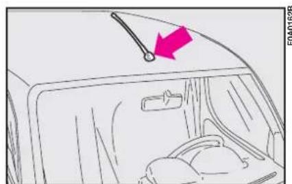
natural_image
Interior view of a car showing the dashboard and seat area with a pink arrow pointing to the dashboard (no text or symbols present)fig. 144
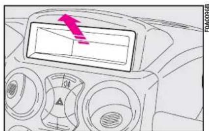
text_image
Diagram of a car dashboard with directional arrow and control panel, showing temperature reading and warning symbolfig. 145
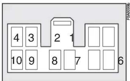
text_image
4 3 2 1 10 9 8 7 6 F0A0099bfig. 146

Maximum power to be applied to the aerial is 20W.
Wiring diagram:
I Sound system mute function.
2 Spare.
3 Cellular phone input earth signal.
4 Cellular phone INPUT signal.
5 Dual-purpose speaker on the front passenger side door (+).
6 Dual-purpose speaker on the front passenger side door (-).
7 Ignition switch power (+15).
8 Spare.
9 Battery power (+).
10 Earth.
Have the cellular telephone and the connections performed by a Fiat Dealership only.
In Fiat Doblò passengers Transport versions, use a screwdriver in the point shown in fig. 147 to reach the ten pin connector. Lift the central tunnel cover and remove the connector.
In Fiat Doblò Cargo versions, loosen the screws shown in fig. 148 in the glove compartment to reach the ten pin connector. Use a screwdriver in the pre-cut point and remove the connector.

Purchase a free-hands kit which is compatible for your cellular telephone.

Have the cellular telephone installed and connected to the setup sys-
tem in the vehicle by a Fiat Dealership only. This will ensure the best results and prevent any problems which could effect vehicle safety.

text_image
F0A02106fig. 147
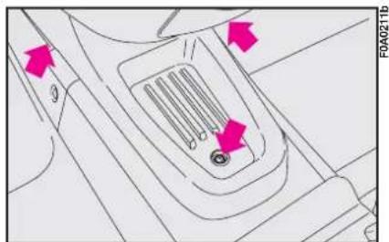
natural_image
Technical diagram of a mechanical component with arrows indicating features (no readable text or symbols)fig. 148
ACCESSORIES PURCHASED BY THE OWNER
If after buying the car, you decide to install electrical accessories that require a permanent electric supply (alarm, satellite antitheft system, etc.) or accessories that in any case burden the electric supply, contact Fiat Dealership, whose qualified personnel, besides suggesting the most suitable devices belonging to Lineaccessori Fiat, will also evaluate the overall electric absorption, checking whether the car's electric system is able to withstand the load required, or whether it needs to be integrated with a more powerful battery.
INSTALLATION OF ELECTRIC/ ELECTRONIC DEVICES
Electric/electronic devices installed after buying the car or in aftermarket shall bear the and marking:


Fiat Auto S.p.A. authorizes the installation of transceivers provided that installation is carried out at a specialized shop, workmanlike performed and in compliance with manufacturer's specifications.
IMPORTANT Installation of devices resulting in modifications of car characteristics may cause driving license seizing by traffic agents and also the lapse of the warranty as concerns defects due to the abovementioned modification or traceable back to it directly or indirectly.
Fiat Auto S.p.A. declines all responsibility for damages caused by the installation of non-genuine accessories or not recommended by Fiat Auto S.p.A. and installed not in compliance with the specified requirements.
RADIO TRANSMITTERS AND CELLULAR TELEPHONES
Radio transceiver equipment (e.g.: etacs mobile phones, HAM radio systems and the like) shall not be used inside the vehicle unless a separate aerial is mounted on the roof.
IMPORTANT The use of similar devices inside the passenger compartment (without separated aerial) produces radio-frequency electromagnetic fields which, amplified by the resonance effects inside the passenger compartment, may cause electrical systems equipping the vehicle to malfunction. This could compromise safety in addition to constituting a potential hazard for the passengers.
In addition, transmission and reception of these devices may be affected by the shielding effect of the vehicle body.
As concerns EC-approved mobile phones (GSM, GPRS, UMTS), strictly comply with the instructions for use provided by the mobile phone's manufacturer.
PARKING SENSORS (where provided)
Parking sensors are located in the rear bumper to detect and inform the driver (through an intermittent acoustic signal) about the presence of obstacles behind the vehicle.
ACTIVATION
Sensors will activate automatically when engaging reverse gear.
The frequency of the acoustic alarm will increase as the distance between the vehicle and the obstacle decreases.
BUZZER WARNINGS
When the reverse gear is engaged an intermittent acoustic signal is automatically activated (short beep to signal system activation).
The acoustic signal frequency:
- becomes louder as the reduction of distance between the vehicle and the obstacle decreases;
- becomes continuous when the distance between the vehicle and the obstacle is less that 30~cm and stops immediately if the distance raises;
- is constant if the distance is unvaried.
IMPORTANT In the event of a parking sensor system failure, you will hear an alarm signal when you engage reverse gear.
The sensors are shaped to fit into the bumpers and optimise scanning angles.
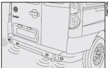
natural_image
Line drawing of a vehicle front panel with sensor waves and a battery cover (no text or symbols)fig. 149
Detection distances:
Central ray 130 cm
Corner action range 60 cm
Min/max range 25/180 cm
If several sensors signal an obstacle, the control unit checks and indicates the closest one.
The system will automatically cut out also when reverse gear is engaged after a distance of 50 or after exceeding the speed of 30 km/h.

For proper operation, the parking sensors shall always be clean from
mud, dirt, snow or ice. Therefore keep the rear bumpers clean to prevent irregular operation of the parking sensors.
AT THE FILLING STATION

Make sure that the left-hand sliding side door is completely closed before
refuelling. You could damage the door and the sliding lock system which comes into play when the fuel flap is open.

You cannot open the left-hand sliding side door while refuelling when the
flap is open.
PETROL ENGINES
Use only unleaded petrol.
To prevent errors, the diameter of the fuel tank filler is too small to introduce a lead petrol pump filler.
Use petrol with a rated octane number (R.O.N.) not lower than 95.
IMPORTANT An inefficient catalytic converter will allow harmful exhaust fumes to be emitted and thus contribute to air pollution.
IMPORTANT Never put even the tiniest amount of leaded petrol in the fuel tank of your vehicle even in an emergency. You would damage the catalytic converter beyond repair.
DIESEL ENGINES

Use diesel fuel for motor vehicles complying with European specifications
EN590 only. The use of other products or mixtures may damage the engine beyond repair and invalidate the warranty. If the tank is accidentally filled with other types of fuel, do not start the engine and drain the tank. If the engine has run even for a very short time, you will also need to drain the fuel supply circuit.
If the outside temperature is very low, the diesel thickens due to the formation of paraffin and could clog the fuel filter.
In order to avoid these problems, different types of diesel are distributed according to the season: summer type, winter type and arctic type (cold mountain areas).
If refuelling with diesel fuel not adequate, you are recommended to add TUTELA DIESEL ART to the fuel, in the proportions written on the container. Pour the antifreeze into the fuel tank before the fuel.
REFUELLING
To guarantee full tank filling, carry out two refuelling operations after the first click of the fuel delivery gun. Avoid further topping up operations that could cause damages to the fuel system.
FUEL FILLER CAP fig. 150

Make sure that the left-hand sliding side door is completely closed before
refuelling. You could damage the door and the sliding lock system which comes into play when the fuel flap is open.

You cannot open the left-hand sliding side door while refuelling when the
flap is open.
To open:
I) Turn the cap by approximately half a turn anticlockwise and remove it.
IMPORTANT The hermetic closure may cause a slight pressure in the tank: a slight hissing when turning the cap is quite normal.
2) While you are filling up, place the cap on the fuel filler flap as illustrated in the figure.
To close:
The cap has a bayonet coupling. Insert the cap and turn it clockwise until it clicks once or more.
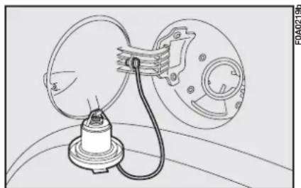
natural_image
Technical line drawing of a mechanical device with a circular component and attached housing (no text or symbols)fig. 150
On certain versions the cap has a mechanical lock to be opened using the door key.

Do not put naked flames or lighted cigarettes near the fuel filler hole as there
is a danger of fire. Do not bend too close to the hole either so as not to breathe in harmful vapours.
IMPORTANT If required, replace the fuel cap with another genuine cap to avoid affecting the efficiency of the fuel vapour recovery system.
PROTECTING THE ENVIRONMENT
Protecting the environment has been the guiding principle in the design of the Fiat Doblò right from the start. The result is the use of materials and creation of devices that can reduce or considerably curtail harmful influences on the environment.
The devices for curtailing petrol engine emissions are the following:
- a three-way catalytic converter;
– Lambda sensors (oxygen sensors); - a fuel evaporation system.
The devices for curtailing diesel engine emissions are:
– an oxidising catalytic converter;
– an exhaust gas recirculation system (E.G.R.).
– diesel particulate filter (DPF)
– Lambda probes (where provided).
Consequently, the Fiat Doblò is ready to travel well ahead of the most stringent international pollution control standards.
DIESEL PARTICULATE FILTER (DPF) (for Multijet versions 1.3 85 HP and 1.9 120 HP)
The Diesel Particulate Filter is a mechanical filter, integral with the exhaust system, that physically traps particulates present in the exhaust gases of Diesel engines.
The diesel particular filter has been adopted to eliminate almost totally particulates in compliance with current / future law regulations.
During normal use of the vehicle, the engine control unit records a set of data (e.g.: travel time, type of route, temperatures, etc.) and it will then calculate how much particulates has been trapped by the filter.
Since this filter physically traps particulates, it shall be cleaned (reclaimed) at regular intervals by burning carbon particles.
Reclaiming procedure is controlled automatically by the engine control unit according to the filter conditions and the conditions of use of the vehicle.
During reclaiming the following phenomena could take place: idling slight increase, fan activation, slight smoke increase, high exhaust temperatures. These situations shall not be considered as faults and they do not affect vehicle performance and environment.
If the dedicated message is displayed, refer to paragraph “Warning lights and messages”.
DRIVING YOUR VEHICLE
ENGINE STARTING

It is dangerous to let the engine run in a garage or other closed area. The engine consumes oxygen and gives off carbon dioxide, carbon monoxide and other poisonous fumes.

Do not touch the high voltage cables (spark plug leads) when the engine is running.
STARTING PROCEDURE FOR PETROL VERSIONS
I) Ensure that the handbrake is up.
2) Put the gear lever into neutral.
3) Press the clutch pedal fully down, without pressing the accelerator.
4) Turn the ignition key to AVV and let it go the moment the engine starts.
If the engine does not start at the first attempt, return the ignition key to STOP before trying to start the engine again.
If the warning lights CODE (7) and stay on when the ignition key is at MAR, turn the key to STOP and then to MAR again; if the warning light stays on, try with the other keys provided.
If you are still unable to start the engine, perform the emergency start-up procedure (see section "In an emergency") and go to a Fiat Dealership.
IMPORTANT Never leave the ignition key at MAR when the engine is off.
HOW TO START DIESEL VERSIONS
I) Ensure that the handbrake is up.
2) Put the gear lever into neutral.
3) Turn the ignition key to MAR. Instrument panel warning lights 📄, 00 and CODE (CODE) will come on.
4) Wait for warning lights and CODE (☐) to turn off.
5) Wait for the instrument panel warning light 00 to go out. The hotter the engine is, the quicker this will happen.
6) Press the clutch pedal down to the floor without touching the accelerator.
7) Turn the key to AVV immediately after the 00 warning light goes out. If you wait to long, you will lose the benefit of the work done by the glow plugs.

The warning light 00 will flash (for approximately 60 seconds) at start-up or during prolonged cranking to signal a fault in the glow plug heating system. You can use the vehicle as usual if the engine starts but you should contact a Fiat Dealership as soon as possible to have problem seen to.
If the engine does not start at the first attempt, return the ignition key to STOP before trying to start the engine again.
If with key at MAR warning light code (TM) stays on, turn the key to STOP and then to MAR again; if the warning light stays on, try with the other keys provided.
If you still cannot start the engine, get in touch with Fiat Dealership.
IMPORTANT Never leave the ignition key at MAR when the engine is off.
HOW TO WARM UP THE ENGINE AFTER IS HAS JUST STARTED (petrol and diesel versions)
- Begin to move forward slowly letting the engine turn at medium revs. Do not accelerate abruptly.
- Do not push the engine to its limit for the first few kilometres. You are recommended to wait until the coolant temperature gauge starts moving.
EMERGENCY START-UP
If the Fiat CODE system fails to recognise that code transmitted by the ignition key (instrument panel warning light CODE) on) the emergency start-up can be performed by using the CODE card code.
See section "In an emergency".

Catalysed vehicles must not be bump started (pushed, towed or coasted downhill) as this could cause fuel to flow into the catalytic exhaust system and damage it beyond repair.

Remember that until the engine has started the brake booster and hydraulic power steering systems will not work and a greater effort will therefore be required to depress the brake pedal or turn the steering wheel.
STOPPING THE ENGINE
Turn the key to STOP while the engine is idling.

A quick burst on the accelerator before turning off the engine serves absolutely no practical purpose and wastes fuel.
IMPORTANT After a taxing drive you should allow the engine to "catch its breath" before turning it off by letting it idle to allow the temperature in the engine compartment to fall.
PARKING
Switch off the engine, pull up the handbrake and engage a gear (1st gear or reverse, according to whether the vehicle is facing up or downhill) and leave the wheels turned. If the vehicle is left on a steep slope, wedges or a rock should be used to lock the wheels.
Do not leave the ignition key at MAR to prevent draining the battery.
Always remove the key when you leave the vehicle.

Never leave children un- supervised in the vehicle.
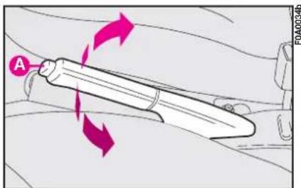
text_image
A FOA0034bfig. 1
HANDBRAKE
The handbrake lever is located between the two front seats.
Pull the handbrake lever upwards until the vehicle cannot be moved. Four or five clicks are generally enough when the vehicle is on level ground while nine or ten may be required if the vehicle is on a steep slope or laden.
IMPORTANT If this is not the case, take the vehicle to a Fiat Dealership to have the handbrake adjusted.
Instrument panel warning light Ⓑ will come on when the handbrake lever is pulled up and the ignition key is at MAR.
To release the handbrake:
I) Slightly lift the handbrake and press release button A-fig.1.
2) Keep the button pressed in and lower the lever. Warning light (!) will go out.
3) Press the brake pedal when carrying out this operation to prevent the vehicle moving accidentally.
HOW TO USE THE GEARS
Press the clutch fully before shifting the gear stick into one of the positions shown in the diagram in fig. 2 (the diagram is also on the gear lever knob).
IMPORTANT Only engage the reverse gear when the vehicle is completely stationary. With the engine running, wait for at least 2 seconds with the clutch pedal pressed to avoid damaging the gears and scratching.
To engage reverse (R) from neutral: - shift the lever to the right and back.
For version 1.4 8V and 1.6 16V, to engage reverse (R) from neutral, raise collar A-fig. 3 set under the knob and move the lever rightwards and then backwards at the same time.

You must press the clutch fully down to change gear properly. It is
therefore essential that there is nothing under the pedals. Make sure that mats are lying flat and do not get in the way of pedals.
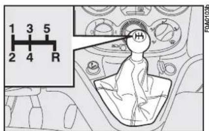
text_image
1 3 5 2 4 R H FOA01036fig. 2
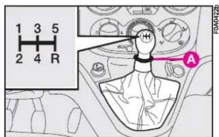
text_image
1 3 5 2 4 R A FOA0422bfig. 3
CONTAINING RUNNING COSTS AND POLLUTION
Some suggestions which may help you to keep the running costs of the vehicle down and lower the amount of toxic emissions released into the atmosphere are given below.
GENERAL CONSIDERATIONS
Vehicle maintenance
The overall state of the vehicle is an important factor which has a marked influence over fuel consumption and driving comfort and on the life span of your vehicle. For this reason care should be taken to maintain your vehicle by carrying out the necessary checks and regulations in accordance with the specifications given in the SERVICE SCHEDULE (see sections: spark plugs, idling, air cleaners, diesel fuel filter, timing).
Tyres
Tyre pressure should be checked at least once every four weeks: if the pressure is too low fuel consumption increases as the resistance to the rolling movement of the tyre is greater. In this state, tyre wear is increased and handling suffers which will effect safety.
Unnecessary loads
Do not travel with too much load in the boot. The weight of the vehicle and its trim greatly effects consumption and stability.
Roof rack/ski rack
Remove the roof rack or the ski rack from the roof as soon as they are no longer used.
These accessories reduce the aerodynamic penetration of the vehicle and will increase consumption. When transporting particularly large objects, use a trailer, where possible.
Electric devices
Use electric devices for the necessary time only. The heated rear window, fog lights, windscreen wipers, heater fan require large amounts of electricity and increasing the request for power will also increase fuel consumption (up to +25% when driving in towns).
Climate control system
The climate control system is an additional load which greatly effects the engine leading to higher consumption (up to +20% in average). When the temperature outside allows, use the air vents where possible.
Aerodynamic accessories
The use of non-certified aerodynamic items may adversely affect air drag and consumption levels.
DRIVING STYLE
Starting
Do not warm the engine when the vehicle is stationary or at high or low revs: in this way the engine will warm up gradually increasing consumption and emissions. You should drive off slowly straight away avoiding high revs so that the engine will warm up more quickly.
Unnecessary actions
Avoid revving the engine when stopped at traffic lights or before switching off the engine and avoid doubling the clutch as these actions have no purpose of modern vehicles and serve only to increase consumption and pollution.
Gear selection
As soon as the traffic and road conditions allow it, shift to a higher gear. Using a lower gear to liven up acceleration greatly increases consumption. In the same way, improper use of the higher gears will increase consumption, emissions and wear and tear on the engine.
Top speed
Fuel consumption increases considerably as speed increases. For example, when accelerating from 90 to 120 km/h, fuel consumption increases up to approximately +30%. Your speed should be kept as even as possible and superfluous braking and acceleration avoided as this increases both consumption and emissions. A “smooth” driving style should be adopted by attempting to anticipate manoeuvres to avoid imminent danger and to keep a safe distance from the vehicle in front to avoid braking sharply.
Acceleration
Accelerating violently increasing the revs will greatly effect consumption and emission: acceleration should be gradual and not exceed the maximum torque.
CONDITIONS OF USE
Cold starting
Frequent cold starting will not enable the engine to reach optimal running temperature. It follows, therefore, that consumption will be higher (from +15 to +30% in towns) as will the production of toxic emissions.
Traffic situations and road conditions
Heavy traffic and higher consumption are synonymous: for example, when driving slowly with frequent use of lower gears or in towns where there are numerous traffic lights.
Also twisting roads, mountain roads and rough road surfaces pay a heavy toll on consumption.
Traffic hold-ups
During prolonged stops (traffic lights, level crossings, etc.) the engine should be switched off.
CHEAP RUNNING THAT RESPECTS THE ENVIRONMENT
Environmental protection has been one of the guiding principles in the production of the Fiat Doblò. It is no accident that its pollution control equipment is much more effective than that required by current legislation.
Nonetheless, the environment cannot get by without a concerted effort from everyone.
By following a few simple rules you can avoid harming the environment and often cut down fuel consumption at the same time.
On this subject, a few useful tips have been given below to supplement those marked by symbol ⚡, at various points of the handbook.
You are asked to read both the former and the latter carefully.
LOOKING AFTER EMISSION CONTROL DEVICES
The correct use of pollution control devices not only ensures respect for the environment but also has an effect on the vehicle's performance. Keeping these devices in good condition is therefore a fundamental rule for driving that is easy on your pocket and on the environment too.
The first step to take is to follow the SERVICE SCHEDULE to the letter.
If your vehicle has a petrol engine use only unleaded petrol.
If you have trouble starting, do not keep turning the ignition key for long periods. Be especially careful to avoid bump starting the vehicle by pushing, towing or rolling downhill: these are all manoeuvres that can damage the catalytic exhaust. Use an auxiliary battery for start-ups only.
If the engine begins to “loose its smoothness”, when travelling, continue your journey but reduce the demands you are making on the engine and have the vehicle seen to at a Fiat Dealership as soon as possible.
When the instrument panel fuel reserve warning light comes on, fill up as soon as possible. A low level of fuel can cause an uneven supply of fuel to the engine with the inevitable increase in the temperature of the exhaust gas and serious damage to the catalytic converter.
Never run the engine with one or more spark plugs disconnected, even for testing purposes.
Do not warm up the engine by letting it idle for a while before moving off unless the outside temperature is very low and, even in this case, only do so for less than 30 seconds.
Do not install other heat shields and do not remove those already fitted to the catalytic converter and exhaust pipe.

Do not allow anything to be sprayed onto the catalytic converter, lambda and exhaust pipe.

When functioning normally the catalytic converter reaches high tem-
peratures. For this reason do not park the vehicle over inflammable material (grass, dry leaves, pine needles etc.): fire hazard.
TOWING TRAILERS
IMPORTANT NOTES
The vehicle must be fitted with a homologated tow hitch and suitable electrical system for towing a caravan or trailer. Installation must be carried out by skilled personnel who will issue documentation authorising circulation on the road.
Install any specific and/or additional rear-view mirrors in accordance with the Highway Code.
Remember that towing a trailer makes it harder for the vehicle to climb the maximum gradients specified.
Engage a low gear when driving downhill rather than constantly braking.
The weight the trailer exerts on the vehicle's tow hitch coupling reduces the vehicle's payload by the same amount.
To make sure the maximum towable weight is not exceeded (given in the log book) account should be taken of the fully laden trailer, including accessories and personal belongings.
Respect the speed limit for towing trailers in the country you are travelling in. In any case, do not exceed a maximum speed of 100 km/h.

Ignoring the above rules may lead to fire.

The ABS system will not control the trailer braking system. Great care therefore be taken when on slippery road surfaces.

Under no circumstances modify the vehicle's braking system for trailer control. The trailer's g system must be com-independent of the vehi- hydraulic system.
TOW HITCH INSTALLATION
The towing device should be fastened to the body by specialised personnel according to any additional and/or integrative information supplied by the Manufacturer of the device.
The tow hitch must comply with the current regulation, with reference to Directive 94/20/EC and amendments.
Install a tow hitch which is suitable for the towing capacity of the vehicle.
Use a unified coupling for the electrical connections. The coupling is generally fitted on a specific mount fastened to the tow hitch.
For electrical connection, a 7 or 13 pole 12VDC coupling must be used (CUNA/UNI and ISO/DIN standards). Follow the instructions provided by the manufacturer of the vehicle and/or the tow hitch.
Use the specific trailer light fusebox for electrical connections.
An electric brake should be supplied directly by the battery through a cable with a cross section of no less than 2.5 mm ^4 .
In addition to the electrical connection, only the lead for powering an electric brake and the lead to power a light inside the trailer not exceeding 15W may be connected to the vehicle's electrical system.
For connections use the preset control unit with battery cable no less than 2,5 mm ^4 .
FITTING DIAGRAM
The trailer tow hitch is to be fixed in the points indicated (see diagram fig. 4).
The plate 1 must have a minimum thickness of 6 mm. The fastening points 2 will be equipped with shims ∅16 x 2 mm. The tow hitch structure is fastened in the points shown with by means of six M8 screws and four M10 screws.
Fasten the tow hitch to the body and trim the bumper with the frame provided with the assembly kit.
After fitting the tow hitch, the empty vehicle weight will increase by approximately 15.5 kg.
After 1000 km check that the tow hitch fastening screws are perfectly closed. Have this operation carried out at Fiat Dealership.
IMPORTANT A clearly visible plate of a suitable size and made of suitable material bearing the following: MAX LOAD ON BALL COUPLING 60 kg.

After assembly, seal the holes to prevent exhaust fumes from entering the
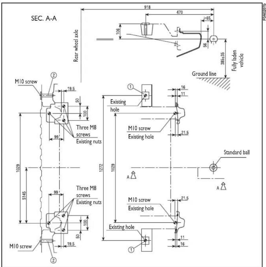
text_image
SEC. A-A Rear wheel axle 918 470 ≥65 106 385±35 Fully laden vehicle Ground line M10 screw ② 19.5 50 100 99 Three M8 screws Existing nuts 1029 5145 1272 1029 M10 screw Existing holes Existing hole Standard ball M10 screw Existing holes M10 screw Existing holes 19.5 100 50 ① ① 16 11 21.5 21.5 11 16 F0A0207bfig. 4
SNOW CHAINS
Use of snow chains should be in compliance with local regulations.
Snow chains should only be applied to the driving wheels (front wheels).
We recommend using Lineaccessori Fiat snow chains.
Check the tautness of the chains after driving some twenty to thirty metres.

With chains mounted keep your speed down.
Do not exceed 50 km/h. Avoid holes in the road; do not mount steps or kerbs. Do not drive long stretches of snow-free road with the chains mounted, as this can damage the vehicle and the road surface too.

Refer to the following table for information on the wheels where snow
chains can be fitted. Follow the prescriptions.
| Tyres on which chains can be fitted | Type of snow chains to be used |
| 185/65 R15 | Reduced clearance snow chains maximum projection off wheel equal to 12 mm. |
| 175/75 R14 | |
| 175/70 R14 |
SNOW TYRES
These tyres have been specially designed for driving on snow or ice, to be fitted in place of the standard tyres.
Use snow tyres of the same size as the standard tyres provided with the vehicle.
Fiat Dealership will be happy to provide advice concerning the most suitable type of tyre for the customer's requirements.
For the type of tyre to be used, inflation pressures and the specifications of snow tyres, follow the instructions given at paragraph “Wheels” in section “Technical Specifications”.
The winter features of these tyres are reduced considerably when the tread depth is below 4 mm. In this case, they should be replaced.
Due to the snow tyre features, under normal conditions of use or on long motorway journeys, the performance of these tyres is lower than that of standard tyres.
It is therefore necessary to limit their use to the purposes for which they are certified.
IMPORTANT When snow tyres are used with a max. speed index below the one that can be reached by the vehicle (increased by 5%), place a notice in the passenger compartment, plainly in the driver's view which states the max. permissible speed of the snow tyres (as per EC Directive).
All four tyres should be the same (brand and track) to ensure greater safety when driving and braking and better driveability.
Remember that it is inappropriate to change the direction of rotation of tyres.

The max. speed for snow tyres with "T" marking, is 190 km/h. The
Road Traffic Code speed limits must however be always strictly observed.
VEHICLE STORAGE
The following precautions should be taken if the vehicle will not be used for several months:
– Park the vehicle in covered, dry and if possible well-ventilated premises.
- Engage a gear.
- Make sure the handbrake is not engaged.
- Remove the cables from the battery terminals (first remove the cable to the negative terminal), and check the battery charge. If the vehicle is to be stored for long periods the charge of the battery should be checked every month and recharged if it falls below 12.5V.
IMPORTANT Where relevant, switch off the electronic alarm with the remote control.
– Clean and protect the painted parts using protective wax.
– Clean and protect the shiny metal parts using special compounds readily available.
- Sprinkle talcum powder on the rubber windscreen and rear window wiper blades and lift them off the glass.
– Slightly open the windows.
- Cover the vehicle with a cloth or perforated plastic sheet. Do not use sheets of non-perforated plastic as they do not allow moisture on the vehicle body to evaporate.
– Inflate the tyres to 0.5 bar above the normal specified pressure and check it at intervals. - Do not drain the engine cooling system.
IN AN EMERGENCY
EMERGENCY START-UP
If the Fiat code cannot deactivate the engine immobilising system, the warning lights 📄 (✗) and 📋 stay on and the engine will not start. Follow the emergency start-up procedure to start the engine.
Read the whole procedure carefully before trying to carry it out. If you make a mistake, you must turn the ignition key back to STOP and repeat the whole operation from the beginning (step 1).
I) Read the 5-figure electronic code given on the CODE card.
2) Turn the ignition key to MAR.
3) Press and hold down the accelerator pedal. The injection system warning light will come on for about 8 seconds, and then go out. At this point release the accelerator pedal and get ready to count the flashes of the injection warning light.
4) Count the number of flashes that corresponds to the first figure of the code on the CODE card, then press the accelerator pedal and keep it there until the warning light comes on for four seconds and then goes out; release the accelerator pedal.
5) The warning light will start flashing again: after it has flashed the number of times that corresponds to the second figure on the CODE card, press the accelerator pedal to the floor and keep it there.
6) Do the same for the remaining figures on the CODE card.
7) Once the final figure has been entered, keep the accelerator pedal pressed. The warning light will light up for four seconds and then go out; release the accelerator pedal.
8) The warning light will flash rapidly for about 4 seconds to indicate that the operation has been completed correctly.
9) Start the engine by turning the ignition key from MAR to AVV.
If, however, the warning light stays on, turn the ignition key to STOP and repeat the procedure from step I).
IMPORTANT After an emergency start-up, you should contact a Fiat Dealership otherwise you will have to repeat the procedure described each time you want to start the engine.
JUMP STARTING
If the battery is flat, you can use another battery to start the engine. Its capacity must be the same or slightly greater than the flat battery.
Proceed as follows fig. 1:
I) Connect positive terminals (+) of the two batteries with a jump lead.
2) With a second lead, connect the negative terminal (−) of the auxiliary battery and to an earthing point ↓ on the engine or the gearbox of the vehicle to be started.
IMPORTANT Do not directly connect the two negative terminals: sparks could ignite the flammable gas from the battery. If the other battery is fitted in a vehicle, prevent accidental contacts between the metal parts of the two vehicles.
3) Start the engine.
4) When the engine has been started, remove the leads reversing the order above.
If the engine fails to start after a few attempts, do not keep turning the key but have the vehicle seen to at a Fiat Dealership.
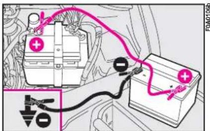
text_image
Diagram showing car battery connected to a power supply with labeled components and wiring connectionsfig. 1
Do not carry out this procedure if you lack experience; if it is not done correctly it can cause very intense electrical discharges. In addition, the fluid contained in the battery is poisonous and corrosive. Avoid contact with skin and eyes. You are also advised not to put naked flames or lighted cigarettes near the battery and not to cause sparks.
Under no circumstances should a battery charger be used to start the engine: it could damage the electronic systems and in particular the ignition and injection control units.
BUMP STARTING IF A TYRE IS PUNCTURED

Catalysed vehicles must not be bump started (pushed, towed or coasted down hill) as this could cause fuel to flow into the catalytic exhaust system and damage it beyond repair.

Remember that until the engine has started the brake booster and hydraulic power steering systems will not work and a greater effort will therefore be required to depress the brake pedal or turn the steering wheel.
GENERAL INSTRUCTIONS
Wheel changing and correct use of the jack and spare wheel call for some precautions as listed below.

Do not use the jack for loads over the value indicated on the plate.
The jack should only be used to change a wheel on the vehicle for which it was designed. It should not be put to other uses or employed to raise other models of vehicle. Under no circumstances should it be used when carrying out repairs under the vehicle.
An incorrectly positioned jack may cause the vehicle to fall.

Alert other drivers that the vehicle is stationary in compliance with local tions: hazard warning warning triangle etc.
Passengers on board should leave the vehicle, especially if it is heavily laden. Passengers should stay away from oncoming traffic while the wheel is being changed.
If the wheel is being changed on a steep or badly surfaced road, place wedges or other suitable material under the wheels to stop the vehicle.
The spare wheel is vehicle-specific. Never use the wheel on other models. Never fit other model spare wheels on your vehicle.

Do not lubricate the bolt threads before fitting them back: they could oose.
Fasten the wheel cap correctly to prevent the wheel from coming free in motion.
Never tamper with the inflation valve.
Never place tools between the rim and tyre.
Check the tyre and spare wheel pressure regularly. The tyre inflation pressure is shown in section "Technical specifications".
CHANGING A WHEEL
Please note:
- The jack weighs 1.85 kg
– The jack requires no adjustments - The jack cannot be repaired. If it breaks it must be replaced with a new jack
- No tool with the exception of the handle can be fitted on the jack.
To change a wheel proceed as follows:
1) Stop the vehicle in a position that is not dangerous for oncoming traffic where you can change the wheel safely. The ground should be flat and adequately firm.
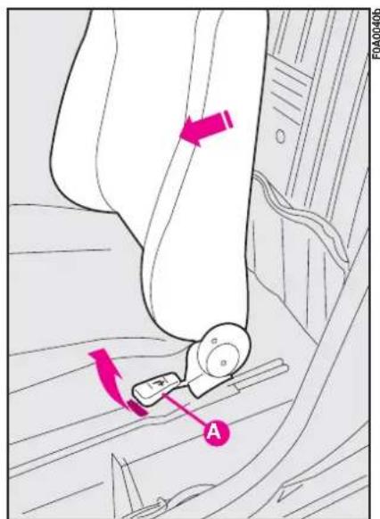
text_image
Diagram showing a device with labeled components and directional arrows, likely illustrating a mechanical or electrical system.fig. 2
2) Turn the engine off and pull up the handbrake.
3 Engage first or reverse gear.
4) Either move the left-hand front seat back forwards (Fiat Doblò Cargo versions) lifting lever A-fig. 2 and take the tool bag shown in fig. 3 or lift the rear seat (for Fiat Doblò Passenger Transport versions) with lever B-fig. 4 and take the bag shown in fig. 5. Take the bag to the wheel to be replaced.
5) Take the wheel removal wrench.
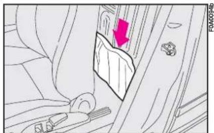
natural_image
Interior view of a vehicle showing a seatbelt with a red arrow pointing to the door panel (no text or symbols present)fig. 3
6) Loosen the bolt fastening the spare wheel with the wrench A-fig. 6.
IMPORTANT To reach the bolt, lift the flap on the panel.
7) Release the wheel from the safety wire and remove the wheel.
8) If the vehicle is fitted with alloy rims, shake the vehicle to facilitate removing the rim from the wheel hub.
9) Loosen the bolts on the wheel to be replaced with the tool provided.
10) Operate the handle A-fig. 7 to partially open the jack. Position the jack under the vehicle at the reference points A-fig. 8 near the wheel to be replaced.
II) Insert the handle and open the jack so that groove A-fig. 9 on the jack fits into the lower ribbing B on the sidemember.
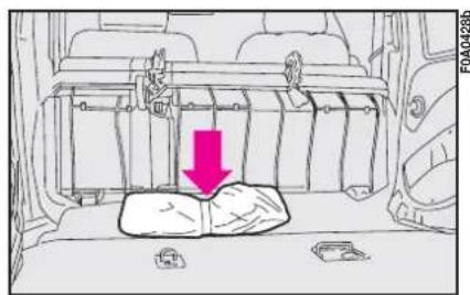
text_image
FOA0423bfig. 5
12) Alert other passengers that the vehicle is about to be raised; all persons should be kept away from the vehicle until it has been lowered.
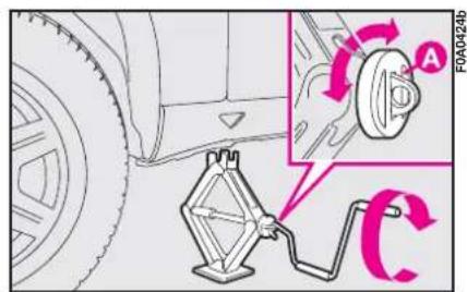
text_image
Diagram showing car wheel assembly with labeled components and rotation arrows, including a clamp mechanism.fig. 7
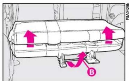
text_image
FOA0429b Bfig. 4
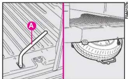
text_image
A FOA01076fig. 6
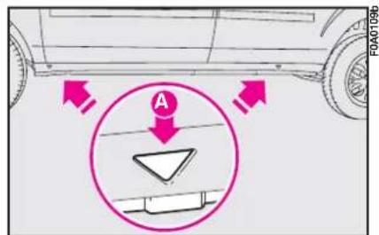
text_image
A FOA01096fig. 8
13) Operate the jack and lift the vehicle until the wheel to be changed is several centimetres off the ground. When turning the jack handle make sure that it can be used easily and take care not to scrape your hand against the ground. The moving parts of the jack (screw and joints) may also cause injury if touched. Clean off any grease.
14) Remove the four wheel bolts are remove the wheel.
15) Ensure that the housings for the wheel bolts on the spare wheel are clean and free from dirt which could cause the wheel bolts to come loose.
16) Fit the spare wheel making the holes A-fig. 10 coincide with the respective centring pins B.
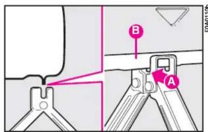
text_image
Technical diagram showing a mechanical assembly with labeled parts A and B, likely illustrating a tool or component assembly.fig. 9
17) Where relevant, take small wheel cup and fasten the four fastening screws.
18) Turn the jack handle to lower the vehicle and remove the jack.
19) Fasten bolts completely, working in a criss-cross fashion as shown in fig. 11.
20) To versions with large wheel cup, make symbol ☐ fig. 12 coincide with the inflation valve. Fasten the four bolts are shown in 19).
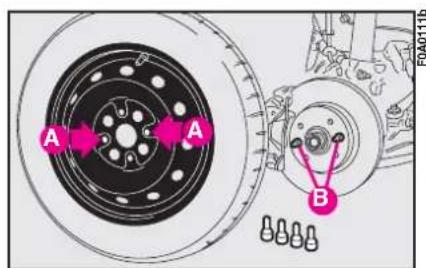
text_image
A A B F0A0111bfig. 10
When you have finished
I) Arrange the wheel you have replaced in the specific housing under the floor bed and secure the safety wire A-fig. 14a into clip B.
2) Hook the top of support bracket C-fig. 15 to the anchoring ring D and tighten the support locking bolt fig. 6.
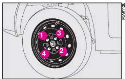
text_image
F0A012b 1 3 4 2fig. 11
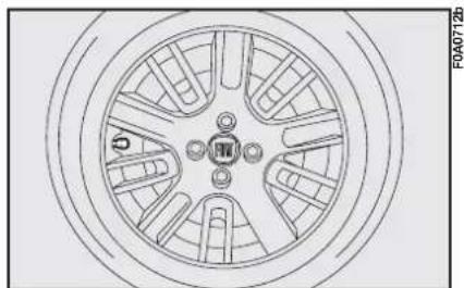
natural_image
Technical line drawing of a car wheel rim with mounting holes and hub (no text or symbols)fig. 12
In certain Passengers Transport versions instead of the traditional spare wheel, a space-saver spare wheel is provided. For anchoring to support proceed as follows:
- If the space-saver spare wheel is used, the spacer pad cannot be refitted on the outer side of the standard wheel rim but it shall be stowed temporarily in the luggage compartment.
- When fitting the space-saver spare wheel back onto container, fit the spacer tab on the outer side of the rim, then position the space-saver spare wheel with the outer side of the rim fig. 14b facing upwards
- hook the lower side of the support bracket C-fig. 16 to the anchoring spring D and tighten the support bolt fig. 6.
3) Put the jack and tools back in the tool bag.
4) Rearrange the tool bag behind the left-hand side seat (Fiat Dobló Cargo versions) or under the rear seat (Fiat Dobló Passengers Transport versions).
5) Fasten the bag with the elastic band.
IMPORTANT Do not use inner tubes with tubeless tyres.
Check the inflation pressure of the tyres and the spare wheel regularly.
Use the extension shown in fig. 13 to fasten or loosen the inflation valve cap.
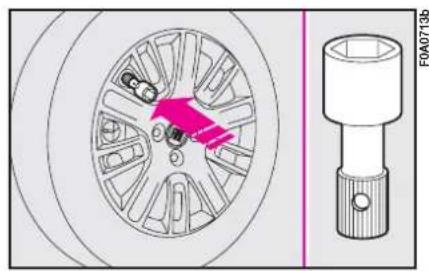
natural_image
Technical diagram of a car wheel and its internal components, showing a highlighted section with no visible text or symbols.fig. 13
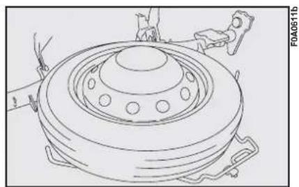
natural_image
Technical line drawing of a mechanical component with concentric rings and mounting brackets (no text or symbols)fig. 14b
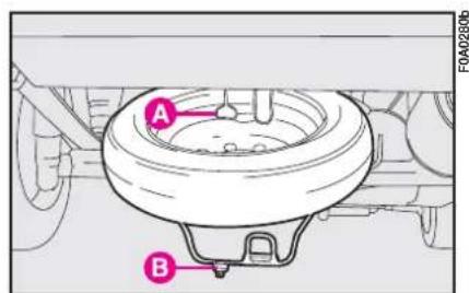
text_image
A B FOA0280bfig. 14a
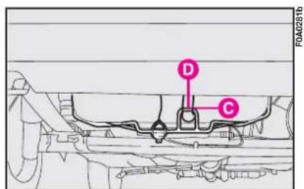
text_image
D C F0A0281bfig. 15
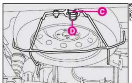
text_image
C D FA0610bfig. 16
QUICK TYRE REPAIR KIT FIX & GO automatic
The quick tyre repair kit Fix & Go automatic is placed in the boot into a proper container.
The kit includes fig. 16a:
- bottle A containing sealer and fitted with:
- filling pipe B
- sticker C bearing the notice "max. 80 km/h", to be placed in a position visible to the driver (on the instrument panel) after fixing the tyre
– instruction brochure fig. 16b, to be used for prompt and proper use of the quick repair kit and to be then handed to the personnel charged with handling the treated tyre
- compressor D including gauge and connections
- a pair of protection gloves located in the side space of the compressor
– adapters for inflating different elements.
In the kit container are also housed the screwdriver and the tow hitch.

Hand the instruction brochure to the personnel charged with treating re repaired with the kit.

In the event of a puncture caused by foreign bodies, it is possible to reres showing damages on ck or shoulder up to max diameter.
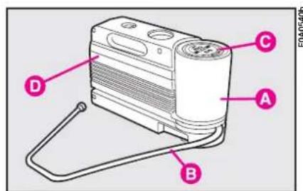
text_image
C A B D F0A05406fig. 16a
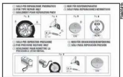
text_image
① SOLI PER REPROVASIONE PHOIMATICO ② FOR TYPE REPAIR ONLY ③ SEULEMENT POUR REPROVASION PNEU ④ NOR FOR REFERENCE REPAIR ⑤ SOLI PARA REPROVASIONES NEUMATICOS F0 3 A B C D E F G H I J K L M N O P Q R S T U V W X Y Z ① SOLI PER REPRESSION PRESSURE ② FOR PRESSURE RESTURE ONLY ③ SELEMENT POUR REMETTURE LA PRESSURE A CETAR INITIAL ④ NOR FOR DISCUSSIONE REPAIRING ⑤ SOLI PARA REPRESSION PRESSION F0 4fig. 16b

Holes and damages on the tyre side walls cannot be repaired. Do not use sick tyre repair kit if dams due to running with flat

Repairs are not possible in case of damages on the wheel rim (bad groove ion causing air loss). Do remove foreign bodies or nails) from the tyre.
IT SHOULD BE NOTICED THAT:
The sealing fluid of the quick tyre repair kit is effective with external temperatures between -20 °C and +50 °C.
The sealing fluid has limited life.

The compressor shall not be operated for more than 20 minutes. Risk of
overheating!. Tyres repaired with the quick tyre repair kit shall be used temporarily only.

The cylinder contains ethylene glycol. The cylinder contains latex: it can cause allergic reactions. It is harmful if ingested or inhaled and irritant for the eyes and in case of contact. In case of contact rinse immediately with water and take off contaminated clothes. If swallowed, do not induce vomit, rinse out the mouth, drink a lot of water and call the doctor immediately. Keep away from children. This product must not be used by asthmatics. Do not inhale vapours. Call the doctor immediately in case of allergic reactions. Keep the cylinder in the space provided for the purpose and far from heat. The sealing fluid has limited life.

Replace the cylinder if sealer has run out. Do not throw away the cylinder and the sealing fluid. Have the sealing fluid and the cylinder disposed of in compliance with national and local regulations.
INFLATING PROCEDURE

Put on the protection gloves provided together with quick tyre repair kit.
- Pull up the handbrake. Loosen tyre inflation valve cap, take out the filler hose A-fig. 16c and screw the ring nut B-fig. 16c on the tyre valve;
- make sure the compressor switch E-fig. 16f is set to 0 (off), start the engine and fit plug D-fig. 16e into the nearest current outlet and then turn on the compressor by setting switch E-fig. 16f to I (on). Inflate the tyre to the pressure specified in paragraph "Inflation pressure" in section "Technical Specifications". Check tyre pressure on gauge F with compressor off to obtain precise reading;
- if after 5 minutes it is still impossible to reach at least 1.5 bar, disengage compressor from valve and current outlet, then move the vehicle forth for approx. ten metres in order to distribute the sealing fluid inside the tyre evenly, then repeat the inflation operation;
- If after this operation it is still impossible after 5 minutes to reach at least 1.8 bar, do not start driving since the tyre is excessively damaged and the quick tyre repair kit cannot guarantee suitable sealing, contact Fiat Dealership;
- if reaching the tyre pressure specified in paragraph "Inflation pressure" in section "Technical Specifications", start driving immediately;
Apply the sticker in a visible position for the driver to indicate that the tyre has been treated with the quick tyre repair kit. Drive carefully especially when cornering. Do not exceed 80 km/h. Avoid heavy braking and accelerating.
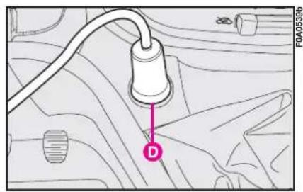
text_image
FA0539b Dfig. 16e
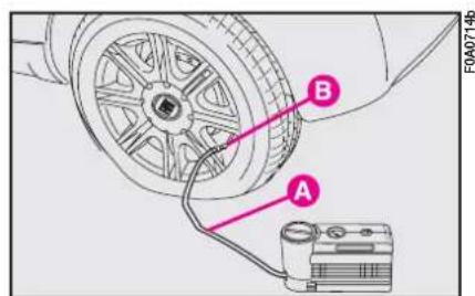
text_image
B A F0A0714bfig. 16c
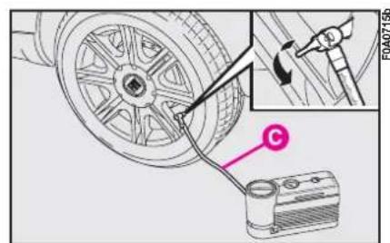
text_image
Technical diagram showing a car wheel being connected to a battery, with an inset close-up highlighting the mechanical component.fig. 16d
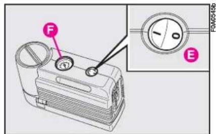
text_image
F E F0A0545bfig. 16f
- after driving for about 10 minutes stop and check again the tyre pressure; pull up the handbrake;
It is of vital importance to communicate that the tyre has been repaired using the quick tyre repair kit. Hand the instruction brochure to the personnel charged with treating the tyre repaired with the kit.

If the pressure falls below 1.8 bars, do not drive any further: the quick tyre repair kit Fix & Go automatic cannot guarantee proper hold because the tyre is too much damaged. Contact Fiat Dealership.
- if at least 1.8 bar pressure is read, restore proper pressure (with engine running and handbrake on) and restart;
– drive with the utmost care to the nearest Fiat Dealership.
FOR CHECKING AND RESTORING PRESSURE ONLY
The compressor can be also used just for restoring pressure. Disconnect the quick connection and connect it directly to the tyre valve; in this way the cylinder is not connected to compressor and the sealing fluid will not flow into the tyre.
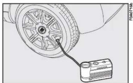
natural_image
Technical line drawing of a car wheel connected to a battery pack (no text or symbols)fig. 16g
CYLINDER REPLACEMENT PROCEDURE
To replace the cylinder proceed as follows fig. 16h:
- disconnect connection A; turn counter-clockwise the cylinder to replace and raise it; fit the new cylinder and turn it clockwise; connect connection A to the cylinder and fit the transparent tube B into the proper space.
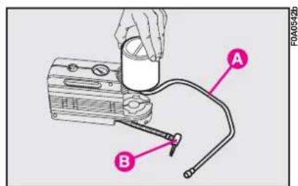
text_image
A B FOA0542bfig. 16h
IF A BULB BURNS OUT

Modifications or repairs to the electrical system carried out incorrectly and without bearing the features of the system in mind can cause malfunctions with the risk of fire.

Only touch the metal part when handling halogen bulbs. If the transparent bulb is touched it reduces the intensity of the light emitted and can also reduce the life of the bulb. If you touch the bulb accidentally, rub it with a cloth moistened with alcohol and leave it to dry.

You should have the bulbs replaced at a Fiat Dealership. Always check the height of the headlight beam after changing a bulb.

Halogen bulbs contain pressurised gas which, if broken, may cause small fragments of glass to be projected outwards.
GENERAL INSTRUCTIONS
- When a light is not working, check that it has not fused before changing the bulb.
- For the location of the fuses, refer to "If a fuse blows" in this chapter.
— Before replacing a bulb that does not work, check that the contacts are not oxidised. - Burnt-out bulbs must be replaced with ones of the same type.
- Always check the height of the headlight beam after changing a bulb.
IMPORTANT The headlight inner surface may be lightly misted over: this is not a fault but a natural fact due to low temperature and the level of air humidity. It will disappear as soon the headlights are turned on. The presence of drops inside the headlights means water infiltration, therefore contact Fiat Dealership.
TYPES OF BULBS
Several types of bulbs are installed in the vehicle fig. 17:
A Glass bulbs
Clipped into position. To remove them, pull.
B Bayonet connection bulbs
Remove from the bulb holder by pressing the bulb and turning it anticlockwise.
C Cylindrical bulbs
Remove by pulling away from terminals.
D-E Halogen bulbs
To remove the bulb, release the clip holding the bulb in place.
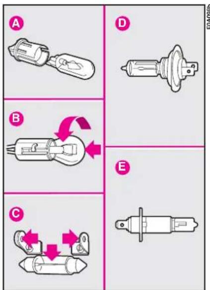
text_image
A B C D Efig. 17
| Bulb | Fig. 17 | Type | Power |
| Main beam headlights | E | H1 | 55W |
| Dipped beam headlights | D | H7 | 55W |
| Front sidelights | A | W5W | 5W |
| Front direction indicators | B | PY21W | 21W |
| Side direction indicators | A | W5W | 5W |
| Front fog lights | E | H1 | 55W |
| Taillights and brake lights | B | P21W/5W | 21/5W |
| Third brake light (supplementary brake lights) | B | P21W | 21W |
| Rear direction indicators | B | PY21W | 21W |
| Reversing light | B | P21W | 21W |
| Rear fog light | B | P21W | 21W |
| Number plate light | A | W5W | 5W |
| Ceiling light:– with toggle lens– with map reading light | C | C10W | 10W10W |
| Boot | A | W5W | 5W |
IF AN EXTERIOR LIGHT BURNS OUT

Alterations or repairs to the electric system not carried out correctly and without taking into account the system specifications may cause failures and the risk of fire.
MAIN BEAM HEADLIGHTS
To change the halogen bulb, proceed as follows:
I) Remove the protection cover C-
fig. 18 turning it counterclockwise;
2) Release clip A-fig. 19, remove connector B and remove the bulb C.
DIPPED BEAMS
To change the halogen bulb, proceed as follows:
I) Remove the protection cover B-fig. 18 turning it counterclockwise;
2) Release clip A-fig. 20, remove connector B and remove the bulb C.
See "If a bulb burns out" in this chapter for bulb type and power.
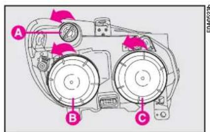
text_image
A B Cfig. 18
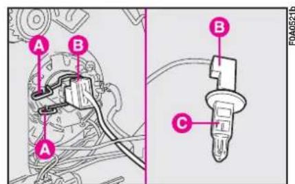
text_image
A B A B C F0A0521bfig. 19
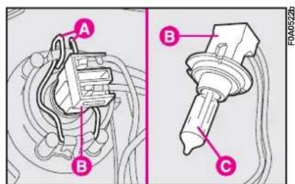
text_image
A B B C F0A0522bfig. 20
FRONT SIDELIGHTS
To change the bulb, proceed as follows:
I) Remove the protection cover B-fig. 18 turning it counterclockwise;
2) Press tabs A-fig. 21, remove the bulb holder from housing B and remove the bulb C (clipped in).
FRONT DIRECTION INDICATORS
To change the bulb, proceed as follows:
I) Turn the bulb holder A-fig. 18 and remove it.
2) Remove bulb by pushing it slightly and turning it anticlockwise (bayonet coupling).
FRONT FOG LIGHTS (where provided)
Contact Fiat Dealership to have front fog lights A-fig. 22 replaced.
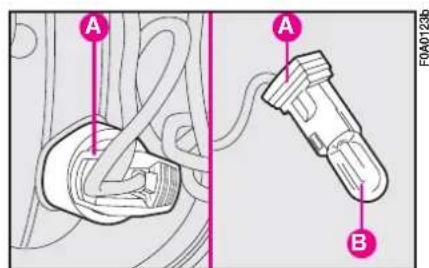
text_image
A A B FOA0123bfig. 21
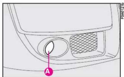
text_image
FA040121b Afig. 22
SIDE DIRECTION INDICATORS
To change the bulb, proceed as follows:
I) Press the lens A-fig. 24 in the direction of the arrow so to compress the clip and remove the cluster.
2) Turn the bulb holder counterclockwise, remove the snap-fitted bulb and replace it.
REAR LIGHT CLUSTER
To replace a bulb, proceed as follows:
Versions equipped with rear brackets:
1) Working inside the vehicle: remove the plastic cover fig. 25 set on the speaker seat fitting the screwdriver under the plastic and making it slide in parallel with the slot to spring the 2 front catches, pull the plastic cover parallel with the supporting surface to spring the rear catch and then remove the upper plastic cover A-fig. 26 using the screwdriver provided, in order to make visible the fastening bolt B of the light unit.
Versions not equipped with rear brackets:
1) Act from inside the vehicle to remove upper plastic cap C-fig. 27 by means of the screwdriver available, so that light cluster fastening bolt D is made visible.
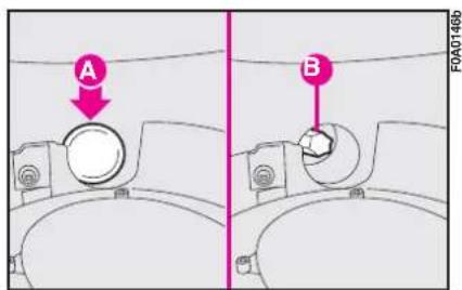
text_image
A B FOA0146bfig. 26
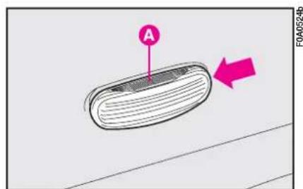
text_image
A F0A0524bfig. 24
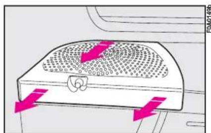
natural_image
Diagram of a car air vent with airflow arrows indicating flow direction (no text or symbols)fig. 25
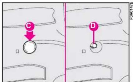
text_image
C D F0A040147bfig. 27
2) Fit the wrench provided A-fig. 28 (used also to remove the wheel) to the fastening bolt of the light unit.
3) Loosen the bolts, then undo the light cluster fastening nuts by means of extension B-fig. 28 supplied with the unit.
As regards the 7-seater version is concerned, undo the light cluster fastening bolt by means of extension B-fig. 28 inserted onto the bolt through slotted hole C-fig. 28a.
4) Undo, after removing the fastening bolt, the cluster fastening screws (located outside), as illustrated in fig. 29.

text_image
A B FOA0401bfig. 28
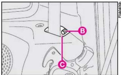
text_image
B C FOA0406bfig. 28a
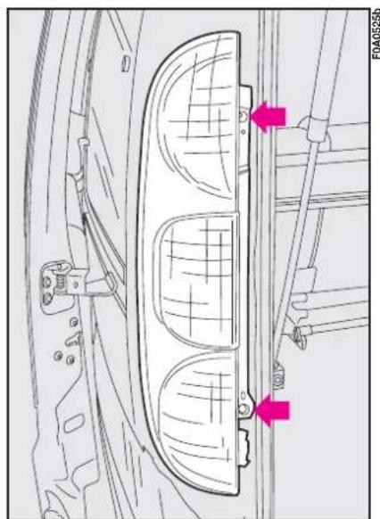
natural_image
Technical line drawing of a car front panel with two pink arrows pointing to specific components (no text or symbols present)fig. 29
5) Take out the pressure-fit connector.
6) Undo the four fastening screws to remove the bulb holder and get access to the bulbs.
7) Remove the bulbs fig. 30 by pushing them gently and turning them counterclockwise (bayonet fitting)
A – brake light bulb
B – indicator light bulb
C – reversing light bulb
D – sidelight bulb
E - rear fog light bulb
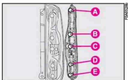
text_image
A B C D E F0A0528bfig. 30
THIRD BRAKE LIGHTS
To replace a bulb, open either the left-hand door or the tailgate and loosen the screws A-fig. 31.
Remove the lens from its housing from the outside.
Remove the clipped-on bulb B-fig. 32 and replace it.
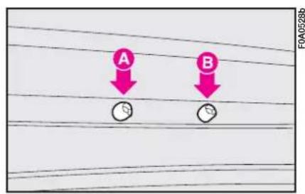
text_image
A B F0A0528bfig. 31
NUMBER PLATE LIGHT
To replace a bulb, press the tab in the point shown in fig. 33 and remove the cluster. Turn the bulb holder A-fig. 34 anticlockwise and remove bulb B.
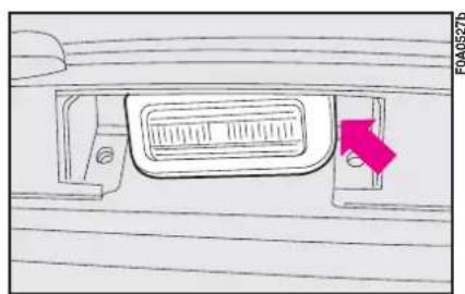
natural_image
Technical line drawing of a mechanical component with a highlighted arrow (no text or symbols)fig. 33
IF AN INTERIOR LIGHT BURNS OUT

Modifications or repairs to the electrical system carried out incorrectly and without bearing the features of the system in mind can cause malfunctions with the risk of fire.
See "If a bulb burns out" in this chapter for bulb type and power.
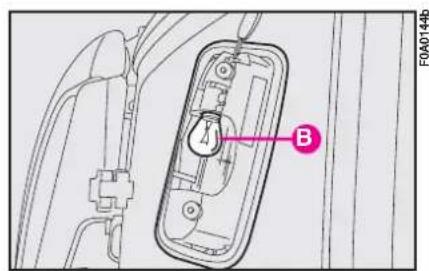
text_image
F0A0144b Bfig. 32
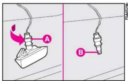
text_image
A Bfig. 34
CEILING LIGHTS
With toggling lens
To replace a bulb:
I) Remove the ceiling light fig. 35 by releasing the clipped on lens frame in the point shown by the arrow.
2) Open the container A-fig. 36 and replace the burnt-out bulb.
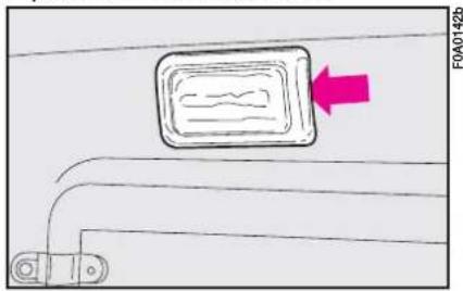
text_image
F0A0142bfig. 35
With map reading lights
To replace a bulb:
1) Remove the ceiling light A-fig. 37 by releasing the clipped on lens frame in the point shown by the arrow.
2) Open the bulb container A-fig. 38.
3) Replace the burnt out bulb.
BOOT LIGHT
To replace the bulb:
I) Remove the lens A-fig. 39 as shown by the arrow.
2) Open the bulb holder B and remove the bulb C (clipped in).
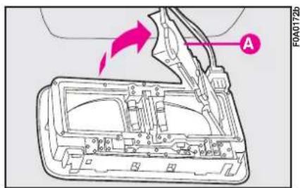
text_image
A FOA0172bfig. 38
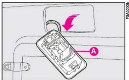
text_image
F0A0200b Afig. 36
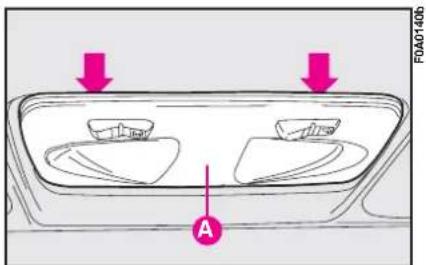
text_image
A FOA01406fig. 37
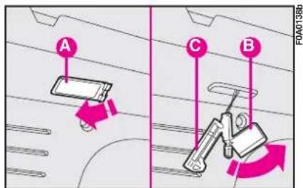
text_image
A C B F0A0138bfig. 39
IF A FUSE BLOWS
GENERAL
A fuse is an element for protecting the electrical system. A fuse will trip (i.e. it will blow) in the event of a failure or improper interventions in the electrical system.
If an electrical device is not working, check whether the respective fuse is blown. The conductor A-fig. 40 should be intact. If it is not, replace the fuse with another with the same amperage (same colour).
B - Undamaged fuse.
C - Fuse with broken filament.
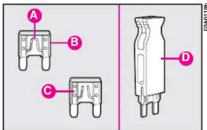
text_image
A B C D F0A01186fig. 40
Remove the blown fuse with the tongs provided D, which can be found in the fusebox.

Never replace a broken fuse with anything other than a new fuse. Always fuse of the same colour.

Never change a fuse with another amperage: FIRE RISK.

Do not attempt to re-pair a blown MAXI-FUSE. Go to a Fiat Dealership.

Before changing a fuse, check the ignition key has been removed and that other electric devices have turned off/disabled.

If the fuse blows again, have the vehicle inspected at a Fiat Dealership.
The fuses in the Fiat Doblò are grouped in two fuseboxes, one located in the dashboard and the other in the engine compartment.
Press in the points shown in fig. 41 to remove the cover and reach the fuses.
Refer to the table on the following pages to identify the fuses.
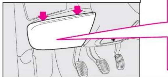
natural_image
Diagram of a vehicle's seat and dashboard with directional arrows indicating movement (no text or labels)fig. 41
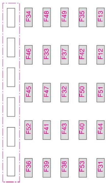
text_image
F36 F52 F45 F46 F34 F39 F41 F47 F33 F48 F38 F43 F32 F37 F49 F53 F40 F50 F42 F35 F31 F44 F51 F12 F13To reach the fuses in the engine compartment fusebox, release the tabs A-fig. 42 and remove the cover B.
Refer to the table on the following pages to identify the fuses.
NOTE: The glow plug fuse (60 A) is built into the pre-cabled section but it is positioned aside the engine compartment fuse box inside the cover shell so it can be friendly reached.
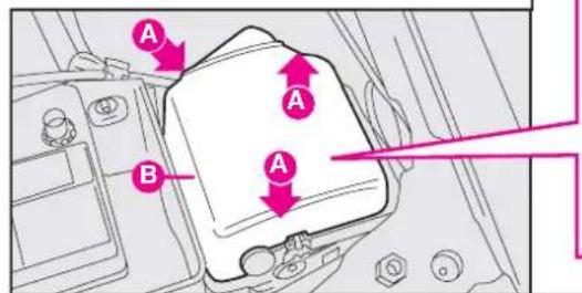
text_image
A A B Afig. 42
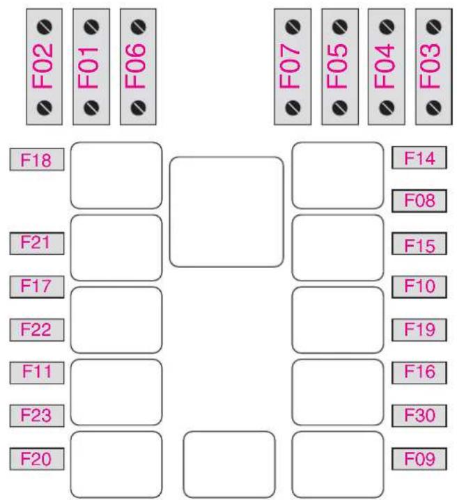
text_image
F02 F01 F06 F18 F21 F17 F22 F11 F23 F20 F07 F05 F04 F03 F14 F08 F15 F10 F19 F16 F30 F09F0A0152b
FUSE SUMMARY TABLE
| Figure Fuse Ampere | |||
| Right-hand main beam | 42 | F14 | 10 |
| Left-hand main beam | 42 | F15 | 10 |
| Right-hand dipped beam | 41 | F12 | 10 |
| Left-hand dipped beam | 41 | F13 | 10 |
| Boot | 41 | F42 | 10 |
| Hazard lights | 41 | F53 | 10 |
| Front fog lights | 42 | F30 | 15 |
| Direction indicators | 41 | F53 | 10 |
| Dashboard instrument lights | 41 | F51 | 7.5 |
| Light system | 41 | F32 | 15 |
| Ceiling light | 41 | F42 | 10 |
| Instrument panel and warning lights (ignition switch powered) | 41 | F37 | 10 |
| Instrument panel and warning lights (battery powered) | 41 | F53 | 10 |
| Reversing light | 41 | F31 | 7.5 |
| Brake lights | 41 | F37 | 10 |
| Number plate light | 41 | F51 | 7.5 |
| Additional brake light (third stop light) | 41 | F37 | 10 |
| Cigar lighter | 41 | F44 | 20 |
| Air bag | 41 | F50 | 7.5 |
| Dashboard control unit power: optional functions | 42 | F02 - MAXI FUSE | 40 |
| Dashboard control unit power: standard functions | 42 | F01 - MAXI FUSE | 70 |
| ABS power (pump) | 42 | F04 - MAXI FUSE | 40 |
| Right front power window | 41 | F48 | 20 |
| Left front power window | 41 | F47 | 20 |
| Door locking system | 41 | F38 | 20 |
| Ignition coils | 42 | F22 | 20 |
| Engine control system secondary loads | 42 | F11 | 15 |
| ABS control unit (ignition switch powered) | 41 | F42 | 7.5 |
| Engine control unit (+battery) | 42 | F18 | 7.5 |
Figure Fuse Ampere
| Engine control unit (power) | 42 | F17 | 10 |
| Engine control unit (ignition switch powered) | 42 | F16 | 7.5 |
| Glow plug control unit | 42 | F11 | 15 |
| Horn | 42 | F10 | 15 |
| Manual climate control enable control | 41 | F31 | 7.5 |
| Ignition switch | 42 | F03 - MAXI FUSE | 20 |
| Manual climate control compressor | 42 | F19 | 7.5 |
| Headlight beam adjuster | 41 | F13 | 10 |
| Petrol fume recirculation solenoid valve | 42 | F11 | 15 |
| Tachometer generator | 42 | F11 | 15 |
| Injectors | 42 | F22 | 20 |
| Heated rear window | 41 | F40 | 30 |
| One-speed radiator fan | 42 | F06 - MAXI FUSE | 30 |
| Fuel pump | 42 | F22 | 20 |
| Fuel pump | 42 | F21 | 15 |
| Windscreen-rear window washer pump | 41 | F43 | 30 |
| Supplementary power socket | 41 | F44 | 20 |
| ABS power (valve) | 42 | F05 - MAXI FUSE | 30 |
| Radiator fan first speed (versions with manual climate control system) | 42 | F06 - MAXI FUSE | 30 |
| Radiator fan first speed (1.3 -1.9 Multijet versions) | 42 | F06 - MAXI FUSE | 40 |
| Radiator fan second speed (1.4 - 1.6 versions with manual climate control system) | 42 | F07 - MAXI FUSE | 60 |
| Radiator fan second speed (1.3 -1.9 Multijet versions) | 42 | F07 - MAXI FUSE | 40 |
| Heated seats | 41 | F45 | 15 |
| + 30 services (sound system, cellular telephone, diagnostic socket) | 41 | F39 | 10 |
Figure Fuse Ampere
| +15 services (sound system, cellular telephone, dashboard control lighting, electrical mirrors, trailer, heated seat control lighting) | 41 | F49 | 7.5 |
| Lambda sensors (oxygen sensors) | 42 | F11 | 15 |
| Heated rearview mirrors | 41 | F41 | 7.5 |
| Engine cooling system relay | 42 | F18 | 7.5 |
| Engine control system relay | 42 | F16 | 7.5 |
| Pump system relay | 41 | F31 | 7.5 |
| Fan system relaypassenger compartment heater | 41 | F31 | 7.5 |
| Safet belt buzzer muting relay | 41 | F49 | 7.5 |
| Windscreen wiper | 41 | F43 | 30 |
| Rear window wiper | 41 | F52 | 15 |
| Passenger compartment fan | 42 | F08 | 30 |
| Subwoofer system | 41 | F36 | 15 |
| Spare | 41 | F35 | - |
| Spare | 42 | F09 | - |
| Spare | 41 | F33 | - |
| Spare | 41 | F34 | - |
| Spare | 41 | F46 | - |
| Spare | 42 | F23 | - |
IF THE BATTERY IS FLAT
First of all, read the “Vehicle maintenance” section for the steps to be taken to avoid the battery running down and to ensure it has a long life.
IF THE BATTERY IS FLAT
Charging should be slow at a low amp rating for 24 hours. Charging for a longer time may damage the battery.
Proceed as follows:
I) Disconnect the electrical system from the battery terminals.
IMPORTANT Where relevant, switch the electronic alarm off with the remote control.
2) Connect the charger cables to the battery terminals.
3) Turn on the charger.
4) When you have finished, turn the charger off before disconnecting the battery.
5) Reconnect the cables to the battery terminals. Make sure the polarity is correct.

The liquid in the battery is poisonous and corrosive. Do not let it touch the skin or eyes. Recharging the battery should be done in a well-ventilated area away from naked flames or possible sources of sparks: explosion and fire risk.
JUMP STARTING
See "Jump starting", in this chapter.

Do not attempt to recharge a frozen battery. Thaw it first otherwise it could explode. If the battery froze, make sure that the internal elements are not broken (short-circuit risk) and that the casing is not cracked (risk of spilling the poisonous and corrosive fluid).

Under no circumstances should a battery charger be used to start the engine: it could damage the electronic systems and in particular the ignition and injection control units.
JACKING THE VEHICLE
WITH THE JACK
See "If a tyre is punctured", in this section.
An incorrectly positioned jack may cause the vehicle to fall. Do not use the jack to lift loads exceeding that indicated on the label attached to the jack itself.
WITH A SHOP JACK
From the front
Jack up the vehicle only by positioning the jack arm at the gearbox/differential and placing a rubber pad in between, as shown in fig. 43.

The jack should only be used to change a wheel on the vehicle for which it
was designed. It should not be put to other uses or employed to raise other models. Under no circumstances should it be used when carrying out repairs under the vehicle.
Please note:
– The jack requires no adjustments.
- The jack cannot be repaired. If it breaks it must be replaced with a new jack;
- No other tool, part from the handle shown in this chapter, can be fitted to the jack.
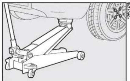
natural_image
Technical line drawing of a vehicle suspension system with a tire and car (no text or symbols)fig. 43
From the side
Jack up the vehicle only by positioning the jack arm at the gearbox/differential and placing a rubber pad in between, as shown in fig. 44.
WITH AN ARM HOIST
Jack up the vehicle by arranging the ends of the arms in the areas shown in fig. 45.
TOWING THE VEHICLE
A tow hitch is provided with the vehicle.
To fasten the tow hitch:
I) Remove the tow ring from the tool bag.
2) Remove the flap fig. 46 on the bumper levering with a screwdriver in the point shown by the arrow.
3) Fasten the hitch A-fig.46 on the threaded pin.
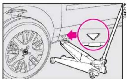
text_image
F0A0717bfig. 44
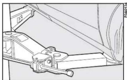
natural_image
Technical line drawing of a mechanical assembly with no visible text or symbolsfig. 45
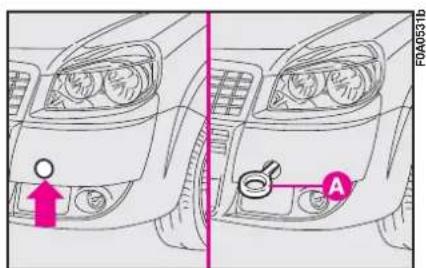
text_image
FA040531bfig. 46
B-fig. 47 - Rear ring for towing another vehicle.
Before starting to tow, turn the ignition key to MAR and then to STOP. Do not remove the key. If the key is removed, the steering lock engages automatically which prevents the wheels being turned.
When towing the vehicle, you must comply with the specific traffic regulations regarding the tow hitch and how to tow on the road.
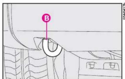
text_image
B F0A04176fig. 47
While the vehicle is being towed with the engine off, remember that the brake pedal and steering will require more effort as you no longer have the benefit of the power brakes and power steering. Do not use flexible cables to tow. Avoid jerking. Whilst towing, ensure that the coupling to the vehicle does not damage the surrounding components.
IF AN ACCIDENT OCCURS
– It is important to keep calm.
- If you are not directly involved in the accident, stop at least ten metres away from the accident.
- If you are on a motorway, do not obstruct the emergency lane with your vehicle.
– Turn off the engine and turn on the hazard lights. - At night, illuminate the scene of the accident with your headlights.
- Act carefully, you must not risk being run over.
- Mark the accident by putting the red triangle at the regulatory distance from the vehicle where it can be clearly seen.
- Call for rescue making the information you give as accurate as you can. On the motorway use the special column-mounted emergency phones.
- In pile-ups on the motorway, particularly when the visibility is bad, there is a high risk of other vehicles running into those already stopped. Get out of the vehicle immediately and take refuge behind the guard rail.
- If the doors are blocked, do not attempt to smash the windscreen to get out of the vehicle. It is made of layered glass and is very hard. Side and rear windows are much more easily broken.
- Remove the ignition keys from the vehicles involved.
- If you can smell petrol or other chemicals, do not smoke and make sure all cigarettes are extinguished.
- Use a fire extinguisher, blanket, sand or earth to put out fires no matter how small they are. Never use water.
IF ANYONE IS INJURED
- Never leave the injured person alone. The obligation to provide assistance exists even for those not directly involved in the accident.
- Do not congregate around the injured person.
– Reassure the injured person that help is on its way and will arrive soon. Stay close by to calm him/her down in case of panic.
– Unfasten or cut seat belts holding injured parties. - Do not give an injured person anything to drink.
- Do not move an injured person unless the following situations arise.
– Pull the injured person from the vehicle only if it risks catching fire, it is sinking in water or is likely to fall over a cliff or similar. Do not pull his/her arms or legs, do not bend the head and, as far as possible, keep the body horizontal.
FIRST-AID KIT
It is a good idea to keep a fire extinguisher and blanket in the vehicle in addition to the first-aid kit.
The first aid kit can be arranged on the shelf as shown in fig. 48.
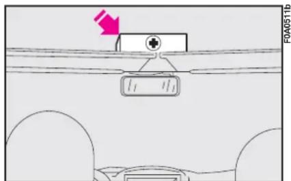
text_image
F0A0511bfig. 48
VEHICLE MAINTENANCE
SCHEDULED SERVICING
Correct maintenance of the vehicle is essential for ensuring it stays in tip-top condition for a long time to come.
This is why Fiat has programmed a series of checks and maintenance operations every 20,000 km.
It is however important to remember that scheduled servicing is not all your vehicle requires. Regular checked - also in the initial period before the 20,000 kilometre coupon and later between coupons - ordinary care is required, such as checking fluid levels and topping up, checking tyre inflation pressure, etc...
IMPORTANT The Manufacturer requires the Service Schedule coupon-related checks to be carried out. Failure to do so could result in the warranty being cancelled for those defects that can be attributed to such failure.
Scheduled Servicing is performed at all Fiat Dealerships and there is a set time scale for such operations.
If during each operation, in addition to the ones programmed, the need arises for further replacements or repairs, these may be carried out only with the explicit agreement of the Customer.
IMPORTANT You are recommended to get in touch with a Fiat Dealership immediately if any minor running problems crop up without waiting for the next coupon.
SERVICE SCHEDULE
The scheduled service must be carried out every 20,000 km.
(*) Or every 4 years for very demanding use (cold climate, idling in city traffic, dusty areas).
| thousands of kilometres | 20 | 40 | 60 | 80 | 100 | 120 | 140 | 160 | 180 | |||
| Check tyre conditions / wear and adjust pressure, if required | ● | ● | ● | ● | ● | ● | ● | |||||
| Check lighting system operation (headlights, direction indicators,hazard lights, boot light, passenger's compartment lights,glove compartment light, instrument panel warning lights, etc.) | ||||||||||||
| ● | ● | ● | ● | ● | ● | ● | ||||||
| Check windscreen wiper/washer operation, adjust nozzles | ● | ● | ● | ● | ● | ● | ● | |||||
| Check windscreen/rear window wiper blade position/wear | ● | ● | ● | ● | ● | ● | ● | |||||
| Check front disk brake pad conditions and wear | ● | ● | ● | ● | ● | ● | ● | |||||
| Check rear drum brake lining conditions and wear | ● | ● | ● | |||||||||
| Inspect conditions of: underbody protection, piping (exhaust - fuel feed and brakes), rubber parts (boots, sleeves, bushings, etc.), fuel feed and braking system hosing | ||||||||||||
| ● | ● | ● | ● | ● | ● | ● | ||||||
| Check cleanness of locks, bonnet and boot and levercleanness and lubrication | ● | ● | ● | ● | ● | ● | ● | |||||
| Sight inspect accessory drive belt conditions | ● | ● | ||||||||||
| Replace accessory drive belts | ● | |||||||||||
| Check/adjust tappet clearance (1.4 8V and 1.9 Multijet versions) | ● | ● | ● | |||||||||
| Check and adjust handbrake lever stroke | ● | ● | ● | ● | ||||||||
| Check exhaust gas/smokiness (diesel versions) | ● | ● | ● | ● | ||||||||
| Check anti-evaporation system | ● | ● | ||||||||||
| Replace fuel filter (Multijet versions) | ● | ● | ● | |||||||||
| Replace air cleaner cartridge (petrol versions) | ● | ● | ● | ● | ||||||||
| Replace air cleaner cartridge (Multijet versions) | ● | ● | ● | |||||||||
| Top up fluids (engine coolant, brakes, windscreen washer, battery, etc.) | ● | ● | ● | ● | ● | ● | ● | ● | ||||
| Check timing belt conditions (excluding 1.3 Multijet versions) | ● | ● | ||||||||||
| Replace timing belt (excluding 1.3 Multijet versions) (*) | ● | |||||||||||
| Replace spark plugs (petrol versions) | ● | ● | ● | ● | ||||||||
| Check engine control systems (via diagnostic socket) | ● | ● | ● | ● | ||||||||
| Check mechanical transmission oil level | ● | ● | ||||||||||
| Change engine oil and oil filter (versions without DPF) (▼) | ● | ● | ● | ● | ● | ● | ● | ● | ||||
| Change engine oil and oil filter (Multijet versions with DPF) (or every 2 years) (***) | (●) | (●) | (●) | (●) | (●) | (●) | (●) | (●) | ||||
| Change brake fluid (or every 2 years) | ● | ● | ● | |||||||||
| Change pollen filter (or every 2 years) | ● | ● | ● | ● | ● | ● | ● | ● |
Or every 5 years, regardless from the distance travelled.
(▼) Every 30.000 km or 2 years for Multijet versions
(* *) Engine oil and oil filter shall be changed according to their actual exhaust conditions, indicated by warning light/message (where provided) on the instrument panel (see section “Warning lights and messages”).
ANNUAL INSPECTION SCHEDULE
For vehicles with an annual mileage of below 20.000 km (for example about 10.000 km) the following yearly inspection programme is advised:
- check tyre conditions/wear and adjust pressure if required (including the spare wheel).
- check light system operation (headlights, direction indicators, hazard lights, boot lights, passenger compartment lights, glovebox light, warning lights, etc.).
- check windscreen wiper/washer operation, adjust nozzles.
- check windscreen/rear window blade position/wear
- check front disk brake pad conditions and wear.
– check cleanness of bonnet and boot locks and lever cleanness and lubrication
- sight inspect the conditions of: engine, gearbox, transmission, pipes and hoses (exhaust - fuel - brakes), rubber parts (boots, sleeves, bushes, etc) brake and fuel hoses.
– check battery charge.
– visual check on various drive belt conditions.
- check and top up, if required, fluid levels (engine coolant, brake fluid, windscreen washer fluid, battery fluid, etc.).
- change engine oil.
– change engine oil filter. - replace pollen filter (where provided).
ADDITIONAL CHECKS
Every 1,000 km or before long trips, check and top up as necessary: engine coolant level, brake fluid level, windscreen washer liquid level, tyre pressure and conditions.
Every 3,000 km check and top up as necessary: engine oil level.
You are recommended to use FL Selenia, products designed and produced specifically for Fiat vehicles (see "Capacities" in section "Technical specifications").
IMPORTANT - Engine oil
Should prevailing use of the vehicle be under one of the following specially heavy conditions:
- towing a trailer
- on dirty roads
– for short, repeated trips (less than 7-8 km) with outside temperature below zero
– frequently idling engines or long distance low speed driving (e.g. taxis or door-to-door deliveries) or in case of a long term inactivity; replace engine oil more frequently than required on Service schedule
IMPORTANT - Air cleaner
If the vehicle is used on dusty roads change the air cleaner more frequently than the indications in the Service schedule. If in doubt as to how often the engine oil and air cleaner should be changed according to how you use the vehicle, contact a Fiat Dealership.
IMPORTANT - Pollen filter
If the vehicle is used frequently in dusty or heavily polluted environments it is advisable to replace the filtering element more frequently; in particular it should be replaced if a reduction of the amount of air admitted to the passenger compartment is noted.
IMPORTANT - Battery
The charge in your battery should be checked, where possible at the start of the winter, to limit the risk of the battery electrolyte freezing. This check should be carried out more frequently if the vehicle is mainly used for short trips or if it is fitted with accessories that permanently take in electricity even when the ignition key is removed, especially in the case of after market accessories.
You should check the battery fluid (electrolyte) level more frequently than shown in the service schedule in this chapter if the vehicle is used in hot climates or particularly demanding conditions.

Maintenance of your vehicle should be entrusted to a Fiat Dealership. For ordinary routine maintenance operations which you are able to carry out yourself, ensure that you have the necessary tools and original Fiat spare parts and fluids available. Do not carry out servicing operations if you have no experience.
CHECKING THE LEVELS
- Engine oil - 2. Battery - 3. Brake fluid - 4. Windscreen washer fluid - 5. Engine coolant - 6. Power steering fluid.

Do not smoke while working in the engine compartment: the pres-of flammable gas and could cause a fire.

Be careful not to mix up the various types of fluids when you are topping up: re all mutually incompatible could damage the vehicle.
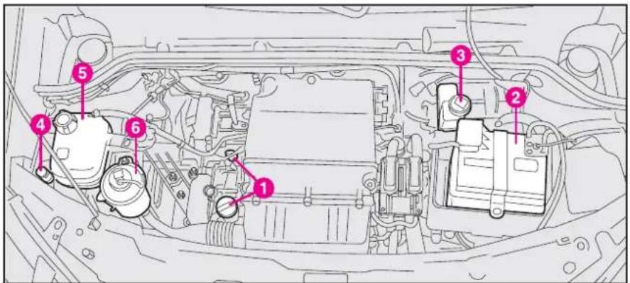
text_image
Technical diagram of a car engine bay with numbered components for identificationfig. 1 - 1.4 8V versions
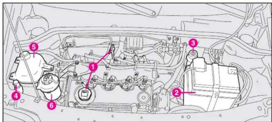
text_image
Technical diagram of a car engine bay with numbered components for identificationfig. 2 - 1.9 Multijet versions
- Engine oil - 2. Battery - 3. Brake fluid - 4. Windscreen washer fluid - 5. Engine coolant - 6. Power steering fluid.

Do not smoke while working in the engine compartment: the pres-of flammable gas and could cause a fire.

Be careful not to mix up the various types of fluids when you are topping up: we all mutually incompatible could damage the vehicle.
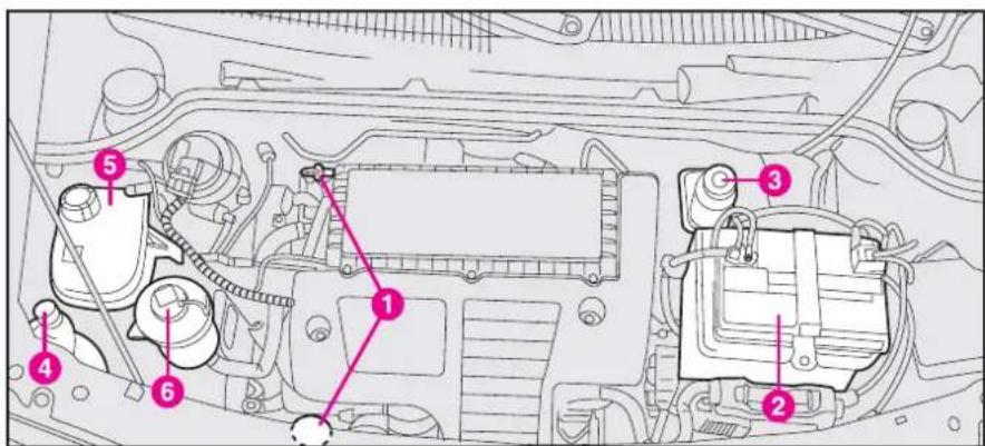
text_image
Technical diagram of a car engine bay with numbered components for identificationfig. 3 - 1.3 Multijet versions
- Engine oil - 2. Battery - 3. Brake fluid - 4. Windscreen washer fluid - 5. Engine coolant - 6. Power steering fluid.

Do not smoke while working in the engine compartment: the pres-of flammable gas and could cause a fire.

Be careful not to mix up the various types of fluids when you are topping up: e all mutually incompatible could damage the vehicle.
ENGINE OIL fig. 6, 7, 8
Check engine oil with the vehicle on level ground and while the engine is still warm (approximately 5 minutes after stopping the engine.
The oil level should be included between the MIN and MAX reference marks on the dipstick.
The space between MIN and MAX equals about 1 litre of oil.

Be very careful under the bonnet: you risk burning yourself. Remember when the engine is hot, the n start up and cause in-

Do not add oil with different specifications from the oil already in the en-
If the oil level is near or actually below the MIN mark, add oil through the filler until it reaches the MAX mark.
Oil level shall never exceed the MAX mark.
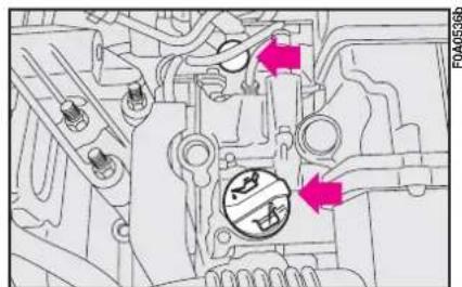
text_image
F0A0536bfig. 6 - 1.4 8V versions
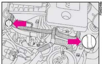
natural_image
Mechanical engine diagram showing hoses and components with pink arrows indicating flow direction (no text or labels)fig. 7 - 1.3 Multijet versions
IMPORTANT If, following a check the engine oil if move the MAX level, go to a Fiat Dealership to have the correct level restored.
IMPORTANT After topping up or changing the oil, let the engine turn for a few seconds and wait a few minutes after stopping it before you check the level.
ENGINE OIL CONSUMPTION
Max engine oil consumption is usually 400 grams every 1000 km.
During the beginning of the vehicle's life the engine is be tuned in. Engine oil consumption can only be considered stabilised after the first 5000 ÷ 6000 km.
IMPORTANT Oil consumption depends on the driving style and the conditions of use.
Used engine oil and replaced oil filters contain substances which can harm the environment. We recommend you have the vehicle seen to at a Fiat Dealership for the oil and filter change. It is suitably equipped for disposing of used oil and filters in an environmentally-friendly way that complies with the law.
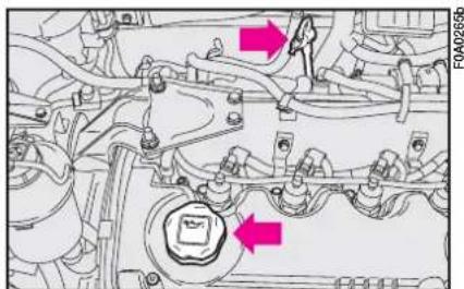
text_image
Technical diagram of an engine cylinder with two highlighted components and directional arrows indicating flow or movement.fig. 8 - 1.9 Multijet versions
ENGINE COOLANT fig. II
The coolant level shall be checked with cold engine and shall be within the MIN and MAX marks on the tank.
If the level is low, pour slowly a mixture of 50% distilled water and 50% PARAFLU UP of the FL Selenia Group through the filler neck until the level reaches MAX.
A 50-50 mixture of PARAFLU UP and distilled water gives freeze protection to -35^ .
For particularly hard climate conditions, we recommend use of a 60% PARAFLU UP and 40% demineralized water mixture.

The engine cooling system uses protective antifreeze fluid PARAFLU UP. Use the same fluid type as that already in the cooling system when topping up. PARAFLU UP fluid cannot be mixed with any other type of fluid. Should it happen, under no circumstances start the engine; contact a Fiat Dealership.
WINDSCREEN/REAR WINDOW WASHER FLUID
To top up, remove the cap A-fig. 12 and lift the telescopic filler B, until it clicks.
Pour a mixture of water and TUTELA PROFESSIONAL SC 35, in the following concentrations:
30% of TUTELA PROFESSIONAL SC 35 and 70% of water in summer; 50% of TUTELA PROFESSIONAL SC 35 and 50 of water in winter. If the temperature falls below -20°C, use TUTELA PROFESSIONAL SC 35 undiluted.
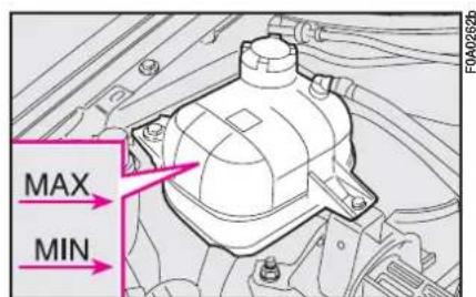
text_image
MAX MINfig. 11
The cooling system is pressurised. If necessary, replace the cap only with another genuine one, otherwise system efficiency could be compromised. Do not remove the reservoir cap when the engine is hot: you risk scalding yourself.
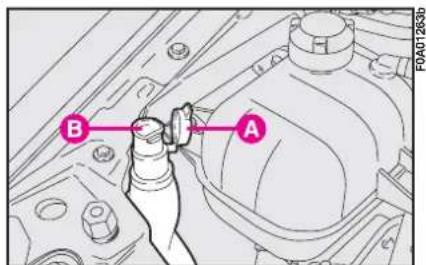
text_image
B A F0A01263bfig. 12

Do not travel with the windscreen washer reservoir empty. The windscreen washer is fundamental for improving visibility.
POWER STEERING FLUID
fig. 13
The oil level with the vehicle on level ground and engine cold should be included between the references MIN and MAX on the reservoir.
When the oil is hot, the level can exceed the reference line MAX.
When topping up (where necessary) make sure that the oil has the same specifications as the oil in the system.
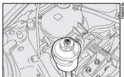
natural_image
Technical line drawing of a mechanical assembly with no visible text or symbolsfig. 13

Do not let the power steering fluid come into contact with hot engine it catches fire very easily.

Oil consumption is extremely low. If the oil level needs topping up again a s short period of time, have the system checked for leakage at a Fiat Dealership.
BRAKE/HYDRAULIC CLUTCH FLUID fig. 14-15
Check that the level of the fluid in the reservoir is at the maximum.
Use DOT 4 fluid only for topping up. We recommend TUTELA TOP 4 that the braking system was originally filled with.
Check that fluid contained in tank is at maximum level. If fluid has to be added, it is suggested to use the brake fluid in table "Fluids and lubricants" (see chapter "Technical characteristics"). At plug opening, pay maximum attention in order to prevent any impurities from entering the tank.
For topping up, always use a funnel with integrated filter with mesh equal to or lower than 0.12 mm.

Prevent brake fluid, which is highly corrosive, from coming into contact with painted parts. Should it happen, immediately wash with water.
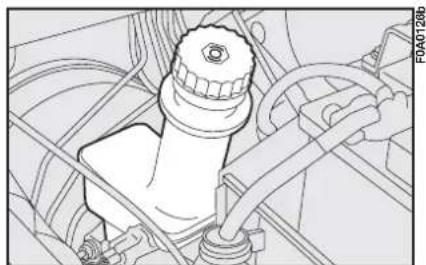
natural_image
Technical line drawing of a mechanical assembly with no visible text or symbolsfig. 14

Brake fluid is poisonous and very corrosive. In the event of accidental contact, wash the effected part with water and mild soap and rinse. If the fluid is swallowed, call a doctor immediately.

The symbol Ⓞ on the container indicates synthetic brake fluid distinguishing it from mineral fluid. Using mineral type fluid would damage the special rubber braking system gaskets beyond repair.
IMPORTANT Brake fluid is hygroscopic (meaning it absorbs humidity). This is why the fluid should be changed more frequently than shown in the service schedule if the vehicle is mainly driven in areas with a high percentage of humidity in the air.
POLLEN FILTER
The pollen filter is located under the dashboard near the central dashboard unit on passenger side.
If the vehicle is often used in dusty or extremely polluted environments, you should change the filter element more frequently than shown in the service schedule. It should be changed especially if the amount of air introduced into the passenger compartment is introduced.

natural_image
Technical line drawing of a mechanical assembly with hoses and components (no visible text or symbols)fig. 15
REPLACING THE FILTER fig. 16
Loosen the screws A, remove the cover and remove the filtering element to be replaced B.
AIR CLEANER
REPLACEMENT
Petrol versions
Loosen the screws on the side and on the air cleaner cover, remove the cover A-fig. 17 and remove the filtering element to be replaced.
1.9 Multijet versions
Loosen the three screws A-fig. 18 on the air cleaner cover, remove the cover B-fig. 19 and remove the filtering element C, to be replaced.
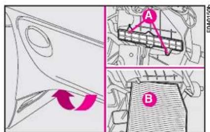
text_image
Technical diagram showing mechanical assembly with labeled parts A and B, including a rotation arrow indicating direction.fig. 16
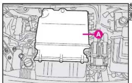
natural_image
Technical diagram of an engine compartment with a highlighted component (no text or symbols present)fig. 17
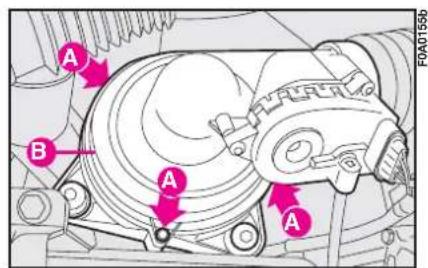
text_image
A B A A F0A0155bfig. 18
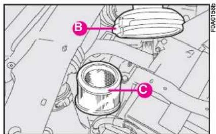
text_image
B C F0A0156bfig. 19
1.3 Multijet versions
Loosen the screws D-fig. 21, remove the cover E and remove the filtering element to be replaced.
BATTERY
The battery is of the "Limited maintenance" type: under normal conditions of use the electrolyte does not need topping up with distilled water.
CHECKING THE CHARGE
fig. 22
The battery charge may be checked satisfactorily through the inspection slot using the indicator and acting according to the colour the indicator shows.
Refer to the table below or to the plate (see figure) set on the battery.
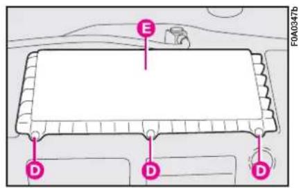
text_image
E D D D F0A0347bfig. 21
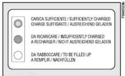
text_image
CARICA SUFFICIENTE / SUFFICIENTLY CHARGED CHARGE SUFFISANTE / AUSREICHEND GELADEN DA RICARICARE / INSUFFICIENTLY CHARGED A RECHARGER / NICHT AUSREICHEND GELADEN DA RABBOCCARE / TO BE FILLED UP A REMPLIR / NACHFÜLLENfig. 22
| Bright white | Top up electrolyte | Contact Fiat Dealership |
| Dark colour without green area in the centre | Low charge level | Charge the battery (Contact Fiat Dealership) |
| Dark colour with green area in the centre | Electrolyte level and charge sufficient | No action |

The liquid in the battery is poisonous and corrosive. Avoid contact with eyes and skin. Do not bring naked flames or possible sources of sparks near the battery: risk of fire and explosion.
CHANGING THE BATTERY
If required, replace the battery with a genuine spare part having the same specifications.
If a battery with different specifications is fitted, the service intervals given in the “Service schedule” in this section will no longer be valid. Refer therefore to the instructions provided by the battery manufacturer.

Incorrect fitting of electrical and electronic accessories can seriously use the vehicle.
If after buying the vehicle, you want to install electric accessories which require permanent electric supply (alarm, free-hand phone kit, etc.) contact Fiat Dealership whose qualified personnel, in addition to suggesting the most suitable devices, will evaluate the overall electric absorption, checking whether the vehicle electric system is capable of withstanding the load required, or whether it should be integrated with a more powerful battery.

Running the battery with low fluid level can damage the battery beyond repair and could also cause its explosion.

Batteries contain sub- stances that are very harmful for the environment. You are advised to have the battery changed at a Fiat Dealership. It is properly equipped for disposing of used batteries in an environmentally-friendly way that complies with the law.

If the vehicle is left inactive for long periods at cold, remove the battery more it in a warm place to get freezing.

When working on the battery or near it, always wear the
USEFUL ADVICE FOR LENGTHENING THE LIFE OF YOUR BATTERY
To avoid draining your battery and lengthen its life, observe the following indications:
- when you park the vehicle, ensure the doors, tailgate and bonnet are closed properly;
– the ceiling lights must be off. The vehicle is however provided with an automatic system for switching off internal lights;
- do not keep accessories (e.g. sound system, hazard lights, etc.) switched on for a long time when the engine is not running;
– before performing any operation on the electrical system, disconnect the battery negative cable;
– battery terminals shall always be perfectly tightened.
IMPORTANT A battery which is kept at a charge of less than 50% for any length of time will be damaged by sulphation leading to a reduction in cranking power and a higher risk of the battery electrolyte freezing (this may even occur at -10^ ).
If the vehicle is inactive for a long period of time, refer to the “Vehicle storage” paragraph in section “Driving your vehicle”.
If you want to add accessories after buying the vehicle (alarm system, free-hand phone kit, etc.) visit a Fiat Dealership. They can suggest the most suitable accessories to get and check whether the electric system can support the required load or whether a larger capacity battery is required.
These devices will, in fact, run off the battery even when the key is not inserted (vehicle parked) and can deploy the battery.
The total intake of these systems (factory and after-market) must be less than 0.6 mA x Ah (of the battery) as shown in the following table:
| Battery Maximum | |
| admitted stand-by intake | |
| 40 Ah 24 mA | |
| 50 Ah 30 mA | |
| 60 Ah 36 mA | |
ELECTRONIC CONTROL UNITS
When the vehicle is being used normally, special measures are not necessary.
The following instructions must be followed very carefully, however, if you work on the electrical system or in cases where emergency starting is necessary:
– Never disconnect the battery from the electrical system while the engine is running.
- Disconnect the battery from the electrical system if you are recharging it. The modern battery chargers can discharge voltage up to 20V.
- Never perform emergency start-ups with a battery charger. Always use an auxiliary battery.
- Be particularly careful when connecting the battery to the electrical system. Ensure the battery posts are connected up to the right leads (the
polarity is correct) and check that the connection has been made properly.
- Do not connect or disconnect the terminals of the electronic units while the ignition key is at MAR.
- Do not check polarity through sparking.
- Disconnect the electronic units if you are electrically welding the vehicle body. Remove the units if temperatures exceed 80^ (special operations on the bodywork, etc.).
IMPORTANT If the sound system or alarm systems are not installed correctly, they can interfere with the working of the electronic control units.

Modifications or repairs to the electrical system carried out incorrectly and without bearing the features of the system in mind can cause malfunctions with the risk of fire.
WHEELS AND TYRES
TYRE PRESSURE
Check the pressure of each tyre, including the spare, every two weeks and before long journeys.
The pressure must be checked when the tyre is rested and cold.
It is normal for the pressure to rise when you are driving. If you have to check or restore the pressure when the tyres are warm, remember that the pressure value must be 0.3 bar above the specified value.
See “Wheels” in “Technical specifications” for the correct tyre inflation pressure.

Tyre pressure must be correct to ensure good road holding.
Incorrect pressure causes abnormal tyre wear fig. 22:
A - Correct pressure: tyre wears evenly
B - Under inflated tyre: shoulder tread wear
C - Over inflated tyre: centre tread wear.
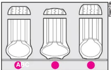
text_image
ABC F0A0173bfig. 22

If the pressure is too low the tyre overheats and this can cause it serious e.
Tyres must be replaced when the tread wears down to 1.6 mm. In any case, comply with the laws in the country where the vehicle is being driven.
IMPORTANT NOTES
As far as possible avoid sharp braking and screech starts.
Be careful not to hit the kerb, pot-holes or other obstacles hard. Driving for long stretches over bumpy roads can damage the tyres.
Periodically check that the tyres have no cuts in the sidewalls, abnormal swelling or irregular tyre wear. If any of these occur, have the vehicle seen to at a Fiat Dealership.
Avoid overloading your vehicle: this can seriously damage wheels and tyres.
If you get a flat tyre, stop immediately and change it so as not to damage the tyre, the wheel, the suspension and the steering.
Tyres age even if they are not used very much. Cracking of the tread rubber and the side walls are a sign of this ageing. In any case, if the tyres have been fitted for more than six years they should be examined by an expert who can judge whether they are still fit for use. Remember to check the spare tyre particularly carefully too.
If a replacement is necessary, always use new tyres and avoid using ones the origin of which you are not certain about.
The Fiat Doblò fits tubeless tyres. Under no circumstances use an inner tube with these tyres.
If you replace a tyre it is a good idea to change the inflation valve, too.
To ensure the front and rear tyres all wear evenly, you are advised to change the tyres over every 10-15 thousand kilometres keeping them on the same side of the vehicle so as not to reverse the direction of rotation.

Do not change the tyres over in criss-cross fashion by moving a tyre from the
left hand side of the vehicle to the right and vice versa.
RUBBER TUBING
Follow the “Service Schedule” to the letter as concerns braking and fuel line rubber tubing. Ozone, high temperatures and long absence of fluid in the system can in fact cause the hardening and cracking of the pipes with possible loss of fluid. A careful check is therefore essential.
WINDSCREEN/ REAR WINDOW WIPERS
BLADES
Periodically clean the rubber part using special products; TUTELA PROFESSIONAL SC 35 is recommended.
If the rubber blades are bent or worn they should be replaced. In any case they should be changed once a year.
A few simple notions can reduce the possibility of damage to the blades:
- If the temperature falls to below zero, make sure the rubber blade is not frozen to the windscreen. If necessary, free it with a de-icing compound.
- Remove any snow that has settled on the glass: besides saving the blades you will avoid straining the electric windscreen wiper motor and causing it to overheat.
- Do not operate the windscreen or rear window wipers on dry glass.

Driving with worn wiper blades is a serious hazard, because visibility is re-in bad weather.
Changing the windscreen wiper blade
1) Lift the windscreen wiper arm A-fig. 23 off the glass and position the blade so as to form a right angle with the arm.
2) Press tab B on the retainer and remove the blade to be replaced from arm A.
3) Fit the new blade by inserting the tab into the special slot in the arm. Make sure it is properly locked into place.
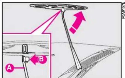
text_image
A B F0A0157bfig. 23
Changing the rear window wiper blade
I) Lift the cover A-fig. 24 and fig. 25 and dismantle the arm from the vehicle by unscrewing the nut B which holds it onto the knuckle.
2) Position the new arm correctly and fasten the nut.
3) Lower the cover.
SPRAY NOZZLES
If there is no jet of liquid, first make sure that there is liquid in the reservoir: see "Checking fluid levels" in this section.
Then make sure that the holes in the nozzles are not clogged up. Use a pin for this if necessary.
The windscreen washer jets fig. 26 can be directed by adjusting the inclination of the nozzles. Direct the spray so that it reaches the highest point reached by the blades.
The rear window washer jet fig. 27 can be directed by adjusting the direction of the nozzles.

text_image
FOA0160bfig. 26
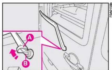
text_image
A B FOA0158bfig. 24
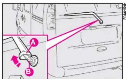
text_image
A B FOA0159bfig. 25
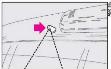
text_image
FA040161bfig. 27
BODYWORK
PROTECTION FROM ATMOSPHERIC AGENTS
The main causes of rust are:
– atmospheric pollution
– salt and humidity in the atmosphere (coastal or very hot and humid areas)
– environmental conditions that are specific to the season.
Not to be underestimated is also the abrasive action of wind-borne atmospheric dust and sand and mud and gravel raised by other vehicles.
For your Fiat Doblò, Fiat has used leading-edge technological solutions to effectively protect the body from rust.
These include:
– Painting systems and products that make the vehicle particularly resistant to rust and scratching.
– The use of zinc-plated sheet steel which is highly resistant to rust.
- The spraying of the underbody, engine compartment, inside the wheelhouses and other parts with wax-based products with a high protective capacity.
- Spraying plastic-coating materials to protect the most exposed points: under the door, inside the wings, the edges etc.
- The use of "open" box sections to prevent condensation and water from building up and rusting the inside of the parts.
BODY AND UNDERBODY WARRANTY
Your Fiat Doblò is covered by warranty against any original structural or body part being perforated by rust. Refer to the Warranty Booklet for the general terms.
ADVICE FOR PRESERVING THE BODYWORK
Paint
Paintwork does not only serve an aesthetic purpose, but also protects the underlying sheet metal.
In the case of deep scrapes or scores, you are advised to have the necessary touching up carried out immediately to avoid the formation of rust.
Only use genuine products when touching up the paintwork (see "Bodywork paint identification plate" in section "Technical specifications").
Ordinary maintenance of the paint-work means washing it. The frequency you should do this depends on the conditions and the environment the vehicle is driven in. For example, in areas with a high level of air pollution or on roads sprinkled with road salt, wash the vehicle more frequently.

Detergents pollute water. For this reason, the vehicle must be washed in an area equipped for the collection and purification of the liquids used while washing.
To wash the vehicle properly:
I) Remove the aerial from the roof to prevent damaging it when washing the vehicle in an automatic carwash.
2) Wash the body using a low pressure jet of water.
3) Wipe a sponge with a slightly soapy solution over the bodywork, frequently rinsing the sponge.
4) Rinse well with water and dry with a jet of air or a chamois leather.
When drying the vehicle, be careful to get at those parts which are not so easily seen e.g. the door frames, bonnet and around the headlights where water can most readily collect. You should leave the vehicle out in the open so that any water remaining can evaporate more easily.
Do not wash the vehicle after it has been parked in the sun or while the bonnet is hot: it could take the shine off the paint.
Outside plastic parts must be cleaned following the usual vehicle washing procedure.
Where possible avoid parking the vehicle under trees; the resinous substances that certain species of tree shed dull the paintwork and increase the possibility of rust forming.
IMPORTANT Bird droppings must be washed off immediately and with great care as their acid is particularly aggressive.
Windows
Use specific window cleaner products to clean cloths to avoid scratching the glass or damaging the transparency.
IMPORTANT To prevent damage to the electric heater element, wipe the inside of the heated rear window gently in the same direction as the elements.
Engine compartment
At the end of each winter season, carefully clean the engine compartment. Be careful not to direct the jet of water on the electronic control units. Have this done at a garage.

Detergents pollute water. The vehicle must therefore be washed in an area equipped for the collection and purification of the liquids used while washing.
IMPORTANT The engine compartment should be washed while the engine is cold and with the ignition key at STOP. After washing, make sure that the various protections (e.g. rubber boots and various guards) have not been removed or damaged.
INTERIORS
From time to time check that water has not collected under the mats (from dripping shoes, umbrellas etc.) which could cause the steel to rust.

Never use inflammable products such as petroleum ether or petrol to clean inside the vehicle. The electrostatic charges that are generated while rubbing to clean could become a fire risk.
CLEANING SEATS AND FABRICS
- Remove dust with a soft brush and vacuum cleaner.
- Brush the seats with a damp sponge with water and a neutral soap.
Use appropriate products designed to preserve the appearance of components.
IMPORTANT Do not use alcohol or petrol to clean the instrument panel.

Do not keep aerosol cans in the vehicle. There is the risk they might explode. Aerosol cans must never be exposed to a temperature above 50^ C; when the weather starts to get hot the temperature inside the vehicle might go well beyond that figure.
STEERING WHEEL / GEAR LEVER KNOB WITH GENUINE LEATHER COVERING
These components shall only be cleaned with water and neutral soap. Never use spirit or alcohol-based products.
Before using special products for cleaning interiors, read carefully label instructions and indications to make sure they are free from spirit and/or alcohol-based substances.
If when cleaning the windscreen with special glass products, some drops fall on the leather covering of the steering wheel/gear lever knob remove them immediately and then clean with water and neutral soap.
IMPORTANT Take the utmost care when engaging the steering lock to prevent scratching the leather covering.
TECHNICAL SPECIFICATIONS
VEHICLE IDENTIFICATION DATA CHASSIS MARKING
fig. 1
It is printed on the passenger compartment floor, near the right-hand front seat.
It can be reached by lifting the special flap in the carpeting and includes the following data:
- vehicle model ZFA 223000;
- chassis number.
ENGINE MARKING
The marking is stamped on the cylinder block and includes the model and the serial number.
MODEL PLATE
The plate A-fig. 2-3, is applied to the front engine crossmember.
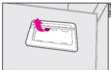
natural_image
3D diagram of a rectangular tray with a pink arrow indicating direction, no text or symbols presentfig. I
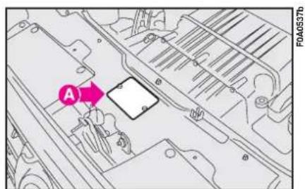
text_image
A F0A0537bfig. 2 - 1.4 8V versions

text_image
A FOA0538bfig. 3 - Multijet versions
The plate fig. 4bears the following identification data:
B - Homologation number
C - Vehicle type code
D - Chassis number
E - Maximum vehicle weight fully loaded
F - Maximum vehicle weight fully loaded with trailer.
G - Maximum vehicle weight on front axle.
H - Maximum vehicle weight on rear axle
I - Engine type
L - Body version code
M - Spare part code
M - Smoke opacity index (for diesel engines).
BODYWORK PAINT IDENTIFICATION PLATE
The plate fig. 5 is applied inside the bonnet.
It bears the following data:
A - Paint manufacturer
B - Colour name
C - Fiat colour code
D - Respray and touch up code.
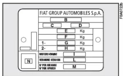
text_image
FIAT GROUP AUTOMOBILES S.p.A. B C D E Kg F Kg 1- G Kg 2- H Kg N MOTORE-ENGINE I VERANONE VERSION L N° PER ECKAMBI N° PER SPARES M F0A0722bfig. 4
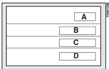
flowchart
graph TD
    A["A"] --> B["B"]
    B --> C["C"]
    C --> D["D"]
fig. 5
| Engine Engine | code |
| 1.4 8V 350A1000 | |
| Versions Bodywork | version code |
| Cargo 223ZXPIAAX | |
| Cargo high roof 223ZXPIABX | |
| Cargo extra capacity 223WXPIAAX | |
| Cargo high roof - extra capacity 223WXPIABX | |
| Cargo small capacity 223ZXPIAAY | |
| Cargo high roof - small capacity 223ZXPIABY | |
| Cargo Maxi (long wheelbase) 223WXPIAAXL | |
| Cargo Maxi (long wheelbase) - small capacity 223WXPIAAYL | |
| 5 seater combi NI 223WXPIAAZ | |
| Panorama 223AXPIA10 | |
| Panorama high roof 223AXPIA10B | |
| 7 seater family 223AXPIA10C |
HOMOLOGATION FOR SPECIFIC MARKETS
| Engine Engine | code |
| 1.4 8V 350A1000 | |
| Versioni Bodywork | version code |
| Cargo | 223ZXPIAXX |
| Cargo high roof | 223ZXPIAXY |
| Cargo extra capacity | 223WXPIAXX |
| Cargo high roof - extra capacity | 223WXPIAXY |
| Cargo Maxi (long wheelbase) | 223WXPIAXXL |
| 5 seater combi NI 223WXPIAXZ | |
| Panorama | 223AXPIAXX |
| Panorama high roof | 223AXPIAXXB |
| 7 seater family | 223AXPIAXXC |
EUROPEAN HOMOLOGATION
| Engine Engine | code |
| 1.3 Multijet 199 A 2000 | |
| Versions Bodywork | version code |
| Cargo 223ZXNIAAX | |
| Cargo high roof 223ZXNIABX | |
| Cargo extra capacity 223WXNIAAX | |
| Cargo high roof - extra capacity 223WXNIABX | |
| Cargo small capacity 223ZXNIAAY | |
| Cargo high roof - small capacity 223ZXNIABY | |
| Cargo Maxi (long wheelbase) 223WXNIAAXL | |
| Cargo Maxi (long wheelbase) - small capacity 223WXNIAAYL | |
| 5 seater combi NI 223WXNIAAZ |
| Engine Engine | code |
| 1.3 Multijet 85 HP 223 A 9000 | |
| Versions Bodywork | version code |
| Cargo 223ZXMIAAX | |
| Cargo high roof 223ZXMIABX | |
| 5 seater combi NI 223ZXMIAAZ | |
| Panorama 223AXMIA08D | |
| Panorama high roof 223AXMIA08B | |
| 7 seater family | 223AXMIA08E |
HOMOLOGATION FOR SPECIFIC MARKETS
| Engine Engine | code |
| 1.3 Multijet 199 A 2000 | |
| Versions Bodywork | version code |
| Cargo | 223ZXNIAXX |
| Cargo high roof 223ZXNIAXY | |
| Cargo extra capacity | 223WXNIAXX |
| Cargo high roof - extra capacity 223WXNIAXY | |
| Cargo Maxi (long wheelbase) | 223WXNIAXXL |
| 5 seater combi NI | 223WXNIAXZ |
EUROPEAN HOMOLOGATION
| Engine Engine | code |
| 1.9 Multijet 105 HP 223 B 1000 | |
| Versions Bodywork | version code |
| Cargo 223ZXLIAAX | |
| Cargo high roof 223ZXLIABX | |
| Cargo extra capacity 223WXLIAAX | |
| Cargo high roof - extra capacity 223WXLIABX | |
| Cargo small capacity 223ZXLIAAY | |
| Cargo high roof - small capacity 223ZXLIABY | |
| Cargo Maxi (long wheelbase) 223WXLIAAXL | |
| Cargo Maxi (long wheelbase) - small capacity 223WXLIAAYL | |
| 5 seater combi NI 223WXLIAAZ | |
| Panorama 223AXLIAA07 | |
| Engine Engine | code |
| 1.9 Multijet 100 HP 223 B 2000 | |
| Versions Bodywork | version code |
| Cargo 223ZXRIAAX | |
| Cargo high roof 223ZXRIABX | |
| Cargo extra capacity 223WXRIAAX | |
| Cargo high roof - extra capacity | 223WXRIABX |
| Cargo Maxi (long wheelbase) | 223WXRIAAXL |
HOMOLOGATION FOR SPECIFIC MARKETS
| Engine Engine | code |
| 1.9 Multijet 105 HP 223 B 1000 | |
| Versions Bodywork | version code |
| Cargo | 223ZXLIAXX |
| Cargo high roof 223ZXLIAXY | |
| Cargo extra capacity 223WXLIAXX | |
| Cargo high roof - extra capacity | 223WXLIAXY |
| Cargo Maxi (long wheelbase) | 223WXLIAXXL |
| 5 seater combi NI | 223WXLIAXZ |
| Panorama | 223AXLIAXX |
EUROPEAN HOMOLOGATION
| Engine Engine | code |
| 1.9 Multijet 120 HP 186 A 9000 | |
| Versions Bodywork | version code |
| Cargo 223ZXHIAAX | |
| Cargo high roof 223ZXHIABX | |
| Cargo Maxi (long wheelbase) 223ZXHIAAXL | |
| 5 seater combi NI 223ZXHIAAZ | |
| Panorama 223AXHIA06 | |
| Panorama high roof 223AXHIA06B | |
| 7 seater family 223AXHIA06C |
ENGINE
| GENERAL FEATURES 1.4 8v | ||
| Type code 350A1000 | ||
| Cycle Otto | ||
| Number and layout of cylinders 4 in line | ||
| Piston bore and stroke mm | 72,0 x 84 | |
| Total displacement | cm^3 | 1368 |
| Compression ratio 11,1 : 1 | ||
| Max power (CEE): | ||
| kW | 57 | |
| HP | 77 | |
| corresponding ratio | rpm | 6000 |
| Max torque (CEE): | ||
| Nm | 115 | |
| kgm | 11,7 | |
| corresponding ratio | giri/min | 3000 |
| Spark plugs | NGK | ZKR7A - 10 |
| Fuel | Unleaded petrol95 RON | |
| GENERAL FEATURES | 1.3 Multijet 75 HP | 1.3 Multijet 85 HP | 1.9 Multijet 100 HP* | 1.9 Multijet 105 HP | 1.9 Multijet 120 HP | |
| Type code | 199 A2 000 | 223 A9 000 | 223 B2 000 | 223 B1 000 | 186 A9 000 | |
| Cycle | Diesel | Diesel | Diesel | Diesel | Diesel | |
| Number and layout of cylinders | 4 in line | 4 in line | 4 in line | 4 in line | 4 in line | |
| Piston bore and stroke mm | 69.6x 82 | 69.6x 82 | 82.0 x 90,4 | 82.0 x 90,4 | 82.0 x 90.4 | |
| Total displacement cm | ^3 | 1248 | 1248 | 1910 | 1910 | 1910 |
| Compression ratio | 17.6 : 1 | 17.6 : 1 | 18.0 : 1 | 18.0 : 1 | 18.0 : 1 | |
| Max power (EEC): | ||||||
| kW | 55 | 62 | 74 | 77 | 88 | |
| HP | 75 | 85 | 100 | 105 | 120 | |
| corresponding ratio rpm | 4000 | 4000 | 4000 | 4000 | 4000 | |
| Max torque (EEC): | ||||||
| Nm | 190 | 200 | 200 | 200 | 200 | |
| kgm | 19.4 | 20.4 | 20.4 | 20,4 | 20,4 | |
| corresponding ratio rpm | 1750 | 1750 | 1750 | 1750 | 1750 | |
| Fuel | Diesel fuel | Diesel fuel | Diesel fuel | Diesel fuel | Diesel fuel | |
(*) For specific markets where applicable
FUEL SUPPLY/IGNITION
Petrol versions
Electronic Multipoint sequential phased injection integrated with ignition, returnless system.
FUEL FEED/IGNITION
Multijet versions
"Common Rail" electronic control direct injection, turbo and intercooler.
SPARK PLUGS
The cleanness and soundness of the spark plugs are very important for keeping the engine efficient and polluting emissions down.
The appearance of the spark plug, if examined by an expert eyes, is a good way of pinpointing a problem even if it has nothing to do with the ignition system. Therefore, if the engine has problems, it is important to have the spark plugs checked at a Fiat Dealership.

Modifications or repairs to the fuel system that are not carried out prop-
erly or do not take the system technical specifications into account can cause malfunctions leading to the risk of fire.

The spark plugs must be changed at the times specified in the service
schedule. Only use the type of plugs indicated. If the heat ratio is less than required or the life specified is not guaranteed, problems can arise.
TRANSMISSION
CLUTCH
Hydraulic, self-adjusting external control.
GEARBOX
Five forward gears and reverse with synchromesh for front gear engagement.
Cyclical gear reduction and differential assembly incorporated in the gearbox.
Drive transmission to the front wheels by means of drive shafts connected to the differential assembly and the wheels with CV joints.
BRAKES
SERVICE AND EMERGENCY BRAKES
Front:
– disc, floating shoe, self-ventilated.
Rear:
– drum, self-centring callipers.
Crossed hydraulic circuit control.
Vacuum brake booster.
ABS system with four sensors and EBD.
Automatic take-up of friction liner wear.
Lacking the ABS, there is the brake force distributor that acts on rear brake circuit according to load on rear axle
HANDBRAKE
Controlled by a lever, it works mechanically on the rear brake shoes.
SUSPENSIONS
FRONT
Independent wheel, McPherson suspension with steel wishbones anchored to an auxiliary crossmember.
Coil springs and sway bar.
Double acting telescopic hydraulic shock absorbers.
REAR
Stiff axle with wishbones.
Double acting telescopic hydraulic shock absorbers.
Sway bar in Fiat Doblò Passengers Transport versions.
STEERING
Energy-absorbing jointed steering wheel.
Permanently lubricated rack and pinion.
Permanent lubrication joints.
Minimum steering circle: 10.5 metres (average between versions); 11.8 m for Long wheelbase versions,
STRUCTURE
Self-supporting chassis, three or five doors, high-resistance, multiple thickness structural elements for progressive energy absorption in impacts.
Side bars in doors for side impact protection and stiffening the passenger compartment in the event of front impacts.
The front and rear ends of the underbody crumple to reduce repair costs following low speed impacts.
WHEELS
RIMS AND TYRES
High resistance printed steel rims of alloy rims.
Tubeless tyres with radial carcass.
The homologated tyres are listed in the log book.
IMPORTANT In the event of discrepancies between the information provided in this Owner Handbook and the Log Book, consider the specifications shown in the Log Book only.
To ensure safety of the vehicle in movement, it must be fitted with tyres of specified size and of the same make and type on all wheels.
IMPORTANT Do not use inner tubes with tubeless tyres.
Do not fasten alloy wheels with the steel wheel bolts and vice versa. For details on the compatibility between rims and bolts, see "If a tyre is punctured" in section "In an emergency".
SPARE WHEEL
Pressed steel rim.
Tubeless tyre.
SNOW CHAINS
Only use low profile chains, see "Snow chains".
WHEEL GEOMETRY
Front wheel toe-in measured from rim to rim: 0 ± 1 mm.
The values refer to the vehicle in running order.
UNDERSTANDING TYRE MARKING
The following are the necessary indications to understand the meaning of the markings on the tyre.
Example: 185/65 R 15 88 T
185 = Nominal width (S, distance between sidewalls in mm).
65 = Height/width ratio (H/S, as a percentage).
R = Radial tyre.
15 = Rim nominal diameter in inches (∅).
88 = Load rating.
T = Maximum speed rating.
Maximum speed rating
Q = up to 160 km/h.
R = up to 170 km/h.
S = up to 180 km/h.
T = up to 190 km/h.
U = up to 200 km/h.
H = up to 210 km/h.
V = up to 240 km/h .
Maximum speed rating for snow tyres
Q M+S = up to 160 km/h
T M+S = up to 190 km/h
H M+S = up to 240 km/h
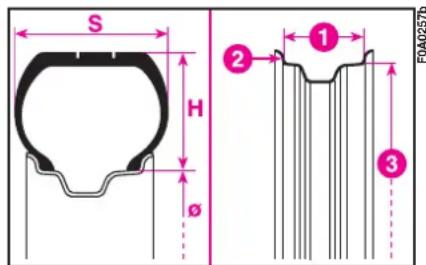
text_image
S H Ø ① ② ③ F0A0257bfig. 6
UNDERSTANDING RIM MARKINGS
The following are the necessary indications to understand the meaning of the markings on the rim.
Example: 5^1/_2J × 15 H2
5^1/_2 = rim width in inches (I)
J = rim drop centre outline (side projection where the tyre bead rests) (2)
15 = rim nominal diameter in inches (corresponds to diameter of the tyre to be mounted) (3 = ∅)
H2 = "hump" shape and number (relief on the circumference holding the tubeless tyre bead on the rim)
| Versions | Steel rim | Alloy rim | Factory-fitted tyre | Alternative min. sizes that can be adopted (**) | Tyre (*) | Space-saver spare wheel |
| Passenger Transportation | 5,5 J x 15H2-ET32 | 5,5 J x 15H2-ET32 | 185/65 R15 88T | 185/65 R15 88T | 185/65 R15 88Q (M+S) | 125/80 R15 95M |
| Family (7 seater) | 5,5 J x 15H2-ET32 | 5,5 J x 15H2-ET32 | 185/65 R15 92T | 185/65 R15 88T | 185/65 R15 88Q (M+S) | - |
| Cargo standard capacity/Combi N1 | 5,5 J x 15H2-ET32 | 5,5 J x 15H2-ET32 | 185/65 R15 92T(or EXTRA LOAD or Reinforced) | 175/75 R14 C99/98T175/70 R14 C95/93T | 185/65 R15 92Q (M+S) | - |
| Cargo extra capacity/Long wheelbase/Combi N1 (where fitted) | 5,5 J x 14H2-ET32 | 5,5 J x 14H2-ET32 | 175/75 R14 C99/98T | 175/75 R14 95S175/70 R14 95S | 175/75 R14 C99/98 Q (M+S) | - |
| Passenger Transportation Natural Power | 5,5 J x 14H2-ET32 | 5,5 J x 14H2-ET32 | 175/70 R14 C95/93S | 175/70 R14 88T | 175/70 R14 88 Q (M+S) | - |
| Cargo Natural Power | 5,5 J x 14H2-ET32 | 5,5 J x 14H2-ET32 | 175/70 R14 C95/93S | - | - | - |
(*) Tyres with load and speed index equal to or higher than the specified values are admitted
(**) When replacing tyres, you are however recommended to adopt tyres with load and speed ratings equal to or higher than those of the factory-fitted tyres.
COLD INFLATION PRESSURES (bar)
Versions Size Medium load Full load
| Front Rear Frpnt Rear | |||||
| Passenger Transportation 185/65 R15 88T 2.3 (*) 2.3 (*) 2.3 2.7 | |||||
| Family (7 seater) 185/65 R15 92T 2.3 2.7 2.3 2.7 | |||||
| Cargo standard capacity/Combi N1 | 185/65 R15 92T | 2.3 | 2.7 | 2.3 | 2.7 |
| Cargo extra capacity/Long wheelbase 175/75 R14 C99/98T | 3.0 3.5 3.0 3.5 | ||||
| Combi NI extra capacity | 175/75 R14 C99/98T | 2.8 3.0 3.0 3.5 | |||
| Passenger Transportation Natural Power | 175/70 R14 C95/93S | 2.6 | 3.0 | 2.6 | 3.0 |
| Cargo Natural Power | 175/70 R14 C95/93S | 2.8 3.5 2.8 3.5 | |||
With warm tyres the pressure should be +0.3 bar in relation to the prescribed value. Check again the correct pressure when the tyres are cold.
(*) Up to 3 people + 50 kg.
PERFORMANCE
Top admitted speed after running-in, in km/h:
1.4 148
1.4 high roof 145
1.4 7 plae .... 145
1.3 Multijet 75 HP ...... 146
1.3 Multijet 85 HP ...... 153
I.3 Multijet 85 HP high roof .... 150
1.3 Multijet 85 HP 7 place .... 150
1.9 Multijet 100/105 HP ..... 168
1.9 Multijet 120 HP ...... 175
1.9 Multijet 120 HP high roof .... 172
1.9 Multijet 120 HP 7 place .. 172
DIMENSIONS
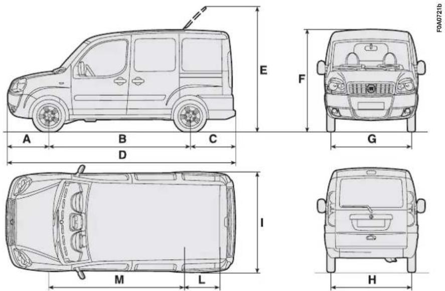
text_image
F0A0721b E F G A B C D I M L Hfig. 6
Dimensions are expressed in mm.
Height is intended on an unladen vehicle
Unladen boot volume (Fiat Doblò Cargo versions): 3,2 m ^4 .
Unladen boot volume (Fiat Doblò Passengers Transport versions):
- standard conditions 750~dm^3
- with rear table seat tilted 3000dm^3
| Dimensions Fiat | Dobliat Doblò Cargo Short wheelbase | Fiat Doblò Cargo Short wheelbase High roof | Fiat Doblò Cargo Long wheelbase | Fiat Doblò Passengers Transport | Fiat Doblò Passengers Transport High roof | Combi |
| A | 833 | 833 | 833 | 833 | 833 | 833 |
| B | 2583 | 2583 | 2963 | 2583 | 2583 | 2583 |
| C | 837 | 837 | 837 | 837 | 837 | 837 |
| D | 4253 | 4253 | 4633 | 4253 | 4253 | 4253 |
| E | 2345 | - | - | 2332 | - | 2332 |
| F (*) | 1831 | 2086 | 1817 | 1818 | 2073 | 1818 |
| G (*) | 1514 | 1514 | 1514 | 1514 | 1514 | 1514 |
| H | 1505 | 1505 | 1505 | 1505 | 1505 | 1505 |
| I | 1722 | 1722 | 1722 | 1722 | 1722 | 1722 |
| L | 454 | 454 | 454 | 454 | 454 | 454 |
| M | 2591 | 2591 | 2591 | 2591 | 2591 | 2591 |
(*) Minor differences in dimensions may occur according to rims and/or versions.
WEIGHTS
Weights (kg) - Fiat Doblò Cargo versions - Short wheelbase
| 1.48V | 1.375HP Multijet | 1.9100▼/105HP Multijet | 1.385HP Multijet | 1.9120HP Multijet | |
| Weight empty (including fluids, 90% fuel in the tank and no optional) | 1190 | 1270 | 1280 | 1290 | 1300 |
| Payload including driver (*): | 730 | 730 | 730 | 730 | 730 |
| Maximum admitted loads (**): | |||||
| – front axle: | 1010 | 1010 | 1010 | 1010 | 1010 |
| – rear axle: | 1150 | 1150 | 1150 | 1150 | 1150 |
| – total: | 1920 | 2000 | 2010 | 2020 | 2030 |
| Towable weight: | |||||
| – trailer with brakes | 1000 | 1200 | 1300 | 1300 | 1300 |
| – trailer without brakes | 500 | 500 | 500 | 500 | 500 |
| Maximum load on roof | 100 | 100 | 100 | 100 | 100 |
| Maximum load on ball coupling (trailer with brakes) | 60 | 60 | 60 | 60 | 60 |
(*) If special equipment is fitted (wing window, tow hitch, etc.), the unladen vehicle weight increases, thus reducing the specified payload.
(**) Loads not to be exceeded. The driver is responsible for arranging the loads so that they comply with these limits.
▼For specific markets, where applicable.
Weights (kg) - Fiat Doblò Cargo versions - Short wheelbase - Extra capacity
| 1.48V | 1.375HP Multijet | 1.9100▼/105HP Multijet | |
| Weight empty(including fluids, 90% fuel in the tank and no optional) | 1190 | 1270 | 1280 |
| Payload including driver (*): | 850 | 850 | 850 |
| Maximum admitted loads (**) | |||
| – front axle: | 1010 | 1010 | 1010 |
| – rear axle: | 1270 | 1270 | 1270 |
| – total: | 2040 | 2120 | 2130 |
| Towable weight: | |||
| – trailer with brakes | 1000 | 1200 | 1300 |
| – trailer without brakes | 500 | 500 | 500 |
| Maximum load on roof | 100 | 100 | 100 |
| Maximum load on ball coupling (trailer with brakes) | 60 | 60 | 60 |
(*) If special equipment is fitted (wing window, tow hitch, etc.), the unladen vehicle weight increases, thus reducing the specified payload.
(**) Loads not to be exceeded. The driver is responsible for arranging the loads so that they comply with these limits.
▼For specific markets, where applicable
Weights (kg) - Fiat Doblò Cargo versions - Short wheelbase - High roof
| 1.48V | 1.375HP Multijet | 1.9100▼/105HP Multijet | 1.385HP Multijet | 1.9120HP Multijet | |
| Weight empty (including fluids, 90% fuel in the tank and no optional) | 1210 | 1290 | 1300 | 1310 | 1320 |
| Payload including driver (*): | 730 | 730 | 730 | 710 | 710 |
| Maximum admitted loads (**)- front axle: | 1010 | 1010 | 1010 | 1010 | 1010 |
| - rear axle: | 1150 | 1150 | 1150 | 1150 | 1150 |
| - total: | 1940 | 2020 | 2030 | 2020 | 2030 |
| Towable weight:- trailer with brakes | 1000 | 1200 | 1300 | 1300 | 1300 |
| - trailer without brakes | 500 | 500 | 500 | 500 | 500 |
| Maximum load on roof | - | - | - | - | - |
| Maximum load on ball coupling (trailer with brakes) | 60 | 60 | 60 | 60 | 60 |
(*) If special equipment is fitted (wing window, tow hitch, etc.), the unladen vehicle weight increases, thus reducing the specified payload.
(**) Loads not to be exceeded. The driver is responsible for arranging the loads so that they comply with these limits.
* For specific markets, where applicable
Weights (kg) - Fiat Doblò Cargo versions - Short wheelbase - High roof - Extra capacity
| 1.48V | 1.375HP Multijet | 1.9100▼/105HP Multijet | |
| Weight empty(including fluids, 90% fuel in the tank and no optional) | 1210 | 1290 | 1300 |
| Payload including driver (*): | 850 | 850 | 850 |
| Maximum admitted loads (**) | |||
| – front axle: | 1010 | 1010 | 1010 |
| – rear axle: | 1270 | 1270 | 1270 |
| – total: | 2060 | 2140 | 2150 |
| Towable weight: | |||
| – trailer with brakes | 1000 | 1200 | 1300 |
| – trailer without brakes | 500 | 500 | 500 |
| Maximum load on roof | - | - | - |
| Maximum load on ball coupling (trailer with brakes) | 60 | 60 | 60 |
(*) If special equipment is fitted (wing window, tow hitch, etc.), the unladen vehicle weight increases, thus reducing the specified payload.
(**) Loads not to be exceeded. The driver is responsible for arranging the loads so that they comply with these limits.
▼For specific markets, where applicable
Weights (kg) - Fiat Doblò Cargo versions - Long wheelbase
| 1.48V | 1.375HP Multijet | 1.9100▼/105HP Multijet | 1.9120HP Multijet | |
| Weight empty (including fluids, 90% fuel in the tank and no optional) | 1240 | 1320 | 1330 | 1350 |
| Payload including driver (*): | 850 | 850 | 850 | 730 |
| Maximum admitted loads (**)- front axle: | 1010 | 1010 | 1010 | 1010 |
| - rear axle: | 1270 | 1270 | 1270 | 1150 |
| - total: | 2090 | 2170 | 2180 | 2080 |
| Towable weight:- trailer with brakes | 1000 | 1200 | 1300 | 1300 |
| - trailer without brakes | 500 | 500 | 500 | 500 |
| Maximum load on roof | 100 | 100 | 100 | 100 |
| Maximum load on ball coupling (trailer with brakes) | 60 | 60 | 60 | 60 |
(*) If special equipment is fitted (wing window, tow hitch, etc.), the unladen vehicle weight increases, thus reducing the specified payload.
(**) Loads not to be exceeded. The driver is responsible for arranging the loads so that they comply with these limits.
▼For specific markets, where applicable
Weights (kg) - Fiat Doblò Cargo versions - Short wheelbase - Small capacity (where provided)
| 1.48V | 1.375HP Multijet | 1.385HP Multijet | 1.9105HP Multijet | 1.9120HP Multijet | |
| Weight empty (including fluids, 90% fuel in the tank and no optional) | 1190 | 1270 | 1290 | 1280 | 1300 |
| Payload including driver (*): | 570 | 570 | 570 | 570 | 570 |
| Maximum admitted loads (**)- front axle: | 1010 | 1010 | 1010 | 1010 | 1010 |
| - rear axle: | 1150 | 1150 | 1150 | 1150 | 1150 |
| - total: | 1760 | 1840 | 1860 | 1850 | 1870 |
| Towable weight:- trailer with brakes | 1000 | 1200 | 1300 | 1300 | 1300 |
| - trailer without brakes | 500 | 500 | 500 | 500 | 500 |
| Maximum load on roof | 100 | 100 | 100 | 100 | 100 |
| Maximum load on ball coupling (trailer with brakes) | 60 | 60 | 60 | 60 | 60 |
(*) If special equipment is fitted (wing window, tow hitch, etc.), the unladen vehicle weight increases, thus reducing the specified payload.
(**) Loads not to be exceeded. The driver is responsible for arranging the loads so that they comply with these limits.
Weights (kg) - Fiat Doblò Cargo versions - Short wheelbase - High roof - Small capacity (where provided)
| 1.48V | 1.375HP Multijet | 1.385HP Multijet | 1.9105HP Multijet | 1.9120HP Multijet | |
| Weight empty (including fluids, 90% fuel in the tank and no optional) | 1210 | 1290 | 1310 | 1300 | 1320 |
| Payload including driver (*): | 570 | 570 | 570 | 570 | 570 |
| Maximum admitted loads (***) | |||||
| – front axle: | 1010 | 1010 | 1010 | 1010 | 1010 |
| – rear axle: | 1150 | 1150 | 1150 | 1150 | 1150 |
| – total: | 1780 | 1860 | 1880 | 1870 | 1890 |
| Towable weight: | |||||
| – trailer with brakes | 1000 | 1200 | 1300 | 1300 | 1300 |
| – trailer without brakes | 500 | 500 | 500 | 500 | 500 |
| Maximum load on roof | - | - | - | - | - |
| Maximum load on ball coupling (trailer with brakes) | 60 | 60 | 60 | 60 | 60 |
(*) If special equipment is fitted (wing window, tow hitch, etc.), the unladen vehicle weight increases, thus reducing the specified payload.
(**) Loads not to be exceeded. The driver is responsible for arranging the loads so that they comply with these limits.
Weights (kg) - Fiat Doblò Cargo versions - Long wheelbase - Small capacity (where provided)
| 1.48V | 1.375HP Multijet | 1.9105HP Multijet | 1.9120HP Multijet | |
| Weight empty (including fluids, 90% fuel in the tank and no optional) | 1240 | 1320 | 1330 | 1350 |
| Payload including driver (*): | 570 | 570 | 570 | 570 |
| Maximum allowed loads (**) | ||||
| – front axle: | 1010 | 1010 | 1010 | 1010 |
| – rear axle: | 1270 | 1270 | 1270 | 1150 |
| – total: | 1810 | 1890 | 1900 | 1920 |
| Towable weight: | ||||
| – trailer with brakes | 1000 | 1200 | 1300 | 1300 |
| – trailer without brakes | 500 | 500 | 500 | 500 |
| Maximum load on roof | 100 | 100 | 100 | 100 |
| Maximum load on ball coupling (trailer with brakes) | 60 | 60 | 60 | 60 |
(*) If special equipment is fitted (wing window, tow hitch, etc.), the unladen vehicle weight increases, thus reducing the specified payload.
(**) Loads not to be exceeded. The driver is responsible for arranging the loads so that they comply with these limits.
Weights (kg) - Fiat Doblò Passengers Transport versions
| 1.48V | 1.3 85HP Multijet | 1.9 105HP Multijet | 1.9 120 HP Multijet | |
| Weight empty (including fluids, 90% fuel in the tank and no optional) | 1230 | 1330 | 1320 | 1340 |
| Payload including driver (*): | 5p+225 | 5p+225 | 5p+225 | 5p+225 |
| Maximum allowed loads (**) | ||||
| - front axle: | 1010 | 1010 | 1010 | 1010 |
| - rear axle: | 1085 | 1085 | 1085 | 1085 |
| - total: | 1830 | 1930 | 1920 | 1940 |
| Towable weight: | ||||
| - trailer with brakes | 1000 | 1300 | 1300 | 1300 |
| - trailer without brakes | 500 | 500 | 500 | 500 |
| Maximum load on roof | 100 | 100 | 100 | 100 |
| Maximum load on ball coupling (trailer with brakes) | 60 | 60 | 60 | 60 |
(*) If special equipment is fitted (wing window, tow hitch, etc.), the unladen vehicle weight increases, thus reducing the specified payload.
(**) Loads not to be exceeded. The driver is responsible for arranging the loads so that they comply with these limits.
Weights (kg) - Fiat Doblò Passengers Transport versions - High roof
| 1.48V | 1.385HP Multijet | 1.9120HP Multijet | |
| Weight empty(including fluids, 90% fuel in the tank and no optional) | 1250 | 1350 | 1360 |
| Payload including driver (*): | 5p+225 | 5p+225 | 5p+225 |
| Maximum allowed loads (**) | |||
| – front axle: | 1010 | 1010 | 1010 |
| – rear axle: | 1085 | 1085 | 1085 |
| – total: | 1850 | 1950 | 1960 |
| Towable weight: | |||
| – trailer with brakes | 1000 | 1300 | 1300 |
| – trailer without brakes | 500 | 500 | 500 |
| Maximum load on roof | - | - | - |
| Maximum load on ball coupling (trailer with brakes) | 60 | 60 | 60 |
(*) If special equipment is fitted (wing window, tow hitch, etc.), the unladen vehicle weight increases, thus reducing the specified payload.
(**) Loads not to be exceeded. The driver is responsible for arranging the loads so that they comply with these limits.
Weights (kg) - Fiat Doblò Passengers Transport versions - 7-seat
| 1.48V | 1.375HP Multijet | 1.9120HP Multijet | |
| Weight empty(including fluids, 90% fuel in the tank and no optional) | 1320 | 1420 | 1430 |
| Payload including driver (*): | 7p+75 | 7p+75 | 7p+75 |
| Maximum allowed loads (**) | |||
| – front axle: | 1010 | 1010 | 1010 |
| – rear axle: | 1100 | 1100 | 1100 |
| – total: | 1920 | 2020 | 2030 |
| Towable weight: | |||
| – Towable weight | 1000 | 1300 | 1300 |
| – trailer without brakes | 500 | 500 | 500 |
| Maximum load on roof | - | - | - |
| Maximum load on ball coupling (trailer with brakes) | 60 | 60 | 60 |
(*) If special equipment is fitted (wing window, tow hitch, etc.), the unladen vehicle weight increases, thus reducing the specified payload.
(**) Loads not to be exceeded. The driver is responsible for arranging the loads so that they comply with these limits.
Weights (kg) - Fiat Doblò Combi versions N 1
| 1.48V | 1.375HP Multijet | 1.385HP Multijet | 1.9120HP Multijet | 1.9120HP Multijet | |
| Weight empty (including fluids, 90% fuel in the tank and no optional) | 1240 | 1320 | 1340 | 1330 | 1350 |
| Payload including driver (*): | 680 | 680 | 680 | 680 | 680 |
| Maximum allowed loads (**) | |||||
| – front axle: | 1010 | 1010 | 1010 | 1010 | 1010 |
| – front axle: | 1150 | 1150 | 1150 | 1150 | 1150 |
| – total: | 1920 | 2000 | 2020 | 2010 | 2030 |
| Towable weight: | |||||
| – trailer with brakes | 1000 | 1200 | 1300 | 1300 | 1300 |
| – trailer without brakes | 500 | 500 | 500 | 500 | 500 |
| Maximum load on roof | 100 | 100 | 100 | 100 | 100 |
| Maximum load on ball coupling (trailer with brakes) | 60 | 60 | 60 | 60 | 60 |
(*) If special equipment is fitted (wing window, tow hitch, etc.), the unladen vehicle weight increases, thus reducing the specified payload.
(**) Loads not to be exceeded. The driver is responsible for arranging the loads so that they comply with these limits.
CAPACITIES
| litres kg | 1.4 | Prescribed fuelRecommended products | |
| Fuel tank:including a reserve of: | 605 - 7 – | – | Unleaded petrol not lower than95 R.O.N |
| Engine cooling system: | 7 | – | 50 - 50 mixture of distilled waterand PARAFLU UP (▲) |
| Engine sump:Engine sump and filter: | 2.4 2.12.6 2.25 | SELENIA 20K (□) | |
| Manual gearbox: | 1.98 1.8 | TUTELA CAR ZC 75 SYNTH | |
| Power steering | 1.3 1.2 | TUTELA GI/E | |
| Front and rear brakes hydraulic circuit: | 0.5 – | TUTELA TOP 4 | |
| Hydraulic brake circuit with ABS: | 0.55 – | TUTELA TOP 4 | |
| Windscreen and rear window washer fluid reservoir: | 7 | – | Mixture of water and TUTELA PROFESSIONAL SC 35 |
(▲) For particularly hard climate conditions, we recommend use of a 60% PARAFLU UP and 40% demineralized water mixture.
(☐) For particularly cold temperatures use SELENIA MULTIPOWER.
| 1.3 Multijetlitres kg | 1.9 Multijetlitres kg | Prescribed fuelRecommended products | |||
| Fuel tank:including a reserve of: | 605 - 7 – | – | 605 - 7 – | – | Diesel fuel for motor vehicles(EN590 Specification) |
| Engine cooling system: | 6.5 – | 6.5 – | 50 - 50 mixture of distilled waterand PARAFLU UP (▲) | ||
| Engine sump:Engine sump and filter: | 3.0 (■) 2.6 (■)3.2 (■) 2.8 (■) | 4.0 (○) 3.5 (○)4.3 (○) 3.7 (○) | SELENIA TURBO DIESEL (○)SELENIA WR (■) | ||
| Manual gearbox: | 1.98 1.8 | 1.98 1.8 | TUTELA CAR ZC 75 SYNTH | ||
| Power steering | 1.3 1.2 | 1.3 1.2 | TUTELA GI/E | ||
| Front and rear brakes hydraulic circuit: | 0.5 – | 0.5 – | TUTELA TOP 4 | ||
| Hydraulic brake circuit with ABS: | 0.55 – | 0.55 – | TUTELA TOP 4 | ||
| Windscreen and rear window washer fluid reservoir: | 7 | – | 7 | – | Mixture of water and TUTELA PROFESSIONAL SC 35 |
(▲) For particularly hard climate conditions, we recommend use of a 60% PARAFLU UP and 40% demineralized water mixture. (○) For particularly cold temperatures use SELENIA WR.
FLUIDS AND LUBRICANTS
PRODUCTS WHICH MAY BE USED AND THEIR CHARACTERISTICS
| Specifications of the lubricants and fluids to use for best operation | Fluids and lubricants recommended | ApplicationsUse | |
| Lubricants for petrol engines (*) | Synthetic-based engine oils grade SAE 10W-40 that pass ACEA A3 and API SL specifications. | SELENIA 20K | [ATTIC]SAE 5W-40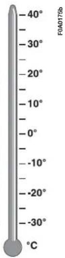 |
| Synthetic-based engine oils grade SAE 5W-30 that pass ACEA A1-A5 - API SL andFIAT 9.55535-MI specifications. | SELENIAMULTIPOWER | ||
| Lubricants for diesel engines (**) | Synthetic-based engine oils grade SAE 10W-40 that pass ACEA B3 and API CD specifications. | SELENIATURBO DIESEL | |
| Synthetic-based engine oils grade SAE 5W-40 that pass ACEA B4, API CF andFIAT 9.55535-M2 specifications. | SELENIAWR | ||
| Lubricants for diesel engines(1.3 Multijet versions) | Synthetic-based engine oils grade SAE 5W-40 that pass ACEA B4, API CF andFIAT 9.55535-M2 specifications |
SAE 5W-30 SAE 5W-40
(*) For very low temperatures, we recommend SELENIA MULTIPOWER.
(**) For very low temperatures, we recommend SELENIA WR.
| Use | Specifications of the lubricants and fluids to use for best vehicle operation | Fluids and lubricants recommended | Applications |
| Lubricants and greases for transmission | Oil SAE 75W-80 EP that passes API GL-5 and MIL-L-2105D LEV specifications | TUTELA CAR ZC 75 Synth | Mechanical gearbox and differentials |
| Oil type ATF DEXRON II D LEV, SAE 10 W | TUTELA GI/E | Hydraulic power steering | |
| Brake fluids | Synthetic fluid, FMVSS n° 116 DOT 4, ISO 4925, SAE J-1703, CUNA NC 956-01 | TUTELA TOP 4 | Hydraulic brakes and clutch controls |
| Radiator antifreeze | Red protective with antifreeze action, based on inhibited monoethylen glycol with organic formula based on O.A.T, That passes CUNA NC 956-16, ASTM D 3306 specifications | PARAFLU UP | Radiator antifreeze proportion: 50% distilled water and 50% PARAFLU UP (☐) |
| Diesel fuel additive | Diesel fuel additive | TUTELA DIESEL ART | To be mixed with diesel fuel (25 cm ^3 for 10 litres) |
| Windscreen/ rear window washer fluid | Mixture of alcohol and surfactants CUNA NC 956-II | TUTELA PROFESSIONAL SC 35 | To be used diluted or undiluted |
(*) IMPORTANT Do not top up or mix with fluids having characteristics different from those specified.
(☐) For particularly hard climate conditions, we recommend use of a 60% PARAFLU UP and 40% demineralized water mixture.
FUEL CONSUMPTION
The fuel consumption figures given in the table below are determined on the basis of the homologation tests set down by specific European Directives.
Consumption values are defined by means of the following procedures:
- urban cycle: consisting of a cold start and a simulated drive in city streets;
- extra-urban cycle: consisting in frequent accelerations, in all gears, simulating normal conditions of use. Speed ranges from 0 to 120km / h ;
– average combined cycle: consisting of 37% urban cycle and 63% extra-urban cycle.
IMPORTANT Road and traffic conditions, weather, driving style, fittings and accessories, load, roof racks, special devices and overall vehicle conditions can penalise aerodynamic penetration and in-
fluence fuel consumption rates which can be different from the values shown in the table (see "Cheap running that respects the environment").
Fuel consumption according to European Directive 2004/3/EC litres x 100 km)
| Urban Extra-urban Combined | |
| 1.4 9.2 6.3 7.4 | |
| 1.4 high roof 9.4 6.5 7.6 | |
| 1.4 7 seater 9.2 6.3 7.4 | |
| 1.3 Multijet 75 HP 6.5 4.7 5.4 | |
| 1.3 Multijet 85 HP 6.3 4.5 5.2 | |
| 1.3 Multijet 85 HP high roof 6.8 4.9 5.6 | |
| 1.3 Multijet 85 HP 7 seater 6.3 4.5 5.2 | |
| 1.9 Multijet 100/105 HP 7.5 4.8 5.8 | |
| 1.9 Multijet 120 HP 7.5 5.2 6.1 | |
| 1.9 Multijet 120 HP high roof 7.7 5.3 6.2 | |
| 1.9 Multijet 120 HP 7 seater 7.5 5.2 6.1 |
CO _2 EMISSION AT EXHAUST
The CO _2 emission levels at the exhaust given in the following table refer to combined consumption.
CO2 emissions according to Directive 1999/100/EC (g/km)
| 1.4 174 | |
| 1.4 high roof 178 | |
| 1.4 7 seater 174 | |
| 1.3 Multijet 75 HP 142 | |
| 1.3 Multijet 85 HP 137 | |
| 1.3 Multijet 85 HP high roof 148 | |
| 1.3 Multijet 85 HP 7 seater 137 | |
| 1.9 Multijet 100/105 HP 153 | |
| 1.9 Multijet 120 HP 160 | |
| 1.9 Multijet 120 HP high roof 163 | |
| 1.9 Multijet 120 HP 7 seater 160 |
RADIO-FREQUENCY REMOTE CONTROL: MINISTERIAL HOMOLOGATION
| International motoring code Country Homologation number | ||
| B Belgium RTT/D/X1924 | ||
| CH Switzerland BAKOM 99.0415 KP | ||
| D Germany TPS AI00282L CEPT LPD - D | ||
| DK Denmark CEPT SRD feDK | ||
| E Spain 01 00 0100 | ||
| F France 99 0346 PPL 0 | ||
| GB Great Britain | BPS037 | |
| GR | Greece | TA 232 |
| I | Italy | - |
| IRL | Ireland | TRA 24/5/ 107/11 |
| L | Luxembourg | 9942599-01 L2432/10562-01J |
| N | Norway | NO99000251 |
| P | Portugal | ICP-053TC-99 |
| S | Sweden | Ue990108 |
| SF Finland | FI99080046 | |
The homologation number is printed directly on the key grip for the markets where this is required.
PROVISIONS FOR THE PROCESSING OF A VEHICLE AT THE END OF ITS LIFE-CYCLE
For years now Fiat has been developing its global commitment towards the safeguarding and protection of the Environment through the continuous improvement of its production processes and the making of increasingly more “eco friendly” products. With a view to guaranteeing the best possible service to clients in full observance of environmental standards and in response to the obligations imposed by European Directive 2000/53/EC on end-of-life vehicles, Fiat offers its clients the possibility to hand in their vehicle* at the end of its life span without additional costs.
The European Directive, in fact, provides for the take-back of the vehicle without the last holder or owner of the same incurring expenses due to the fact that the market value of the vehicle is zero or negative. In particular, in almost all of the countries of the European Union, up until 1st January 2007, take-back of the vehicle free of charge only applies to vehicles registered from 1 July 2002 on, while, from 2007 on, take-back will be carried out free of charge, independently of the year of registration, provided that the vehicle still contains all its essential component parts (especially engine and body) and is free from additional waste materials.
Our contracted network of authorised treatment facilities has been carefully selected in order to provide a quality service to our customers by de-polluting and recycling “End of Life Vehicles” to approved environmental standards. To find out the location of your nearest authorised treatment facility, offering free of charge take-back, simply contact one of our dealers or refer to the Fiat web site or call the toll free number 00800 3428 0000.
INDEX
ABS 89
Accessories purchased by the owner 100
- installation of electric/electronic devices .... 100
- radio transmitters and cellular telephones...... 100
Air filter - replacement 162
Air recirculation 61
Air vents.... 58
Airbags (front and side) 91
- general warnings.... 94
- passenger airbag manual deactivation 93
Annual inspection schedule ..... 152
Ashtray - front .... 71
At the filling station 102
Battery - fluid level (electrolyte) ...... 163
- jump starting 144
- recharging 144
- replacing 164
Bodywork - maintenance .... 171
- version codes ...... 176
Bodywork paint plate.... 175
Bonnet 85
Boot - anchoring the load 84
- extending 80
- opening and closing 79
Boot light.... 134
Brake fluid level 160
Brake lights 134
Brakes - fluid level .... 160
- service and emergency ..... 181
Bulb (replacement) 130
- bulb types.... 131
- general instructions .... 130
Capacities 200
Catalytic converter (oxidising) 104
Catalytic converter (three way).... 104
Ceiling light.... 66 - control.... 67 - replacement.... 137
Cellular telephone setup ...... 99
Central side windows 72
Checking the levels.... 154
Child lock (device)....77
Cigar lighter 70
Clutch 182 - fluid level 160
CO_2 emissions at exhaust ..... 205
Containing running costs and pollution.... 110
Control buttons 68
Dashboard.... 21
Demisting - electric mirrors .... 61 - front side windows.... 60
- rear window.... 61
- windscreen 60
Digital clock 26-27
Dimensions 187
Direction indicators
- control 64
- front bulb replacement...... 133
- rear bulb replacement ..... 134
- side bulb replacement...... 134
Door lock/unlock
remote control 8
Double ladder (partitions) ..... 51
Driver's protection ladder (partitions).... 51
Driving your vehicle 106
EBD electronic brake force
distributor 90
Electric windows 74
Electronic brake force distributor EBD.... 90
Electronic control units 166
Engine
- fuel feed.... 181
- identification code ...... 176
- ignition 181
- specifications 179
Engine compartment
- washing.... 172
Engine coolant gauge 25
Engine coolant level.... 159
Engine oil
- checking the level...... 157
- consumption.... 158
- specifications 202
Engine oil level 157
EOBD system.... 97
Evaporation system.... 104
Exhaust gas recirculation...... 104
Extending the boot 80
Fiat CODE system.... 6
First aid kit.... 148
Follow me home 66
Front doors 74
Front foglights
- bulb replacement 133
- control button 68
Fuel
- at the filling station 102
- capacities 200
- fuel cut-off switch 69
- gauge 25
Fuel cap.... 103
Fuel consumption...... 204
Fuel cut-off switch.... 69
Fuses
- dashboard fusebox.... 139
- engine compartment fusebox 140
- replacement.... 138
- table.... 141
Gearbox
- gearbox use.... 109
- technical characteristics ..... 182
Getting to know your vehicle ... 6
Glove compartment 69
Handbrake.... 107-182
Hazard lights.... 68
Headlight beam corrector...... 88
Headlight slant (electrical corrector) 88
Headlights
- adjusting the headlights abroad....89
- beam corrector 88
- beam direction...... 89
- slant compensation.... 88
Head restraints
- front 54
- rear...... 54
Heated rear window 68
Heating.... 57
Hydraulic power steering
- fluid level 160
Identification data.... 174
If an accident occurs.... 147
- first aid kit.... 148
- if anyone is injured.... 148
Ignition switch.... 20
In an emergency 119
Individual settings 48
Instrument panel 22
Instruments.... 23
Interior equipment...... 69
Interiors.... 173
- cleaning seats and plastic parts...... 173
Jack....122
Jacking the vehicle.... 145
Keys......6
- duplicate copies.... 8
Lambda sensors.... 104
Levels
- checking.... 154
Loading ramps 87
Lubricants.... 202
Main beam headlights
- bulb replacement .... 131
- control 64
- flashing.... 64
Manual climate control system
- air distribution 59
- climatic comfort 62
- controls 61
- cooling 61
- maintenance 63
Model plate 174
Number plate light.... 136
Paint 171
Parking 107
Parking sensors.... 101
Partitions 51
- double ladder.... 51
- driver's protection ladder..... 51
- fixed panelled partition...... 50
- fixed partition with window . 51
Performance 186
Pollen filter 161
Power steering fluid level..... 160
Pretensioners 11
Prolonged vehicle inactivity ..... 117
Protecting the environment ..... 104
Radio transmitters .... 100
Radio-frequency
remote control 8
- battery replacement...... 9
- homologation numbers...... 206
Rear double doors.... 77
Rear foglight
- bulb replacement 134
- control button 68
Rear side windows.... 72
Rear window shelf 71
Rear window washer
- control 65
- fluid level 159
Rear window wiper
- blade.... 169
- control 65
- nozzle.... 170
- smart wash 66
Rearview mirrors
- electric.... 56
- exterior 55
- interior 55
Rev counter 24
Reversing light.... 134
Rims.... 183-185
Roof bars
- fasteners presetting 86
Rubber tubing.... 168
SBR system 10
Seat adjustment 48
Seat belts
- general warnings...... 13
- height adjustment...... 11
- maintenance 14
-use 9
Seats
- accessing the rear seat...... 52
- adjustments 48
- cleaning.... 173
- electrically heated 49
- passenger folding seat ...... 50
Side doors.... 75
Side/taillights
- control 63
- front bulb replacement...... 133
- rear bulb replacement ..... 134
Snow chains.... 116
Snow tyres 117
Sound system 97
- setup system 97
- sound system installation ..... 98
Spark plugs
- maintenance 181
- type.... 179
Starting the engine 105
- bump starting 121
- diesel versions ...... 107
- emergency startup ...... 107-119
- ignition switch.... 20
- jump starting 120
- petrol versions.... 106
- stopping the engine 108
- warming up the engine ..... 107
Steering column lock.... 20
Steering column stalks
- left-hand stalk 63
- right-hand stalk.... 64
Steering wheel adjustment...... 55
Steering.... 183
Stopping the engine 107
Storing the vehicle 118
Structure 183
Sun visors....71
Suspensions 182
Symbols...... 6
Tailgate....79
Technical characteristics ...... 174
Third brake lights 136
Tilting shelf 71
Tools 121
Top speed 186
Towing a trailer
- assembly diagram ...... 114
- tow hitch installation...... 114
- warnings ...... 113
Towing the vehicle.... 146
Transmission 182
Transporting children in safety. 15
Trip computer 36
Tyre pressure.... 185
Tyres
- if a tyre is punctured ..... 121
- inflation pressure 184
- reading.... 184
-standard.... 185
Using the gearbox 109
Vehicle maintenance.... 149
- additional checks.... 152
- annual inspection schedule ... 152
- scheduled service.... 149
- service schedule 150
Ventilation.... 57
Warning lights 39
Weights 188
Wheel
- replacement 122
- spare wheel 185
Wheel geometry 183
Wheel replacement 122
Windows (cleaning) 172
Windscreen and rear window wiper blades.... 169
Windscreen washer
- control 64
- fluid level 159
Windscreen wipers
- blades 169
- control 64
- nozzles.... 169
- smart wash 65
Windscreen/rear window washer fluid level 159
Wing window (adjustment) ..... 72
NOTES
SELÈNIA®
At the heart of your engine.
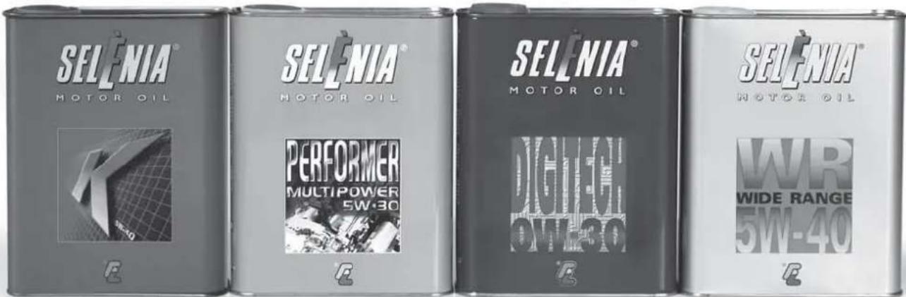
text_image
SELENIAMOTOR OIL SELENIAMOTOR OIL PERFORMERMULTIPOWER5W-30 SELENIAMOTOR OIL DICHLOW-30 SELENIAMOTOR OIL WRWIDE RANGE5W-40Always ask your mechanic for
SELÈNIA®
Oil change? The experts reccomend Selenia.
The engine of your car is factory filled with Selenia. This is an engine oil range which satisfies the most advanced international specifications. Its superior technical characteristics allow Selenia to guarantee the highest performance and protection of your engine.
The Selenia range includes a number of technologically advanced products:
SELENIA PERFORMER MULTIPOWER
Particularly ideal for the protection of new generation petrol engines, very effective even in the most severe weather conditions. It guarantees a reduction in fuel consumption (Energy conserving) and it is also ideal for alternative engines.
SELENIA K
is the synthetic lubricant with innovative technology, which ensures improved cold starting for petrol engines and the utmost protection also under typically "urban" conditions of use. Owing to its 5W-40 viscosimetric grade and its special formulation it more effectively meets the emission limits required by new European regulations and exceeds the major international specifications.
SELENIA WR
Oil specifically designed for common rail Multijet engines. Particularly effective during cold starts, it guarantees maximum wear protection and hydraulic tappets control, reduction in consumption and stability at high temperatures.
SELENIA DIGITECH
Fully synthetic lubricant for petrol and diesel engines. Its advanced technology guarantees maximum protection, a reduction in consumption and reliability in extreme climate conditions.
The range also includes Selenia StAR, Selenia Racing, Selenia 20K Alfa Romeo, Selenia TD, Selenia Performer 5W-40 For further information on Selenia products visit the web site www.flselenia.com.
COLD TYRE INFLATION PRESSURE (bar)
| Versions Size Medium load Full load | Front | Rear | Front | Rear | |
| Passenger Transportation | 185/65 R15 88T | 2.3 (*) | 2.3 (*) | 2.3 | 2.7 |
| Family (7 seater) | 185/65 R15 92T | 2.3 | 2.7 | 2.3 | 2.7 |
| Cargo standard capacity/Combi N1 | 185/65 R15 92T | 2.3 | 2.7 | 2.3 | 2.7 |
| Cargo extra capacity/Long wheelbase | 175/75 R14 C99/98T | 3.0 | 3.5 | 3.0 | 3.5 |
| Combi NI extra capacity | 175/75 R14 C99/98T | 2.8 | 3.0 | 3.0 | 3.5 |
| Passenger Transportation Natural Power | 175/70 R14 C95/93S | 2.6 | 3.0 | 2.6 | 3.0 |
| Cargo Natural Power | 175/70 R14 C95/93S | 2.8 | 3.5 | 2.8 | 3.5 |
With warm tyres the pressure should be +0.3 bar in relation to the prescribed value. Check again the correct pressure when the tyres are cold.
(*) Up to 3 people + 50 kg.
ENGINE OIL CHANGE
| 1.4 1.3 Multijet 1.9 Multijet | ||||
| litres kg l | tres kg litres kg | |||
| Oil sump 2.4 2.1 3.0 2.6 4.0 3.5 | ||||
| Oil sump and filter 2.6 2.25 3.2 2.8 4.3 3.7 | ||||
Dispose of waste oil properly
FUEL CAPACITY (litres)
| Tank capacity | 60 |
| Reserve | 5 - 7 |
| Use only unleaded petrol with a rated octane number (RON) not less than 95. Refuel diesel vehicles with diesel fuel for motor vehicles (EN590 Specification). | |

The data contained in this publication is intended merely as a guide. FIAT reserves the right to modify the models and versions described in this booklet at any time for technical and commercial reasons.
If you have any further questions please consult your FIAT dealer.
Printed in recycled paper without chlorine.