
TK 2400 ECO - Saw Güde - Free user manual and instructions
Find the device manual for free TK 2400 ECO Güde in PDF.


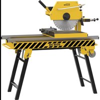
| Type | Mobile bench circular saw |
| Brand / Model | Güde TK 2400 ECO |
| Power supply | 230 V / 50 Hz / 1500 W (S6, 40%) |
| Motor speed (no load) | 5700 min-1 |
| Saw disc dimensions | 254 mm diameter, 30 mm bore, 24 teeth |
| Cutting depth at 90° | 75 mm |
| Cutting depth at 45° | 60 mm |
| Table size (without extension) | 446 x 640 mm |
| Table size (with extension) | 946 x 640 mm |
| Table height | 850 mm |
| Weight | 23 kg (approx.) |
| Sound pressure level (LpA) | 99.5 dB(A) |
| Sound power level (LWA) | 87.3 dB(A) |
| Suitable materials | Wood and soft plastics (lengthwise and crosswise cuts) |
| Features | Parallel stop with scale, mitre cut stop (adjustable 0-45°), sliding guide rod, bench extension (250 mm), dust exhaust connection, emergency switch, saw disc cover, splitting wedge |
| Safety equipment | Emergency stop switch, saw disc cover, splitting wedge, overload protection (thermal sensor), requires FI switch (fault current protection) |
| Maintenance | Clean dust from vents and moving parts after use; oil metal moving parts regularly; check screw tightness; replace saw disc when blunt |
| Accessories included | Legs (4), bench extension, parallel stop, mitre cut stop, sliding guide rod, exhaust hose, fixing material |
| Order number | 55166 |
Frequently Asked Questions - TK 2400 ECO Güde
User questions about TK 2400 ECO Güde
0 question about this device. Answer the ones you know or ask your own.
Ask a new question about this device
Download the instructions for your Saw in PDF format for free! Find your manual TK 2400 ECO - Güde and take your electronic device back in hand. On this page are published all the documents necessary for the use of your device. TK 2400 ECO by Güde.
USER MANUAL TK 2400 ECO Güde
natural_image
Icon of an open book inside a black circle (no text or symbols)English GB 18
Translation of original operating instructions
Circular saw bench
natural_image
Industrial machine with metal frame and black frame structure (no visible text or symbols)CE
Unit
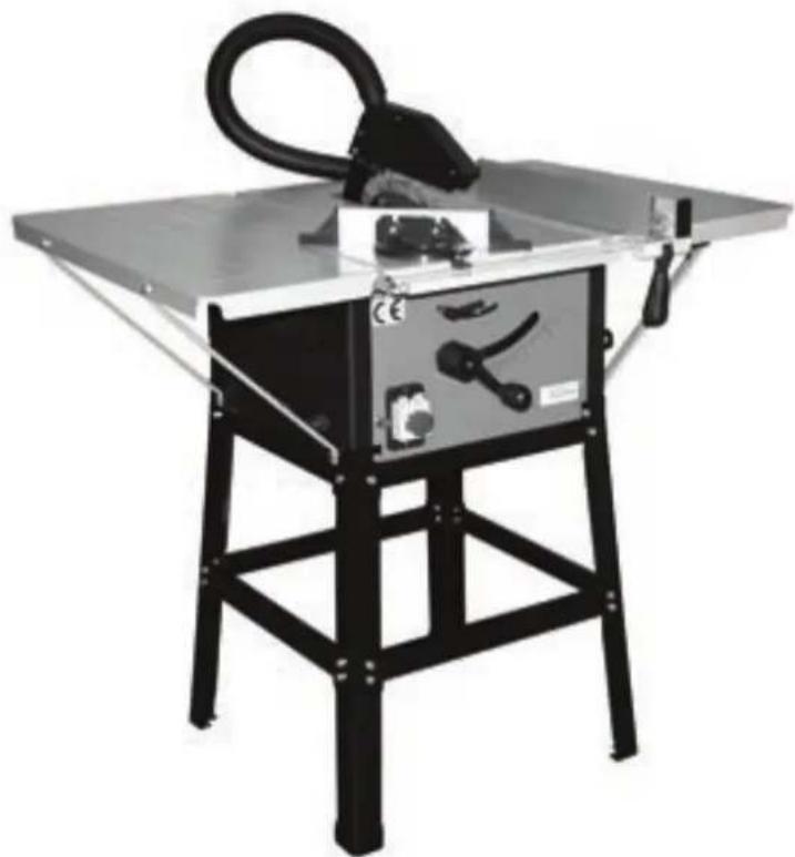
Mobile bench circular saw with a quality aluminium stop and a plastic mitre cut stop, height readjustment and mitre adjustment by a hand wheel.
Accessories (standard): table extension (removable 250 mm) of steel powder colour coated. Dust exhaust, saw disc of sintered metal, sliding guide rod, emergency switch, stop bar with millimetre scale, unit with base.
Appropriate accessories: spare saw disc (55163).
Scope of use: ideal for construction sites and indoor work.
Scope of Delivery
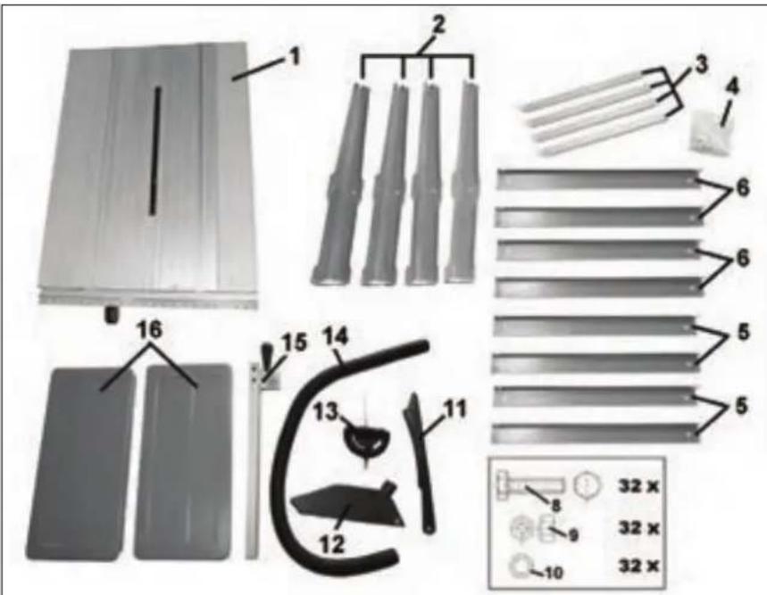
Fig. 1
- Saw bench
- Legs (4 pcs)
- Prop to attach the extension (4 pcs)
- Fixing/mounting material (8, 9, 10)
- Props (4 pcs)
- Props (4 pcs)
- Cup headed bolt (32 pcs)
- hexagon nut (32 pcs)
- Washer (32 pcs)
- Sliding guide bar
- Saw disc cover
- Mitre cut stop
- Exhaust hose
- Parallel stop
- Bench extension

Fig. 2
- Saw disc cover
- Saw disc
- Mitre cut stop
- Bench extension
- Bench extension prop
- Parallel stop clamping lever
- Scale
- Base
- Saw disc height readjustment
- Saw disc turning readjustment
- Emergency switch
- Turning readjustment lock lever
- Magnifying glass
- Mitre cut stop
- Exhaust hose
- Exhaust throat
- Cutting wedge
- Saw disc
- Sliding guide rod
Guarantee
The guarantee exclusively applies to material or manufacturing defects. The original proof of purchase with the purchase date must be submitted when lodging a claim in the guarantee period. The guarantee does not include any unauthorised use, e.g. appliance overloading, violent use, damage by a third party or foreign item. The failure to follow the Operating Instructions and assembly instructions and common wear and tear are not covered by the guarantee either.
General Safety Instructions
Prior to the initial use of the unit, the operating instructions should be read completely. If in doubt with regard to connection and operation of the unit, consult the manufacturer (servicing department).
FOLLOW THE INSTRUCTIONS BELOW CAREFULLY IN ORDER TO SECURE A HIGH DEGREE OF SAFETY:

Caution: Always operate with an FI (faulty current protection switch)!
Caution!
- Keep your workplace clean and tidy. Disorder at the worksite and bench increases the risk of accidents and injuries.
- Mind the conditions you work in. Never use electric tools in rainy weather. Never use the electric tools in moist and wet surroundings. Provide for good lighting. Do not use the electric tools in the proximity of flammable liquids and gases. Do not expose the electrical tools to rain or high air humidity.
- Do not let other persons access the unit. Visitors and watchers, children and sick or inform persons should be kept at a safe distance from your workplace.
- Provide for safe storage of the tools. The tools out of use should be stored at a dry elevated place and lock them not to be accessed by the others.
- Use the correct tool for corresponding job. For example, do not use small tools and accessories for the jobs that should be done by the big ones. Do not use the tools for purposes and works, which they have not been designed for. Keep your tools clean and sharp.
- Wear suitable clothing. Do not wear loose clothing or jewellery, they could be caught with moving parts. When working outdoors, rubber gloves and antiskid boots are recommended. If your hair is long, protective hairnet should be worn.
- Use personal protection equipment. Wear protective goggles and ear protectors. Wear a dustproof respirator. Always wear tight-fitting gloves when handling sharp edges and saw discs.
- Use a dust exhauster. If dust exhaust and collection of dust devices are available, the must be fitted on and used correctly. Make sure the dust and sawdust are taken away from you and the others standing near the unit.
- Look out for power cable. Do not pull the cable. Do not use it to unplug. Keep the cable away from the sources of heat, oil and sharp edges.
- Effect the safety of the piece to be worked. Use suitable clamps etc. It is always better and safer than to hold it with hand. In addition, you have both your hands free to work.
• Mind your balance and safe posture. Never lean over too far to the side when you are trying to reach something. - Remove any wrenches and spanners. All the wrenches and spanners used for replacing a tool, should be removed before switching off.
- Avoid any unintentional switching on. Before plugging the unit, remember to switch it off by the unit switch.
- When working outdoors, use special extension cables only. You need special extension cables for the use outdoors, they are fit to the purpose and marked appropriately.
- Be attentive at any time. Mind what you are doing. Use common sense at work. Do not use electrical tools when you feel tired.
- Look out for damaged parts. Check the unit through before use. Are any parts damaged? If the damage is slight only, consider if the operation of the unit will still be safe and perfect. Mind the correct adjustment and setting of moving parts. Do some elements fail to fit correctly in the others? Are some of them damaged? Is everything installed properly? Are any other conditions of the unit perfect functioning met? Any damaged protective devices etc. have to be repaired or replaced by authorised serviceman, unless otherwise stated in the operating manual. Have the defective switches replaced in an authorised workshop. Do not use the tool, if the switch cannot be put on and off as appropriate. Replace the bench inset, if worn. In an unlikely case that defects are found on the unit (protective devices and saw disc included), kindly consult a local servicing centre.
- Get protected from electric shock. Avoid any contact of the body with grounded parts, such as pipes, heating radiators, stoves, and refrigerators.
• Use approved parts only. Use identical spare parts only for maintenance and repairs. Consult an authorised servicing centre. - Warning! Use of accessories and additions other than expressly recommended in this manual may result in a risk for persons and property.
• Caution: Use a sliding guide bar at any work.

Before putting the saw in operation, make sure that no parts are damaged and no parts and protection devices are being. If they were, the saw should not be operated.
Emergency Action
Apply the first aid adequate to the injury and get qualified medical assistance as quickly as possible. Protect the injured person from more accidents and calm him/her down.
Signs on Unit
Meaning of Symbols
Symbols shown below are used throughout this manual and/or on the unit :
Product Safety
| CE | |||||
| Product compliance with respective EU standards |
Bans:
| General banIn combination withanother pictogram) | Do not touchrotating parts |
Warning:
| Warning/caution | Beware of hazardous electrical voltage |
Commands
| Use goggles Use | ear protectors | Read operating manual before use |
Environment Protection
| Wastes to be disposed of in a professional manner not to harm the environment. | Cardboard packaging to be collected for recycling. | Faulty and/or disposed of electrical/electronic appliances to be collected by authorised salvage places. |
Packaging:
| Protect from moisture | Keep Up Fragile |
Technical Data :
| ... | |||||
| Connection | Motor capacity | Speed | Acoustic output Sawlevel disc | Cutting depth 90° | |
| Cutting depth 45° | Table size | Table size (table extension) | Table height |
Assigned Use
Bench circular saw is fit to wood and soft plastics lengthwise and cross wise. Round materials (tubes, rounds etc.) are not allowed to be cut with the saw. Metal cutting is not permitted.
Residual Hazards and Protective Action
Mechanical Residual Hazards
| Hazard Description Protective action Residual hazards | |||
| Cutting, incision Risk of injury caused by rotating partsA contact with rotating band may cause severe injuries . | Be careful with small pieces to be worked. Always use a sliding guide bar included in the delivery .Never touch the saw band while it is moving | Worn or damaged aids should be replaced immediately | |
| Catching, winding Loose-fitting clothes, jewels or long hair may be caught by moving parts. | Wear tight-fitting garments and no jewels. Protect your hair with a hairnet . | ||
Electrical Residual Hazards
| Hazard Description Protective action Residual hazards | |||
| Direct electrical contact | Defective cable or plug may cause an electrical shock | Have the defective cable/plug exchanged by a professional. Use the unit only if connected via a faulty current switch (FI). Always unplug before any maintenance. Operate only with FI switch installed. | |
| Indirect electrical contact | |||
| Wounds cause by conductive parts on open electrical or defective structural parts. | |||
Noise Hazards
| Hazard Description Protective action Residual hazard | |||
| Impaired Hearing Prolonged work with the saw may result in hearing impairment | Always wear ear protectors | ||
Materials and Other Substances Hazards
| Hazard | Description | Protective | Action |
| Contact, aspiration Lungs may be affected by great amount of dust being formed. Health-hazardous sawdust emissions form operations without extracting the dust . | Always wear breathing mask when working with the unit. Install and use an exhaust equipment. |
Human Factors Neglect
| Hazard | Description | Protective | Action |
| Negligent use of personal protection equipment | Operating the unit without adequate PPE may cause severe external/internal injuries | Always wear prescribed protective clothing and work considerably. | |
| Inadequate local lighting Insufficient light is a heavy safety risk. | Provide for sufficient lighting | ||
Other Hazards
| Hazard | Description | Protective | Action |
| Thrown away articles and splashes | The band or mechanical particles may wound your eyes in the course of cutting job. | Always wear protection goggles. |
Disposal
Disposal instructions are given by pictographs on the unit or packaging. For meaning of individual symbols refer to chapter "Symbols on Unit".
Operator Requirements
The operator shall read the instruction manual carefully before using the unit.
Qualification
No special qualification is required for use of the unit except for detailed direction by a professional.
Minimum Age
Only persons above 16 years of age are allowed to work with the unit.
Exempted from the provision is the use of the juvenile trainees if they work in the course of their professional training with an aim to obtain the skill under a trainer supervision.
Training
Use of the unit requires adequate lesson by a professional or the use of the manual only. Special training is not required.
Technical Data
| TK 2400 ECO | |
| Power connection 230 V | |
| Frequency/Protection type 50 Hz | |
| Max. output P_1 1500 W/S6; 40 % | |
| Motor speed 5700 min | -1 |
| Saw disc 254 mm/30 mm/24 teeth | |
| Cutting output at 90° 75 mm | |
| Cutting output at 45° 60 mm | |
| Bench size - width 446 mm | |
| Extension tables incl. 946 mm | |
| Bench size – depth 640 mm | |
| Bench size – height 850 mm | |
| Acoustic output level L | _WA 87,3 dB _L_PA 99,5 dB |
| Weight (approximate) 23 kg | |
| Ordering No. 55166 |
Transportation and Storage
- The unit should be cleaned thoroughly for longer storage.
• Always push the disc in to prevent injuries. - Protect the saw with a plastic sheet, cardboard etc. from weather effects.
Assembly and Initial Operation
| Structural group 1 | Delivered parts and accessories | |
| Fig. 3 | Fig. 1 – pos. 2/4 × Fig. 1 – pos. 6/4 × Fig. 1 – pos. 8/16 × Fig. 1 – pos. 9/16 × Fig. 1 – pos. 10/16 × |
The saw may be used without the base, on a table or a bench!
| Structural group 3 | Required structural groups | Delivered parts and accessories | |
 | Structural group 2 | Fig. 1 – pos. 8/4 xFig. 1 – pos. 9/4 xFig. 1 – pos. 10/4 x | Make sure that the saw has sunk and settled firmly. Fix the saw and base with screws . |
| Fig. 4 |
| Structural group 4 | Required structural groups | Delivered parts and accessories | |
| Structural group 3 | Fig. 1 – pos . 8/8 x Fig. 1 – pos. 9/8 x Fig. 1 – pos . 10/8 x Fig. 1 – pos. 3/4 x Fig. 1 – pos . 16/2 x | ||
| Fig. 5 |
| Structural group 5 | Required structural groups | Delivered parts and accessories | |
| Structural group 4 | Fig. 1 - pos. 12Fig. 1 - pos. 14Fig. 1 - pos. 13Fig. 1 - pos. 15 | ||
| Fig. 6 |
Initial Operation Safety Instruction
- Unplug the unit before any adjustment and maintenance.
• Caution! Rotating saw disc may hurt hands and cut fingers off! - Never work without protection on the saw disc.
• Before initial use, check the electrical data on the plate to see if they correspond to the mains electrical data.
• If an extension cable is used, mind that the wire for the stated supply is sufficient. Minimum diameter . 1.0 mm2. - Keep the bench and the workplace clean, remove the sawdust and things you do not use any more.
• Watch out for places around the saw, where there is a risk of stumbling e.g. supply cable. - The person working with the unit should not be distracted if possible.
- Watch out for the motor and saw disc rotation direction.
-
When the motor is switched off, never brake the disc with lateral pressure.
-
Use only perfect saw discs. I.e. sharpened, without any cracks, fissures, deformations etc. Faulty discs have to be replaced immediately.
- Be particular about the arrow on the disc pointing on the same direction as that on the unit.
• The unit protection devices may never be removed or removed from operation in any way.
• Damaged or faulty protection devices must be replaced immediately.
• If you are disturbed by anybody when working with the saw, always finish the work you are doing before taking a look elsewhere. - Your work should always be placed on the bench. Never use the unit when the piece to be cut is outside the bench.
- Be particular about your hands safely laid in a way that if slipping down, they will never come in contact with the saw.
• If working with a long piece, use additional supports or an underlay for the saw not to get stuck.
• The part of work to be cut off must be free from nails and other foreign object. Always stand aside to the saw disc. - Do not overload the unit, it will run slower and will overheat.
- Never cut several pieces at a time.
• Always use the sliding guide rod.
• Do not attempt remove free chips, pieces of wood or a jammed work from the saw without switching it off and unplugging.
• It is necessary to switch the unit off and unplug first, if work is to be taken out of defects eliminated. - Adjustment, measurement, cleaning etc. may be done with the motor switched off and the unit unplugged..
• Never leave your workplace unattended without the motor switched off and the unit unplugged. - When the maintenance and repairs of the safety and protection devices is completed, they have to be replaced as appropriate.
- It is unconditional to know all the safety regulations in effect in the place of use and all the other safety regulations of general recognition.
- When the unit is used in closed rooms, the use is allowed in combination with a suitable exhaust system only.
• This bench circular saw has to be connected to the mains of 230 V and 10 A as a minimum. - Use the supply cable of the unit for the assigned purpose only.
- Keep a safe posture and good balance when working.
- Before using the unit, it is essential to check on safety devices. Make sure that the parts apparently slightly damaged operate correctly.
- Check on every moving part and it perfect operation. Especially, be particular about any damage and . sticking parts. All the parts have to be fitted as appropriate and to meet the conditions of their perfect operation.
- Unless otherwise stated herein, the damaged parts and safety devices have to be replaced or repaired at an authorised servicing centre.
• Have the damaged switches replaced at an authorised servicing centre. - The unit meets all the safety regulations. Repairs may be done by a qualified electrician at an authorised servicing centre and only genuine spare parts must be used only. A risk of accidents arises of this is not observed.
• Grooves, undercuts etc. should not be done with the unit, unless with a suitable protection above the bench (closed around). - The saw should not be used for impact works (spliced slots etc.)
Operation

Unplug the unit before every readjustment of the saw.
Parallel Stop
natural_image
Three-panel black-and-white photo showing a machine tool with a central component, alongside three close-up views of the same tool's handle (no text or symbols visible)Fig. 7
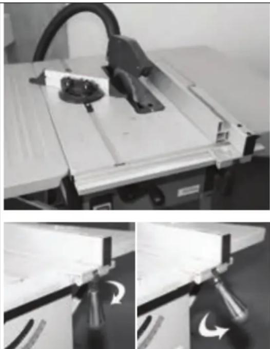
- For cutting wood lengthwise, parallel stop (Fig. 2/pos. 3) must be used.
- The stop may be used on either side of the bench.
- Lift the clamping lever (Fig. 2/pos. 6) and shift the parallel stop (Fig. 2/pos. 3) to the required position.
- Retighten the clamping lever (Fig. 2/pos. 6).

Caution: Do not move the stop too
far in the direction of the saw disc! The distance between the stop and the disc must be 20 mm at least.
Mitre cut stop

natural_image
Industrial machine with a curved arm and mechanical components (no visible text or symbols)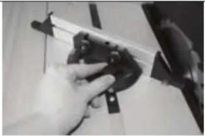
natural_image
Close-up of a hand holding a small mechanical component on a workbench (no visible text or symbols)Fig. 8
- Put the mitre cut stop (Fig. 2/pos. 14) in the respective clamp on the bench.
- Release the mitre cut stop (Fig. 2/pos. 14) with the knurled screw. Turn the stop for the arrow to stop at a required angle
• Retighten the knurled screw

Caution: Do not move the stop too
far in the direction of the saw disc! The distance between the stop and the disc must be 20 mm at least.
Cutting Angle Setting
natural_image
Close-up of mechanical components including a curved tool and a gear mechanism (no visible text or symbols)
natural_image
Hand holding a small mechanical device with a curved handle and labeled 'CE' in the corner (no readable text or symbols on the device itself)Fig. 9
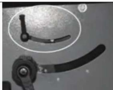
- It is possible to read the disc set-up 0^ - 45^ from the scale (Fig 2/pos 7).
Loosening both the lock lever (Fig. 2/pos. 12) and turning the wheel Fig. 2/pos. 10), the disc inclination may be changed.
Cutting depth set-up

natural_image
Hand holding a mechanical clamp device with a smartphone in the background (no visible text or symbols)Fig. 10
- Cutting depth may be set-up by turning hand wheel (Fig. 2/pos. 9)
- Turning had wheel to the left = smaller cutting depth
- Turning hand wheel to the right = bigger cutting depth.
Unit On/Off switching

natural_image
Close-up of a mechanical electrical switch or bracket with a circular component and mounting holes (no visible text or symbols)
natural_image
Close-up of a mechanical switch or connector with a circular button and a magnified inset showing a threaded component (no text or symbols visible)- Press the green knob "I" to switch the unit on.
- To switch it off, press the red knob "0".
The unit is equipped with a lockable overloading protection emergency switch.
An emergency switch is provided.
Lengthwise Cutting

natural_image
Industrial machine with clamping mechanism and metal components on a workbench (no visible text or symbols)Fig. 12
- Set the parallel stop (Fig. 2/pos. 3) at the required width in relation to the saw disc.
- Lay the work on the bearing surface are, the flatter/wider side should lay flat on the saw bench.
- Guide the wider work with hand, the smaller one with use of a sliding guide rod (Fig. 1/pos. 11).

Chamfer cuts

natural_image
Close-up of mechanical components including a curved tool and a handle, with no visible text or symbols.
natural_image
Hand holding a small mechanical device with a curved handle and circular components (no visible text or symbols)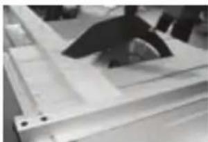
natural_image
Close-up of a mechanical assembly with a black component mounted on a white base (no visible text or symbols)
Fig. 13
- Release the lock lever (Fig. 2/pos. 12) and set the required angle on the rotary wheel (Fig. 2/pos. 10)
- Make sure that the splitting wedge (Fig. 2/pos. 18) is always flushed with the disc.
- Secure lock laver (Fig. 2/pos. 12) again
- Chamfer cuts should be always done using the parallel stop (Fig. 2/pos. 3).
Cross Cutting

natural_image
Close-up of a mechanical device on a workbench with no visible text or symbolsFig. 14

natural_image
Simple geometric shape with two diagonal lines inside a rectangle (no text or symbols)- Put the cross stop into one of two grooves on the saw bench and set up the required angle measure.
- If the disc is to be adjusted at an angle as well (see Fig. 15), a groove should be used to prevent any contact of your hand and of the cross stop with the disc cover.

Caution: Hold the worked piece
tightly, never cut a piece held loosely..
Splitting wedge set-up

natural_image
Close-up of hands adjusting a mechanical component with a tool (no visible text or symbols)Fig. 15
Maximum cuts:
Distance between the bench and the splitting wedge upper edge 10 cm approximately.
Undercuts:
The splitting wedge tip 2 mm below the saw tooth upper point. Distance between the splitting wedge and the saw disc 3-8 mm.
- Remove the saw disc cover (Fig. 2/pos. 1).
- Remove the removable part of the bench and loosen both the screws on the bench area.
- Loosen the screw on the wedge so that the wedge may be shifted – see the type of cut at issue.
- Retighten the screw, put the part of the bench in place and fix it.
- Put the disc cover back in place (Fig. 2/pos. 1).
Sawdust exhaust

natural_image
Close-up of a hand holding a flexible hose with a small arrow pointing to it (no visible text or symbols)Fig. 17
- If the unit is operated in closed rooms, it should be connected to a suitable sawdust exhaust.
Operator Safety Instructions
• Before switching the unit on, all the safety and protection devices have to be fitted at correct places.
- Never cut pieces of wood so small that they cannot be held safely.
• The saw disc has to turn freely.
- If working wood treated or processed in any way before, special attention should be paid to nails, screws etc. Before getting down to work, remove any foreign objects.
• Before switching the main switch on, make sure the saw disc is fitted correctly and all the unit moving parts are free.
- Warning! If in doubt at the assembly of this circular bench saw, consult an expert at an authorised servicing centre.
- Do not use the unit before you have read the operating manual carefully.
- Observe all the safety instructions indicated in the manual.
- Be responsible to the others.
Step by Step Instructions
- Set up the stops according to the cut to be done.
- Switch on the unit
- Push the piece to be worked slowly and evenly using the sliding guide bar to the saw disc so that the cut may be completed.
- Switch off the saw and wait for the disc to come to a standstill.
- Now, take the piece out.
Troubles – Causes – Troubleshooting
Caution: Always check the overheating protection first!
| Trouble Cause Troubleshooting | ||
| Motor will not run | 1. No power supply to the unit .2. Thermal sensor has interrupted power supply . | 1. Check the supply and power line, invite an expert electrician to consult.2. Wait for 5-10 min and switch on again.. |
| Motor will shut off in the course of work. | 1. Thermal sensor defective2. Motor circuit breaker3. Switches off for overloading. | 1. Have the replacement done by an expert electrician only.2. Wait for the motor to cool down and restart in 5-10 min. |
| Reasons of overloading | 1. Supply line is too long or its cross section is too small.2. The saw disc is not sharp as needed.3. The chamfer of the saw disc teeth is not correct. | 1. The extension cable has to be dimensioned appropriately, 1.5 mm^2 .2. Sharpen the saw disc.3. Have chamfered by an expert. |
| Scorch traces on the piece being worked | 1. Blunt saw disc. 1. Sharpen or replace the saw disc. | disc. |
Inspections and Maintenance
Unplug the unit before any works on it.
• Use a damp cloth to clean plastic parts. Do not use detergents, solvents and pointed things either.
- Clean any dirt from the bench surface with a suitable curing compound spray.
- If the engine braking time is more than 10 s, the fast wearable parts of the engine brake may be replaced by the manufacturer or an appropriate workshop only.
- Remove the dust stuck in the vent and on movable parts with a soft brush after every use.
- Oil all the movable metal parts regularly.
Saw Disc Replacement

Caution! Switch the unit off and unplug before any maintenance, adjustment or replacement of the saw disc.
• Turn the disc height readjusting wheel (Fig. 1/pos. 9) as far as to the upper stop.
- Remove the disc protection cover (Fig. 2/pos. 1).
- Remove the bench removable part.
• Take the splitting wedge out (Fig. 2/pos. 17).
- Use a spanner to hold the spindle.
• Use another spanner to loosen the disc screw. Turn anticlockwise (clockwise thread).
- Now, turn the height adjusting wheel (Fig. 2/pos. 9) as far as to the lower stop so that the disc may be taken out easily.
- Put the disc from the hub and lift it up
- Before putting in a new or sharpened disc, clean the hub carefully.
- Putting in and securing a new disc should be done in reverse order.
- Notice! Mind the correct direction of turning! The teeth cutting edge should point in the direction of rotation i.e. forward. Mind the arrows on the disc and the protection cover!
• Put back and straighten the splitting wedge (Fig. 2/pos. 17) and protection cover t (Fig. 2/pos. 1).
• Before using the saw again make sure that all the safety and protection devices work correctly.
• Important! If you put on the disc again, turn it a little by hand and check to see that it turns freely.
• Afterwards, connect the unit and before using it, let it idle at first.
Fig. 18

natural_image
Close-up of a hand using a wrench to adjust or install a mechanical component (no visible text or symbols)Driving belt replacement
Open the bench liner, remove the splitting wedge n (Fig. 2/pos. 18) and exhaust hose (Fig. 2/pos. 15) and put the unit head up on the bench.

natural_image
Close-up of a mechanical tool interacting with a curved mechanical component (no visible text or symbols)Fig. 19
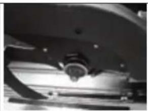
- Loosen the disc screw with wrench 24 anticlockwise while holding the disc spindle with wrench 13.
natural_image
Close-up of a mechanical component with a central circular feature and flanged base (no visible text or symbols)Fig. 20
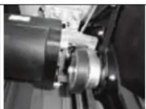
- Remove the saw disc.
natural_image
Close-up of mechanical components with no visible text or symbolsFig. 21
- Put the screwdriver behind the flat belt.
natural_image
Close-up of a car's front wheel assembly with a wrench, no visible text or symbolsFig. 22
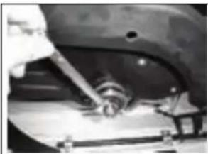
- Put wrench 13 on the disc spindle.
natural_image
Close-up of hands operating a mechanical device with no visible text or symbols
Fig. 23
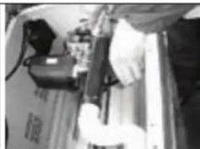
• Take the belt from the pulley using the screwdriver while turning the disc spindle in the direction of the small pulley.

natural_image
Close-up of a mechanical component with a circular base and internal components (no visible text or symbols)Fig. 24
- Turn until the belt is completely taken off the small pulley.

natural_image
Close-up of mechanical components with no visible text or symbols
natural_image
Close-up of a hand operating a mechanical joint or valve (no visible text or symbols)Fig. 25
• Now, take the belt off the big pulley.
- Push the worn belt through the pulley and dispose of it in a professional way.

natural_image
Close-up of a mechanical component with no visible text or symbols
natural_image
Close-up of a mechanical component with no visible text or symbolsFig. 26
- Push a new belt through the gap between the pulleys.
- First, see to the motor belt wheel for the grooves to fit in correctly

natural_image
Close-up of a hand operating a mechanical component with no visible text or symbolsFig. 27
- Put wrench 13 on the saw spindle again.

natural_image
Close-up of hands operating a mechanical device with a finger pointing at the button (no visible text or symbols)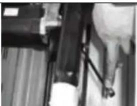
natural_image
Close-up of mechanical components with no visible text or symbolsFig. 28
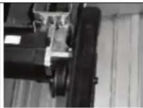
- Put the belt on big wheel now.
- Turn the screwdriver very firmly in the direction of the belt pulley
natural_image
Close-up of a mechanical component with no visible text or symbolsFig. 29
- Finished! The saw is in working order again.
Inspection and Maintenance Safety Instructions
Only a unit maintained and cared for on a regular basis may be a serviceable aid. Insufficient maintenance and care may result in emergencies and unforeseen accidents.
Inspections and Maintenance Schedule
| Time Interval Description | Other Details if | Required |
| After every use | • Dust vents and moving parts off | |
| After every use | • Dust off the whole saw. | |
| Regularly | • Oil moving metal parts. | Multipurpose oil |
| Regularly | • Check the tightness of all screws. With time, they may go loose in result of vibration. |
Service
Do you have any technical questions? A claim? Do you need spare parts or the Operating Instructions?
You will be helped quickly and without needless bureaucracy at our webpage www.guede.com in the Services part. Please help us be able to assist you. To be able to identify your appliance when claimed, we need to know its serial No., order No. and year of production. All these details can be found on the type label. Enter the details below for future reference.
Serial No.
Order No.
Year of production:
Tel.: +49 (0) 79 04 / 700-360
Fax: +49 (0) 79 04 / 700-51999
E-Mail: support@ts.guede.com
EC Declaration of Conformity
We herewith declare Güde GmbH & Co. KG
Birkichstraße 6, 74549 Wolpertshausen, Germany
That the following Appliance complies with the appropriate basic safety and health requirements of the EC Directive based on its design and type, as brought into circulation by us.
In a case of alternation of the machine, not agreed upon by us, this declaration will lose its validity.
Machine description: - TK 2400 ECO
Article-No.:
-
55166
Applicable EC Directives: - 2006/42 EC
- 2006/95 EC
- 2004/108 EC
Applicable harmonized - EN 61029-1:2009
Standards: - EN 61029-2-1:2002
- ZEK 01.2-08/12.08
- EN 55014-1:2006
- EN 50014-2:1997+A1
- EN 61000-3-2:2006
- EN 61000-3-3:1995+A1+A2
place of certification: TÜV Rheinland Product Safety GmbH
Title of Signatory: Arnold, executive

- Unit
- Scope of Delivery
- Guarantee
- General Safety Instructions
- FOLLOW THE INSTRUCTIONS BELOW CAREFULLY IN ORDER TO SECURE A HIGH DEGREE OF SAFETY:
- Caution!
- Emergency Action
- Signs on Unit
- Meaning of Symbols
- Assigned Use
- Residual Hazards and Protective Action
- Mechanical Residual Hazards
- Electrical Residual Hazards
- Noise Hazards
- Materials and Other Substances Hazards
- Human Factors Neglect
- Other Hazards
- Disposal
- Operator Requirements
- Qualification
- Minimum Age
- Training
- Transportation and Storage
- Initial Operation Safety Instruction
- Operation
- Parallel Stop
- Mitre cut stop
- Cutting Angle Setting
- Cutting depth set-up
- Unit On/Off switching
- Lengthwise Cutting
- Chamfer cuts
- Cross Cutting
- Splitting wedge set-up
- Maximum cuts:
- Undercuts:
- Sawdust exhaust
- Operator Safety Instructions
- Step by Step Instructions
- Troubles – Causes – Troubleshooting
- Inspections and Maintenance
- Saw Disc Replacement
- Driving belt replacement
- Inspection and Maintenance Safety Instructions
- Service
- EC Declaration of Conformity
Brand : Güde
Model : TK 2400 ECO
Category : Saw