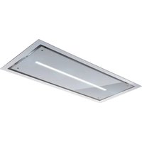
Ceiling Stripe 120 W SM - Range hood EICO - Free user manual and instructions
Find the device manual for free Ceiling Stripe 120 W SM EICO in PDF.


| Brand | EICO |
| Model | Ceiling Stripe 120 W SM |
| Category | Extractor hood |
| Operating mode | Extracting (external discharge) or recirculating (recycling with charcoal filters) |
| Power supply | 230 V ~ 50/60 Hz (check the silver label inside) |
| Maximum motor power | 690 W |
| Number of speeds | 4 (including an automatic intensive speed of 5 minutes) |
| Control types | Push buttons, Soft Touch, Digital (with display), or Remote control depending on version |
| Lighting | LED spot (replacement by qualified technician) |
| Timer | Automatic shutdown after 10 minutes |
| Metal filters | Washable every 2-3 months with hot water and non-aggressive detergent |
| Charcoal filters | Replacement every 4 months (2h/day use); also available in washable Long Life version |
| Maintenance alarm | After 100 hours of use, flashing to remind cleaning of metal filters |
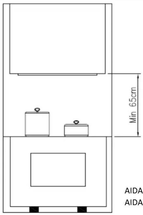
| Minimum safety distance | 65 cm between the cooking surface and the bottom of the hood |
| Power cable type | H05W-F 3 x 0.75 mm² |
| Electrical connection | Must be carried out by a qualified technician; grounding mandatory |
| Spare parts | Metal filters, charcoal filters, LED spot, remote control (optional) |
| Repairability | Replacement of LED bulb only by a qualified technician with original parts |
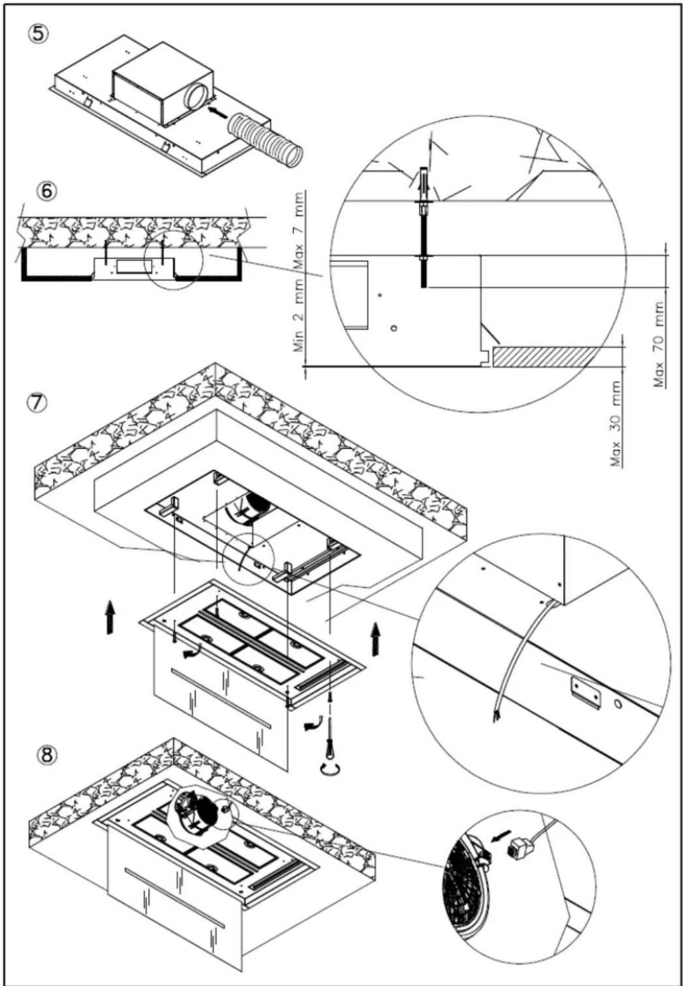
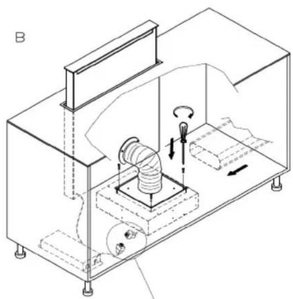
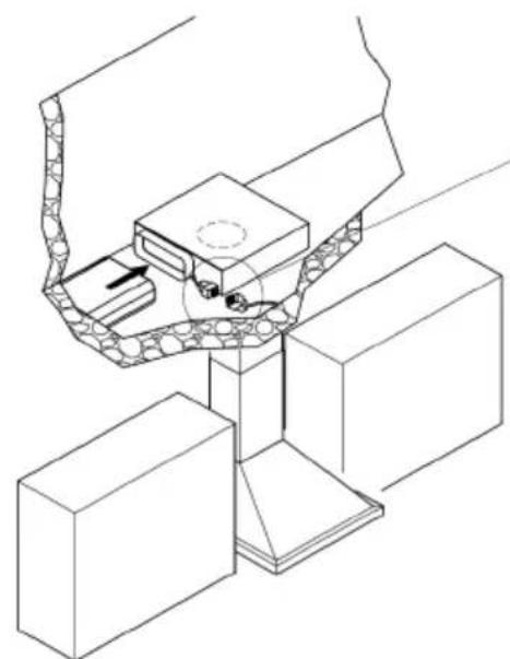
| Use with remote motor | Possible (internal connector, cable to be passed through the provided opening) |
Frequently Asked Questions - Ceiling Stripe 120 W SM EICO
User questions about Ceiling Stripe 120 W SM EICO
0 question about this device. Answer the ones you know or ask your own.
Ask a new question about this device
Download the instructions for your Range hood in PDF format for free! Find your manual Ceiling Stripe 120 W SM - EICO and take your electronic device back in hand. On this page are published all the documents necessary for the use of your device. Ceiling Stripe 120 W SM by EICO.
USER MANUAL Ceiling Stripe 120 W SM EICO
INSTRUCTIONS FOR USING, MAINTAINING AND INSTALLING THE HOOD
ATTENTION: The hood must only be installed by a qualified technician.
The company accepts no liability if it is installed by an unauthorised person.
Please read these instructions carefully before beginning the installation. Conserve this handbook together with the hood
WARNINGS
This appliance can be used by children aged from 8 years and above and persons with reduced physical, sensory or mental capabilities, or lack of experience and knowledge if they have been given supervision or instruction concerning use of the appliance in a safe way and understand the hazards involved.
Children shall not play with the appliance. Cleaning and user maintenance shall not be made by children without supervision.
Before cleaning or performing any periodic or urgent maintenance to the hood, ensure the power is turned off by removing the plug from the socket and turning the main switch to 0 (off).
Do not connect the hood to any piping used for combustion appliances, such as burners, boilers or fireplaces.
Check that the main power supply corresponds to the voltage required by the hood, which is given on the silver label stuck inside the hood. Ensure that the electric system is correctly earthed and that the earth discharge works correctly.
When cooking do not use any materials that could form high or unusual flames. Oil that has been used twice and fats are very dangerous and could easily catch fire. Do not prepare flambè dishes under the hood.
Once the specialized technician has completed the installation of the hood equipped with a remote motor, all the leads, connectors, ground connections and the remote motor must not be accessible to the user.
Only the installer is granted access by removing the screwed on panels.
CAUTION: Do not fix the lamp in operation. It can be harmful to eyes.
Respect local legislation and regulations issued by the relative authorities regarding the exhaust air when the suction is operating. Failure to respect and perform all the maintenance and cleaning operations described in this handbook could cause a fire hazard.
ATTENTION: Accessible parts may become hot when the hood is used with cooking appliances
INSTALLATION
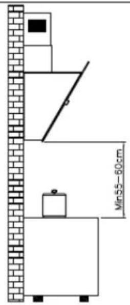
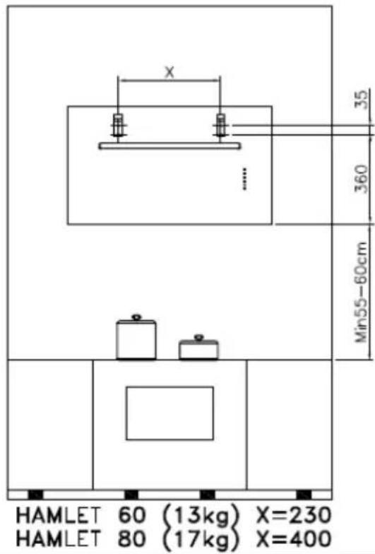
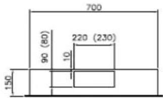
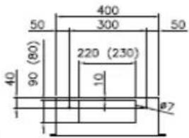
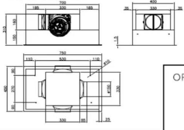
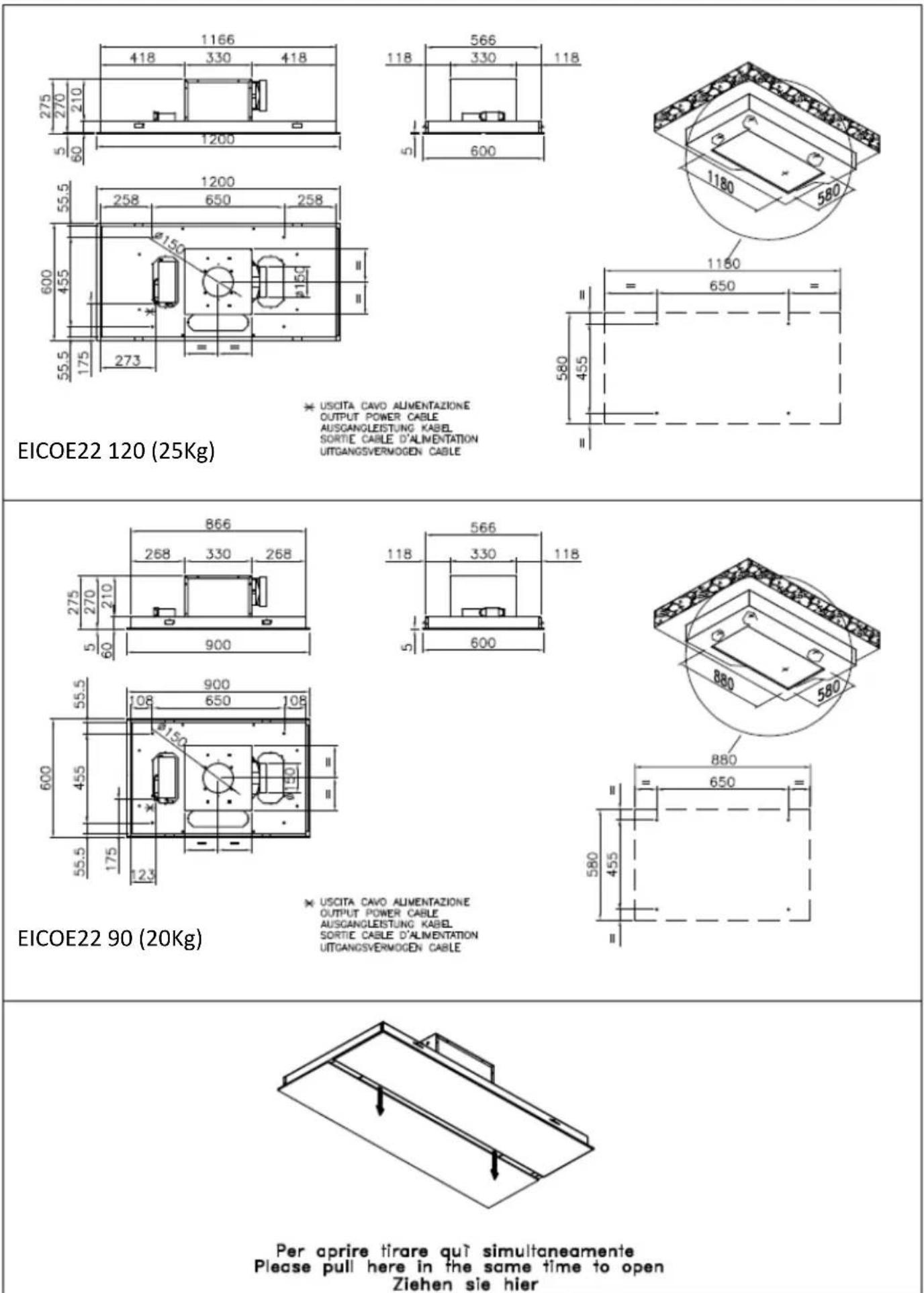
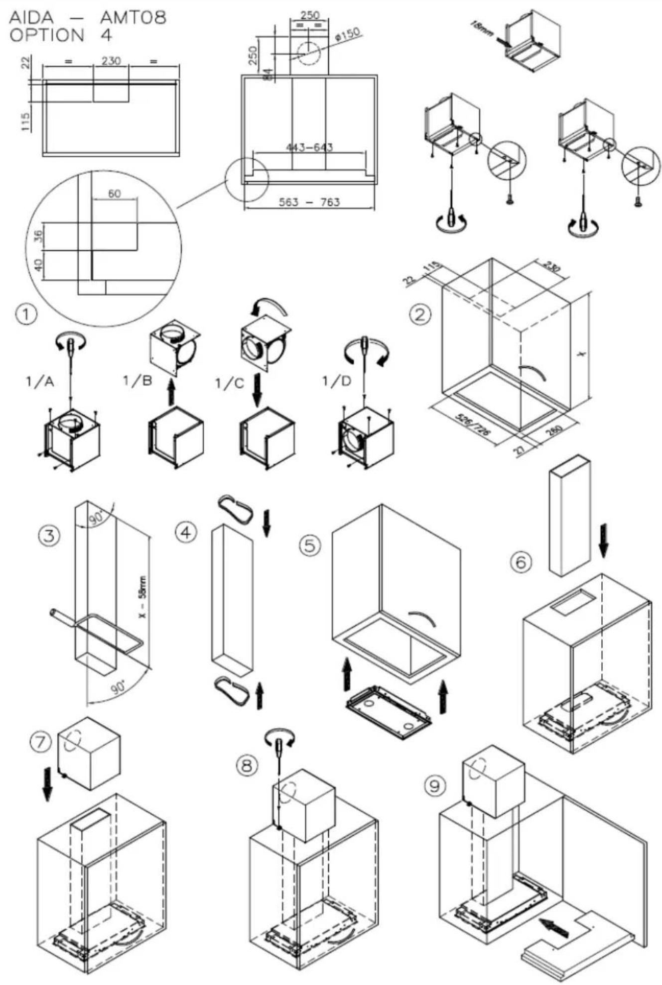
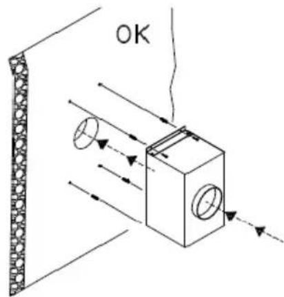
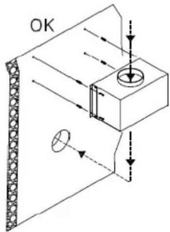
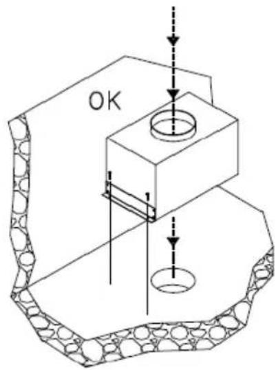
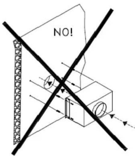
The minimum safety distance between the bottom of the hood and the top of the cooking hob must be 65 cm., smaller distances must be previously authorised by the manufacturer. (see installation drawings)
The hood can be used for both filtering and suction.
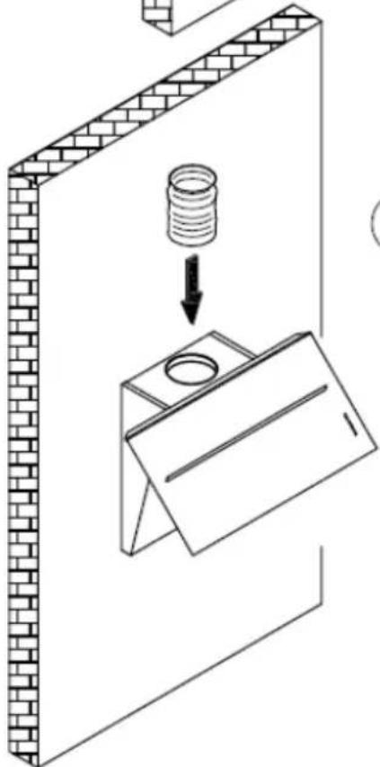
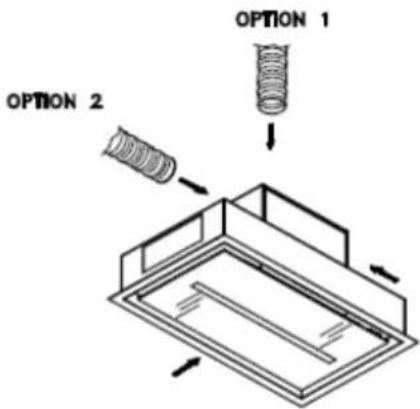
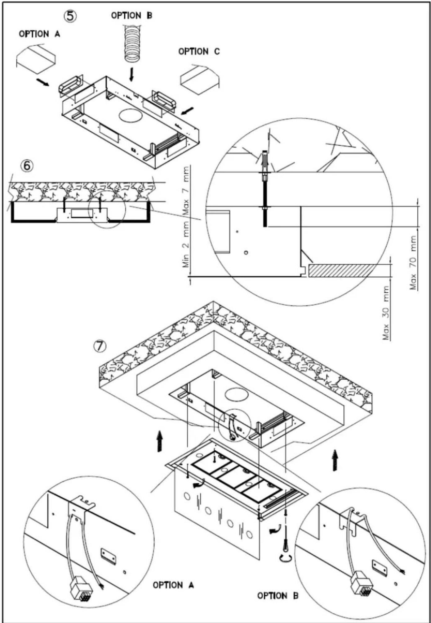
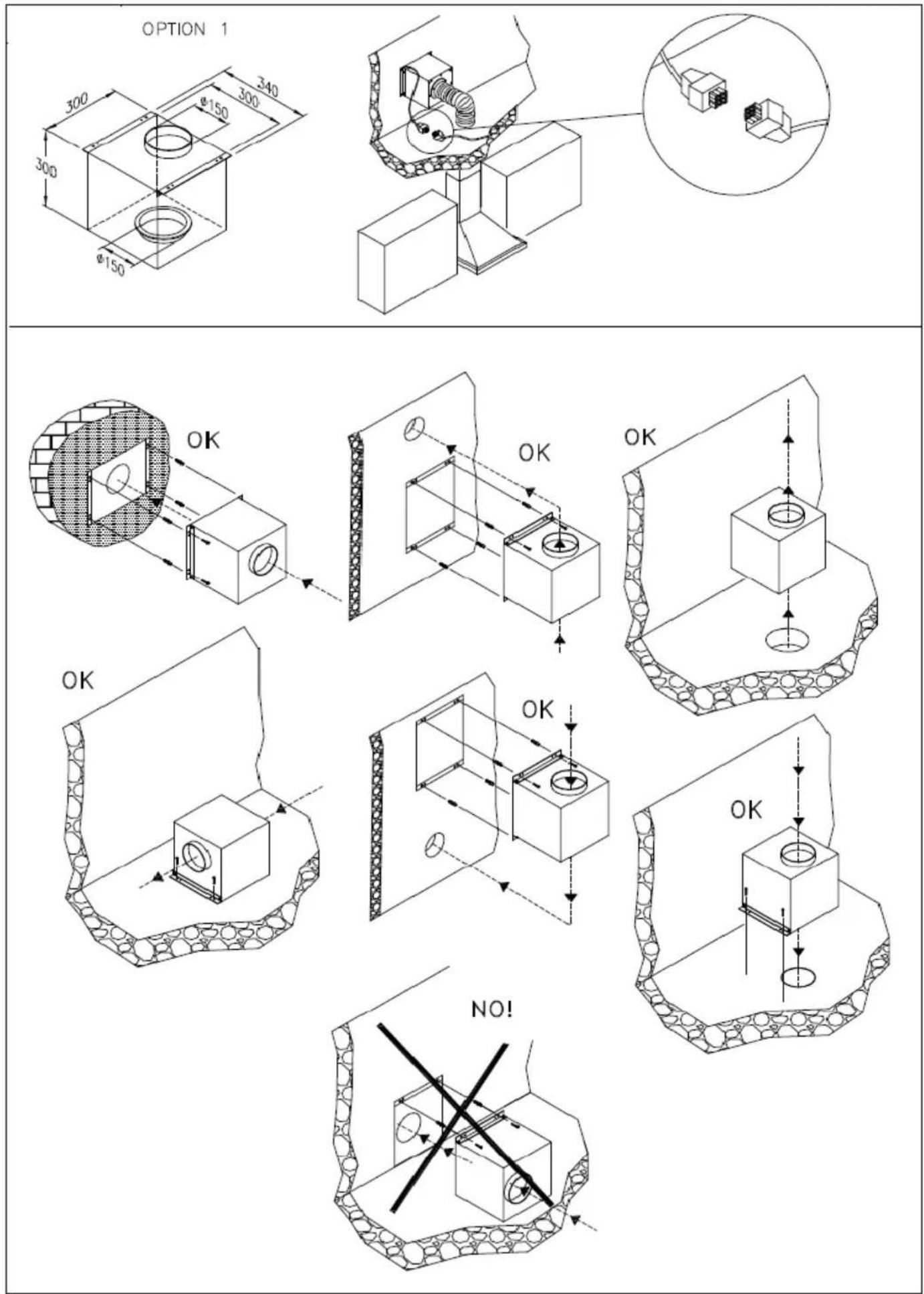
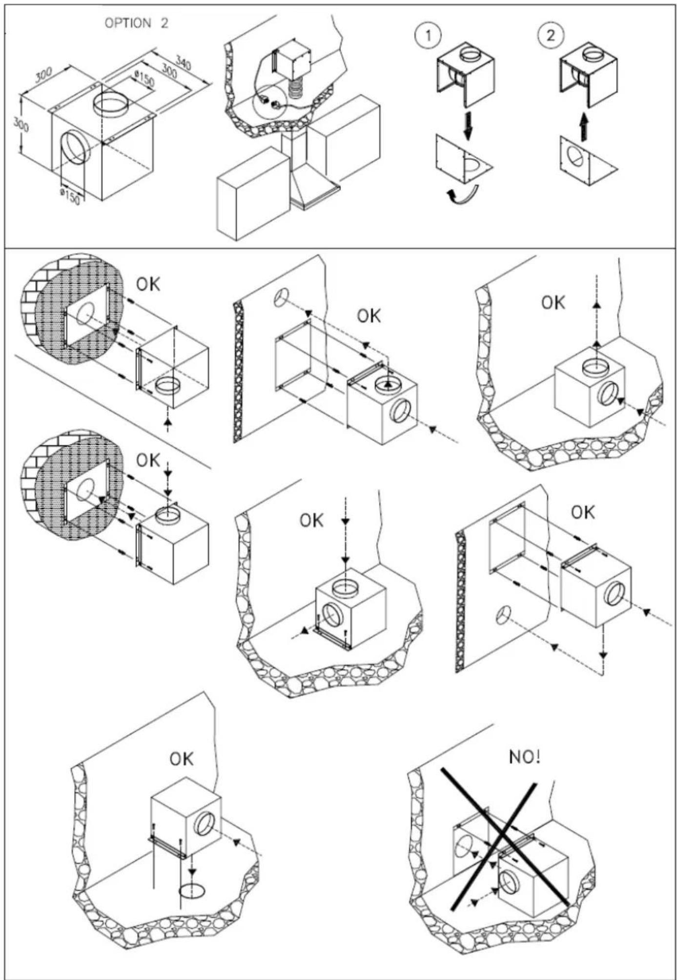
When the filtering function is operating, i.e. with air recycle, carbon filters must be used (refer to the paragraph on CARBON FILTERS). When the suction function is operating, i.e. exhausting the filtered air on the outside, a suitable compensation system must be used according to current standards in force. The diameter of the fume exhaust pipe must be the same or greater than the diameter of the hood pipe union.
There must be sufficient ventilation in the room where the hood is installed, to allow the simultaneous use of other appliances that use gas or other fuel.
Hoods equipped for remote motors
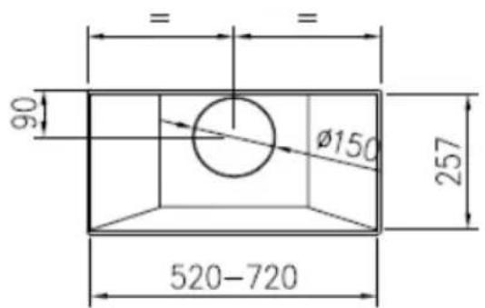
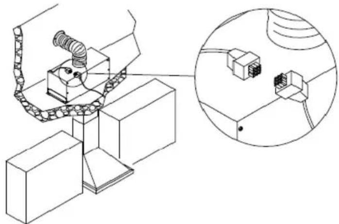
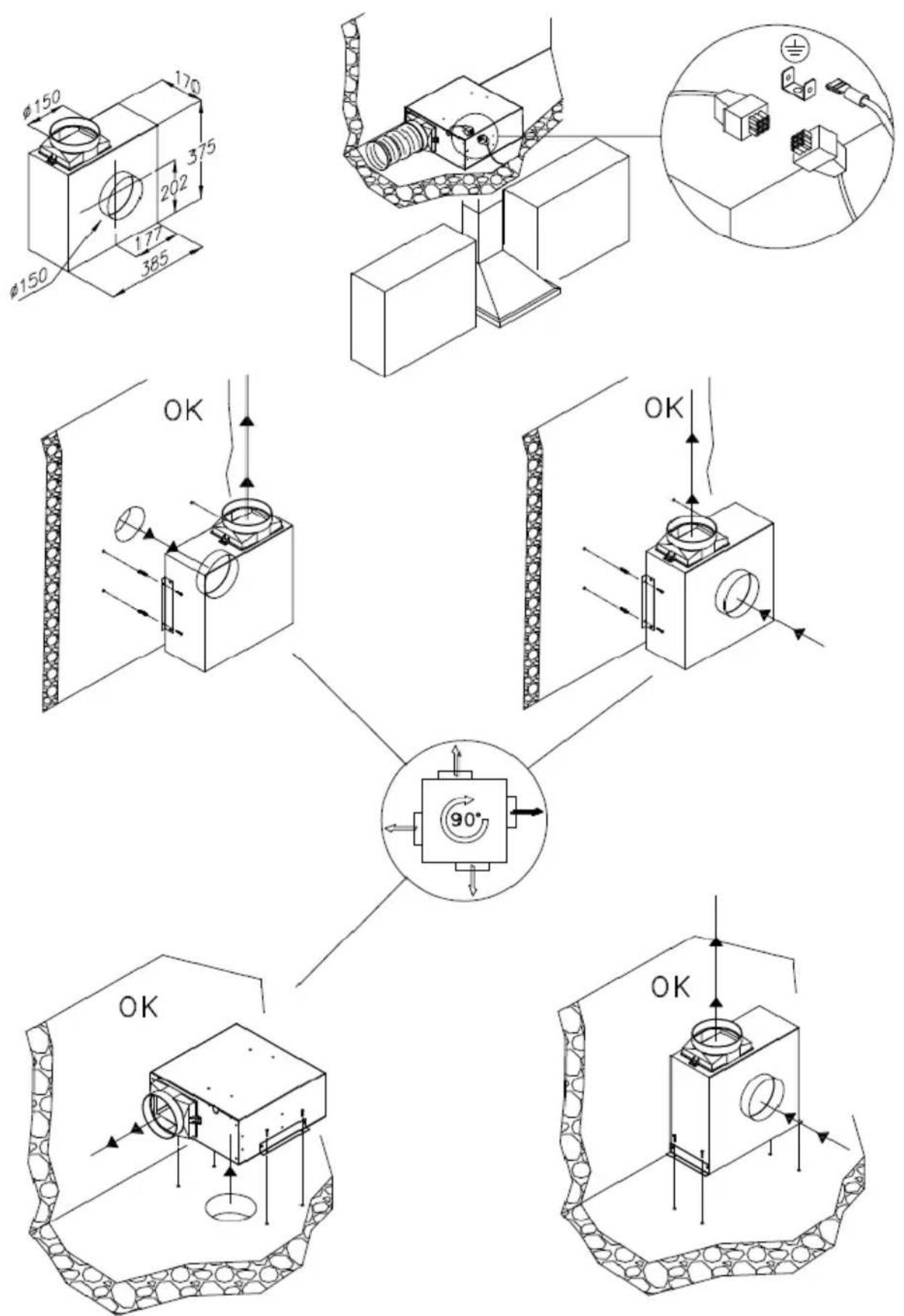
The hoods equipped for remote motors have a specific connector for the remote motor lead connection. The connector is situated inside the hood. Pass the remote motor lead into the hood through the aperture in the hood itself (usually near the fume exit hole) and join the two connectors. Refer to the figures in the remote motor instruction book when performing this operation.
Hoods without motor (Art.*0***) must only be installed and connected with extraction units with a max. output of 690W, as supplied and indicated by the manufacturer.
Once the specialized technician has completed the installation of the hood equipped with a remote motor, all the leads, connectors, ground connections and the remote motor must not be accessible to the user. Only the installer is granted access by removing the screwed on panels.
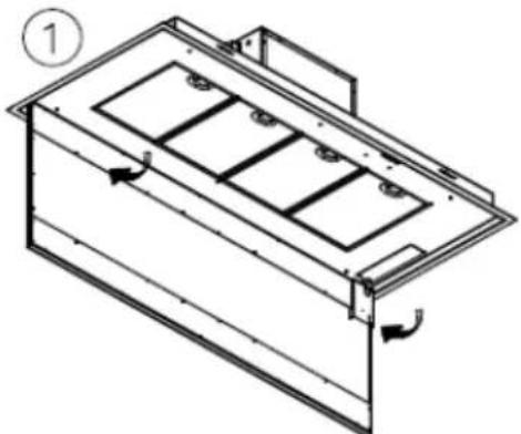
ASSEMBLY INSTRUCTIONS
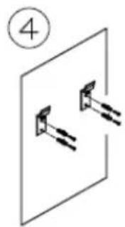
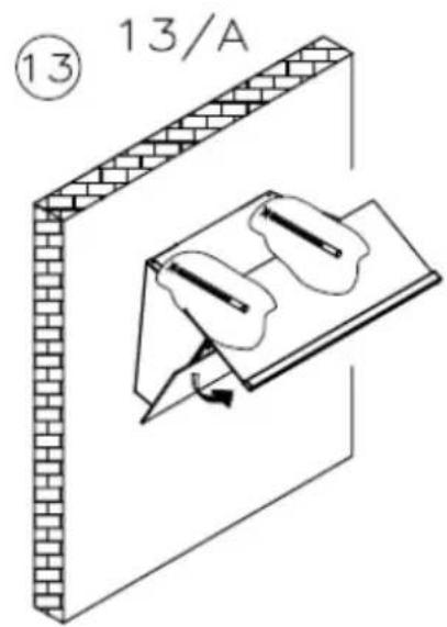
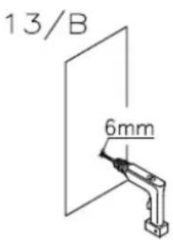
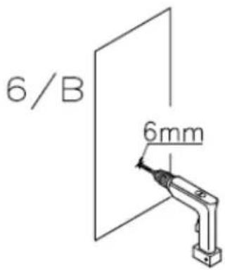
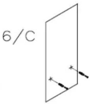
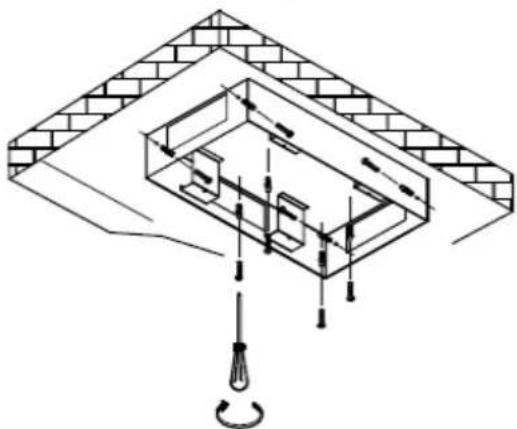
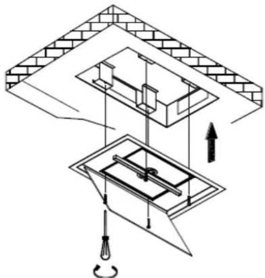
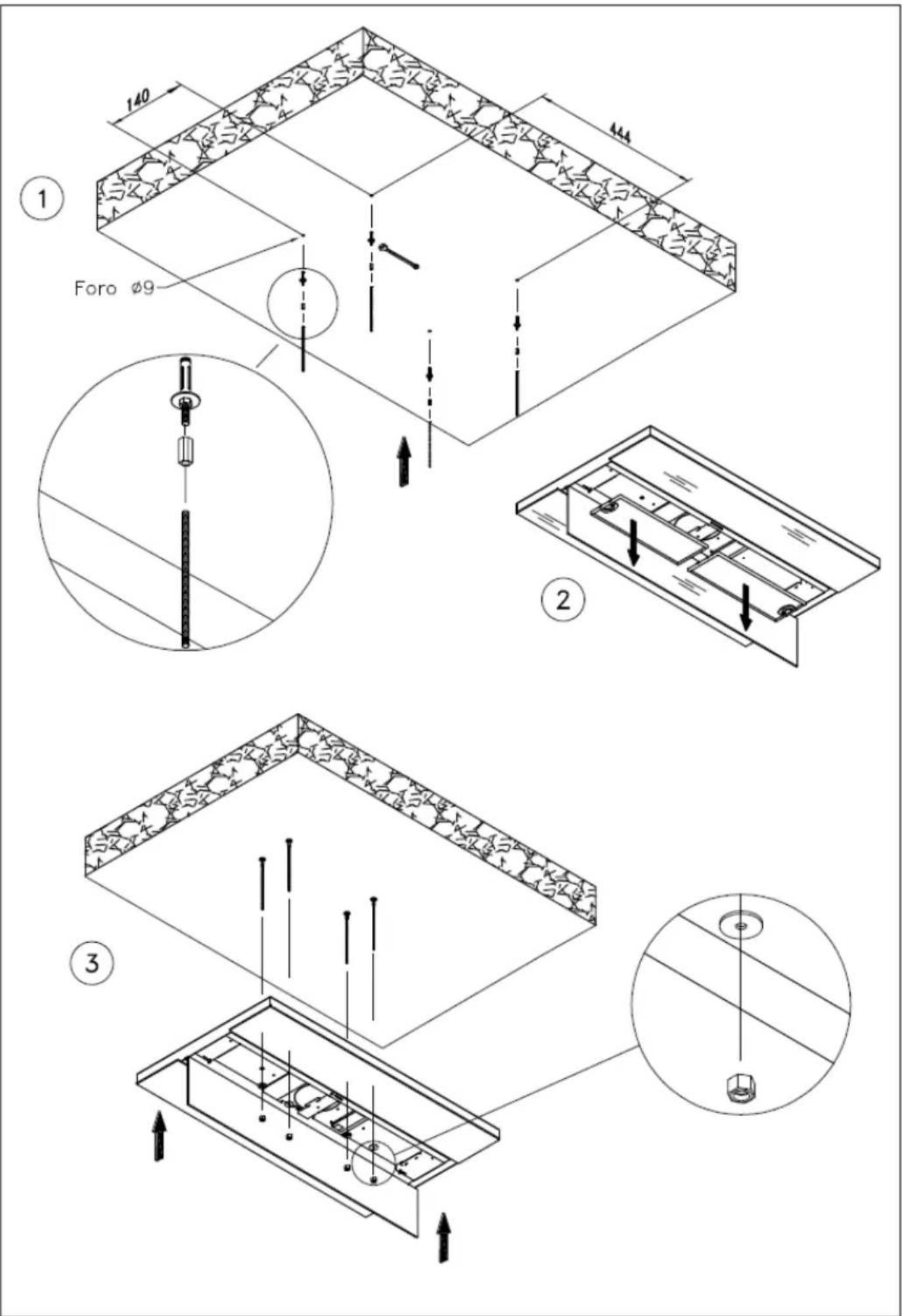
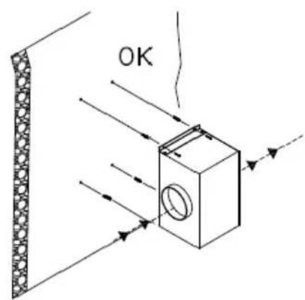
Attention: Before proceeding with the installation, make sure that the screws and the anchors already supplied, are suitable for the type of wall the hood must be fixed to.
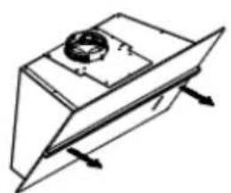
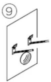
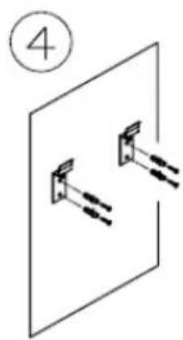
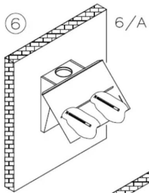
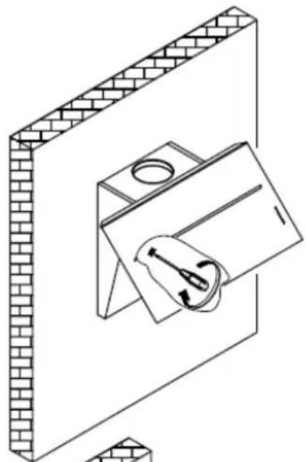
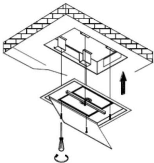
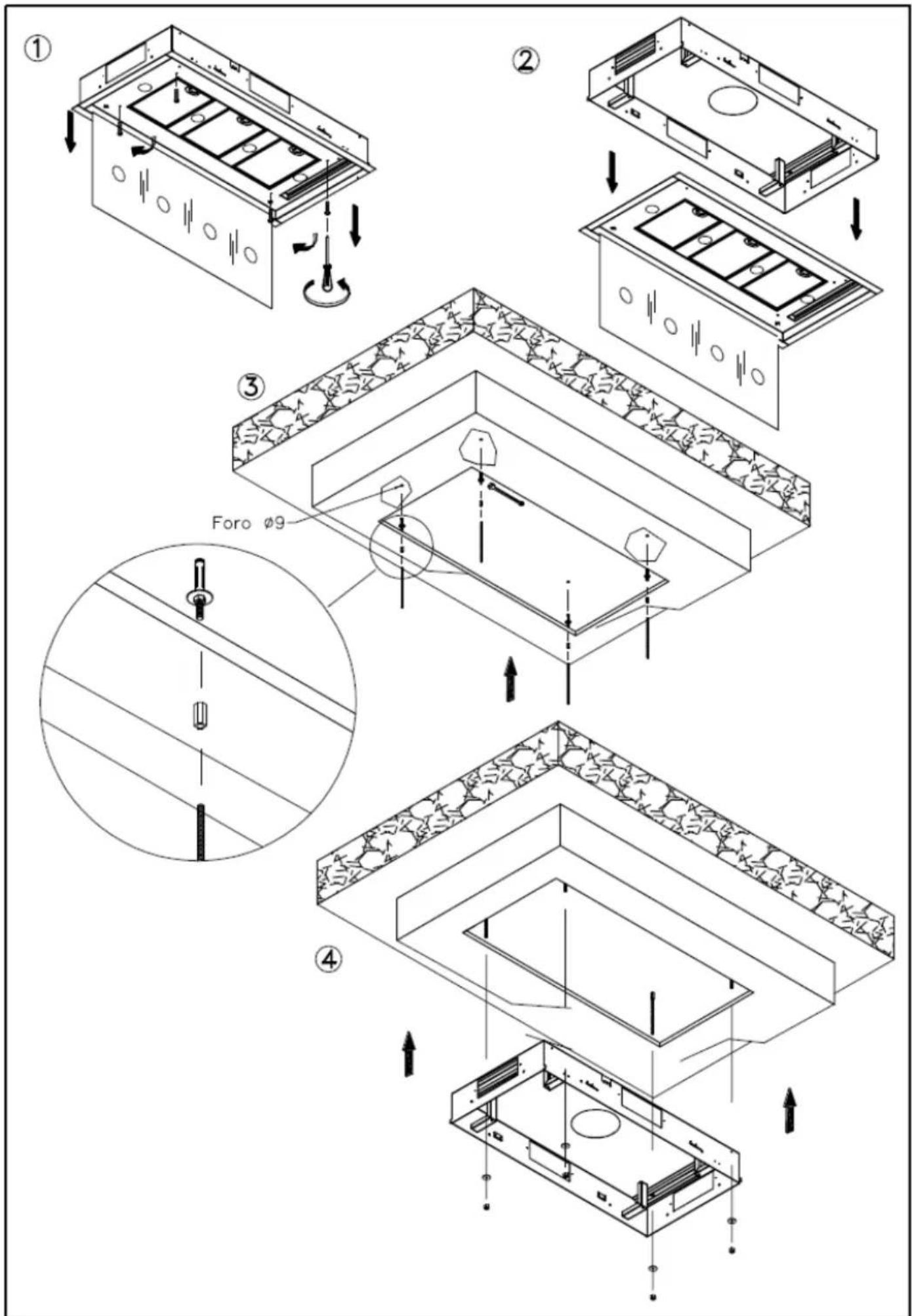
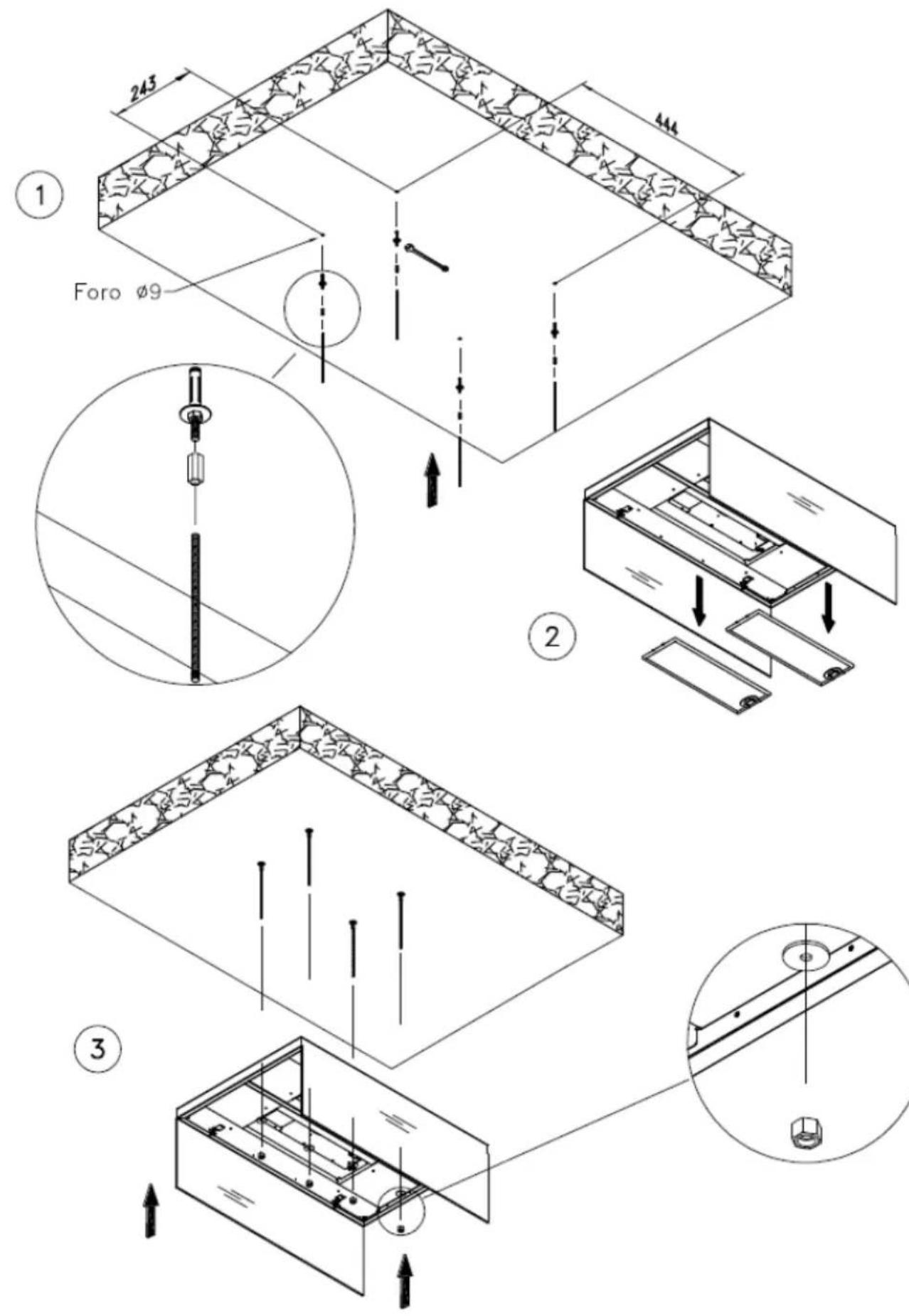
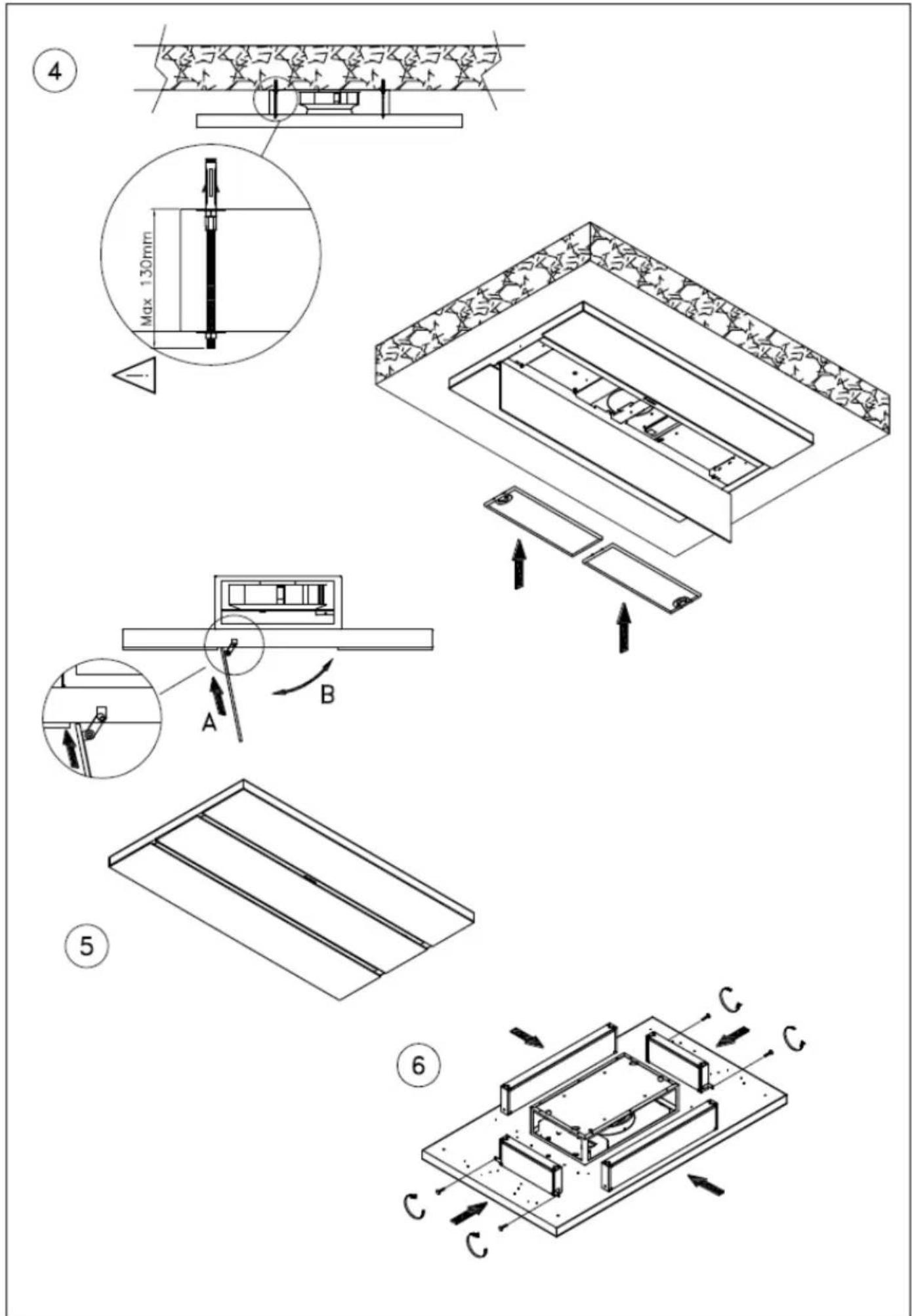
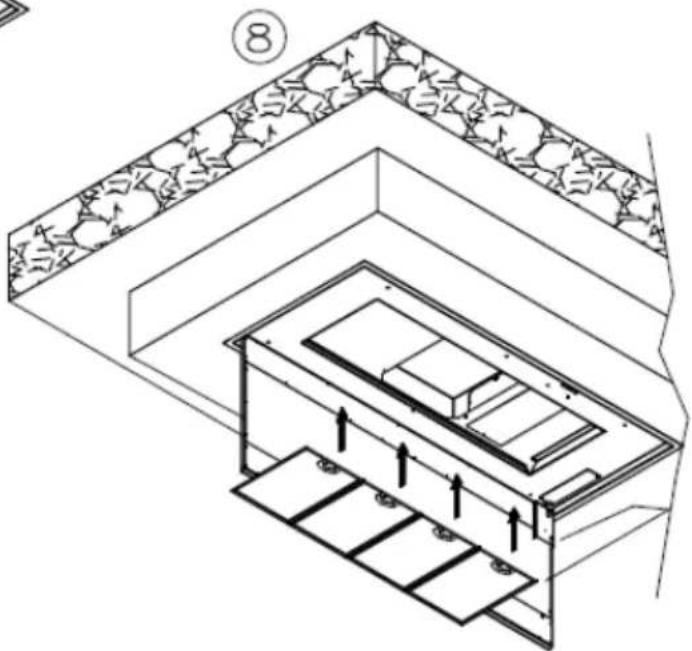
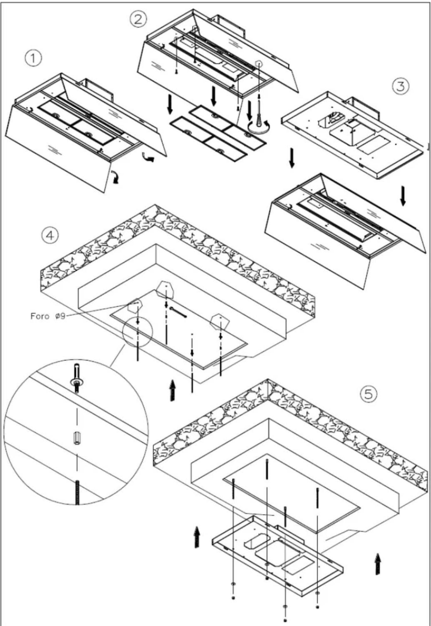
To assemble the hood use the accessories that are supplied and follow the instructions given in the enclosed handbook.
ELECTRIC WIRING
The electric wiring must be performed by a specialised electrician fully respecting current standards and legislation in force. Check that the power supply corresponds to the voltage requested by the hood, which is given on the silver label stuck inside the hood. Ensure that the wiring system conforms to current standards and the earth discharge works efficiently. Pay special attention to the hood power cable, ensure that it does not pass through any holes without a cable clamp. For direct connection to the electrical mains is necessary to provide a device that ensures disconnection from the electrical mains, with an opening distance of the contacts that allows the complete disconnection under the conditions of overvoltage category III, in accordance with the rules of installation.
The plug or omnipolar switch must be accessible when the unit is installed
If the power cord is damaged, it must be replaced by a special cord or assembly available from the manufacturer or its service agent. The cable used must be of type H05VV-F 3 x 0.75 mm2 minimum cross-section.
The manufacturer declines all responsibility if the current accident prevention standards in force are not respected, which are needed for the wiring system to operate correctly
CONTROLS
KEYBOARD CONTROLS (Fig. 1)
There are four buttons on the keyboard control version:
One for turning the lights on and off.
One for turning the motor on at 1st speed and for turning it off.
One for turning it on at 2nd speed.
One for turning it on at 3rd speed.
SOFT TOUCH CONTROL (Fig. 2)
There are four soft touch buttons on this version and a variable colour led (green min. speed, red max. speed).
One button for turning the lights on and off.
One button for turning on at 2nd speed and for turning the motor off.
N.B. If this button is kept depressed for more than three seconds, the automatic function is activated to turn the hood
off function after 10 minutes, the led flashes slowly.
Two buttons + and - for increasing and reducing the motor speed. At the 4th motor speed (intense) the led flashes quickly and after 5 minutes the 2nd speed is automatically set.
DIGITAL CONTROLS \ TOUCH CONTROLS (Fig. 3)
In this version there are five soft touch buttons and a display
One button for turning the lights on and off.
One button for turning on at 2nd speed and for turning the motor off.
Two buttons + and - for increasing and decreasing the motor speed. At the 4th motor speed (intense) the number on the display flashes and after 5 minutes the 2nd speed is automatically set.
A TIMER button for turning the motor off after 10 minutes. When the timer is activated, the number on the display flashes.
Special functions:
After 100 hours use, a D or a letter A will start flashing on the DISPLAY to remind the user to clean the metal filters. After washing the metal filters, reset the hour meter by pressing the TIMER button for more than three seconds with the hood turned off. When the hour meter has been reset a dash appears on the display, with the hood turned off.
RADIO-CONTROL (Fig. 4)
The button ON/OFF on the hood turn on simultaneously lights and the motor at the second speed or it turns off everything. After 100 working hours of the suction motor the red led will start to flash indicating the need to wash metals filters. To cancel the filters alarm, when the suction motor is switched off, you must press button ON/OFF long enough.
Radio control
ATTENTION:
The hoods with the standard remote control are already configured.
For optional and/or replacement remote controls it is necessary to start the learning process:
With the hood turned off, keep button "ON/OFF" (DISTANTE - CEILING - SKYFRAME) or button "+" (AIDA - HAMLET - ROMEO) for 5 sec. The remote control learning is indicated with the flashing alarm filters led. If within one minute arrive a valid remote control code (sent by pressing any button of the remote control) the led will be on continuously for 3 seconds and then it will turn off, indicating the proper learning.
Control buttons:
One button for turning the lights on and off. CEILING PANEL: hold the button to dim the light.
One button for turning on at 2nd speed and for turning the motor off.
Two buttons + and - for increasing and decreasing the motor speed. At the 4th motor speed (intense) the led flashes and after 5 minutes the 2nd speed is automatically set.
A TIMER button for turning the motor off after 10 minutes.
USE AND MAINTENANCE
Before beginning any sort of cleaning or maintenance work, turn power off to the hood by turning the main switch to 0 (OFF).
Changing the light bulbs
LED spotlight replacement should only be carried out by qualified technicians using only original spare parts.
Cleaning the metal filters:
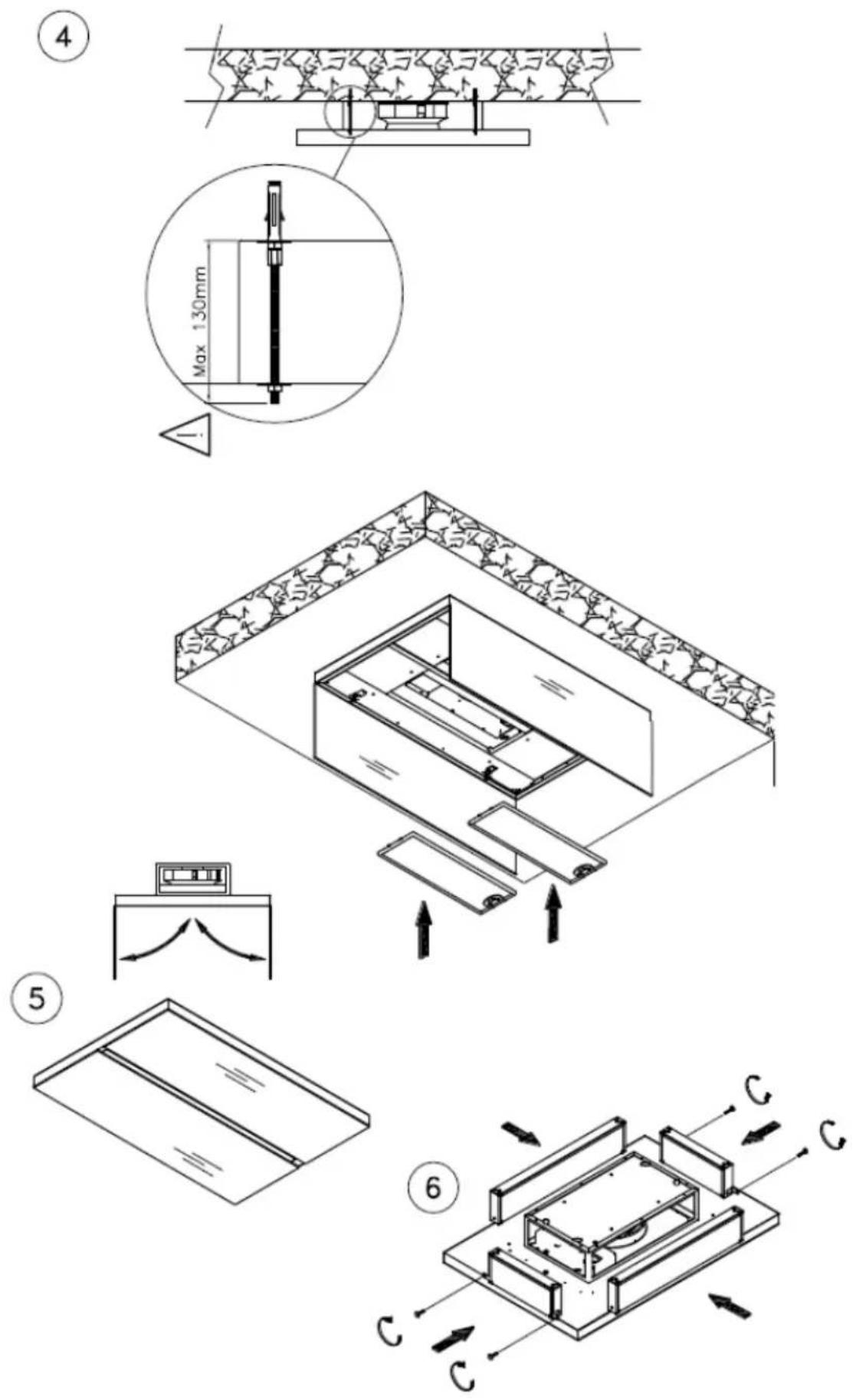
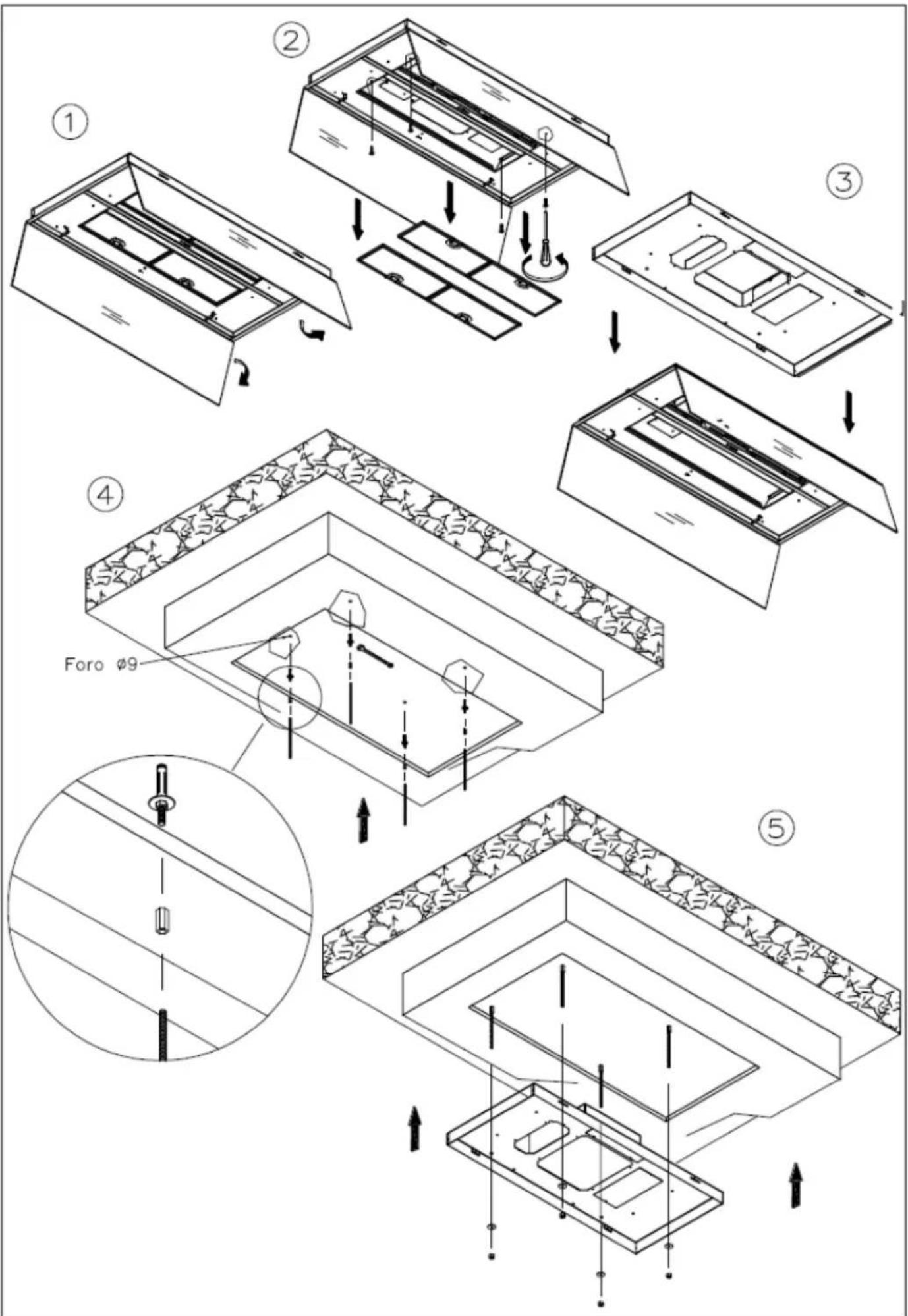
The metal filters fitted in the hood should be washed every 2-3 months, depending on how much the hood is used, using hot water and a liquid detergent that is not too aggressive. The metal filters can be removed by the special handle, unhooking the front part of the filter and pulling it downwards (Fig. 5)
Carbon filters
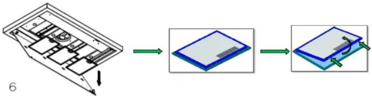
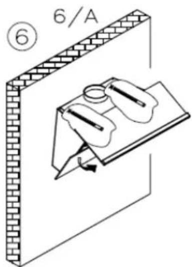
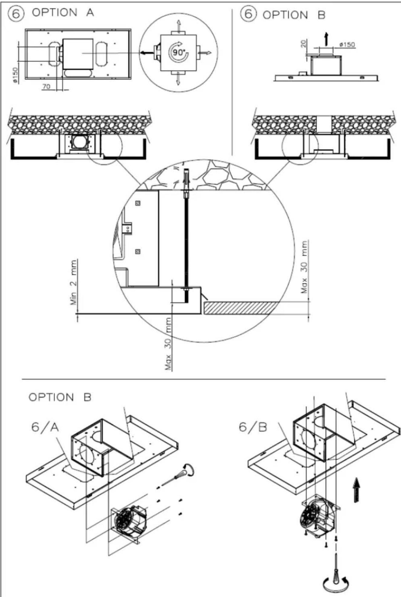
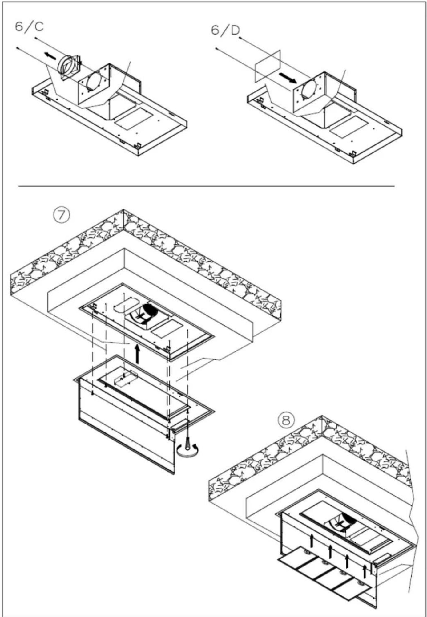
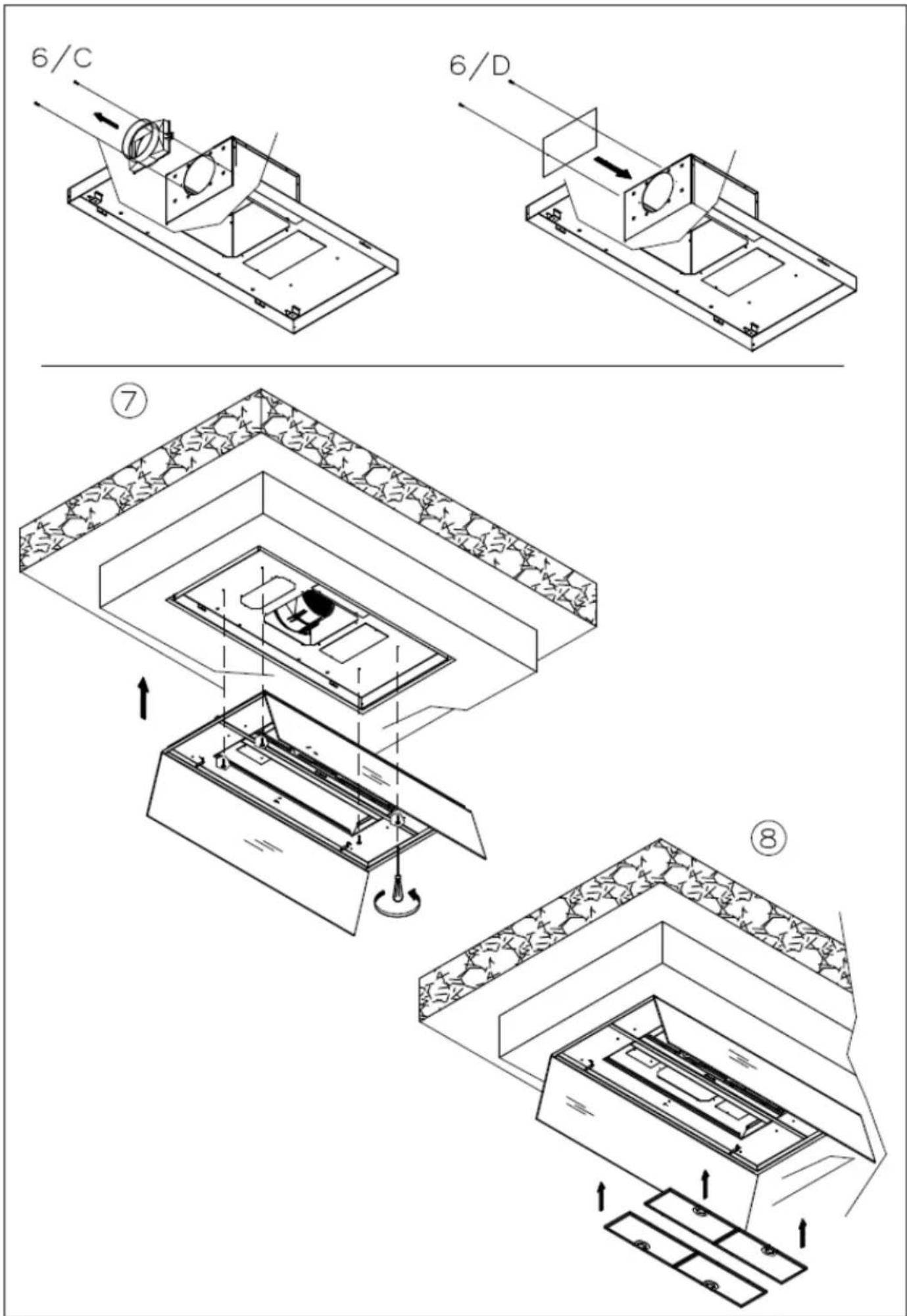
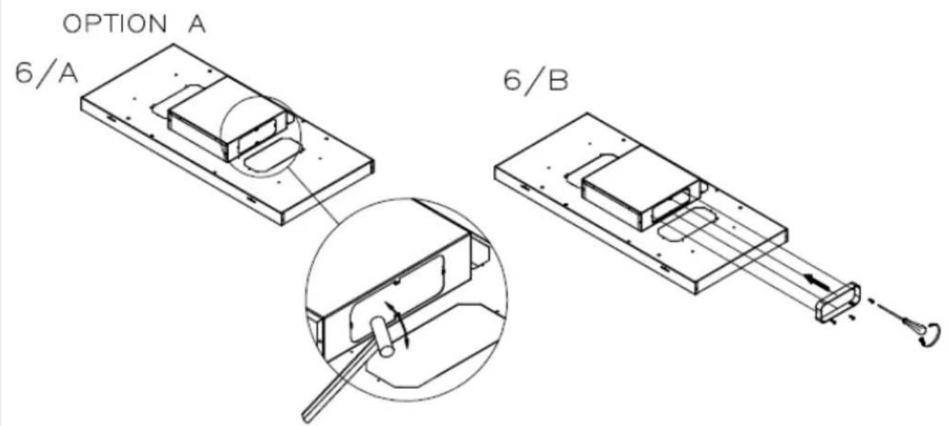
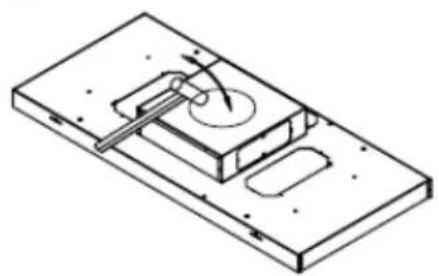
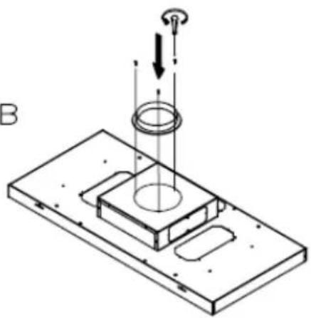
If the hood is used with an internal recycle filtering system, then active carbon filters must be used. The active carbon in the filters traps the cooking smells. To remove and change the filters, refer to fig. 6
POLYESTER carbon filters cannot be reused or washed and must be periodically changed (every 4 months if the hood is used for 2 hours every day). Saturate filters could be a fire hazard.
Depending on the hood model, the carbon filters are round or rectangular.
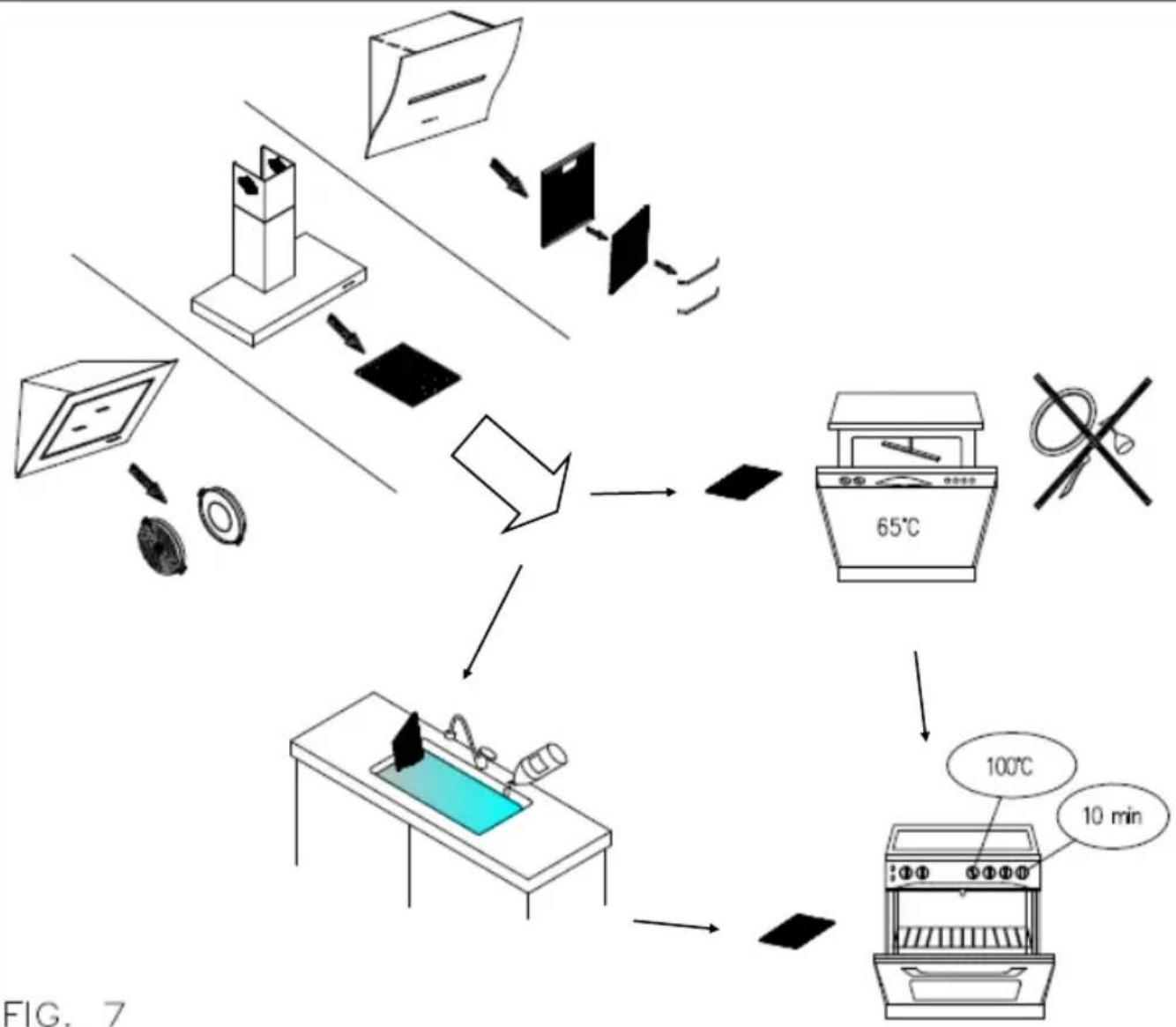
LONG LIFE carbon filter can be cleaned and reactivated. The filter should be cleaned every other month if used normally. The filter is best cleaned in a dishwasher at the highest temperature using normal washer detergent. The filter should be washed on its own to prevent particles of food from fastening in it and then causing an unpleasant smell later on. To reactivate the carbon the filter should be dried in the oven. Chose upper/ lower heat and maximum 100°C and try the filter for 10 minutes. The filter must be changed when it no longer absorbs the cooking smells sufficiently. (fig.7)
Condensation in the hood
Induction or glass ceramic hobs heat food up very quickly, creating cooking steam before the glass or steel surface of the hood has heated up, which causes condensation on the hood that then drips. Another cause for condensation could be that the fume pipe is not the size we recommend (see INSTALLATION). The steam that remains inside the hood while it is cooling down condensates and drips. Therefore it is advisable to turn the hood on ten minutes before starting to cook and when you have finished, leave it on so that all the fumes in the pipe are expelled.
Furthermore, it is important to clean the filters frequently and if they are worn they should be replaced (see CLEANING THE METAL FILTERS).
Cleaning the hood
The surfaces of the hood should be cleaned frequently, to avoid the risk of having to remove built up and encrusted deposits and stains.
For the painted or copper plated hoods just use a soft cloth with warm water and a neutral detergent. Do not pour the detergent directly onto the hood or use powdery or abrasive products
For the stainless steel hood, use special products and cloths for satin finish stainless steel (not abrasive, corrosive detergents or detergents containing chloride), ensuring to clean in the same direction as the satin finish.
Do not use aggressive products, chemical solvents or derivatives of oil distillates that could leave oily traces which could cause oxidation and polymerisation.
Hamlet - Romeo: when you use oil to cook the oil will run to the lowest part of the hood, and this edge should be cleaned more often than normally.
The manufacturer accepts no responsibility for damage to the surface of the hood due to failure to respect these instructions.
BEDIENUNGS-, WARTUNGS- UND INSTALLATIONSHANDBUCH ABZUGSHAUBE
natural_image
Isometric view of a rectangular tray filled with granular material, no text or symbols visibleMOD. DISTANTE R
flowchart
graph TD
    A["Step 6: Component selection"] --> B["Step 1: Blue panel with gray center"]
    B --> C["Step 2: Blue panel with green arrows indicating motion"]
    style A fill:#f9f,stroke:#333
    style C fill:#bbf,stroke:#333
FIG. 6
flowchart
graph TD
    A["Household with monitor"] --> B["Receiving fan"]
    B --> C["Computer with monitor"]
    C --> D["Product box with lid"]
    D --> E["Product box with tray"]
    E --> F["Product box with tray"]
    F --> G["Product box with tray"]
    G --> H["Product box with tray"]
    H --> I["Product box with tray"]
    I --> J["Product box with tray"]
    J --> K["Product box with tray"]
    K --> L["Product box with tray"]
    L --> M["Product box with tray"]
    M --> N["Product box with tray"]
    N --> O["Product box with tray"]
    O --> P["Product box with tray"]
    P --> Q["Product box with tray"]
    Q --> R["Product box with tray"]
    R --> S["Product box with tray"]
    S --> T["Product box with tray"]
    T --> U["Product box with tray"]
    U --> V["Product box with tray"]
    V --> W["Product box with tray"]
    W --> X["Product box with tray"]
    X --> Y["Product box with tray"]
    Y --> Z["Product box with tray"]
ROMEO
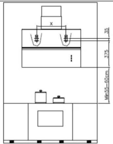
ROMEO 80 X=400
ROMEO 60 X=315
natural_image
Simple line drawing of a mechanical component with arrows indicating direction (no text or symbols)natural_image
Isometric diagram of a brick wall with a panel and two tools, no text or symbols present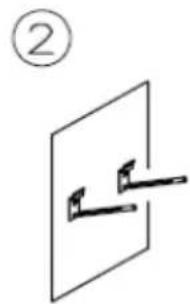
natural_image
Simple line drawing of a mechanical lever or pivot with two pivots, no text or symbols present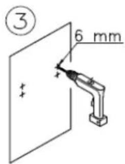
natural_image
Simple line drawing of two wall-mounted sensors mounted on a panel, with no text or symbols present.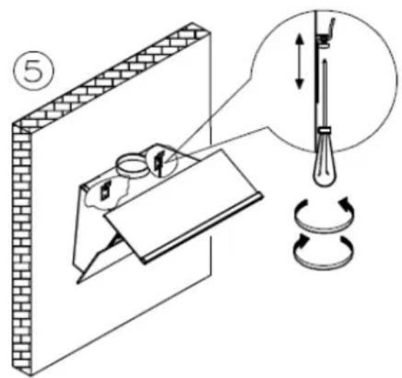
natural_image
Isometric line drawing of a mechanical assembly with two gears and a base plate, no text or symbols present
ROMEO
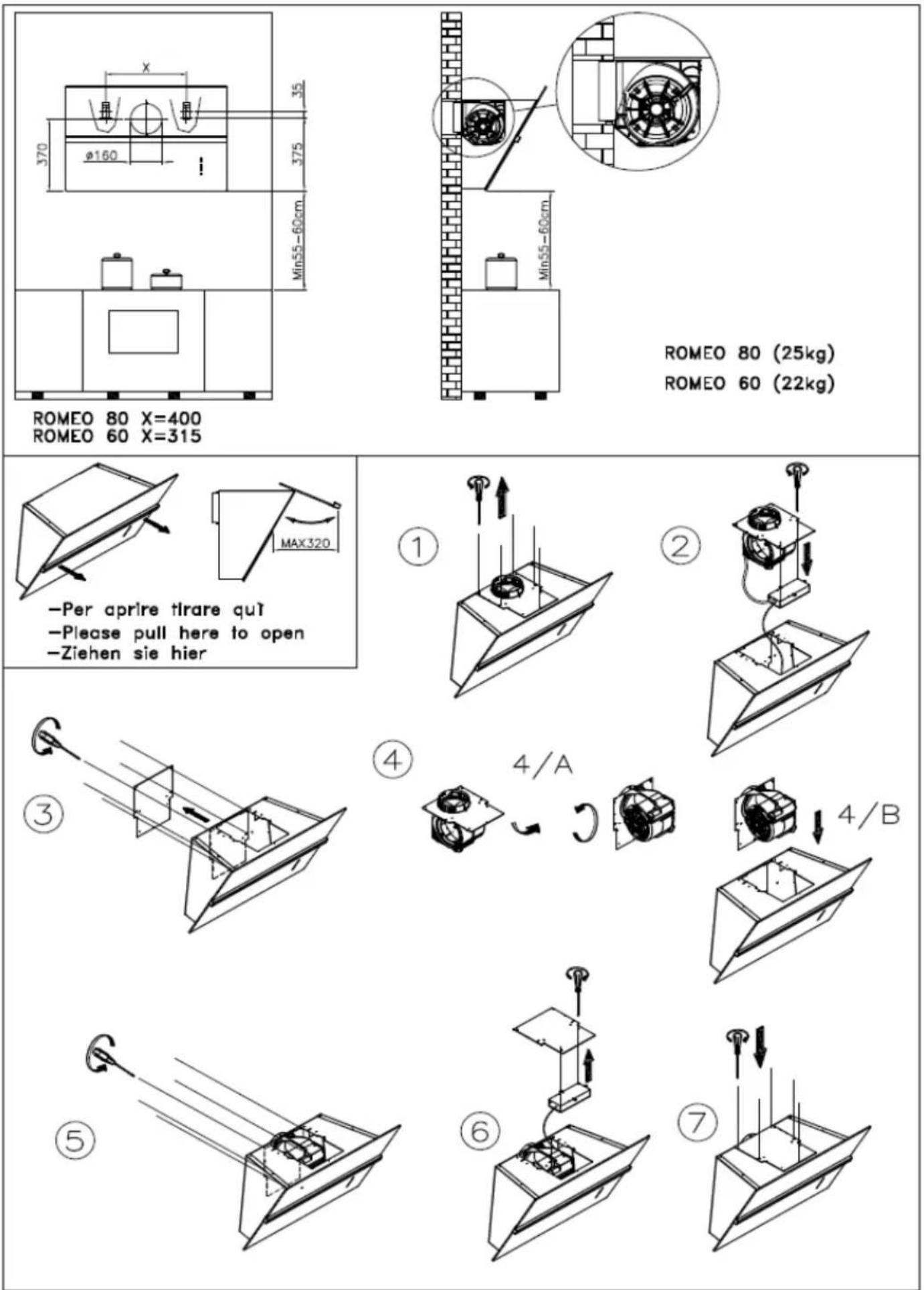
ROMEO 80 X=400
ROMEO 60 X=315
ROMEO 80 (25kg)
ROMEO 60 (22kg)
-Per aprire tirare qu'
-Please pull here to open
-Ziehen sie hier

natural_image
Simple line drawing of a mechanical lever system with a circular component, no text or symbols present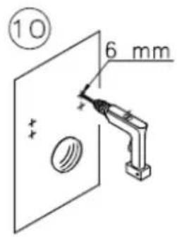

natural_image
Diagram showing two wall-mounted fixtures mounted on a panel, with no visible text or symbols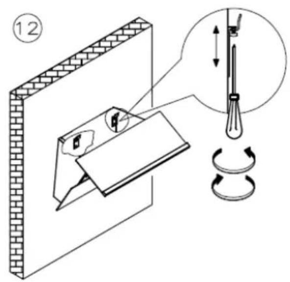

chemical
Simple chemical structure diagram labeled 13/C with two arrows indicating direction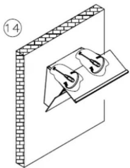
natural_image
Isometric diagram of a brick wall with two mechanical components mounted on a base plate (no text or symbols)HAMLET
natural_image
Pure 3D diagram of a mechanical component with arrows indicating direction (no text or symbols)Per aprire tirare quit simultaneamente Please pull here in the same time to open Ziehen sie hier
natural_image
Isometric diagram of a brick wall with a window and two horizontal bars, no text or symbols present
natural_image
Simple line drawing of a mechanical lever or bracket mounted on a flat plate, labeled with circled number 2 (no text or symbols on the diagram itself)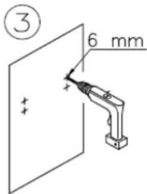
natural_image
Simple line drawing of two wall-mounted sensors mounted on a panel, with no text or symbols present.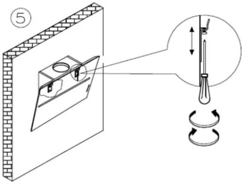
⑦
natural_image
Isometric line drawing of a mechanical assembly with a bracket and housing (no text or symbols)8
natural_image
Diagram showing a mechanical assembly with a spring-loaded component and a base plate, no text or symbols present.⑨
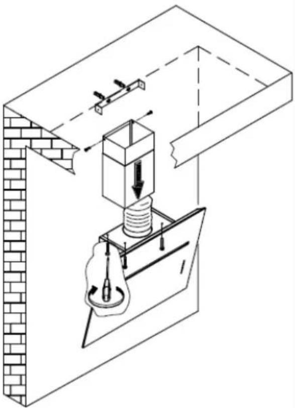
natural_image
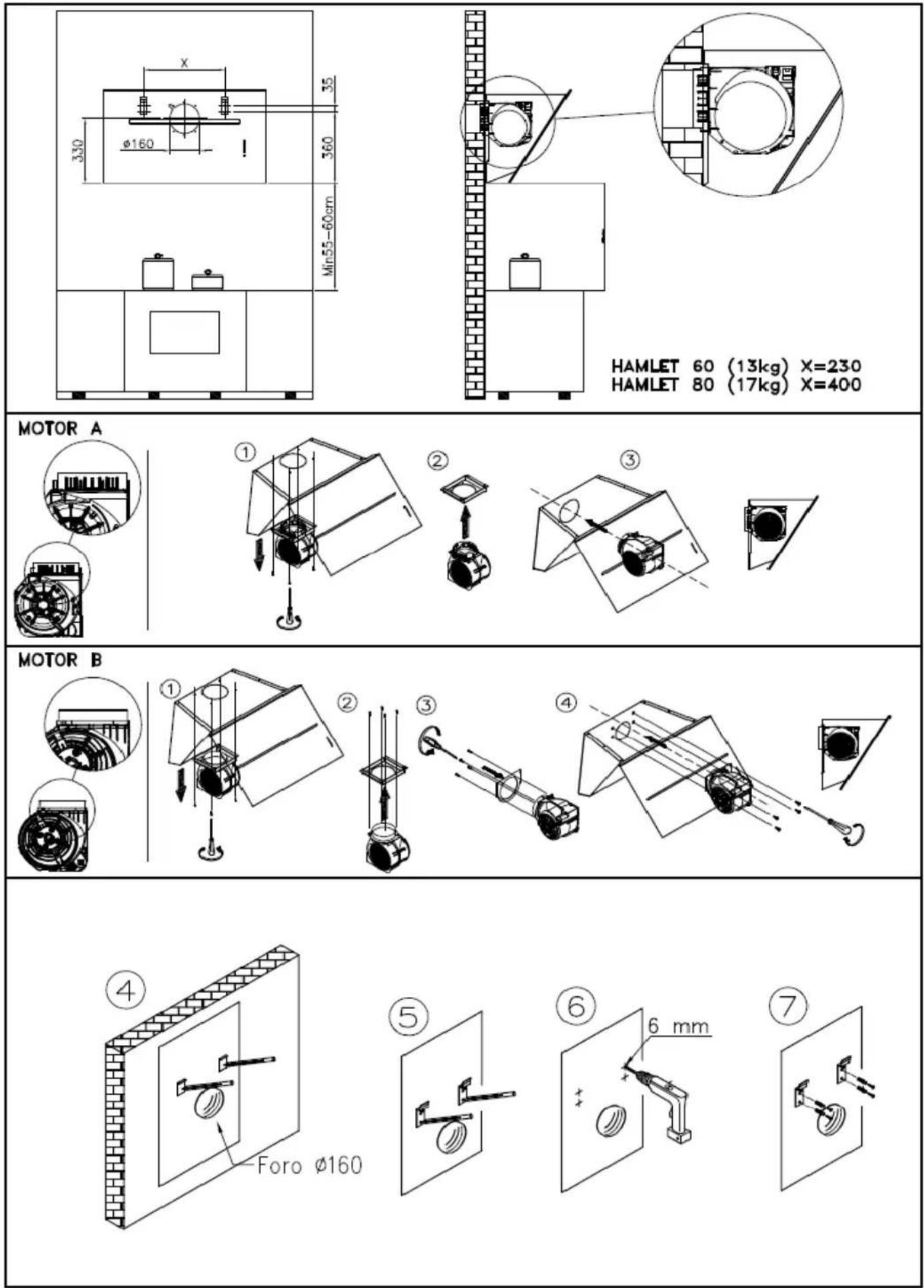
Technical diagram of a mechanical assembly with a spring-loaded component and supporting beams (no text or labels)HAMLET
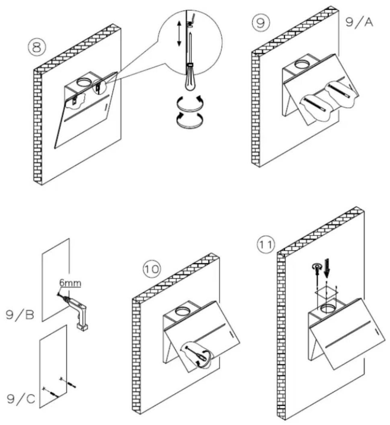
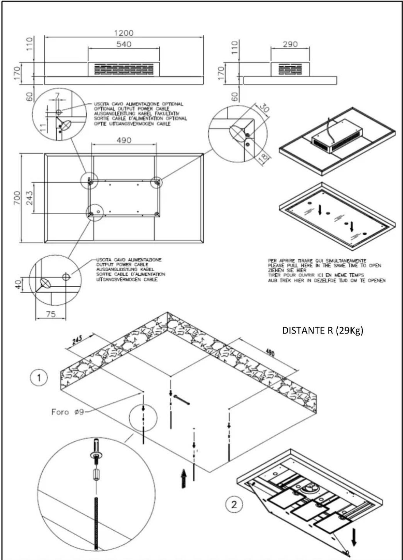
DISTANTE R
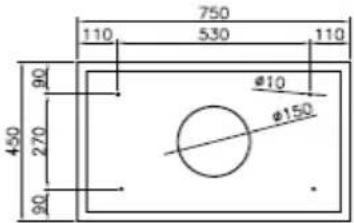
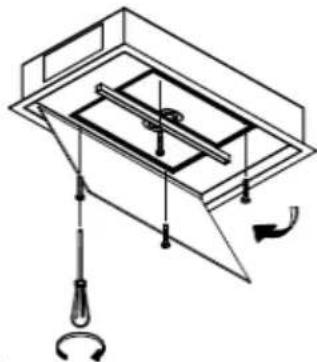
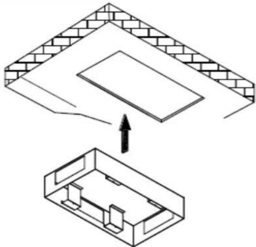
CEILING STRIPE 75/45 SM
CEILING STRIPE 75/45 SM (17Kg)
natural_image
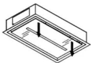
Isometric line drawing of a rectangular frame with internal parallel lines and two vertical arrows indicating direction (no text or symbols)Per aprire tirare qui simultaneamente
Please pull here in the same time to open
Zlehen sie hier
Pull ici pour ouvrir
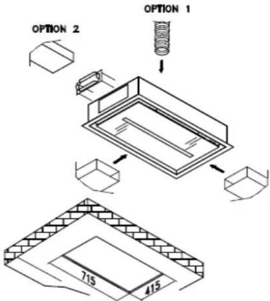
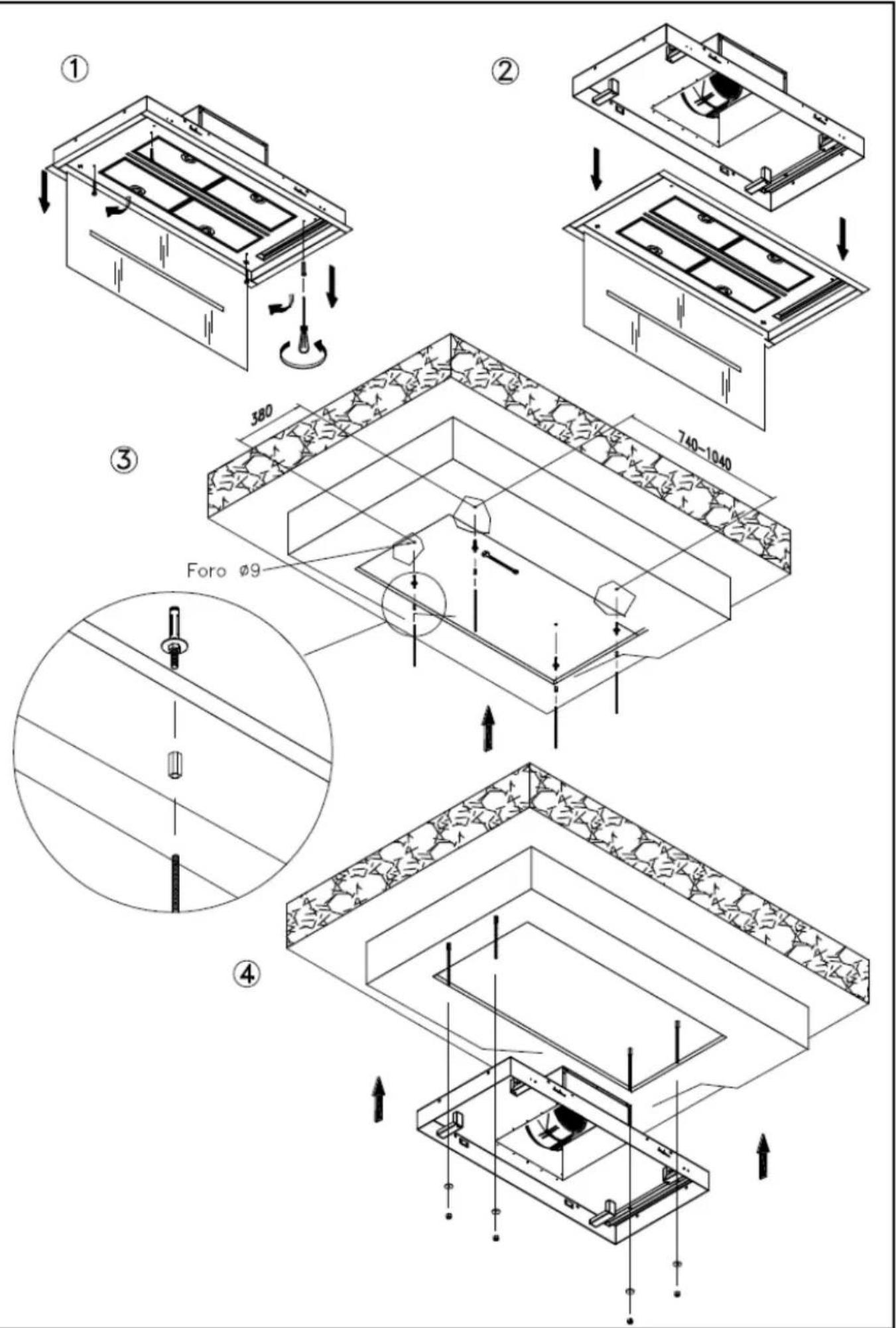
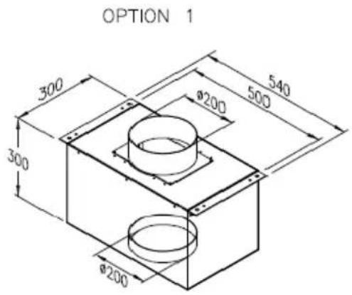
OPTION 1
①
natural_image
Technical line drawing of a mechanical assembly with no visible text or symbols②
natural_image
Isometric diagram showing a brick wall section being lifted into a smaller rectangular housing (no text or symbols)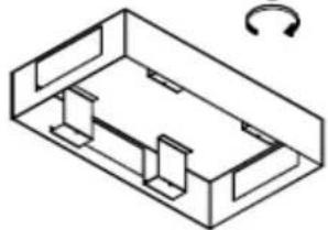
natural_image
Isometric line drawing of a rectangular electronic or mechanical housing with internal compartments and a curved arrow indicating rotation (no text or symbols)③
natural_image
Technical line drawing of a structural assembly with brick walls and internal components, no text or symbols present④
natural_image
Technical diagram of a mechanical assembly with no visible text or symbols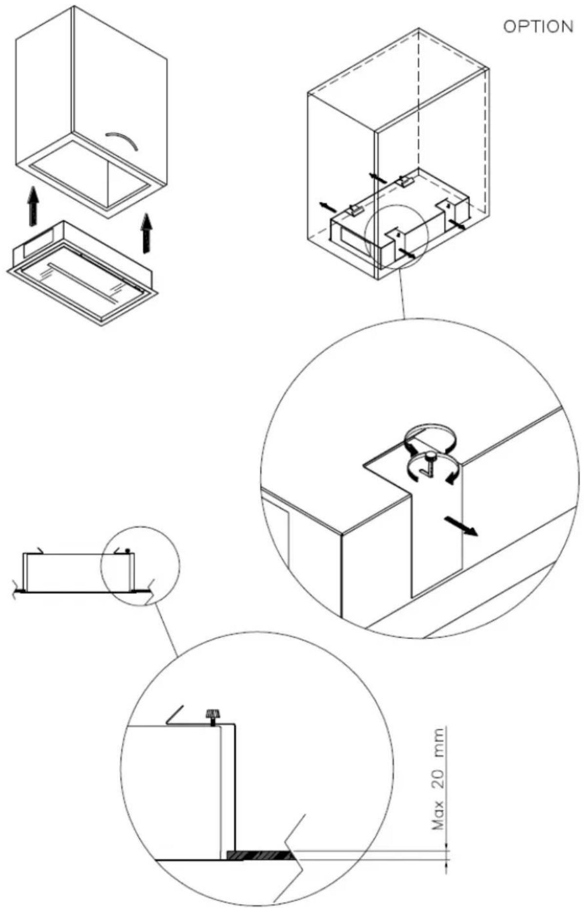
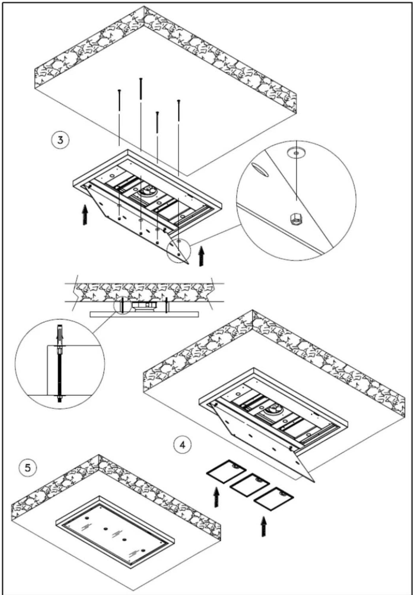
CEILING STRIPE 75/45
CEILING STRIPE 75/45 (21Kg)
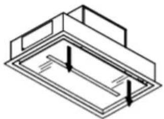
natural_image
Isometric line drawing of a rectangular frame with internal horizontal lines and two vertical arrows indicating direction (no text or symbols)Per aprire tirare qui simultaneamente
Please pull here in the same time to open
Ziehen sie hier
Pull ici pour ouvrir
OPTION 1
①
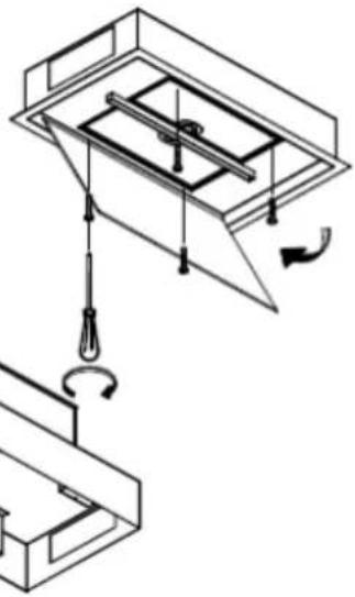
natural_image
Pure mechanical diagram showing a lifting mechanism with pulleys and rotating components (no text or symbols)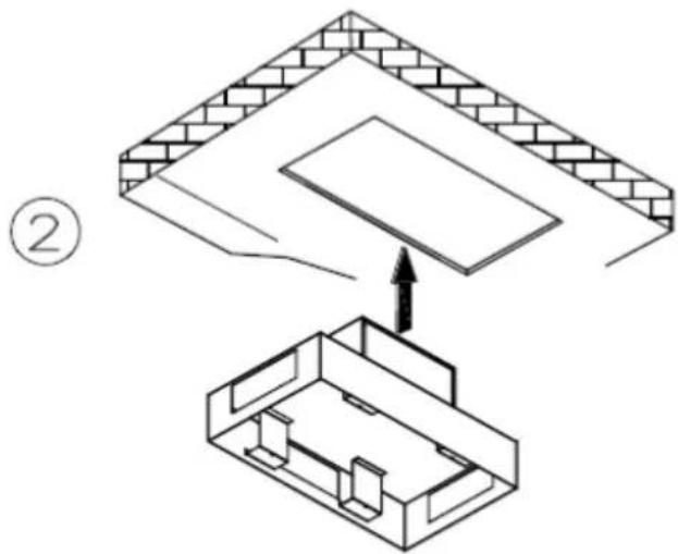
natural_image
Isometric diagram showing a brick wall section being lifted by an upward arrow into a 3D architectural structure (no text or symbols)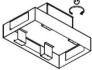
natural_image
Isometric line drawing of a mechanical housing or enclosure with internal components and a curved arrow indicating rotation (no text or symbols)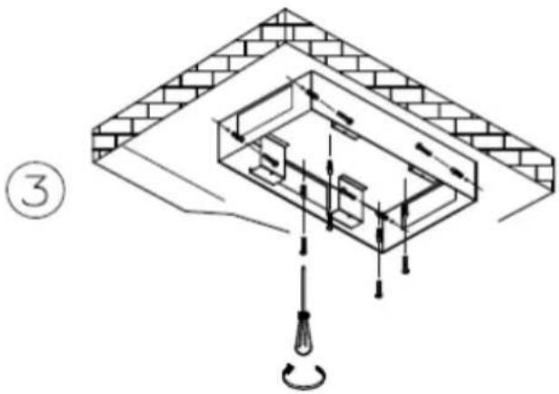
④
natural_image
Architectural diagram showing structural components with arrows indicating movement or force (no text or labels)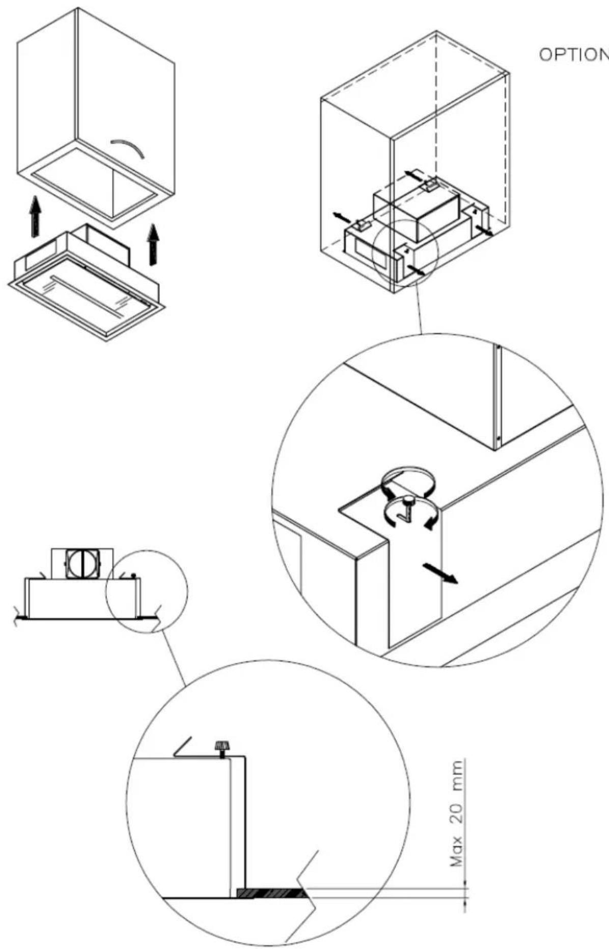
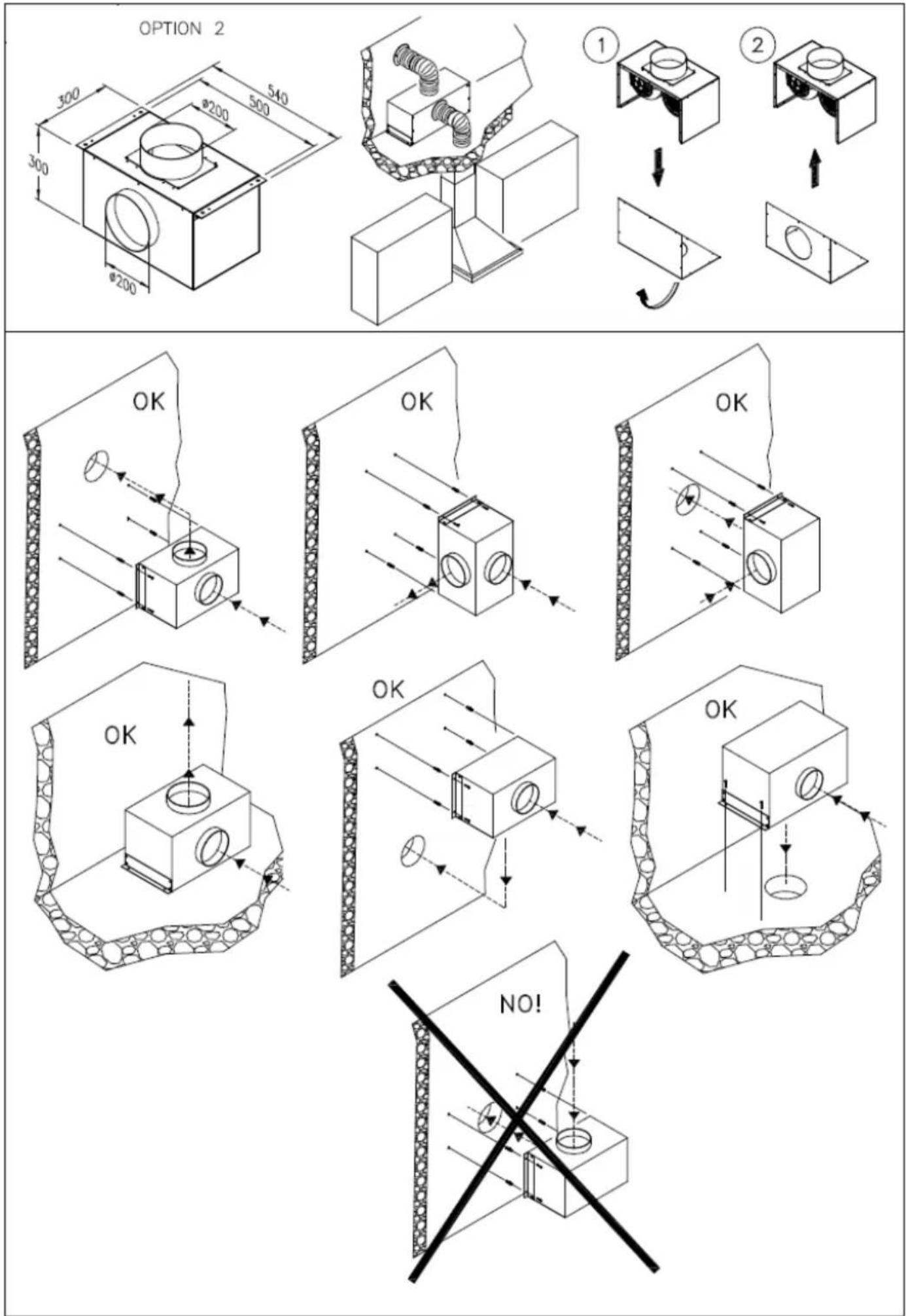
OPTION 2
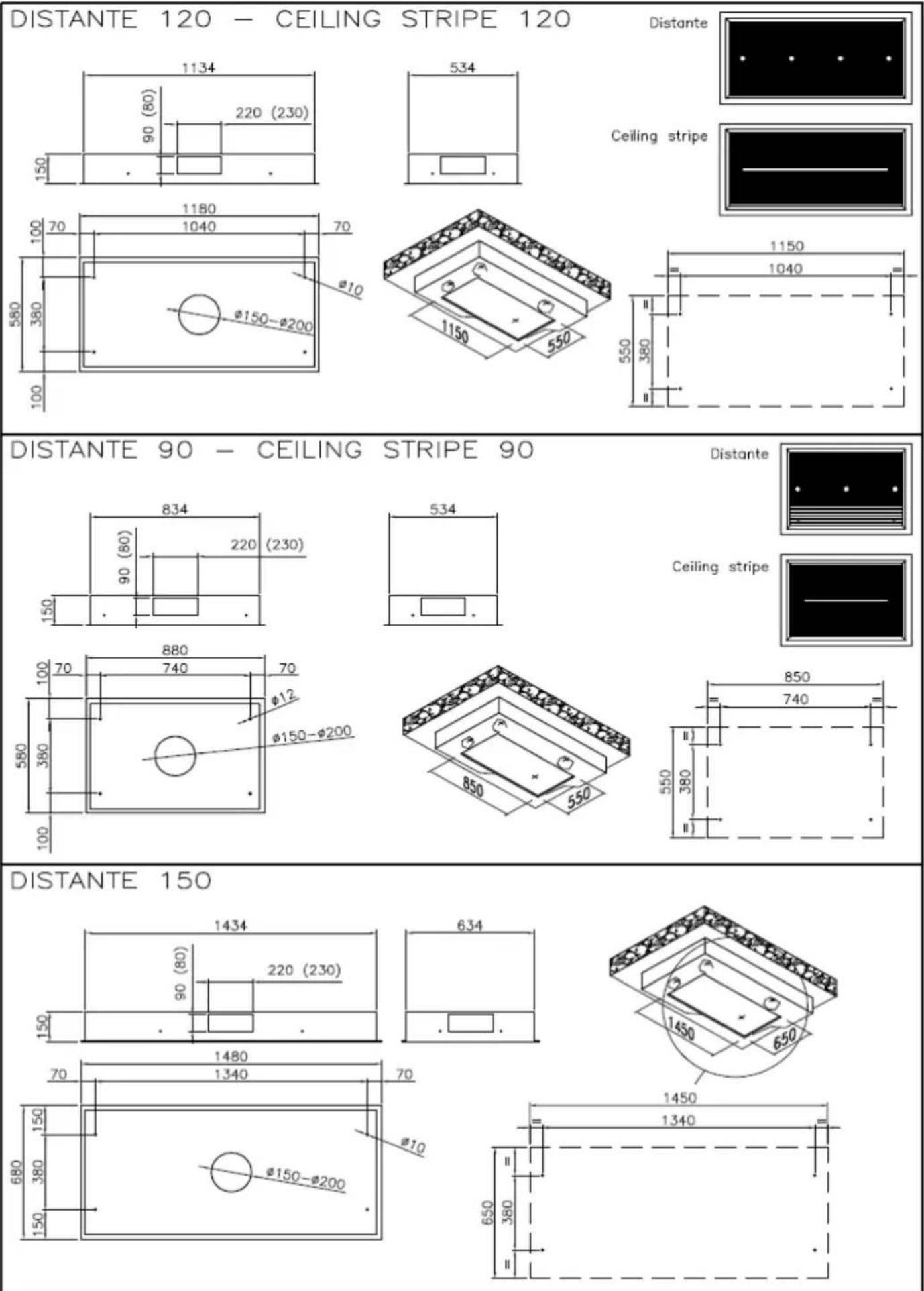
DISTANTE 90 - DISTANTE 120 - CEILING STRIPE 90 - CEILING STRIPE 120
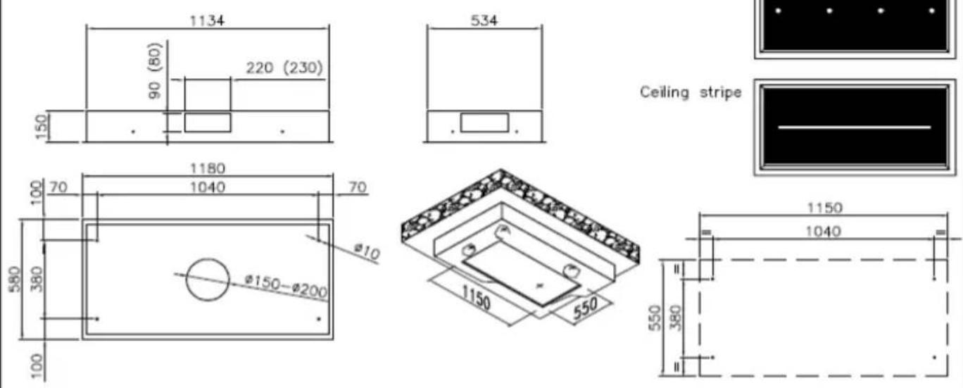
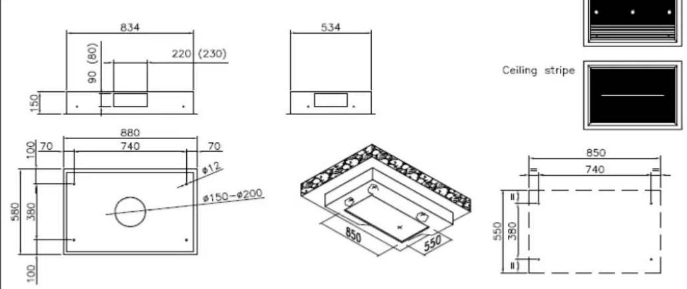
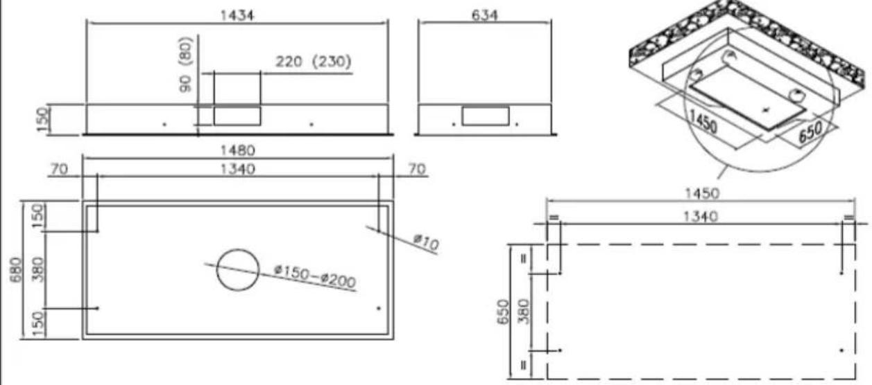
CEILING STRIPE 90 - 120
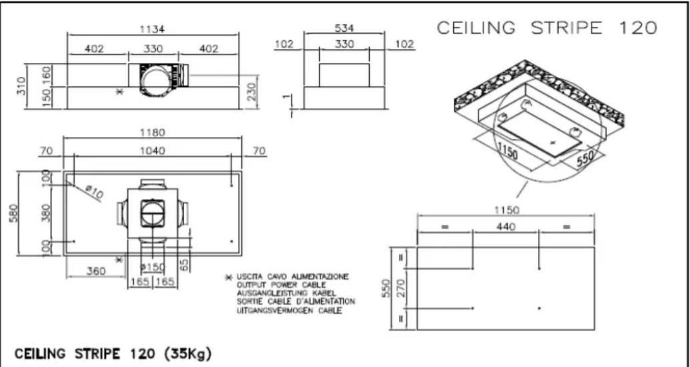
* USCITA CAVO ALIMENTAZIONE OUTPUT POWER CABLE AUSGANGLEISTUNG KABEL SORTIE CABLE D'ALIMENTATION UITGANGSVERMOGEN CABLE
CEILING STRIPE 90
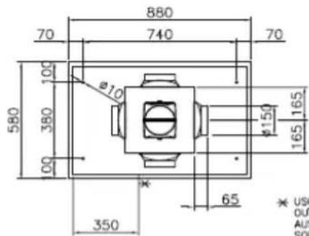
* USCITA CAVO ALIMENTAZIONE OUTPUT POWER CABLE AUSGANGLEISTUNG KABEL SORTIE CABLE D'ALIMENTATION UITGANGSVERMOGEN CABLE
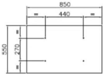
CEILING STRIPE 90 (24kg)
natural_image
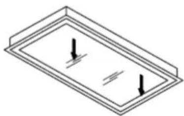
Isometric diagram of a rectangular frame with two downward-pointing arrows indicating forces or pressure, no text or symbols present.Per aprire tirare qui simultaneamente Please pull here in the same time to open Ziehen sle hier
CEILING STRIPE R 90
CEILING STRIPE R 120
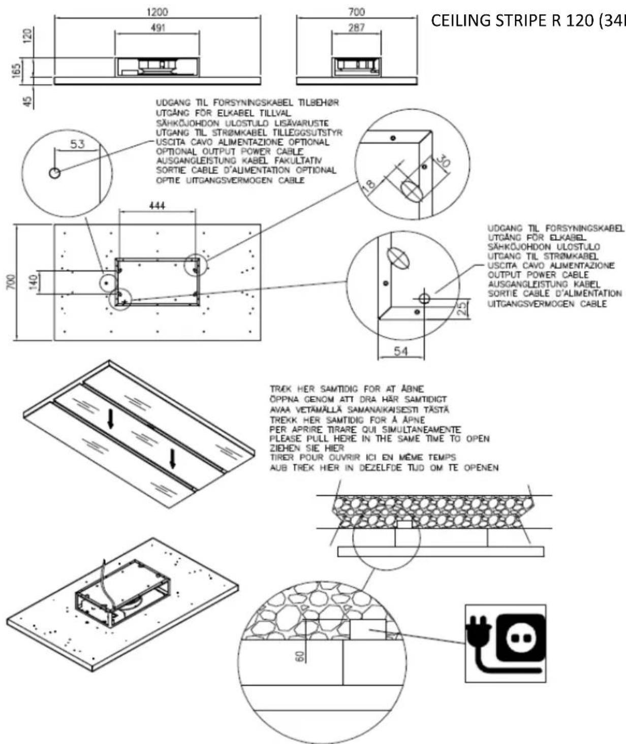
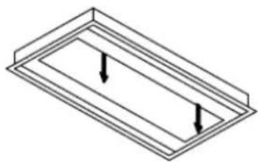
TREK HER SAMTIDIG FOR AT ABNE
ÖPPNA GENOM ATT DRA HÄR SAMTIDIGT
AVAA VETAMÄLLÄ SAMANA/KAISESTI TÄSTÄ
TREKK HER SAMTIDIG FOR A ÄPNE
PER APRIRE TIRARE QUI SIMULTANEMENTE
PLEASE PULL HERE IT THE SAME TIME TO OPEN
ZIEHEN SIE HIER
TIRER POUR OUVRIR ICI EN MÈME TEMPS
AUB TREK HIER IN DEZELFDE TÜD OM TE OPENEN
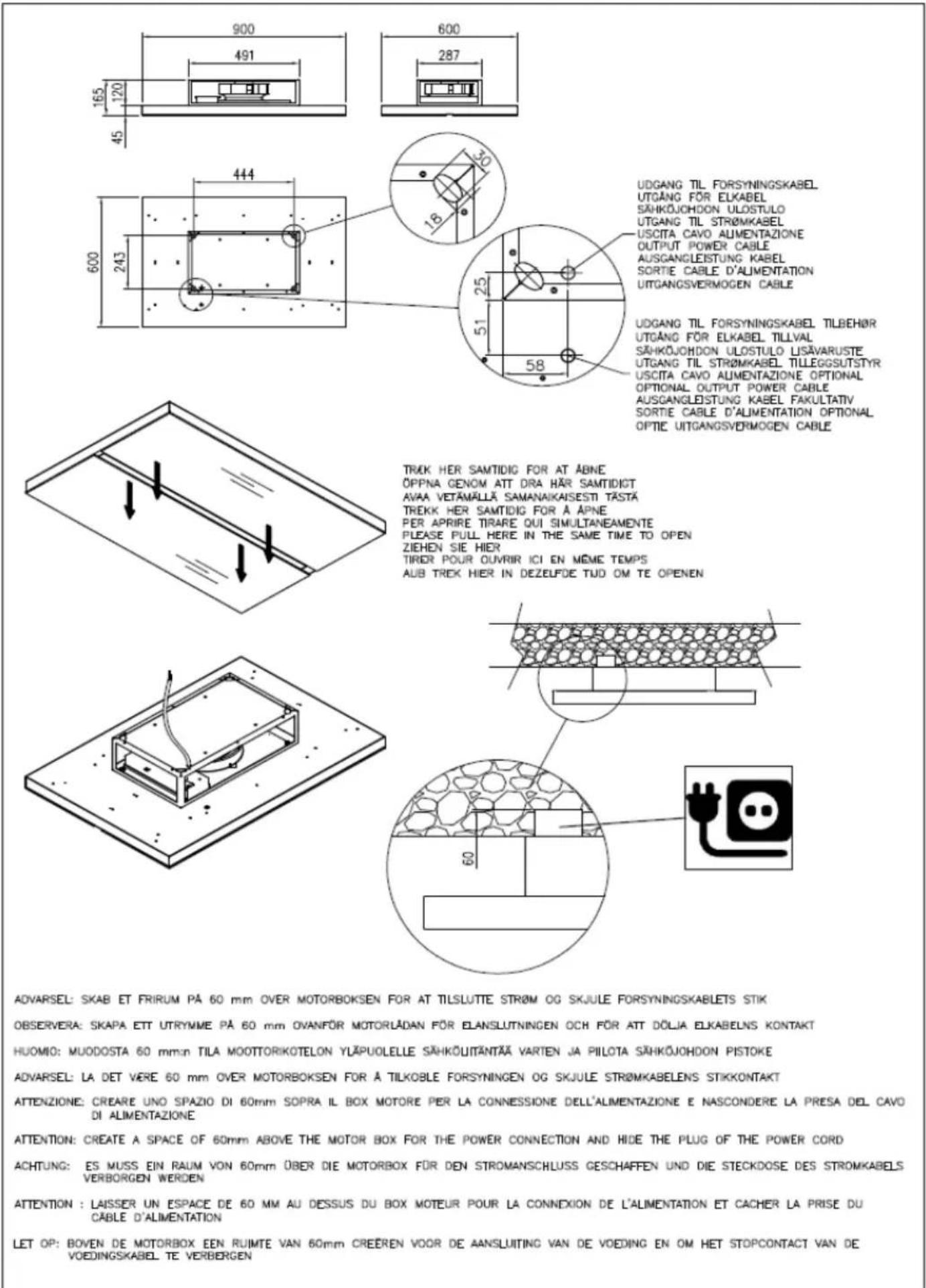
ADVARSEL: SKAB ET FRIRUM PÅ 60 mm OVER MOTORBOKSEN FOR AT TILSLUTTE STR∅M OG SKJULE FORSYNINGSKABLETS STIK
OBSERVERA: SKAPA ETT UTRYMME PÅ 60 mm OVANFÖR MOTORLÅDAN FÖR ELANSLUTNINGEN OCH FÖR ATT DÖLJA ELKABELNS KONTAKT
HUOMIO: MUODOSTA 60 mmn TILA MOOTTORIKOTELON YLÄPUOLELLE SÄHKÖLIITÄNTÄÄ VARTEN JA PILOTA SÄHKÖJOHDON PISTOKE
ADVARSEL: LA DET VERE 60 mm OVER MOTORBOKSEN FOR A TILKOBLE FORSYNINGEN OG SKJULE STRÖMKABELENS STIKKONTAKT
ATTENZIONE: CREARE UNO SPAZIO DI 60mm SOPRA IL BOX MOTORE PER LA CONNESSIONE DELL'ALIMENTAZIONE E NASCONDERE LA PRESA DEL CAVO DI ALIMENTAZIONE
ATTENTION: CREATE A SPACE OF 80mm ABOVE THE MOTOR BOX FOR THE POWER CONNECTION AND HIDE THE PLUG OF THE POWER CORD
ACHTUNG: ES MUSS EIN RAUM VON 60mm ÜBER DIE MOTORBOX FÜR DEN STROMANSCHLUSS GESCHAFFEN UND DIE STECKDOSE DES STROMKABELS VERBORGEN WERDEN
ATTENTION : LAISSER UN ESPACE DE 60 MM AU DESSUS DU BOX MOTEUR POUR LA CONNEXION DE L'ALIMENTATION ET CACHER LA PRISE DU CÂBLE D'ALIMENTATION
LET OP: BOVEN DE MOTORBOX EEN RUIMTE VAN 60mm CREEREN VOOR DE AANSLUITING VAN DE VOEDING EN OM HET STOPCONTACT VAN DE VOEDINGSKABEL TE VERBERGEN
CEILING PANEL 124

* USCITA CAVO ALIMENTAZIONE
OUTPUT POWER CABLE
AUSGANGLESTUNG KABEL
SORTIE CABLE D'ALIMENTATION
UITGANGSVERMOGEN CABLE
CEILING PANEL 124 22Kg
natural_image
Isometric diagram of a rectangular frame with two downward arrows indicating internal flow or movement (no text or symbols)Per aprire tirare qu' simultaneamente Please pull here in the same time to open Ziehen sie hier
natural_image
Technical line drawing of a mechanical housing or enclosure with internal compartments and mounting brackets (no text or symbols)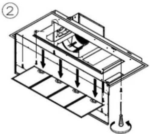
natural_image
Technical line drawing of a mechanical assembly with internal components and directional arrows (no text or symbols)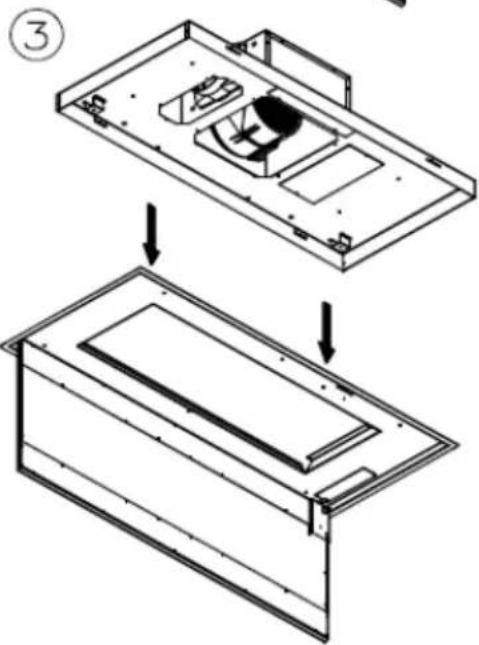
natural_image
Technical line drawing of a device interior showing two views: top view with internal compartments and bottom view with a recessed panel (no text or symbols)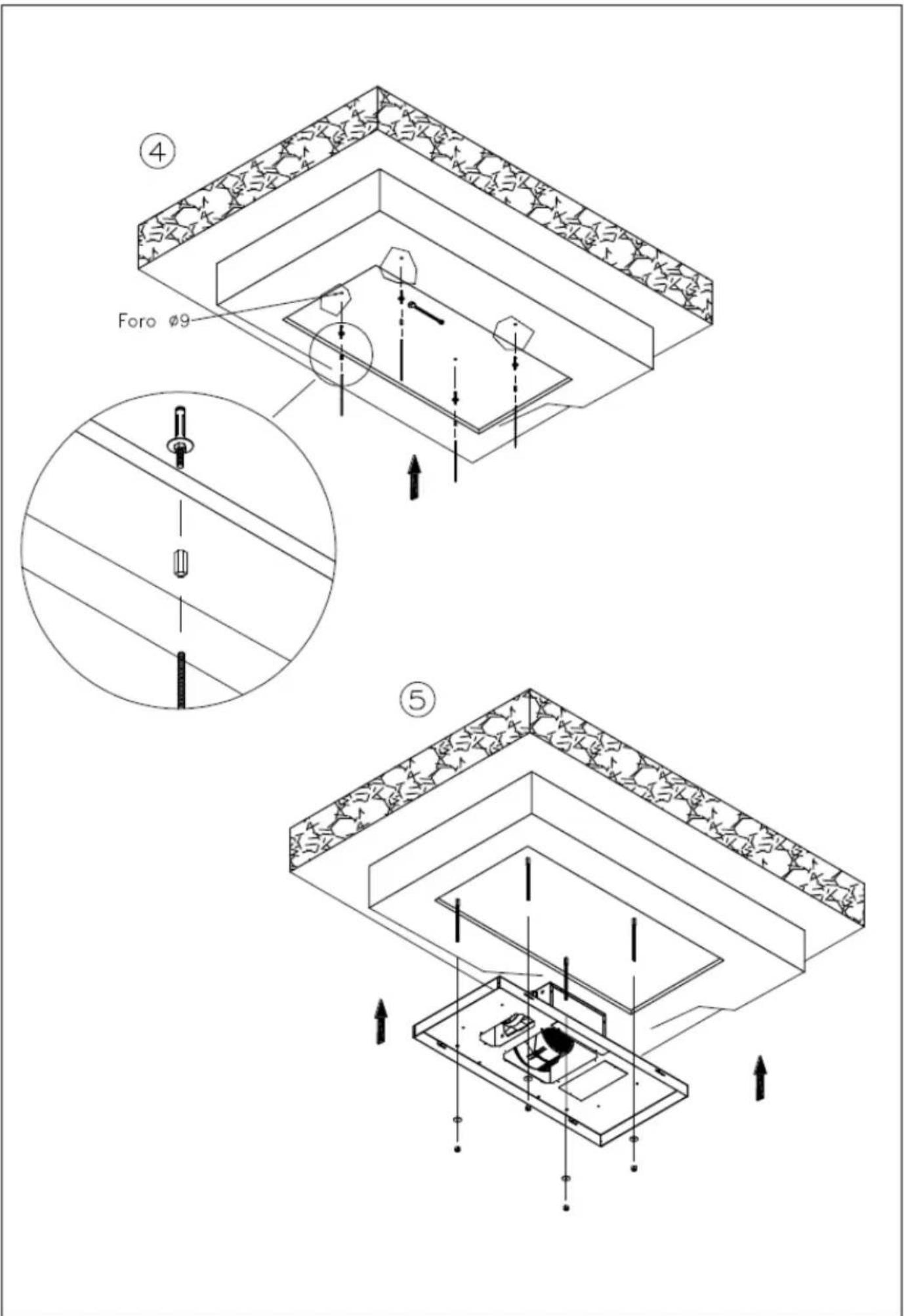
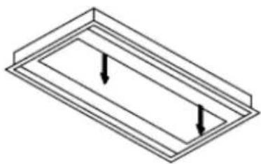
CEILING PANEL 124 SM
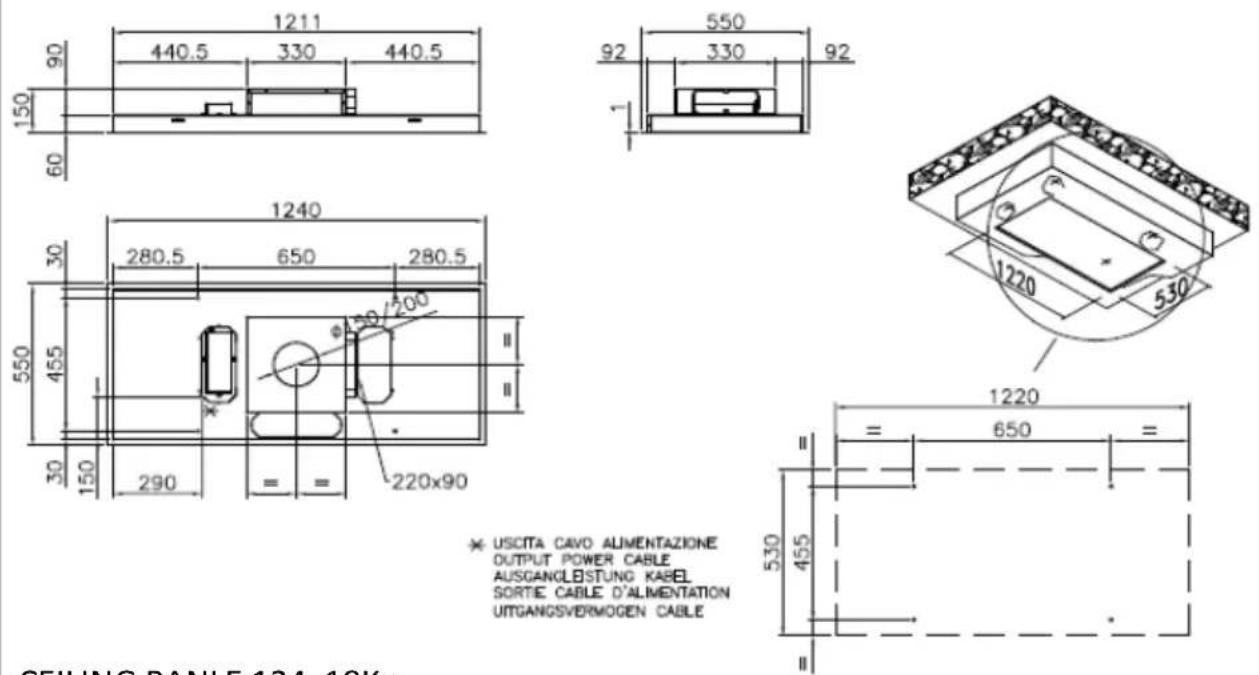
※ USCITA CAVO ALIMENTAZIONE OUTPUT POWER CABLE AUSGANGLESTUNG KABEL SORTIE CABLE D'ALIMENTATION UITGANGSVERMOGEN CABLE
CEILING PANLE 124 18Kg
natural_image
Isometric diagram of a rectangular frame with two downward arrows indicating internal flow or force (no text or symbols)Per aprire tirare qu' simultaneamente Please pull here in the same time to open Ziehen sie hier
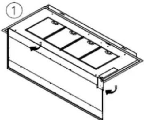
natural_image
Technical line drawing of a rectangular enclosure with internal compartments and ventilation ducts (no text or symbols)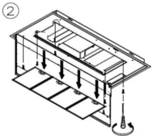
natural_image
Technical diagram of a mechanical assembly with downward force arrows and a rotating knob (no text or symbols)
natural_image
Technical line drawing showing two views of a device casing with internal compartments and mounting points (no text or symbols)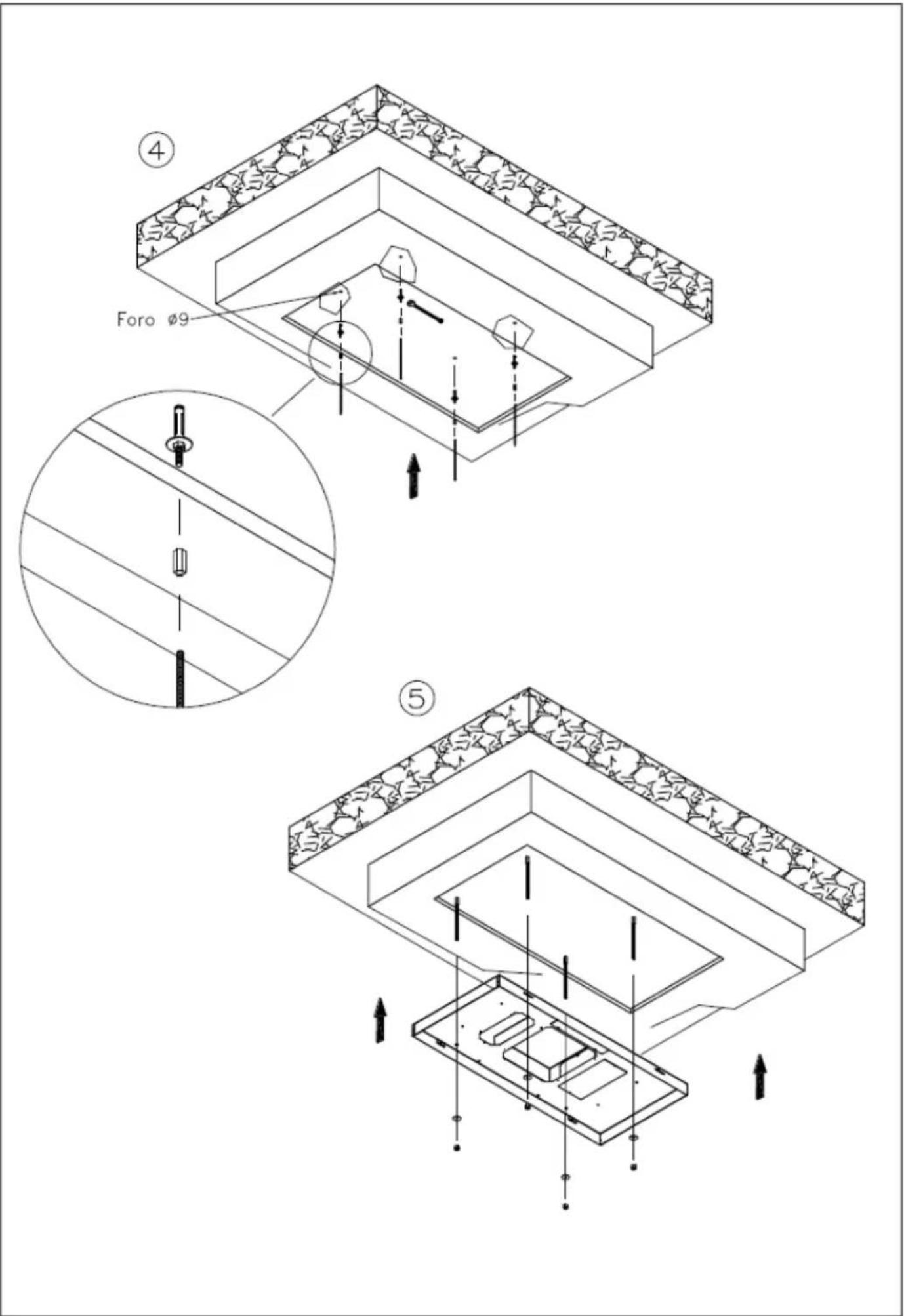
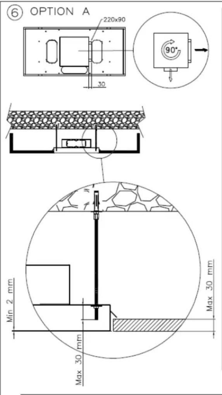
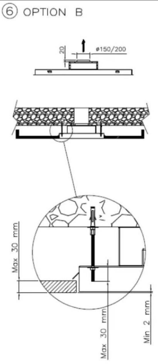
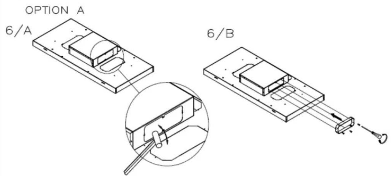
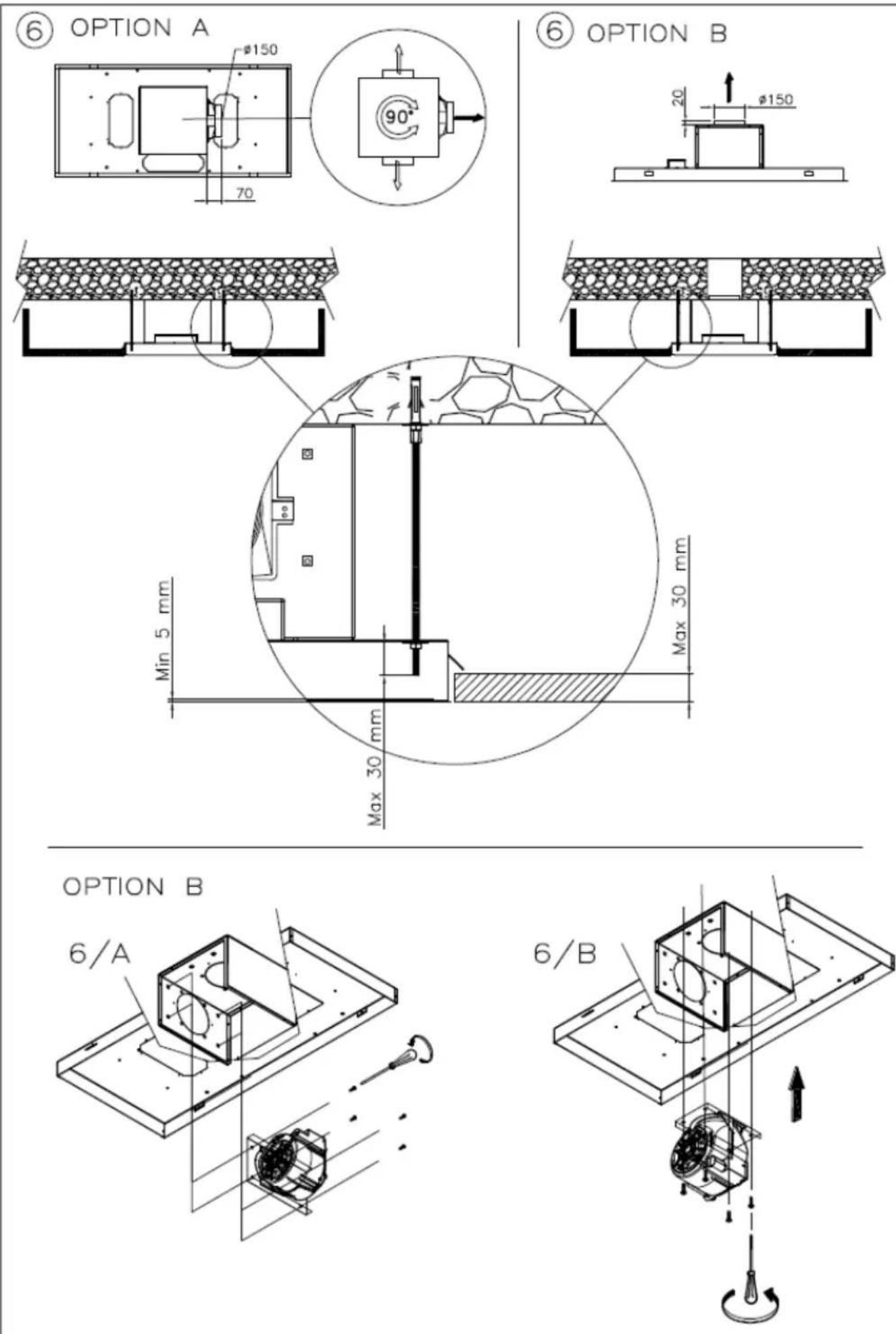
OPTION B
6/A
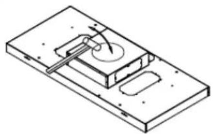
natural_image
Isometric technical drawing of a mechanical assembly with no visible text or symbols6/B
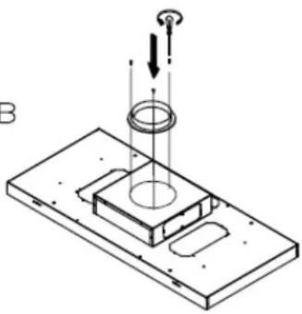
natural_image
Isometric technical diagram showing a mechanical assembly with a central circular component and two vertical rods, no text or symbols present.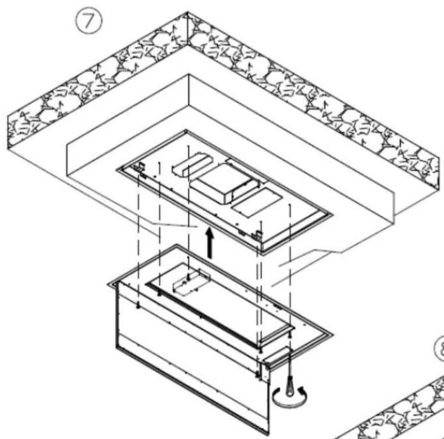
natural_image
Architectural cross-section diagram of a building showing roof, windows, and structural elements (no text or labels)EICOE22
* USCITA CAVO ALIMENTAZIONE
OUTPUT POWER CABLE
AUSGANGLEISTUNG KABEL
SORTIE CABLE D'ALIMENTATION
UITGANGSVERMOGEN CABLE
× USCITA CAVO ALIMENTAZIONE OUTPUT POWER CABLE AUSGANGLEISTUNG KABEL SORTIE CABLE D'ALIMENTATION UITGANGSVERMOGEN CABLE
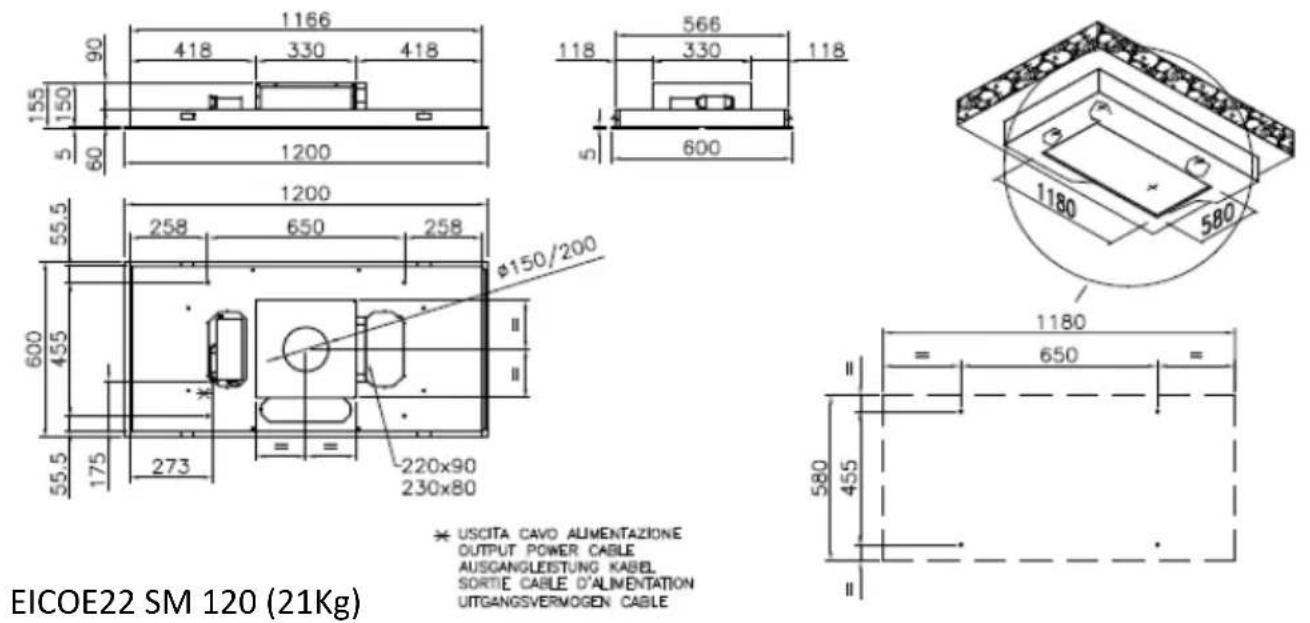
EICOE22 SM
* USCITA CAVO ALIMENTAZIONE
OUTPUT POWER CABLE
AUSGANGLEISTUNG KABEL
SORTIE CABLE D'ALIMENTATION
UITGANGSVERMOGEN CABLE
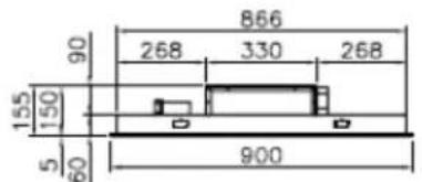
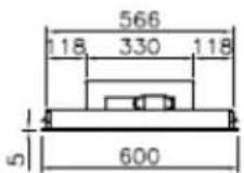
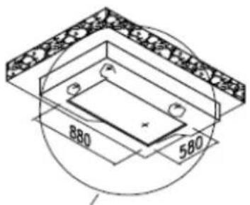
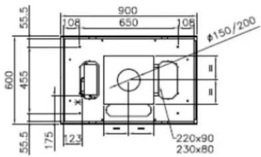
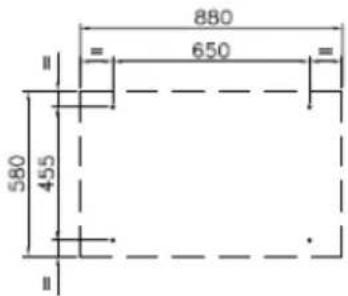
EICOE22 SM 90 (16Kg)
× USCITA CAVO ALIMENTAZIONE
OUTPUT POWER CABLE
AUSGANGLEISTUNG KABEL
SORTIE CABLE D'ALIMENTATION
UITGANGSVERMOGEN CABLE
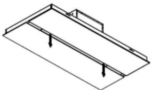
natural_image
Isometric line drawing of a structural beam with load arrows (no text or symbols)Per aprire tirare quì simultaneamente Please pull here in the same time to open Ziehen sie hier
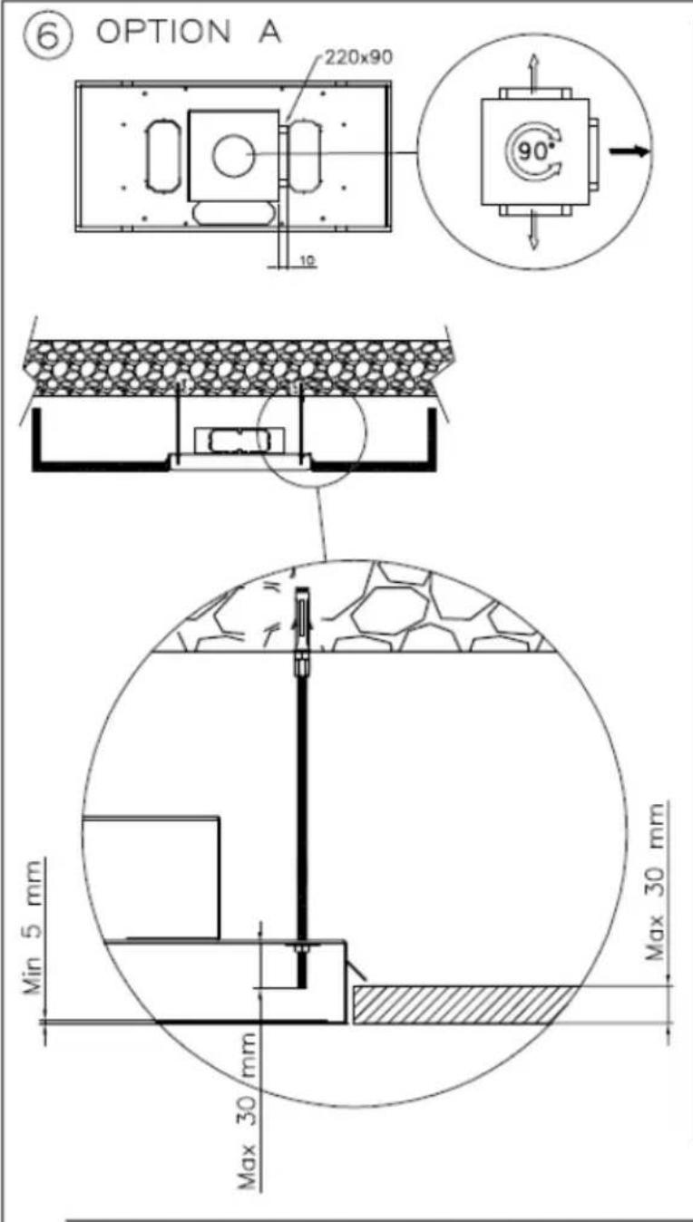
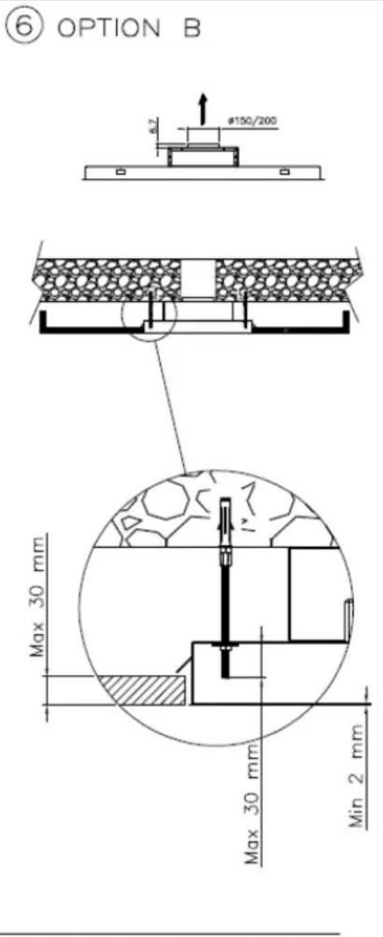
OPTION B
6/A
natural_image
Isometric technical drawing of a mechanical assembly with no visible text or symbols6/B
natural_image
Isometric technical diagram showing a mechanical assembly with a central component and a suspended ring (no text or symbols)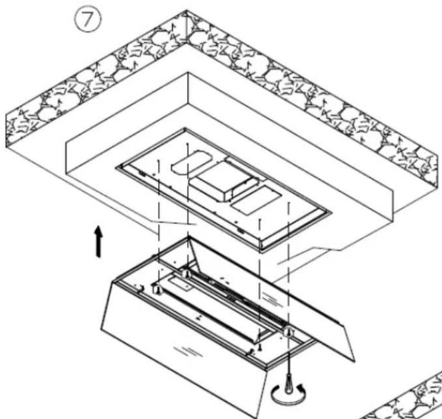
natural_image
Technical diagram of a mechanical assembly with layered components and directional arrows (no text or symbols)
AIDA SM
AIDA
AIDA 60 (10Kg)
AIDA 90 (11Kg)
natural_image
Technical line drawing of a mechanical component with arrows indicating force or movement (no text or symbols)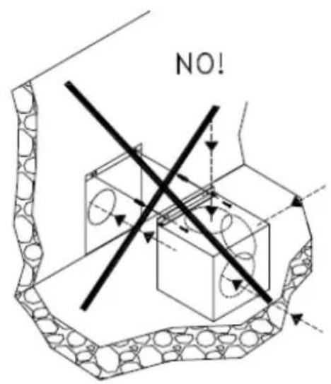
AMT10
AMT20
natural_image
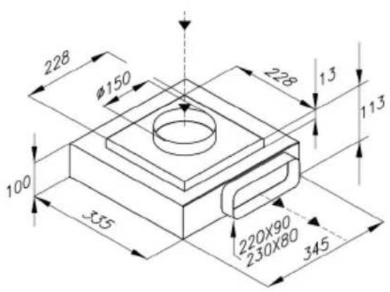
Technical line drawing of a mechanical assembly with a magnified inset showing internal components (no text or symbols)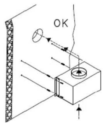
AMT13
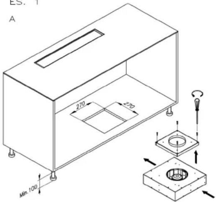
PLINTH EXSTERN MOTOR 1000
ES. 1
natural_image
Isometric technical diagram of a mechanical device with internal components and directional arrows (no text or labels)ES. 2
natural_image
Technical line drawing of a mechanical assembly with no visible text or symbols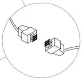
natural_image
Diagram of two connected 3D electrical connectors with pins, enclosed in a circle (no text or symbols)INDICE - INDEX:
ROMEO.... pg.39
HAMLET.... pg.43
DISTANTE R.... pg.47
CEILING STRIPE 75/45....pg.49
DISTANTE 90, DISTANTE 120, CEILING STRIPE 90 SM, CEILING STRIPE 120 SM....pg.53
CEILING STRIPE 90 - 120.... pg.56
CEILING STRIPE R 90.... pg.59
CEILING STRIPE R 120.... pg.62
CEILING PANLE 124.... pg.65
CEILING PANLE 124 SM.... pg.69
EICOE22....pg.73
EICOE22 SM....pg.77
AIDA SM.... pg.81
AIDA ...... pg.85
AMT09.... pg.87
AMT10.... pg.89
AMT20....pg.91
AMT13.... pg.93
PLINTH EXSTERN MOTOR 1000.... pg.94
eico
EICO AS
Östergade 118
9700 Brønderslev

- INSTRUCTIONS FOR USING, MAINTAINING AND INSTALLING THE HOOD
- WARNINGS
- INSTALLATION
- Hoods equipped for remote motors
- ASSEMBLY INSTRUCTIONS
- ELECTRIC WIRING
- CONTROLS
- KEYBOARD CONTROLS (Fig. 1)
- SOFT TOUCH CONTROL (Fig. 2)
- DIGITAL CONTROLS \ TOUCH CONTROLS (Fig. 3)
- RADIO-CONTROL (Fig. 4)
- Radio control
- ATTENTION:
- Control buttons:
- USE AND MAINTENANCE
- Changing the light bulbs
- Cleaning the metal filters:
- Carbon filters
- Condensation in the hood
- Cleaning the hood
- BEDIENUNGS-, WARTUNGS- UND INSTALLATIONSHANDBUCH ABZUGSHAUBE
- ROMEO
- HAMLET
- CEILING STRIPE 75/45 SM
- CEILING STRIPE 75/45
- CEILING PANEL 124
- CEILING PANEL 124 22Kg
- OPTION B
- EICOE22 SM
- AMT20
- INDICE - INDEX:
- eico
Brand : EICO
Model : Ceiling Stripe 120 W SM
Category : Range hood