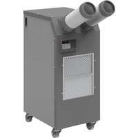
HWC-19R - Air Conditioning Airrex - Free user manual and instructions
Find the device manual for free HWC-19R Airrex in PDF.


| Brand | Airrex |
| Model | HWC-19R |
| Category | Mobile monobloc air conditioner |
| Minimum room area | 3.07 m² |
| Ventilation airflow rate | 50.7 m³/h |
| Refrigerant | Flammable type A2L |
| Power supply | 220-240 V ~ 50 Hz |
| Power consumption | 800 W (estimate) |
| Cooling capacity | 7000 BTU/h (estimate) |
| Dimensions (L x H x D) | 30 x 40 x 50 cm (estimate) |
| Net weight | 15 kg (estimate) |
| Main functions | Cooling, dehumidification, ventilation |
| Noise level | 55 dB(A) (estimate) |
| Water tank capacity | 1.5 L (estimate) |
| Filter type | Washable air filter |
| Maintenance | Clean filter every 2 weeks |
| Safety | Refrigerant leak detection, automatic shutoff |
| Warranty | 1 year |
Frequently Asked Questions - HWC-19R Airrex
User questions about HWC-19R Airrex
0 question about this device. Answer the ones you know or ask your own.
Ask a new question about this device
Download the instructions for your Air Conditioning in PDF format for free! Find your manual HWC-19R - Airrex and take your electronic device back in hand. On this page are published all the documents necessary for the use of your device. HWC-19R by Airrex.
USER MANUAL HWC-19R Airrex
natural_image
Exterior view of a BIRRCX air conditioning unit with two cylindrical pipes and control panel (no visible text or symbols)Thank you for purchasing the unit. Before operation, please read this user's manual carefully.
▶ You can find the user manuals for all our products online.
TABLE OF CONTENTS
SAFETY INSTRUCTIONS 3
PRECAUTIONS FOR USE 4
EXTERIOR DESCRIPTION 5 \~ 6
SPECIFICATIONS 7
CONTROL PANEL FUNCTIONS 8 \~ 9
MODE CHANGING METHOD 10
HOW TO SET THE 'OFF' TIMER 11
'ERROR' and WARNING INDICATORS 14
ECONOMY MODE 15
TROUBLE SHOOTING 15
CLEANING AND MAINTENANCE 16
HOW TO INSTALL & PRECAUTIONS 17 \~ 18
ACCESSORIES 19
THE INSTALLATION, SERVICE AND OPERATION MANUAL 20 \~ 29
This appliance is not intended for use by persons (including children) with reduced physical, sensory or mental capabilities, or lack of experience and knowledge, unless they have been given supervision or instruction concerning use of the appliance by a person responsible for their safety.
Children should be supervised to ensure that they do not play with the appliance.
It is essential that you read 'SAFETY INSTRUCTIONS' carefully before use and follow them at all times.
▶ Keep this manual on hand for reference.
This unit is specified for use on the rated voltage power supply.
The warranty form is on the last page. Please complete it now and keep it in a safe place.
We have a policy of continual improving on our products. The contents (features and specifications) in this manual are therefore subject to change without notice.
These are contents for keeping the safety and preventing the property damage. Please read and use correctly.
- Precautions on this page are for the safe and correct use of the unit and for the preventing a danger and damage of the operator or others. With regard to the contents, these are classified into

WARNING
This is the content that when a faulty handling is done, a person's death or heavy injury is expected.

CAUTION
This is the content that when a faulty handling is done, a person's injury or property damage is expected.
The following symbols are for your guidance :

You must NOT. You MUST.

WARNING
As for a damage that occurs during non-keeping the following cautions, the manufacturing company cannot be responsible for the compensation.

Use an outlet for exclusive use of alternative current 115 V\~. (A fire or electric shock may be caused.)

After wiping out dusts from the power plug, insert it correctly into outlet. (Due to electric shock or short, a smoking or fire may happen.)

Do not use a damaged electric cord, plug or loosened outlet. (An electric shock, short or fire may be caused.)

Use a rated capacity fuse. (A trouble or fire may be caused.)

Do not pull out the cord or touch the power plug with a wet hand. (An electric shock, fire may be caused.)

Do not forcibly bend the cable or press by a heavy thing for not being damaged. (Electric shock or fire may be caused.)

Do not connect or extend a power cord in the middle of it. (An electric shock, fire may be caused.)

Insert a cord into the outlet with earthed terminal. (In case of common outlet, set a separate earth terminal without fail.)

When cleaning, pull out the plug without fail. (An electric shock may be caused.)

When water supply is stopped or leaked, do not operate the unit.

Do not connect to other power outlet or home appliance by using extension cord.

Do not randomly disassemble or remodel the product. (A trouble, electric shock, or fire may be caused.)

Do not insert a finger or stick into blowing hole. Hurt may be caused, so give a warning to children.

In case of a strange sound or smell in the air conditioner, stop the operation and cut off the power, and contact the Service Center. (A continuous operation in abnormal condition, a trouble, electric shock, fire may be caused.)

Use tap water pressure.

If the supply cord is damaged, it must be replaced by the manufacturer, its service agent or similarly qualified persons in order to avoid a hazard.

CAUTION
For the damage occurred due to non-keeping of following matters, the manufacturer is not responsible for the compensation.

Do not install the product on the uneven or slant place.

In case of thunder, lightning or no-operation for a long time, pull the power plug out of the outlet. (Electric shock, leakage or fire may be caused.)

For safekeeping, avoid hot, humid place, and keep it in dry indoor place. (Rusting or trouble may be caused.)

When inserting/ pulling out the power plug, grip the plug. (A fire may be caused by electric shock or short-circuit.)

In case of power cord's damage, contact A/S Center for changing it. (Electric shock or fire may be caused.)

Do not spray water on to the cooler nor use solvents such as benzene, thinner or alcohol for cleaning. (There is a risk of electric shock and / or short circuit)

Do not step on the product or put a thing on it. (Trouble or electric shock may be caused.)

Excessive cold wind may be harmful to health.

During operation, do not pull the water supply hose or the drain hose. Water leakage or fire damage may be caused.

Do correctly the grounding device work without fail. However, do not connect to the gas pipe, water pipe or telephone line. (If the grounding device is not set, a trouble or electric shock may be caused.)

For preventing water leakage, close the water supply valve.
• After reading carefully, keep it where any user may see it anytime.
- Rated voltage of this product is 115 V\~, 60 Hz, 1 Ph. Connect to the rated power source and the earthed outlet.
- Make sure of the safety of the place to be used.
- Do not touch the power cord with a wet hand.
- When moving this product, do not lean more than 30^ or topple it. (When operating, keep it horizontal, or in unavoidable situation, keep it less than 2^ .)
- Do the exclusive power circuit for the air conditioner.
- Do not pull the power cord. (If the power cord is damaged, a fire or electric shock may be caused.)
- Use the standardized fuse without fail.
- Operate efficiently the unit under the shadow, and avoid operation in the temperature higher than 113^ .
- Keep space more than 20 inch around the air-intake so that a smooth in-taking of air can be done.
- As dust in the filter or the heat-exchanger deterior at the cooling, do clean the filter of the heat-exchanger regularly.
- When using the product, use it indoor place free from direct sunlight.
- Do not use this product as a means of moving other heavy goods or as a carrier of man.
- Do not insert any foreign substance (can, bottle of drink) into cold air discharge hole. It may damage the product.
- Do not put an obstacle in front of the air-intake hole. (Trouble may be caused.)
- The optimum distance between the worker and the discharge duct is less than 80 inch.
- When use, fix the locking device of front wheel at ON. (For release, press OFF.)
- Do not use it, when water supply is stopped. (When water stoppage, re-operating is possible up to 2 times, and in case of water stoppage or shortage, the error E1 is shown and the operation will be stopped.)
- If the water supply is low, the product cannot be normally operated, and main parts may be damaged.
- Discharged water is in state that removed indoor heat is added to the pure tap water, thus the waste heat can be re-used for other purpose. (But, it cannot be used as drinking water.)
● FRONT VIEW
- For the efficient improvement of this product, the specification may be changed without prior notice.
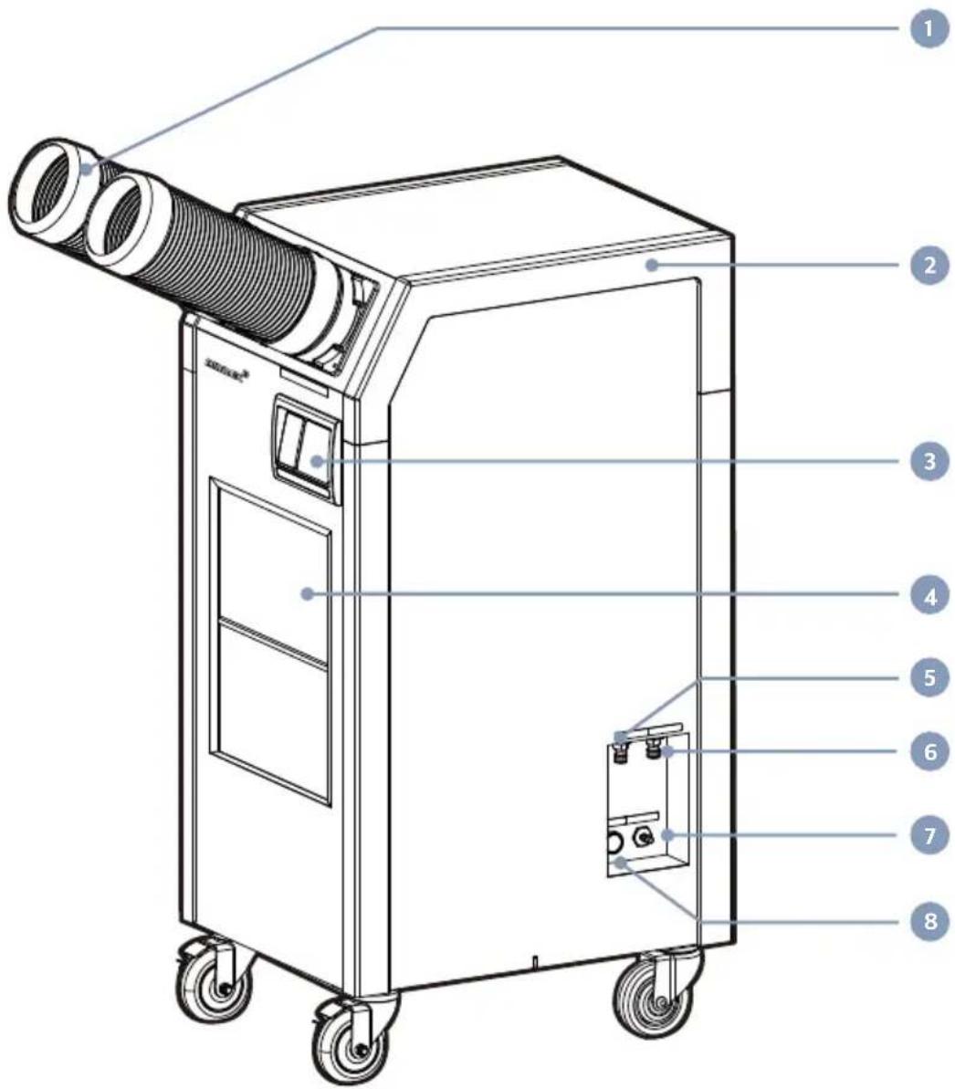
1 Discharge Duct
(The place where cold air comes out.)
3 Digital Controller
5 Connecting hole for supplying water (The place where water is supplied to the heat-exchanger.)
7 Drainage of condensed water (The place where condensed water collected in the drain pump installed inside is drained.)
2 Bumper
4 Air intake hole (Evaporator)
Indoor unit / Filter
(The place where indoor air enters.)
6 Connecting hole for discharging water (The place where water of the heat-exchanger is discharged.)
8 Pump Button
EXTERIOR DESCRIPTION
● BACK & SIDE VIEW
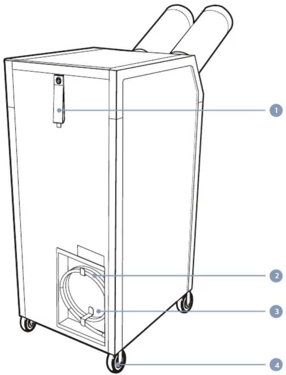
1
2 Power CordCord & Hose Hangers
3
Electrical panel (The place where electrical control panel is installed inside.)
4
Casters
| MODEL HWC-19R | ||||
| Cooling Capacity | Btu/h(W) | 18,200(5,300) | ||
| Power Supply - 115 V~, 60 Hz, 1 Ph | ||||
| PowerConsumption | kW 1.4 | |||
| CurrentConsumption | A 11.7 | |||
| Dehumidification | Max. gal/day 13 | |||
| Nom. | gal/day 9 | |||
| Refrigerant(R-454B) | Ibs 1.1 | |||
| Dimensions(W x D x H) | inch 18 x 23 x 43 | |||
| Weight Ibs 163 | ||||
| Operating Conditions 65 ~ 118°F (18 ~ 48°C) | ||||
| Condenser Water Flow | 60°F Water In | 1.11 GPM | ||
| 85°F Water In | 4.51 GPM | |||
| Water Pressure | Max. | 80 psi | ||
| Min. | 40 psi | |||
| Power Cord | LCDI 5-15 | |||
CONTROL PANEL FUNCTIONS
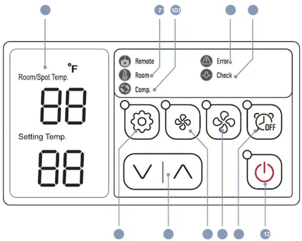
| NAME DESCRIPTION | ||
| 1 Power |  | Use to power on / off. |
| 2 V ∧ Button |  | Raises or lowers the setting temperature or sleep (off) time. |
| 3 Mode |  | Use to select Cooling / Fan / Dehumidification mode. |
| 4 Fan Low |  | Controls fan low speed. |
| 5 Fan High |  | Controls fan high speed. |
| 6 Off Timer |  | You can set the time to stop the unit. You can set 0~24 hours. Time intervals are 30 mins. up to 10 hours and then 1 hour between 10 and 24 hours. |
| 7 Room |  | If the LED is on, the displayed temperature is for room temp. |
| 8 Comp. |  | When the compressor is operating, the LED is on. |
| 9 Error | [K8xH] | Error signal. |
| 10 Check |  | If water is full or Align drain tank needs to be checked, the LED is on. |
| 11 Display | 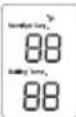 | Display room temperature, and also the setting temperature and sleep time if they had been set. |
MODE CHANGING METHOD
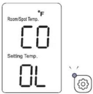
COOLING MODE
If you press the 'Mode' button. 'COOL' is displayed. Then LED is on.
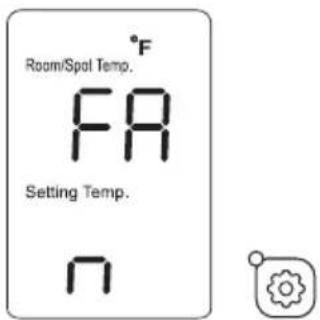
FAN MODE
If you press the 'Mode' button, when the cooling is operating, 'FAN' is displayed. Then LED is off.
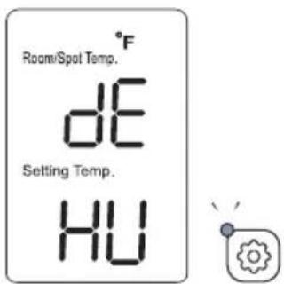
● DEHUMIDIFICATION MODE
If you press the 'Mode' button, when the fan is operating, 'dEHU' is displayed. Then LED is on.
This function enables you to set the length of time you want the unit to operate.
STEP 1
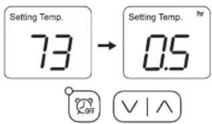
- When unit is operating, press the 'Off Timer' button and set the length of time you want by pressing ∧ or ∨. Each time you press the button you will increase the 'time to off' period by 30 mins. up to 10 hours, and 1 hour up to 24 hours. The display will show 0.5 for 30 min and 1 for an hour. One and a half hours will show 1.5.
STEP 2
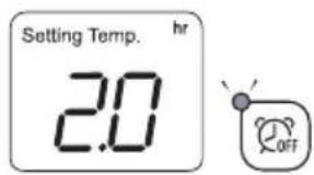
- When you have finished setting the time period, the 'Off Timer' lamp will be on which indicates the unit is in sleep (Off Timer) mode.
STEP 3
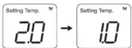
AFTER 1hr
- If you press the 'Off Timer' button during its operation, the remaining time will be shown.
CANCEL
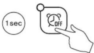
- To cancel 'Off Timer', press and hold 'Off Timer' button for 1 second. It will then switch the timer off automatically.
- When you turn ON, the setting temperature is displayed.
- You can change setting temperature.
• The display showing the set temperature will blink 3 times.
● Display Room Temperature Range & Setting Range.
COOLING MODE
| Mode | Display range | Setting range |
| Room | 32°F ~ 99°F | 64°F ~ 86°F |
| Spot | 34°F ~ 86°F |
Cooling operates when room temperature is higher than set temperature.
Cooling stops when room temperature is lower than set temperature.
- SPOT or ROOM MODE
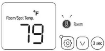
To change the temperature of the entire room, select 'Room mode'. For targeted cooling of machinery servers or people etc select
'Spot mode'. Applicable only when cooling mode.
- If you want to see room temperature, when unit is operated, push 'mode' and 'v' button simultaneously for 3 seconds.
• Light be on the 'Room LED' when room mode set.
- LOCK or UNLOCK
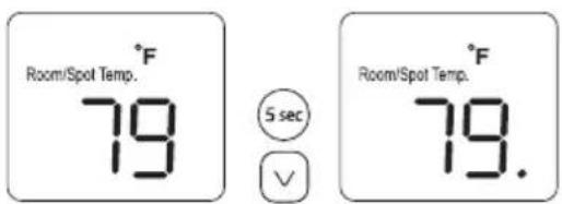
- If you press 'V' for 5 seconds when the unit is turned off, you can control 'LOCK, UNLOCK' mode.
- When You set 'LOCK' there will be a dot .' below the number in the screen.
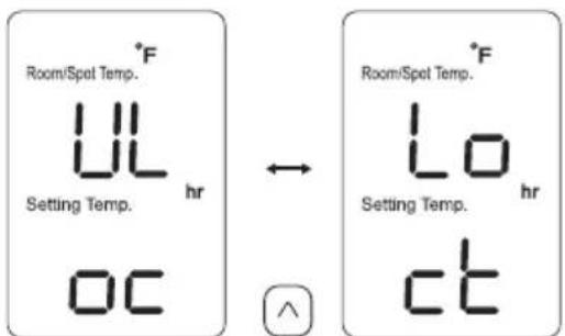
- You can set 'UNLOCK' or 'LOCK' after pressing '^' button.
● TEMPERATURE UNIT
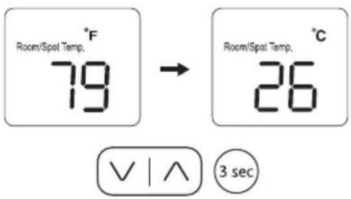
- If you want to change temperature unit ^ F ^ C, when the unit is stopped, push 'V' and '^' button simultaneously for 3 seconds.
'ERROR' and WARNING INDICATORS
| Error Code | Problem | Cause | Corrective Action |
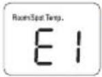 | High pressure | The water supply is cut.Ambient temperature is too high. | Confirm the water supply valve is opened.Do not use the air conditioner if ambient temperature is higher than 113°F. |
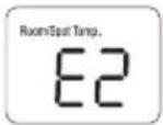 | Low pressure Verify Electrical. | Refrigerant may be low or empty. | Verify Power (Voltage / Amps).Check refrigerant level and refrigerant leakage.Clean Filter and Coil.Check Evaporator Filter.Check Evaporator Coil. |
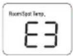 | Sensor Temperature sensor is short-circuited or cut. | Exchange temperature sensor. | |
 | Water full Condensate pump is full. Check the condensate pump or water hose is bent. | ||
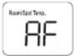 | Anti-Freezing alarm | Evaporator is below 28.4°F (-2°C) due to being used in a low ambient temperature area. | Do not use the unit in an ambient temperature less than 65°F (18°C).Check refrigerant level. |
ECONOMY MODE
| Model | Evap. Fan | Cond. Fan | Economy mode(Push the button for 3 sec.) | Etc. | ||
| Economy | Normal | Economy | Normal | |||
| HSC-12R | Stop after 30 sec. | Run | - | - |  | Fan integral type |
| HSC-14R/18R/24R | Stop after 30 sec. | Run | - | - | [KSH8] | Fan integral type |
| AHSC-14R/18R | Stop after 30 sec. | Run | - | - |  | Fan integral type |
| HSC-36R | Stop after 1 min. | Run | Stop after 1 min. | Run |  | |
| HSC-60R | Stop after 1 min. | Run | Stop after 1 min. | Run |  | |
| AHSC-42R/60R | Stop after 30 sec. | Run | Stop | Run |  | |
| AHSC-140R | Stop after 1 min. | Run | Stop after 1 min. | Run |  | |
| HWC-19R | Stop after 30 sec. | Run | - | - |  (High) (High) | |
| HWC-60R | Stop after 1 min. | Run | - | - |  | |
TROUBLE SHOOTING
| Symptom | Check Points | Measures to be Taken |
| - Is the power plug pulled out? - Insert the plug.The operationis not done.- Is the fuse cut? - Change the fuse of electric panel.- Is the circuit breaker fallen? - After confirming the load capacity, raise the circuit breaker of the distribution panel.- Is the surrounding temperature too high? - Use it at the place of 113°F and lower.(Higher than 113°F)- Is the voltage too low? - Request an electricity construction- company for the available rated voltage | ||
| - Is the filter clogged with dust? - Clean the filter (Washing with water is OK.)- Although the filter is clean, is the heat- - Clean the heat-exchanger.exchanger clogged with much dust?The cooling is not well done.- Is there any obstacle in the in-taking part?- Is the water supply cut?- Right after the operation stops, is the unit started to operate instantly? | - Is the water supply cut?- Right after the operation stops, is the unit started to operate instantly? | - Remove the obstacle. (Farther than 8inch.)- Lower than the ambient temperature.- Confirm the water supply valve is opened.- Confirm that after 3 minutes, the compressor is normally operated and the cold air is being discharged. |
| When white vapor is generated during operation. | - Is the unit being used where humidity is high? | - If the humidity is high, much air is discharged, and white vapor may be emitted. |
| When dew is formed at the discharging hole. | - Is the room temperature too high? | - It is a phenomenon that the moisture in the air is changed into dew, and this is not abnormal. |
CLEANING AND MAINTENANCE
● CLEANING THE AIR FILTERS

natural_image
Illustration of a hand blowing out a textured, irregular object into a rectangular frame (no text or symbols)- Cleaning of filter : Detach the filter from the A/C, and clean it with compressed air or water.
natural_image
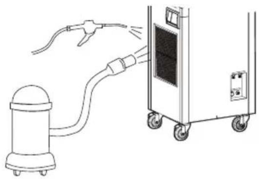
Diagram showing a fuel nozzle connecting a cylindrical device to a cart with wheels, no text or symbols present- Cleaning of heat-exchanger : Clean dust attached to the heat-exchanger with compressed air or a vacuum cleaner.
● MAINTENANCE
natural_image
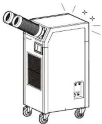
Line drawing of a portable air conditioner unit with wheels and a cylindrical tube, emitting sparkles (no text or symbols)- After cleaning, dry well the inside by blowing operation for 3\~4 hours.
natural_image
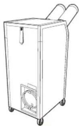
Line drawing of a portable industrial machine with two handles and a circular vent (no text or symbols)- After stopping operation and pulling out the power cord, do wind well and fix the cord.
natural_image
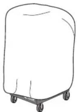
Simple line drawing of a four-wheeled cart or container (no text or symbols)- Note that moisture and dust not to enter into the unit.
※ When it is not used, close the valve of the water supplying line, and discharge the water in the line, and keep it after being dried.
- SELECTION OF THE INSTALLATION PLACE
- As the air conditioner should be connected to the tap water tube, its installation near the hydrant is good. Install it on the even and stable place.
● HOW TO CONNECT PIPES
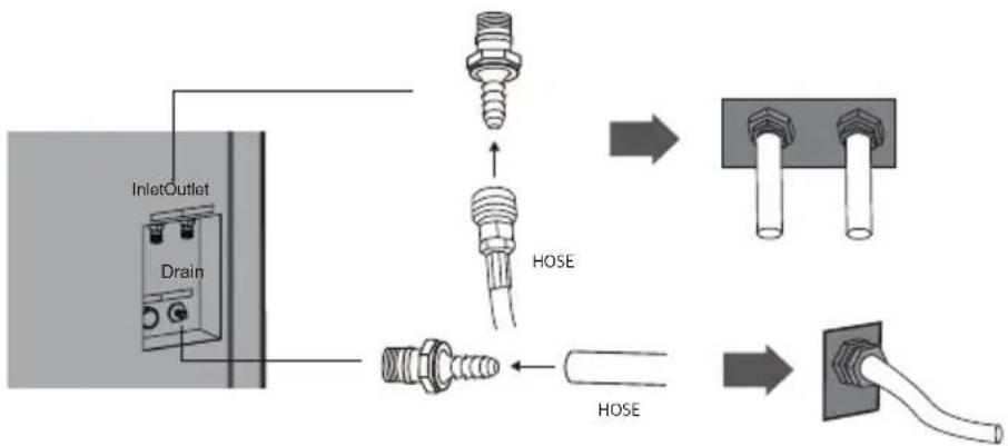
- Connect the nipple at the water in-taking hole and the water discharge hole of the backside of the air conditioner. At this time, wind the Teflon tape at the thread part and fasten it the main body.
-
Unfasten the nut and ring at the nipple and connect it to the hose, and insert the hose into the nipple and fasten it by using the nut. (When connecting the hose, make the cut surface of the hose even.)
-
Connect the water in-taking hole to the tap water tube (or a pressuring pump), and the water discharge hole to the drain hole. (Pay attention for not changing the water in-taking hole with the discharging hole.)
-
Connect the discharging hose with the condensed water discharge hole and to the draining hole.
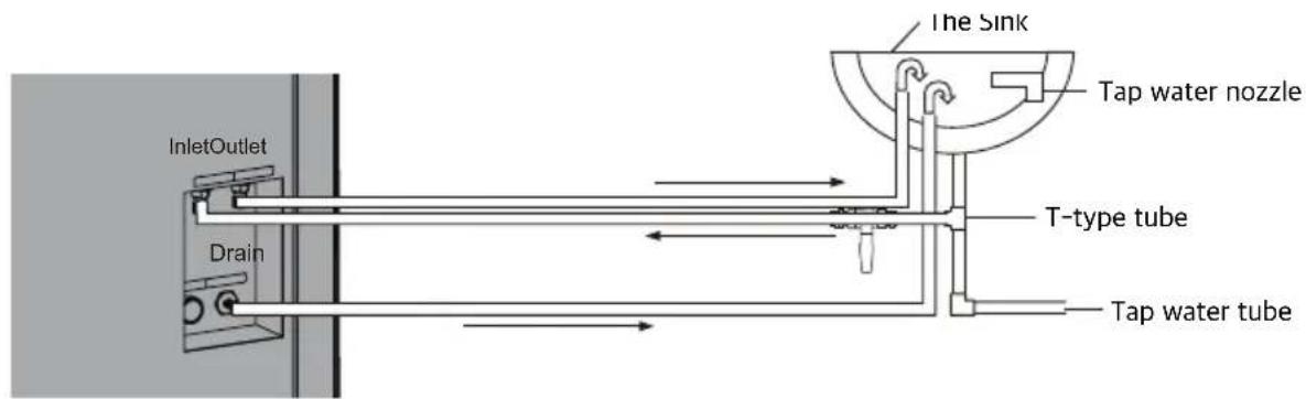
- Once the pipe connection is finished, open the valve of water supply line so that water is supplied. At this time, as water is discharged only when the air-conditioner is operated, check whether water is discharged from the drain hole.
- CHECK POINTS AFTER INSTALLATION
• After confirming the state of pipe connection, check whether a leakage is at the connection part.
- Confirm whether the connection of the drain hose is good.
- Confirm whether the earth line is good.
● PRECAUTIONS FOR INSTALLATION
- Do the earth line work in good state without fail.
(Do not connect it to the gas pipe, water pipe or telephone line.) - Connect the power source of the air-conditioner to the exclusive cable and the correct voltage.
- Do not connect the power line in the middle or extend it. (Electric shock or fire may be caused.)
- Do not install the unit at the place of an inflammable gas leakage or heat of fire.
(If the leaked gas is accumulated around the air-conditioner, a blast or fire may be caused.) - Note that if the drain hose is unstably set, water cannot be drained.
- The standard pressure of water in-taking of this product is 28\~71psig. When the pressure exceeds the standard, install a decompression device, and in case of lower pressure than the standard, install a separate device (Pressure pump, etc.).
- When installation, the standard part supplied with the air-conditioner should be installed.
- For piping for water in-taking or discharging, a hose may be used for a short distance (3\~33 ft), and for a long distance more than 33 ft, a proper material (Matchable, X-L pipe) should be installed in principle.
- Connect the pipe correctly not the in-take direction to be changed with the discharging one.
- The exposed in-taking pipe should be thermally insulated. (Condensation prevention of in-taking water and the prevention of freeze break in winter season.)
| ITEM | DRAWING | ||||
| AIR OUTLET | DUCT | Diam. 5 inch | 1 ft | ○ | 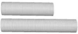 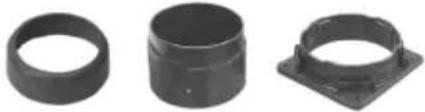 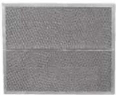 |
| 10 ft | OPTION | ||||
| DUCT COVER | ○ | ||||
| DUCT LOWER | ○ | ||||
| DUCT BASE | ○ | ||||
| ALUMINIUM FILTER CASSETTE | ○ | ||||
| HOSE KIT | QUICK COUPLER HOSE | 25 ft | OPTION |   | |
| 40 ft | |||||
| EXTENSION |  | ||||
● MANUAL PUMPING
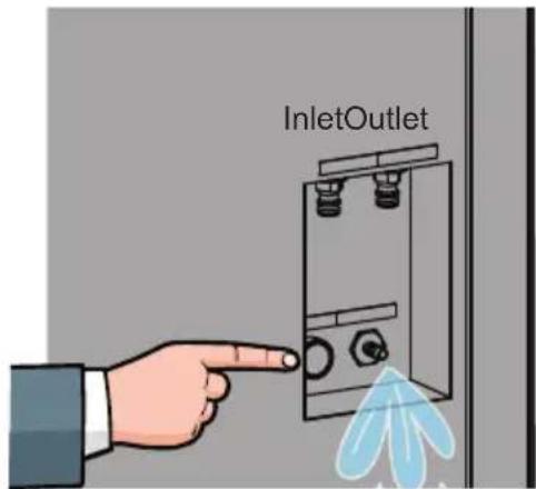
- When you keep the unit, it is necessary to empty condensate water in pump.
So press pump button to empty water in pump.
The installation, service and operation manual
natural_image
Warning symbol of a flame inside a red diamond border (no text or numbers)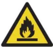
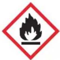
Refrigerant Safety Group A2L
WARNING
- Do not use means to accelerate the defrosting process or to clean, other than those recommended by the manufacturer.
- The appliance shall be stored in a room without continuously operating ignition sources (for example: open flames, an operating gas appliance or an operating electric heater.
- Do not pierce or burn.
- Be aware that refrigerants may not contain an odour.
- Continuous air circulation required for proper functioning. Unit must be powered except for service.
1. Installation
The appliance shall be installed in accordance with national wiring regulations.
| MODEL | HWC-19R |
| The minimum room area | 3.07 m^2 |
| The ventilation airflow volume(Q/min) 50.7 m | ^3/h |
Unventilated areas
- The non-FIXED APPLIANCE shall be stored in a room without continuously operating open flames (for example an operating gas appliance) or other POTENTIAL IGNITION SOURCES
(for example an operating electric heater, hot surfaces)
- Non-duct connected appliances containing A2L refrigerants with the supply and return air openings in the conditioned space may have the body of the appliance may be installed in open areas such as false ceilings not being used as return air plenums, as long as the conditioned air does not directly communicate with the air of the false ceiling.
The installation, service and operation manual
2. Service
2.1. Competence of service personnel
• Information of procedures additional to usual information for refrigerating appliance installation, repair, maintenance and decommission procedures is required when an appliance with FLAMMABLE REFRIGERANTS is affected.
- The training of these procedures is carried out by national training organisations or manufacturers that are accredited to teach the relevant national competency standards that may be set in legislation.
- The achieved competence should be documented by a certificate.
2.2 Information and training
The training should include the substance of the following:
- Information about the explosion potential of FLAMMABLE REFRIGERANTS to show that flammables may be dangerous when handled without care.
• Information about POTENTIAL IGNITION SOURCES, especially those that are not obvious, such as lighters, light switches, vacuum cleaners, electric heaters.
• Information about the different safety concepts.
• Information about refrigerant detectors:
- Principle of function, including influences on the operation.
- Procedures, how to repair, check or replace a refrigerant detector or parts of it in a safe way.
- Procedures, how to disable a refrigerant detector in case of repair work on the refrigerant carrying parts.
• Information about the concept of sealed components and sealed enclosures.
• Information about the correct working procedures
a) Commissioning
- Ensure that the floor area is sufficient for the REFRIGERANT CHARGE or that the ventilation duct is assembled in a correct manner.
- Connect the pipes and carry out a leak test before charging with refrigerant.
- Check safety equipment before putting into service.
b) Maintenance
- Portable equipment shall be repaired outside or in a workshop specially equipped for servicing units with FLAMMABLE REFRIGERANTS.
- Ensure sufficient ventilation at the repair place.
- Be aware that malfunction of the equipment may be caused by refrigerant loss and a refrigerant leak is possible.
- Discharge capacitors in a way that won't cause any spark. The standard procedure to short circuit the capacitor terminals usually creates sparks.
- Reassemble sealed enclosures accurately. If seals are worn, replace them.
- Check safety equipment before putting into service.
The installation, service and operation manual
c) Repair
- Portable equipment shall be repaired outside or in a workshop specially equipped for servicing units with FLAMMABLE REFRIGERANTS.
- Ensure sufficient ventilation at the repair place.
- Be aware that malfunction of the equipment may be caused by refrigerant loss and a refrigerant leak is possible.
- Discharge capacitors in a way that won't cause any spark.
- When brazing is required, the following procedures shall be carried out in the following order:
- Safely remove the refrigerant following local and national regulations. If the recovery is not required by national regulations, drain the refrigerant to the outside. Take care that the drained refrigerant will not cause any danger. In doubt, one person should guard the outlet. Take special care that drained refrigerant will not float back into the building;
- Purge the refrigerant circuit with oxygen free nitrogen;
- Evacuate the refrigerant circuit;
- Remove parts to be replaced by cutting or brazing.
- Purge the braze point with nitrogen during the brazing procedure required for repair.
- Carry out a leak test before charging with refrigerant.
d) Decommissioning
- If the safety is affected when the equipment is put out of service, the REFRIGERANT CHARGE shall be removed before decommissioning.
- Ensure sufficient ventilation at the equipment location.
- Be aware that malfunction of the equipment may be caused by refrigerant loss and a refrigerant leak is possible.
- Discharge capacitors in a way that won't cause any spark.
- Remove the refrigerant. If the recovery is not required by national regulations, drain the refrigerant to the outside. Take care that the drained refrigerant will not cause any danger.
In doubt, one person should guard the outlet. Take special care that drained refrigerant will not float back into the building.
e) Disposal
- Ensure sufficient ventilation at the working place.
- Remove the refrigerant. If the recovery is not required by national regulations, drain the refrigerant to the outside. Take care that the drained refrigerant will not cause any danger. In doubt, one person should guard the outlet. Take special care that drained refrigerant will not float back into the building.
The installation, service and operation manual
- When flammable refrigerants are used,
- evacuate the refrigerant circuit.
- purge the refrigerant circuit with oxygen free nitrogen.
- cut out the compressor and drain the oil.
Ventilated enclosure
Safety of the appliance depends on ventilation of the housing.
Switching off the appliance or opening of the enclosure has a significant effect on the safety.
Care should be taken to ensure sufficient ventilation before.
Checks to the area
Prior to beginning work on systems containing FLAMMABLE REFRIGERANTS, safety checks are necessary to ensure that the risk of ignition is minimized.
For repair to the REFRIGERATING SYSTEM, 1 to 5 shall be completed prior to conducting work on the system.
- Work procedure
Work shall be undertaken under a controlled procedure so as to minimize the risk of a flammable gas or vapour being present while the work is being performed.
- General work area
All maintenance staff and others working in the local area shall be instructed on the nature of work being carried out. Work in confined spaces shall be avoided.
- Checking for presence of refrigerant
The area shall be checked with an appropriate refrigerant detector prior to and during work, to ensure the technician is aware of potentially toxic or flammable atmospheres. Ensure that the leak detection equipment being used is suitable for use with all applicable refrigerants, i.e. non-sparking, adequately sealed or intrinsically safe.
- Presence of fire extinguisher
If any hot work is to be conducted on the refrigerating equipment or any associated parts, appropriate fire extinguishing equipment shall be available to hand. Have a dry powder or CO^2 fire extinguisher adjacent to the charging area.
The installation, service and operation manual
5. No ignition sources
No person carrying out work in relation to a REFRIGERATING SYSTEM which involves exposing any pipe work shall use any sources of ignition in such a manner that it may lead to the risk of fire or explosion.
All possible ignition sources, including cigarette smoking, should be kept sufficiently far away from the site of installation, repairing, removing and disposal, during which refrigerant can possibly be released to the surrounding space. Prior to work taking place, the area around the equipment is to be surveyed to make sure that there are no flammable hazards or ignition risks. “No Smoking” signs shall be displayed.
Checks to the refrigerating equipment
Where electrical components are being changed, they shall be fit for the purpose and to the correct specification. At all times the manufacturer's maintenance and service guidelines shall be followed. If in doubt, consult the manufacturer's technical department for assistance.
The following checks shall be applied to installations using FLAMMABLE REFRIGERANTS:
- the actual REFRIGERANT CHARGE is in accordance with the room size within which the refrigerant containing parts are installed;
- the ventilation machinery and outlets are operating adequately and are not obstructed;
- if an indirect refrigerating circuit is being used, the secondary circuit shall be checked for the presence of refrigerant;
- marking to the equipment continues to be visible and legible. Markings and signs that are illegible shall be corrected;
- refrigerating pipe or components are installed in a position where they are unlikely to be exposed to any substance which may corrode refrigerant containing components, unless the components are constructed of materials which are inherently resistant to being corroded or are suitably protected against being so corroded.
Checks to electrical devices
Repair and maintenance to electrical components shall include initial safety checks and component inspection procedures. If a fault exists that could compromise safety, then no electrical supply shall be connected to the circuit until it is satisfactorily dealt with. If the fault cannot be corrected immediately but it is necessary to continue operation, an adequate temporary solution shall be used. This shall be reported to the owner of the equipment so all parties are advised.
Initial safety checks shall include:
- that capacitors are discharged: this shall be done in a safe manner to avoid possibility of sparking;
- that no live electrical components and wiring are exposed while charging, recovering or purging the system;
• that there is continuity of earth bonding.
The installation, service and operation manual
Repairs to sealed components
- During repairs to sealed components, all electrical supplies shall be disconnected from the equipment being worked upon prior to any removal of sealed covers, etc. If it is absolutely necessary to have an electrical supply to equipment during servicing, then a permanently operating form of leak detection shall be located at the most critical point to warn of a potentially hazardous situation.
- Particular attention shall be paid to the following to ensure that by working on electrical components, the casing is not altered in such a way that the level of protection is affected. This shall include damage to cables, excessive number of connections, terminals not made to original specification, damage to seals, incorrect fitting of glands, etc.
Repair to intrinsically safe components
Do not apply any permanent inductive or capacitance loads to the circuit without ensuring that this will not exceed the permissible voltage and current permitted for the equipment in use.
Intrinsically safe components are the only types that can be worked on while live in the presence of a flammable atmosphere. The test apparatus shall be at the correct rating.
Replace components only with parts specified by the manufacturer. Other parts may result in the ignition of refrigerant in the atmosphere from a leak.
NOTE The use of silicon sealant can inhibit the effectiveness of some types of leak detection equipment. Intrinsically safe components do not have to be isolated prior to working on them.
Cabling
Check that cabling will not be subject to wear, corrosion, excessive pressure, vibration, sharp edges or any other adverse environmental effects.
The check shall also take into account the effects of aging or continual vibration from sources such as compressors or fans.
Detection of flammable refrigerants
Under no circumstances shall potential sources of ignition be used in the searching for or detection of refrigerant leaks. A halide torch (or any other detector using a naked flame) shall not be used.
The following leak detection methods are deemed acceptable for all refrigerant systems.
Electronic leak detectors may be used to detect refrigerant leaks but, in the case of FLAMMABLE REFRIGERANTS, the sensitivity may not be adequate, or may need re-calibration.
(Detection equipment shall be calibrated in a refrigerant-free area.) Ensure that the detector is not a potential source of ignition and is suitable for the refrigerant used. Leak detection equipment shall be set at a percentage of the LFL of the refrigerant and shall be calibrated to the refrigerant employed, and the appropriate percentage of gas (25 % maximum) is confirmed.
The installation, service and operation manual
NOTE Examples of leak detection fluids are
- bubble method,
- fluorescent method agents.
If a leak is suspected, all naked flames shall be removed/extinguished.
If a leakage of refrigerant is found which requires brazing, all of the refrigerant shall be recovered from the system, or isolated (by means of shut off valves) in a part of the system remote from the leak.
Removal of refrigerant shall be according to the following procedures shall be carried out in the following order:
- Safely remove the refrigerant following local and national regulations. If the recovery is not required by national regulations, drain the refrigerant to the outside. Take care that the drained refrigerant will not cause any danger. In doubt, one person should guard the outlet. Take special care that drained refrigerant will not float back into the building.
- Purge the refrigerant circuit with oxygen free nitrogen.
- Evacuate the refrigerant circuit.
- Remove parts to be replaced by cutting or brazing.
- Purge the braze point with nitrogen during the brazing procedure required for repair.
- Carry out a leak test before charging with refrigerant.
Charging procedures
In addition to conventional charging procedures, the following requirements shall be followed.
- Ensure that contamination of different refrigerants does not occur when using charging equipment. Hoses or lines shall be as short as possible to minimise the amount of refrigerant contained in them.
- Cylinders shall be kept in an appropriate position according to the instructions.
- Ensure that the REFRIGERATING SYSTEM is earthed prior to charging the system with refrigerant.
- Label the system when charging is complete (if not already).
- Extreme care shall be taken not to overfill the REFRIGERATING SYSTEM.
Decommissioning
Before carrying out this procedure, it is essential that the technician is completely familiar with the equipment and all its detail. It is recommended good practice that all refrigerants are recovered safely.
Prior to the task being carried out, an oil and refrigerant sample shall be taken in case analysis is required prior to re-use of recovered refrigerant. It is essential that electrical power is available before the task is commenced.
a) Become familiar with the equipment and its operation.
b) Isolate system electrically.
The installation, service and operation manual
c) Before attempting the procedure, ensure that:
- mechanical handling equipment is available, if required, for handling refrigerant cylinders;
- all personal protective equipment is available and being used correctly;
- the recovery process is supervised at all times by a competent person;
- recovery equipment and cylinders conform to the appropriate standards.
d) Pump down refrigerant system, if possible.
e) If a vacuum is not possible, make a manifold so that refrigerant can be removed from various parts of the system.
f) Make sure that cylinder is situated on the scales before recovery takes place.
g) Start the recovery machine and operate in accordance with instructions.
h) Do not overfill cylinders (no more than 80 % volume liquid charge).
i) Do not exceed the maximum working pressure of the cylinder, even temporarily.
j) When the cylinders have been filled correctly and the process completed, make sure that the cylinders and the equipment are removed from site promptly and all isolation valves on the equipment are closed off.
k) Recovered refrigerant shall not be charged into another REFRIGERATING SYSTEM unless it has been cleaned and checked.
Labelling
Equipment shall be labelled stating that it has been de-commissioned and emptied of refrigerant. The label shall be dated and signed.
For appliances containing FLAMMABLE REFRIGERANTS, ensure that there are labels on the equipment stating the equipment contains FLAMMABLE REFRIGERANT.
Recovery
When removing refrigerant from a system, either for servicing or decommissioning, it is recommended good practice that all refrigerants are removed safely.
When transferring refrigerant into cylinders, ensure that only appropriate refrigerant recovery cylinders are employed. Ensure that the correct number of cylinders for holding the total system charge is available. All cylinders to be used are designated for the recovered refrigerant and labelled for that refrigerant (i.e. special cylinders for the recovery of refrigerant). Cylinders shall be complete with pressure-relief valve and associated shut-off valves in good working order. Empty recovery cylinders are evacuated and, if possible, cooled before recovery occurs.
The installation, service and operation manual
The recovery equipment shall be in good working order with a set of instructions concerning the equipment that is at hand and shall be suitable for the recovery of the flammable refrigerant.
If in doubt, the manufacturer should be consulted. In addition, a set of calibrated weighing scales shall be available and in good working order. Hoses shall be complete with leak-free disconnect couplings and in good condition.
The recovered refrigerant shall be processed according to local legislation in the correct recovery cylinder, and the relevant waste transfer note arranged. Do not mix refrigerants in recovery units and especially not in cylinders.
If compressors or compressor oils are to be removed, ensure that they have been evacuated to an acceptable level to make certain that flammable refrigerant does not remain within the lubricant.
The compressor body shall not be heated by an open flame or other ignition sources to accelerate this process. When oil is drained from a system, it shall be carried out safely.
3. Transportation, marking and storage
3.1. Transportation
Attention is drawn to the fact that additional transportation regulations may exist with respect to equipment containing flammable gas.
The maximum number of pieces of equipment or the configuration of the equipment permitted to be transported together will be determined by the applicable transport regulations.
3.2. Marking
Signs for similar appliances used in a work area are generally addressed by local regulations and give the minimum requirements for the provision of safety and/or health signs for a work location.
All required signs are to be maintained and employers should ensure that employees receive suitable and sufficient instruction and training on the meaning of appropriate safety signs and the actions that need to be taken in connection with these signs.
The effectiveness of signs should not be diminished by too many signs being placed together.
Any pictograms used should be as simple as possible and contain only essential details.
Disposal of equipment using flammable refrigerants
See national regulations.
The installation, service and operation manual
3.3. Storage
The storage of the appliance should be in accordance with the applicable regulations or instructions, whichever is more stringent.
Storage of packed (unsold) equipment
Storage package protection should be constructed in such a way that mechanical damage to the equipment inside the package will not cause a leak of the REFRIGERANT CHARGE.
The maximum number of pieces of equipment permitted to be stored together will be determined by local regulations.
natural_image
Warning symbol of a flame inside a red diamond border (no text or numbers)
Refrigerant Safety Group A2L
ATTENTION
- agents fluorescents.
(Applicable to first retail purchaser only)
AIRREX unit gives the more reliable performance, comfort and durability the more they are used. They are built under a strict quality assurance regime which includes inspection both during and after production and exhaustive reliability testing.
In the unlikely event you have any problems, please contact your dealer or distributor. If the problem is as a result of a production fault or failure, repairs will be undertaken free of charge during the period of warranty subject to the following warranty conditions:
- If the problem has been caused by customer error or misuse, abuse or damage, then all repairs will be charged for.
- This warranty applies to your country.
- Proof and date of purchase must be supplied.
- Please complete the details below and keep this warranty in a safe place.
- All transportation charges back to the dealer are at customer's cost. Keep all original packaging to facilitate return. Return to customer will be at dealer's cost (if genuine warranty claim).
| DESCRIPTION AIRREX | Water-cooled AIR CONDITIONER | ||
| MODEL HWC-19R | |||
| DATE OF PURCHASE PRODUCT SERIAL NO. | |||
| WARRANTY PERIOD ( ) Months | |||
| DISTRIBUTOR | Name of Company | ||
| Telephone No. | |||
| CUSTOMER DETAILS | Name : | ||
| Address : | |||
| Telephone : | |||
| CUSTOMER DETAILS | Name : |
| Address : | |
| Telephone : |
TEMP-AIR
EQUIPMENT SALES
www.tempairsales.com

2031 Exchange Parkway, Suite A, Waco, TX 76712

888-535-8841

sales@tempairsales.com

US Electrical Standards (ETL)
- TABLE OF CONTENTS
- WARNING
- CAUTION
- EXTERIOR DESCRIPTION
- ● BACK & SIDE VIEW
- CONTROL PANEL FUNCTIONS
- MODE CHANGING METHOD
- COOLING MODE
- FAN MODE
- ● DEHUMIDIFICATION MODE
- STEP 1
- STEP 2
- STEP 3
- CANCEL
- ● Display Room Temperature Range & Setting Range.
- - SPOT or ROOM MODE
- - LOCK or UNLOCK
- ● TEMPERATURE UNIT
- 'ERROR' and WARNING INDICATORS
- ECONOMY MODE
- TROUBLE SHOOTING
- CLEANING AND MAINTENANCE
- ● CLEANING THE AIR FILTERS
- ● MAINTENANCE
- - SELECTION OF THE INSTALLATION PLACE
- ● HOW TO CONNECT PIPES
- - CHECK POINTS AFTER INSTALLATION
- ● PRECAUTIONS FOR INSTALLATION
- ● MANUAL PUMPING
- The installation, service and operation manual
- Installation
- Unventilated areas
- Service
- Competence of service personnel
- Information and training
- c) Repair
- d) Decommissioning
- e) Disposal
- No ignition sources
- Checks to the refrigerating equipment
- Checks to electrical devices
- Repairs to sealed components
- Repair to intrinsically safe components
- Cabling
- Detection of flammable refrigerants
- Charging procedures
- Decommissioning
- Labelling
- Recovery
- Transportation, marking and storage
- Transportation
- Marking
- Storage
- ATTENTION
Brand : Airrex
Model : HWC-19R
Category : Air Conditioning