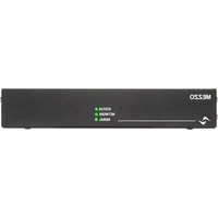
Mezzo 322 - Receiver Powersoft - Free user manual and instructions
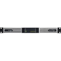
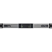
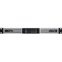
Find the device manual for free Mezzo 322 Powersoft in PDF.


| Product type | Professional audio amplifier |
| Brand | Powersoft |
| Model | Mezzo 322 |
| Number of channels | 2 channels |
| Power supply | 100-240 V AC, 50/60 Hz |
| Maximum power consumption | 375 VA |
| Maximum output voltage | 100 V RMS (selectable 25 V, 70 V, 100 V) |
| Automatic standby mode | Yes, after 25 minutes without signal |
| Integrated DSP | Yes, automatic and advanced configuration via ArmoníaPlus |
| Network connectivity | Ethernet (Dante/AES67 on A+ and AD models) |
| Audio inputs | 2 balanced and 2 unbalanced |
| Speaker outputs | 2 channels, locking connectors |
| Mounting options | 19-inch rack, half-rack, wall, under-table |
| Cooling | Variable speed fan (3 modes) |
| Operating temperature | 0 °C to +50 °C (derating >35 °C) |
| Operating humidity | 10% to 85% non-condensing |
| Maximum altitude | 2000 m |
| Usage | Indoor only |
| Cleaning | Unplug before cleaning, dry cloth |
| Repairability | No user-serviceable parts |
| Warranty | Limited, repairs by authorized center |
| Compliance | CE, WEEE, RoHS |
Frequently Asked Questions - Mezzo 322 Powersoft
User questions about Mezzo 322 Powersoft
0 question about this device. Answer the ones you know or ask your own.
Ask a new question about this device
Download the instructions for your Receiver in PDF format for free! Find your manual Mezzo 322 - Powersoft and take your electronic device back in hand. On this page are published all the documents necessary for the use of your device. Mezzo 322 by Powersoft.
USER MANUAL Mezzo 322 Powersoft
Important Safety Instructions
Common symbols and meanings

THE TRIANGLE WITH THE LIGHTNING BOLT IS USED TO ALERT THE USER TO THE RISK OF ELECTRIC SHOCK.
THE TRIANGLE WITH THE EXCLAMATION POINT IS USED TO ALERT THE USER TO IMPORTANT OPERATING OR MAINTENANCE INSTRUCTIONS.
THE CE-MARK INDICATES THE COMPLIANCE OF THE PRODUCT TO ALL THE APPLICABLE EUROPEAN DIRECTIVES
SYMBOL FOR EARTH/GROUND CONNECTION.
SYMBOL INDICATING THAT THE EQUIPMENT IS FOR INDOOR USE ONLY.
SYMBOL FOR CONFORMITY WITH DIRECTIVE 2012/19/EC OF THE EUROPEAN PARLIAMENT ON WASTE ELECTRICAL AND ELECTRONIC EQUIPMENT (WEEE).
Safety Warnings
OPERATING TEMPERATURE RANGE: 0°C TO +50°C - DERATING ABOVE 35°C.
STORAGE RELATIVE HUMIDITY RANGE: 10% TO 85% HUMIDITY (NON CONDENSING).
DO NOT USE THE UNIT AT ALTITUDES ABOVE 2000 M.
DO NOT USE THE UNIT IN TROPICAL ENVIRONMENT.
TO REDUCE THE RISK OF ELECTRIC SHOCK, DO NOT ATTEMPT TO OPEN ANY PART OF THE UNIT. NO USER-SERVICEABLE PARTS INSIDE. REFER SERVICING TO QUALIFIED SERVICE PERSONNEL.
CONNECTION TO THE MAINS SHALL BE DONE ONLY BY A ELECTROTECHNICAL SKILLED PERSON ACCORDING THE NATIONAL REQUIREMENTS OF THE COUNTRIES WHERE THE UNIT IS SOLD.
DO NOT USE THIS AMPLIFIER IF THE ELECTRICAL POWER CORD IS FRAYED OR BROKEN.
TO AVOID ELECTRICAL SHOCK, DO NOT TOUCH ANY EXPOSED SPEAKER WIRING WHILE THE AMPLIFIER IS OPERATING.
DO NOT SPILL WATER OR OTHER LIQUIDS INTO OR ON THE AMPLIFIER.
THIS DEVICE MUST BE POWERED EXCLUSIVELY BY EARTH CONNECTED MAINS SOCKETS IN ELECTRICAL NETWORKS COMPLIANT TO THE IEC 364 OR SIMILAR RULES
DISCONNECT THE AC MAINS SOURCE BEFORE ATTEMPTING TO CLEAN ANY PART OF THE AMPLIFIER
THE BREAKER NEEDS TO SUPPORT 375 VA PER MEZZO, SO MAX 3 MEZZO PER OUTLET AT 115V 10A, OR MAX 6 MEZZO PER OUTLET WITH 230V 10A
OUTPUT TERMINALS ARE HAZARDOUS: WIRING CONNECTION TO THESE TERMINALS REQUIRES INSTALLATION BY AN INSTRUCTED PERSON AND THE USE OF READY MADE LEADS.
PROPERLY FIT THE AC MAINS PLUG TO THE AMPLIFIER INLET. BEFORE POWERING THIS AMPLIFIER, VERIFY THAT THE CORRECT VOLTAGE RATING IS BEING USED.
TAKE CARE TO LOCK THE OUTPUT TERMINAL BEFORE SWITCHING THE DEVICE ON.
VERIFY THAT YOUR MAINS CONNECTION IS CAPABLE OF SATISFYING THE POWER RATINGS OF THE DEVICE.
NO NAKED FLAME SOURCES SUCH AS LIGHTED CANDLES SHOULD BE PLACED ON THE AMPLIFIER.
IT IS HIGHLY RECOMMENDED TO UNPLUG THE OUTPUT CONNECTORS BEFORE PROCEEDING WITH THE SELF CHECK PROCEDURE
THE TESTING SIGNALS MIGHT CAUSE LOUDSPEAKER IMPAIRMENTS.
WARNING TO PREVENT INJURY, THIS APPARATUS MUST BE SECURELY ATTACHED TO THE FLOOR/WALL/RACK IN ACCORDANCE WITH THE INSTALLATION INSTRUCTIONS.
THE MANUFACTURER CANNOT BE HELD RESPONSIBLE FOR DAMAGES CAUSED TO PERSONS, THINGS OR DATA DUE TO AN IMPROPER OR MISSING GROUND CONNECTION.
IT IS ABSOLUTELY NECESSARY TO VERIFY THESE FUNDAMENTAL REQUIREMENTS OF SAFETY AND, IN CASE OF DOUBT, REQUIRE AN ACCURATE CHECK BY QUALIFIED PERSONNEL.

Please read and keep all safety and use instructions.
This product is intended for installation by professional installers only! This document is intended to provide professional installers with basic installation and safety guidelines for this product in typical fixed-installation systems. Please read this document and all safety warnings before attempting installation.
- Read these instructions.
- Keep these instructions.
- Heed all warnings.
- Follow all instructions.
- Do not use this equipment near water.
-
Clean only with a dry cloth.
-
Do not block any ventilation openings. Install in accordance with the manufacturer's instructions.
-
Do not install near any heat sources such as radiators, heat registers, stoves, or other apparatus that produce heat.
-
Do not defeat the safety purpose of the polarized or grounding-type plug. A polarized plug has two blades with one wider than the other. A grounding-type plug has two blades and a third grounding prong. The wide blade or the third prong are provided for your safety. If the provided plug does not fit into your outlet, consult an electrician for replacement of the obsolete outlet.
-
Protect the power cord from being walked on or pinched particularly at plugs, convenience receptacles, and the point where they exit from the apparatus.
-
Only use attachments/accessories specified by the manufacturer.
-
Use only with the cart, stand, tripod, bracket, or table specified by the manufacturer, or sold with the apparatus. When a cart is used, use caution when moving the cart/apparatus combination to avoid injury from tip-over.
-
Unplug this apparatus during lightning storms or when unused for long periods of time.
-
Refer all servicing to qualified service personnel. Servicing is required when the apparatus has been damaged in any way, such as power-supply cord or plug is damaged, liquid has been spilled or objects have fallen into the apparatus, the apparatus has been exposed to rain or moisture, does not operate normally, or has been dropped.
Warranty and Technical Service
This product is covered by a limited warranty.

This Powersoft product contains no user-serviceable parts. All warranty repairs must be carried by a certified technician operating in a Powersoft Authorized Service Centre.
Contact The Authorized Service Center For Ordinary And Extraordinary Maintenance. To learn more about warranty terms and conditions, visit powersoft.com/warranty
For any service related enquiry, please visit powersoft.com/en/product-repair/

EC Declaration Of Conformity
Regulatory Compliance Statements
Europe
If the time arises to dispose of your product, please recycle all possible component. This symbol indicates that when the end-user wishes to discard this product, it must be sent to separate collection facilities for recovery and recycling. By separating this product from other household-type waste, the volume of waste sent to incinerators or land-fills will be reduced and natural resources will thus be conserved.
The Waste Electrical and Electronic Equipment Directive (WEEE Directive) aims to minimise the impact of electrical and electronic goods on the environment. Powersoft S.p.A. comply with the Directive 2012/19/EU of the European Parliament on waste electrical finance the cost of treatment and recovery of electronic equipment (WEEE) in order to reduce the amount of WEEE that is being disposed of in land-fill site. All of our products are marked with the WEEE symbol; this indicates that this product must NOT be disposed of with other waste. Instead it is the user's responsibility to dispose of their waste electrical and electronic equipment by handing it over to an approved reprocessor, or by returning it to Powersoft S.p.A. for reprocessing. For more information about where you can send your waste equipment for recycling, please contact Powersoft S.p.A. or one of your local distributors.
USA
FCC Supplier's Declaration of Conformity
Responsible Party:
Powersoft S.p.A.
Via Enrico Conti, 5
50018 Scandicci (FI) – Italy
Phone: +39 055 735 0230
Fax: +39 055 735 6235
FCC Compliance Statement
This device complies with part 15 of the FCC rules. Operation is subject to the following two conditions:
1) This device may not cause harmful interference, and
2) this device must accept any interference received, including interference that may cause undesired operation.
CAUTION: Changes or modifications not expressly approved by the party responsible for compliance could void the user's authority to operate the equipment. NOTE: This equipment has been tested and found to comply with the limits for a Class B digital device, pursuant to part 15 of the FCC Rules. This equipment generates, uses, and can radiate radio frequency energy and, if not installed and used in accordance with the instruction manual, may cause harmful interference to radio communications. However, there is no guarantee that interference will not occur in a particular installation. If this equipment does cause harmful interference to radio or television reception, which can be determined by turning the equipment off and on, the user is encouraged to try to correct the interference by one or more of the following measures:
- Reorient or relocate the receiving antenna.
- Increase the separation between the equipment and receiver.
- Connect the equipment into an outlet on a circuit
- Different from that to which the receiver is connected.
Canada
Canadian Caution
This device contains licence-exempt transmitter(s)/receiver(s) that comply with Innovation, Science and Economic Development Canada's licence-exempt RSS(s). Operation is subject to the following two conditions:
1) This device may not cause interference.
2) This device must accept any interference, including interference that may cause undesired operation of the device.
Radiation Exposure Statement
This equipment complies with RSS-102 radiation exposure limits set forth for an uncontrolled environment. This equipment should be installed and operated with minimum distance 20cm between the radiator & your body.
Manufacturer:
Powersoft S.p.A.
via E. Conti 5
50018 Scandicci (Fi)
Italy

We declare that under our sole responsibility the products:
Model Names:
MEZZO 322 A
MEZZO 324 A
MEZZO 602 A
MEZZO 604 A
MEZZO 322 A+
MEZZO 324 A+
MEZZO 602 A+
MEZZO 604 A+
MEZZO 322 AD
MEZZO 324 AD
MEZZO 602 AD
MEZZO 604 AD
Intended use: Professional Audio Amplifier
Are in conformity with the provisions of the following EC Directives, including all amendments, and with national legislation implementing these directives:
2014/35/EU Low Voltage Directive
2014/30/EU Electromagnetic Compatibility Directive
2011/65/EU RoHs Directive
The following harmonized standards are applied:
EN 55032:2015,
EN 55032:2015 /A11:2020
EN 55035:2017,
EN 55035:2017 /A11:2020
EN 61000-3-2:2014
EN 61000-3-3:2013
EN 61000-3-11:2000
EN 62368-1:2014
EN 62368-1:2014 /AC:2015
Scandicci,
January 2022
Marco Cati
Quality & After Sales Manager
For compliance questions only: compliance@powersoft.it
EN
Preliminary operations
Package list
The box contains the following:
1x Mezzo amplifier
Block connectors
2x Type-A Brackets
2x Type-B Brackets
Screws (for attaching the brackets)
3x Mains power cable
1x L-shaped T8 key
1x Output plug retainer
1x Wall mount drilling template sheet
Location
Install your amplifier in a location that allows some exchange of air. The Amplifier comes with mounting accessories for the following mounting options:
On a shelf – The rubber feet allow you to set your amplifier on any flat surface.
Custom mount – It's possible to custom design fittings for poles and other applications using screws fitting the threaded holes in the amplifier. These screws must not be longer than 8 mm. The safest way to avoid mistakes is to use the provided screws.
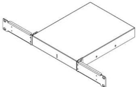
Single 19" rack mount – With the two type-A brackets, it's possible to mount a single amplifier in a 19" rack.
natural_image
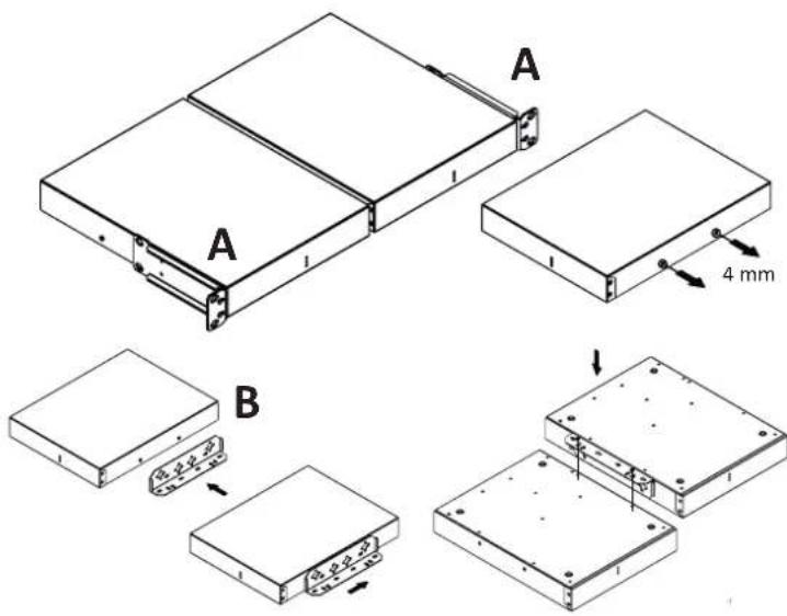
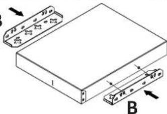
Technical line drawing of a mechanical assembly with two vertical metal brackets and a rectangular plate (no text or symbols)Tandem 19" rack mount – With one type-B bracket, it is possible to mount two Mezzo amplifiers side by side and then mount them in a 19" rack using the two type-A brackets provided.
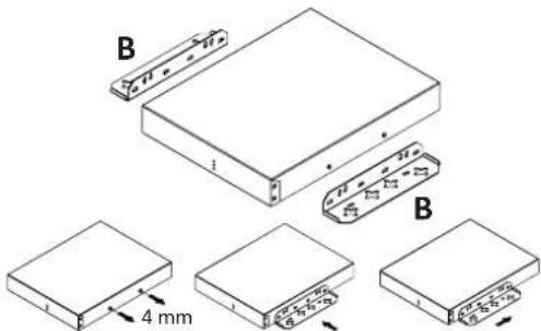
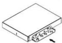
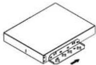
Unscrew the indicated screws on the first Mezzo without removing them completely. Set the type-B bracket in place by slotting the screws into the keyholes and fasten them back in without overtightening. Flip both amplifiers upside down. Match the holes of the B bracket with those on the second Mezzo and secure with the additional screws provided.
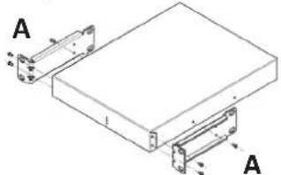
Apply the two type-A brackets by removing the screws on each side, matching the resulting screw holes with those on the bracket, and tightening back the original screws without overtightening them.
Single half rack mount – With the two type A bracket, it's possible to mount a single amplifier in a half width rack.
natural_image
Technical diagram of a mechanical assembly with two labeled components (A), showing internal components and mounting features (no text or symbols present)Surface mount – With two type-B brackets, it is possible to mount an amplifier vertically on a wall, or upside down under a table or in a ceiling. In the latter case, just flip the brackets upside down.
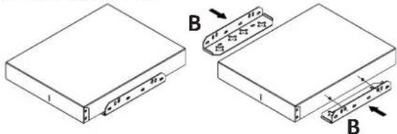
Surface mount (hidden brackets) – With two type-B brackets, it is possible to mount a Mezzo on flat surfaces while hiding the brackets underneath the amplifier.
Use the drilling template (included in the box) to mount at least two screws on the wall, attach the brackets to the amplifier, then just slide it onto the wall screws.
Cooling
When exposed to high ambient temperatures, Mezzo will start automatically reducing the output power (depending on the type of load and the duration of heat exposure) and the STATUS LED will start flashing in yellow to display this limiter is active.
If the ambient temperature is extremely high (considerably above the indicated limits), the over temperature will cause the amplifier to mute all output channels, and the STATUS LED will show a solid red colour. The outputs will automatically start operating again once the temperature cools down.
The 320W models have an internal fan that does not exchange air with the outside, but dissipates the heat inside the enclosure itself. Conversely, the 600W models implement a temperature controlled forced-air cooling system, where air enters from the front and exists at the back of the amplifier. The fan in the 600W amps has 3 modes:
STILL - if the temperature of the space surrounding the amplifier is ≤ 35^ and the average output power is ≤ 1 W per channel.
WHISPER - if the average output is ≤4 W per channel. The fan noise at 1 m is ≤30 dBA in this mode.
REGULATED - Mezzo adapts the speed of the fan to maintain lower temperatures. The fan noise at 1 m is ≤45 dBA in this mode
Set-up and Operation
Power State
This amplifier doesn't have a power switch. It's designed to turn on automatically as soon as you connect it to an AC power source.
To conserve energy, the amplifier is equipped with an auto-standby feature, enabled by default. If no signal is detected for a duration of 25 minutes, the amplifier will transition into standby mode.
The amplifier is calibrated to recognize an input signal based on a threshold of -50 dBu (equivalent to approximately 2.5 mV) for analog inputs or -71 dBFS for digital inputs. If the input signal surpasses this
threshold, the amplifier will stay active or wake up from standby Step 2 – Calibrate mode as necessary.
The auto-standby feature can be disabled via ArmoníaPlus, in this case, the amplifier will always stay active.
DSP and matrix configuration
The amplifier comprises a comprehensive range of functions that can be setup in two ways.
• Automatic - without the use of any app or software.
- Advanced - via the software ArmoniaPlus or third-party API.
Automatic configuration
This is a very easy way to configure the amplifier that doesn't require any software.
The automatic setup will set limiters so that a channel reaches the maximum capacity of the power supply, with a 4 dBu balanced analog input (or -6 dBFS for Dante/AES67). This means that it also adjusts the gain so that the amplifier has the gain needed for all channels. The way to “assign power” is then simply done by adjusting the level of the content to the different channels.
It will also set the high-pass filters automatically. The cutoff will be selected so that frequencies below the resonance frequency, as well as frequencies that saturate transformers in Hi-Z loudspeakers, will be attenuated.
Note! Automatic configuration is only possible, and repeatable, when no amplifier settings and parameters have been manually altered. In the case of manual changes, it will still be possible to trigger the auto configuration, but for verification and monitoring purposes only. The new measured values will not be saved until settings and parameters are set back to their initial values or a factory reset is done.
Factory Reset
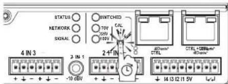
To perform a factory reset, start by unplugging the mains cable. Press and hold the push button on the amplifier's rear panel and reconnect the mains cable while still pressing the button. Keep holding the button (for about 10s) until the 'Signal' and 'Status' LEDs light up in red and release. The 'Signal' and 'Status' LEDs will flash in red three times confirming the factory reset. It is important to release the button while the 'Signal' and 'Status' LEDs are still on in red and to see the flashing LEDs that confirm the reset.
Step 1 - Select the maximum voltage
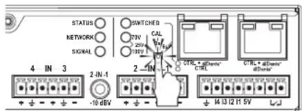
No channel will ever be assigned limiters that exceed the power of the power supply. The main reason for selecting the maximum voltage is to ensure that 25/70/100V loudspeakers will get the power selected on their tapping, if a channel is using less power than it can deliver.
If the application is 25V or 70V, then there is a risk that the limiters get set too high if the connected load isn't requiring full power. The maximum voltage can be selected with short presses on the push button on the amplifier's rear panel. The selected voltage will be displayed as follows:
| 70VLED | 100VLED | Max Peak Voltage | Max RMS Voltage | Description |
| Unlit | Lit 141.4 V | peak | 100 V_ rms | Also works in mixed configurations of 100V and Lo-Z speakers |
| Lit | Unlit 100 V | peak | 70.7 V_ rms | Also works in mixed configurations of 70V and Lo-Z speakers |
| Lit | Lit | 35.4 V_ peak | 25 V_ rms | Also works in mixed configurations of 25V and Lo-Z speakers |
| Unlit | Unlit | Custom Settings | Cannot be selected from the rear panel. Parameters have been manually set for all channels via software and automatic configuration is not available | |
Please note that for low-impedance loads, it is not necessary to select the maximum voltage.
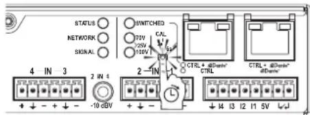
Press the push button until the 'Signal' LED turns purple and release while the LED is still on. This will trigger an automatic impedance measurement for each channel. The amplifier will differentiate between Lo-Z and Hi-Z loads and will automatically set high-pass filters, limiters and gain for each channel. Please note that it may generate an SPL exceeding 95 dB if the loudspeakers are sensitive enough.
Following the measurement procedure, the 'Signal' and 'Status' LEDs will flash in green, indicating that the calibration was successful. Other colours indicate different measurement results, such as detection of open loads or output short-circuits in the outputs. A dedicated LED chart with the list of possible results is available further down in this manual.
Network Reset and Operation Mode
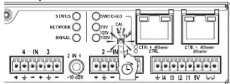
Press the push button until the 'Network' LED turns cyan and release while the LED is still on. This will reset the amplifier's network configurations and put it in DHCP mode. In A+ and AD models, this operation will also change the operation mode of the ethernet ports as indicated by the 'Switched' LED:
- Lit: The default “switched mode” configuration. The two ports are connected and will both work for Dante/AES67 and control/ monitoring of the amplifier's DSP. It means that only one Ethernet cable is necessary for control and Dante audio. It also means that the product can be inserted in a daisy chain of other Gigabit Ethernet products as long as there is enough bandwidth.
- Unlit: The internal ethernet switch is disabled. The two ports are not connected and the port on the right-hand side is assigned to Dante/AES67 only. The port on the left is only for controlling/monitoring the amplifier's DSP.
Routing and control via GPI
I/O Routing - 4-Channel models
All 4-channel models allow straight 4-in/4-out analogue routing, where analogue inputs labelled 1 and 2 are a summation of balanced and unbalanced inputs. When using unbalanced inputs only, these will get a 12dB boost so that normal unbalanced sources will deliver enough level to drive the amplifier to full power. When using both balanced and unbalanced inputs simultaneously, the latter will get a further -30dB reduction, so that priority is given to balanced sources.
I/O Routing - 2-Channel models
All 2-channel models have mixed two unbalanced inputs (labelled 1 and 2) and two balanced inputs (labelled 3 and 4), meaning that balanced and unbalanced sources can be used.
I/O Routing - Dante/AES67 (A+ and AD models - A+ feature AES67 only) In A+ and AD models, four additional Dante/AES67 inputs and outputs are available. For these models, the source selection strategy is enabled by default, with Dante/AES67 inputs having a higher priority over the corresponding analogue inputs when audio signal is coming from both source types simultaneously. The source selection and priority settings can be configured from ArmoniaPlus or a third-party API.
VCA Operation via GPIs
In 4-channel models, the four GPI terminals located on the amplifier's rear panel can be connected to 10kOhm passive potentiometers to attenuate the output levels. Each GPI connector (I1, I2, I3, and I4) corresponds to one output channel (1, 2, 3, and 4 respectively).
In 2-channel models, the output levels of channels 1 and 2 can be attenuated with via GPI connectors I1 and I2, respectively.
natural_image
Technical line drawing of a mechanical assembly with two metal brackets and mounting holes (no text or symbols)natural_image
Technical diagram of a mechanical assembly with labeled components A and B, showing mounting flanges and a rectangular block (no text or symbols beyond labels)natural_image
Isometric line drawing of a rectangular electronic component with a small inset showing a pin (no text or symbols)
Raffreddamento
Quality & After Sales Manager

natural_image
Technical line drawing of a mechanical assembly with two vertical supports and a rectangular plate (no text or symbols)natural_image
Technical line drawing of a mechanical assembly with mounting brackets and a central block (no text or symbols)natural_image
Isometric line drawing of a rectangular electronic device with a small inset showing a pin or connector (no text or symbols)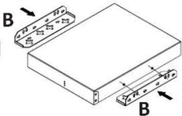
Kühlung
Quality & After Sales Manager
2 supports de type A
2 supports de type B
natural_image
Technical line drawing of a mechanical assembly with two vertical supports and a rectangular plate (no text or symbols)natural_image
Technical diagram of a mechanical assembly with two labeled components (A), showing mounting flanges and a central rectangular block (no text or symbols present)natural_image
Isometric line drawing of a rectangular electronic device with labeled ports (no text or symbols beyond basic labels)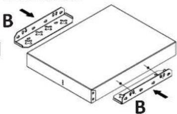
Refroidissement
Quality & After Sales Manager

natural_image
Technical line drawing of a mechanical assembly with two vertical supports and a rectangular plate (no text or symbols)natural_image
Technical diagram of a mechanical assembly with labeled components A and B, showing mounting flanges and a rectangular block (no text or symbols beyond labels)natural_image
Isometric line drawing of a rectangular electronic device with a labeled component (no text or symbols)
Enfriamiento
Quality & After Sales Manager
natural_image
Technical line drawing of a mechanical assembly with mounting flanges and a rectangular block (no text or symbols)natural_image
Technical diagram of a mechanical assembly with labeled components A and B, showing mounting flanges and housing (no text or symbols beyond labels)Quality & After Sales Manager

Scandicci
كانون الثاني 2022
natural_image
Technical line drawing of a mechanical assembly with two labeled components (A), showing mounting brackets and alignment features without any text or symbols.natural_image
Technical line drawing of a rectangular electronic device with two labeled components (B), showing internal structure and mounting holes (no text or symbols present)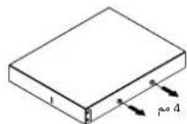
natural_image
Isometric line drawing of a rectangular electronic device with a small internal component and mounting holes (no text or symbols)B
الترتيب
natural_image
Technical line drawing of a mechanical assembly with mounting brackets (no text or symbols)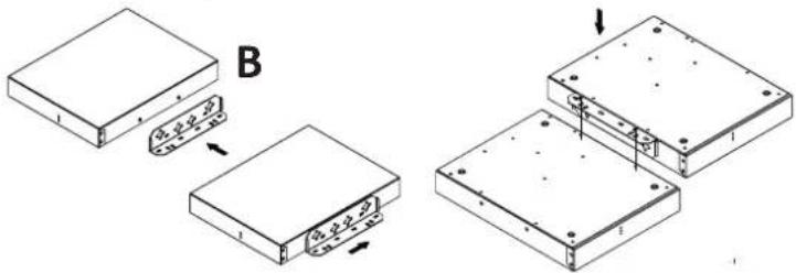
الخطوة 2 - المعايرة
Quality & After Sales Manager

natural_image
Technical line drawing of a mechanical assembly with mounting flanges and a rectangular plate (no text or symbols)Quality & After Sales Manager

仅限法规遵从性问题:compliance@powersoft.it
预备操作
包装清单
箱内含有:
1个Mezzo放大器
块连接器
2个支架A
2个支架B
螺钉(用于固定支架)
3条电源线
1个L形T8键
1个输出插头固定器
1个壁挂式钻孔模板表
位置
将放大器安装在允许空气交换的位置。
natural_image
Technical line drawing of a mechanical assembly with mounting brackets (no text or symbols)| LED | Color | Lighting | Description |
| Status | Green Solid ON Amplifier on and operational | ||
| Blue Low Intensity In standby | |||
| Red Solid ON Hardware fault | |||
| Network | Yellow | Solid ON | Temperature warning |
| Green Solid ON Ethernet up and operational | |||
| Blue Solid ON Connected to remote control | |||
| Signal | Green Solid ON Analogue input signal present | ||
| Yellow | Solid ON | Limiting in one or more channels | |
| Blue | Solid ON | Dante/AES67 input signal present | |
| Switched | Cyan | Solid ON | Both analogue and Dante/AES67 input signals present |
| Green | Solid ON | 'Switched' ethernet operation mode enabled | |
| OFF | - | 'Split' ethernet operation mode enabled | |
| Status Network Signal | All Cyan | All Blinking | Amplifier selected in ArmoníaPlus or blinking command triggered. |
Auto configuration LED feedback
| LED | Color | Description |
| Green | Measurement Successful - All parameters are set | |
| Yellow | Open Load Detected - No new parameter values are saved | |
| Red | Warnings - Hardware fault or output short-circuits detected. The output channel is muted | |
| Blue | Non-standard Impedance Curves - Impedance curve presents unclear peaks or other inconsistencies | |
| Cyan | Power Limitation Reached - Thermal measurement determines the load is above the amplifier specs |
Maximum Voltage Selection
| LED | Color | Lighting | Description | |
| 70V | ● | Green | Solid ON | 70V Selected |
| 100V | ∅ | OFF | - | |
| 70V | ∅ | OFF | - | 100V Selected |
| 100V | ● | Green | Solid ON | |
| 70V | ● | Green | Solid ON | 25V Selected |
| 100V | ● | Green | Solid ON | |
Pushbutton LED Chart - Amplifier ON
| LED | Color | Lighting | Description |
| Status | OFF | - | Push button pressed for more than 2s. |
| Network | OFF | - | |
| Signal | Purple | Solid ON | Auto configuration ready to be triggered following button release. |
| Status | OFF | - | Push button pressed for more than 5s. |
| Network | Cyan | Solid ON | Ethernet operation mode ready to be changed following push button release. |
| Signal | OFF | - |
Rear Panels
2 Channel Versions

AC Mains Connector
1 IEC 10A
Output
2 CH2 - CH1 Outputs
5 CH4 - CH3 Line Level Balanced Outputs
Input
3 CH4 - CH3 Balanced Inputs
4 CH2 - CH1 Unbalanced Inputs
GPIO Terminals
6 Multipurpose GPIO
Control & Monitoring
7 Amplifier State LEDs - Switched/Split mode LED (A+ & AD)
8 Pushbutton
Network Connectors
9 1 X RJ45 Fast Ethernet connector (Mezzo A Version)
10 2 X RJ45 Fast Ethernet connector (Mezzo A+ & AD Version)
4 Channel Versions

AC Mains Connector
1 IEC 10A
Output
2 CH4 - CH3 Outputs
3 CH2 - CH1 Outputs
GPIO Terminals
7 Multipurpose GPIO
Control & Monitoring
8 Amplifier State LEDs - Switched/Split mode LED (A+ & AD)
9 Pushbutton
Input
4 CH4 - CH3 Balanced Inputs
5 CH2 - CH1 Unbalanced Inputs
6 CH2 - CH1 Balanced Inputs
Network Connectors
10 1 X RJ45 Fast Ethernet connector (Mezzo A Version)
11 2 X RJ45 Fast Ethernet connector (Mezzo A+ & AD Version)
Powersoft HUMAN AUDIO EXPERIENCE
POWERSOFT S.P.A.
Via E. Conti, 5 - Scandicci (FI) 50018 - Italy
support@powersoft.com
+39 055 73 50 230
+39 055 73 56 235
- Important Safety Instructions
- Common symbols and meanings
- Safety Warnings
- Warranty and Technical Service
- EC Declaration Of Conformity
- Regulatory Compliance Statements
- Europe
- USA
- FCC Supplier's Declaration of Conformity
- FCC Compliance Statement
- Canada
- Canadian Caution
- Radiation Exposure Statement
- EN
- Preliminary operations
- Package list
- Location
- Cooling
- Set-up and Operation
- Power State
- DSP and matrix configuration
- Automatic configuration
- Factory Reset
- Routing and control via GPI
- Raffreddamento
- Kühlung
- Refroidissement
- Enfriamiento
- 预备操作
- 包装清单
- 位置
- Rear Panels
- AC Mains Connector
- Output
- Input
- GPIO Terminals
- Control & Monitoring
- Network Connectors
- Powersoft HUMAN AUDIO EXPERIENCE
Brand : Powersoft
Model : Mezzo 322
Category : Receiver