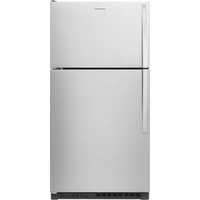
CRTW2154SB - Fridge Crosley - Free user manual and instructions
Find the device manual for free CRTW2154SB Crosley in PDF.


| Brand | Crosley |
| Model | CRTW2154SB |
| Product Type | Refrigerator with Freezer |
| Electrical Supply | 115 V AC, 60 Hz, 15-20 A (dedicated circuit recommended) |
| Dimensions (clearances) | Width: +1.25 cm each side; Height: 3.81 cm above; Depth: 2.54 cm at rear |
| Operating Ambient Temperature | 13°C to 43°C (optimal 15°C to 32°C) |
| Water Pressure for Ice Maker | 207 to 827 kPa (30-120 psi) |
| Freezer | Yes, separate compartment with adjustable shelf |
| Ice Maker | Automatic (built-in or kit) |
| Lighting | LED (sealed or bulb); max 40 W for incandescent bulb |
| Refrigerator Shelves | Tempered glass, adjustable (slide-out) |
| Door Bins | Removable, includes can caddy and egg tray |
| Meat/Deli Drawer | Yes, with removable cover |
| Crisper Drawer | With humidity control (Low/High) |
| Air Filter | Yes, replace every 6 months (ref. W10311524) |
| Door Reversal | Possible (reversal kit included) |
| Cleaning | Unplug before cleaning; mild detergent; stainless steel (Affresh® product) |
| Defrost | Automatic (no manual defrost) |
| Leveling Legs | 2 adjustable front legs |
| Warranty | Refer to Quick Start Guide for contact information |
Frequently Asked Questions - CRTW2154SB Crosley
User questions about CRTW2154SB Crosley
0 question about this device. Answer the ones you know or ask your own.
Ask a new question about this device
Download the instructions for your Fridge in PDF format for free! Find your manual CRTW2154SB - Crosley and take your electronic device back in hand. On this page are published all the documents necessary for the use of your device. CRTW2154SB by Crosley.
USER MANUAL CRTW2154SB Crosley
Changing the Light Bulbs....4
Vacations 5
Moving 5
INSTALLATION INSTRUCTIONS 5
Unpack the Refrigerator 5
Location Requirements 6
Electrical Requirements 6
Water Supply Requirements.... 6
Connect the Water Supply 7
Install Air Filter 8
REFRIGERATOR DOORS.... 9
Door and Handle Instructions 9
Remove Doors and Hinges 9
Reverse Doors and Hinges (optional) 10
Replace Doors and Hinges 13
Install Doors Handles.... 13
Final Steps 15
Adjust the Doors 15
REFRIGERATOR AND FREEZER FEATURES.... 15
Refrigerator Shelves.... 15
Freezer Shelf 16
Door Rails or Trivets 16
Can Racks and Bins (on some models) 17
Deli or Meat Drawer.... 17
Crisper 17
Utility Compartment.... 18
Ice Maker 18
Operating Instructions.... 19
SÉCURITÉ DU RÉFRIGÉRATEUR 20
ENTRETIEN ET RÉPARATION 21
Nettoyage 21
Your safety and the safety of others are very important.
We have provided many important safety messages in this manual and on your appliance. Always read and obey all safety messages.

This is the safety alert symbol.
This symbol alerts you to potential hazards that can kill or hurt you and others.
All safety messages will follow the safety alert symbol and either the word "DANGER" or "WARNING." These words mean:
DANGER
WARNING
All safety messages will tell you what the potential hazard is, tell you how to reduce the chance of injury, and tell you what can happen if the instructions are not followed.
You can be killed or seriously injured if you don't immediately follow instructions.
You can be killed or seriously injured if you don't follow instructions.
IMPORTANT SAFETY INSTRUCTIONS
WARNING: To reduce the risk of fire, electric shock, or injury to persons when using your appliance, follow basic precautions, including the following:
■ Children should be supervised to ensure that they do not play with the appliance.
■ This appliance is not intended for use by persons (including children) with reduced physical, sensory, or mental capabilities, or lack of experience and knowledge, unless they have been given supervision or instruction concerning use of the appliance by a person responsible for their safety.
■ Do not use an extension cord.
If power supply cord is damaged, it must be replaced by the manufacturer, its service agent, or a similarly qualified person in order to avoid a hazard.
■ Connect to portable water supply only.
■ This appliance is intended to be used in household and similar applications such as: staff kitchen areas in shops, offices, and other working environments; farm houses and by clients in hotels, motels, and other residential-type environments; bed and breakfast-type environments; and catering and similar non-retail applications.
■ Do not store explosive substances such as aerosol cans with a flammable propellant in this appliance.
■ Use the new hose-sets supplied with the appliance and that old hose-sets should not be reused.
■ Do not use replacement parts that have not been recommended by the manufacturer (e.g., parts made at home using a 3D printer).
- Keep ventilation openings, in the appliance enclosure or in the built-in structure, clear of obstruction.
■ Do not use mechanical devices or other means to accelerate the defrosting process, other than those recommended by the manufacturer.
■ Do not damage the refrigerant circuit.
■ Do not use electrical appliances inside the food storage compartments of the appliance, unless they are of the type recommended by the manufacturer.
■ Ice Maker kit can be added to some models. See serial tag inside the food compartment of appliance for ice maker kit model information.
A qualified service technician must install the water line and ice maker. See installation instructions supplied with ice maker kit for complete details.
■ Do not locate multiple portable socket-outlets or portable power supplies at the rear of the appliance.
■ When positioning the appliance, ensure the supply cord is not trapped or damaged.
SAVE THESE INSTRUCTIONS
Proper Disposal of Your Old Refrigerator
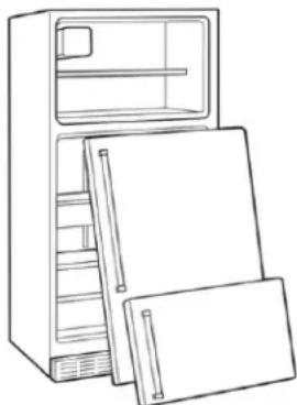
WARNING: Risk of child entrapment. Before you throw away your old refrigerator or freezer:
■ Take off the doors.
■ Leave the shelves in place so that children may not easily climb inside.
WARNING
Suffocation Hazard
Remove doors or lid from your old appliance.
Failure to do so can result in death or brain damage.
IMPORTANT: Child entrapment and suffocation are not problems of the past. Junked or abandoned refrigerators are still dangerous even if they will sit for "just a few days." If you are getting rid of your old refrigerator, please follow these instructions to help prevent accidents.
Important information to know about disposal of refrigerants:
Dispose of refrigerator in accordance with federal and local regulations. Refrigerants must be evacuated by a licensed, EPA-certified refrigerant technician in accordance with established procedures.
natural_image
Line drawing of a refrigerator with open doors and shelves (no text or symbols)MAINTENANCE AND CARE
Cleaning
WARNING
Explosion Hazard
Risk of Fire or Explosion.
Flammable Refrigerant Used.
Do Not Use Mechanical Devices to Defrost Refrigerator. Do Not Puncture Refrigerant Tubing.
Both the refrigerator and freezer sections defrost automatically. However, clean both sections about once a month to avoid buildup of odors. Wipe up spills immediately.
IMPORTANT:
■ Because air circulates between both sections, any odors formed in one section will transfer to the other. You must thoroughly clean both sections to eliminate odors. To avoid odor transfer and drying out of food, wrap or cover foods tightly.
■ For stainless steel models, stainless steel is corrosion resistant and not corrosion-proof. To help avoid corrosion of your stainless steel, keep your surfaces clean by using the following cleaning instructions.
To Clean Your Refrigerator:
NOTE: Do not use abrasive or harsh cleaners such as window sprays, scouring cleansers, flammable fluids, muriatic acid, cleaning waxes, concentrated detergents, bleaches or cleansers containing petroleum products on exterior surfaces (doors and cabinet), plastic parts, interior and door liners, or gaskets. Do not use paper towels, scouring pads, or other harsh cleaning tools.
- Unplug refrigerator or disconnect power.
- Using a clean sponge or soft cloth and a mild detergent in warm water, hand-wash, and rinse removable parts and interior surfaces thoroughly. Dry thoroughly with a soft cloth.
- Clean the exterior surfaces.
NOTE:
■ When cleaning stainless steel, always wipe in the direction of the grain to avoid cross-grain scratching.
■ To keep your stainless steel refrigerator looking like new and to remove minor scuffs or marks, it is suggested that you use the manufacturer's approved Stainless Steel Cleaner and Polish. To order, use the following parts: affresh® Stainless Steel Cleaner: Part #W10355016 affresh® Stainless Steel Wipes: Part #W10355049 affresh® Kitchen & Appliance Cleaner: Part #W10355010
■ Stainless Steel Cleaner and Polish is for stainless steel only. Do not allow the Stainless Steel Cleaner to come into contact with any plastic parts such as the trim pieces, dispenser covers or door gaskets. If unintentional contact does occur, clean plastic part with a sponge and a mild detergent in warm water. Dry thoroughly with a soft cloth.
- There is no need for routine condenser cleaning in normal home operating environments. If the environment is particularly greasy or dusty, or there is a significant pet train in the home, the condenser should be cleaned every 2 to 3 months to ensure maximum efficiency. If you need to clean the condenser:
WARNING
Explosion Hazard
Risk of Fire or Explosion due to Puncture of Refrigerant Tubing;
Follow Handling Instructions Carefully.
Flammable Refrigerant Used.
■ Pull refrigerator out away from the wall. See “Unpack the Refrigerator.”
■ Remove the base grille.
■ Vacuum coils when they are dusty or dirty.
■ Replace the base grille when finished.
■ Roll refrigerator back into place. Make sure to leave 1" (2.5 cm) between the cabinet back and the wall.
■ Check to see that the refrigerator is level.
- Plug in refrigerator or reconnect power.
Changing the Light Bulbs
IMPORTANT: The lights in both the refrigerator and freezer compartments use LEDs. If the lights do not illuminate when the door or drawer is opened, call for assistance or service. Refer to the Quick Start Guide for contact information. The lighting system in this appliance may consist of:
■ Sealed LED modules
■ LED Bulbs
■ Incandescent Bulbs
■ or a combination of the above.
NOTE: If your product has a sealed LED module, call for assistance or service. Refer to the Quick Start Guide for contact information.
IMPORTANT:
■ Depending on your model, the light bulb in your new refrigerator may use LED technology. If your model uses LED, lighting and the light does not illuminate when the refrigerator door is opened, call for assistance or service.
■ Some LED replacement bulbs are not recommended for wet/damp environments. The refrigerator and freezer compartments are considered to be wet/dam environments. If using a brand of LED bulb other than the recommended LED bulb listed below, before installation, read and follow all instructions on the LED packaging.
If an incandescent bulb is used to replace an LED bulb, use only incandescent bulbs for household appliances with a maximum of 40 W.
CHANGING THE LIGHT BULB
- Unplug refrigerator or disconnect power.
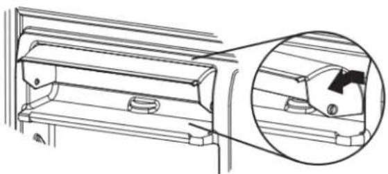
- The light bulb is located behind the Temperature control on most models.
- Remove the light shield (if applicable) as shown below.
- Remove and replace the light bulb as shown below.
- Replace the light shield (if applicable).
- Plug in refrigerator or reconnect power.
natural_image
Technical line drawing of a mechanical component or housing (no text or symbols)To Remove and Replace Light Bulb:
- Reach behind the control panel and unscrew the bulb.
- Replace the bulb with a 40 W maximum appliance bulb.
natural_image
Technical diagram showing a mechanical component with an inset close-up view (no text or symbols)- Remove the light shield by squeezing in on the sides and pulling it straight down.
- Remove the light bulb and replace it with an appliance bulb of the same size and shape.
NOTE: To replace with an LED light bulb, order part number W10565137 (3.6 W).
natural_image
Diagram of a car interior showing hand positioning and directional arrow (no text or symbols)- Remove the light shield by squeezing in on the sides and pulling it straight down.
- Remove the light bulb and replace it with an appliance bulb of the same size and shape.
NOTE: To replace with an LED light bulb, order part number W10565137 (3.6 W).
FREEZERLIGHT

natural_image
Diagram of a bowl with curved layers and directional arrows indicating flow or movement (no text or symbols)1.Slidethelightshieldtowardthebackofthecompartmentto releaseitfromthelightassembly.
- Removethelightbulbandreplaceitwithanappliancebulb ofthesamesizeandshape. NOTE: ToreplacewithanLEDlightbulb, orderpartnumber W10574850(2.0W).
Vacations
IfYouChoosetoLeavetheRefrigeratorOnWhileYou're Away:
-
Useupanyperishablesandfreezerotheritems.
-
If your refrigerator has an automatic cemaker and is connected to the household watersupply, turn off the water supply to there refrigerator. Property damage can occur if the watersupply is not turned off.
-
If you have an automatic icemaker, turn off the icemaker. NOTE: Raisethewireshut-offarmtoOff(up)position.
-
Emptytheicebin.
IfYouChoosetoTurnOfftheRefrigeratorBeforeYouLeave:
-
Remove all food from there refrigerator.
-
If your refrigerator has an automaticicemaker:
■ Turnoffthewatersupplytotheicemakeratleastoneday aheadoftime.
■ Whenthelastloadoficedrops, raisethewireshut-offarm totheOff(up)position.
-
Turnoff the Temperature control(s). See "Using the Controls" in the Quick kStartGuide.
-
Clean refrigerator, wipeit, and drywell.
-
Taperubberorwoodblockstothetopsofbothdoorstoprop themopenfarenoughforairtogetin. Thisstopsodorand moldfrombuildingup.
Moving
Whenyouaremovingyourrefrigeratortoanewhome,follow thesestepstopprepareitforthemove.
- If your refrigerator has an automaticicemaker:
■ Turnoffthewatersupplytotheicemakeratleastoneday aheadoftime.
■ Disconnectthewaterlinefromthebackoftherefrigerator.
■ Whenthelastloadoficedrops, raisethewireshut-offarm totheOff(up)position.
-
Remove all food from there refrigerator and pack all frozen food indryce.
-
Emptytheicebin.
-
Turnoff the Temperature control(s). See "Using the Controls" in the Quick Start Guide.
-
Unplugrefrigerator
-
Clean refrigerator, wipeit, and drywell.
-
Takeoutallremovableparts,wrapthemwell,andtapethem togethersotheydon'tshiftandrattleduringthemove.
-
Dependingonthemodel, raisethefrontoftherefrigeratorsoit rollsmoreeasily, orraisethelevelinglegssotheydon't scrapethefloor. See "Adjus theDoors" or "DoorRemoval, LevelingandAlignment" intheonlineFeatureGuide.
-
Tapethedoorsclosedandtapethepowercordtothebackoftherefrigerator.
Whenyougettoyournewhome,puteverythingbackandreferto the "InstallationInstructions"forpreparationinstructions.Also,if yourrefrigeratorhasanautomaticicemaker,rememberto reconnectthewatersupplytotherfrigerator.
INSTALLATIONINSTRUCTIONS
UnpacktheRefrigerator
WARNING
ExcessiveWeightHazard
Usetwoormorepeopletomoveandinstalloruninstall appliance.
Failuretodosocanresultinbackorotherinjury.
RemovethePackaging
IMPORTANT: Donotremovethewhitefoamairreturninsertfrom behindthecontrolpanelontheceilingoftherefrigerator. If the insertisremoved, icemaymigratedownfromthefreezerand causeiciclestoform.
■ Removetapeandglueresiduefromsurfacesbeforeturningon therefrigerator.Rubasmallamountofliquiddishsoapover theadhesivewithyourfingers.Rinsewithwarmwateranddry withasoftcloth.
NOTE: Donotusesharpinstruments, rubbingalcohol, flammablefluids, or abrasivecleanerstoremovetapeorglue. Theseproductscandamagethesurfaceofyourrefrigerator. Formoreinformationsee"RefrigeratorSafety."
■ Disposeof/recycleallpackagingmaterials.
When Moving Your Refrigerator:
Yourrefrigeratorisheavy.Whenmovingtherefrigeratorfor cleaningorservice,besuretocoverthefloorwithcardboardor hardboardtoavoidfloordamage.Alwayspulltherefrigerator straightoutwhenmovingit.Donotwiggleor"walk"the refrigeratorwhentryingtomoveit,asfloordamagecouldoccur.
CleanBeforeUsing
Afteryouremoveall ofthepackagingmaterials,cleantheinside ofyourrefrigeratorbeforeusingit.Seethecleaninginstructionsin the"MaintenanceandCare"section.
Importantinformationtoknowaboutglassshelvesand covers:
Donotcleanglassshelvesorcoverswithwarmwaterwhenthey arecold.Shelvesandcoversmaybreakifexposedtosudden temperaturechangesorimpact,suchasbumping.Tempered glassisdesignedtoshatterintomanysmall,pebble-sizepieces. Thisisnormal.Glassshelvesandcoversareheavy.Useboth handswhenremovingthemtoavoiddropping.
Location Requirements
WARNING
Explosion Hazard
Keep flammable materials and vapors, such as gasoline, away from appliance.
Use nonflammable cleaner.
Failure to do so can result in death, explosion, or fire.
IMPORTANT: This refrigerator is designed for indoor, household use only.
To ensure proper ventilation for your refrigerator, allow 1/2" (1.25 cm) of space on each side. Allow (3.81 cm) of space between overhead cabinets and refrigerator top. Allow at least 1 (2.54 cm) between back of cabinet and the wall. If your refrigerator has an ice maker, allow extra space at the back for the water connections.
NOTE: This refrigerator is intended for use in a location where temperature ranges from a minimum of 55^ F ( 13^ C) to a maximum of 110^ F ( 43^ C). The preferred room temperature range for optimum performance, which reduces electricity usage and provides superior cooling, is between 60^ F ( 15^ C) and 90^ F ( 32^ C). It is recommended that you do not install the refrigerator near a heat source, such as an oven or radiator.

Electrical Requirements
WARNING
Electrical Shock Hazard
Plug into a grounded 3 prong outlet.
Do not remove ground prong.
Do not use an adapter.
Do not use an extension cord.
Failure to follow these instructions can result in death, fire, or electrical shock.
Before you move your refrigerator into its final location, it is "important to make sure you have the proper electrical connection.
the supply cord is damaged, it must be replaced by the manufacturer or its service agent or a similarly qualified person. Do not use a cord that shows cracks or abrasion damage along its length or at either the plug or connector end.
Recommended Grounding Method
A 115 V, 60 Hz AC only 15 A or 20 A fused, grounded electrical supply is required. It is recommended that a separate circuit serving only your refrigerator be provided. Use an outlet that cannot be turned off by a switch. Do not use an extension cord.
NOTE: Before performing any type of installation, cleaning, or removing a light bulb, turn the refrigerator to Off. Depending on your model, turn the refrigerator control to the word Off, or press the refrigerator down arrow touch pad until a dash (−) appears in refrigerator displays. Disconnect the refrigerator from the electrical source. When you are finished, reconnect the refrigerator to the electrical source and reset the temperature controls to the desired setting. See "Using the Controls" in the Quick Start Guide.
Water Supply Requirements
Read all directions before you begin.
IMPORTANT:
■ Connect to potable water supply only.
Do not use with water that is microbiologically unsafe or of unknown quality without adequate disinfection before or after the system. Systems certified for cyst reduction may be used on disinfected waters that may contain filterable cysts.
■ If you turn the refrigerator on before the water line is connected, turn off the ice maker.
■ All installations must meet local plumbing code requirements.
■ Use copper or PEX tubing and check for leaks. Install copper or PEX tubing only in areas where the household temperatures will remain above freezing.
TOOLS NEEDED: Flat-blade screwdriver, 7/16" and 1/2" open-end wrenches or 2 adjustable wrenches, 1/4" nut driver and drill bit, cordless drill. Gather the required tools and parts before starting installation. Read and follow the instructions provided with any tools listed.
NOTE: Your refrigerator dealer has a kit available with a 1/4" 6. (6.35 mm) saddle-type shut-off valve, a union, and copper or PEX tubing. Before purchasing, make sure a saddle-type valve complies with your local plumbing codes. Do not use a piercing-type or 3/16" (4.76 mm) saddle valve which reduces water flow and clogs more easily.
Water Pressure
A cold water supply with water pressure of between 30 psi and 120 psi (207 kPa and 827 kPa) is required to operate the ice maker. If you have questions about your water pressure, see "Troubleshooting" online or call a licensed, qualified plumber.
Reverse Osmosis Water Supply
If a reverse osmosis water filtration system is connected to your cold water supply, the water pressure to the reverse osmosis system needs to be a minimum of 40 psi to 60 psi (276 kPa to 414 kPa). If the ice maker is still not operating properly:
- Check to see whether the sediment filter in the reverse osmosis system is blocked. Replace the filter if necessary.
- Allow the storage tank on the reverse osmosis system to refill, after heavy usage.
If you have questions about your water pressure, see "Troubleshooting" online or call a licensed, qualified plumber.
Connect the Water Supply
Read all directions before you begin.
IMPORTANT: If you turn on the refrigerator before the water line connected, turn off the ice maker to avoid excessive noise or damage to the water valve.
Connect to Water Line
- Unplug refrigerator or disconnect power.
- Turn Off main water supply. Turn On nearest faucet long enough to clear line of water.
- Locate a 1/2" to 1/4" (1.27 cm to 3.18 cm) vertical cold water pipe near the refrigerator.
IMPORTANT:
■ Make sure it is a cold water pipe.
■ Horizontal pipe will work, but drill on the top side of the pipe, not the bottom. This will help keep water away from the drill and normal sediment from collecting in the valve.
-
Determine the length of copper or PEX tubing you will need. Measure from the connection on lower-left rear of refrigerator to the water pipe. Add 7 ft (2.1 m) to allow for cleaning. Use 1/4" (6.35 mm) O.D. (outside diameter) copper or PEX tubing. Be sure both ends of copper or PEX tubing are cut square.
-
Using a cordless drill, drill a 1/4" hole in the cold water pipe you have selected.
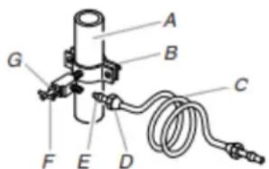
A. Cold water pipeE. Compression sleeve
B. Pipe clamp F. Shut-off valve
C. Copper or PEX ^G . Packing nut tubing
D. Compression nut
- Fasten the Shut-off valve to the cold water pipe with the pipe EX clamp. Be sure the outlet end is solidly in the 1/4" (6.35 mm) drilled hole in the water pipe and that the washer is under the pipe clamp. Tighten the packing nut. Tighten the pipe clamp screws slowly and evenly so washer makes a watertight seal. Do not overtighten or you may crush the copper or PEX tubing.
- Slip the compression sleeve and compression nut on the copper or PEX tubing as shown (PEX tubing has compression sleeves and compression nuts preinstalled.) Insert the end of the tubing into the outlet end squarely as far as it will go. Screw compression nut onto outlet end with adjustable wrench. Do not overtighten.
- Place the free end of the tubing in a container or sink, and turn On the main water supply. Flush the tubing until water is clear. Turn Off the Shut-off valve on the water pipe. Coil the copper or PEX tubing.
Connect to Refrigerator
NOTE: On kit models, assemble water valve to refrigerator according to kit instructions.
Style 1
- Unplug refrigerator or disconnect power.
- Attach the copper tube to the valve inlet using a compression nut and sleeve as shown. Tighten the compression nut. Do not overtighten.
- Use the tube clamp on the back of the refrigerator to secure the is the tubing to the refrigerator as shown. This will help avoid damage to the tubing when the refrigerator is pushed back against the wall.
- Turn On Shut-off valve.
- Check for leaks. Tighten any connections (including connections at the valve) or nuts that leak.
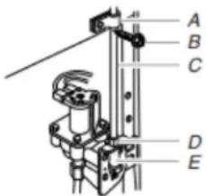
A. Tube clamp D. Compression nut
B. Tube clamp e. Valve inlet screw
C. Copper or PEX tubing
- The ice maker is equipped with a built-in water strainer. If your water conditions require a second water strainer, install it in the 1/4" (6.35 mm) water line at either tube connection. Obtain a water strainer from your nearest appliance dealer.
NOTE: On kit models, assemble water valve to refrigerator according to kit instructions.
Style 2
- Unplug refrigerator or disconnect power.
- Disconnect the tube clamp on the back of the product and insert the copper or PEX tubing through the clamp as shown.
-
Attach the copper or PEX tube to the valve inlet using a compression nut and sleeve as shown.
-
Tighten the compression nut. Do not overtighten. Reattach the Install Air Filter
tube clamp and tube to the back of the cabinet.
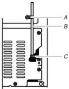
A. Tube clamp
C. Compression nut
B. Copper or PEX tubing
- Turn On Shut-off valve. Check for leaks. Tighten any connections (including connections at the valve) or nuts that leak.
- The ice maker is equipped with a built-in water strainer. If y water conditions require a second water strainer, install it in the 1/4" (6.35 mm) water line at either tube connection. Obt a water strainer from your nearest appliance dealer.
Complete the Installation
WARNING
Electrical Shock Hazard
Plug into a grounded 3 prong outlet.
Do not remove ground prong.
Do not use an adapter.
Do not use an extension cord.
Failure to follow these instructions can result in death, fire, or electrical shock.
- Plug into a grounded 3-prong outlet.
NOTE: Allow 24 hours to produce the first batch of ice. Discard the first three batches of ice produced. Allow 3 days to completely fill ice container.
On some models, your refrigerator's accessory packet includes an air filter, which must be installed prior to use. On some models, the air filter is already installed at the factory. To order a replacement air filter, use part number W10311524.

natural_image
Illustration of a rectangular electronic component with grid-like internal structure (no text or symbols)The air filter reduces the buildup of odors. This helps to maintain a cleaner environment inside the refrigerator.
Installing the Air Filter
The filter should be installed behind the vented door, which is located (depending on your model) along either the rear or left interior wall near the top of the refrigerator compartment.
- Remove the air filter from its packaging. 2) Lift open the vented door.
- Snap the filter into place.
Air Filter Status Indicator
The filter comes with a status indicator, which should be activated and installed at the same time the air filter is installed.

- Place the indicator facedown on a firm, flat surface.
- Apply pressure to the bubble on the back of the indicator, until the bubble pops to activate the indicator.
- Lift open the vented air filter door. On some models, there are notches behind the door.
On models with notches:
■ Slide the indicator down into the notches, facing outward.
NOTE: The indicator will not easily slide into the notches if the rear bubble has not been popped.
■ Close the air filter door, and check that the indicator is visible through the rectangular hole in the door.
On models without notches:
■ Store the indicator in a visible place you will easily remember either inside the refrigerator or elsewhere in your kitchen or home.
Replacing the Air Filter
The disposable air filter should be replaced every 6 months, when the status indicator has completely changed from white to red.
- Remove the old air filter by squeezing in on the side tabs.
- Remove the old status indicator.
- Install the new air filter and status indicator using the instructions in the previous sections.
REFRIGERATOR DOORS
Door and Handle Instructions
Depending on the width of your doorway, you may need to remove the doors to move the refrigerator into your home. Also, the door hinges are factory installed on the right-hand side. If you want the door to open from the other direction, you must reverse the door swing.
WARNING
Electrical Shock Hazard
Disconnect power before removing doors.
Failure to do so could result in death or electrical shock.
IMPORTANT:
■ Before you begin, turn the refrigerator control off. Unplug refrigerator or disconnect power. Remove food and any adjustable door or utility bins from doors.
If you are only removing and replacing the doors, see the "Remove Doors and Hinges" and "Replace Doors and Hinges" sections.
If you choose to reverse the door swing, a Reversibility Kit, which includes a new brand badge and hole plugs, is available.
Tools Needed: 5/16" hex-head socket wrench, #2 Phillips screwdriver, flat-blade screwdriver, 5/16" open-end wrench, flat 2" putty knife
Remove Doors and Hinges
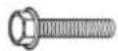
5/16" Hex-Head Top Hinge Screw
- Unplug refrigerator or disconnect power.
- Using a hex-head socket wrench, remove the three 5/16" hex-head hinge screws from the top hinge and lift up to remove the hinge.
NOTE: Provide additional support for the door while the hinges are being moved. Do not depend on the door magnets to hold the door in place while you are working.
| Top Hinge Style 1 | |
| A. 5/16" Hex-head hinge screws | C. Hinge pin |
| B. Top hinge D. Spacer | |
Top Hinge Style 2
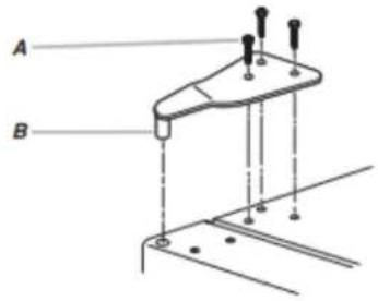
A. 5/16" Hex-head hinge screws
B. Top hinge
- Lift the freezer door off of the center hinge and set it aside.
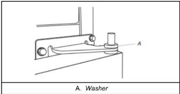
- Remove the washer from the top of the Center Hinge pin.
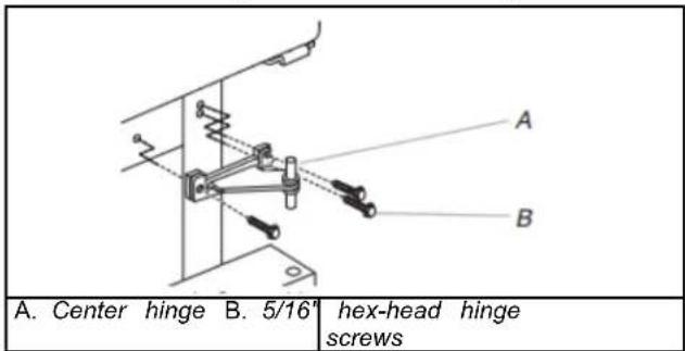
- Using a hex-head socket wrench, remove the three screws from the center hinge and remove the hinge. Set aside.
WARNING
Excessive Weight Hazard
Use two or more people to lift the appliance door.
Failure to do so can result in back or other injury.
-
Lift the refrigerator door off of the bottom hinge and set it aside.
-
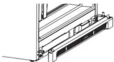
Remove the base grille from the bottom front of the refrigerator. Check your model for applicability.
natural_image
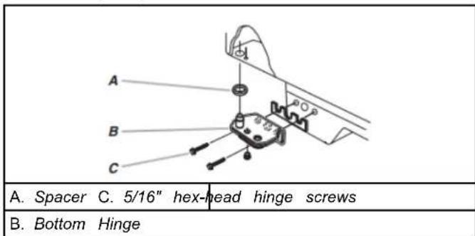
Technical line drawing of a mechanical assembly with no visible text or symbols- Remove the parts for the bottom hinge as shown in the Bottom Hinge graphics.
Bottom Hinge Style 1

Bottom Hinge Style 2
Reverse Doors and Hinges (optional) _3 .
IMPORTANT: If you want to reverse your doors so that they open in the opposite direction, follow these steps. If you are not reversing the doors, see "Replace Doors and Hinges."
Style 1 - Standard Door Models
Graphics follow these instructions.

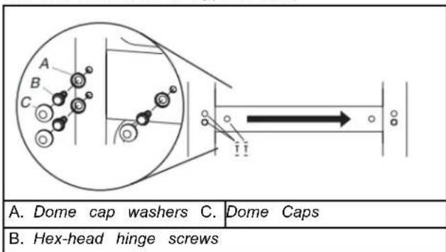
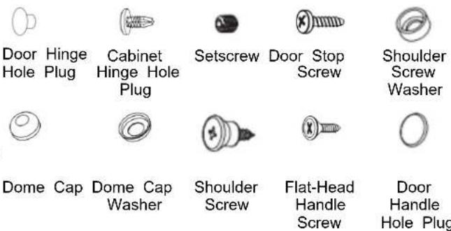
Door Stop Screw

Door Handle Sealing Screw

Dome Cap
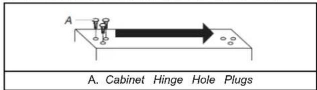
Cabinet Hinge Hole Plug

Door Handle Hole Plug
Cabinet
- Remove the three dome caps and the screws from handle side and move them to opposite side.
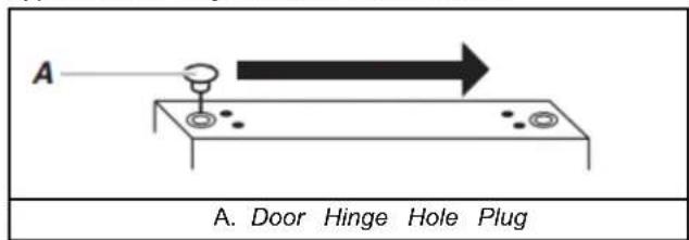
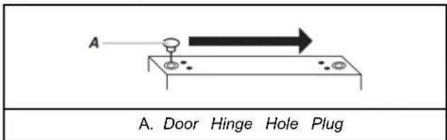
- Remove cabinet hinge hole plugs from cabinet top and move them to opposite side hinge holes as shown below.
Freezer Door
-
Remove the screw cover.
-
Remove the freezer handle assembly as shown below. Keep all parts together.

- Remove door hinge hole plug from freezer door. Move to open opposite side hinge hole as shown below.
- Remove the brand badge using the plastic tool (provided). Replace it with the badge provided in the Reversibility Kit located inside the crisper drawer. For proper placement, see the Brand Badge Placement template (the last page of this manual).
NOTES:
■ To avoid scratching the finish, do not use a sharp or metallic object to pry the brand badge from the door.
■ Rub a small amount of liquid dish soap over any adhesive residue with your fingers. Rinse the door with warm water and dry with a soft cloth.
-
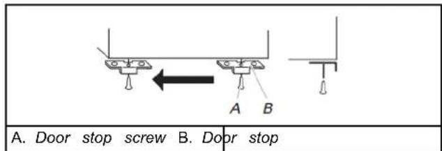
Remove door stop. Move to opposite side of refrigerator door as shown.
-
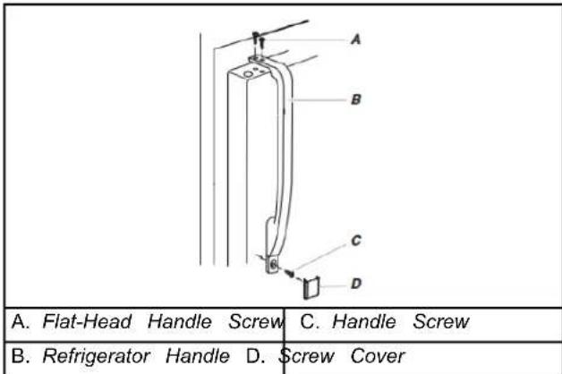
Refer to image in Step 2. Position freezer handle on opposite6. Remove door stop. Move to opposite side of refrigerator door side of the freezer door. First, drive the bottom two screws into as shown below.
handle. Align upper portion of handle and drive top screw into handle.
-
Tighten all screws. Set aside door until hinges and refrigerator compartment door are in place.
-
Replace screw cover. Refer to image in Step 2.
Refrigerator Door
- Remove the screw cover.
- Remove refrigerator handle assembly as shown below. Keep all parts together.
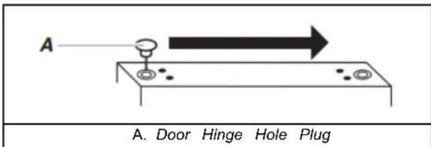
- Remove door hinge hole plug from refrigerator door. Move to opposite side hinge hole as shown below.
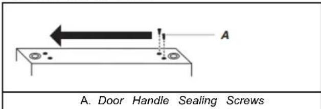
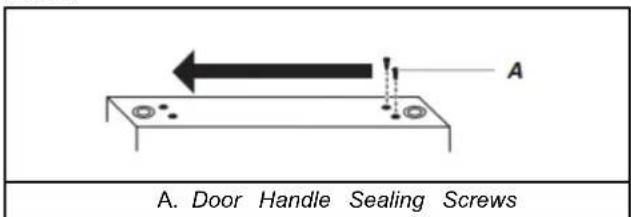
- Remove door handle sealing screws. Move to opposite side refrigerator door as shown.
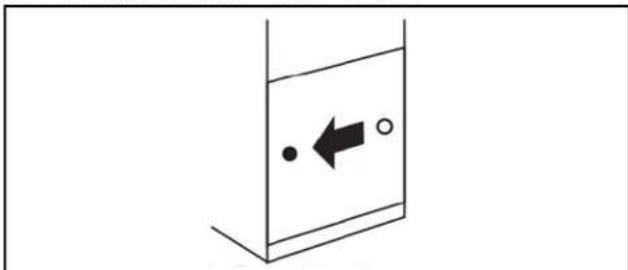
- Remove door handle hole plug and discard. Replace on opposite side with the door handle hole plug provided in the Reversibility Kit located in the crisper.
natural_image
Simple line drawing of a container with an arrow and two circles inside, no text or symbols present.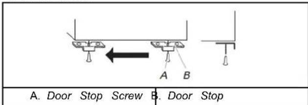
- Refer to image in Step 2. Position refrigerator handle on opposite side of the refrigerator door. First, drive top two screws in handle first. Align lower portion of handle and drive bottom screw into handle.
- Tighten all screws. Set aside refrigerator door until bottom hinge is installed on refrigerator.
- Replace screw cover.
Style 2 - Contour Door Models
Graphics follow these instructions.
Cabinet
- Remove the three dome caps and the screws from handle side and move them to opposite side.
- Using the three 5/16" hex-head hinge screws, insert two screws halfway into the holes, leaving space to insert the Center Hinge.
- Slide the center hinge, from the right, onto the screws, insert the third screw, and tighten all screws completely.
NOTE: Make sure the washers are in place on both the top and bottom pins of the center hinge.
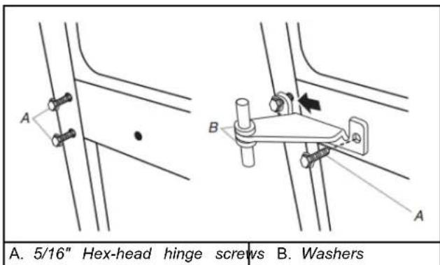
- Remove cabinet hinge hole plugs from the cabinet top and move them to opposite side hinge holes as shown below.

Freezer Door
- Remove the freezer door handle. Using a 1/8" hex key, loosen the setscrew located on the side of the handle. Pull the handle straight out from the door. Keep all parts together.
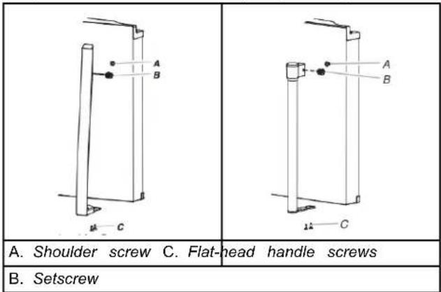
- Remove the brand badge using the plastic tool (provided). Replace it with the badge provided in the Reversibility Kit located inside the crisper. For proper placement, see the Brand Badge Placement template (the last page of this manual).
NOTES:
■ To avoid scratching the finish, do not use a sharp or metallic object to pry the brand badge from the door.
■ Rub a small amount of liquid dish soap over any adhesive residue with your fingers. Rinse the door with warm water and dry with a soft cloth.
- Remove door stop. Move to opposite side of freezer door as shown.
- Refer to image in Step 1. Install freezer handle again on opposite side of the freezer door.
- Tighten all screws. Set aside door until hinges and refrigerator compartment door are in place.
Refrigerator Door
- Remove the refrigerator door handle. Using a 1/8" hex key, loosen the setscrew located on the side of the handle. Pull the handle straight out from the door. Keep all parts together.
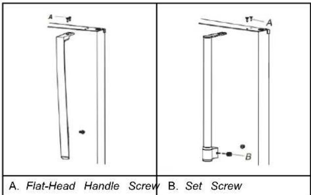
- Remove door hinge hole plug from refrigerator door. Move to opposite side hinge hole as shown below.
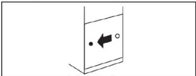
- Remove door handle hole plug and discard. Replace on opposite side with the door handle hole plug provided in the Reversibility Kit located in the crisper.
natural_image
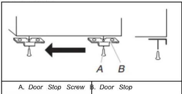
Simple line drawing of a container with an arrow and two dots, no text or symbols present- Remove door stop. Move to opposite side of refrigerator door as shown below.
- Refer to image in Step 1. Install refrigerator handle again on opposite side of the refrigerator door.
- Tighten all screws. Set aside refrigerator door until bottom hinge is installed on refrigerator.
Replace Doors and Hinges
NOTE: Graphic may be reversed if door swing is reversed.
- Replace the parts for the bottom hinge as shown. Tighten screws. Replace the refrigerator door.
NOTE: Provide additional support for the doors while the hinges are being moved. Do not depend on the door magnet to hold the doors in place while you are working.
Install Doors Handles
Tools Required
Parts Supplied:
■ Door handles (2)
■ Screws (4 or 6 depending n the model)
Set screws (2)
Tools Supplied:
- Measure the distance from the bottom of the refrigerator door ■ 1/8" Hex key (1) Keep for future use. (depending on the model) to the floor. The distance should be approximately 3 (88 mm).
NOTE: If necessary, loosen the bottom hinge, without Tools Needed: removing the screws, adjust the door to the correct height and #2 Phillips Screwdriver fully tighten the screws.
-
Assemble the parts for the center hinge as shown and tighten all screws. See Center Hinge graphic. Replace the freezer door.
-
Assemble the parts for the top hinge as shown. See Top Hinge graphic. Do not tighten screws completely.
Top Hinge Style 1:
■ Remove the screw attaching the hinge pin to the hinge. Turn the hinge over so that it is pointing in the opposite direction.
■ Place the plastic spacer beneath the hinge so that it will be between the hinge and the cabinet, making sure the holes are aligned.
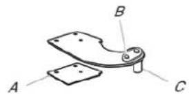
A. Plastic spacer
B. Hinge pin screw
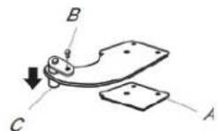
C. Hinge pin
■ Fasten the Top Hinge to the opposite side of the cabinet, inserting the screws only halfway, so you will be able to replace and align the freezer door later.
- Line up the doors so that the bottom of the freezer door aligns evenly with the top of the refrigerator door. Tighten all screws. NOTE: The distance between the doors should be approximately 5/8" (16 mm).
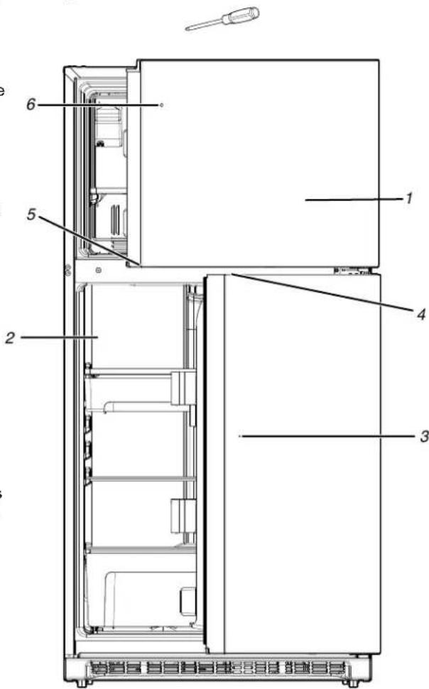
- Remove the film from the door.
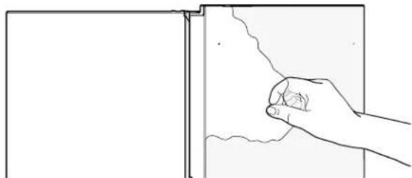
natural_image
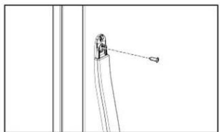
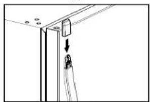
Line drawing of a hand holding a small object near a window frame (no text or symbols)- Find door handles and installation kit inside refrigerator.
NOTE: The kit could come in an vertical or horizontal way.
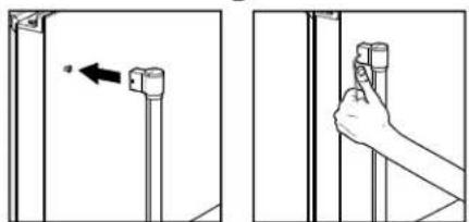
- Align handle, then tighten the screws and the set screw completely, plus an additional quarter-turn.
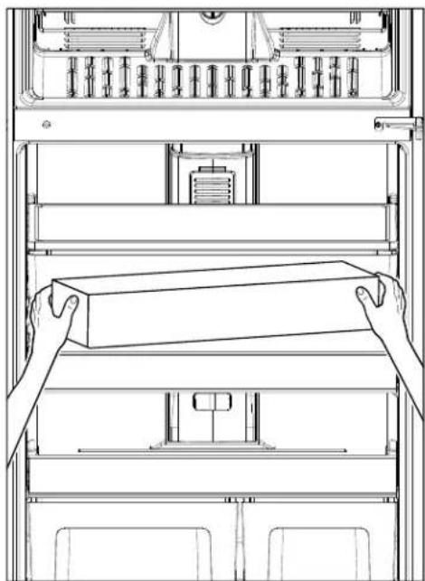
natural_image
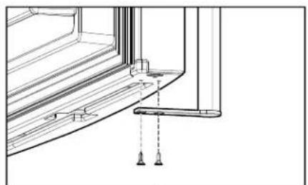
Line drawing of hands stacking a rectangular box on an open rack inside a server cabinet (no text or symbols)- Align one of the handles with the door screws, and push the base against the door. Partially tighten the screws and the set screw.
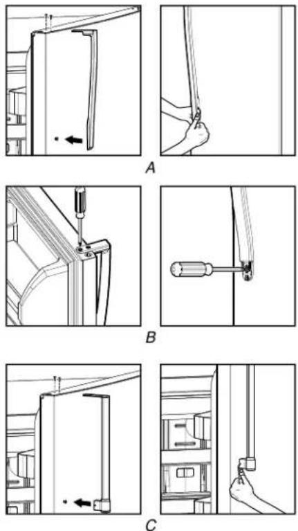
NOTE: For some models the type of handles change (A, B, C).

natural_image
Three technical line drawings of a mechanical assembly with labeled components (A, B, C), showing structural details without any text or symbols.- Align the second handle with the door screws and push the base firmly against the door. Partially tighten the screws (2 turns).
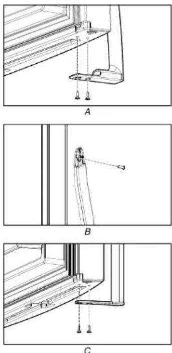
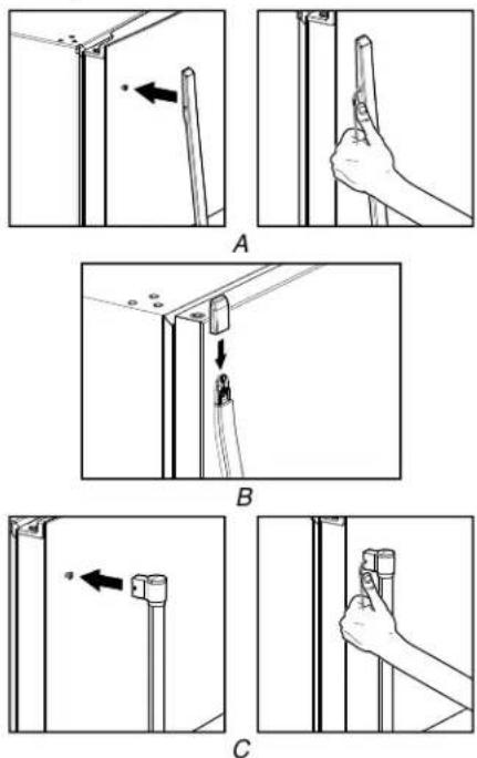
natural_image
Technical line drawings of three window frame structures labeled A, B, and C, showing structural details without any text or symbols.- Insert the set screw and partially tighten (2 turns). Align handle, then tighten the screws and set screw completely plus an additional quarter-turn.
Final Steps
WARNING
Electrical Shock Hazard
Plug into a grounded 3 prong outlet.
Do not remove ground prong.
Do not use an adapter.
Do not use an extension cord.
Failure to follow these instructions can result in death fire, or electrical shock.
- Check all holes to make sure that hole plugs and screws place. Install the top hinge cover again. See Top Hinge graphic.
- Remove the cover from the base grille. Move the cover to the opposite side.
- Align the clips on the base grille with the screws on the bot of the cabinet. Push the base grille toward the cabinet until flush.
- Plug into a grounded 3 prong outlet.
- Reset the controls. See "Operating Instructions".
- Return all removable door parts to doors and food to refrigerator.
Adjust the Doors
WARNING
Excessive Weight Hazard
Use two or more people to lift the appliance door.
Failure to do so can result in back or other injury.
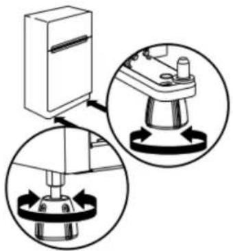
Your refrigerator has two adjustable levelers, one on each side, at the base of the refrigerator. If your refrigerator seems unsteady or if you want the doors to close more easily, adjust the level and tilt of the refrigerator.
- Turn the leveler to the left to raise that side of the refrigerator or to the right to lower that side. It may take several turns to adjust the tilt of the refrigerator.
NOTE: Having someone push against the top of the refrigerator takes some weight off the levelers. This makes it easier to turn the levelers.
- Open both doors again to make sure that they close as easily as you like. If not, tilt the refrigerator slightly more to the rear by turning both levelers to the right. It may take several more turns.
NOTE: To keep the refrigerator level, make the same adjustment to each side.
- Using a level, make sure the refrigerator is still level from side to side. Readjust if necessary.
natural_image
Diagram showing mechanical assembly with circular insets illustrating motion or force directions (no text or symbols)REFRIGERATOR AND FREEZER FEATURES
Refrigerator Shelves
Important information to know about glass shelves and covers:
Do not clean glass shelves or covers with warm water when they are cold. Shelves and covers may break if exposed to sudden temperature changes or impact, such as bumping. Tempered glass is designed to shatter into many small, pebble-size pieces.
This is normal. Glass shelves and covers are heavy. Use both hands when removing them to avoid dropping.
Refrigerator Shelves
The shelves in your refrigerator are adjustable to match your individual storage needs.
Storing similar food items together in your refrigerator and adjusting the shelves to fit different heights of items will make finding the exact item you want easier. It will also reduce the amount of time the refrigerator door is open, and save energy.
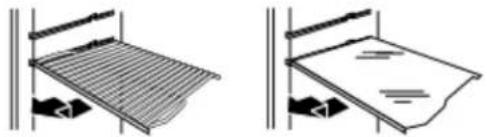
To remove and replace a shelf:
- Remove items from the shelf.
- Slide the shelf straight out to the stop.
- Depending on your model, lift back or front of the shelf past the stop. Slide shelf out the rest of the way.
- Replace the shelf by sliding the back of the shelf into the train in the wall of the cabinet.
- Guide the front of the shelf into the shelf track. Be sure to the shelf in all the way.
natural_image
Two technical diagrams showing a grid-patterned panel being lifted by a stand, with no visible text or symbols.Freezer Shelf
Important information to know about glass shelves and covers:
Do not clean glass shelves or covers with warm water when they are cold. Shelves and covers may break if exposed to sudden temperature changes or impact, such as bumping. Tempered glass is designed to shatter into many small, pebble-size pieces. This is normal. Glass shelves and covers are heavy. Use both hands when removing them to avoid dropping.
Full-Width Shelf (on some models)
Depending on your model, the shelf may be wire or glass.
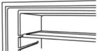
To remove and replace the freezer shelf:
- Remove items from the shelf.
- Lift back of shelf over stop and slide shelf straight out.
- Replace the shelf by sliding the back of the shelf into the tracks on walls of cabinet.
- Be sure to slide the shelf in all the way.
natural_image
Pure line drawing of a cabinet or shelf structure without any text, numbers, or symbolsHalf-Width Shelf (on some models)
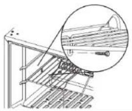
IMPORTANT: The half-width shelf can only be installed in the left-hand side of the freezer compartment.
- Remove items from the shelf.
- Remove the shelf screw. Lift back of the shelf over the stop and slide it out.
- Replace the shelf by sliding the back of the shelf into the tracks on the walls of the cabinet. Fasten the shelf screw.
natural_image
Technical line drawing of a mechanical assembly with a magnified inset showing a pin inserted into a component (no text or symbols present)Frozen Food Storage Guide
Storage times will vary according to the quality and type of food, the type of packaging or wrap used (should be airtight and moisture-proof), and the storage temperature. Seal the package or container securely to avoid taste and odor transfer throughout the product. Ice crystals inside a sealed package are normal. This is simply means that moisture in the food and air inside the package have condensed, creating ice crystals.
put no more unfrozen food into the freezer than will freeze within 24 hours (no more than 2 lbs to 3 lbs of food per cubic foot [907 g per L to 1,350 g per L] of freezer space). Leave enough space in the freezer for air to circulate around packages. The freezer door must close tightly.
NOTE: For more information on preparing food for freezing, check a freezer guide or reliable cookbook.
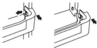
Door Rails or Trivets
SNAP ON DOOR RAILS OR TRIVETS
To remove and replace the rails or trivets:
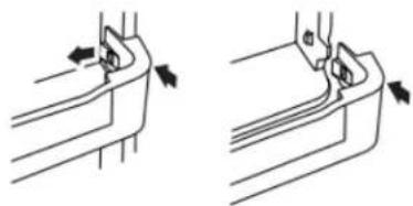
- Depending on your model, remove the rails or trivets by pushing in slightly on the front of the bracket while pulling out on the inside tab. Repeat these steps for the other end.
- Replace the rails or trivets by aligning the ends of the brackets with the buttons on the sides of the door liner. Firmly snap bracket and assembly onto the tabs above the shelf as shown.
Style 1 - Door Rails

natural_image
Technical line drawing of two mechanical components with directional arrows indicating movement (no text or symbols)Trivets
natural_image
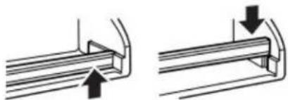
Two technical line drawings showing mechanical joint or bracket assembly with arrows indicating direction (no text or symbols)DROP-IN DOOR RAILS
To remove and replace the rails:
- Remove the rails by pulling straight up on each end of the rail.
- Replace the rails by sliding the shelf rail into the slots on the door.
natural_image
Pure mechanical diagram showing two pipe connection configurations without any text or symbolsCan Racks and Bins (on some models)
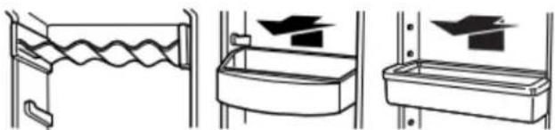
Can Racks and Door Bins
NOTE: Can racks may be purchased as an accessory for some models.
To remove and replace the racks/bins:
- Remove the rack/bin by lifting it and pulling it straight out.
- Replace the rack/bin by sliding it in above the desired support and pushing it down until it stops.
natural_image
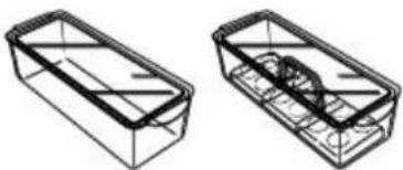
Three technical diagrams showing different mechanical or structural configurations (no text or symbols present)Egg or Utility Bins
Depending on your model, you may have a one, two, or three piece bin. Eggs may be stored in the egg tray or loose in the
NOTE: Store eggs in a covered container for long-term storage. your model does not have an egg storage bin, store eggs in the original container on an interior shelf.
natural_image
Two technical line drawings of rectangular containers with internal compartments (no text or symbols)Deli or Meat Drawer
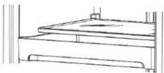
The deli drawer design allows flexible positioning. Deli or Meat Drawer
- Remove deli drawer.
- Release cover and place it between the desired crossbars.
- Secure the rear clips onto the shelf.
- Replace the drawer.
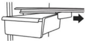
To remove and replace the drawer:
- Slide deli drawer out to the stop.
- Lift front of deli drawer with one hand while supporting bottom of drawer with other hand. Slide drawer out the rest of the way.
- Replace the drawer by sliding it back in fully past the drawer stop.
natural_image
Line drawing of a two-tiered shelf or platform structure (no text or symbols)DRAWER COVER
To remove and replace the drawer cover:
Style 1 - Wire Shelves
- Remove the deli drawer.
- Push the cover back to release the rear clips from the shelf. Tilt the cover up at the front, and then pull it forward.
-
Replace the deli drawer.
-
Replace the deli drawer cover by fitting the notches and clipsTo remove and replace the crisper cover: on the cover over the rear and center crossbars on the shelf. Remove the crisper(s).
Style 2 - Glass Shelves
- Remove the drawer.
- Remove items from the shelf.
- Slide the shelf straight out to the stop.
- Slide the cover to one side until free.
-
Insert the cover into the shelf tracks.
-
Slide the shelf back into the refrigerator, and then replace the deli drawer.
NOTE: On some models the drawer slides sideways on the shelf to allow for flexible positioning.
natural_image
Pure mechanical diagram showing a lever mechanism with an arrow indicating direction (no text or symbols)Meat Storage Guide
Store most meat in original wrapping as long as it is airtight and moisture-proof. Rewrap if necessary. See the following chart for storage times. When storing meat longer than the times given, freeze the meat.
fresh fish or shellfish .... use same day as purchased
Chicken, ground beef, variety meats (liver) 1-2 days
Cold cuts, steaks/roasts 3-5 days
Cured meats 7-10 days
Leftovers - Cover leftovers with plastic wrap, aluminum foil, or plastic containers with tight lids.
Crisper
Crisper Cover
Style 1 - Plastic Cover
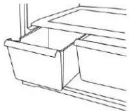
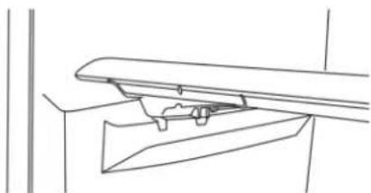
To remove and replace the crisper cover:
- Remove the crisper(s).
natural_image
Line drawing of a mechanical component with no text or symbols- Lift the cover up and slide it out.
- Replace the cover by fitting the cover tabs into the lowest cabinet slots and pushing them in. Lower the front retainers into place.
natural_image
Pure technical line drawing of a mechanical assembly without any text, numbers, or symbolsStyle 2 - Glass Cover
To remove and replace the crisper cover: f1. Remove the crisper(s).
-
Pull the glass straight out.
-
Replace the glass by pushing it straight in.
natural_image
Architectural line drawing of a two-story building facade with windows and doorways (no text or symbols)Crisper Humidity Control (On Some Models)
You can control the amount of humidity in the moisture-sealed crisper. Adjust the control to any setting between Low and High.
Low (open) – lets moist air out of the crisper for best storage of fruits and vegetables with skins.
■ Fruit: Wash, let dry, and store in refrigerator in plastic bag or crisper. Do not wash or hull berries until they are ready to use Sort and keep berries in original container in crisper or store in a loosely closed paper bag on a refrigerator shelf.
■ Vegetables with skins: Place in plastic bag or plastic container and store in crisper.
High (closed) – keeps moist air in the crisper for best storage of fresh, leafy vegetables.
■ Leafy vegetables: Wash in cold water, drain, and trim or tear off bruised and discolored areas. Place in plastic bag or plas container and store in crisper.
Ice Maker
For models with a water filter, after connecting the refrigerator to a water source or replacing the water filter, fill and discard three full containers of ice to prepare the water filter for use.
For products without any parts of the ice dispensing circuit, ice maker and internal water circuit parts must be installed by the manufacturer or by its qualified service technician.
For Easy Connect (ice maker ready) products, ice maker can be easily installed by the user, following instructions given with the kit.
In order to know which type of ice maker fits in your product, please refer to the serial tag inside the food compartment of appliance for ice maker kit model information.
Refer to the Quick Start Guide for contact information.
Turning the Ice Maker On/Off
To turn the ice maker On, simply lower the wire shutoff arm or in if your ice maker has a rocker switch, move the ON/OFF rocker switch to the ON (I) position.
■ To manually turn the ice maker off, lift the wire shutoff arm to the off (arm up) position and listen for the click. For the ice maker with a rocker switch move the ON/OFF rocker switch to the OFF (O) position.
NOTE: Your ice maker has an automatic shutoff. As ice is made, the ice cubes will fill the ice storage bin and the ice cubes will raise the wire shutoff arm to the off (arm up) position. Do not force the wire arm up or down.
Utility Compartment
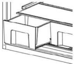
The utility compartment may be removed for easier cleaning.
To remove and replace the utility compartment:
- Remove the utility compartment by squeezing against one side while raising the utility compartment up and pulling it straight out.
- Replace the utility compartment by positioning one side in the lock and sliding in the opposite side until it stops.
natural_image
Technical line drawing of a mechanical component with a magnified inset showing internal detail (no text or symbols)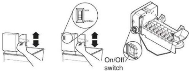
Ice Storage Bin
NOTE: Turn off the ice maker before removing the ice storage bin to serve ice or to clean the bin. This will keep the ice cubes from dropping out of the ice maker and into the freezer compartment. After replacing the ice storage bin, turn on the ice maker.
- Wash the ice storage bin with mild soap and warm water.
- Slide the ice storage bin under the ice maker and push it toward the back as far as it will go.
- Lower the arm on the ice maker to the On position.
Ice Production Rate
■ The ice maker should produce a complete batch of ice approximately every 3 hours, approximately 8 to 12 batches of ice in a 24 hour period.
■ To increase ice production, lower the freezer and refrigerator temperature. See "Using the Controls". Wait 24 hours between adjustments.
■ Maximum ice production (on some models): If your refrigerator has the maximum ice production feature, push the switch to Max to produce approximately 16 to 20 batches of ice in a 24 hour period.
Remember:
NOTE: The dispenser will automatically turn off Measured Fill after 1 minute of inactivity. When Measured Fill is turned off, any changes you have made will be lost and all defaults will be restored.
Operating Instructions
WARNING: To reduce the risk of fire, electric shock, or injury to persons, read the IMPORTANT SAFETY INSTRUCTIONS, before operating this appliance.
NOTE: Before operating this appliance, make sure it has been properly installed.
Your refrigerator has two controls that affect the temperature. The Temperature control is located at the top front of the refrigerator compartment and the Airflow control is located on the back wall of the freezer compartment.
Temperature Control
For convenience, the temperature control is preset at the factory. When you first install your refrigerator, make sure the control is still preset as shown below.
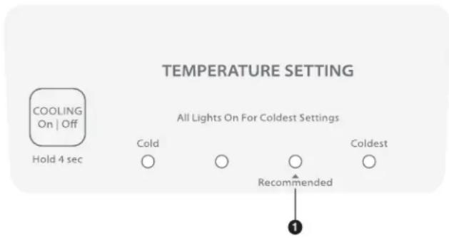
- Preset Temperature Control
IMPORTANT:
■ The recommended setting should be correct for normal household refrigerator use. The controls are set correctly when milk or juice is as cold as you like and when ice cream is first
■ Wait 24 hours for your refrigerator to cool completely before adding food. If you add food before the refrigerator has cooled completely, your food may spoil.
NOTE: Adjusting the refrigerator and freezer controls to a colder than recommended setting will not cool the compartments any faster.
If the temperature is too warm or too cold in the refrigerator of freezer, first check the air vents to be sure they are not block before adjusting the controls.
Adjusting the Temperature Control
NOTE: Except when starting the refrigerator, do not adjust the control more than one setting at a time. Wait 24 hours between adjustments for the temperature to stabilize.
■ If you need to adjust the temperature in either the refrigerator or freezer compartment, use the settings listed in the chart below as a guide.
NOTE: Adjusting the refrigerator and freezer controls to a colder than recommended setting will not cool the compartments any faster.
If the temperature is too warm or too cold in the refrigerator, freezer, first check the air vents to be sure they are not bloc before adjusting the controls.
In some models
■ Press the Temp Setting button to toggle among the four LED lights which indicate the temperature setting. Reading from left to right, the LED in the first position is the least cold. The LEDs indicate increasingly colder settings as you continue to the right until all four LEDs are illuminated.
NOTE: For the first to fourth setting, only one LED of the four LEDs will be lit. All four LEDs will be lit when you have reached the coldest setting.
| CONDITION/REASON CONDITION/REASON | |
| Refrigerator too warm Temp | control one setting higher |
| Refrigerator too cold Temp | control one setting lower |
| Freezer too warm/too little ice* | Airflow or Temp control one setting higher |
| Freezer too cold Airflow or T | Temp control one setting lower |
| CONDITION/REASON CONDITION/REASON | |
| Refrigerator too warm Temp | control one setting higher |
| Refrigerator too cold Temp | control one setting lower |
| Freezer too warm/too little ice* | Airflow or Temp control one setting higher |
| Freezer too cold Airflow or T | Temp control one setting lower |
*Ice makers and Ice maker kits are available on select models.
Cooling ON/OFF
■ To turn cooling off, press and hold the Setting button for 4 seconds until all lights stay on for 1 second. To turn cooling back on, press and hold the Setting button again for 4 seconds.
NOTE: Neither compartment will cool when the control is set to Off.
Airflow Control
The Airflow control regulates the amount of air flowing between the freezer and the refrigerator compartments. Changing the
Airflow setting to Min removes cool air from the freezer and uses it to cool the refrigerator.
When you plug in the refrigerator for the first time, turn the Airflow control to the Recommended setting.
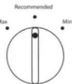
Adjusting The Airflow Control
If you want to temporarily increase the cold airflow to a specific compartment, adjust the control:
■ Max - Increase airflow to the freezer
■ Min - Increase airflow to the refrigerator
IMPORTANT: Once the performance is achieved, return the Airflow control to the recommended setting to keep the refrigerator operating at optimum efficiency.
| CONDITION/REASON ADJUSTMENT | |
| Heavy ice use* Max | |
| Hot room temperature Max –ked | to maintain ice making production rate |
| Large quantity of groceries Min – to quickly chill food and beverages | |
*Ice makers and ice maker kits are available on select models.
SÉCURITÉ DU RÉFRIGÉRATEUR
natural_image
Line drawing of a refrigerator with open doors and shelves (no text or symbols)ENTRETIEN ET RÉPARATION Nettoyage
AVERTISSEMENT
Risque d'explosion
natural_image
Technical line drawing of a mechanical component or housing (no text or symbols)natural_image
Technical diagram showing a mechanical assembly with an inset close-up of a component (no text or symbols visible)natural_image
Diagram of a hand holding a tool with an arrow indicating rotation (no text or symbols present)natural_image
Diagram of a bowl with curved layers and directional arrows indicating flow or movement (no text or symbols)INSTRUCTIONSD'INSTALLATION
natural_image
Illustration of a rectangular electronic component with grid-like internal structure (no text or symbols)5/16" Hex-Head Top Hinge Screw
natural_image
Technical line drawing of a mechanical assembly with no visible text or symbolsnatural_image
Simple diagram showing a container with an arrow and two circles inside, no text or symbols present.natural_image
Simple line drawing of a container with an arrow and two circles inside, no text or symbols present.natural_image
Mechanical assembly diagrams showing two configurations with labeled components A, B, and C (no text or symbols beyond labels)natural_image
Line drawing of a hand holding a small object near a wall, no text or symbols presentnatural_image
Line drawing of a server rack with two hands installing a rectangular box (no text or symbols)natural_image
Technical line drawing of a mechanical bracket or mounting bracket with two vertical fasteners inserted (no text or symbols)A
natural_image
Pure technical line drawing of a mechanical component without any text, numbers, or symbolsB
natural_image
Technical line drawing of a window frame with mounting bracket and vertical guide rail (no text or symbols)C
natural_image
Two-step diagram showing a hand holding a tool near a vertical panel, with an arrow indicating direction (no text or symbols present)A
natural_image
Pure technical diagram of a mechanical assembly with no text, numbers, or symbolsB
natural_image
Two-step diagram showing a hand holding a small object next to a vertical rod, with an arrow indicating direction (no text or symbols present)C
Étapes finales
AVERTISSEMENT

natural_image
Diagram showing mechanical assembly with circular insets illustrating rotational components (no text or symbols)CARACTÉRISTIQUES DU RÉFRIGÉRATEUR ET DU CONGÉLATEUR
natural_image
Two technical diagrams showing a grid-patterned panel being tilted, with no visible text or symbols.natural_image
Pure line drawing of a structural frame with no text, numbers, or symbolsnatural_image
Technical line drawing of a mechanical assembly with a magnified inset showing a screw inserted into a spring (no text or symbols)natural_image
Technical line drawing showing two mechanical assembly steps with arrows indicating motion direction (no text or symbols)Balconnets
natural_image
Two technical line drawings showing a mechanical component with arrows indicating motion or force direction (no text or symbols)TRINGLES DÉPOSÉES DANS LA PORTE
natural_image
Pure mechanical diagram showing two sequential steps of a pipe connection (no text or symbols)natural_image
Three technical diagrams showing different mechanical or structural configurations (no text or symbols present)natural_image
Two wireframe diagrams of rectangular containers with internal compartments and a central circular feature (no text or symbols)natural_image
Line drawing of a staircase with shelves and legs (no text or symbols)COUVERCLE DE TIROIR
natural_image
Pure technical diagram of a mechanical assembly with no text or symbolsnatural_image
Line drawing of a mechanical component with no visible text or symbolsnatural_image
Pure technical line drawing of a mechanical assembly without any text, numbers, or symbolsnatural_image
Architectural line drawing of a two-story building facade with windows and doorways (no text or symbols)natural_image
Technical line drawing of a mechanical component with a magnified inset showing internal detail (no text or symbols)Machine à glaçons

- Your safety and the safety of others are very important.
- DANGER
- WARNING
- IMPORTANT SAFETY INSTRUCTIONS
- SAVE THESE INSTRUCTIONS
- Proper Disposal of Your Old Refrigerator
- MAINTENANCE AND CARE
- Cleaning
- IMPORTANT:
- To Clean Your Refrigerator:
- NOTE:
- Changing the Light Bulbs
- CHANGING THE LIGHT BULB
- To Remove and Replace Light Bulb:
- FREEZERLIGHT
- Vacations
- IfYouChoosetoLeavetheRefrigeratorOnWhileYou're Away:
- IfYouChoosetoTurnOfftheRefrigeratorBeforeYouLeave:
- Moving
- INSTALLATIONINSTRUCTIONS
- UnpacktheRefrigerator
- ExcessiveWeightHazard
- RemovethePackaging
- When Moving Your Refrigerator:
- CleanBeforeUsing
- Importantinformationtoknowaboutglassshelvesand covers:
- Location Requirements
- Electrical Requirements
- Recommended Grounding Method
- Water Supply Requirements
- Water Pressure
- Reverse Osmosis Water Supply
- Connect the Water Supply
- Connect to Water Line
- Connect to Refrigerator
- Style 1
- Style 2
- Complete the Installation
- Electrical Shock Hazard
- Installing the Air Filter
- Air Filter Status Indicator
- On models with notches:
- On models without notches:
- Replacing the Air Filter
- REFRIGERATOR DOORS
- Door and Handle Instructions
- Remove Doors and Hinges
- 5/16" Hex-Head Top Hinge Screw
- Reverse Doors and Hinges (optional) _3 .
- Style 1 - Standard Door Models
- Cabinet
- Freezer Door
- NOTES:
- Refrigerator Door
- Style 2 - Contour Door Models
- Replace Doors and Hinges
- Install Doors Handles
- Final Steps
- Adjust the Doors
- REFRIGERATOR AND FREEZER FEATURES
- Refrigerator Shelves
- To remove and replace a shelf:
- Freezer Shelf
- Full-Width Shelf (on some models)
- Half-Width Shelf (on some models)
- Frozen Food Storage Guide
- Door Rails or Trivets
- SNAP ON DOOR RAILS OR TRIVETS
- DROP-IN DOOR RAILS
- Can Racks and Bins (on some models)
- Can Racks and Door Bins
- Egg or Utility Bins
- Deli or Meat Drawer
- DRAWER COVER
- To remove and replace the drawer cover:
- Style 1 - Wire Shelves
- Style 2 - Glass Shelves
- Meat Storage Guide
- Crisper
- Crisper Cover
- Style 1 - Plastic Cover
- Style 2 - Glass Cover
- Crisper Humidity Control (On Some Models)
- Ice Maker
- Turning the Ice Maker On/Off
- Utility Compartment
- To remove and replace the utility compartment:
- Ice Storage Bin
- Ice Production Rate
- Remember:
- Operating Instructions
- Temperature Control
- Adjusting the Temperature Control
- In some models
- Cooling ON/OFF
- Airflow Control
- Adjusting The Airflow Control
- SÉCURITÉ DU RÉFRIGÉRATEUR
- ENTRETIEN ET RÉPARATION Nettoyage
- AVERTISSEMENT
- INSTRUCTIONSD'INSTALLATION
- Étapes finales
- CARACTÉRISTIQUES DU RÉFRIGÉRATEUR ET DU CONGÉLATEUR
- Balconnets
- TRINGLES DÉPOSÉES DANS LA PORTE
- COUVERCLE DE TIROIR
- Machine à glaçons
Brand : Crosley
Model : CRTW2154SB
Category : Fridge