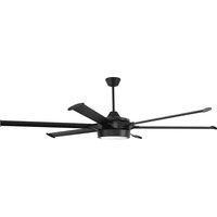
PRT78 - Fan Craftmade - Free user manual and instructions
Find the device manual for free PRT78 Craftmade in PDF.


| Product Type | Ceiling fan with LED lighting kit |
| Brand | Craftmade |
| Model | PRT78 (also compatible with PRT102 and PRT120) |
| Net weight | 18 kg (39.68 lb) |
| Approximate diameter | 198 cm (78 inches) |
| Motor | DC motor |
| Number of speeds | 6 speeds |
| Lighting | Integrated LED lighting kit, dimmable (compatible dimmer) |
| Power supply | 120 V, 60 Hz (US standard) |
| Blade material | Composite wood (estimated) |
| Number of blades | 6 |
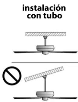
| Installation | Flat ceiling only, with downrod (not flush mount, not sloped) |
| Control | Wired wall control + wireless handheld remote (12V battery included) |
| Connectivity | Wi-Fi via Bond Home app (voice control and scheduling) |
| Warranty | Limited lifetime warranty with conditions (1 year repair/replacement, 5 years motor, 6 years to life labor) |
| Use | Approved for damp locations (covered patio, bathroom with sufficient ceiling height) |
| Safety | Safety cable mandatory; automatic shutdown in case of wind gust (60s beep then restart) |
| Maintenance | Dry or slightly damp cloth; do not use water or detergent |
| Spare parts | Available from customer service (1-800-486-4892) or on craftmade.com |
| Repairability | Motor repairable/replaceable; LED not user serviceable (call customer service) |
Frequently Asked Questions - PRT78 Craftmade
User questions about PRT78 Craftmade
0 question about this device. Answer the ones you know or ask your own.
Ask a new question about this device
Download the instructions for your Fan in PDF format for free! Find your manual PRT78 - Craftmade and take your electronic device back in hand. On this page are published all the documents necessary for the use of your device. PRT78 by Craftmade.
USER MANUAL PRT78 Craftmade
READ THESE INSTRUCTIONS AND SAVE THEM FOR FUTURE USE
natural_image
Silhouette of a black-and-white overhead fan with five blades and a central hub (no text or symbols)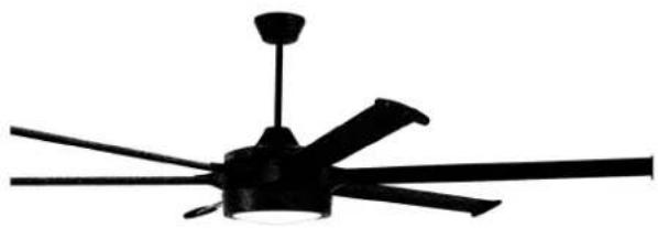
natural_image
Black overhead fan with five blades and a top hub (no text or symbols)Prost
Installation Guide
For Models:
PRT78
PRT102
PRT120
WARNING:
DUE TO THE SIZE AND
WEIGHT OF THE FAN, READ
ALL SAFETY TIPS CAREFULLY
BEFORE INSTALLING FAN.
WARNING:
DC Motor will not operate until blades are installed

APPROVED FOR USE
IN DAMP LOCATIONS
net weight of fan: 39.68 lb (18 kg), PRT78
41.89 lb (19 kg), PRT102
44.09 lb (20 kg), PRT120
Table of Contents:
Safety Tips. pg. 3
Unpacking Your Fan. pg. 4
Parts Inventory. pg. 4
Installation Preparation. pg. 5
Mounting Plate & Hanging
Bracket Installation. pgs. 5 - 6
Fan Assembly. pgs. 6 - 8
Wiring. pgs. 8 - 9
Canopy Assembly. pg. 9
Blade Assembly. pg. 10
Light Kit Assembly. pg. 11
Handheld Remote Control
Assembly. pg. 12
Automated Learning Process./
Activating Code. pg. 13
Remote/Wall Control Operation. pg. 13
Smart Ceiling Fan Wi-Fi Control. pg. 14
Testing Your Fan. pg. 15
Troubleshooting. pg. 16
Warranty. pg. 16
Parts Replacement. pg. 16
Activating Your New Smart Fan; Downloading the Bond Home App
- Using your smart device, navigate to the application store (Apple App store or Google Play), download the free Bond Home app and create account.
- Ensure the fan and receiver are receiving power from the house supply using the remote control to turn the fan and light ON and OFF.
- Open the Bond Home App on your smart device and follow step-by-step instructions included in the app to add your fan.
- Enjoy fan features and functionality that you can only get from activating the fan through the app.
SAFETY TIPS.
WARNING: To reduce the risk of electrical shock, turn off the electricity to the fan at the main fuse box or circuit panel before you begin the fan installation or before servicing the fan or installing accessories.
1. READ ALL INSTRUCTIONS AND SAFETY INFORMATION CAREFULLY BEFORE INSTALLING YOUR FAN AND SAVE THESE INSTRUCTIONS.
CAUTION: To avoid personal injury, the use of gloves may be necessary while handling fan parts with sharp edges.
- Make sure all electrical connections comply with Local Codes or Ordinances, the National Electrical Code, and ANSI/NFPA 70-1999. If you are unfamiliar with electrical wiring or if the house/building wires are different colors than those referred to in the instructions, please use a qualified electrician.
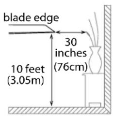
- Make sure you have a location selected for your fan that allows clear space for the blades to rotate, and at least ten (10) feet (3.05 meters) of clearance between the floor and the fan blade tips. (At least seven (7) feet (2.13 meters) of clearance between the floor and the fan blade tips are needed for PRT78 ONLY). The fan should be mounted so that the tips of the blades are at least thirty (30) inches (76 centimeters) from walls or other upright structures.
- The outlet box and ceiling support joist used must be securely mounted, and capable of supporting at least 50 pounds (22.68 kilograms). The box must be supported directly by the building structure. Use only CUL (Canada) or UL (USA) listed outlet boxes marked "FOR FAN SUPPORT."
WARNING: To reduce the risk of fire, electrical shock, or personal injury, mount to the outlet box marked "Acceptable for Fan Support of 22.68 kg (50 lb) or less," and use the mounting screws provided with the outlet box as well as the two bolt screws and washers included with the fan. Most outlet boxes commonly used for the support of lighting fixtures are not acceptable for fan support and may need to be replaced. Consult a qualified electrician if in doubt.
WARNING: To reduce the risk of fire, electrical shock, or personal injury, wire connectors provided with this fan are designed to accept only one 12 gauge house wire and two lead wires from the fan. If your house wire is larger than 12 gauge or there is more than one house wire to connect to the corresponding fan lead wires, consult an electrician for the proper size wire connectors to use.
- Electrical diagrams are for reference only.
- After installation is complete, check that all connections are absolutely secure.
- After making electrical connections, spliced conductors should be turned upward and pushed carefully up into the outlet box. The wires should be spread apart with the grounded conductor and the equipment-grounding conductor on opposite sides of the outlet box.
WARNING: To reduce the risk of serious bodily injury, DO NOT use power tools to assemble any part of the fan, including the blades.
WARNING: To reduce the risk of fire or electrical shock, do not use this fan with any solid state speed control device or control fan speed with a full range dimmer switch. [Using a full range dimmer switch to control fan speed will cause a loud humming noise from fan.]
- Do not operate the reverse switch until fan has come to a complete stop. [Note: If using remote control with reverse capability, reverse fan blade direction only when on LOW speed.]
- Do not insert anything between the fan blades while they are rotating.
- When operating the fan in a covered patio location, it is possible for high wind gusts to cause the fan to stop briefly. It will then emit a warning beep for 60 seconds and restart at the same setting. If you wish to restart the fan sooner, you may push the SPEED button during the 60-second warning beep.
WARNING: To reduce the risk of personal injury, do not bend the blade arms during assembly or after installation. Do not insert objects into the path of the blades.
WARNING: To avoid personal injury or damage to the fan and other items, be cautious when working around or cleaning the fan.
- Do not use water or detergents when cleaning the fan or fan blades. A dry dust cloth or lightly dampened cloth will be suitable for most cleaning.
WARNING: To reduce the risk of personal injury, use only parts provided with this fan. The use of parts OTHER than those provided with this fan will void the warranty.
WARNING: This fan MUST be installed with the safety cable provided with the fan. Failure to use the safety cable provided may result in personal injury, damage to the fan or damage to other property.
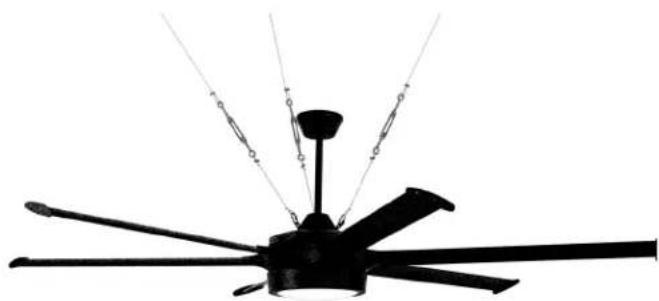
WARNING: Support cables MUST be used if installing fan in a covered patio. Failure to use the support cables provided may result in personal injury, damage to the fan or damage to other property.
CAUTION: Metal cover for use without light kit will be HOT if light is left on. To reduce the risk of personal injury, light kit must be OFF. Do NOT connect molex connections if installing metal cover.
CAUTION: Do NOT tamper with or attempt to repair LED component of fixture. The light source is designed for this specific application and should not be serviced by untrained personnel. If any servicing is required, call our customer service department.
- Light kit is dimmable to 10% with select dimmers.
Modifications not approved by the party responsible for compliance could void the user's authority to operate the equipment. [The equipment refers to the remote and/or wall control and/or LED light kit.]
NOTE: This equipment has been tested and found to comply with the limits for a Class B digital device, pursuant to Part 15 of the FCC Rules. These limits are designed to provide reasonable protection against harmful interference in a residential installation. This equipment generates, uses and can radiate radio frequency energy and, if not installed and used in accordance with the instructions, may cause harmful interference to radio communications. However, there is no guarantee that interference will not occur in a particular installation. If this equipment does cause harmful interference to radio or television reception, which can be determined by turning the equipment off and on, the user is encouraged to try to correct the interference by one or more of the following measures:
* Reorient or relocate the receiving antenna.
* Increase the separation between the equipment and receiver.
* Connect the equipment into an outlet on a circuit different from that to which the receiver is connected.
* Consult the dealer or an experienced radio/TV technician for help.
The LED light kit complies with Part 15 of the FCC Rules. Operation is subject to the following two conditions: (1) this LED light kit may not cause harmful interference, (2) this LED light kit must accept any interference received, including interference that may cause undesired operation.
Distributed by: Craftmade, 3901 South 20th Avenue, DFW Airport, TX, 75261; 1-800-486-4892
NOTE: The important safety precautions and instructions appearing in the manual are not meant to cover all possible conditions and situations that may occur. It must be understood that common sense and caution are necessary factors in the installation and operation of this fan.
1. Unpacking Your Fan.
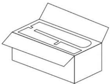
Carefully open the packaging. Remove items from Styrofoam inserts. Remove motor housing and place on carpet or Styrofoam to avoid damage to finish. Do not discard fan carton or Styrofoam inserts should this fan need to be returned for repairs. Check against parts inventory that all parts have been included.
natural_image
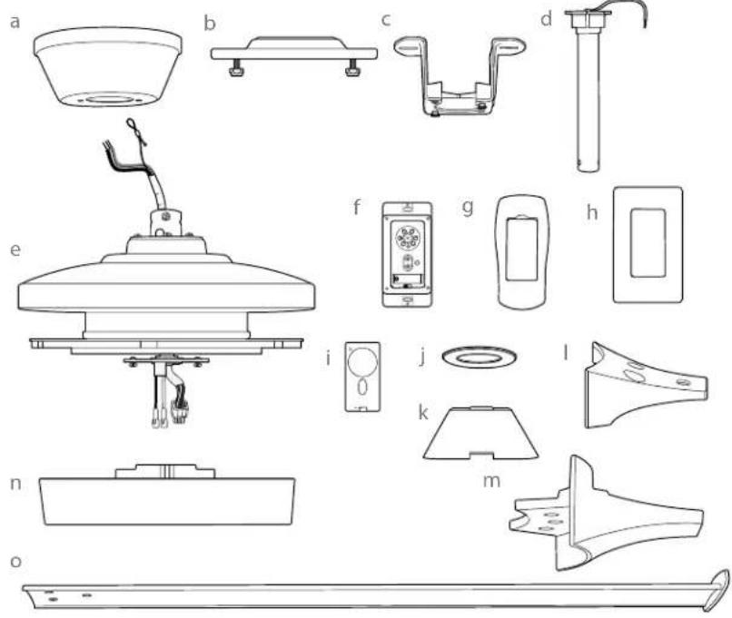
Line drawing of a closed box with an open lid and internal slot (no text or symbols)2. Parts Inventory.
a. canopy. 1 piece
b. mounting plate. 1 piece
c. hanging bracket. 1 piece
d. downrod. 1 piece
e. motor housing. 1 piece
f. wall control. 2 pieces
g. remote control cover. 1 piece
h. plate. 1 piece
i. faceplate. 3 pieces
j. canopy cover. 1 piece
k. yoke cover. 1 piece
I. blade arm. 6 pieces
m. blade plate. 6 pieces
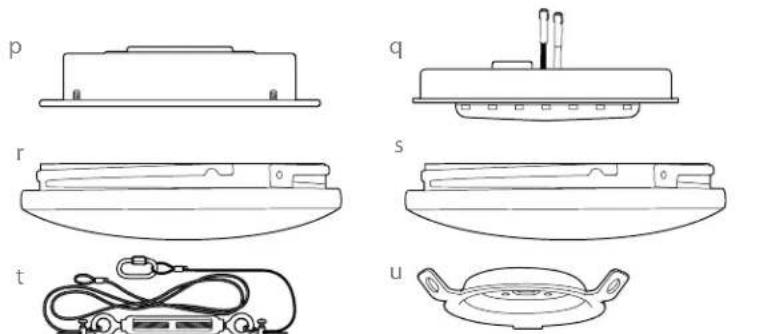
t. support cable. 3 pieces
u. support cable anchor. 1 piece
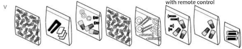
v. hardware packs

IMPORTANT REMINDER: You must
use the parts provided with this fan for proper installation and safety.

3. Installation Preparation.
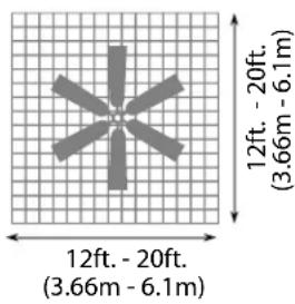
To prevent personal injury and damage, ensure that the hanging location allows the blades a clearance of 10 feet (3.05m) from the floor and 30in. (76cm) from any wall or obstruction. (At least seven (7) feet (2.13 meters) of clearance between the floor and the fan blade tips are needed for PRT78 ONLY). This fan is suitable for room sizes up to 400 square feet (37.2 square meters).
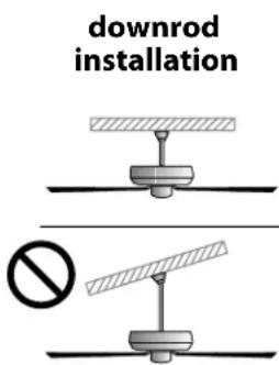
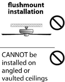
This fan can be mounted with a downrod on a regular (no slope) ceiling only. Fan cannot be mounted as a flushmount nor on a vaulted ceiling.
Installation requires these tools:
Phillips screwdriver, flat-head screwdriver, adjustable pliers or wrench, stepladder, wire cutters, and rated electrical tape.
4. Mounting Plate & Hanging Bracket Installation.
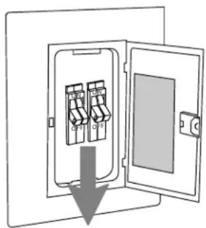
Turn off circuit breakers to current fixture from breaker panel and be sure operating light switch is turned to the OFF position.
WARNING: Failure to disconnect power supply prior to installation may result in serious injury.
Remove existing fixture.
WARNING: When using an existing outlet box, be sure the outlet box is securely attached to the building structure and can support the full weight of the fan. Ensure outlet box is clearly marked "Suitable for Fan Support of 22.68 kg (50lb) or less" and use mounting screws provided with the outlet box as well as the two bolt screws and washers included with the fan. If not, it must be replaced with an approved outlet box. Failure to do so can result in serious injury.
CAUTION: Be sure outlet box is grounded properly and that a ground wire (GREEN or bare) is present.
NOTE: Make sure outlet box screws and spring washers are removed from existing outlet box before installing mounting plate.
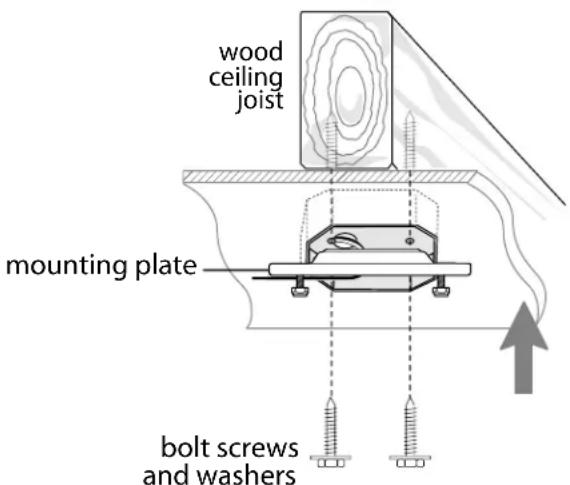
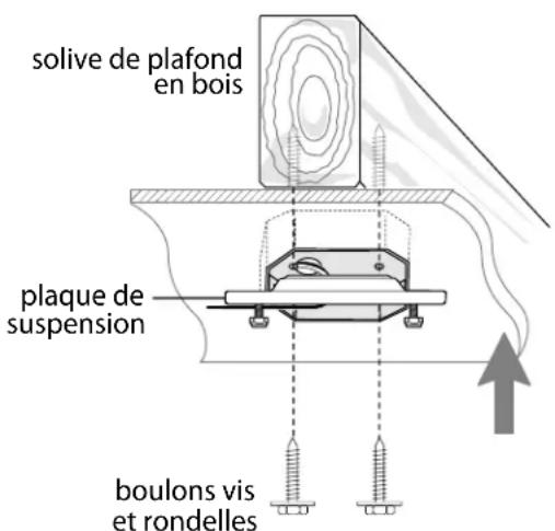
Attach mounting plate to wood ceiling joist with large bolt screws and washers (included in a hardware pack) by aligning holes on mounting plate to holes inside outlet box. Pull electrical wiring from outlet box through center hole in the mounting plate.
["Mounting Plate and Hanging Bracket Assembly" continued on next page.]
4. Mounting Plate & Hanging Bracket Installation. (cont.)
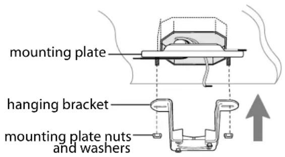
Remove preassembled nuts and washers from mounting plate. Attach hanging bracket to mounting plate by replacing nuts and washers on mounting plate. Arrange electrical wiring around the back of the hanging bracket and away from the hanging bracket opening.
WARNING: If outlet box is not supported by a wood ceiling joist, YOU MUST MAKE SURE outlet box is able to support the weight of the fan.
5. Fan Assembly.
Loosen yoke set screws and nuts at top of motor housing. Remove pin and clip from motor housing yoke. [Refer to diagram 1.]
Tip: To prepare for threading electrical wires through downrod, apply a small piece of electrical tape to the ends of the electrical wires--this will keep the wires together when threading them through the downrod. [Refer to diagram 1.]
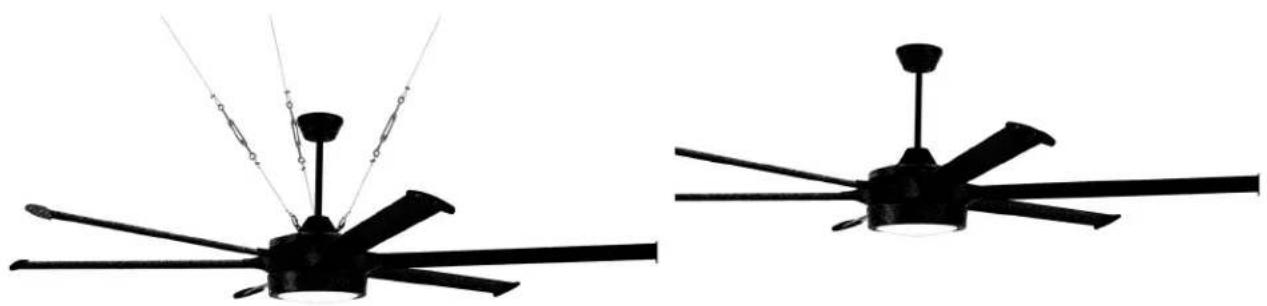
If you wish to install fan in a covered patio, remove 6 screws and washers from yoke plate at top of motor housing and set aside. Align holes in support cable anchor with holes in yoke plate and re-insert screws that were previously removed. Tighten all screws securely. [Refer to diagram 2.]
Remove 2 set screws from the top of downrod and save for later use. Slide downrod into canopy, canopy cover and yoke cover. [Refer to diagram 3.] (Note: Canopy cover must be turned with smooth side toward the motor housing.) If using support cable anchor, align openings on bottom of yoke cover with anchor holes on support cable anchor.
["Fan Assembly" continued on next page.]
NOTE: The important safety precautions and instructions appearing in the manual are not meant to cover all possible conditions and situations that may occur. It must be understood that common sense and caution are necessary factors in the installation and operation of this fan.
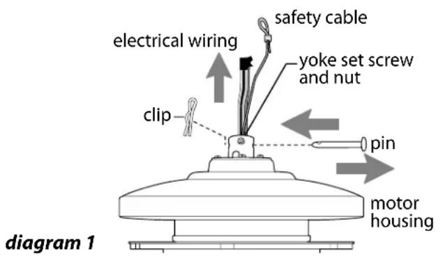
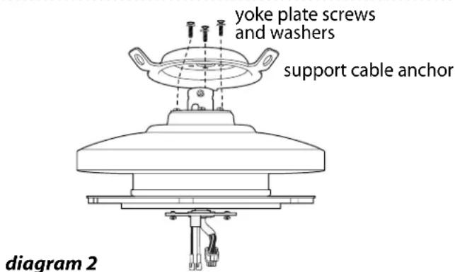
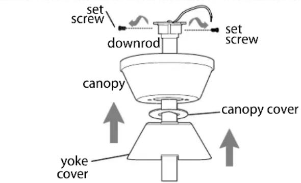
diagram 3
5. Fan Assembly. (cont.)
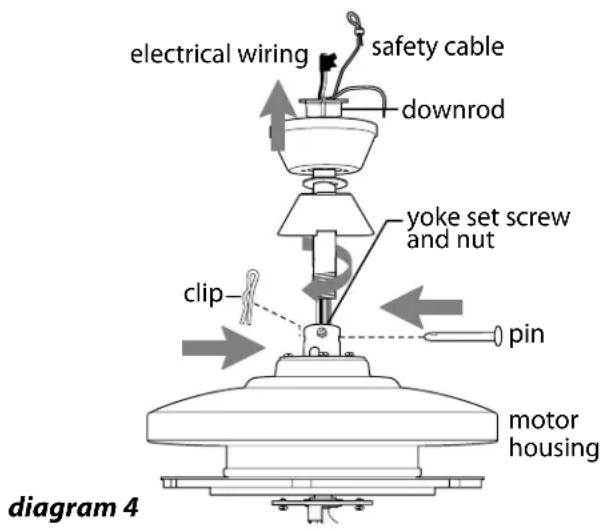
Thread safety cable and electrical wires through threaded end of downrod and pull extra wire slack from the upper end of the downrod.
[Refer to diagram 4.]
Thread downrod into the motor housing yoke until holes for pin and clip in downrod align with holes in yoke--make sure wires do not get twisted. Re-insert pin and clip that were previously removed. Tighten yoke set screws and nuts securely. [Refer to diagram 4.]
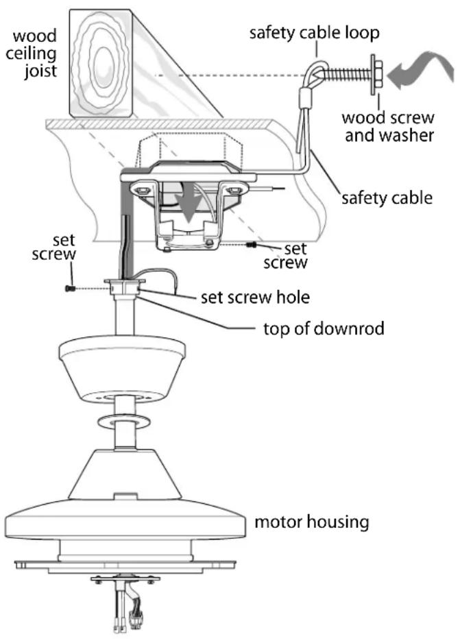
With the hanging bracket secured to the outlet box and able to support the fan, you are now ready to hang your fan. Grab the fan firmly with two hands. Slide downrod through opening in hanging bracket and then turn downrod so that the straight edges of the top of downrod align with the sides of the hanging bracket and the set crew holes align with the hanging bracket set crew holes. Pull down firmly on the downrod until it sits securely inside the hanging bracket. Attach hanging bracket to the top of downrod by inserting set screws previously removed into set screw holes on hanging bracket. Tighten both screws securely.
IMPORTANT: Due to the size (weight) of this fan, it is advisable to seek the help of another person to hold the stepladder in place and to then help lift the fan up to you once you are set on the ladder.
WARNING: Failure to align straight edges of the top of downrod with sides of hanging bracket may result in serious injury or death.
Find a secure attachment point (wood ceiling joist highly recommended) and secure safety cable. It will be necessary to use a heavy duty wood screw, washer and lock washer (not supplied) with the safety cable loop. If necessary, adjust the loop at the end of the safety cable. The loop at the end of the safety cable should just fit over the threads on the wood screw. Test safety cable by pulling on loose end of safety cable with pliers. If the safety cable slips, the loop must be adjusted smaller. Extra cable slack can be left in ceiling area.
["Fan Assembly" continued on next page.]
5. Fan Assembly. (cont.)
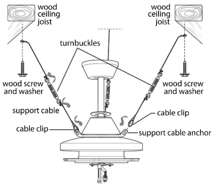
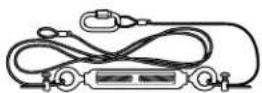
If you wish to install fan in a covered patio, secure clip on one support cable to one opening of support cable anchor. Repeat for remaining support cables.
Find a secure attachment point (wood ceiling joist highly recommended) and secure support cable. It will be necessary to use a heavy duty wood screw, washer and lock washer (included in hardware pack) with the support cable loop. If necessary, adjust screws on the cable turnbuckles to shorten/lengthen the cable slack. The loop at the end of the support cable should just fit over the threads on the wood screw. Test support cables by pulling on loose end of support cable with pliers. If the support cable slips, the loop must be adjusted smaller.
WARNING: Do NOT overtighten support cable; leaving it taut may cause it to snap.
WARNING: Support cables MUST be used if installing fan in a covered patio.
6. Wiring.
WARNING: Turn off circuit breakers to current fixture from breaker panel and be sure switch is turned to the OFF position.
CAUTION: Be sure outlet box is properly grounded and that a ground (GREEN or Bare) wire is present.
Make sure all electrical connections comply with Local Codes or Ordinances and the National Electrical Code. If you are unfamiliar with electrical wiring or if the house/building wires are different colors than those referred to in the instructions, please use a qualified electrician.
Note: Excess lead wire length from the fan can be cut to the desired length and then stripped.
When downrod is secured in place on the hanging bracket, electrical wiring can be made as follows: Connect BLACK wire from fan to BLACK wire from ceiling with wire connector provided.
Connect WHITE wire from fan to WHITE wire from ceiling with wire connector provided.
Connect all GROUND (GREEN) wires together from fan to BARE/GREEN wire from ceiling with wire connector provided.
* Wrap each wire connector separately with electrical tape as an extra safety measure.
["Wiring" continued on next page.]
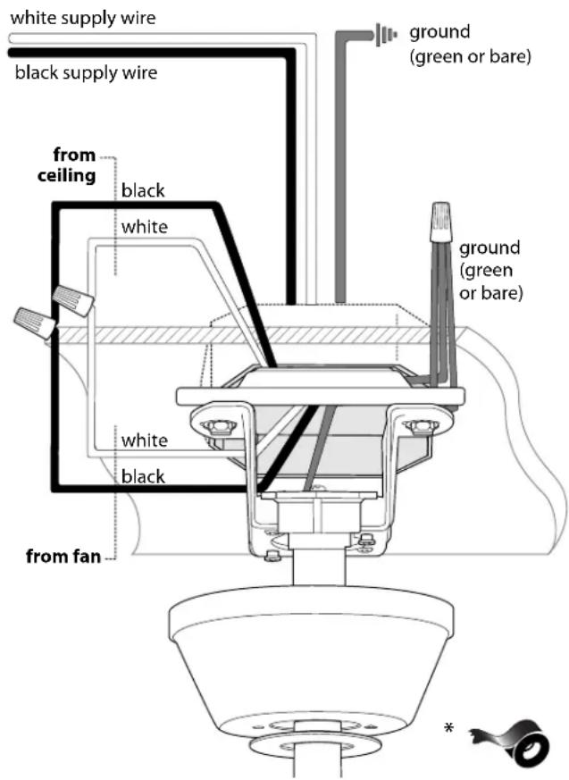
6. Wiring. (cont.)
[PLEASE NOTE: Wall and/or handheld remote control must be used for fan to operate. If you do not wish to use the wall control, please proceed to Section 7 below to continue with fan installation.]
To install wall control, remove existing wall switch. Wire one of the wall controls with wire connectors provided as shown in diagram at right.
*Wrap each wire connector separately with electrical tape as an extra safety measure. Gently push wires and taped wire connectors into outlet box.
Install one 12-volt battery (included) in wall control.
IMPORTANT: Wall control will not function unless battery is installed.
WARNING: Battery is to be inserted with the correct polarity.
Attach wall control to outlet box and secure with screws from original wall switch. Attach plate (included) to wall control using 2 screws provided with the wall control.
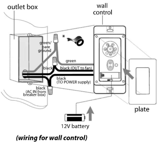
7. Canopy Assembly.
Locate 2 screws on underside of hanging bracket and remove screw closest to the open end of the hanging bracket. Partially loosen the other screw. Lift canopy to hanging bracket. Place rounded part of slotted hole in canopy over loosened screw in hanging bracket and push up. Twist canopy to lock. Re-insert screw that was removed and then tighten both screws securely.
Slide canopy cover up to canopy, aligning rounded part of slotted holes in canopy cover with screwheads in bottom of canopy. Turn canopy cover to the right (clockwise) until it stops.
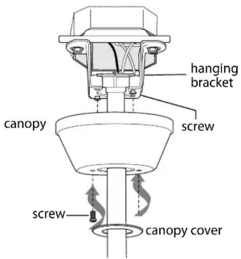
8. Blade Assembly.
WARNING: To reduce the risk of serious bodily injury, DO NOT use power tools to assemble the blades. If screws are overtightened, blades may crack and break.
Locate 18 blade attachment screws/lock washers in one of the hardware packs. Hold blade plate up to one of the blades, aligning holes in blade plate with holes in blade as shown. Place blade arm on UNDERSIDE of blade aligning holes in blade arm with holes in blade and blade plate as shown. Insert 3 blade attachment screws/lock washers from TOPSIDE of blade plate with fingers first and then tighten screws securely with a Phillips screwdriver. Repeat procedure for remaining blades.
Locate blade arm screws/lock washers in hardware pack. Place blade arm on motor plate, aligning blade arm holes and pegs with motor screw holes and alignment holes for pegs. Attach blade arm with blade arm screws/lock washers. Before securing screws permanently, repeat with remaining blade arms. Securely tighten all screws.
NOTE: Tighten blade arm screws twice a year.
NOTE: When operating the fan in a covered patio location, it is possible for high wind gusts to cause the fan to stop briefly. It will then emit a warning beep for 60 seconds and restart at the same setting. If you wish to restart the fan sooner, you may push the SPEED button during the 60-second warning beep.
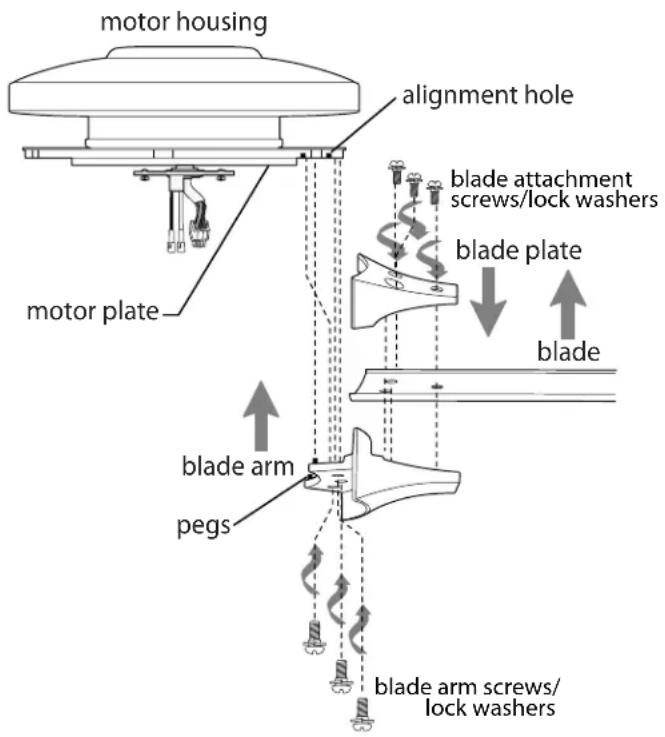
9. Light Kit Assembly.
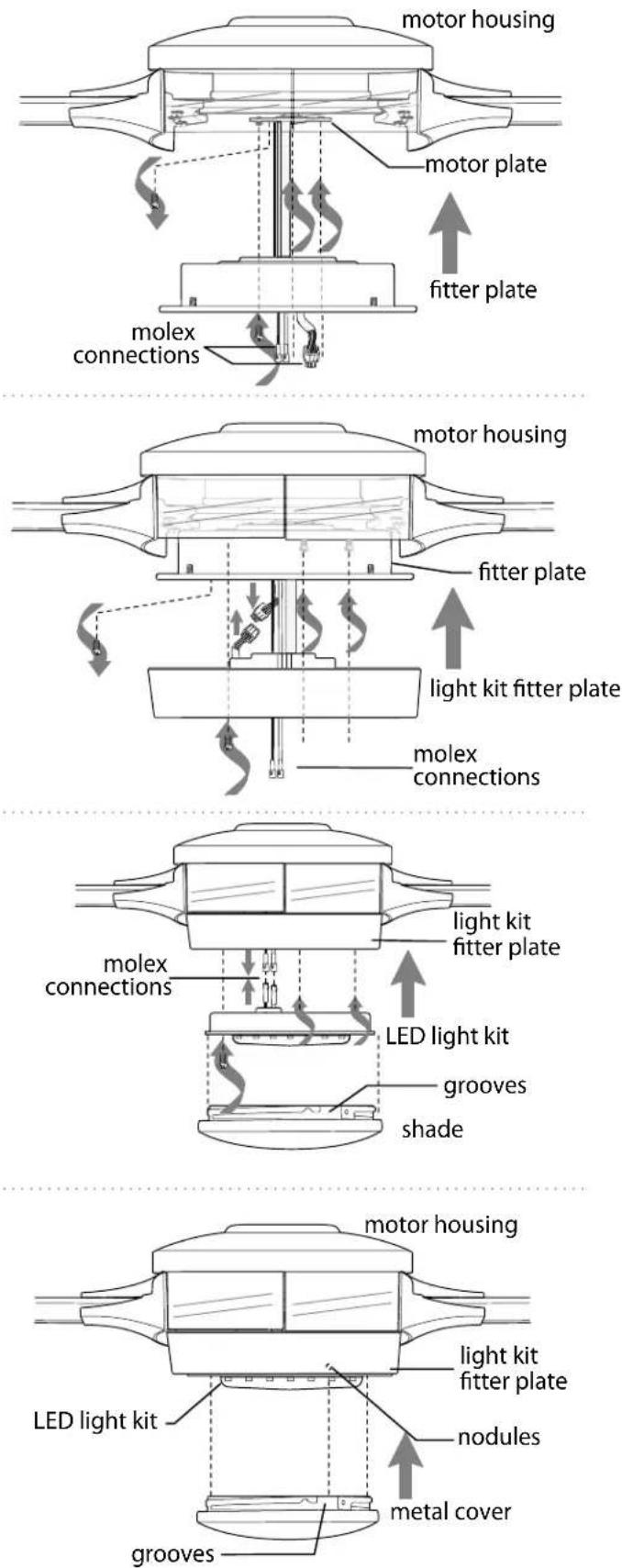
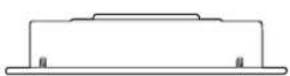
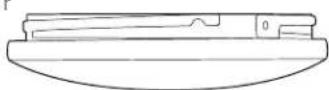
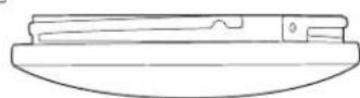
Remove 1 screw from motor plate on underside of motor housing and partially loosen the other 2 screws. Align slotted holes in fitter plate with loosened screws in motor plate, allowing male plug and molex connections from motor housing to come through hole in middle of fitter plate. Twist fitter plate to lock. Re-insert screw that was just removed and securely tighten all 3 screws with a Phillips screwdriver.
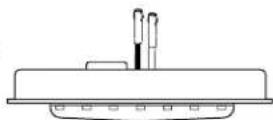
Remove 1 screw from from outer edge of fitter plate and partially loosen the other 2 screws. Connect male plug from motor housing to female plug from light kit fitter plate, matching up the colors on the male plug with the colors on the female plug for correct fit. Be sure that plugs connect securely. Align slotted holes in light kit fitter plate with loosened screws in fitter plate, allowing molex connections from motor housing to come through hole in middle of light kit fitter plate. Twist light kit fitter plate to lock. Re-insert screw that was just removed and securely tighten all 3 screws with a Phillips screwdriver.
Remove 1 screw from from underside of light kit fitter plate and partially loosen the other 2 screws.
If you wish to use the light kit, connect WHITE wire from LED light kit to WHITE wire from motor housing. Connect BLACK wire from LED light kit to BLUE (or BLACK) wire from motor housing. Be sure that molex connections snap together completely.
Carefully arrange wiring within lit kit fitter plate. Align slotted holes in LED light kit with loosened screws in light kit fitter plate. Twist LED light kit to lock. Re-insert screw that was previously removed and tighten all 3 screws securely.
Align grooves on shade with nodules on inside of LED light kit and push up gently on shade. Twist shade to the RIGHT (clockwise) until shade locks into place. Pull down VERY GENTLY on shade to make sure that shade is secure.
If you do NOT wish to use the light kit, locate slots on metal cover and align with nodules inside LED light kit. Gently push up on metal cover and turn to the RIGHT (clockwise) until it no longer turns.
WARNING: Do NOT connect the molex connections for the LED light kit if you do NOT wish to use the light.
WARNING: Metal cover will be HOT if light is left on.
10. Handheld Remote Control Assembly.
IN ORDER TO USE THE HANDHELD REMOTE CONTROL, PLEASE CONTINUE WITH SECTION 10 for remote control assembly instructions. If you have already installed the wall control but do not wish to use the handheld remote control, please proceed to Section 11.
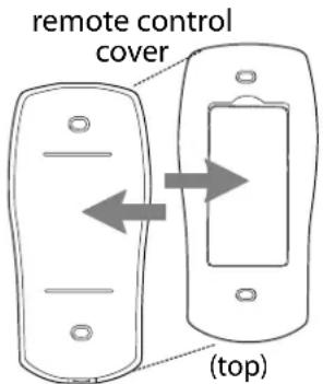
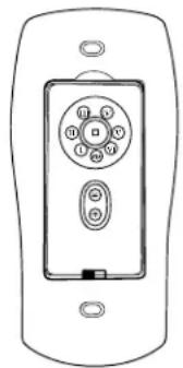
Gently pull on remote control cover to separate top and bottom parts. [Refer to diagram 1.]
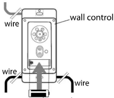
In order to use wall control as a handheld remote control, cut each wire on wall control (that was not previously used)--use wire cutters to cut off each wire as close to the wall control as possible. [Refer to diagram 2.]
Install one 12-volt battery (included) in wall control. [Refer to diagram 2.]
WARNING: Battery is not rechargeable.
Non-rechargeable batteries are not to be recharged. Batteries are to be inserted with the correct polarity.
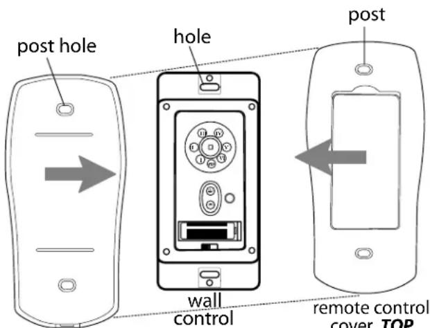
Align holes in wall control with posts located on inside of TOP part of remote control cover and press together firmly. Place wall control into BOTTOM part of remote control cover, aligning posts in top of remote control cover with post holes in the bottom.
[Refer to diagram 3.]
(NOTE: Make sure to align narrower ends of remote control cover before closing.) Squeeze top and bottom of remote control cover together until you hear a click at each end, indicating that the remote control cover has closed completely.
IMPORTANT: Store the handheld remote control away from excess heat or humidity. To prevent damage to handheld remote control, remove the battery if remote control will not be used for long periods.
NOTE: Remove batteries with low or no charge and dispose of properly.
CAUTION: "DO NOT DISPOSE OF BATTERIES IN FIRE, BATTERIES MAY EXPLODE OR LEAK." - When disposing of household alkaline batteries, it is best to check with your local and state recycling or household hazardous waste coordinators concerning the specifics of the program in your area. You may also locate a recycling center by calling 1-800-8-BATTERY or 1-877-2-RECYCLE or visit www.epa.gov/epawaste/index.htm or www.earth911.org for more information.
WARNING: Choking Hazard - Small parts. Keep battery away from children.
diagram 1
(bottom)
12V battery
diagram 2
remote control cover, BOTTOM
diagram 3
11. Automated Learning Process./Activating Code.
CAUTION: The wall and/or handheld remote control can be programmed to multiple receivers or fans. If this is not desired, turn wall switch off to any other programmable receiver or fan.
Restore electrical power and then, if using wall control, set slider switch on wall control to the ON position. Within 60 seconds of turning on the wall control, press and hold the fan SET button on the wall control for 5 seconds (or until light blinks twice or fan blades begin to turn).
Turn power off again for at least 5 seconds and then turn power back on. Within 60 seconds of restoring the power, press and hold the fan SET button on the handheld remote control for 5 seconds or until light blinks twice.
Test the light and fan functions to confirm the learning process is complete--see Section 14.
Select a faceplate (almond or white) and press firmly onto front of wall control that was previously installed to the outlet box on the wall. [Refer to diagram 1.]
Attach black faceplate to front of handheld remote control; press down firmly. [Refer to diagram 2.]
diagram 1
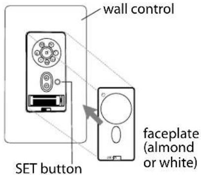
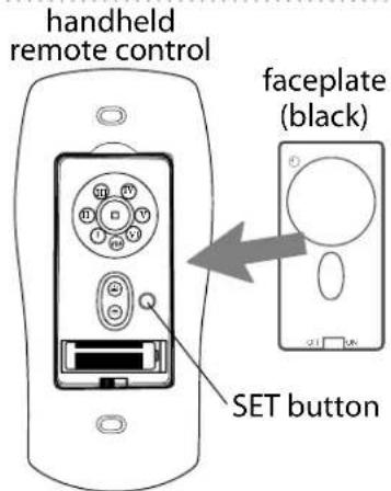
diagram 2
12. Remote/Wall Control Operation.
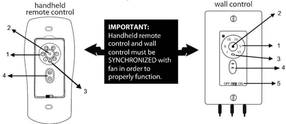
flowchart
graph LR
    A["handheld remote control"] -->|IMPORTANT: Handheld remote control and wall control must be SYNCHRONIZED with fan in order to properly function.| B["wall control"]
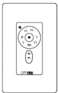
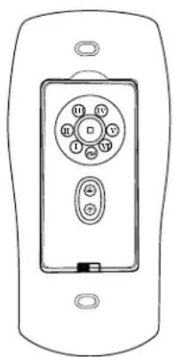
Fan SPEED control buttons--1:
Fan OFF button--2:
REVERSE function button--3:
LIGHTING button--4:
ON/OFF slider switch--5:
Use to control the ceiling fan speed 1-6
Use to turn the fan off
Use to control fan direction
Use to control down-light and/or up-light (if applicable)
[Wall control only] Use to turn wall control ON or OFF
IMPORTANT: The Automated Learning Process takes approximately 5 minutes to complete. Please leave the fan "ON" for the duration of the 5-minute programming and do NOT use the remote control or turn off the power during this time. The fan will cycle through ALL SIX (6) speeds in forward and reverse and will then stop automatically after the learning process is complete.
13. Smart Ceiling Fan Wi-Fi Control. (Optional)
Without Wi-Fi activation, you will not enjoy the expanded features and functionality of your ceiling fan: Breeze speed setting, Creating Schedules and Voice Activation.
To enjoy all the potential of your new device, refer to the following steps to complete Smart setup.
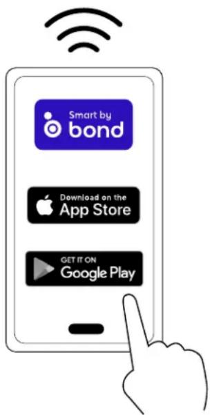
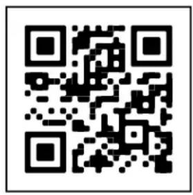
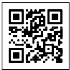
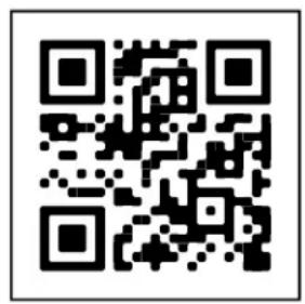
- Download the Bond Home App, available on the Google Play Store and Apple App Store, or use the QR code to download the app.
- Open the Bond application.
- If you already have a Bond account, simply log in and continue to Step 4. If you do not have a Bond account, press "Create Account" and enter your name, email and create a password.
- Select "+" to add a device.
- Select "Smart By Bond" (SBB).
- Select this smart ceiling fan.
- Once the Bond application connects to the fan, select "CONTINUE" to proceed.
- Test the fan functions:
- You have the option to disable the light function if your fan does not have a light.
- Select "YES, IT WORKS."
- Specific information about your fan:
-Select "Location" and choose from one of the predefined entries or add your own by selecting "OTHER". When finished, select "Save".
- Select device name and enter the name for your device. When finished, select "OK" to save.
PLEASE NOTE: This name will be used for integrations so a simple, easy-to-remember name is best.
- Select "Continue".
- Select the Wi-Fi network you would like to connect the SBB to.
- Enter the Wi-Fi password and select "OK".
- If there is an issue with the connection or wrong password is entered, you will receive an error message. Select "OK, I've Got It".
- Once the connection is made, select "DONE".
- If the SBB fan is not displayed in the Bond application, swipe down to refresh.
For assistance at any time during this process, go to the "Help" section of the app:
- Tap on "Settings"
- Tap on "Help Center"
- Choose "Open a Ticket" or "Live Chat"
14. Testing Your Fan.
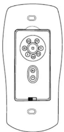
It is recommended that you test fan before finalizing installation. Restore power from circuit box and wall switch (if applicable). Test wall control (optional installation) by locating ON/OFF slider switch on wall control, then set to the ON position. Test light and dimmer function and then test fan speeds. Next, locate handheld remote control. Test fan speeds with the different fan speed buttons (I - VI) on handheld remote control. Test the light ON/OFF function by pressing the button; test the dimmer function by pressing the button and holding it down for up to 5 seconds. If the wall and/or remote control operates all of the functions of the fan, battery/batteries has/have been installed correctly. If the wall and/or remote controls do (does) not operate all of the fan functions, refer to "Troubleshooting" section to solve any issues before contacting Customer Service.
Fan must be on LOW before setting the fan in reverse. Use ➕ button to recirculate air depending on the season. A ceiling fan will allow you to raise your thermostat setting in summer and lower your thermostat setting in winter without feeling a difference in your comfort.
NOTE: If the wall control/handheld remote control interferes with other appliances, activate a new code on the wall control/ handheld remote control by turning the power off first. Go back to the instructions for the SET button in Section 11 (page 13).
IMPORTANT: Handheld remote control and wall control must be synchronized with fan in order to properly function.
NOTE: When operating the fan in a covered patio location, it is possible for high wind gusts to cause the fan to stop briefly. It will then emit a warning beep for 60 seconds and restart at the same setting. If you wish to restart the fan sooner, you may push the SPEED button during the 60-second warning beep.
natural_image
Line drawing of a remote control panel with buttons and ports (no text or symbols)Troubleshooting.
WARNING: Failure to disconnect power supply prior to troubleshooting any wiring issues may result in serious injury.
Problem: Fan fails to operate.
Solutions:
- Check wall switch to fan.
- Check to be sure fan is wired properly.
- Learning process between fan, remote control and, if applicable, wall control may not have been successful and code was not activated. Turn off power and repeat instructions for SET button in Section 11 (page 13).
- Check that red light on remote control turns on when a button is pressed indicating that the battery is good.
- Verify that male and female plugs are connected properly.
- When operating the fan in a covered patio location, it is possible for high wind gusts to cause the fan to stop briefly. It will then emit a warning beep for 60 seconds and restart at the same setting. If you wish to restart the fan sooner, you may push the SPEED button during the 60-second warning beep.
Problem: Light kit not lighting.
Solutions:
- Check wall switch to fan.
- Check to be sure wires in canopy are wired properly.
- Verify that molex connections in LED light kit are connected properly.
- Learning process between fan, remote control and, if applicable, wall control may not have been successful and code was not activated. Turn off power and repeat instructions for SET button in Section 11 (page 13).
Problem: Fan operates but light fails.
Solutions:
- Check to be sure wires in canopy are wired properly.
- Verify that molex connections in LED light kit are properly connected.
Problem: Fan and light fail to operate with remote control.
Solutions:
- Check battery power to remote control.
- Learning process between fan, remote control and, if applicable, wall control may not have been successful and code was not activated. Turn off power and repeat instructions for SET button in Section 11 (page 13).
Problem: Fan wobbles.
Solutions:
- Use the balancing kit provided in one of the hardware packs. If no blade balancing kit is provided, please call Customer Support, 1-800-486-4892, to request one.
- Check to be sure set screw(s) on motor housing yoke is (are) tightened securely.
Warranty.
CRAFTMADE™ LIFETIME LIMITED WARRANTY:
CRAFTMADE warrants this fan to the original household purchaser for indoor use under the following provisions:
1-YEAR WARRANTY: CRAFTMADE will replace or repair any fan which has faulty performance due to a defect in material or workmanship. Contact Craftmade Customer Service at 1-800-486-4892 to arrange for return of fan. Return fan, shipping prepaid, to Craftmade. We will repair or ship you a replacement fan, and we will pay the return shipping cost.
5-YEAR WARRANTY: CRAFTMADE will repair or replace, at no charge to the original purchaser, any fan motor that fails to operate satisfactorily when failure results from normal use.
RETURN FAN MOTOR ONLY, shipping prepaid, to Craftmade Industries. We will repair or ship purchaser a replacement motor and Craftmade will pay the return shipping cost. 6-YEAR to LIFETIME LIMITED WARRANTY: CRAFTMADE will repair the fan, at no charge for labor only to the original purchaser, if the fan motor fails to operate satisfactorily when failure results from normal use. Parts used in the repair will be billed to the purchaser at prevailing prices at time of repair.
The purchaser shall be responsible for all costs incurred in the removal, reinstallation and shipping of the product for repairs.
This warranty does not apply when damage from mechanical, physical, electrical or water abuse results in causing the malfunction. Deterioration of finishes or other parts due to time or exposure to salt air is specifically exempted under this warranty.
Neither Craftmade nor the manufacturer will assume any liability resulting from improper installation or use of this product. In no case shall the company be liable for any consequential damages for breach of this, or any other warranty expressed or implied whatsoever. This limitation as to consequential damages shall not apply in states where prohibited.
Parts Replacement.
For parts and information, please refer to
"Parts Inventory" on page 4.
Craftmade Customer Support:
1-800-486-4892
www.craftmade.com
CRAFTMADE
CRAFTMADE™
LISEZ CES INSTRUCTIONS ET CONSERVEZ-LES POUR USAGE FUTUR
natural_image
Two black-and-white illustrations of a ceiling fan with blades and hub, showing structural details (no text or symbols)natural_image
Line drawing of an open box with a U-shaped cutout on the side (no text or symbols)p
r
t
V
q
5
natural_image
Line drawing of a remote control device with buttons and ports (no text or symbols)Dépannage
natural_image
Silhouette of a black overhead fan with five blades and a central hub, emitting beams radiating outward (no text or symbols)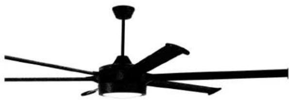
natural_image
Black and white illustration of a classic multi-lane ceiling fan with five blades (no text or symbols)Prost
Guía de instalación
Para modelos:
PRT78
PRT102
PRT120
ADVERTENCIA:
natural_image
Line drawing of a box with open lid and internal slot (no text or symbols)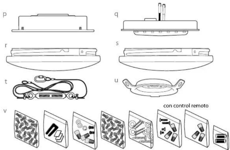

RECORDATORIO IMPORTANTE:
natural_image
Simple geometric diagram of a six-bladed fan or blade on a grid background (no text or symbols)3,66m - 6,1m
12 pies - 20 pies
3,66m - 6,1m
12 pies - 20 pies
natural_image
Line drawing of a remote control device with buttons and ports (no text or symbols)- Prost
- Installation Guide
- Activating Your New Smart Fan; Downloading the Bond Home App
- SAFETY TIPS.
- READ ALL INSTRUCTIONS AND SAFETY INFORMATION CAREFULLY BEFORE INSTALLING YOUR FAN AND SAVE THESE INSTRUCTIONS.
- Unpacking Your Fan.
- Parts Inventory.
- Installation Preparation.
- Installation requires these tools:
- Mounting Plate & Hanging Bracket Installation.
- Mounting Plate & Hanging Bracket Installation. (cont.)
- Fan Assembly.
- ["Fan Assembly" continued on next page.]
- Fan Assembly. (cont.)
- Wiring.
- Wiring. (cont.)
- Canopy Assembly.
- Blade Assembly.
- Light Kit Assembly.
- Handheld Remote Control Assembly.
- Automated Learning Process./Activating Code.
- Remote/Wall Control Operation.
- Smart Ceiling Fan Wi-Fi Control. (Optional)
- Testing Your Fan.
- Troubleshooting.
- Solutions:
- Warranty.
- Parts Replacement.
- CRAFTMADE™
- Dépannage
- Guía de instalación
- RECORDATORIO IMPORTANTE:
Brand : Craftmade
Model : PRT78
Category : Fan