
ACS-23105-80H - Compressor Mi-T-M - Free user manual and instructions
Find the device manual for free ACS-23105-80H Mi-T-M in PDF.

| Product type | Electric air compressor |
| Brand | Mi-T-M |
| Model | ACS-23105-80H |
| Tank capacity | 80 gallons (300 litres) |
| Tank type | Horizontal or vertical depending on configuration |
| Dimensions (approx.) | 132 x 65 x 135 cm (horizontal model) |
| Net weight (estimated) | Approximately 250 kg |
| Motor power | 5 HP (3.7 kW) or 7.5 HP (5.6 kW) depending on model |
| Supply voltage | 230 V single-phase / 200 V three-phase / 230-460 V three-phase depending on model |
| Pump type | 2-stage |
| Motor speed | 1750 rpm (for 5 HP motor) |
| Maximum pressure | Up to 10 bar (145 PSI) according to factory setting |
| Main functions | Air compression for pneumatic tools, spraying, inflation |
| Maintenance | Daily tank drain, oil change every 1000 hours, air filter cleaning |
| Safety | Safety valve, mandatory grounding, thermal overload protection |
| Spare parts | Air filter, belt, check valve, pressure switch |
| Repairability | Entrusted to a Mi-T-M authorized service center |
| Warranty | 2 years tank, 5 years pump (3 years 100%, then 90%, 80%), 6 months pressure switch |
| General information | Use non-detergent SAE 30 oil, do not use in wet weather |
Frequently Asked Questions - ACS-23105-80H Mi-T-M
User questions about ACS-23105-80H Mi-T-M
0 question about this device. Answer the ones you know or ask your own.
Ask a new question about this device
Download the instructions for your Compressor in PDF format for free! Find your manual ACS-23105-80H - Mi-T-M and take your electronic device back in hand. On this page are published all the documents necessary for the use of your device. ACS-23105-80H by Mi-T-M.
USER MANUAL ACS-23105-80H Mi-T-M
80 GALLON INDUSTRIAL AIR COMPRESSOR
OPERATOR'S MANUAL
PARTS LIST

CAUTION
RISK OF INJURY! READ ENTIRE MANUAL BEFORE OPERATING! THIS MANUAL IS AN IMPORTANT PART OF THE AIR COMPRESSOR AND MUST REMAIN WITH THIS UNIT!
CONTENTS
INTRODUCTION 3
IMPORTANT SAFETY INSTRUCTIONS 4
AIR COMPRESSOR SPECIFICATIONS 8
PUMP/MOTOR SPECIFICATIONS....8
AVAILABLE IN HORIZONTAL TANK, VERTICAL TANK AND BASE MOUNT UNITS 8
MOTOR SPECS 8
AIR COMPRESSOR FEATURES....9
80 GALLON VERTICAL COMPRESSOR 2 STAGE INDUSTRIAL 9
AIR COMPRESSOR FEATURES....10
80 GALLON HORIZONTAL COMPRESSOR 2 STAGE INDUSTRIAL....10
EXPLODED VIEW & EXPLANATION OF AIR COMPRESSOR FEATURES....11
PREPARATION INSTRUCTIONS....14
INITIAL SET-UP: 14
LOCATION: 14
ELECTRICAL....15
PRE-START CHECKLIST: 15
OPERATING INSTRUCTIONS....17
START-UP: 17
SHUTDOWN: 17
MAINTENANCE INSTRUCTIONS....18
TROUBLESHOOTING....19
STATEMENT OF WARRANTY 22
⚠ WARNING
⚠ WARNING: This product can expose you to chemicals including Lead, which is known to the State of California to cause cancer and birth defects or other reproductive harm. For more information go to www.P65Warnings.ca.gov
⚠ WARNING
⚠ WARNING: This product can expose you to chemicals including carbon monoxide, which is known to the State of California to cause birth defects or other reproductive harm. For more information go to www.P65Warnings.ca.gov
INTRODUCTION
Congratulations on the purchase of your new Mi-T-M® Air Compressor! You can be assured your Mi-T-M® Air Compressor was constructed with the highest level of precision and accuracy. Each component has been rigorously tested by technicians to ensure the quality, endurance and performance of this air compressor.
This operator's manual was compiled for your benefit. By reading and following the simple safety, installation and operation, maintenance and troubleshooting steps described in this manual, you will receive years of troublefree operation from your new Air Compressor. The contents of this manual are based on the latest product information available at the time of publication. The Manufacturer reserves the right to make changes in price, color, materials equipment, specifications or models at any time without notice.

IMPORTANT!
A "DANGER, WARNING or CAUTION" safety warning will be surrounded by a "SAFETY ALERT BOX". This box is used to designate and emphasize Safety Warnings that must be followed when operating this air compressor. Accompanying the safety warnings are "Signal Words" which designate the degree or level of hazard seriousness. The "Signal Words" used in this manual are as follows:
DANGER: INDICATES AN IMMINENTLY HAZARDOUS SITUATION WHICH, IF NOT AVOIDED, WILL RESULT IN DEATH OR SERIOUS INJURY.
WARNING: INDICATES A POTENTIALLY HAZARDOUS SITUATION WHICH, IF NOT AVOIDED, COULD RESULT IN DEATH OR SERIOUS INJURY.
CAUTION: INDICATES A POTENTIALLY HAZARDOUS SITUATION WHICH, IF NOT AVOIDED MAY RESULT IN MINOR OR MODERATE INJURY OR DAMAGE TO THE AIR COMPRESSOR.
The symbols set below are "Safety Alert Symbols". These symbols are used to call attention to items or procedures that could be dangerous to you or other persons using this equipment.


ALWAYS PROVIDE A COPY OF THIS MANUAL TO ANYONE USING THIS EQUIPMENT. READ ALL INSTRUCTIONS IN THIS MANUAL AND ANY INSTRUCTIONS SUPPLIED BY MANUFACTURERS OF SUPPORTING EQUIPMENT BEFORE OPERATING THIS AIR COMPRESSOR AND ESPECIALLY POINT OUT THE "SAFETY WARNINGS" TO PREVENT THE POSSIBILITY OF PERSONAL INJURY TO THE OPERATOR.
Once the unit has been uncrated, immediately write in the serial number of your unit in the space provided below.
SERIAL NUMBER
Inspect for signs of obvious or concealed freight damage. If damage does exist, file a claim with the transportation company immediately. Be sure that all damaged parts are replaced an that the mechanical and electrical problems are corrected prior to operation of the unit. If you require service, contact Mi-T-M® Customer Service.
Mi-T-M® Corporation, 50 Mi-T-M Drive, Peosta, IA 52068
563-556-7484 / 800-553-9053 / Fax 563-556-1235
Monday - Friday 8:00 a.m. - 5:00 p.m. CST
Please have the following information available for all service calls:
- Model Number
- Serial Number
- Date and Place of Purchase
IMPORTANT SAFETY INSTRUCTIONS

READ ALL SAFETY WARNINGS BEFORE USING AIR COMPRESSOR

Hazard Potential Consequence Prevention
RISK OF ELECTRIC SHOCK OR ELECTROCUTION
natural_image
Black-and-white icon of a hand with a lightning bolt and smoke trail, symbolizing electrical hazard (no text or symbols)Serious injury or death could occur if the air compressor is not properly grounded. Your air compressor is powered by electricity and may cause electric shock or electrocution if not used properly.
Electrical shock may occur if the air compressor is not operated properly.
Serious injury or death may occur if electrical repairs are attempted by unqualified persons.
Installation of this unit, including all electrical connections, must comply with all local, state and national codes.
This product must be grounded. Connect to a GFCI circuit breaker when available. If the unit should malfunction or breakdown, grounding provides a path of least resistance for electric current to reduce the risk of electric shock. Do not ground to a gas supply line.
Improper connection of the equipment-grounding conductor can result in a risk of electrocution. Check with a qualified electrician or service personnel if you are in doubt as to whether the system is properly grounded.
Always be certain the unit is receiving proper voltage (+/- 5% of the voltage listed on the name-plate). Before installing electrical connections, be certain the power switches are in the "OFF" position.
Keep all connections dry and off the ground.
Never operate air compressor in wet conditions.
Never operate air compressor with safety guards/covers removed or damaged.
Any electrical wiring or repairs performed on this air compressor should be done by Authorized Service Personnel in accordance with National and Local electrical codes.
Before opening any electrical enclosure, always shut off the air compressor, relieve pressure and unplug the air compressor from the power source. Allow air compressor to cool down. Never assume the air compressor is safe to work on just because it is not operating. It could restart at any time! Service in a clean, dry, flat area.
IMPORTANT SAFETY INSTRUCTIONS
| Hazard Potential Consequence Prevention | ||
RISK OF EXPLOSION OR FIRE  | Serious injury or death may occur from normal electrical sparks in motor and pressure switchSerious injury may occur if any air compressor ventilation openings are restricted, causing the air compressor to overheat and start a fire. | Always operate air compressor in a well ventilated area free of flammable vapors, combustible dust, gases or other combustible materials.DO NOT SMOKE if spraying flammable material. Locate the air compressor at least 20 feet away from the spray area. (An additional hose may be required.)Never place objects against or on top of air compressor. Oper- ate air compressor at least 12 inches away from any wall or obstruction that would restrict proper ventilation. |
RISK OF BURSTING | Serious injury or death may occur from an air tank explosion if air tanks are not properly maintained.Serious injury may occur from an air compressor malfunction or exploding accessories if incorrect system components, attachments or accessories are used. | Drain air tank daily or after each use to prevent moisture buildup in the air tank.If air tank develops a leak, replace the air tank immedi- ately. Never repair, weld or make modifications to the air tank or its attachments. Use only genuine manufacturer repair parts for your air compressor.Never make adjustments to the factory set pressures.Never exceed manufacturers maximum allowable pressure rat- ing of attachments.Because of extreme heat, do not use plastic pipe or lead tin sol- dered joints for a discharge line.Never use air compressor to in- flate small, low pressure objects such as toys. |
IMPORTANT SAFETY INSTRUCTIONS
Hazard Potential Consequence Prevention
| [RISK TO BREATHING Serious injury or death could occur from inhaling compressed air. The air stream may contain carbon monoxide, toxic vapors or solid particles.Sprayed materials such as paint, paint solvents, paint re-mover, insecticides, weed kill-ers, etc. contain harmful vapors and poisons. | Never inhale air from the air compressor either directly or from a breathing device connected to the air compressor.Operate air compressor only in a well ventilated area. Follow all safety instructions provided with the materials you are spraying. Use of a respirator may be required when working with some materials. | |
[RISK OF BURNS | Serious injury could occur from touching exposed metal parts. These areas can remain hot for some time after the air compressor is shutdown. | Never allow any part of your body or other materials to make contact with any exposed metal parts on the air compressor. |
[RISK FROMFLYING OBJECTS | Serious injury can occur from loose debris being propelled at a high speed from the compressed air stream.Soft tissue damage can occur from the compressed air stream. | Always wear safety glasses to shield the eyes from flying debris.Never point the air stream at any part of your body, anyone else or animals.Never leave pressurized air in the air compressor. Shut off air compressor and relieve pressure when storing or attempting maintenance.Always maintain a safe distance from people and animals while operating the air compressor. |
IMPORTANT SAFETY INSTRUCTIONS
| Hazard Potential Consequence Prevention | ||
| RISK FROM MOVING PARTS | Risk of bodily injury from moving parts. This air compressor cycles (Starts/Stops) automatically when the pressure switch is in the "On/Auto" position. | Before performing maintenance, always turn off air compressor.Bleed pressure from the air hose and disconnect from the electrical source. All repairs to the air compressor should be made by an Authorized Service person.Never assume the air compressor is safe to work on just because it is not operating. It could restart at any time!Do not operate without protective covers/guards. Always unplug the air compressor before removing any guard. Replace damaged covers/guards before using the air compressor. |
| RISK FROM NEGLIGENCE | Risk of injury from negligent use. | Never allow children or adolescents to operate this air compressor!Stay alert-watch what you are doing. Do not operate the air compressor when fatigued or under the influence of alcohol or drugs.Know how to stop the air compressor. Be thoroughly familiar with controls. |
| RISK OF DAMAGE TO AIR COMPRESSOR | Risk of major repair. | Do not operate air compressor without an air filter.Do not operate air compressor in a corrosive environment.Always operate the air compressor secured to a concrete surface to prevent the air compressor from falling.Follow all maintenance instructions listed in this manual. |

! SAVE THESE INSTRUCTIONS !

PUMP/MOTOR SPECIFICATIONS
| HP Pump | Pump RPM | Motor RPM | |
| 5 3-0298 | 805 | 1750 | |
| 5 3-0312 | 860 | 1750 | |
| 7.5 3-0312 | 1250 | 1750 |
AVAILABLE IN HORIZONTAL TANK, VERTICAL TANK AND BASE MOUNT UNITS
| Bolt DownL x W | DimensionsL x W x H | |
| Base 21" x | 13.5" 32.5" x | 19" x 27.5" |
| Horizontal | 20.75" x 23.5" | 52" x 25.5" x 53" |
| Vertical | 15.63" x 15.63" | 33" x 25" x 73" |
MOTOR SPECS
| HP | Voltage | Amps Phase | |
| 5 | 230 | 23.0 | 1 |
| 5 | 200 | 16.1 | 3 |
| 5 230/460 | 13.8/6.9 3 | ||
| 7.5 | 230 | 31.0 | 1 |
| 7.5 | 200 | 23.0 | 3 |
| 7.5 | 230/460 | 20/10 | 3 |
AIR COMPRESSOR FEATURES
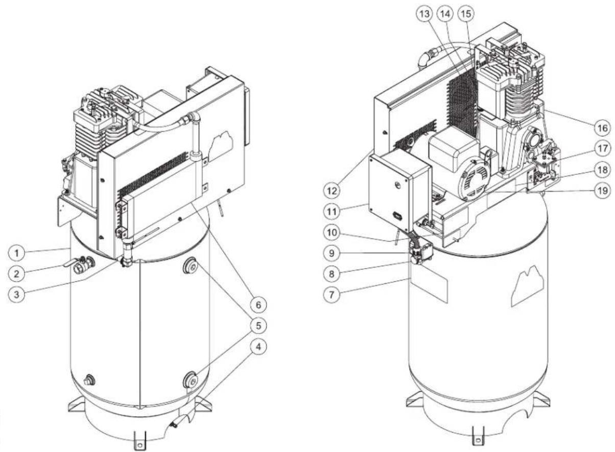
80 GALLON VERTICAL COMPRESSOR 2 STAGE INDUSTRIAL
(DOES NOT INCLUDE POWER CORD, POWER PLUG, PRESSURE REGULATOR)
80 GAL VERTICAL 041612 KMD
- Air Tank Assembly
- Outlet Fitting
- Pump Discharge Line
- Pneumatic Tank Drain Option (M Series Only)
- Tank Inspection Openings
- Aftercooler After Cooler (M Series Only)
- Decal - Danger/Warning/Caution
- Air Tank Pressure Gauge
- Motor Pressure Switch
-
Decal - Maintenance Instructions
-
Starter Option
- Beltguard
- Oil Fill Port
- Air Intake Filter
- Ventilation Openings
- Air Compressor Pump
- Low Oil Shutdown Option (M Series Only)
- Decal - Operating Instructions
- Electric Motor
AIR COMPRESSOR FEATURES
80 GALLON HORIZONTAL COMPRESSOR 2 STAGE INDUSTRIAL
(DOES NOT INCLUDE POWER CORD, POWER PLUG, PRESSURE REGULATOR)
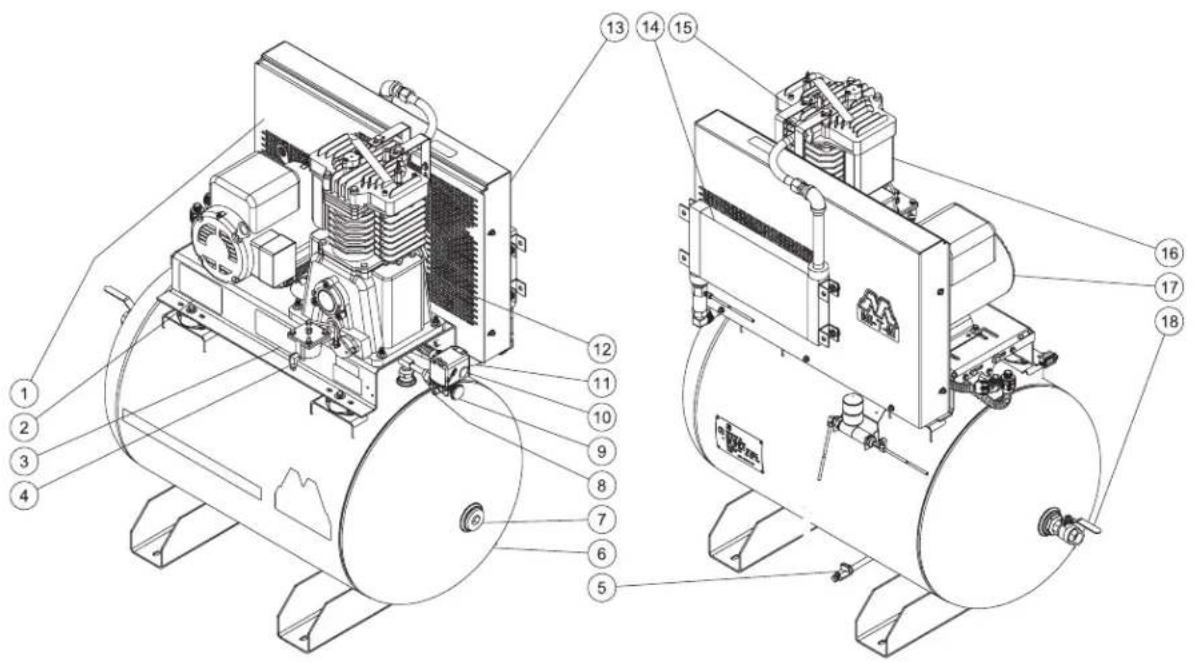
- Decal - Caution/Warning/Danger*
- Decal - Maintenance Instructions*
- Decal - Operating Instructions*
- Low Oil Shutdown Option (M Series Only)
- Pneumatic Tank Drain Option (M Series Only)
- Air Tank Assembly
- Tank Inspection Openings
- Safety Relief Valve
- Air Tank Pressure Gauge
* Parts included on Base Mount unit
- Motor Pressure Switch
- Pump Discharge Line
- Ventilation Openings*
- Beltguard*
- Aftercooler Option (M Series Only)
- Air Compressor Pump*
- Air Intake Filter*
- Electric Motor*
- Outlet Fitting
EXPLODED VIEW & EXPLANATION OF AIR COMPRESSOR FEATURES
AIR TANK DRAIN VALVE: The drain valve is used to remove moisture from the air tank(s) after the air compressor is shut off. NEVER attempt to open the drain valve when more than 10 PSI of air pressure is in the air tank! To open the drain valve, turn the knob counterclockwise.
OIL SIGHT GLASS: The Oil Sight Glass displays the oil level in the pump. The oil level should be at the center of the Oil Sight Glass. If low, add SAE 30W non-detergent oil.
OIL FILL PORT/VENT: Pour oil into the Oil Fill Port/Vent when required.
natural_image
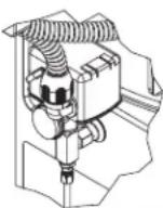
Technical line drawing of a mechanical clamp or bracket assembly (no text or symbols)AIR INTAKE FILTER: This filter is designed to clean air coming into the pump. To ensure the pump continually receives a clean, cool, dry air supply this filter must always be clean and ventilation opening free from obstructions. Replace filter element when necessary.
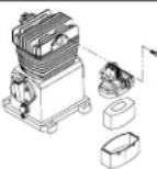
AIR COMPRESSOR PUMP: To compress air, the pistons move up and down in the cylinders.
On the downstroke, air is drawn in through the air intake valves while the exhaust valves remain closed. On the upstroke, air is compressed, the intake valves close and compressed air is forced out through the exhaust valves, into the discharge line, through the check valve and/or the pilot valve and into the air tank.
MOTOR/PRESSURE SWITCH: This switch is used to start or stop the air compressor. Moving the switch to the "Auto" (On) position will provide automatic power to the pressure switch which will allow the motor to start when the air tank pressure is below the factory set "cut-in" pressure. When in the Start/Stop Option, the pressure switch stops the motor when the air tank pressure reaches the factory set "cut-out" pressure. For safety purposes, this switch also has a pressure release valve located on the side of the switch designed to automatically release compressed air from the
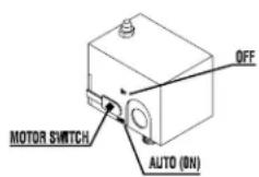
air compressor pump head and its discharge line when the air compressor reaches "cut-out" pressure or is shut off. This allows the motor to restart freely. Moving the switch to the "Off" position will remove power from the pressure switch and stop the air compressor.
SAFETY RELIEF VALVE: This valve is designed to prevent system failures by relieving pressure from the system when the compressed air reaches a predetermined level. The valve is preset by the manufacturer and must not be modified in any way. To verify the valve is working properly, pull on the ring. Air pressure should escape. When the ring is released, it will reset.
AIR TANK PRESSURE GAUGE: The air tank pressure gauge indicates the reserve air pressure in the air tank.
AFTER COOLER: (M Series Only) Removes up to 65% of the moisture from discharged compressor air, it also lowers the gas temperature within 20 degrees of ambient.
EXPLODED VIEW & EXPLANATION OF AIR COMPRESSOR FEATURES
STARTER: the Motor starter provides thermal overload protection. The starter is required from on motors 5 Hp and above.
natural_image
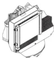
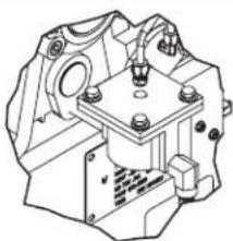
Isometric line drawing of a mechanical housing or enclosure with mounting holes and structural details (no text or symbols)LOW OIL SHUT DOWN: (M Series Only) the low oil sensor shuts the unit down when the oil levels fall below an adequate level.
natural_image
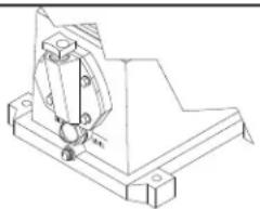
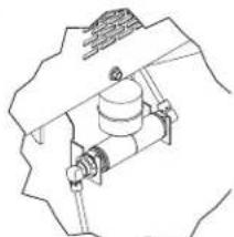
Technical line drawing of a mechanical assembly with no visible text or symbolsVIBRATION ISOLATOR PADS: Isolators protect the unit from vibration during use. They also make installation on unlevel surfaces easier.

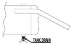
PNEUMATIC DRAIN: (M Series Only) Drains liquid from tank automatically as the water level rises in the tank.
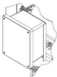
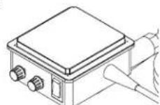
natural_image
Pure mechanical diagram showing a cylindrical component mounted on a base, without any text, numbers, or symbols.ELECTRIC DRAIN: Drains liquid form the tank using a timer for frequency and duration of drain.

WARNING

THE FOLLOWING PAGES CONTAIN OPERATING AND MAINTENANCE INSTRUCTIONS.
DO NOT ATTEMPT TO OPERATE THIS AIR COMPRESSOR UNTIL YOU HAVE READ AND UNDERSTOOD ALL SAFETY PRECAUTIONS AND INSTRUCTIONS LISTED IN THIS MANUAL.
INCORRECT OPERATION OF THIS UNIT CAN CAUSE SERIOUS INJURY!!
DO NOT ALTER OR MODIFY THIS EQUIPMENT IN ANY MANNER!
PREPARATION INSTRUCTIONS
INITIAL SET-UP:
- Read safety warnings before setting-up air compressor.
- Ensure the oil level in the air compressor pump is adequate. If low, add SAE-30W non-detergent oil.

WARNING RISK OF EXPLOSION OR FIRE CAUSING SERIOUS INJURY OR DEATH!

DO NOT ALLOW THE MOTOR OR MOTOR/PRESSURE SWITCH TO COME IN CONTACT WITH FLAMMABLE VAPORS, COMBUSTIBLE DUST, GASES OR OTHER COMBUSTIBLE MATERIALS. AN ELECTRIC SPARK MAY CAUSE AN EXPLOSION OR FIRE.

WHEN USING THE AIR COMPRESSOR FOR SPRAY PAINTING, PLACE THE AIR COMPRESSOR AS FAR AWAY FROM THE WORK AREA AS POSSIBLE.
LOCATION:
- In order to avoid damaging the air compressor, do not incline the air compressor transversely or longitudinally more than 10^ .
- Place air compressor on a concrete surface at least 12 inches away from obstacles that may prevent proper ventilation. Place the flywheel side of the unit toward the wall. Do not place air compressor in an area:
-where there is evidence of oil or gas leaks.
-where flammable gas vapors or materials may be present.
-where air temperatures fall below 32^ F or exceed 104^ F.
-where extremely dirty air or water could be drawn into the air compressor.
-
Distribute air compressor weight evenly. Excessive vibration can weaken the air tank creating a hazard of explosion.
-
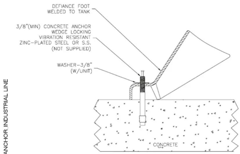
Bolt the air compressor to the concrete surface.
a. Mark the areas through the feet of the air compressor where anchor bolts will be placed.
b. Move the air compressor and drill holes in the marked areas to accept the anchor bolts.
c. Pound the anchor bolts into the pre-drilled holes.
d. Place the air compressor over the anchor bolts.
PREPARATION INSTRUCTIONS
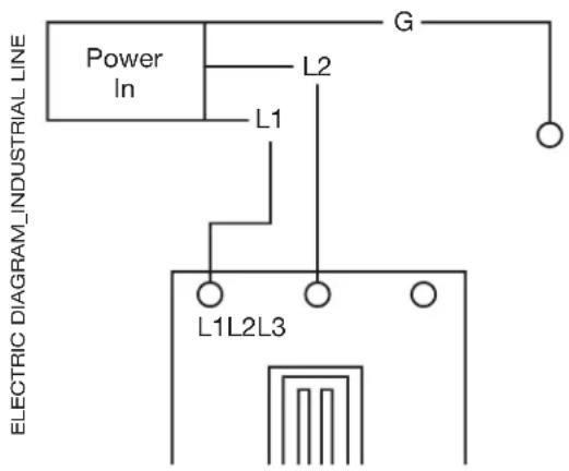
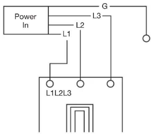
ELECTRICAL
- A qualified electrician MUST hook up the electrical system.
a. Verify the electrical supply at the power source is off.
b. Be certain all switches on the Control Panel and Pressure Switch are in the "OFF" position.
c. Make connections to the terminal as shown below.

DANGER RISK OF ELECTROCUTION!

IMPROPER CONNECTION OF THE EQUIPMENT-GROUNDING CONDUCTOR CAN RESULT IN A RISK OF SHOCK OR ELECTROCUTION. CHECK WITH A QUALIFIED ELECTRICIAN OR SERVICE PERSONNEL IF YOU ARE IN DOUBT AS TO WHETHER THE OUTLET IS PROPERLY GROUNDED. THE WIRE WITH INSULATION HAVING AN OUTER SURFACE THAT IS GREEN WITH OR WITHOUT YELLOW STRIPES IS THE GROUNDING WIRE.

WARNING RISK OF ELECTRICAL SHOCK!

THIS PRODUCT MUST BE GROUNDED. IF THERE SHOULD BE A MALFUNCTION OR BREAKDOWN, GROUNDING PROVIDES A PATH OF LEAST RESISTANCE FOR ELECTRIC CURRENT TO REDUCE THE RISK OF ELECTRIC SHOCK.
1 Phase 3 Phase
PRE-START CHECKLIST:
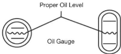
- Check oil level. Add if necessary.
a. For proper lubrication the compressor shall not be operated below the minimum or above the maximum RPM recommended for the various models.
b. Maintain oil level mid-way between the upper and lower lines of the crankcase sight gage. Note the illustration:
c. Stop compressor to add and gauge oil.
d. Do not fill above the upper line and do not operate compressor with oil level below the lower line.
e. Change oil at the first 100 hours of operation and 1000 hours thereafter, or as required. It may be necessary to change oil more frequent due to abnormal humid and contaminated conditions.
PREPARATION INSTRUCTIONS
- Checking Belt Tension. The v-belt(s) should be adjusted so that a declination of about 3/8-1/2 inch will be obtained when it is pushed by a finger at the middle point as shown in figure.

CAUTION: OVER TIGHTENING THE V-BELT(S) WILL RESULT IN OVERLOADING OF THE MOTOR AND BELT FAILURE, WHILE A LOOSE BELT WILL BE SLIPPING AND RESULTING IN AN UNSTABLE SPEED, OVERHEATING THE BELT AND HIGH AMP DRAW.
To change tension, loosen the motor hold-down bolts and slide the motor on the base, using a lever if necessary, or by turning the adjusting bolt at the end of the base. Retighten motor hold-down bolts.
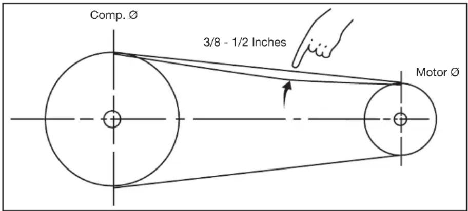
Note: Do not over tighten bolts.
Note: Electric Motor-grease once a year with a good grade of lithium ball bearing grease, or as directed by the motor manufacturer.
- Remove any moisture in the air compressor air tank. NEVER attempt to open the Air Tank Drain Valve when more than 10 PSI is in the air tank! Remove excessive pressure with an air tool, then open the Air Tank Drain Valve in the bottom of the air tank. Close tightly when drained.
- Make sure the Motor/Pressure Switch is in the "OFF" position.
- Make sure the Safety Relief Valve is working correctly.
- Make sure all guards and covers are in place and securely mounted.

WARNING RISK OF BODILY INJURY! NEVER ATTEMPT TO OPEN THE AIR TANK DRAIN VALVE WHEN MORE THAN 10 PSI OF AIR PRESSURE IS IN THE AIR TANK!
OPERATING INSTRUCTIONS
START-UP:
- Read safety warnings before performing operation.
- a.) Move the Motor/Pressure Switch to the "AUTO" position.
b.) Rotate the Cam Switch counter-clockwise to the Auto Start/Stop position. - If you notice any unusual noise or vibration, stop the air compressor and refer to "Troubleshooting".
SHUTDOWN:
- To stop the air compressor,
a.) Move the Motor/Pressure Switch to the "OFF" position or
b.) Rotate the Cam Switch to the center "OFF" position. - Drain air from the air tanks by releasing air with an attached air tool or by pulling on the Safety Relief Valve.
- Once the Air Tank Pressure Gauge registers under 10 PSI, open the Air Tank Drain Valve under the air tank to drain any moisture.
- Allow the air compressor to cool down, then wipe clean.
MAINTENANCE INSTRUCTIONS
Read the instruction manual before performing maintenance. The following procedures must be performed when stopping the air compressor for maintenance or service.
- Turn off air compressor.
- Open all drains after the tank gauge registers under 10 PSI.
- Wait for the air compressor to cool before starting service.

WARNING RISK OF BODILY INJURY!
NEVER ASSUME THE AIR COMPRESSOR IS SAFE TO WORK ON JUST BECAUSE IT IS NOT OPERATING. IT COULD RESTART AT ANY TIME!
| AC Ele. Maintenance Chart | ||||
| MAINTENANCE CHART | ||||
| PROCEDURE DAILY WEEK | KLY MONTHLY | 1000 HOURS | ||
| Check pump oil level X | ||||
| Oil leak inspection X | ||||
| Drain condensation in air tank (s) X | ||||
| Inspect guards/covers X | ||||
| Check for unusual noise/vibration | X | |||
| Check for air leaks | X | |||
| Clean exterior of compressor | X | |||
| Inspect air filter | X | |||
| Inspect belt | X | |||
| Check safety relief valve | X | |||
| Change pump oil * | X | |||
| Replace air filter | X | |||
*THE PUMP OIL MUST BE CHANGED AFTER THE FIRST 100 HOURS OF OPERATION AND EVERY 1000 HOURS OR 3 MONTHS, WHICHEVER COMES FIRST. EVERY TWO YEARS, AN AUTHORIZED SERVICE TECHNICIAN SHOULD CHECK THE CHECK VALVE, INTAKE VALVES AND DELIVERY VALVES.
| SYMPTOM | TROUBLESHOOTING | |
| PROBABLE CAUSE | REMEDY | |
| Air compressor will not start. | Motor/Pressure Switch turned "OFF". | Move Motor/Pressure Switch to "AUTO" position. |
| Motor Thermal Overload tripped on air compressor. | Turn unit off, wait 5 minutes, then press Motor Thermal Overload until click is heard. | |
| Circuit breaker tripped or fuse blown at power source. | Reset circuit breaker or replace fuse if necessary, using only "Fusetron" type T fuses. | |
| Check for low voltage conditions. | ||
| Disconnect any other electrical appliances from circuit or operate air compressor on its own branch circuit. | ||
| Motor voltage does not match power source. | Contact your Customer Service. | |
| Air tank pressure achieved the "Maximum setting" or "Stop pressure" of the Motor/Pressure Switch. | The motor will start automatically when air tank pressure drops down to the "Cut-in" or "Start" pressure of the Motor/Pressure Switch. | |
| Pressure release valve on Motor/Pressure Switch has not unloaded pump head pressure. | Bleed the line by moving the switch to the "Off" position. | |
| Pilot valve's check valve stuck open. | Remove and clean or replace. | |
| Defective motor, or Motor/Pressure Switch. | Contact your Customer Service. | |
| Low oil level (if unit is equipped with Low Oil Sensor) | Add oil to pump | |
| Air compressor will not start, but motor hums, then stops. | Loose electrical connection. | Contact qualified electrician. |
| Too many appliances being operated on same circuit. | Use another circuit or remove excess appliances from circuit. | |
| Incorrect voltage, incorrect sized circuit breaker, fuse or motor. | Contact qualified electrician. | |
| Defective motor. | ||
| Defective Check Valve or Motor/Pressure Switch. | Replace. | |
| Air compressor does not stop even though the maximum pressure allowed has been reached. | Motor/Pressure Switch not operating correctly. | Replace |
| Noisy operation. | Loose motor pulley or pump flywheel.Lack of oil in the pump.Carbon deposits on pistons or valves.Bearing, piston or connecting rod failure. | Tighten pulley and or flywheel.Add correct amount of oil.Remove cylinder head and inspect. Clean or replace valve plate.STOP THE AIR COMPRESSOR! Contact Mi-T-M® Customer Service. |
| Pressure drop in air tank or rapid pressure loss when air compressor is shut off. | Air leaks at connections.Defective Check Valve or Pilot Valve.Air leak in air tank. | Allow the air compressor to build pressure to the maximum allowed. Turn off and brush a soapy water solution onto all connections. Check connections for air bubbles. Tighten the connections where leaks are present.Remove, clean or replace.Air tank must be replaced. Do not attempt to repair air tank! |
| Insufficient pressure at air tool or accessory. | Air leaks or restrictions.Restricted air intake filter.Pipe, hose or hose connections are too small or long.Air compressor is not large enough for air requirement.Slipping belt.Restricted Pilot Valve. | Check for leaks and repair.Clean or replace.Replace with larger pipe, hose or connectors.Use a smaller tool or larger air compressor.Tighten or replace.Clean or replace. |
| Air leaks from Safety Relief Valve. | Possible defective Safety Relief Valve.Excessive air tank pressure. | Operate Safety Relief Valve manually by pulling on ring. If it still leaks, it should be replaced.Replace Motor/Pressure Switch. Clean, reset or replace Pilot Valve. |
| Air leaks at pump. | Defective gaskets. | Torque head bolts to 19.5 ft./lbs. for Single Stage & 33.2 for 2 stage. |
| Air continues to leak at Motor/Pressure Switch while motor is running. | Defective Motor/Pressure Switch. | Replace. |
| Air blowing from Air Intake Filter during Normal mode operation (not Continuous Run). | Damaged inlet (reed) valve. | Remove cylinder head and inspect. Clean or replace valve plate. |
| SYMPTOM | TROUBLESHOOTING PROBABLE CAUSE | REMEDY |
| When in the Start/Stop Option, motor runs continuously. | Motor/Pressure Switch does not shut off motor when air compressor reaches "cut-out" pressure and safety relief valve activates. | Move the Motor/Pressure Switch to the "OFF" position. If the motor does not shut off, remove power to the machine. If the electrical contacts are welded together, replace the pressure switch. |
| Air compressor is incorrectly sized. | Limit the air usage to the capacity of the air compressor. Either use a smaller tool or a larger air compressor. | |
| Moisture in discharge air. | Condensation in air tank caused by high level of atmospheric humidity. | Drain air tank after every use.Drain air tank more often in humid weather and use an air line filter. |
| Excessive oil consumption or oil in hose. | Restricted air intake filter.Air compressor on unlevel surface.Crankcase overfilled with oil.Wrong viscosity.Plugged oil dipstick vent.Oil leaks.Worn piston rings or scored cylinder. | Clean or replace.Do not incline the air compressor more than 10^ in any direction while running.Drain oil. Refill to proper level with SAE-30W non-detergent oil.Drain oil. Refill to proper level with SAE-30W non-detergent oil.Clean.Tighten pump bolts to torque stated in Parts List, or replace gaskets.Contact Mi-T-M® Customer Service. |
| Oil has milky appearance. | Water in oil due to condensation. | Drain oil. Refill to proper level with SAE-30W non-detergent oil. |
| Unit runs backward. | Reversed wiring. | Contact qualified electrician. |
STATEMENT OF WARRANTY
Mi-T-M® warrants all parts, (except those referred to below), of your new air compressor to be free from defects in materials and workmanship during the following periods:
For Two (2) Years from the date of original purchase:
Plumbing Tank Assembly
For Five (5) Years from the date of original purchase. 1st Three (3) years at 100%, the Forth (4th) year at 90% and the Fifth (5th) year at 80%.
Compressor Pump
For Six (6) Months from the date of original purchase:
Pressure Switch Regulator
Check Valve Pilot Valve
Copper/Stainless Steel Line
For Ninety (90) days from the date of original purchase:
Pressure Gauges
Safety Relief Valves
Drain Valves
Defective parts not subject to normal wear and tear will be repaired or replaced at our option during the warranty period. In any event, reimbursement is limited to the purchase price paid.
EXCLUSIONS
- Motor is covered under separate warranty by its respective manufacturer and is subject to the terms set forth therein.
- Normal wear parts:
Air Filter Isolators
- This warranty does not cover parts damaged due to normal wear, abnormal conditions, misapplication, misuse, accidents, operation at other than recommended voltage, pressures or temperature, improper storage or freight damage. Parts damaged or worn by operation in dusty environments are not warranted. Failure to follow recommended operating and maintenance procedures also voids warranty.
- Labor charges, loss or damage resulting from improper operation, maintenance (other than routine air tank draining and oil changes, if applicable) or repairs made by persons other than a Mi-T-M® Authorized Service Center.
- The use of other than Genuine Mi-T-M® Repair Parts will void warranty. Parts returned, prepaid to our factory or to an Authorized Service Center will be inspected and replaced free of charge if found to be defective and subject to warranty. Under no circumstances shall the manufacturer bear any responsibility for loss of use of the unit, loss of time or rental, inconvenience, commercial loss or consequential damages. There are no warranties which extend beyond the description of the face hereof.
For Service or Warranty Consideration, contact
Mi-T-M® Corporation, 50 Mi-T-M Drive, Peosta, IA 52068
563-556-7484 / 800-553-9053 / Fax 563-556-1235
Monday - Friday 8:00 a.m. - 5:00 p.m. CST
CONTENTS
INTRODUCTION 26
INSTRUCTIONS IMPORTANTES DE SÉCURITÉ....27
CARACTERISTIQUES DU COMPRESSEUR D'AIR....31
CARACTERISTIQUES DE LA POMPE/MOTEUR....31
APPAREILS DISPONIBLES EN RESERVOIR HORIZONTAL, VERTICAL ET
EN BLOC A EMBASE 31
CARACTERISTIQUES DU MOTEUR ....31
COMPOSANTS DU COMPRESSEUR D'AIR ELECTRIQUE....32
COMPRESSEUR VERTICAL INDUSTRIEL DE 80 GALLONS A 2 ETAGES....32
COMPOSANTS DU COMPRESSEUR D'AIR ELECTRIQUE....33
COMPRESSEUR HORIZONTAL INDUSTRIEL DE 80 GALLONS A 2 ETAGES ....33
VUE DETAILLEE ET EXPLICATION DES COMPOSANTS DU COMPRESSEUR 34
INSTRUCTIONS DE PREPARATION....37
INSTALLATION INITIALE: 37
EMPLACEMENT: 37
PREPARATION INSTRUCTIONS....38
ELECTRIQUE....38
POINTS DE CONTROLE AVANT DEMARRAGE: 38
INSTRUCTIONS DE FONCTIONNEMENT....39
DEMARRAGE: 40
ARRET: 40
INSTRUCTIONS D'ENTRETIEN....41
DEPANNAGE 42
BON DE GARANTIE....45
EXCLUSIONS 45
▲ AVERTISSEMENT
Hazard Potential Consequence Prevention
RISQUE DE DÉCHARGE ÉLECTRIQUE OU D'ÉLECTROCUTION
natural_image
Black silhouette of a hand with a lightning bolt symbol indicating electrical hazard (no text or labels)natural_image
Technical line drawing of a mechanical clamp or bracket assembly (no text or symbols)natural_image
Technical line drawing of a mechanical housing or enclosure with mounting holes and internal components (no text or symbols)natural_image
Technical line drawing of a mechanical assembly with no visible text or symbolsnatural_image
Technical line drawing of a mechanical assembly with no visible text or symbolsPREPARATION INSTRUCTIONS
ELECTRIQUE
POINTS DE CONTROLE AVANT DEMARRAGE:
flowchart
graph TD
    A["Proper Oil Level"] --> B["Oil Gauge"]
    B --> C["Water Supply"]

ATTENTION: LE FAIT DE TROP SERRER LA/LES COURROIE(S) TRAPEZOÏDALE(S) VA ENTRAINER UNE SURCHARGE DU MOTEUR ET UNE DEFAILLANCE DE LA COURROIE. UNE COURROIE DESSERREE VA GLISSER ET RESULTER EN UNE VITESSE INSTABLE, UNE SURCHAUFFE DE LA COURROIE ET UN DEBIT EN AMPERES ELEVE.
| AC Ele. Maintenance Chart | ||||
| MAINTENANCE CHART | ||||
| PROCEDURE DAILY WEEKLY MONTHLY 1000 HOUR | ||||
| Check pump oil level X | ||||
| Oil leak inspection X | ||||
| Drain condensation in air tank (s) X | ||||
| Inspect guards/covers X | ||||
| Check for unusual noise/vibration X | ||||
| Check for air leaks | X | |||
| Clean exterior of compressor | X | |||
| Inspect air filter | X | |||
| Inspect belt | X | |||
| Check safety relief valve | X | |||
| Change pump oil * | X | |||
| Replace air filter | X | |||
*L'HUILE DE POMPE DOIT ÊTRE CHANGÉE APRÉS LES PREMIÈRES 100 HEURES D'OPÉRATION ET TOUTES LES 1000 HEURES OU 3 MOIS, SELON LA LIMITE QUI EST ATTEINTE EN PREMIER. TOUS LES 2 ANS, UN TECHNICIEN DE SERVICE AUTORISÉ DOIT VÉRIFIER LA SOUPAPE DE RETENUE, LES SOUPAPES D'APPROVISIONNEMENT ET LES SOUPAPES DE DISTRIBUTION.
Hazard Potential Consequence Prevention
natural_image
Black silhouette of a hand with a lightning bolt and lightning symbol, representing electrical hazard (no text or labels)Hazard Potential Consequence Prevention
natural_image
Symbolic icon of a hand holding a camera with red graphical elements (no text or symbols)RIESGO DE PARTES EN MOVIMIENTO
natural_image
Technical line drawing of a mechanical clamp or bracket assembly (no text or symbols)natural_image
Technical line drawing of a mechanical housing or enclosure with mounting holes and internal components (no text or symbols)natural_image
Technical line drawing of a mechanical assembly with no visible text or symbolsnatural_image
Pure mechanical diagram showing a cylindrical component mounted on a base with a connecting rod (no text or symbols)CONTROLES ANTES DEL ARRANQUE:

AC Ele. Maintenance Chart Spanish
Lunes - Viernes 8:00 a.m. - 5:00 p.m. CST
Manufactured by Mi-T-M 50 Mi-T-M Drive, Peosta IA 52068 563-556-7484/ Fax 563-556-1235
- GALLON INDUSTRIAL AIR COMPRESSOR
- OPERATOR'S MANUAL
- CONTENTS
- ⚠ WARNING
- INTRODUCTION
- IMPORTANT!
- SERIAL NUMBER
- IMPORTANT SAFETY INSTRUCTIONS
- Hazard Potential Consequence Prevention
- RISK OF ELECTRIC SHOCK OR ELECTROCUTION
- ! SAVE THESE INSTRUCTIONS !
- AIR COMPRESSOR FEATURES
- GALLON VERTICAL COMPRESSOR 2 STAGE INDUSTRIAL
- GALLON HORIZONTAL COMPRESSOR 2 STAGE INDUSTRIAL
- EXPLODED VIEW & EXPLANATION OF AIR COMPRESSOR FEATURES
- WARNING
- THE FOLLOWING PAGES CONTAIN OPERATING AND MAINTENANCE INSTRUCTIONS.
- DO NOT ATTEMPT TO OPERATE THIS AIR COMPRESSOR UNTIL YOU HAVE READ AND UNDERSTOOD ALL SAFETY PRECAUTIONS AND INSTRUCTIONS LISTED IN THIS MANUAL.
- PREPARATION INSTRUCTIONS
- INITIAL SET-UP:
- WARNING RISK OF EXPLOSION OR FIRE CAUSING SERIOUS INJURY OR DEATH!
- LOCATION:
- ELECTRICAL
- DANGER RISK OF ELECTROCUTION!
- WARNING RISK OF ELECTRICAL SHOCK!
- PRE-START CHECKLIST:
- OPERATING INSTRUCTIONS
- START-UP:
- SHUTDOWN:
- MAINTENANCE INSTRUCTIONS
- WARNING RISK OF BODILY INJURY!
- NEVER ASSUME THE AIR COMPRESSOR IS SAFE TO WORK ON JUST BECAUSE IT IS NOT OPERATING. IT COULD RESTART AT ANY TIME!
- STATEMENT OF WARRANTY
- EXCLUSIONS
- ▲ AVERTISSEMENT
- RISQUE DE DÉCHARGE ÉLECTRIQUE OU D'ÉLECTROCUTION
- ELECTRIQUE
- POINTS DE CONTROLE AVANT DEMARRAGE:
- RIESGO DE PARTES EN MOVIMIENTO
- CONTROLES ANTES DEL ARRANQUE:
Brand : Mi-T-M
Model : ACS-23105-80H
Category : Compressor