
AM1-PE15-20M - Compressor Mi-T-M - Free user manual and instructions
Find the device manual for free AM1-PE15-20M Mi-T-M in PDF.

| Brand | Mi-T-M |
| Model | AM1-PE15-20M |
| Product Type | Electric Air Compressor |
| Tank Capacity | 8 gallons (approx. 30 liters) |
| Power Supply | Grounded electrical outlet (120V/240V depending on model) |
| Motor | With manual thermal protection |
| Pump Type | Single-stage compressor (reference AC1-PE15) |
| Lubrication | Non-detergent SAE30 oil, level visible via indicator |
| Maximum Pressure | Factory set (see manual) |
| Pressure Regulation | Pressure regulator with outlet pressure gauge |
| Safety Valve | Yes, manually operated for verification |
| Moisture Drain | Drain valve at tank bottom (open under 10 PSI) |
| Air Filter | Washable intake filter with soapy water |
| Routine Maintenance | Daily tank drain, oil check, filter cleaning |
| Oil Change | Every 200 hours (first at 50 hours) |
| Safety | Motor/pressure switch, grounding, thermal protection |
| Spare Parts | Available from Mi-T-M (see contact in manual) |
| Warranty | 2 years on pump and tank, 6 months on electrical components |
| Manual | 60 pages, including safety instructions, operation, and troubleshooting |
Frequently Asked Questions - AM1-PE15-20M Mi-T-M
User questions about AM1-PE15-20M Mi-T-M
0 question about this device. Answer the ones you know or ask your own.
Ask a new question about this device
Download the instructions for your Compressor in PDF format for free! Find your manual AM1-PE15-20M - Mi-T-M and take your electronic device back in hand. On this page are published all the documents necessary for the use of your device. AM1-PE15-20M by Mi-T-M.
USER MANUAL AM1-PE15-20M Mi-T-M
natural_image
Abstract geometric logo design resembling the letter 'M' in grayscale, no text or symbols present.Mi-T-M®
CORPORATION
PORTABLE ELECTRIC AIR COMPRESSOR
OPERATOR'S MANUAL
PARTS LIST


CAUTION
RISK OF INJURY! READ ENTIRE MANUAL BEFORE OPERATING!
THIS MANUAL IS AN IMPORTANT PART OF THE AIR COMPRESSOR
AND MUST REMAIN WITH THIS UNIT!
TABLE OF CONTENTS
INTRODUCTION....3
IMPORTANT 3
INSPECTION 3
IMPORTANT SAFETY INSTRUCTIONS....4-7
RISK OF ELECTRIC SHOCK OR ELECTROCUTION 4
RISK OF EXPLOSION OR FIRE 5
RISK OF BURSTING....5
RISK TO BREATHING 6
RISK OF BURNS 6
RISK OF FLYING OBJECTS 6
RISK FROM MOVING PARTS....7
RISK FROM NEGLIGENCE....7
RISK OF AIR COMPRESSOR DAMAGE 7
FEATURES DRAWINGS....8 & 10
FEATURES REVIEW....9 & 11
PREPARATION INSTRUCTIONS....13
INITIAL SET-UP 13
LOCATION....13
ELECTRICAL....13
PRE-START CHECKLIST....13
OPERATING INSTRUCTIONS....14
START-UP 14
SHUTDOWN....14
MAINTENANCE INSTRUCTIONS....15
TROUBLESHOOTING....16-18
WARRANTY....19
NOTES....20-21

Intertek
3012903

Intertek
3012903
8 Gallon models
20 Gallon models
▲ WARNING
⚠ WARNING: This product can expose you to chemicals including Lead, which is known to the State of California to cause cancer and birth defects or other reproductive harm. For more information go to www.P65Warnings.ca.gov
INTRODUCTION
Congratulations on the purchase of your new Mi-T-M® Air Compressor! You can be assured your Mi-T-M® Air Compressor was constructed with the highest level of precision and accuracy. Each component has been rigorously tested by technicians to ensure the quality, endurance and performance of this air compressor.
This operator's manual was compiled for your benefit. By reading and following the simple safety, installation and operation, maintenance and troubleshooting steps described in this manual, you will receive years of trouble free operation from your new Mi-T-M® Air Compressor. The contents of this manual are based on the latest product information available at the time of publication. Mi-T-M® reserves the right to make changes in price, color, materials equipment, specifications or models at any time without notice.

IMPORTANT!
A "DANGER, WARNING or CAUTION" safety warning will be surrounded by a "SAFETY ALERT BOX". This box is used to designate and emphasize Safety Warnings that must be followed when operating this air compressor. Accompanying the safety warnings are "Signal Words" which designate the degree or level of hazard seriousness. The "Signal Words" used in this manual are as follows:
DANGER: Indicates an imminently hazardous situation which, if not avoided, WILL result in death or serious injury.
WARNING: Indicates a potentially hazardous situation which, if not avoided, COULD result in death or serious injury.
CAUTION: Indicates a potentially hazardous situation which, if not avoided MAY result in minor or moderate injury or damage to the air compressor.
The symbols set to the left of this paragraph are "Safety Alert Symbols". These symbols are used to call attention to items or procedures that could be dangerous to you or other persons using this equipment.
ALWAYS PROVIDE A COPY OF THIS MANUAL TO ANYONE USING THIS EQUIPMENT. READ ALL INSTRUCTIONS IN THIS MANUAL AND ANY INSTRUCTIONS SUPPLIED BY MANUFACTURERS OF SUPPORTING EQUIPMENT BEFORE OPERATING THIS AIR COMPRESSOR AND ESPECIALLY POINT OUT THE "SAFETY WARNINGS" TO PREVENT THE POSSIBILITY OF PERSONAL INJURY TO THE OPERATOR.
Once the unit has been uncrated, immediately write in the serial number of your unit in the space provided below.
SERIAL NUMBER
Inspect for signs of obvious or concealed freight damage. If damage does exist, file a claim with the transportation company immediately. Be sure that all damaged parts are replaced an that the mechanical and electrical problems are corrected prior to operation of the unit. If you require service, contact Mi-T-M® Customer Service.
Mi-T-M® Corporation, 50 MI-T-M Drive, Peosta, IA 52068
1-563-556-7484 / (1-800-553-9053 / Fax 563-556-1235
Monday - Friday 8:00 a.m. - 5:00 p.m. CST
Please have the following information available for all service calls:
-
Model Number
-
Serial Number
-
Date and Place of Purchase
| HAZARD | POTENTIAL CONSEQUENCE | PREVENTION |
RISK OF ELECTRIC SHOCK OR ELECTROCUTION | Serious injury or death could occur if the air compressor is not properly grounded. Your air compressor is powered by electricity and may cause electric shock or electrocution if not used properly.Electrical shock may occur from electrical cord.Electrical shock may occur if air compressor is not operated properly.Serious injury or death may occur if electrical repairs are attempted by unqualified persons. | Make sure the air compressor is plugged into a properly grounded outlet which provides correct voltage and adequate fuse protection. Disconnect when not in use.Check power cord for signs of crushing, cutting or heat damage. Replace faulty cord before use.Keep all connections dry and off the ground. Do not allow electrical cords to lay in water or in such a position where water could come in contact with them. Do not touch plug with wet hands.Do not pull on the electrical cord to disconnect from the outlet.Never operate air compressor in wet conditions or outdoors when it is raining.Never operate air compressor with safety guards/covers removed or damaged.Any electrical wiring or repairs performed on this air compressor should be done by Authorized Service Personnel in accordance with National and Local electrical codes.Before opening any electrical enclosure, always shut off the air compressor, relieve pressure and unplug the air compressor from the power source. Allow air compressor to cool down. Never assume the air compressor is safe to work on just because it is not operating. It could restart at any time! Service in a clean, dry, flat area. |
RISK OF EXPLOSION OR FIRE | Serious injury or death may occur from normal electrical sparks in motor and pressure switch | Always operate air compressor in a well ventilated area free of flammable vapors, combustible dust, gases or other combustible materials.DO NOT SMOKE if spraying flammable material. Locate the air compressor at least 20 feet away from the spray area. (An additional hose may be required.) |
 | Serious injury may occur if any air compressor ventilation openings are restricted, causing the air compressor to overheat and start a fire. | Never place objects against or on top of air compressor. Operate air compressor at least 12 inches away from any wall or obstruction that would restrict proper ventilation. |
RISK OF BURSTING | Serious injury or death may occur from an air tank explosion if air tanks are not properly maintained.Serious injury may occur from an air compressor malfunction or exploding accessories if incorrect system components, attachments or accessories are used. | Drain air tank daily or after each use to prevent moisture buildup in the air tank.If air tank develops a leak, replace the air tank immediately. Never repair, weld or make modifications to the air tank or its attachments. Use only genuine Manufacturer repair parts for your air compressor.Never make adjustments to the factory set pressures.Never exceed manufacturers maximum allowable pressure rating of attachments.Because of extreme heat, do not use plastic pipe or lead tin soldered joints for a discharge line.Never use air compressor to inflate small, low pressure objects such as toys. |

READ ALL SAFETY INSTRUCTIONS BEFORE USING AIR COMPRESSOR
IMPORTANT SAFETY INSTRUCTIONS

| POTENTIAL CONSEQUENCE | PREVENTION | |
RISK TO BREATHING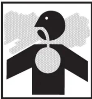 | Serious injury or death could occur from inhaling compressed air. The air stream may contain carbon monoxide, toxic vapors or solid particles.Sprayed materials such as paint, paint solvents, paint remover, insecticides, weed killers, etc. contain harmful vapors and poisons. | Never inhale air from the air compressor either directly or from a breathing device connected to the air compressor.Operate air compressor only in a well ventilated area. Follow all safety instructions provided with the materials you are spraying. Use of a respirator may be required when working with some materials. |
RISK OF BURNS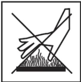 | Serious injury could occur from touching exposed metal parts. These areas can remain hot for some time after the air compressor is shutdown. | Never allow any part of your body or other materials to make contact with any exposed metal parts on the air compressor. |
RISK OF FLYING OBJECTS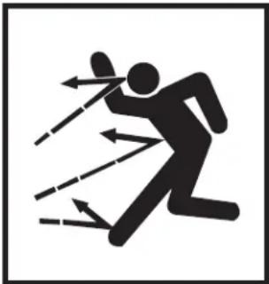 | Soft tissue damage can occur from the compressed air stream.Serious injury can occur from loose debris being propelled at a high speed from the compressed air stream. | Always wear safety glasses to shield the eyes from flying debris.Never point the air stream at any part of your body, anyone else or animals.Never leave pressurized air in the air compressor. Shut off air compressor and relieve pressure when storing or attempting maintenance.Always maintain a safe distance from people and animals while operating the air compressor.Do not move the air compressor while air tank is under pressure. Do not attempt to move the air compressor by pulling on the hose. |

IMPORTANT SAFETY INSTRUCTIONS
READ ALL SAFETY INSTRUCTIONS BEFORE USING AIR COMPRESSOR

| HAZARD | POTENTIAL CONSEQUENCE | PREVENTION |
RISK FROM MOVING PARTS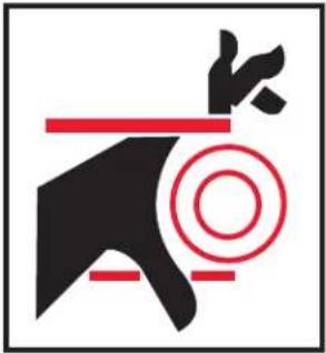 | Risk of bodily injury from moving parts. This air compressor cycles automatically when the pressure switch is in the "On/Auto" position. | Before performing maintenance, always turn off air compressor.Bleed pressure from the air hose and unplug electrical cord from outlet. All repairs to the air compressor should be made by an Authorized Service person. Never assume the air compressor is safe to work on just because it is not operating. It could restart at any time!Do not operate without protective covers/guards. Always unplug the air compressor before removing any guard. Replace damaged covers/guards before using the air compressor. |
| RISK FROM NEGLIGENCE | Risk of injury from negligent use. | Never allow children or adolescents to operate this air compressor!Stay alert-watch what you are doing. Do not operate the air compressor when fatigued or under the influence of alcohol or drugs.Know how to stop the air compressor. Be thoroughly familiar with controls. |
| RISK OF AIR COMPRESSOR DAMAGE | Risk of major repair. | Do not operate air compressor without an air filter.Do not operate air compressor in a corrosive environment.Always operate the air compressor in a stable, secure position to prevent air compressor from falling.Follow all maintenance instructions listed in this manual. |

! SAVE THESE INSTRUCTIONS !
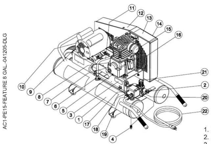
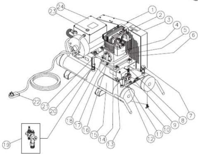
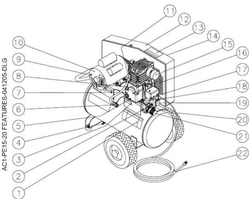
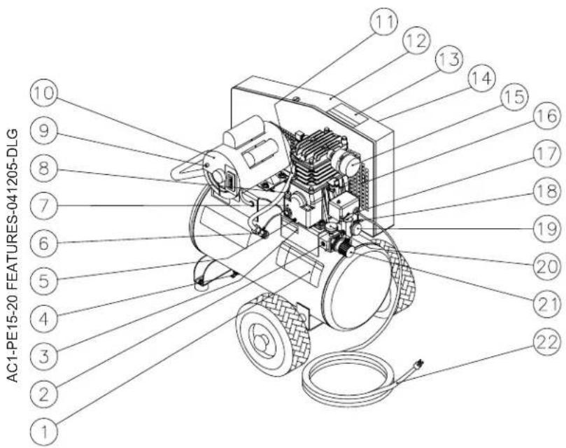
ELECTRIC AIR COMPRESSOR FEATURES (SINGLE STAGE)
- Decal- Danger/Warning/Caution
- Outlet Fitting
- Decal- Warning: Hot Surface
- Tank Drain Valve
- Pump Oil Drain
- Check Valve
- Air Compressor Pump
- Pump Oil Fill Port
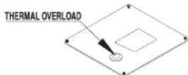
- Thermal Overload
- Electric Motor
- Pump Discharge Line
- Beltguard
- Decal- Warning: Risk of Injury
- Decal- Warning: Beltguard in Place
- Air Filter
- Ventilation Holes
- Pressure Switch
- Pressure Relief Valve
- Pressure Gauge- Tank PSI
- Pressure Gauge- Outlet PSI
- Pressure Regulator
- Electric Power Cord
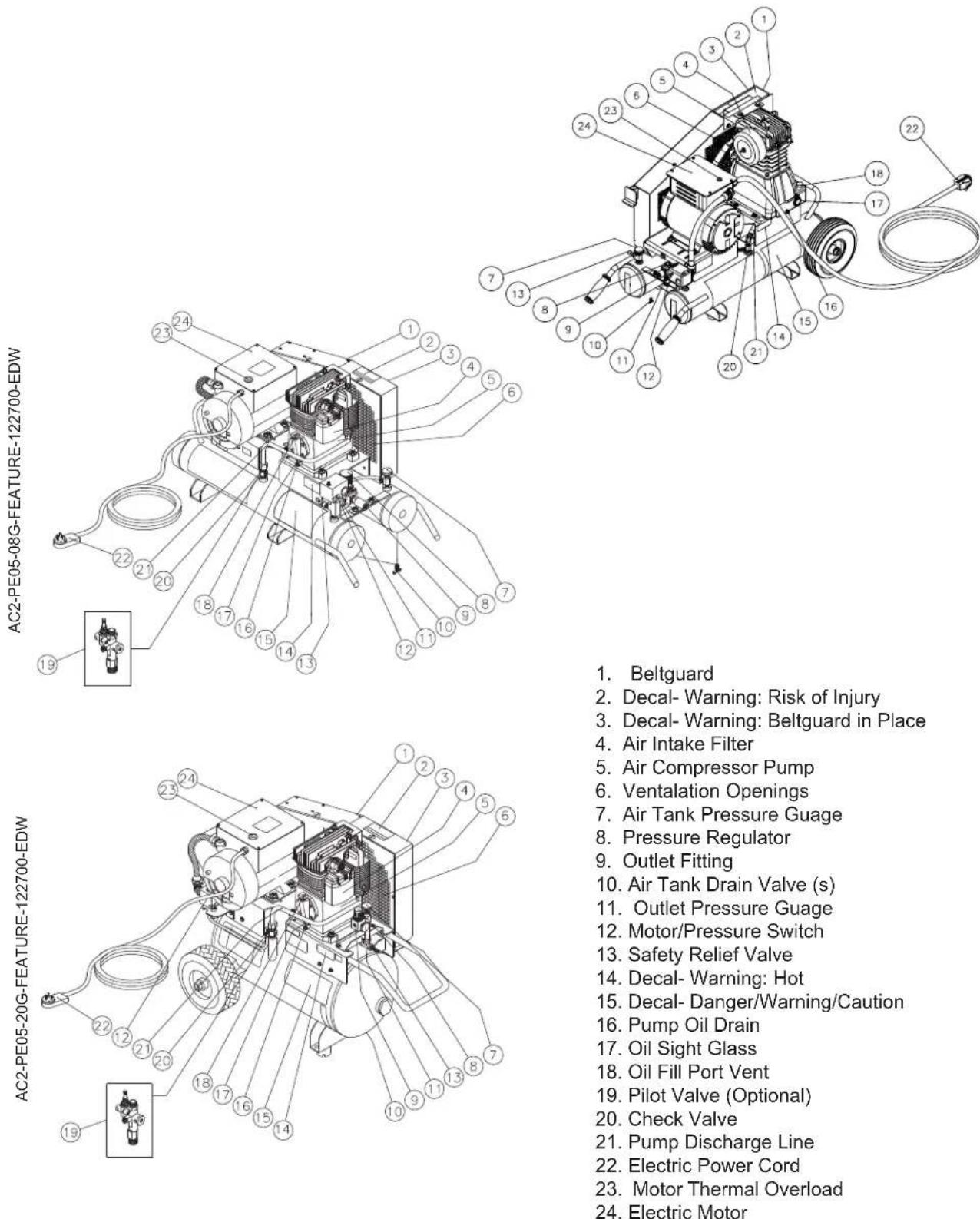
EXPLODED VIEW & EXPLANATION OF AIR COMPRESSOR FEATURES
natural_image
Exploded view diagram of a mechanical component showing four views (top, front, side, and top) with no text or symbols.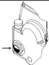
SAFETY RELIEF VALVE: This valve is designed to prevent system failures by relieving pressure from the system when the compressed air reaches a predetermined level. The valve is preset by the manufacturer and must not be modified in any way. To verify the valve is working properly, pull on the ring. Air pressure should escape. When the ring is released, it will reset.
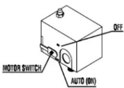
MOTOR/PRESSURE SWITCH: This switch is used to start or stop the air compressor. Moving the switch to the "Auto" (On) position will provide automatic power to the pressure switch which will allow the motor to start when the air tank pressure is below the factory set "cut-in" pressure. When in the Start/Stop Option, the pressure switch stops the motor when the air tank pressure reaches the factory set "cut-out" pressure. For safety purposes, this switch also has a pressure release valve located on the side of the switch designed to automatically release compressed air from the air compressor pump head and its discharge line when the air compressor reaches "cut-out" pressure or is shut off. This allows the motor to restart freely. Moving the switch to the "Off" position will remove power from the pressure switch and stop the air compressor.
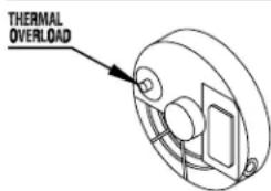
MOTOR THERMAL OVERLOAD: The electric motor has a manual thermal overload protector. If the motor overheats for any reason, the thermal overload will cut off power, thus preventing the motor from being damaged. Wait until the motor is cool before pressing the thermal overload button to reset and begin working again.
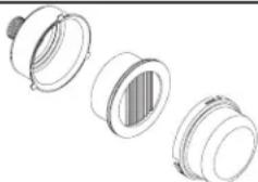
AIR INTAKE FILTER: This filter is designed to clean air coming into the pump. To ensure the pump continually receives a clean, cool, dry air supply this filter must always be clean and ventilation opening free from obstructions. Replace filter element when necessary.
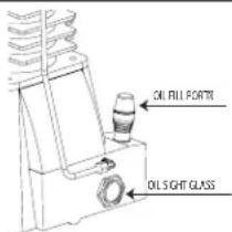
OIL FILL PORT/VENT: Pour oil into the Oil Fill Port/Vent when required.
OIL SIGHT GLASS: The Oil Sight Glass displays the oil level in the pump. The oil level should be at the center of the Oil Sight Glass. If low, add SAE 30W non-detergent oil.
AIR COMPRESSOR PUMP: To compress air, the pistons move up and down in the cylinders. On the downstroke, air is drawn in through the air intake valves while the exhaust valves remain closed. On the upstroke, air is compressed, the intake valves close and compressed air is forced out through the exhaust valves, into the discharge line, through the check valve and/or the pilot valve and into the air tank.
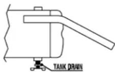
AIR TANK DRAIN VALVE: The drain valve is used to remove moisture from the air tank(s) after the air compressor is shut off. NEVER attempt to open the drain valve when more than 10 PSI of air pressure is in the air tank! To open the drain valve, turn the knob counterclockwise.
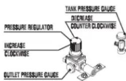
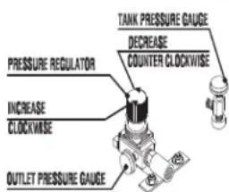
AIR TANK PRESSURE GAUGE: The air tank pressure gauge indicates the reserve air pressure in the air tank (s).
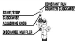
PRESSURE REGULATOR: The air pressure coming from the air tank is controlled by the regulator knob. Turn the pressure regulation knob clockwise to increase discharge pressure, and counterclockwise to decrease discharge pressure.
OUTLET PRESSURE GAUGE: The outlet pressure gauge indicates the air pressure available at the outlet side of the regulator. This pressure is controlled by the regulator and is always less or equal to the air tank pressure.
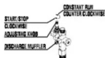
OPTION PILOT VALVE: When the adjusting knob is turned completely clockwise to the fully closed position, the air compressor operates in the Start/Stop position. When the adjusting knob is turned completely counterclockwise to the fully open position, the air compressor operates in the constant run position.
ELECTRIC AIR COMPRESSOR FEATURES
(TWO STAGE)
AS2-PE05-08 FEATURES-122704-DLG
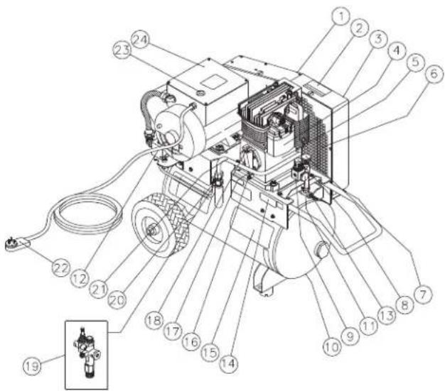
-
Beltguard
-
Decal- Warning: Risk of Injury
-
Decal- Warning: Beltguard in Place
-
Air Intake Filter
-
Air Compressor Pump
-
Ventalation Openings
-
Air Tank Pressure Guage
-
Pressure Regulator
-
Outlet Fitting
-
Air Tank Drain Valve (s)
-
Outlet Pressure Guage
-
Motor/Pressure Switch
-
Safety Relief Valve
-
Decal- Warning: Hot
-
Decal- Danger/Warning/Caution
-
Pump Oil Drain
-
Oil Sight Glass
-
Oil Fill Port Vent
-
Pilot Valve (Optional)
-
Check Valve
-
Pump Discharge Line
-
Electric Power Cord
-
Motor Thermal Overload
-
Electric Motor
EXPLODED VIEW & EXPLANATION OF AIR COMPRESSOR FEATURES
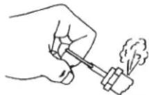
SAFETY RELIEF VALVE: This valve is designed to prevent system failures by relieving pressure from the system when the compressed air reaches a predetermined level. The valve is preset by the manufacturer and must not be modified in any way. To verify the valve is working properly, pull on the ring. Air pressure should escape. When the ring is released, it will reset.
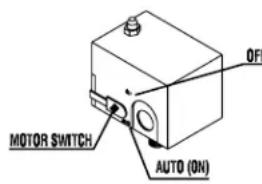
MOTOR/PRESSURE SWITCH: This switch is used to start or stop the air compressor. Moving the switch to the "Auto" (On) position will provide automatic power to the pressure switch which will allow the motor to start when the air tank pressure is below the factory set "cut-in" pressure. When in the Start/Stop Option, the pressure switch stops the motor when the air tank pressure reaches the factor set "cut-out" pressure. For safety purposes, this switch also has a pressure release valve located on the side of the switch designed to automatically release compressed air from the air compressor pump head and its discharge line when the air compressor reaches "cut-out" pressure or is shut off. This allows the motor to restart freely. Moving the switch to the "Off" position will remove power from the pressure switch and stop the air compressor.
MOTOR THERMAL OVERLOAD: The electric motor has a manual thermal overload protector. If the motor overheats for any reason, the thermal overload will cut off power, thus preventing the motor from being damaged. Wait until the motor is cool before pressing the thermal overload button to reset and begin working again.
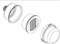
AIR INTAKE FILTER: This filter is designed to clean air coming into the pump. To ensure the pump continually receives a clean, cool, dry air supply this filter must always be clean and ventilation opening free from obstructions. Replace filter element when necessary.
OIL FILL PORT/VENT: Pour oil into the Oil Fill Port/Vent when required.
OIL SIGHT GLASS: The Oil Sight Glass displays the oil level in the pump. The oil level should be at the center of the Oil Sight Glass. If low, add SAE 30W non-detergent oil.
AIR COMPRESSOR PUMP: A two stage compressor pump uses two different size cylinders with the intake valve of the second smaller cylinder linked to the exhaust valve of the first larger cylinder. On the down stroke of the large cylinder, air is drawn through the intake valve while the exhaust valve remains closed. On the upstroke, air is compressed, the intake valve closes and compressed air is forced out through the exhaust valve, into the inter cooler and through the intake valve of the second smaller cylinder on its down stroke. On the upstroke of the smaller cylinder, the intake valve closes and the compressed air is compressed a second time and forced out the exhaust valve into the discharge line, through the tank check valve and into the air tank.
AIR TANK PRESSURE GAUGE: The air tank pressure gauge indicates the reserve air pressure in the air tank (s).
PRESSURE REGULATOR: The air pressure coming from the air tank is controlled by the regulator knob. Turn the pressure regulation knob clockwise to increase discharge pressure, and counterclockwise to decrease discharge pressure (Actual delivered pressure may vary from pump maximum pressure rating).
OUTLET PRESSURE GAUGE: The outlet pressure gauge indicates the air pressure available at the outlet side of the regulator. This pressure is controlled by the regulator and is always less or equal to the air tank pressure.
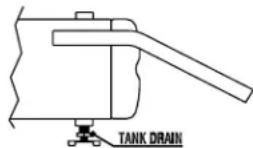
AIR TANK DRAIN VALVE: The drain valve is used to remove moisture from the air tank(s) after the air compressor is shut off. NEVER attempt to open the drain valve when more than 10 PSI of air pressure is in the air tank! To open the drain valve, turn the knob counterclockwise.
PILOT VALVE OPTION: When the adjusting knob is turned completely clockwise to the fully closed position, the air compressor operates in the Start/Stop position. When the adjusting knob is turned completely counterclockwise to the fully open position, the air compressor operates in the constant run position.
THE FOLLOWING PAGES CONTAIN OPERATING AND MAINTENANCE INSTRUCTIONS.
DO NOT ATTEMPT TO OPERATE THIS AIR COMPRESSOR UNTIL YOU HAVE READ AND UNDERSTOOD ALL SAFETY PRECAUTIONS AND INSTRUCTIONS LISTED IN THIS MANUAL.
INCORRECT OPERATION OF THIS UNIT CAN CAUSE SERIOUS INJURY!!
DO NOT ALTER OR MODIFY THIS EQUIPMENT IN ANY MANNER!
WARNING RISK OF EXPLOSION OR FIRE CAUSING SERIOUS INJURY OR DEATH!
Do not allow the motor or Motor/Pressure Switch to come in contact with flammable vapors, combustible dust, gases or other combustible materials. An electric spark may cause an explosion or fire. When using the air compressor for spray painting, place the air compressor as far away from the work area as possible, using extra air hoses instead of extension cords.

DANGER
RISK OF ELECTROCUTION!
Improper connection of the equipment-grounding conductor can result in a risk of shock or electrocution. Check with a qualified electrician or service personnel if you are in doubt as to whether the outlet is properly grounded. This product is factory equipped with a specific electric cord and plug based on the units voltage and amperage rating. This is for connection to a proper electric circuit. Only connect the product to an outlet having the same configuration as the plug. Do not use an adapter with this product. If the product must be reconnected for use on a different type of electric circuit, the reconnection shall be made by qualified service personnel. If repair or replacement of the cord or plug is necessary, do not connect the grounding wire to either flat blade terminal. The wire with insulation having an outer surface that is green with or without yellow stripes is the grounding wire.

WARNING
RISK OF ELECTRICAL SHOCK!
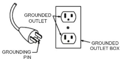
This product must be grounded. If there should be a malfunction or breakdown, grounding provides a path of least resistance for electric current to reduce the risk of electric shock. This product is equipped with a cord having an equipment-grounding conductor and a grounding type plug. The plug must be plugged into an appropriate outlet that is properly installed and grounded in accordance with all local codes and ordinances.
PREPARATION INSTRUCTIONS
INITIAL SET-UP:
- Read safety warnings before setting-up air compressor.
- Ensure the oil level in the air compressor pump is adequate. If low, add SAE-30W non-detergent oil.
LOCATION:
- In order to avoid damaging the air compressor, do not incline the air compressor transversely or longitudinally more than 10^ .
- Place air compressor at least 12 inches away from obstacles that may prevent proper ventilation. Do not place air compressor in an area: -where there is evidence of oil or gas leaks.
-where flammable gas vapors or materials may be present.
-where air temperatures fall below 32°F or exceed 104°F.
-where extremely dirty air or water could be drawn into the air compressor.
ELECTRICAL:
- USE OF AN EXTENSION CORD IS NOT RECOMMENDED because it could cause the compressor motor to overheat. It's preferable to use additional air hose instead of an extension cord.
- If use of an extension cord is unavoidable, be sure to use one heavy enough to carry the current your compressor will draw. Minimum cord sizes is as follows:
| Ampere Rating Range | Voltage | Length of cord in ft | |||||
| 120V | 25 ft | 50 ft | 100 ft | 150 ft | 200 ft | 250 ft | |
| 240V | 50 ft | 100 ft | 200 ft | 300 ft | 400 ft | 500 ft | |
| 8 - 10 | 18 | 14 | 12 | 10 | 8 | 8 | |
| 10 -12 | 16 | 14 | 10 | 8 | 8 | 6 | |
| 12 - 14 | 16 | 12 | 10 | 8 | 6 | 6 | |
| 14 - 16 | 16 | 12 | 10 | 8 | 6 | 6 | |
| 16 - 18 | 14 | 12 | 8 | 8 | 6 | 4 | |
| 18 - 20 | 14 | 12 | 8 | 6 | 6 | 4 | |
- Use only a 3-wire extension cord that has a 3-blade grounding plug and a 3-slot receptacle that will accept the plug on the compressor.
- Examine cords before using. Do not use the compressor if its cord is damaged. Do not use a damaged extension cord.
- Keep cords away from heat and sharp edges. Do not pull on a cord to disconnect a plug -- grasp the plug.
- Always shut off the compressor Pressure Switch before unplugging the compressor.

WARNING
RISK OF BODILY INJURY!
Never attempt to open the Air Tank Drain Valve when more than 10 PSI of air pressure is in the air tank!
OPERATING INSTRUCTIONS
PRE-START CHECKLIST:
- Check oil level. Add if necessary.
- Remove any moisture in the air compressor air tank. NEVER attempt to open the Air Tank Drain Valve when more than 10 PSI of air pressure is in the air tank! Remove excessive pressure with an air tool, then open the Air Tank Drain Valve in the bottom of the air tank. Close tightly when drained.
- Make sure the Motor/Pressure Switch is in the "OFF" position.
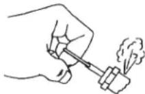
- Make sure the Safety Relief Valve is working correctly
- Make sure all guards and covers are in place and securely mounted.
START-UP:
- Read safety warnings before performing operation.
- Ensure the Motor/Pressure Switch is in the "OFF" position.
- Plug the Power Cord into a grounded outlet.
- Move the Motor/Pressure Switch to the "AUTO" position.
FOR UNITS EQUIPPED WITH DUAL CONTROL: Locate the adjustment knob at the top of the Pilot Valve.
- Turn it completely clockwise to the fully closed position. This will allow the air compressor to start building up pressure in the air tanks and shut-off when correct pressure is achieved. When pressure drops with usage, the air compressor will start automatically.
- Turn it completely counterclockwise to the fully open position. The air compressor is now set up to run continuously. When pressure reaches the preset level in the air tank, pressure will bleed through the Pilot Valve with the motor still running.
- Set pressure by adjusting the Pressure Regulator counterclockwise for less pressure and clockwise for more pressure.
- If you notice any unusual noise or vibration, stop the air compressor and refer to "Troubleshooting".
SHUTDOWN:
- To stop the air compressor, move the lever on the pressure switch box to the "OFF" position, then unplug the unit from the electric circuit. NEVER stop the air compressor by unplugging it from the power source. This could result in risk of electrocution or damage to unit.
- Drain air from the air tanks by releasing air with an attached air tool or by pulling on the Safety Relief Valve.
- Once the Air Tank Pressure Gauge registers under 10 pounds, open the Air Tank Drain Valve under each air tank to drain any moisture.
- Allow the air compressor to cool down.
- Wipe the air compressor clean and store in a safe, non-freezing area with the cord coiled up and protected from accidental damage.
EXAMPLES OF POSSIBLE CORD PLUGS AND CORRESPONDING RECEPTACLE
(A)

5-20R
Read the instruction manual before performing maintenance. The following procedures must be performed when stopping the air compressor for maintenance or service.
- Turn off air compressor.
- Disconnect Power Cord from main power supply.
- Open all drains.
- Wait for the air compressor to cool before starting service.

WARNING
RISK OF BODILY INJURY!
Never assume the air compressor is safe to work on just because it is not operating. It could restart at any time!
AC Ele. Maintenance Chart
| MAINTENANCE CHART | ||||
| PROCEDURE | DAILY | WEEKLY | MONTHLY | 200 HOURS |
| Check pump oil level X | ||||
| Oil leak inspection | X | |||
| Drain condensation in air tank (s) | X | |||
| Inspect guards/covers | X | |||
| Check for unusual noise/vibration | X | |||
| Check for air leaks | X | |||
| Clean exterior of compressor | X | |||
| Inspect air filter | X | |||
| Inspect belt | X | |||
| Check safety relief valve | X | |||
| Change pump oil * | X | |||
| Replace air filter | X | |||
*The pump oil must be changed after the first 50 hours of operation and every 200 hours or 3 months, whichever comes first.
Every two years, an Authorized Service Technician should check the check valve, intake valves and delivery valves.
TROUBLESHOOTING
| SYMPTOM | PROBABLE | CAUSE | REMEDY |
| Air compressor will not start. | Power Cord not plugged in. | Plug Power Cord into a grounded outlet. | |
| Motor/Pressure Switch turned "OFF". | Move Motor/Pressure Switch to "AUTO" position. | ||
| Motor Thermal Overload tripped on air compressor. | Turn unit off, wait 5 minutes, then press Motor Thermal Overload until click is heard. | ||
| Circuit breaker tripped or fuse blown at power source. | Reset circuit breaker or replace fuse if necessary, using only "Fusetron" type T fuses. | ||
| Check for low voltage conditions. | |||
| Disconnect any other electrical appliances from circuit or operate air compressor on its own branch circuit. | |||
| Lack of oil in the air compressor. | Add oil. (See page 9 or 11) | ||
| Extension cord is too small. | Use additional air hose instead of extension cord, or use proper wire gauge and cord length. (See page 12) | ||
| Motor voltage does not match power source. | Contact Mi-T-M® Customer Service. | ||
| Air tank pressure achieved the "Maximum setting" or "Stop pressure" of the Motor/Pressure Switch. | When Pilot Valve is set in the Start/Stop position, motor will start automatically when air tank pressure drops down to the "Cut-in" or "Start" pressure of the Motor/Pressure Switch. | ||
| Pressure release valve on Motor/Pressure Switch has not unloaded pump head pressure. | Bleed the line by moving the switch to the "Off" position. | ||
| Pilot valve's check valve stuck open. | Remove and clean or replace. | ||
| Defective motor, or Motor/Pressure Switch. | Contact Mi-T-M® Customer Service. | ||
| Air compressor will not start, but motor hums, then stops. | Extension cord too small. | Use additional air hose instead of extension cord, or use proper wire gauge and cord length. (See page 12) | |
| Loose electrical connection. | Contact qualified electrician. | ||
| Improper ventilation. | Move unit to well ventilated area. | ||
| Oil weight too heavy. | Use lighter weight oil. (See pg. 9 or 11) | ||
| Too many appliances being operated on same circuit. | Use another circuit or remove excess appliances from circuit. | ||
| Incorrect voltage, incorrect sized circuit breaker, fuse or motor. Defective motor. | Contact qualified electrician. | ||
| Defective Check Valve or Motor/Pressure Switch. | Replace. | ||
| Air compressor does not stop even though the maximum pressure allowed has been reached. | Motor/Pressure Switch not operating correctly. | Replace. |
TROUBLESHOOTING
| SYMPTOM | PROBABLE | CAUSE | REMEDY |
| Noisy operation. | Loose motor pulley or pump flywheel. | Tighten pulley and or flywheel. | |
| Lack of oil in the pump. | Add correct amount of oil. Check for bearing damage. | ||
| Carbon deposits on pistons or valves. | Remove cylinder head and inspect. Clean or replace valve plate. | ||
| Bearing, piston or connecting rod failure. | STOP THE AIR COMPRESSOR! Contact Mi-T-M® Customer Service. | ||
| Pressure drop in air tank or rapid pressure loss when air compressor is shut off. | Air leaks at connections. Allow the air compressor to build pressure to the maximum allowed. Turn off and brush a soapy water solution onto all connections. Check connections for air bubbles. Tighten the connections where leaks are present. | ||
| Defective Check Valve or Pilot Valve. | Remove, clean or replace. | ||
| Air leak in air tank. | Air tank must be replaced. Do not attempt to repair air tank! | ||
| Insufficient pressure at air tool or accessory. | Air leaks or restrictions. | Check for leaks and repair. | |
| Restricted air intake filter. | Clean or replace. | ||
| Hose or hose connections are too small or long. | Replace with larger hose or connectors. | ||
| Air compressor is not large enough for air requirement. | Use a smaller tool or larger air compressor. | ||
| Pressure Regulator not turned to high enough pressure or defective. | Adjust Pressure Regulator to proper setting or replace. | ||
| Slipping belt. | Tighten or replace. | ||
| Restricted Pilot Valve. | Clean or replace. | ||
| Air leaks from Safety Relief Valve. | Possible defective Safety Relief Valve. | Operate Safety Relief Valve manually by pulling on ring. If it still leaks, it should be replaced. | |
| Excessive air tank pressure. | Replace Motor/Pressure Switch. Clean, reset or replace Pilot Valve. | ||
| Air leaks at pump. | Defective gaskets. | Torque head bolts: Single Stage= 17 ft./lbs. Two Stage= 33 ft./lbs. | |
| Air continues to leak at Motor/Pressure Switch while motor is running. | Defective Motor/Pressure Switch. | Replace. | |
| Air blowing from Air Intake Filter. | Damaged inlet (reed) valve. | Replace. |
TROUBLESHOOTING
| SYMPTOM | PROBABLE | CAUSE | REMEDY |
| When in the Start/Stop Option, motor runs continuously. | Motor/Pressure Switch does not shut off motor when air compressor reaches "cut-out" pressure and safety relief valve activates. | Move the Motor/Pressure Switch to the "OFF" position. If the motor does not shut off, unplug the air compressor. If the electrical contacts are welded together, replace the pressure switch. | |
| Air compressor is incorrectly sized. | Limit the air pressure to the capacity of the air compressor. Either use a smaller tool or a larger air compressor. | ||
| Moisture in discharge air. Condensation in air tank caused by high level of atmospheric humidity. | Run air compressor a minimum of one hour to prevent condensation buildup. Drain air tank after every use. Drain air tank more often in humid weather and use an air line filter. | ||
| Excessive oil consumption or oil in hose. | Restricted air intake filter. | Clean or replace. | |
| Air compressor on unlevel surface. | Do not incline the air compressor more than 10^ in any direction while running. | ||
| Crankcase overfilled with oil. | Drain oil. Refill to proper level with SAE-30W non-detergent oil. | ||
| Wrong viscosity. | Drain oil. Refill to proper level with SAE-30W non-detergent oil. | ||
| Plugged oil dipstick vent. | Clean. | ||
| Oil leaks. | Tighten pump bolts to torque stated in Parts List, or replace gaskets. | ||
| Worn piston rings or scored cylinder. | Contact Mi-T-M®Customer Service. | ||
| Oil has milky appearance. Water in oil due to condensation. Change oil and move air compressor to a less humid environment. | |||
Unit runs backward. Reversed wiring. Contact qualified electrician.
Mi-T-M PORTABLE ELECTRIC AIR COMPRESSOR STATEMENT OF WARRANTY
Mi-T-M ^® warrants all parts, (except those referred to below), of your new air compressor to be free from defects in materials and workmanship during the following periods:
For Two (2) Years from the date of original purchase:
Compressor Pump Plumbing
Tank Assembly
For Six (6) months from date of original purchase;
Pressure Switch Regulator
Check Valve Pilot Valve
Copper/stainless steel line
For Ninety (90) days from the date of original purchase:
Pressure Gauges Safety Relief Valves
Drain Valves
Defective parts not subject to normal wear and tear will be repaired or replaced at our option during the warranty period. In any event, reimbursement is limited to the purchase price paid.
EXCLUSIONS
- Motor is covered under separate warranty by its respective manufacturer and is subject to the terms set forth therein.
- Normal wear parts:
Isolators
Air Filter - This warranty does not cover parts damaged due to normal wear, abnormal conditions, misapplication, misuse, accidents, operation at other than recommended voltage, pressures or temperature, improper storage or freight damage. Parts damaged or worn by operation in dusty environments are not warranted. Failure to follow recommended operating and maintenance procedures also voids warranty.
- Labor charges, loss or damage resulting from improper operation, maintenance (other than routine air tank draining and oil changes, if applicable) or repairs made by persons other than a Mi-T-M® Authorized Service Center.
- The use of other than Genuine Repair Parts will void warranty. Parts returned, prepaid to our factory or to an Authorized Service Center will be inspected and replaced free of charge if found to be defective and subject to warranty. Under no circumstances shall the manufacturer bear any responsibility for loss of use of the unit, loss of time or rental, inconvenience, commercial loss or consequential damages. There are no warranties which extend beyond the description of the face hereof.
For Service or Warranty Consideration, contact
Mi-T-M® Corporation, 50 MI-T-M Drive, Peosta, IA 52068
563-556-7484 / 800-553-9053 / Fax 563-556-1235
Monday - Friday 8:00 a.m. - 5:00 p.m. CST
TABLE DES MATIERES
INTRODUCTION 23
IMPORTANT 23
INSPECTION 23
IMPORTANTES CONSIGNES DE SECURITE 24-27
AC Ele. Maintenance Chart French
AC Ele. Maintenance Chart Spanish

ADVERTENCIA
Lunes - Viernes 8:00 a.m. - 5:00 p.m. CST
- PORTABLE ELECTRIC AIR COMPRESSOR
- OPERATOR'S MANUAL
- TABLE OF CONTENTS
- IMPORTANT SAFETY INSTRUCTIONS....4-7
- ▲ WARNING
- INTRODUCTION
- IMPORTANT!
- SERIAL NUMBER
- ! SAVE THESE INSTRUCTIONS !
- EXPLODED VIEW & EXPLANATION OF AIR COMPRESSOR FEATURES
- WARNING RISK OF EXPLOSION OR FIRE CAUSING SERIOUS INJURY OR DEATH!
- DANGER
- RISK OF ELECTROCUTION!
- WARNING
- RISK OF ELECTRICAL SHOCK!
- PREPARATION INSTRUCTIONS
- INITIAL SET-UP:
- LOCATION:
- ELECTRICAL:
- RISK OF BODILY INJURY!
- OPERATING INSTRUCTIONS
- PRE-START CHECKLIST:
- START-UP:
- SHUTDOWN:
- EXAMPLES OF POSSIBLE CORD PLUGS AND CORRESPONDING RECEPTACLE
- Mi-T-M PORTABLE ELECTRIC AIR COMPRESSOR STATEMENT OF WARRANTY
- EXCLUSIONS
- TABLE DES MATIERES
- ADVERTENCIA
Brand : Mi-T-M
Model : AM1-PE15-20M
Category : Compressor