
Geneva T0729 - Lighting Vaxcel - Free user manual and instructions
Find the device manual for free Geneva T0729 Vaxcel in PDF.

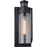
| Product Type | Outdoor light fixture with motion detector |
| Brand | Vaxcel |
| Model | Geneva T0729 |
| Power Supply | 120 V AC, 60 Hz |
| Maximum Bulb Wattage | 60 W (compatible with dimmable LED bulbs) |
| Detector Type | Passive infrared (PIR) |
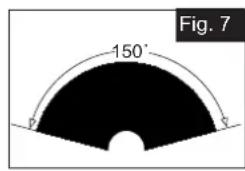
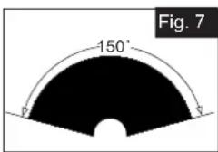
| Detection Angle | 150 degrees |
| Detection Range | Up to 9.14 m (30 ft), adjustable |
| Time Delay | Adjustable from 5 seconds to 3 minutes |
| Operating Modes | Test, Off, Auto, PC (dusk-to-dawn), Manual override |
| Operating Temperature | -30 °C to 45 °C |
| Material | Metal and glass |
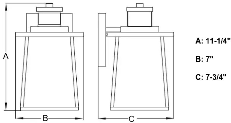
| Dimensions (approx.) | 28.6 x 18 x 19.7 cm |
| Estimated Weight | 2.5 kg |
| Warranty | 5-year limited (motion detector and LED modules), 1-year finish |
| Installation | Wall mount, requires power cut and grounding |
| Maintenance | Clean the detector lens with a soft cloth every 1-2 months |
| Safety | Cut off power before installation and bulb replacement |
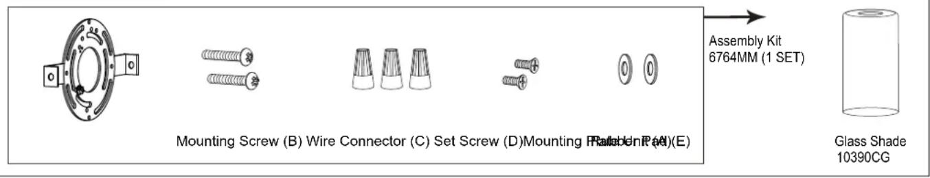
| Replacement Parts Available | Mounting plate, screws, rubber pads, glass shade |
Frequently Asked Questions - Geneva T0729 Vaxcel
User questions about Geneva T0729 Vaxcel
0 question about this device. Answer the ones you know or ask your own.
Ask a new question about this device
Download the instructions for your Lighting in PDF format for free! Find your manual Geneva T0729 - Vaxcel and take your electronic device back in hand. On this page are published all the documents necessary for the use of your device. Geneva T0729 by Vaxcel.
USER MANUAL Geneva T0729 Vaxcel
ASSEMBLY AND INSTALLATION INSTRUCTIONS
T0729
WARNING: Turn off the main power at circuit breaker before installing fixture.
NOTE: 1. Before installing, consult local electrical codes for wiring and grounding requirements. 2. Read and save these instructions.
Important to Know
- Read all instructions carefully before installation and operation.
- If you are not familiar with state and local electrical codes, it is recommended that you consult with a qualified electrician.
- Before installation, shut off power at the main fuse or circuit breaker box. Be aware that simply turning off the wall switch is not sufficient to prevent an electrical shock.
- This fixture requires a 120V AC, 60 Hz power source.
- Do not attempt to take the lantern apart; there are no serviceable parts inside.
- To avoid sensor damage by lightning or electrical surge, make sure the ground wire is securely connected.
- For general safety and to avoid any possible damage to the sensor, be sure the power is switched "off" before replacing the bulb.
- Compatible with most LED dimmable bulbs.
Maximum Wattage: 60W Bulb
Working Temperature: -22°F\~113°F
Features
- Energy saving fixture.
- When in manual override mode, use wall switch to keep the light ON till dawn.
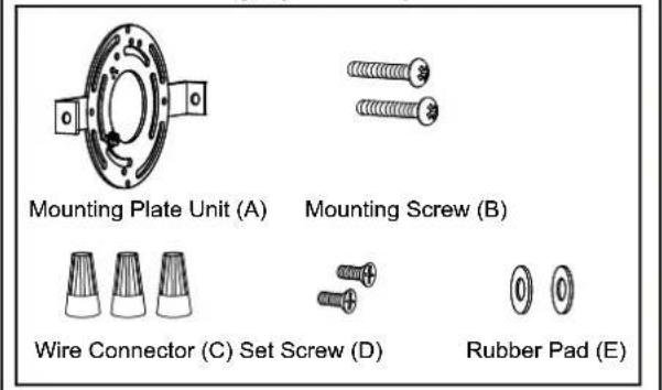
Hardware Package (included):
Installation Steps
Turn off the power at fuse or circuit box
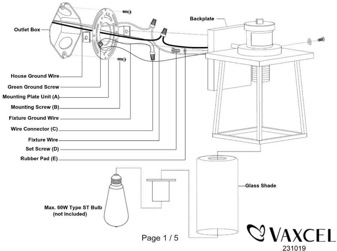
- Unscrew the two set screws (D), remove the two rubber pads (E) and the mounting plate unit (A) from the backplate.
- Attach the mounting plate unit (A) to the outlet box by using two mounting screws (B).
-
Pull out the source wires from the outlet box. Make wire connections using wire connectors (C) as follows:
-
Connect the hot wire (black insulation) from the fixture to the black wire from the power source.
- Connect the neutral wire (white insulation) from the fixture to the white wire from the power source.
- Attach the fixture ground wire (bare wire) to the mounting plate unit (A) with the green ground screw, then depending on local code, connect it to the house ground wire with the wire connector (C).
Carefully put all of the wires back into the outlet box.
- Attach the backplate of the fixture to the mounting plate unit (A) by aligning holes, then secure it with two rubber pads (E) and two set screws (D).
Note: With silicone caulk compound, caulk completely around where the backplate meets with the wall surface to prevent water from seeping into the outlet box. - Attach the glass shade to the socket and secure it with socket ring.
- Install the bulb (not included). Check relamping label at socket area or packaging for maximum wattage allowed.
Turn on the power at fuse or circuit box.
The Position of Control Panel
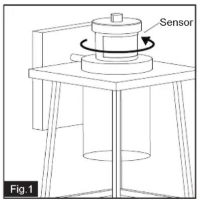

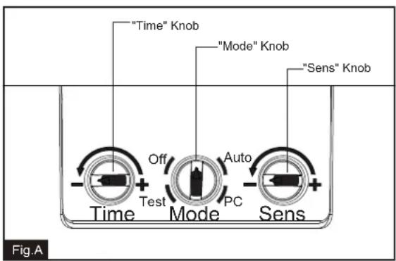
Step 1: Rotate the sensor clockwise or counter-clockwise at maximum 90 degree to access the adjustable knobs. (See Fig.1)
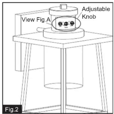
Step 2: Adjust time and sensitivity, choose the mode you want by turning the knob. (See Fig.2 and Fig.A).
Step 3: Restore the sensor to original position by rotating to the opposite direction. (See Fig.3)
Function and Operation
MODES OF OPERATION
Choose a mode by turning the rotary knob. The light will turn on immediately when power is applied. Wait for 30 seconds to allow the sensor to warm up.
1. Test MODE (daytime and nighttime operation)
- The light will turn on when motion is detected, and stay on as long as the motion continues. The light will turn to low-level brightness (30%) after 5 seconds when motion is no longer detected.
2. Off MODE (nighttime operation only)
- At dusk, the light stays off and will turn to high-level brightness (full brightness) when motion is detected, and stay on as long as the motion continues. When the motion stops, the light will stay on for the predetermined time set (5\~180 seconds), then the light will turn off.
3. Auto MODE (nighttime operation only)
- At dusk, the light will turn on when motion is detected, and stay on as long as the motion continues. When the motion stops, the light will remain on for the predetermined time set (5\~180 seconds) and then turn to low-level brightness (30%).
- The light will turn off automatically at dawn.
4. PC MODE (nighttime operation only)
- The light will turn on automatically at dusk and turn off at dawn.
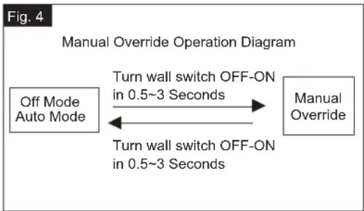
5. Manual Override MODE (nighttime operation only)
- To shift to the manual override mode, set the switch to "Auto" or "Off" mode. Turn the wall switch "OFF" and "ON" within 3 seconds. The light will remain on until dawn. To restore to the "Auto" or "Off" mode, turn the wall switch "OFF" and "ON" within 3 seconds. (See Fig.4)
- The light will last for one night only and turn off automatically at dawn.
Note: 1. Always keep the wall switch in the "ON" position (including daytime).
- Please notice the warm up time is 30 seconds, any operations are invalid during this time.
Customization Options Shut-off Delay
- The Shut-off delay is the length of time that the light will stay on after motion stops.
- The Shut-off delay can be adjusted by using the "Time" knob when the knob is set in "Off" or "Auto" mode. (See Fig.5)
- The range of shut-off delay is 5 seconds to 3 minutes.
- Rotate the knob clockwise for increasing the shut-off delay.
- Rotate the knob counterclockwise for decreasing the shut-off delay.
flowchart
graph LR
    A["Off Mode Auto Mode"] -->|Turn wall switch OFF-ON in 0.5~3 Seconds| B["Manual Override"]
    B -->|Turn wall switch OFF-ON in 0.5~3 Seconds| A
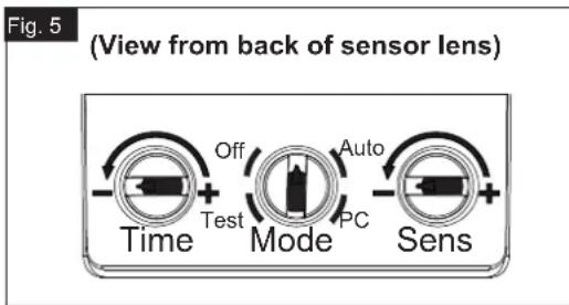
Sensitivity of Motion Sensor
- The sensitivity can be adjusted from 5 to 30 feet by using the "Sens" knob. (See Fig.5).
- Turn the knob clockwise for increased sensitivity.
- Turn the knob counterclockwise for decreased sensitivity.
NOTE:
- The sensitivity of the motion sensor will increase as the environmental temperature gets colder. For best performance, gently clean the lens with a soft cloth every 1 or 2 months to ensure maximum sensitivity.
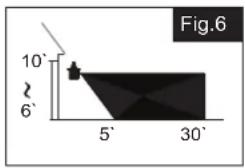
- When installed at a height of 6.5 feet, at 77 degrees Fahrenheit, the light will provide a maximum detection distance of 30 feet and detection range of 150 degrees. (See Fig.6, Fig.7)
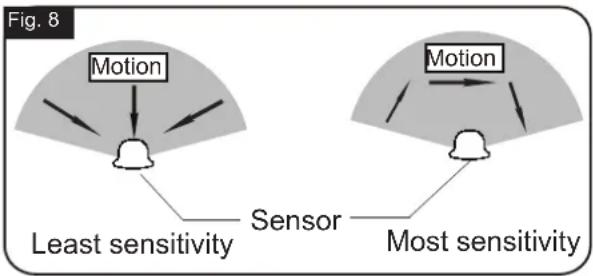
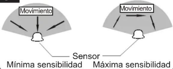
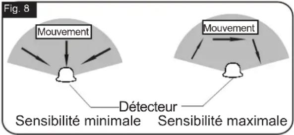
- The sensor will be more sensitive to motion across its detection path than motion directly towards it. (See Fig.8)
- To reduce possible nuisances, do not mount the fixture near a heat source like an air conditioner, vent or furnace exhaust, or in a direction facing any reflecting object or other light source.
Where you install your light is important: Be sure the light is mounted straight on the wall; otherwise, the detection distance may be limited.
flowchart
graph TD
    A["Least sensitivity"] --> B["Motion"]
    C["Most sensitivity"] --> D["Motion"]
    B --> E["Sensor"]
    D --> E
    style A fill:#f9f,stroke:#333
    style C fill:#f9f,stroke:#333
TROUBLESHOOTING
Refer to following information to solve your problems.
| SYMPTOM | DAY/NIGHT | POSSIBLE CAUSE | SOLUTION |
| If the light isn't on | Day | Rotary knob is not set in the test mode. | Set the rotary knob in the test mode for testing. |
| Night | Wall switch or circuit breaker is off. | Turn on wall switch or circuit breaker. | |
| Light bulb may be burned out. | Test the light bulb on normal working light fixture. | ||
| Light bulb is loose. | Tighten the light bulb. | ||
| Incorrect or loose wire connections. | Check wire connections. | ||
| Too much sunlight is shining onto sensor in the early evening. | Relocate fixture away from western facing wall. | ||
| Too much light is shining onto sensor due to another light source, such as a street lamp or other light fixture. | Eliminate or turn off other light source, block other light source from shining onto sensor, or relocate fixture. | ||
| If the light stays on | Day | The fixture may be installed in shaded area. | Only need to relocate fixture. |
| On cloudy or overcast days, the light may stay on longer than anticipated. | No corrective action needed. | ||
| Night | Still on the manual override mode. | Turn off the light, then turn it on after 5 seconds. | |
| False triggering caused by a heat source, such as a heater, dryer vent, or heated swimming pool. | Eliminate heat source or relocate fixture. | ||
| The knob is not set in any mode. | Rotate it again to the mode you want. |
TROUBLESHOOTING (continued)
| SYMPTOM | DAY/NIGHT | POSSIBLE CAUSE | SOLUTION |
| If the light is blinking | Night | Passing cars and reflective objects interfere with the sensor. | Relocate fixture. |
| The light comes on for no apparent reason | Night | Street or sidewalk traffic is triggering motion sensor. | Adjust the "Sens" knob to reduce the sensitivity. |
| False triggering caused by a heat source, such as a heater, dryer vent, or heated swimming pool. | Eliminate heat source or relocate fixture. |
The following parts are available for reorder if damaged or missing.
Spare Parts List:
5 Year Limited Warranty
Vaxcel warrants all of our products against defects in workmanship and finishes for one year following the date of shipment.
In addition:
- Any product with an integrated motion sensor or dusk-to-dawn photocell is supported by a 5-year warranty for the functionality of the product.
- Any product with integrated LED modules is covered by a 5-year warranty on the LED functionality.
Exclusions: This warranty does not include the failure of products from extreme acts of nature; environmental conditions not suited for the products intended use; operation in temperatures outside of the range specified in the instruction manual; usage with improper power supply, power surges or dips. For coastal locations, some corrosion is considered normal for the environment.
Vaxcel reserves the right to repair, replace or issue a credit for any properly installed product, provided it is returned per RMA instruction. This warranty is limited to the cost of the product only and does not extend to transportation, installation or replacement costs.
How can warranty service be obtained?
info@vaxcel.com
1-800-482-9235
INSTRUCCIONES DE ENSAMBLAJE
E INSTALACIÓN
T0729
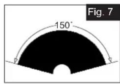
Fig. 8
flowchart
graph TD
    A["Movimiento"] --> B["Sensor"]
    C["Mínima sensibilidad"] --> B
    D["Máxima sensibilidad"] --> B
    E["Movimiento"] --> F["Sensor"]
    G["Máxima sensibilidad"] --> F
    style A fill:#f9f,stroke:#333
    style C fill:#f9f,stroke:#333
    style D fill:#f9f,stroke:#333
    style E fill:#f9f,stroke:#333
    style F fill:#f9f,stroke:#333
RÉSOLUTION DES PROBLÈMES (suite)
- ASSEMBLY AND INSTALLATION INSTRUCTIONS
- WARNING: Turn off the main power at circuit breaker before installing fixture.
- Important to Know
- Features
- Installation Steps
- Turn off the power at fuse or circuit box
- The Position of Control Panel
- Function and Operation
- MODES OF OPERATION
- Test MODE (daytime and nighttime operation)
- Off MODE (nighttime operation only)
- Auto MODE (nighttime operation only)
- PC MODE (nighttime operation only)
- Manual Override MODE (nighttime operation only)
- Customization Options Shut-off Delay
- Sensitivity of Motion Sensor
- NOTE:
- TROUBLESHOOTING
- TROUBLESHOOTING (continued)
- In addition:
- INSTRUCCIONES DE ENSAMBLAJE
- E INSTALACIÓN
- RÉSOLUTION DES PROBLÈMES (suite)
Brand : Vaxcel
Model : Geneva T0729
Category : Lighting