
809 - Industrial fan Canarm - Free user manual and instructions
Find the device manual for free 809 Canarm in PDF.


| Product Type | Industrial fan |
| Brand | Canarm |
| Model | 809 |
| Series | 800 |
| Usage | Ventilation and air circulation in industrial premises |
| Power supply | Mains connection according to motor specifications (voltage and phase indicated on the nameplate) |
| Grounding | Mandatory: motor housing and frame must be connected to a suitable ground |
| Protection of rotating parts | Required if not protected by ducts, cabinets or covers |
| Drive type | By V-belts and pulleys |
| Bearings | Ball bearings, permanently lubricated (fan); pillow block bearings requiring lubrication every 6 to 12 months |
| Belt maintenance | Check tension and alignment; replace with a complete set if worn |
| Cleaning | Clean the wheel periodically to prevent imbalance |
| Warranty | 1 year from purchase date (parts and labor) |
| Customer service | Canada: 1-800-265-1833, USA: 1-800-267-4427, French: 1-800-567-2513 (Mon-Fri 8am-5pm EST) |
| Spare parts available | Bearings, belts, pulleys, wheel, motor support |
| Repairability | Bearings replaceable; belts and pulleys adjustable; exploded view provided |
| Safety instructions | Disconnect power before maintenance; do not open doors during operation |
Frequently Asked Questions - 809 Canarm
User questions about 809 Canarm
0 question about this device. Answer the ones you know or ask your own.
Ask a new question about this device
Download the instructions for your Industrial fan in PDF format for free! Find your manual 809 - Canarm and take your electronic device back in hand. On this page are published all the documents necessary for the use of your device. 809 by Canarm.
USER MANUAL 809 Canarm
400/800/900 SERIES UTILITY BLOWERS

CANARM®
HVAC
OPERATION INSTRUCTIONS AND PARTS MANUAL
READ AND SAVE THESE INSTRUCTIONS
Models: 407 through 425, 809 through 818, 809-2 through 818-2, 907, 909-7, 909, 910-8, 910, 912-9, 912, 915-10, 915, 918-13, 918, 920, 922, 925, 927, 930, 933, 936
WARRANTY
CANARM Ltd. warrants every new product to be free of defects in material and workmanship, to the extent that, within a period of one year from the date of purchase CANARM Ltd. shall either repair or replace at CANARM's option, any unit or part thereof, returned freight prepaid, and found to be defective.
This warranty does not include any labour or transportation costs incidental to the removal and reinstallation of the unit at the user's premises. Components repaired or replaced are warranted through the remainder of the original warranty period only.
This warranty applies to the original purchaser-user only; it is null and void in case of alteration, accident, abuse, neglect, and operation not in accordance with instructions.
NOTICE: No warranty claims will be honored by CANARM Ltd. unless prior authorization is obtained.
GENERAL SAFETY
Rotating parts, (pulleys, shafts and belts) on fans should not be exposed. Where these components are not protected by ductwork, cabinets or covers, appropriate guards should be employed to restrict exposure to rotating parts. Access doors should not be opened with the fan operating to avoid foreign objects being drawn into the system. On initial start-up, a careful inspection should be carried out to ensure no foreign material is present which could become airborne in the system.
Read installation and operation instructions carefully before attempting to install, operate or service Canarm/Delhi 400/800/900 Series. Failure to comply with instructions could result in personal injury and/or property damage. Retain instructions for future reference.
Installation or Product problems? Do not return to store of purchase.
Contact Canarm Service at 1-800-265-1833 (CANADA) 1-800-267-4427 (U.S.A.)
1-800-567-2513 (EN FRANCAIS) Monday to Friday 8:00 - 5:00pm e.s.t.
Canarm Ltd. - Corporate Head Office 2157 Parkedale Avenue, PO Box 367 Brockville, Ontario Canada K6V 5V6
Tel: (613) 342-5424; Fax: (613) 342-8437
www.canarm.com
hvacsales@canarm.ca
400_800_900 SERIES_04_08_2022 Page 1 of 4
BEFORE YOU BEGIN
Inspect unit for damage, report any shipping damage to carrier. Check all fasteners, re-tighten as required. Rotate the blower wheel by hand to ensure free rotation. If rubbing occurs, loosen the set screw(s), re-position the wheel to the shaft center, re-tighten set screws.
INSTALLATION
-
Prior to installing the motor, ensure the wheel rotates freely by turning by hand. If rubbing occurs, loosen the wheel set screws and re-position the wheel to the centre of the shaft. Retighten all set screws.
-
Establish the preferred discharge direction and re-tighten by fastening through the frame holes located at the bottom of the blower.
DESCRIPTION
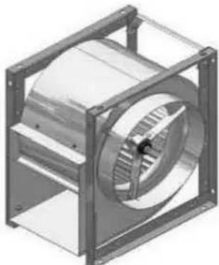
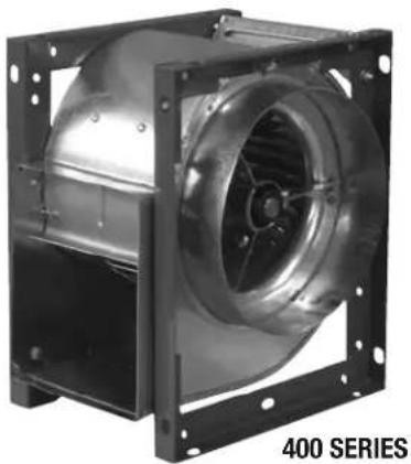
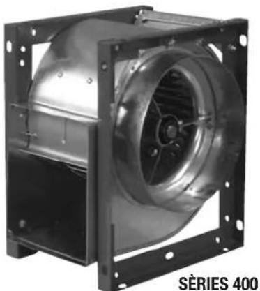
FIGURE 1: 400 SERIES
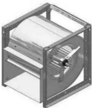
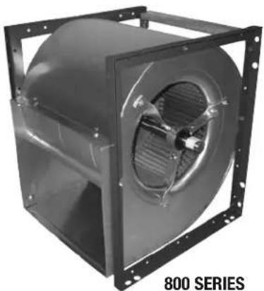
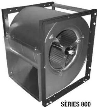
FIGURE 2: 800 SERIES
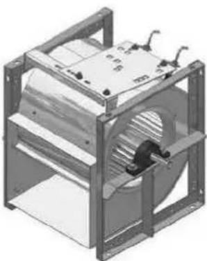
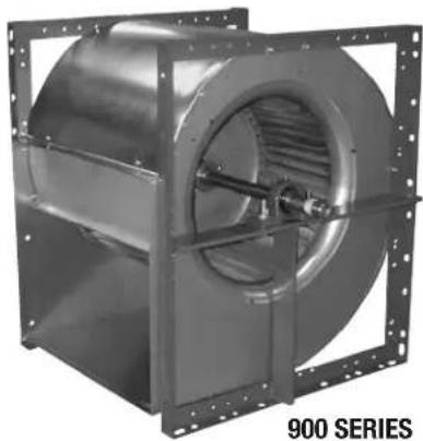
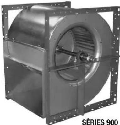
FIGURE 3: 900 SERIES
MOTOR, PULLEYS & BELTS
- Mount the blower pulley on the blower shaft and tighten the set screw securely on the key of the shaft.
- Mount the motor pulley on the motor shaft. Leave some clearance between the pulley and the motor end bell.
- Position the square head bolts in the groove of the motor mounting bracket and install the motor loosely on the bracket using the hardware provided. Bolt the motor adjusting leg to shaft side of the motor base.
NOTE: This may not be applicable if an optional motor plate was purchased (see Figure 5). - With the adjusting bolt in the minimum positon, install the V belt(s) within the sheave grooves. Position the motor on the motor bracket to ensure proper pulley alignment (see Figure 6) and tighten the motor mounting hardware to secure the motor position. (A straight edge across the face of the driven pulley should be parallel to the belt once proper alignment has been achieved).
NOTE: Adjustments in the variable speed pulley require pulley realignment. - Tighten the adjusting bolt to tension the V-belt and lock in place using the keps nut (see Figure 4).
NOTE: Ideal belt tension is the lowest tension at which the belt will not slip during start up.
| MODELMAX. HPSHAFT DIA.WEIGHT (Ibs) | |||
| 40713/4"16 | |||
| 40923/4"23 | |||
| 41023/4"26 | |||
| 41223/4"30 | |||
| 41531"56 | |||
| 41851"57 | |||
| 4207 - 1/2 2 - 3/16"189 | |||
| 4227 - 1/2 3 - 3/16"214 | |||
| 425 | 10 | 1 - 3/16"252 | |
| MODELMAX. HPSHAFT DIA.WEIGHT (Ibs) | |||
| 80933/4"28 | |||
| 81033/4"32 | |||
| 81231"43 | |||
| 81531"57 | |||
| 81851" | 125 | ||
| 809-2 | 33/4"95 | ||
| 810-2 | 33/4" | 112 | |
| 812-2 | 31" | 130 | |
| 815-2 | 51" | 195 | |
| 818-2 | 51" | 302 | |
| MODELMAX. HPSHAFT DIA.WEIGHT (Ibs) | |||
| 90733/4"28 | |||
| 909-7 | 33/4"34 | ||
| 90933/4"40 | |||
| 910-8 | 33/4"43 | ||
| 91051"52 | |||
| 812-9 | 51"56 | ||
| 91251"69 | |||
| 915-10 | 51"72 | ||
| 91551"87 | |||
| 918-13 | 5 | 1 - 3/16" | 96 |
| 918 | 10 | 1 - 3/16"120 | |
| 920-18 | 15 | 1 -7/16" | 212 |
| 920 | 15 | 1 -7/16" | 220 |
| 922 | 15 | 1 -7/16" | 245 |
| 925 | 15 | 2 - 3/16"297 | |
| 927 | 50 | 2 - 7/16"385 | |
| 930 | 100 | 2 - 11/16" | 470 |
| 933 | 100 | 2 - 11/16" | 590 |
| 936 | 100 | 2 - 11/16" | 640 |
FIGURE 4: MOTOR MOUNTING
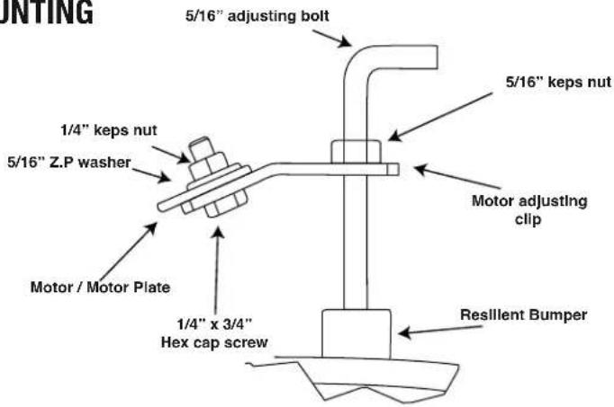
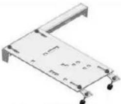
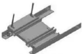
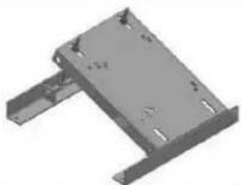
FIGURE 5: OPTIONAL MOTOR MOUNTING
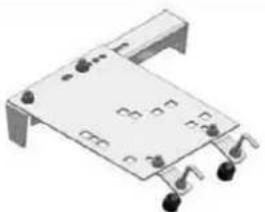
3HP MOTOR PLATE
5HP MOTOR PLATE
1-15 HP MOTOR PLATE
20-50 HP MOTOR PLATE

WARNING
EXCESSIVE BELT TENSION IS THE MOST FREQUENT CAUSE OF BEARING WEAR AND RESULTING NOISE. PROPER BELT TENSION IS CRITICAL FOR QUIET EFFICIENT OPERATION.
Ideal belt tension is the lowest value under which belt slip will not occur at peak load conditions.
FIGURE 6
PULLEY ALIGNMENT
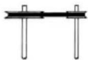
CORRECT
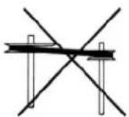
WRONG
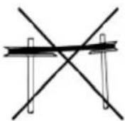
WRONG
FIGURE 7
BEARING REPLACEMENT
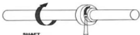
(1) 2017年1月1日
ELECTRICAL

WARNING
ENSURE POWER SUPPLY IS DISCONNECTED & LOCKED OUT PRIOR TO MAKING ELECTRICAL CONNECTIONS.
Before connecting the motor to the electrical supply, check the electrical characteristics and wiring instructions as indicated on the motor nameplate or inside the conduit box cover to ensure proper voltage and phase. Complete electrical connections as indicated.

WARNING
A GROUND WIRE MUST BE CONNECTED FROM THE MOTOR HOUSING TO A SUITABLE ELECTRICAL GROUND.

WARNING
A GROUND WIRE MUST BE CONNECTED FROM THE UNIT CHASSIS TO A SUITABLE ELECTRICAL GROUND.
OPERATION
- Complete the electrical connections, energize the unit momentarily and ensure proper wheel rotation.
- Apply full power.
- With all ducts attached, the access doors in place and the air system in full operation, measure the motor current and ensure that it is less than the rated full load motor amperage as indicated on the motor nameplate.
MAINTENANCE

WARNING
ENSURE POWER SUPPLY IS DISCONNECTED & LOCKED OUT PRIOR TO MAKING ELECTRICAL CONNECTIONS.
- Inspect and tighten all bearing collar and wheel set screws after the first 50 to 100 hours of operation and periodically thereafter.
- Follow motor manufacturer's instructions for motor lubrication. Remove any excess lubrication.
- Check the drives.
a. Tighten set screws on pulleys, wheel and bearing locking collars.
b. Check belt tension and alignment.
c. Replace cracked or worn belts.
- Blower bearings are permanently lubricated and require no further lubrication.
- Inspect V-belts for wear and proper tension. If it is necessary to replace one belt on a multiple belt drive, replace all the belts with a matched set. Do not use belt dressing.
- Clean the blower wheel periodically. Material build up on the blades can cause wheel imbalance which may result in wheel or bearing failure.
- To reinstall replacement ball bearings on spider bearing bracket assemblies, press the locking collar against the inner ring of the bearing and turn in the direction of the shaft rotation until engaged. Insert a drift pin into the pin hole and tap lightly to set. Tighten set screw on locking collar firmly. (see Figure 7). If replacing the pillow block bearings, simply loosen the set screws and remove the mounting hardware. When re-installing, bolt the pillow block to the T-bar support, then position the set screw to be parallel and on top of the key stock of the shaft. Torque set screw to specified values.
- Spider bracket bearings come pre-lubricated from the manufacturer, and require no re-lubrication. Pillow block bearings are pre-lubricated by the manufacturer. Generally, these bearings should be lubricated at six to twelve month intervals. The recommended lubricant is Shell Alvania #2 or S3. A small amount of grease should be added slowly when the shaft is rotating. Note: Over greasing may cause damage to the bearing. Avoid rupturing the bearing seal.
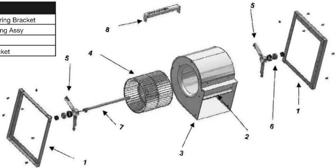
- Should further service to the blower be necessary, refer to the exploded view illustration (see Figure 8).
FIGURE 8: EXPLODED VIEW (800 SERIES)
Refer to Figure 3 (900 Series) for an illustration on T-Bar's and Pillow block bearings.
PARTS LIST
| 1. Framework 5. Bearing Bracket |
| 2. Baffle 6. Ball Bearing Assy |
| 3. Housing 7. Shaft |
| 4. Wheel 8. Motor Bracket |
SÉRIES 400/800/900 VENTILATEUR UTILITAIRE

CANARM®
HVAC
MODE D'OPÉRATION ET LISTE DES PIÈCES
LIRE ET GARDER CES INSTRUCTIONS
Modéls: 407 à travers 425, 809 à travers 818, 809-2 à travers 818-2, 907, 909-7, 909, 910-8, 910, 912-9, 912, 915-10, 915, 918-13, 918, 920, 922, 925, 927, 930, 933, 936
GARANTIE
2157 Parkedale Avenue, PO Box 367
Brockville, Ontario
Canada
K6V 5V6
Tel: (613) 342-5424; Fax: (613) 342-8437
www.canarm.com/fr/
hvacsales@canarm.ca
400_800_900 SÉRIES_FR_04_08_2022 Page 1 de 4
AVANT DE DÉBUTER
FIGURE 1: SÉRIES 400
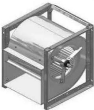
FIGURE 2: SÉRIES 800
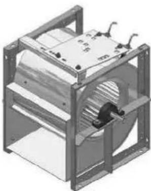
FIGURE 3: SÉRIES 900
| MODÈLE | PUSSANCE MAX | DIAMÈTRE DE L'ARBRE | POIDS |
| 40713/4"16 | |||
| 40923/4"23 | |||
| 41023/4"26 | |||
| 41223/4"30 | |||
| 41531"56 | |||
| 41851"57 | |||
| 4207 - 1/2 2 - 3/16"189 | |||
| 4227 - 1/2 3 - 3/16"214 | |||
| 42510 | 1 - 3/16"252 | ||
| MODÈLE | PUSSANCE MAX | DIAMÈTRE DE L'ARBRE | POIDS |
| 80933/4"28 | |||
| 81033/4"32 | |||
| 81231"43 | |||
| 81531"67 | |||
| 81851" | 125 | ||
| 809-2 | 33/4"95 | ||
| 810-2 | 33/4" | 112 | |
| 812-2 | 31" | 130 | |
| 815-2 | 51" | 195 | |
| 818-2 | 51" | 302 | |
| MODÈLE | PUSSANCE MAX | DIAMÈTRE DE L'ARBRE | POIDS |
| 90733/4"28 | |||
| 909-7 | 33/4"34 | ||
| 90933/4"40 | |||
| 910-8 | 33/4"43 | ||
| 91051"52 | |||
| 812-9 | 51"56 | ||
| 91251"69 | |||
| 915-10 | 51"72 | ||
| 91551"87 | |||
| 918-13 | 5 | 1 - 3/16" | 96 |
| 91810 | 1 - 3/16"120 | ||
| 920-18 | 15 | 1 -7/16" | 212 |
| 92015 | 1 -7/16" | 220 | |
| 92215 | 1 -7/16" | 245 | |
| 92515 | 2 - 3/16"297 | ||
| 92750 | 2 - 7/16"385 | ||
| 930 | 100 | 2 - 11/16"470 | |
| 933 | 100 | 2 - 11/16"590 | |
| 936 | 100 | 2 - 11/16"640 | |
MOTEUR, POULIES & COURROIES
3 HP PLAQUE DE MOTEUR 20-50 HP PLAQUE DE MOTEUR1-15 HP PLAQUE DE MOTEUR5 HP PLAQUE DE MOTEUR

MISE EN GARDE
UNE TENSION EXCESSIVE DE LA COURROIE EST LA CAUSE LA PLUS FRÉQUENTE D'USURE DES ROULEMENTS ET DES BRUITS. UNE TENSION ADÉQUATE EST CRITIQUE POUR UN FONCTIONNEMENT EFFICACE ET SILENCIEUX.
- 400/800/900 SERIES UTILITY BLOWERS
- CANARM®
- HVAC
- WARRANTY
- GENERAL SAFETY
- BEFORE YOU BEGIN
- INSTALLATION
- MOTOR, PULLEYS & BELTS
- WARNING
- ELECTRICAL
- OPERATION
- MAINTENANCE
- FIGURE 8: EXPLODED VIEW (800 SERIES)
- SÉRIES 400/800/900 VENTILATEUR UTILITAIRE
- GARANTIE
- AVANT DE DÉBUTER
- MOTEUR, POULIES & COURROIES
- MISE EN GARDE
Brand : Canarm
Model : 809
Category : Industrial fan