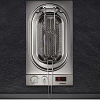
VF230614 - Deep fryer GAGGENAU - Free user manual and instructions
Find the device manual for free VF230614 GAGGENAU in PDF.


| Product type | Built-in electric deep fryer |
| Brand | Gaggenau |
| Model | VF230614 |
| Category | Deep fryer |
| Power supply | 240 V, 60 Hz, 16 A (max) |
| Maximum power | Approx. 2500 W (estimated) |
| Installation type | Built-in into worktop |
| Tank material | Stainless steel |
| Main functions | Frying, temperature adjustment (not specified) |
| Safety | Mandatory grounding, automatic shut-off (not specified) |
| Maintenance and cleaning | Clean with hob cleaning cream |
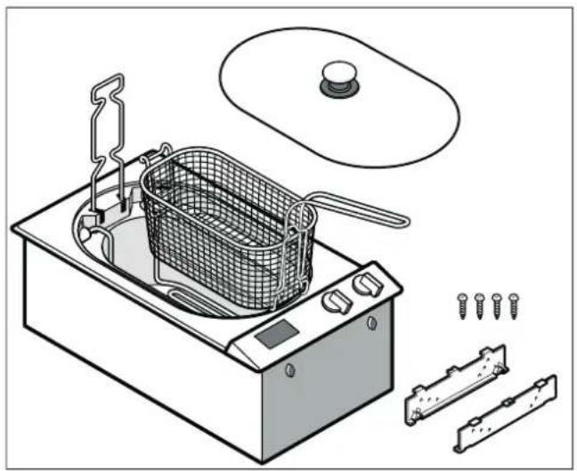
| Included accessories | Fixing rails, optionally cover VD 201 (optional) |
| After-sales service | CA 800 828 9165 (Canada) |
| Dimensions (W x D x H) | Approx. 300 x 500 x 200 mm (estimated) |
| Net weight | Approx. 10 kg (estimated) |
Frequently Asked Questions - VF230614 GAGGENAU
User questions about VF230614 GAGGENAU
0 question about this device. Answer the ones you know or ask your own.
Ask a new question about this device
Download the instructions for your Deep fryer in PDF format for free! Find your manual VF230614 - GAGGENAU and take your electronic device back in hand. On this page are published all the documents necessary for the use of your device. VF230614 by GAGGENAU.
USER MANUAL VF230614 GAGGENAU
Installation instructions....2
Instructions d'installation ....7
IMPORTANT SAFETY INSTRUCTIONS
READ AND SAVE THESE INSTRUCTIONS
INSTALLER: LEAVE THESE INSTRUCTIONS WITH THE APPLIANCE AFTER INSTALLATION IS COMPLETE.
IMPORTANT: SAVE THESE INSTRUCTIONS FOR THE LOCAL ELECTRICAL INSPECTOR'S USE.
WARNING
If the information in this manual is not followed exactly, fire or shock may result causing property damage or personal injury.
WARNING
Do not repair, replace or remove any part of the appliance unless specifically recommended in the manuals. Improper installation, service or maintenance can cause injury or property damage. Refer to this manual for guidance. All other servicing should be done by a qualified technician.
Appliance Handling Safety
Hidden surfaces may have sharp edges. Use caution when reaching behind or under appliance.
Safety Codes and Standards
This appliance complies with one or more of the following Standards:
- UL 858, The Standard for the Safety of Household Electric Ranges
- UL 923, The Standard for the Safety of Microwave Cooking Appliances
- UL 507, The Standard for the Safety of Electric Fans
• ANSI Z21.1, The American National Standard for Household Cooking Gas Appliances
CAN/CSA-C22.2 No. 113-M1984 Fans and Ventilators
CAN/CSA-C22.2 No. 61-M89 Household Cooking Ranges
It is the responsibility of the owner and the installer to determine if additional requirements and/or standards apply to specific installations.
Electric Safety
WARNING
Before you plug in an electrical cord or turn on power supply, make sure all controls are in the OFF position.
If required by the National Electrical Code (or Canadian Electrical Code), this appliance must be installed on a separate branch circuit.
WARNING
Risk of electrical shock or fire
Frame grounded to neutral through a ground strap. Grounding through the neutral conductor is prohibited for new branch-circuit installations (1996 NEC), mobile homes, and recreational vehicles, or in an area where local codes prohibit grounding through the neutral conductor.
For installations where grounding through the neutral conductor is prohibited,
a) disconnect the link from the neutral,
b) use grounding terminal or lead to ground unit,
c) connect neutral terminal to lead branch circuit neutral in usual manner (when the appliance is to be connected by means of a cord kit, use a UL listed 4-conductor cord for this purpose).
Be sure your appliance is properly installed and grounded by a qualified technician. Installation, electrical connections and grounding must comply with all applicable codes.
Before installing, turn power OFF at the service panel. Lock service panel to prevent power from being turned ON accidentally.
Installer – show the owner the location of the circuit breaker or fuse. Mark it for easy reference.
Related Equipment Safety
The appliance is only guaranteed safe to use if installed by a specialist in accordance with these installation instructions. The installer is liable for any damage resulting from incorrect installation.
Remove all tape and packaging before using the appliance. Destroy the packaging after unpacking the appliance. Never allow children to play with packaging material.
IMPORTANT SAFETY INSTRUCTIONS
READ AND SAVE THESE INSTRUCTIONS
Never modify or alter the construction of the appliance. For example, do not remove leveling legs, panels, wire covers or anti-tip brackets/screws.
To eliminate the risk of burns or fire by reaching over heated surface units, cabinet storage space located above the surface units should be avoided. If cabinet storage is to be provided, the risk can be reduced by installing a hood that projects horizontally a minimum of 5 inches (127 mm) beyond the bottom of the cabinet.
Verify that cabinets above the cooktop are a maximum of 13" (330 mm) deep.
When installing a cooktop over a single oven, be sure to follow both the oven's and cooktop's installation manuals.
State of California Proposition 65 Warnings
WARNING
This product contains chemicals known to the State of California to cause cancer, birth defects or other reproductive harm.
Tools and Parts Needed
• Phillips Head Screwdriver
Pencil
- Drill with 14'' (6 mm) bit
Jigsaw
- Tape Measure
Note: Additional materials may be necessary for installation in solid surface countertops. Contact the countertop manufacturer.
Parts Included
natural_image
Line drawing of a kitchen electrician with a basket, screw base, and battery pack (no text or symbols)Cabinet Requirements
The distance from the top of the cooktop to the bottom of cabinets above can be reduced to 24" when the bottom of the wood or metal cabinet is protected by not less than 1/4" (6.35 mm)-thick flame-retardant millboard covered with not less than No. 28 MSG sheet metal, 0.015 inch (0.4 mm) stainless steel, 0.024 inch (0.6 mm) aluminium or copper.
Notes
- Care must be taken that the necessary space is allowed for in the lower cabinet under the drain valve of the appliance.
- Don't install VK 230 and VF 230 directly next to each other!
Countertop Requirements
WARNING
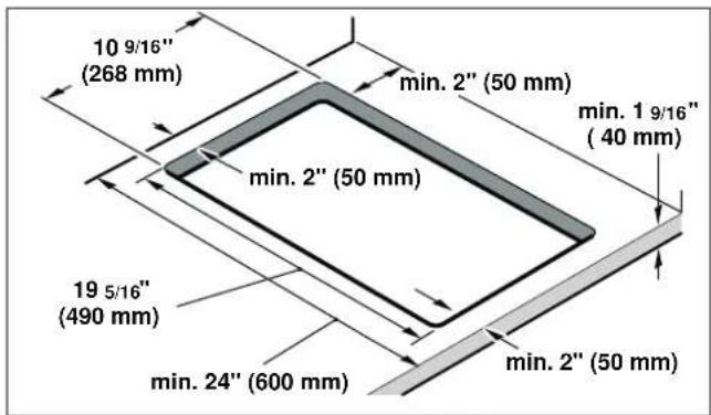
To reduce the risk of ignition of surrounding combustible materials, install at least 2" (51 mm) from both sidewalls and the rear wall.
The countertop must be level and horizontal. The stability of the countertop must be maintained after the cut-out has been made.
Installation Procedure
Prepare Installation Space
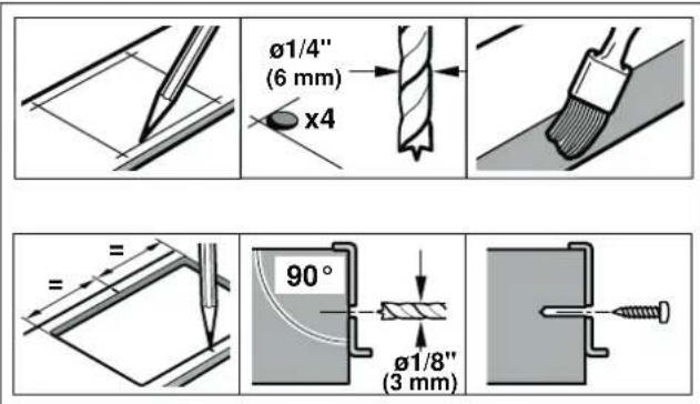
Create the cut-out in the countertop for one or several Vario appliances according to the installation diagram. The angle of the cut surface to the countertop must be 90°.
After creating cut-out, remove shavings. Seal cut surfaces in a heat-resistant manner.
Some solid surface countertops require special installations. For example, heat reflective tape and rounded corners may be necessary. Contact the countertop manufacturer for instructions specific to your countertop.
Observe minimum distance between appliance underside and furniture parts of 38 " (10 mm).
When installing multiple Vario appliances: Take into account space requirement for VV 200 connection strip between the appliances. Appliances can also be installed in individual cut-outs, bearing in mind a minimum distance between the appliances of 1^9 / 16'' (40 mm).
Install Appliance

WARNING
Before you plug in an electrical cord or turn on power supply, make sure all controls are in the OFF position.
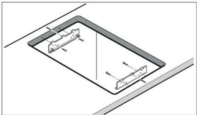
1 Make a mark exactly in the center of the cut-out. Fasten the mounting rails to the front and rear edge of the cut-out. The leading edges of the mounting rails must lie upon the countertop. The center marking of the mounting rails must correspond precisely with the center marking of the cut-out.
Note: For stone countertops, adhere the mounting rails with temperature-resistant duel-component adhesive (metal on stone).
natural_image
Technical diagram of a mechanical assembly with two rectangular components and alignment lines (no text or symbols)2 For combination with the VD 201 appliance cover: Mount appliance cover to appliance prior to installation (see VD 201 Installation Instructions).
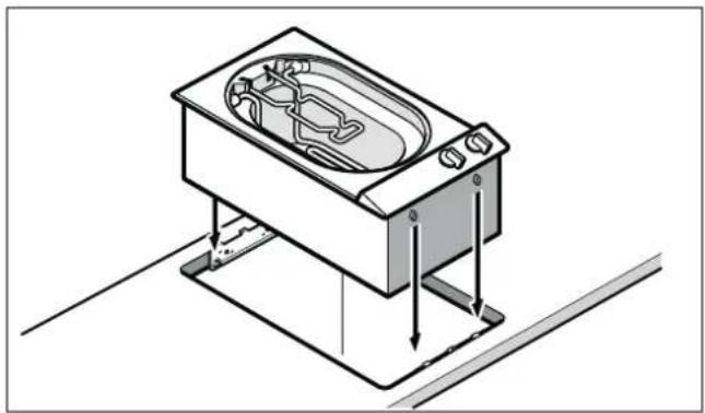
3 Insert appliance in cut-out. The snap-in pins on the appliance must lie precisely on the clamp springs. Press appliance firmly into the cut-out. The snap-in pins on the appliance must snap into the clamp springs.
natural_image
Isometric line drawing of a kitchen appliance with a lid and base, showing internal components and mounting base (no text or symbols)Connect Electrical Supply
Refer to data plate for more information. See "Service" for data plate location.
The branch-circuit breakers ampacity, the wire sizes and the connections must be conform to the requirements of the National Electrical Code or Canadian Electrical Code and all local codes and ordinances.
Attach flexible conduit to the junction box. Connect the lead wires to the junction box supply wires in proper phase:
- black (L1) to black
red (L2) to red - green to ground
The mains connecting cable must at least correspond to the type SJTO 3x16 AWG 105°C. The mains connecting cable must only be purchased through and connected by an authorised specialist.
Connection with a plug
- Plug has to be conform with NEMA CONFIGURATIONS FOR PLUGS AND RECEPTACLES.
● The appliance must be properly grounded. - Plug must be rated not less than type 6-20 P (2-pole 3-wire grounding).
- Only a qualified electrician should connect the plug.
- Install a socket outlet earthed in accordance with regulations approx. 27" (700 mm) above the floor behind the appliance. The socket outlet must still be accessible after installation.
Check the Installation
WARNING
Before you plug in an electrical cord or turn on power supply, make sure all controls are in the OFF position.
Remove everything from the cooktop surface. Clean cooktop surface with cooktop cleaning creme.
Switch on the circuit breaker.
Verify that elements function properly.
Removing appliance
Disconnect the appliance from the power supply. Push out the appliance from below.
CAUTION
Damage to appliance! Don't lift device out from above.
Customer service
If your appliance needs repairs, our customer service is there for you. We work hard to help solve problems quickly and without unnecessary service calls, getting your appliance back up and running correctly in the least amount of time possible.
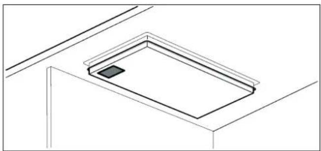
When you call, please indicate the product number (E-Nr.) and serial number (FD-Nr.) so that we can support you in a qualified manner. You will find the type plate with these numbers on the bottom of the appliance. To avoid having to search for a long time when you need it, you can enter your appliance data and the customer support telephone number here.
E-Nr. FD-Nr.
Customer Service
Please read the installation instructions and use and care instructions provided with your appliance. Failure to do so may result in an error in using the appliance. This could result in a service call that instead of fixing a mechanical issue is only needed for customer education. Such calls are not covered by the appliance warranty.
natural_image
Pure architectural line drawing of a rectangular structure with no text, numbers, or symbolsPlease find the contact data of all countries in the enclosed customer service list.
To book an engineer visit and product advice
USA 877 442 4436
toll-free
CANADA 800 828 9165
You can rely on the manufacturer's expertise. Rest assured that the repair will be handled by trained service technicians who have the original replacement parts for your appliance.
CONSIGNES DE SÉCURITÉ IMPORTANTES LIRE ET CONSERVER CES INSTRUCTIONS
INSTALLATEUR : LAISSEZ CES INSTRUCTIONS AVEC L'APPAREIL APRÈS UNE FOIS L'INSTALLATION TERMINÉE.
IMPORTANT : CONSERVER CES INSTRUCTIONS POUR L'USAGE DE L'INSPECTEUR ÉLECTRIQUE LOCAL.
AVERTISSEMENT
natural_image
Line drawing of a kitchen electrician with a basket, control panel, and screw base (no text or symbols)natural_image
Technical diagram of a rectangular frame with internal structural components and alignment lines (no text or symbols)natural_image
Isometric line drawing of a mechanical device with internal components and directional arrows (no text or symbols)natural_image
Isometric line drawing of a rectangular frame with a small square cutout, mounted on a vertical support (no text or symbols)natural_image
Line drawing of a kitchen electrician with a basket, screw base, and battery pack (no text or symbols)Requisitos de gabinetes
natural_image
Technical diagram of a mechanical assembly with two rectangular components and directional arrows, no visible text or symbolsnatural_image
Isometric line drawing of a washing machine with internal components and directional arrows (no text or symbols)natural_image
Isometric line drawing of a rectangular frame with a small square cutout, mounted on a support structure (no text or symbols)The reproduction, transmission or use of this document or its contests is not permitted without express written authority. Offenders will be liable for damages. All rights including rights created by patent grant or registration of a utility model or design are reserved. Copyright reserved.
Gaggenau
BSH Home Appliances Ltd.
1901 Main Street, Suite 600
Irvine, CA 92614
+1 877 4GAGGENAU
USA
www.gaggenau-usa.com
- IMPORTANT SAFETY INSTRUCTIONS
- READ AND SAVE THESE INSTRUCTIONS
- WARNING
- Appliance Handling Safety
- Safety Codes and Standards
- Electric Safety
- Risk of electrical shock or fire
- Related Equipment Safety
- State of California Proposition 65 Warnings
- Tools and Parts Needed
- Cabinet Requirements
- Notes
- Countertop Requirements
- Installation Procedure
- Prepare Installation Space
- Install Appliance
- Connect Electrical Supply
- Connection with a plug
- Check the Installation
- Removing appliance
- CAUTION
- Customer service
- E-Nr. FD-Nr.
- To book an engineer visit and product advice
- CONSIGNES DE SÉCURITÉ IMPORTANTES LIRE ET CONSERVER CES INSTRUCTIONS
- AVERTISSEMENT
- Requisitos de gabinetes
Brand : GAGGENAU
Model : VF230614
Category : Deep fryer