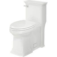
Town Square S 2851A105 - Toilet American Standard - Free user manual and instructions
Find the device manual for free Town Square S 2851A105 American Standard in PDF.


| Brand | American Standard |
| Model | Town Square S 2851A105 |
| Category | Toilet |
| Type | One-piece |
| Bowl shape | Elongated |
| Seat height (Right Height) | 419 mm (16.5 in) |
| Flush capacity | 1.28 gallons / 4.8 liters per flush |
| Weight | 45 kg (99 lb) |
| Dimensions (L x W x H) | 768 x 480 x 776 mm |
| Water supply | Cold water, connection at 95 mm (3.75 in) or 229 mm (9 in) from center |
| Material | Vitreous china |
| Seat included | Yes, elongated with lid |
| Flush system | Gravity |
| Fill valve | Fluidmaster (compatible) |
| Maintenance | Clean with water and mild soap, avoid chlorinated cleaners |
| Safety | Fragile product, handle with care |
| Common replacement parts | Wax ring, toilet bolts, bolt caps, flapper |
| Warranty | Limited lifetime warranty (contact manufacturer) |
| Customer service (USA) | 1-800-442-1902 |
| Customer service (Canada) | 1-800-387-0369 |
| Years of experience | Over 140 years |
Frequently Asked Questions - Town Square S 2851A105 American Standard
User questions about Town Square S 2851A105 American Standard
0 question about this device. Answer the ones you know or ask your own.
Ask a new question about this device
Download the instructions for your Toilet in PDF format for free! Find your manual Town Square S 2851A105 - American Standard and take your electronic device back in hand. On this page are published all the documents necessary for the use of your device. Town Square S 2851A105 by American Standard.
USER MANUAL Town Square S 2851A105 American Standard
INSTALLATION INSTRUCTIONS
BOULEVARD® - 1.28 gpf/4.8 Lpf One-Piece Toilet Model 2891 - Elongated Right Height® with Seat
TROPIC® - 1.28 gpf/4.8 Lpf One-Piece Toilet Model 2786 - Elongated Right Height® with Seat
TOWN SQUARE® - 1.28 gpf/4.8 Lpf One-Piece Toilet Model 2847 - Elongated Right Height® with Seat
TOWN SQUARE® S - 1.28 gpf/4.8 Lpf One-Piece Toilet Model 2851A - Elongated Right Height® with Seat

Thank you for selecting American Standard – the benchmark of fine quality for over 140 years. To ensure this product is installed properly, please read these instructions carefully before you begin. (Certain installations may require professional help.) Also be sure your installation conforms to local codes.
CAUTION: PRODUCT IS FRAGILE. TO AVOID BREAKAGE AND POSSIBLE INJURY HANDLE WITH CARE! NOTE: Pictures may not exactly define contour of china and components.
RECOMMENDED TOOLS AND MATERIALS
Regular Screwdriver Wax Ring/Gasket
Adjustable Wrench Flexible Supply Tube
Putty Knife Closet Bolts
Sealant Hacksaw
Carpenters Level Tape Measure
1 REMOVE OLD TOILET
a. Close toilet supply valve and flush tank completely. Towel or sponge remaining water from tank and bowl.
b. Disconnect and remove supply line. NOTE: If replacing valve, first shut off main water supply!
c. Remove old mounting hardware, remove toilet and plug floor waste opening to prevent escaping sewer gases.
d. Remove closet bolts from flange and clean away old wax, putty, etc. from base area.
NOTE: Mounting surface must be clean and level before new toilet is installed!
2 ROUGHING-IN DIMENSIONS:
NOTE: Distance from wall to closet flange centerline must be as listed below:
Model 2891 - BOULEVARD 1.28 gpf/ 4.8 Lpf
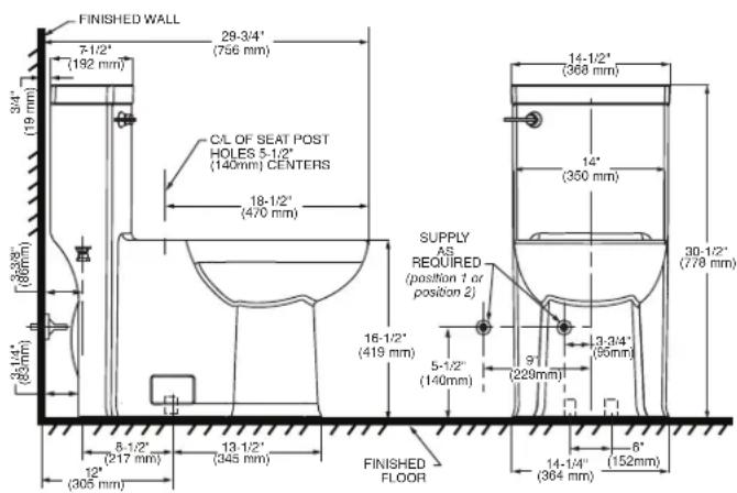
IMPORTANT: Water supply on the wall is required at 3-3/4" or 9" from centerline of the toilet (see rough-in). First suggested position is hidden behind the toilet. The geometry of the toilet gives space for this installation. The second suggested position is next to the toilet. Between these two positions, the space for the supply between wall and toilet is limited to 3-1/4". In this case, check your supply and hose dimensions.
Model 2786 - TROPIC 1.28 gpf/ 4.8 Lpf
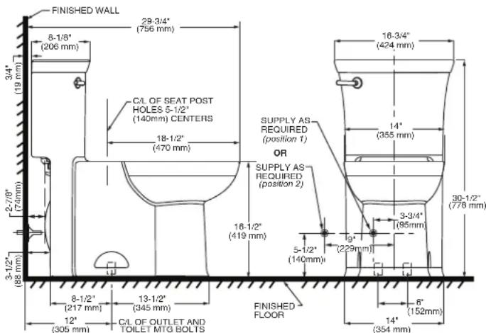
IMPORTANT: Water supply on the wall is required at 3-3/4" or 9" from centerline of the toilet (see rough-in). First suggested position is hidden behind the toilet. The geometry of the toilet gives space for this installation. The second suggested position is next to the toilet. Between these two positions, the space for the supply between wall and toilet is limited to 3-1/4". In this case, check your supply and hose dimensions.
2a
ROUGHING-IN DIMENSIONS:
NOTE: Distance from wall to closet flange centerline must be as listed below:
Model 2847 - TOWN SQUARE 1.28 gpf/ 4.8 Lpf Model 2851A - TOWN SQUARE S 1.28 gpf /4.8 Lpf
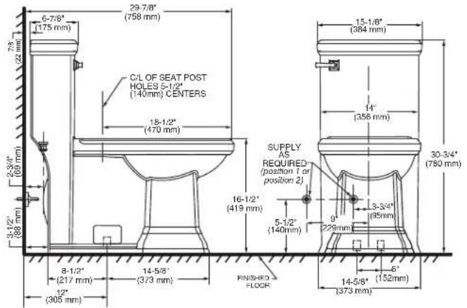

IMPORTANT: Water supply on the wall is required at 3-3/4" or 9" from centerline of the toilet (see rough-in). First suggested position is hidden behind the toilet. The geometry of the toilet gives space for this installation. The second suggested position is next to the toilet. Between these two positions, the space for the supply between wall and toilet is limited to 3-1/4". In this case, check your supply and hose dimensions.
3
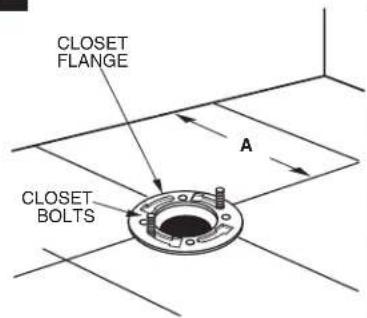
INSTALL CLOSET BOLTS
Install closet bolts in flange channel, turn 90°, and slide into place 6" (152mm) apart and parallel to wall.
4
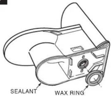
INSTALL WAX SEAL
Invert toilet on floor (cushion to prevent damage), and install wax ring evenly around waste flange (horn), with tapered end of ring facing toilet. Apply a thin bead of sealant around toilet base.
5
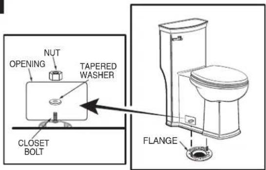
a. Unplug floor waste opening and install toilet on closet flange so bolts project through mounting holes.
b. Loosely install retainer washers and nuts. Side of washers marked "THIS SIDE UP" must face up!
6
INSTALL TOILET
a. Position toilet squarely to wall and, with a rocking motion, press bowl down fully on wax ring and flange.
Alternately tighten nuts until toilet is firmly seated on floor.

CAUTION: DO NOT OVERTIGHTEN NUTS OR BASE MAY BE DAMAGED!
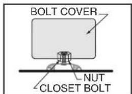
b. Install bolt covers:
- Make sure that the bolt cover area on the toilet is clean and dry (see figure). Use a dry piece of cloth or soap and water if needed.
- Take plastic bolt cover and peel the brown protective film off on both ends. The adhesive part is now visible and ready to be placed on the toilet (see figure).
- Gently place the bolt cover on the toilet area (see picture) and if everything is aligned, push bolt cover firmly so it remains in place.
- If not aligned, you can still take it off and put it back so it is aligned.
- Repeat Step 3 for second bolt cover which is to be placed on opposite side of the toilet.
- After 24 hours, the bolt cover adhesive has completely set off and if needed, you can remove/replace as needed. The dual lock technology is now in place.
c. Smooth off the bead of sealant around base. Remove excess sealant.

7
INSTALL TOILET SEAT Install toilet seat in accordance with manufacturer's directions.
8a
Before continuing, determine the type of water supply connection you have from the chart below and use the appropriate assembly parts required to properly reconnect the water supply. DO NOT use plumber's putty to seal these fittings.
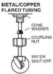
These parts must be used as illustrated to insure water-tight connection. Use of existing coupling nut may result in water leakage. Water supply tube or pipe must extend at least 1/2" inside threaded shank of valve (does not apply to flanged tubing).
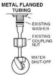
Use existing coupling nut and washer.
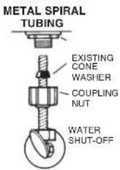
Use existing spiral cone washer. Fluidmaster cone washer may not seal completely on spiral type supply line.
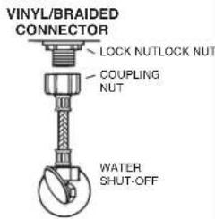
Captive cone washers already included. No additional washers needed.
CAUTION: DO NOT USE CONE WASHER WITH PLASTIC SUPPLY LINE.
CAUTION: Overtightening of LOCK NUT or COUPLING NUT could result in breakage and potential flooding.
8b
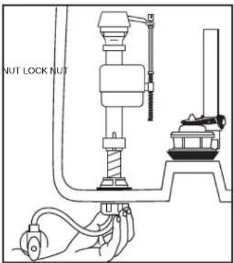
With correct washers in place (see Step 8a), tighten COUPLING NUT 1/4 turn beyond hand tight.
DO NOT OVERTIGHTEN.
9
ADJUSTMENTS
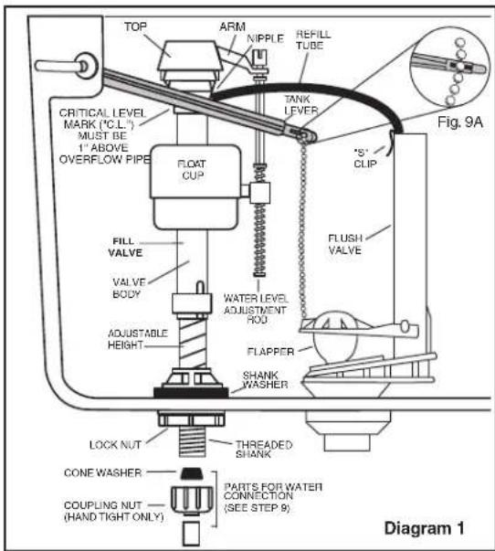
a. Adjust water level. Water level should be adjusted to level indicated on tank by adjusting float cup.
See Step 10 for water level adjustment method.
b. If bowl fails to siphon, an adjustment may be required with the lift chain. Simply remove the bead chain from the retainment clip (see Fig. 9A) and take up slack on the chain, and reinsert on lift rod. Make sure the chain is not too taught.
10
natural_image
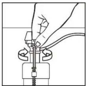
Illustration of a hand adjusting a mechanical component with a spring and connecting rod (no text or symbols)Turn on water supply. Submerge the FLOAT CUP under the water for 30 seconds. Adjust the water to desired level by turning WATER LEVEL ADJUSTMENT ROD and moving FLOAT CUP up or down.
11
CARE AND CLEANING
When cleaning your toilet, wash it with mild, soapy water, rinse thoroughly with clear water and dry with a soft cloth. Avoid detergents, disinfectants, or cleaning products in aerosol cans. NEVER use abrasive scouring powders or abrasive pads on your toilet seat. Some bathroom chemicals and cosmetics may damage the seat's finish.

WARNING: Do not use in-tank cleaners. Products containing chlorine (calcium hypochlorite) can seriously damage fittings in the tank. This damage can cause leakage and property damage. American Standard shall not be responsible or liable for any tank fitting damage caused by the use of cleaners containing chlorine (calcium hypochlorite).
12
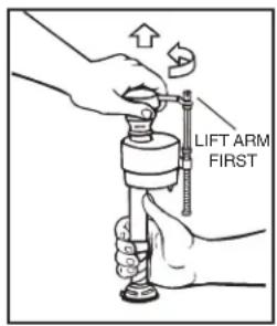
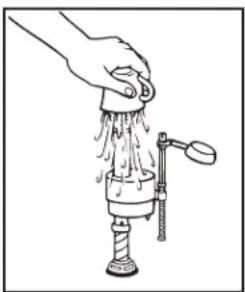
IMPORTANT: Always clear sand and rust from system.
- Make sure water supply is off. Remove valve TOP by lifting arm and rotating top and arm 1/8 turn counterclockwise, pressing down slightly on cap.
natural_image
Line drawing of a hand cleaning a faucet with water spray (no text or symbols)- While holding a container over the uncapped VALVE to prevent splashing, turn water supply on and off a few times. Leave water supply off.
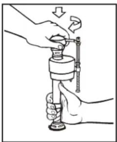
natural_image
Illustration of hands using a mechanical tool to adjust or install a component (no text or symbols visible)- Replace TOP by engaging lugs and rotating 1/8 turn clockwise. MAKE CERTAIN TIP IS TURNED TO THE LOCKED POSITION. VALVE MAY NOT TURN ON IF TOP IS NOT FULLY TURNED TO THE LOCKED POSITION.
Always use quality Fluidmaster repair parts when maintaining your Fluidmaster products. Fluidmaster shall not be responsible or liable for any damages caused by products used with Fluidmaster valves that were not manufactured by Fluidmaster, Inc.
TROUBLESHOOTING
IF FILL VALVE SHUTS OFF BUT CONTINUES TO LEAK SLOWLY, repeat Step 12.
IF FILL VALVE TURNS OFF AND ON DURING PERIODS OF NON-USE, it is a signal you are wasting water because:
- The end of the refill tube is inserted into overflow pipe, below water level in tank. Attach refill tube to overflow pipe using "S" clip provided.
- The flush valve is leaking because it's worn, dirty or misaligned with tank ball or flapper (replace with a new flapper).
IF FILL VALVE WON'T TURN ON OR SHUT OFF or REFILL OF TANK WATER IS SLOW after valve has been in use for some time, Fluidmaster Model 242 Replacement Seal may be needed.
Go to our website at www.fluidmaster.com for more solutions to toilet problems.
For troubleshooting information please contact:
FluidmasterInc
30800 Rancho Viejo Road
San Juan Capistrano, CA 92675
(949) 728-2000 (800) 631-2011
www.fluidmaster.com
© 2001 Fluidmaster, Inc. ® Registered trademark of Fluidmaster, Inc.
| TROUBLESHOOTING GUIDE | ||
| PROBLEM POSSIBLE CA | USE CORRECTIVE ACTION | |
| Does not flush | a. Water supply valve closed. | a. Open valve and allow water to fill tank. |
| b. Supply line blocked. | b. Shut off water supply, disconnect supply line and inspect all gaskets and washers. Reassemble. Also, see Fluidmaster maintenance. (see Step 12) | |
| c. Flush valve chain too loose or disconnected. | c. Readjust chain length as required. | |
| d. Sand or debris lodged in water control. | d. Shut off water supply. Remove cap and clean as per Step 12. | |
| Poor or sluggish flush | a. Bowl water level too low. | a. Check that refill tube is connected to water control and inserted into tank overflow without being kinked or damaged. |
| b. Supply valve partly closed. | b. Open supply valve fully. Be sure that proper supply tube size is used. | |
| c. Partially clogged trapway and/or drain pipe and/or vent. | c. Remove obstruction. Consult a plumber if necessary. | |
| d. Supply pressure too low. | d. Normal supply pressure must be at least 20 psi. | |
| e. Flush valve chain too tight, holding flush valve open. | e. Readjust chain length as needed. Review Step 9A. | |
| Toilet leaks | a. Poor supply line connection. | a. Review Step 8a and 8b of installation procedure. |
| b. Poor bowl to tank/floor connection. | b. Review Step 4 through 6 of installation procedure. | |
| Toilet does not shut off | a. Flush valve seal leaking or deformed. | a. Clean debris from seal surface. Replace flush valve seal as needed. |
| b. Sand or debris lodged in water control. | b. Shut off water supply. Remove cap and clean as per Step 12. | |
In the United States:
American Standard Brands
1 Centennial Ave
Piscataway, New Jersey 08854
Attention: Director of Customer Care
For residents of the United States, warranty information may also be obtained by calling the following toll free number: (800) 442-1902
www.americanstandard.com
In Canada:
AS Canada, ULC
5900 Avebury Rd.
Mississauga, Ontario
Canada L5R 3M3
Toll Free: (800) 387-0369
www.americanstandard.ca
In Mexico:
American Standard B&K Mexico
S. de R.L. de C.V.
Via Morelos #330
Col. Santa Clara
Ecatepec 55540 Edo. Mexico
Toll Free: 01-800-839-1200
www.americanstandard.com.mx
natural_image
Technical line drawing of a mechanical device with no visible text or symbolsnatural_image
Line drawing of hands connecting a mechanical component to a wire (no text or symbols)natural_image
Line drawing of a hand cleaning a faucet with water spray (no text or symbols)natural_image
Illustration of hands using a mechanical tool to adjust a cylindrical component (no text or symbols visible)© 2001 Fluidmaster, Inc.
© Marca comercial registrada de Fluidmaster, Inc.
American Standard Brands
1 Centennial Ave
Piscataway, New Jersey 08854
American Standard B&K México
S. de R. L. de C.V.
Vía Morelos #330
Col. Santa Clara
Ecatepec 55540 Edo. México
www.americanstandard.com.mx
INSTRUCTIONS D'INSTALLATION
natural_image
Illustration of hands connecting a mechanical component to a spring-loaded assembly (no text or symbols visible)natural_image
Line drawing of a hand using a faucet to lift water, with no text or symbols present.natural_image
Illustration of hands using a mechanical tool to adjust or install a cylindrical component (no text or symbols visible)© 2001 Fluidmaster, Inc.
American Standard Brands
1 Centennial Ave
Piscataway, New Jersey 08854
www.americanstandard.com.mx


- INSTALLATION INSTRUCTIONS
- RECOMMENDED TOOLS AND MATERIALS
- REMOVE OLD TOILET
- ROUGHING-IN DIMENSIONS:
- ROUGHING-IN DIMENSIONS:
- INSTALL TOILET
- CAUTION: DO NOT OVERTIGHTEN NUTS OR BASE MAY BE DAMAGED!
- ADJUSTMENTS
- CARE AND CLEANING
- TROUBLESHOOTING
- FluidmasterInc
- In the United States:
- In Canada:
- In Mexico:
- INSTRUCTIONS D'INSTALLATION
Brand : American Standard
Model : Town Square S 2851A105
Category : Toilet