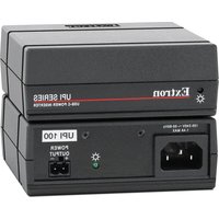
UPI 100 - Electronic accessory Extron - Free user manual and instructions
Find the device manual for free UPI 100 Extron in PDF.


| Product type | Electronic accessory / Power supply |
| Brand | Extron |
| Model | UPI 100 |
| Power input | 100-240 V AC, 50/60 Hz |
| Power consumption | Not specified but suitable for AV equipment |
| Protection | Class 1 with grounding |
| Mounting | Non-permanent via ZipClip bracket |
| Usage | On a flat surface, not in wall cavities or ventilation spaces |
| Operating temperature | 0 to 40 °C (estimated) |
| Relative humidity | 20 to 80% non-condensing (estimated) |
| Enclosure material | Flame-retardant plastic (estimated) |
| Color | Black (estimated) |
| Certifications | CE, UL, FCC (estimated) |
| Package contents | UPI 100 unit, power cord, ZipClip bracket, documentation |
| Warranty | Standard manufacturer warranty |
| Maintenance | Clean with a dry, lint-free cloth |
| Spare parts | Power cords and brackets available |
| Repairability | Contact a qualified technician. No user-serviceable parts. |
Frequently Asked Questions - UPI 100 Extron
User questions about UPI 100 Extron
0 question about this device. Answer the ones you know or ask your own.
Ask a new question about this device
Download the instructions for your Electronic accessory in PDF format for free! Find your manual UPI 100 - Extron and take your electronic device back in hand. On this page are published all the documents necessary for the use of your device. UPI 100 by Extron.
USER MANUAL UPI 100 Extron
UPI 100 USB-C® Power Inserter • Installation Guide
IMPORTANT NOTE:
Go to www.extron.com for the complete UPI 100 specifications before connecting the product to the power source.

Important Safety Instructions

This symbol is intended to alert the user of important operating and maintenance (servicing) instructions in the literature provided with the equipment.

This symbol is intended to alert the user of the presence of uninsulated dangerous voltage within the product enclosure that may present a risk of electric shock. On the product, risk of shock may be indicated by this symbol.
Read these instructions.
Keep these instructions.
Heed all warnings.
Follow all instructions.
Do not use this apparatus near water.
Clean only with dry cloth.
Do not block any ventilation openings. Install in accordance with the manufacturer's instructions.
Do not install near any heat sources such as radiators, heat registers, sloves, or other apparatus (including amplifiers) that produce heat.
Do not defeat the safety purpose of the polarized or grounding-type plug. A polarized plug has two blades with one wider than the other. A grounding type plug has two blades and a third grounding prong. The wide blade or the third prong are provided for your safety. If the provided plug does not fit into your outlet, consult an electrician for replacement of the obsolete outlet.
Protect the power cord from being walked on or pinched particularly at plugs, convenience receptacles, and the point where they exit from the apparatus.
Only use attachments/accessories specified by the manufacturer.
Unplug this device app aratus during lightning storms or when unused for long periods of time.
CAUTION:
ACTION: To reduce the risk of fire or electric shock, do not expose this apparatus to rain or moisture. This apparatus shall not be exposed to dripping or splashing and no objects filled with liquids, such as vases shall be placed on the apparatus.
ATTENTION
Refer all servicing to qualified service personnel. Servicing is required when the apparatus has been damaged in any way, such as when the power-supply cord or plug is damaged, liquid has been spilled or objects have fallen into the apparatus, the apparatus has been exposed to rain or moisture, does not operate normally, or has been dropped.
CAUTION:
AUTION: This apparatus is a Class I product. This product must be connected to a mains socket outlet with a protective earthing connection.
ATTENTION
The mains plug is used as the disconnect device and shall remain readily operable.
To prevent the risk of shock, do not attempt to service this equipment yourself because opening or removing covers may expose you to dangerous voltage or other hazards.
CAUTION:
- Power sources — This equipment should be operated only from the power source indicated on the product. This equipment is intended to be used with a main power system with a grounded (neutral) conductor. The third (grounding) pin is a safety feature, do not attempt to bypass or disable it.
• Power disconnection — To remove power from the equipment safely, remove all power cords from the rear of the equipment or from the power source receptacle (wall plug).
ATTENTION :
The Extron UPI 100 USB-C Power Inserter provides power to Extron products that support USB Type-C® connections. This allows up to 100 watts of power to be delivered to both the Extron device and a device such as a host laptop that is connected to it.
The UPI supplies power to the connected Extron product, which, in turn, converts the voltage to the USB-C standard for USB-C power delivery.
| Model Power | Output Termination | |
| UPI 100 Up to | 100 watts of power delivery to the Extron USB-C endpoint | 2-pole, 5 mm captive screw |
| ZipClip® 200 (included) | — | — |
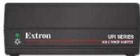
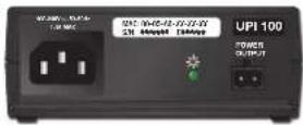
FrontRear
This guide provides instructions for an experienced installer to install a UPI power inserter and perform basic troubleshooting.
Features

UPI 100 • Installation Guide (Continued)
Installation
Determine the appropriate cable guage and length for your installation and system requirements. Then connect the devices according to the requirements and best practices recommendations noted in this section.
Cable Requirements
Extron recommends the following:
- The installation must meet all regulatory requirements for your region and comply with all applicable local and national safety, electrical codes and standards.
- The installation must meet all regulatory requirements for your region and comply with all applicable local and national safety, electrical codes and standards.
- L'installation doit répondre à toutes les exigences réglementaires de votre région et être conforme à tous les codes et normes de sécurité et électriques locaux et nationaux applicables.
- To determine the combination of cable guage and cable lengths for the connection between the UPI 100 and Extron product providing USB-C power delivery to the laptop, see the table below and see the specifications in the UPI 100 product page at www.extron.com.
| Conductor Gauge | Max. Recommended Cable Length | |
| 60 Watt Output 100 Watt Output | ||
| 12 AWG 33 | 0 feet (100 m) 80 feet (24 m) | |
| 14 AWG 22 | 0 feet (67 m) 50 feet (15 m) | |
| 16 AWG 14 | 0 feet (43 m) 30 feet (9 m) | |
| 18 AWG 85 | 0 feet (26 m) 20 feet (6 m) | |
Connector Wiring
Once you determine the correct guage and cable length for your installation, terminate the cables as shown in the following diagram.


5 mm
Captive
Screw
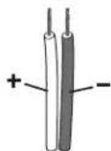
Power Output Cable
Cable Termination

5 mm Captive Screw Connector
5 mm Captive Screw Connector
Figure 1. Wiring the Power Output Cable
Installation Details and Diagram
Diagram
The following diagram provides an example of how to cable the UPI Series power inserter to Extron products that provide a USB-C connection.
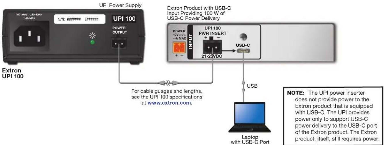
Figure 3. A UPI Supplying Power to a Product with 100 W Output on USB-C
Connections
In each system:
- Connect the UPI Power Output port to the UPI power insertion port on the rear panel of the other Extron product. See Connector Wiring on page 2 and the diagram in figure 2, for details.
- Connect the AC power mains to the power input connector on the UPI.
- Connect an external device such as a laptop to the USB-C port on the Extron product.
Troubleshooting and Fault Status Indications
If the speaker wire cable connected to the UPI is too long or power level configured for the connected Extron product is incorrect, a fault condition can develop in the system. See the user guide for the connected Extron product to learn about fault status indication.
Using the ZipClip 200
Attaching and Removing the Clip and UPI
To attach the power supply to the ZipClip 200 mounting clip:
- Insert the bottom of the power supply down into the clip, starting with one end.
- Pivot the other end down and press until the clip snaps into place.
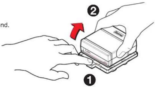
To remove the power supply from the ZipClip:
- Press the tab on the ZipClip (see ① at right).
- Pivot the UPI and lift it out of the ZipClip (see ②).
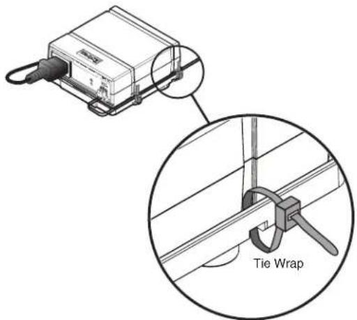
Using Tie Wraps for Cable Strain Relief
- Attach the UPI to the ZipClip 200 mounting clip as described previously.
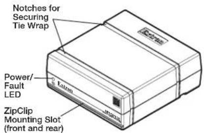
- Fasten the power output cord to the ZipClip base.
a. Insert tie wraps (which are also called "zip ties") along the notches on the side of the UPI and through the tie wrap anchor points on the ZipClip, then around the cord.
b. Connect and pull the tie wraps until they are secure. Do not over tighten.
UPI 100 • Installation Guide (Continued)
Mounting
CAUTION: This power supply is not suitable for use in air handling spaces or in wall cavities. The ZipClip mounting bracket allows for non-permanent mounting.
- The installation must meet all regulatory requirements for your region and comply with all applicable local and National safety, electrical codes and standards.
Securely mount the UPI power inserter and other devices, and attach cables using Connector Wiring on page 2 and application diagrams (see Installation Details and Diagram on page 2) as a wiring guide. Optional 1U rack shelves are available from Extron. See the product-specific page at www.extron.com for a list of compatible accessories. Read the instructions and UL guidelines that come with the rack shelf or mounting kit for installation procedures.
The UPI comes with a ZipClip 200 mounting bracket, which can be mounted to the following items:
- Tabletop • Equipment rack rails
- Optional equipment rack shelf • Furniture
Rack Mounting
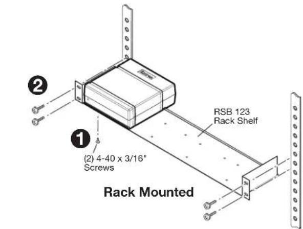
Mounting to a rack shelf
The UPI units are one quarter rack wide. Up to four units can be mounted side by side directly onto a rack shelf.
- Align the threaded holes in the bottom of the UPI with the holes in an Extron rack shelf and fasten the unit to the shelf with two 4-40 x 3/16 inch screws (see ① at right).
- Bolt the rack shelf to the rack ( ②).
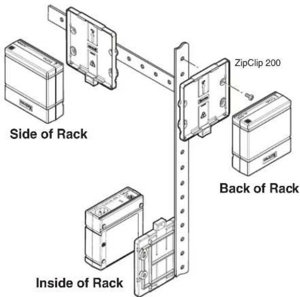
Mounting to rack rails using a ZipClip
- Fasten the ZipClip 200 mounting clip to a rack rail using two rack screws as shown in the diagram below.
- Insert the bottom of the unit down into the clip, starting with one end.
- Pivot the other end toward the clip and press until the clip snaps into place.
Furniture Mounting
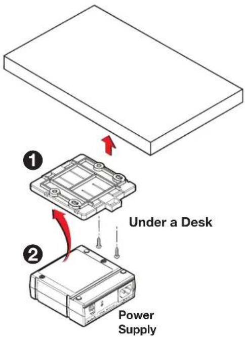
NOTE: The ZipClip is shipped with a set of four wood screws.
- Attach the ZipClip to the mounting surface using two or more wood screws (see ① at right). Make sure the clip is oriented with the appropriate side facing the mounting surface of the furniture and with the tab accessible from the front of the furniture.
- Insert the UPI into the ZipClip (②) as described previously and press to snap it into place.
Pole Mounting
Mounting the UPI to a projector mount pole requires an optional Extron PMK Series Pole Mount kit. Follow the installation instructions included with the mounting kit.
Safety Instructions
Safety Instructions • English

This symbol is intended to alert the user of important operating and maintenance (servicing) instructions in the literature provided with the equipment.

This symbol is intended to alert the user of the presence of uninsulated dangerous voltage within the product enclosure that may present a risk of electric shock.
Cautions and General Guidelines
Read instructions — Read and understand all safety and operating instructions before using the equipment.
Retain Instructions • The safety instructions should be kept for future reference.
Follow warnings — Follow all warnings and instructions marked on the equipment or in the user information.
Avoid attachments — Do not use tools or attachments that are not recommended by the equipment manufacturer because they may be hazardous.
Avoid water — Do not use this or other electrical equipment near water. Clean the device with a dry cloth only.
Warnings
Power and electrical safety
CAUTION:
- To reduce the risk of fire or electric shock, do not expose this apparatus to rain or moisture. This apparatus shall not be exposed to dripping or splashing and no objects filled with liquids, such as vases shall be placed on the apparatus.
- The power inserter is a Class I product, which must be connected only to a mains socket outlet with a protective earthing (grounding) connection.
ATTENTION :
- Power sources — This equipment should be operated only from the power source indicated on the product. This equipment is intended to be used with a main power system with a grounded (neutral) conductor. The third (grounding) pin is a safety feature, do not attempt to bypass or disable it.
• Power disconnection — To remove power from the equipment safely, remove all power cords from the rear of the equipment or from the power source receptacle (wall plug).
ATTENTION :
Power plug as a disconnection device — The mains plug is used as the disconnect device and shall remain readily operable. In other words, it the power plug must be accessible and easy to unplug from the power source.
When to unplug the unit — Unplug this device during lightning storms or when it will be unused for long periods. Unplug the device before servicing.
Power cord protection — Power cords should be routed so that they are not likely to be slipped on or pinched by items placed upon or against them. Protect the cord particularly at plugs, convenience receptacles, and the points where they exit the devices.
Polarized and grounding plugs — Do not defeat the safety purpose of the polarized or grounding type plug. A polarized plug has two blades with one wider than the other. A grounding type plug has two blades and a third grounding prong. The wide blade or the third prong are provided for your safety. If the provided plug does not fit into your outlet, consult an electrician to replace the obsolete outlet with a safer one.
Servicing — Refer all servicing to qualified service personnel. Servicing is required when the apparatus has been damaged in any way, such as when the power-supply cord or plug is damaged, liquid has been spilled into or objects have fallen into the device, or when the device has been exposed to rain or moisture, does not operate normally, or has been dropped. To prevent the risk of shock, do not attempt to service this equipment yourself because opening or removing covers may expose you to dangerous voltage or other hazards.
Ventilation, mounting, and temperature
Ventilation slots and openings — If the equipment has slots or holes in the enclosure, these are provided to prevent overheating of
sensitive components inside. Do not block any ventilation opening, as this may cause the product to malfunction. Install the device in accordance with the manufacturer's instructions.
Temperature — Do not install electronic devices near any heat sources such as radiators, heat registers, stoves, or other apparatus (including amplifiers) that produce heat.
UPI 100 • Installation Guide (Continued)
安全须知·中文
Use only in non-tropical conditions.
This equipment has been tested and found to comply with the limits for a Class A digital device, pursuant to part 15 of the FCC rules. The Class A limits provide reasonable protection against harmful interference when the equipment is operated in a commercial environment. This equipment generates, uses, and can radiate radio frequency energy and, if not installed and used in accordance with the instruction manual, may cause harmful interference to radio communications. Operation of this equipment in a residential area is likely to cause interference. This interference must be corrected at the expense of the user.
For information on safety guidelines, regulatory compliances, EMI/EMF compatibility, accessibility, and related topics, see the Extron Safety and Regulatory Compliance Guide on the Extron website.
- UPI 100 USB-C® Power Inserter • Installation Guide
- IMPORTANT NOTE:
- Important Safety Instructions
- CAUTION:
- ATTENTION
- ATTENTION :
- Features
- UPI 100 • Installation Guide (Continued)
- Installation
- Cable Requirements
- Connector Wiring
- Installation Details and Diagram
- Diagram
- Connections
- Troubleshooting and Fault Status Indications
- Using the ZipClip 200
- Attaching and Removing the Clip and UPI
- Using Tie Wraps for Cable Strain Relief
- Mounting
- Rack Mounting
- Mounting to a rack shelf
- Mounting to rack rails using a ZipClip
- Furniture Mounting
- Pole Mounting
- Safety Instructions
- Safety Instructions • English
- Cautions and General Guidelines
- Warnings
- Power and electrical safety
- Ventilation, mounting, and temperature
- 安全须知·中文
Brand : Extron
Model : UPI 100
Category : Electronic accessory