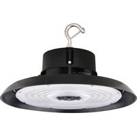
65/782 - Lighting NUVO - Free user manual and instructions
Find the device manual for free 65/782 NUVO in PDF.


| Product Type | LED High Bay Luminaire |
| Brand | NUVO |
| Model | 65/782 |
| Power Supply | 0-10 V standard dimming |
| Mounting | Hook or ceiling, vertical tilt 50° left or right |
| Motion Detector | Optional, CC (ref. 86/218), requires remote control 86/219 |
| Max. Mounting Height (detector) | 12 meters (39 feet 4 inches) |
| Power Cable | Non-replaceable, non-modifiable |
| Terminal Block | Not included, to be provided by the installer |
| Safety | Disconnect before installation/maintenance; installation by qualified personnel only |
| Maintenance and Cleaning | Clean with a dry, non-abrasive cloth; do not use solvents |
| Spare Parts and Repairability | Do not disassemble without authorization; if cable is damaged, destroy the luminaire |
| Included Accessories | Mounting hook, mounting screws (not detailed) |
| Wiring Instructions | Follow provided diagram; for dimming, cut the dimming cable from the CC sensor port |
| Warranty | Not specified |
Frequently Asked Questions - 65/782 NUVO
User questions about 65/782 NUVO
0 question about this device. Answer the ones you know or ask your own.
Ask a new question about this device
Download the instructions for your Lighting in PDF format for free! Find your manual 65/782 - NUVO and take your electronic device back in hand. On this page are published all the documents necessary for the use of your device. 65/782 by NUVO.
USER MANUAL 65/782 NUVO
INSTALLATION AND SAFETY INSTRUCTIONS
IMPORTANT: Read before installing fixture. Retain for future reference.
WARNING: Risk of Fire or Electric Shock
- To avoid damage, falling, electric shock or fire, do not modify the lamp or replace accessories without confirming with the supplier first.
- Only authorized, qualified personnel should install this fixture and should follow the owner's manual. Any improper installation might cause failure, electric shock, fire or other injury, damage or hazard.
- Disconnect power before installation or any maintenance of the fixture.
- Do not dismantle the fixture without the supplier’s authorization.
- Do not touch the power supply when the fixture is operating.
- The external flexible cable or cord of this fixture cannot be replaced; if the cord is damaged, the fixture shall be destroyed.
- Terminal block not included. The electrical fitting must be installed by a licensed electrician.
- For use in environments where an accumulation of non-conductive dust on the fixture may be expected.
IMPORTANT: This product must be installed in accordance with the applicable installation code by a person familiar with the construction and operation of the product and the hazards involved.
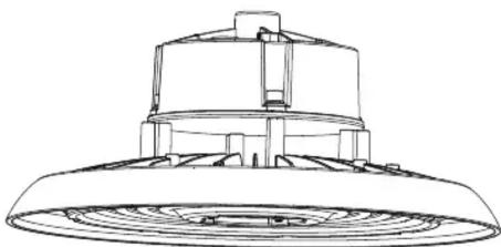
natural_image
Technical line drawing of a ceiling-mounted air vent (no text or symbols)65-781, 65-782, 65-783, 65-784,
65-791, 65-792, 65-793, 65-794,
65-801, 65-802, 65-803, 65-804:
∅11 13/6" (300mm)
65-784, 65-785, 65-787, 65-788,
65-795, 65-796, 65-797, 65-798,
65-805, 65-806, 65-807, 65-808:
∅14 3/16" (360mm)
SPECIFICATIONS
| Model CCT Volts CRI | Operating Temperature | ||
| 65-781 4000K | 100-277V 80 | -40°C to +45°C (-40°F to +113°F) | |
| 65-782 5000K | |||
| 65-783 4000K | |||
| 65-784 5000K | |||
| 65-785 4000K | |||
| 65-786 5000K | |||
| 65-787 4000K | |||
| 65-788 5000K | |||
| 65-791 4000K | |||
| 65-792 5000K | |||
| 65-793 4000K | |||
| 65-794 5000K | |||
| Model CCT Volts CRI | Operating Temperature | |||
| 65-795 4000K 120-277V | 80 | - 40^ C to + 45^ C (-40^ F to + 113^ F) | ||
| 65-796 5000K 120-277V | ||||
| 65-797 4000K 120-277V | ||||
| 65-798 5000K 120-277V | ||||
| 65-801 4000K 200-480V | ||||
| 65-802 5000K 200-480V | ||||
| 65-803 4000K 200-480V | ||||
| 65-804 5000K 200-480V | ||||
| 65-805 4000K 200-480V | ||||
| 65-806 5000K 200-480V | ||||
| 65-807 4000K 200-480V | ||||
| 65-808 5000K 200-480V |
WIRING DIAGRAM & INSTRUCTIONS
The LED high bay light can be equipped with an optional DC motion sensor (86/218). The sensor needs to be set via remote (86/219). For standard 0-10V dimming applications, the dimming cable must be cut free from the integrated DC sensor port.
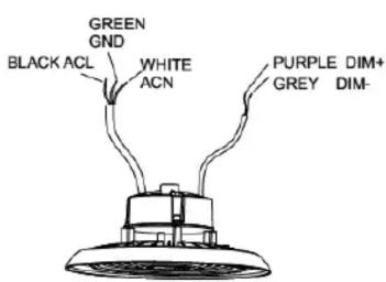
A
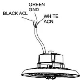
B: Motion Sensor
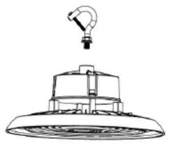
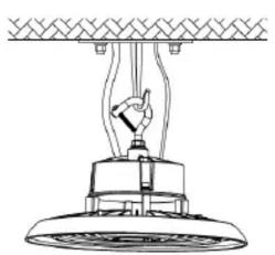
INSTALLATION: Hook Mount
STEP 1: Screw the hook into the fixture, tighten and secure.
natural_image
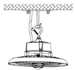
Line drawing of a ceiling-mounted industrial lamp with a handle and base (no text or symbols)STEP 3: Connect wires using the wiring diagram and instructions on page 1. Make sure connections are capped and sealed.
STEP 2: Hang the fixture on the ceiling hook or chain.
natural_image
Technical line drawing of a mechanical assembly with a lever and base mount (no text or symbols)A B: Motion Sensor
natural_image
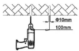
Technical line drawing of a ceiling-mounted air vent with a hand adjusting the valve (no text or symbols)INSTALLATION: Ceiling Mount
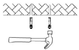
STEP 1: Use a pen or sharp tool and mark holes through the mounting surface on the ceiling and drill holes. Fix screws into the holes with a hammer.
natural_image
Illustration of a hammer and a brick wall with two hanging fixtures (no text or symbols)STEP 3: Connect wires using the wiring diagram and instructions on page 1. Make sure connections are capped and sealed.
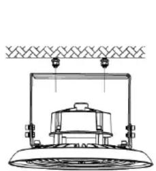
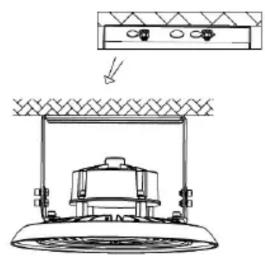
STEP 2: Align the bracket hole with screw hole and push the fixture to one side and secure.
natural_image
Technical line drawing of a mechanical device with no visible text or symbolsNOTE: By adjusting the bracket screws, the fixture can be angled 50^ to the left or right vertically.
natural_image
Technical line drawing of a mechanical assembly with a base mount and mounting bracket (no text or symbols)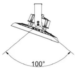
Optional DC Motion Sensor
Motion sensor installation does not require tools.
NOTE: The motion sensor has no dialing code. A remote control (86/219) is needed for adjustment. Refer to remote control instructions for adjustments. Maximum mounting height for sensor is 39 feet, 4 inches (12 meters).
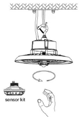
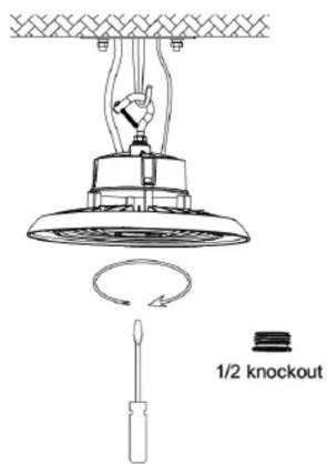
If motion sensor is not desired, unscrew the motion sensor and replace it with a protective cover.

Satco Products, Inc.
Brentwood, NY 11717© Copyright 2020 Sa
ESPAÑOL:
Brand : NUVO
Model : 65/782
Category : Lighting