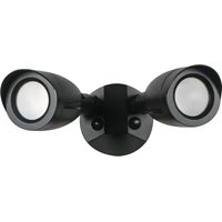
65/720 - Lighting NUVO - Free user manual and instructions
Find the device manual for free 65/720 NUVO in PDF.


| Product type | LED outdoor luminaire |
| Models concerned | 65/720 (base) and models with motion detector: 65/711, 65/713, 65/715, 65/717, 65/719, 65/721 |
| Power supply | Direct electrical connection (voltage per luminaire label) |
| Main functions | Adjustable LED lighting, optional motion detector, photocell |
| Installation | Wall mounting (external or built-in junction box) or ceiling mounting |
| Head orientation | Adjustable heads (minimum 20° below horizontal to avoid water accumulation) |
| Supplied accessories | Optional visors (not included), connection caps |
| Maintenance and cleaning | Clean the lens with a non-abrasive solution; do not open to clean the LED |
| Safety | Disconnect power before any intervention; installation by a qualified electrician; mandatory grounding |
| Waterproofing | Apply silicone sealant on joints and junction box |
| Repairability | Non-replaceable LED; spare parts not specified |
| Warranty | Not specified |
Frequently Asked Questions - 65/720 NUVO
User questions about 65/720 NUVO
0 question about this device. Answer the ones you know or ask your own.
Ask a new question about this device
Download the instructions for your Lighting in PDF format for free! Find your manual 65/720 - NUVO and take your electronic device back in hand. On this page are published all the documents necessary for the use of your device. 65/720 by NUVO.
USER MANUAL 65/720 NUVO
INSTALLATION AND SAFETY INSTRUCTIONS
IMPORTANT: Read before installing fixture. Retain for future reference.
WARNING: Risk of Fire or Electric Shock
- Commercial installation, service and maintenance of luminaries should be performed by a qualified licensed electrician. If you are unsure about the installation or maintenance of the luminaries, consult a qualified licensed electrician and check your local electrical code.
- Turn OFF power at fuse or circuit breaker before wiring fixture to power supply.
- Turn OFF power when you perform any maintenance.
- Verify that supply voltage is correct by comparing it with the luminaire label.
- Risk of Burn. Disconnect power and allow fixture to cool before handling.
- Clean glass lens with non-abrasive glass cleaning solution.
- Do not open fixture to clean the LED. Do not touch the LED.
WIRING: If wiring does not include a ground wire, consult your local electrical code for approved grounding methods. For proper connection, place wire nut over wires and twist clockwise until tight.
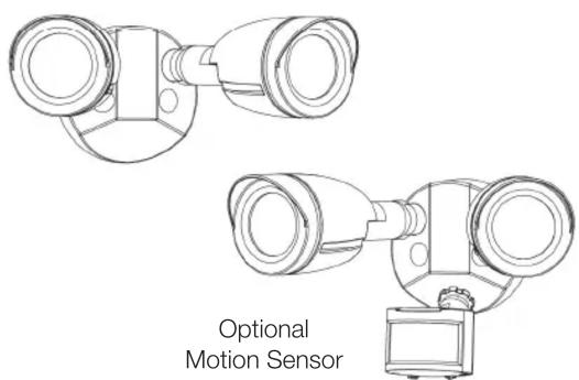
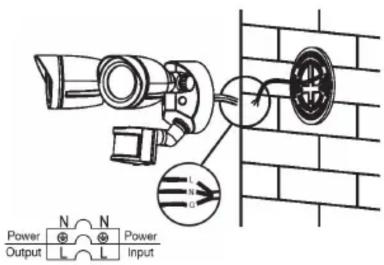
- Connect supply wires. Use wire nut to connect the black fixture wire to the black power supply wire and the white fixture wire to the white (neutral) supply wire. NOTE: Lamp heads must be positioned above motion sensor head and controls on motion sensor must face the ground.
- Aim lamp heads and install optional visors. Loosen knobs and aim lamp heads. CAUTION: Risk of Shock: Aim lamp heads at least 20^ down below horizontal in order to prevent water from accumulating inside lens. After lamp heads are positioned as desired, align the optional visor over the front of the lamp head and secure by tightening set screw on visor.
- Weatherproof gaskets and junction box with silicone sealant, tighten all screws.
WIRING DIAGRAM
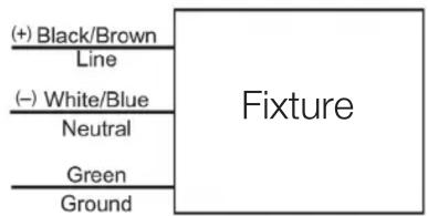
flowchart
graph TD
    A["+"] Black/Brown\nLine] --> B["Fixture"]
    C["-"] White/Blue\nNeutral] --> B
    D["Green"] --> B
    E["Ground"] --> B
INSTALLATION: Wall Mount (External Junction Box)
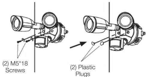
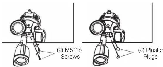
STEP 1: Disconnect power supply. Remove (2) plastic plugs. Remove inserted screws and mounting plate.
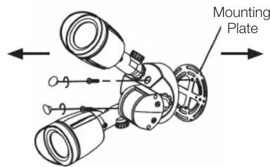
STEP 4: Connect the wires, refer to the Wiring Diagram.
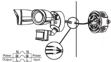
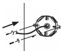
STEP 2: Attach junction box on the wall (not supplied).
STEP 5: Secure fixture onto mounting plate with screws, replace plastic plugs.
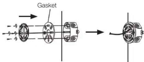
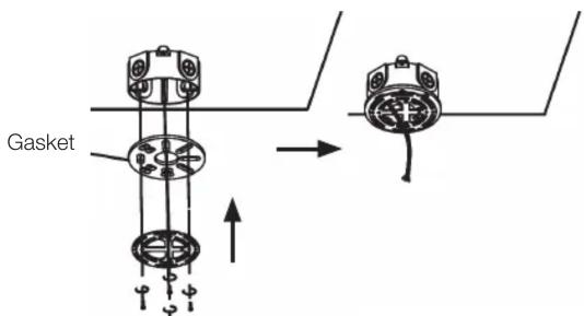
STEP 3: Fix mounting plate and gasket onto junction box.
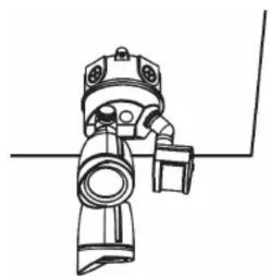
STEP 6: Check fixture and connect power supply.

natural_image
Technical line drawing of a mechanical assembly with no visible text or symbols
Satco Products, Inc.
Brent wood, NY 11717© Copyright 2020 S:
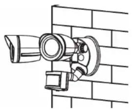
INSTALLATION: Wall Mount (Built-in Junction Box)
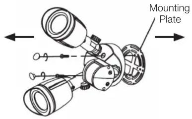
STEP 1: Disconnect power supply. Remove (2) plastic plugs. Remove inserted screws and mounting plate.
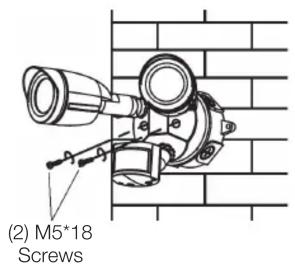
STEP 4: Secure fixture onto mounting plate with screws.
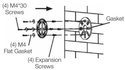
STEP 2: Drill (4) holes on the wall and insert expansion screws. Attach gasket and fix mounting plate with screws.
STEP 5: Replace plastic plugs.

STEP 3: Connect the wires, refer to the Wiring Diagram.
STEP 6: Check fixture and connect power supply.
natural_image
Technical line drawing of a mechanical assembly mounted on a brick wall (no text or symbols)INSTALLATION: Ceiling Mount
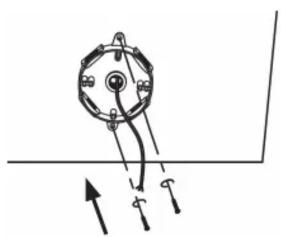
STEP 1: Disconnect power supply. Remove (2) plastic plugs. Remove inserted screws and mounting plate.
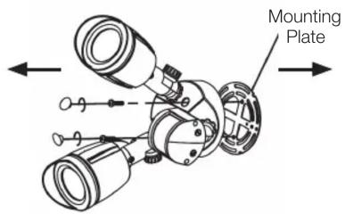
STEP 4: Connect the wires, refer to the Wiring Diagram.
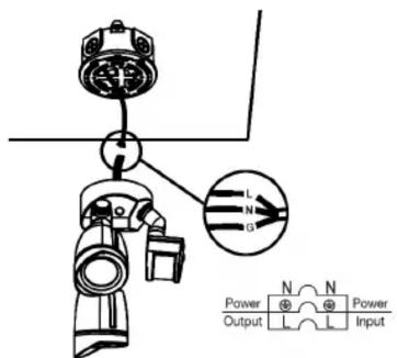
STEP 2: Attach junction box on the wall (not supplied).
natural_image
Simple line drawing of a mechanical component with arrows indicating motion (no text or symbols)STEP 5: Secure fixture onto mounting plate with screws, replace plastic plugs.
STEP 3: Fix mounting plate and gasket onto junction box.
STEP 6: Check fixture and connect power supply.
natural_image
Technical line drawing of a mechanical device with no visible text or symbolsTROUBLESHOOTING
- Check your power source.
-
Check electrical connections.
-
Check that the photocell or motion sensor is working properly (if so equipped).
ESPAÑOL:
Brand : NUVO
Model : 65/720
Category : Lighting