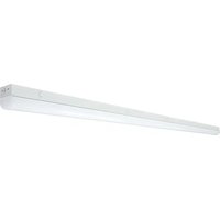
65/703 - Lighting NUVO - Free user manual and instructions
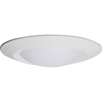
Find the device manual for free 65/703 NUVO in PDF.


| Brand | NUVO |
| Model | 65/703 |
| Product type | Indoor lighting fixture, surface mount |
| Color temperature | Selectable: 3500K, 4000K, 5000K |
| Power supply | 120-277 V AC, 50/60 Hz (estimate) |
| Power | Approximately 20W (estimate) |
| Dimensions | Approximately 300 mm x 300 mm (estimate) |
| Weight | Approximately 1.5 kg (estimate) |
| Protection rating | IP44 (suitable for damp locations) |
| Installation method | Surface mount on ceiling or wall |
| Housing material | Aluminum and polycarbonate (estimate) |
| Emergency option | Compatible with optional emergency power supply |
| Motion sensor option | Compatible with optional motion sensor |
| Safety | Installation by a qualified electrician; cut power before installation; grounding required |
| Maintenance | Clean with a soft dry cloth; do not use abrasive cleaners |
| Warranty | 2 years (common estimate) |
Frequently Asked Questions - 65/703 NUVO
User questions about 65/703 NUVO
0 question about this device. Answer the ones you know or ask your own.
Ask a new question about this device
Download the instructions for your Lighting in PDF format for free! Find your manual 65/703 - NUVO and take your electronic device back in hand. On this page are published all the documents necessary for the use of your device. 65/703 by NUVO.
USER MANUAL 65/703 NUVO
INSTALLATION AND SAFETY INSTRUCTIONS
IMPORTANT: Read before installing fixture. Retain for future reference.
WARNING: Risk of Fire or Electric Shock
- To reduce the risk of fire, electrical shock or injury to persons; read and follow all warnings and installation instructions before installing.
- All installation should be performed by a qualified electrician.
- To avoid electric shock, ensure power is turned off before installation.
- All wiring must be installed in accordance with all Electrical Codes.
- To prevent product malfunction and/or electrical shock, this product must be properly grounded.
- Suitable for damp locations.
- Suitable for non-insulated surface and frame. DO NOT cover fixture with insulation liner or similar material.
DO NOT install fixture on unstable or easily breakable surface.
DO NOT exert force on the surface of the fixture.
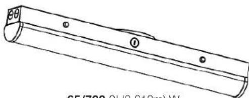
65/700 2' (0.610m) W
65/701 4' (1.2m) W
65/702 8' (2.4m) W
65/703 8' (2.4m) W
| Item # Description Finish/Details Volts Temperature CCT Watts | ||||||
| 65/700 2' | LINEAR STRIP WHITE FINISH 100-277V | WHITE | 100~277V | -20°C to 60°C | 3500K 4000K 5000K | 20W |
| 65/701 4' | LINEAR STRIP WHITE FINISH 100-277V | 30W 40W 50W | ||||
| 65/702 8' | LINEAR STRIP WHITE FINISH 100-277V | |||||
| 65/703 8' | LINEAR STRIP WHITE FINISH 120-347V 120~347V 82W | |||||
| 65/706 | 2' & 4' SUSPENSION KIT | 59" SUSPENSION LENGTH | - | - | - | - |
| 65/707 | 8' SUSPENSION KIT | 59" SUSPENSION LENGTH | - | - | - | - |
| 65/708 | ADD ON EM | 8W/1440LM/90 Min. Run Time | - | - | - | - |
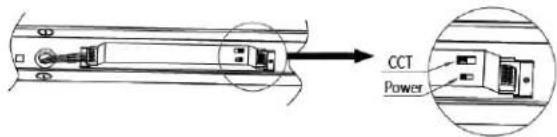
CCT INSTRUCTIONS
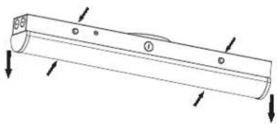
STEP 1: Press the Spring buttons and remove fixture cover.
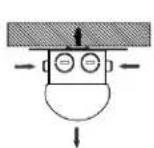
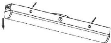
STEP 2: Position desired CCT to 3500K, 4000K or 5000K as needed. After selecting CCT, secure cover.
INSTALLATION - Surface Mount
STEP 1: Install appropriate anchors into the ceiling or wall.
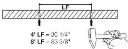
STEP 3: Secure fixture backplate on to the wall or ceiling using appropriate hardware.
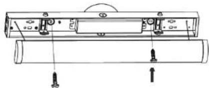
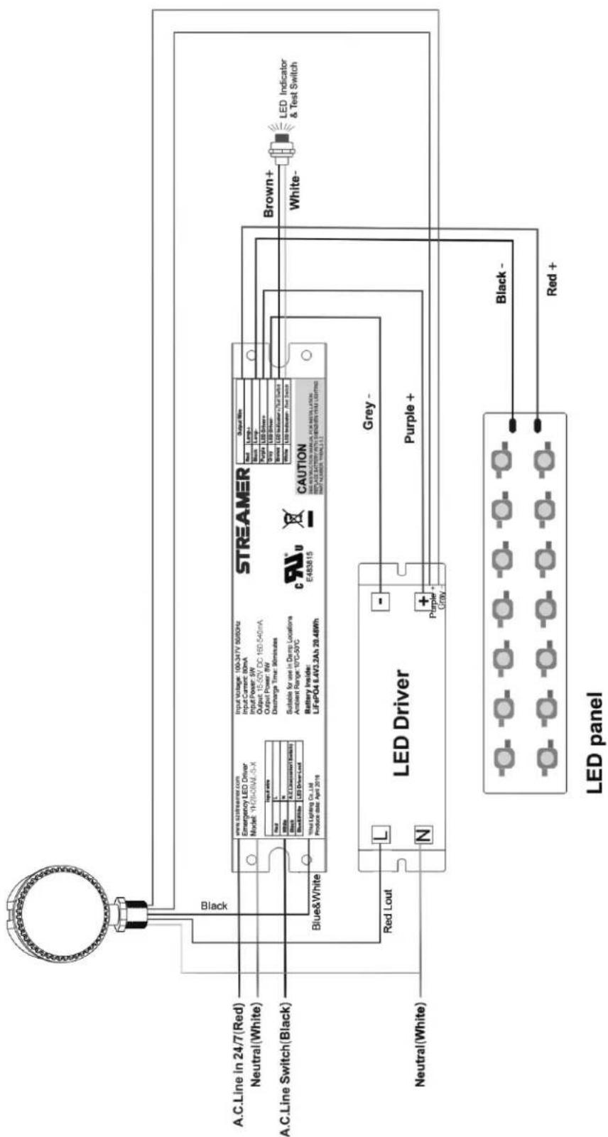
STEP 2: Turn OFF the power and connect wires by using wire nuts. See wiring diagram below.
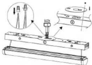
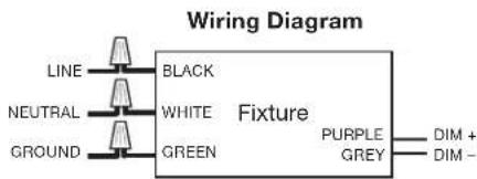
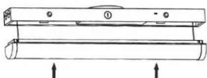
STEP 4: Press the cover upward and lock it with fixture springs. Installation of fixture is complete.

Salco Products, Inc. Brentwood, NY 11717
INSTALLATION - Optional EM Driver and Motion Sensor
STEP 1: Press the Spring buttons and remove fixture cover/diffuser.
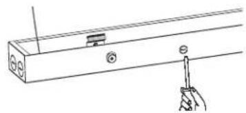
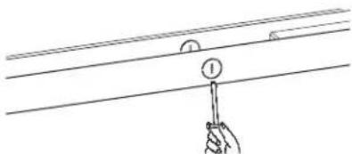
STEP 2: Use a flat screwdriver to remove knockouts on the bottom of fixture housing.
STEP 3: Align the Emergency power supply with the studs on the bottom housing and secure with supplied nuts.
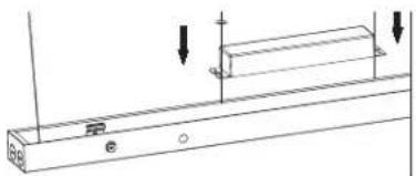
STEP 4: Image of the Emergency power supply installed.
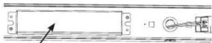
Optional Emergency power supply
STEP 5: Remove plastic nut from the Test/Indicator button.
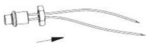
STEP 6: Install the Test/Indicator button through the knockout on the side of the fixture housing and secure with plastic nut.
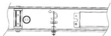
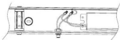
STEP 7: Connect wire leads from Test/Indicator button to wire leads from the Emergency power supply.
STEP 8: Remove the nut and washer of the Motion Sensor.
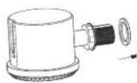
STEP 9: Use a flat screwdriver to remove knockout.
STEP 10: Install Motion Sensor stem by passing through the knockout on the side of the fixture housing.
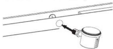
STEP 11: Install silicone washer and secure Motion Sensor stem with lock nut.
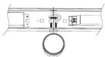
STEP 12: Image shows positioning of Motion Sensor.
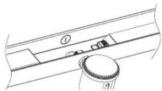
STEP 13: Connect the wires (see wiring diagram on page 3). Check wiring is correct, then put back the cover.
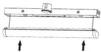
STEP 14: Image below shows positioning of the Test/Indicator button and Motion Sensor.
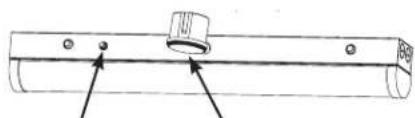
Test/Indicator button Motion Sensor
STEP 15: Installation of accessories is compete. Turn power on.
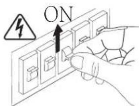
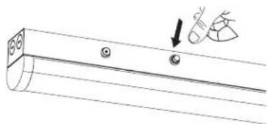
STEP 16: While main power is on: Start Emergency mode test by pressing the test button for .5 seconds (simulates the main power outage); Press test button again for 3 seconds to turn off the current Emergency mode.
Brand : NUVO
Model : 65/703
Category : Lighting