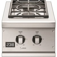
BGC132-BI-N - Barbecue Fisher & Paykel - Free user manual and instructions
Find the device manual for free BGC132-BI-N Fisher & Paykel in PDF.


| Product Type | Professional double built-in side burner |
| Brand | Fisher & Paykel (DCS) |
| Model | BGC132-BI-N |
| Installation Type | Built-in |
| Dimensions (W x D x H) | 57.79 cm x 56.20 cm x 26.99 cm |
| Estimated Weight | 20 kg |
| Materials | Stainless steel, cast iron, brass, porcelain |
| Number of Burners | 2 |
| Total Power | 34,000 BTUH (17,000 per burner) |
| Gas Supply | Natural gas or propane (convertible) |
| Working Pressure (natural gas) | 4.0 in WC |
| Working Pressure (propane) | 11 in WC |
| Ignition | Piezo with battery |
| Main Features | Powerful restaurant-style cooking, brass cap and crown burners |
| Cleaning and Maintenance | Removable porcelain grate, removable grease tray, dismountable burners |
| Safety | Gas shutoff, leak detection, lid, wait 5 minutes before relighting |
| Available Spare Parts | Caps, crowns, igniters, grates, grease trays |
| Repairability | User and installation manual, customer service |
| Usage | Outdoor only |
Frequently Asked Questions - BGC132-BI-N Fisher & Paykel
User questions about BGC132-BI-N Fisher & Paykel
0 question about this device. Answer the ones you know or ask your own.
Ask a new question about this device
Download the instructions for your Barbecue in PDF format for free! Find your manual BGC132-BI-N - Fisher & Paykel and take your electronic device back in hand. On this page are published all the documents necessary for the use of your device. BGC132-BI-N by Fisher & Paykel.
USER MANUAL BGC132-BI-N Fisher & Paykel
Professional side burner
BGC models
Installation instructions
and User guide
A MESSAGE TO OUR CUSTOMERS
We are glad that you selected the professional side burner by DCS. Because this appliance contains features not found on any other burner, we recommend that you read this entire booklet before your first use. Keep it in a handy place as it has answers to questions that may occur during future use.
Feel free to contact us if we can help you. When you write please include the model and serial number of the Burner. We thank you for buying the professional side burner and wish you many years of enjoyment.
To help serve you better, please fill out and submit your Product Registration by visiting our website at www.dcsappliances.com and selecting "Customer Care" on the home page and then select "Product Registration".
For your convenience, product questions can be answered by a DCS Customer Care Representative by phone: 1-888-936-7872, or email: customer.care@fisherpaykel.com.
NOTE: Please write the Model, Code and Serial Numbers on this page for references (located on the inside of the left side of the appliance)
MODEL NUMBER CODE SERIAL NUMBER
NOTE: Inspect the product to verify that there is no shipping damage. If any damage is detected, call the shipper and initiate a damage claim. DCS by Fisher & Paykel is not responsible for shipping damage.
DO NOT discard any packing material (box, pallet, straps) until the unit has been inspected.

WARNING!
Improper installation, adjustment, alteration, service or maintenance can cause property damage, injury or death. Read the installation, operating and maintenance instructions thoroughly before installing, using or servicing this equipment.

WARNING!
If the information in this manual is not followed exactly, a fire or explosion may result causing property damage, personal injury or death. Do not store or use gasoline or other flammable vapors and liquids in the vicinity of this or any other appliance. An LP cylinder not connected for use shall not be stored in the vicinity of this or any other appliance.

WARNING!
Do not try lighting this appliance without reading the "Lighting Instructions" section of this manual. This outdoor cooking gas appliance is not intended to be installed in or on recreational vehicles, boats or in a non-ventilated room. For outdoor use only.

FOR YOUR SAFETY
If You Smell Gas:
- Shut off gas to the appliance.
- Extinguish any open flames.
3.Openlid. - If odor continues, immediately call your gas supplier or your fire department
Installation and service must be performed by a qualified installer, service agency or the gas supplier.
PLEASE RETAIN THIS MANUAL FOR FUTURE REFERENCE.
TABLE OF CONTENTS
SAFETY PRACTICES AND PRECAUTIONS 4-5
INSTALLATION
Installation of Side Burner on 30" Cart 6-9
Installation of Side Burner Built-in Model 10-11
Gas Hook-up
12-13
Leak Testing
14
Burner Adjustment
14
Installer
15
Improper use or installation is dangerous. Carefully follow these instructions.
■ Always remove the cover before lighting the professional side burner. Never use the side burner if a leak is present.
■ Do not use a flame to check for gas leaks.
■ Do not let children use the side burner.
■ Do not leave children unattended near the side burner.
■ Never let children crawl or hang on the side burner.
Exercise care when operating the side burner. The burner grate can get hot enough to cause burns during operation.
■ Never leave the side burner on unattended.
■ Always wait 5 minutes before relighting the burner to allow any accumulated gas to dissipate. Should the burner go out during use, turn off the gas valve and wait 5 minutes before attempting to relight. Always follow the lighting instructions. Never lean over a lit burner.
■ Never cook without the drip pan in place, pushed all the way to the rear of the burner box.
■ Use only in well ventilated areas.
■ Do not use in garages, breezeways, sheds, or other such enclosed areas.
- Keep the area surrounding the side burner clear and free from combustible materials, gasoline, other flammable liquids or vapors, charcoal lighter fluid, and trash.
Do not obstruct the flow of combustion and ventilation air to the side burner. On cart mounted units, keep area beneath the burner free of debris. If the burner is built-in, do not store gas cylinders beneath the unit without adequate ventilation.

WARNING!
Do not store items of interest to children above or at the back of any appliance. Children could be seriously injured if they should climb onto the appliance to reach these items.
- Keep the side burner covered when not in use.
■ Never connect an unregulated gas line to the side burner.
If the side burner has not been used for an extended period of time (over winter, for example) the unit should be checked for gas leaks and obstructions in the burner.
■ Thoroughly clean the side burner on a regular basis.
■ Only use the side burner with the type of gas specified on the rating plate. To change from LP gas to natural, or vice versa, a factory conversion kit (see page 10 for conversion kit information) is required.
NOTE:
This product must be installed by a licensed plumber or gas fitter when installed within the Commonwealth of Massachusetts.
SAFETY PRACTICES & PRECAUTIONS

SPIDER AND INSECT WARNING!
Spiders and insects can nest in the burner(s) or orifices of this or any other gas appliance, and can block or restrict the burner. This can cause a flash back to the control panel. This is a very dangerous condition which can cause a fire to occur, thereby damaging the unit and making it unsafe to operate.
You must inspect the burner(s) at least once a year or immediately if any of the following conditions occur:
- The smell of gas in conjunction with the burner flames appearing yellow.
- The side burner(s) does not reach temperature.
- The side burner(s) heats unevenly.
- The burner(s) make popping noises.
■ Do not attempt to disconnect any gas connections while your burner is in use, or the gas supply is on.
■ When the side burner is stored indoors the gas supply must be disconnected and, if using an LP gas cylinder, the cylinder must be stored outdoors in a well-ventilated area.
- Keep any electrical supply cord away from the heated surfaces of the professional side burner.
On cart mounted units, never move without first allowing the side burner and/or grill to cool and ensuring that the gas supply is turned off. Fold the side shelf down, and push; never pull the grill.
■ Never use the side burner in a windy area.
INSTALLATION
INSTALLATION OF SIDE BURNER ONTO 30" CART (BGC 131/132 MODELS ONLY)
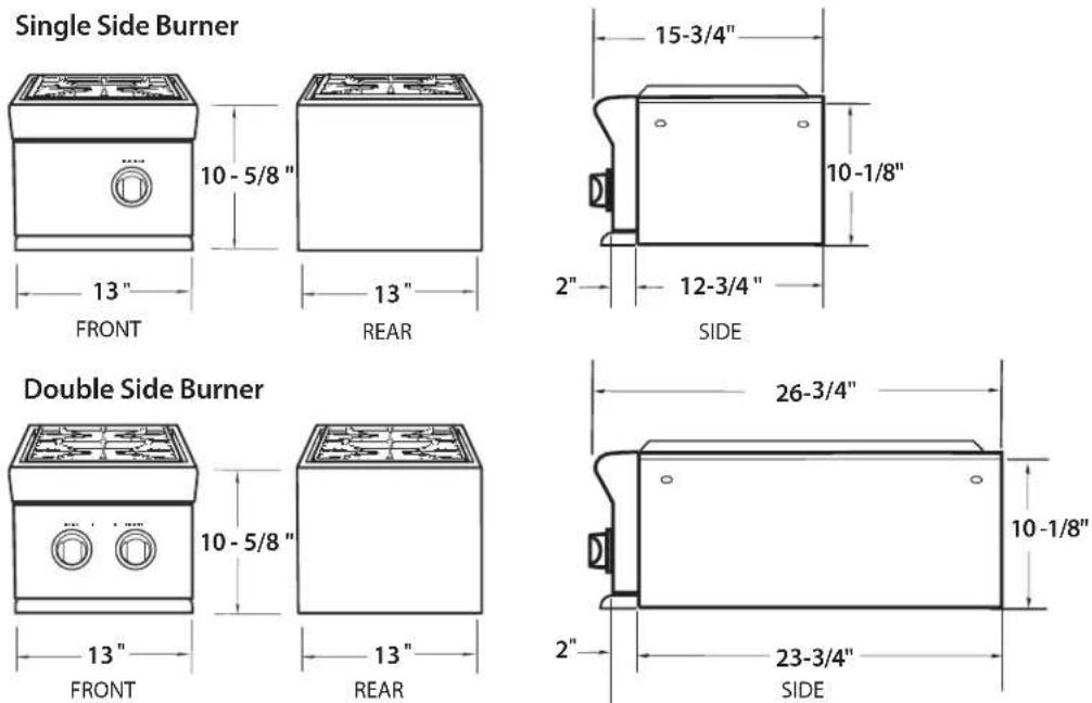
SIDE BURNER DIMENSIONS
INSTALLATION
INSTALLATION OF SIDE BURNER ON BGB30-CSS CART
STEP 1
Remove the cover, grate, and drip pan from the side burner.
STEP 2
Bolt the support brackets to the grill cart side panel with (4) 1/4 x 20 bolts provided.
Note:
For the BGC131 side burner only, use (2) #10 sheet metal screws to bolt the back support bracket.
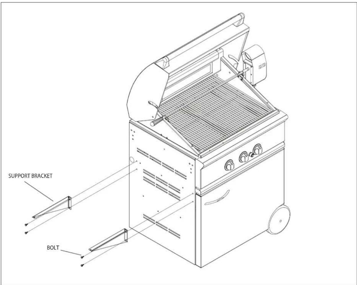
FIG. 01
INSTALLATION
INSTALLATION OF SIDE BURNER ON BGB30-CSS CART
STEP 3
- Bolt the side burner to the grill cart side panel from the under side of the burner assembly with a shoulder bolt in the front and 1/4 x 20 bolt in the back as shown. Do not forget to use 1/4 flat washers. Do not tighten. Adjust the side burner until it is level to the grill; then tighten securely.
- Bolt the support brackets to the bottom of the side burner with (4) #10-24 machine screws, nuts and washers provided.
- Replace the drip pan, grate and cover.
Note:
Once the side burner is assembled, refer to the "Gas Requirements" section for proper gas hook-up requirements.
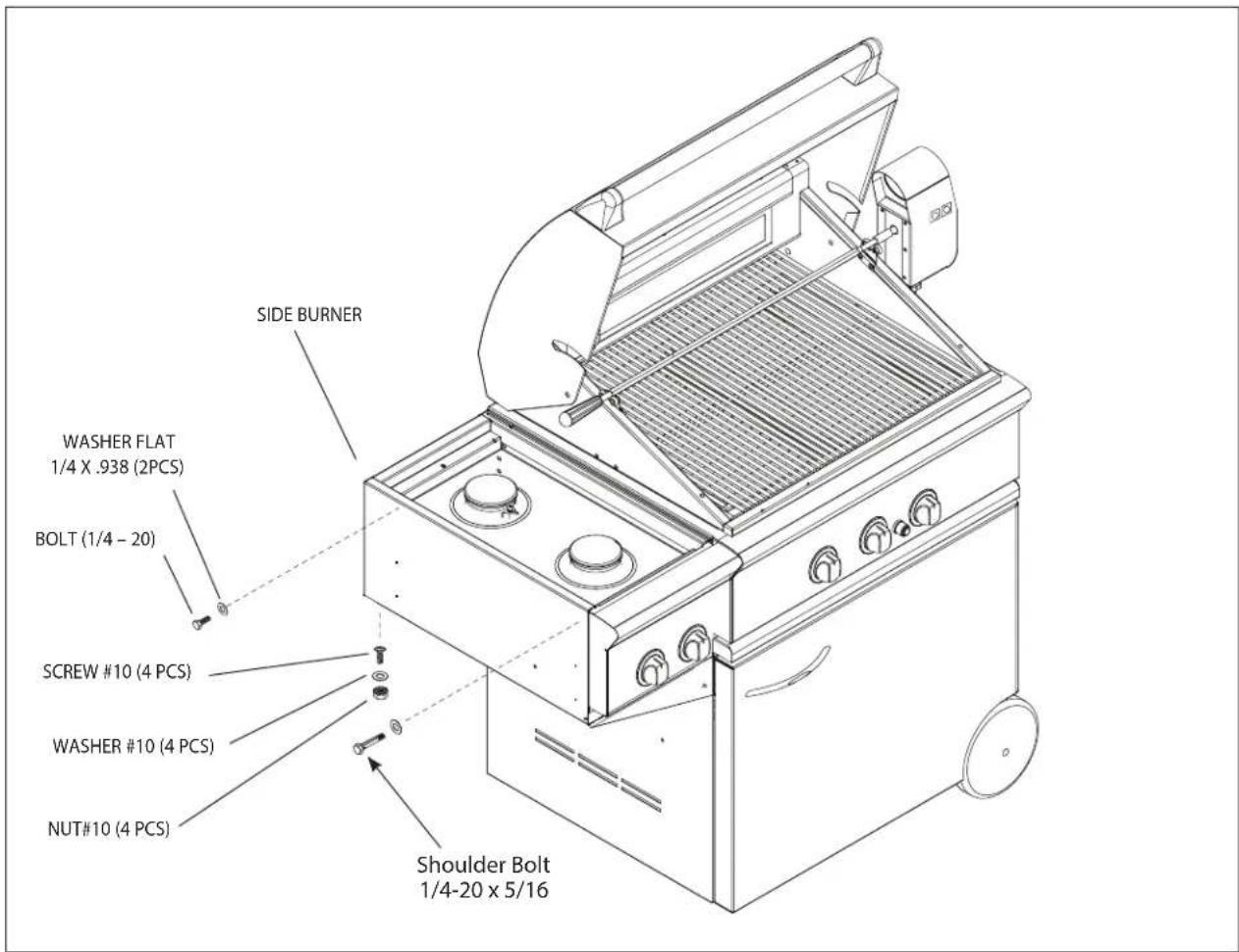
FIG. 02
INSTALLATION
INSTALLATION OF SIDE BURNER ON CAD1-30 CART
STEP 1
Remove the cover, grate, and drip pan from the side burner.
STEP 2
Attach the two provided 10-24 x 1 hex head bolts to the upper holes of the side panel. Do not completely tighten them yet. Leave an 1/8" space under the bolt head as shown on Fig. 03.
STEP 3
Use these two bolts to attach the side burner through the keyholes as shown on Fig. 03.

FIG. 03
INSTALLATION
INSTALLATION OF SIDE BURNER ON CAD1-30 CART
Apply vertical pressure to the side burner to align it with the grill cart. Attach the two provided 1/4-20 x 3/4 hex head bolts to the lower holes as shown in Fig. 04. Tighten the four bolts.

FIG. 04
NOTE:
Once the side burner is assembled, refer to the "Gas Requirements" section for proper gas hook-up requirements.
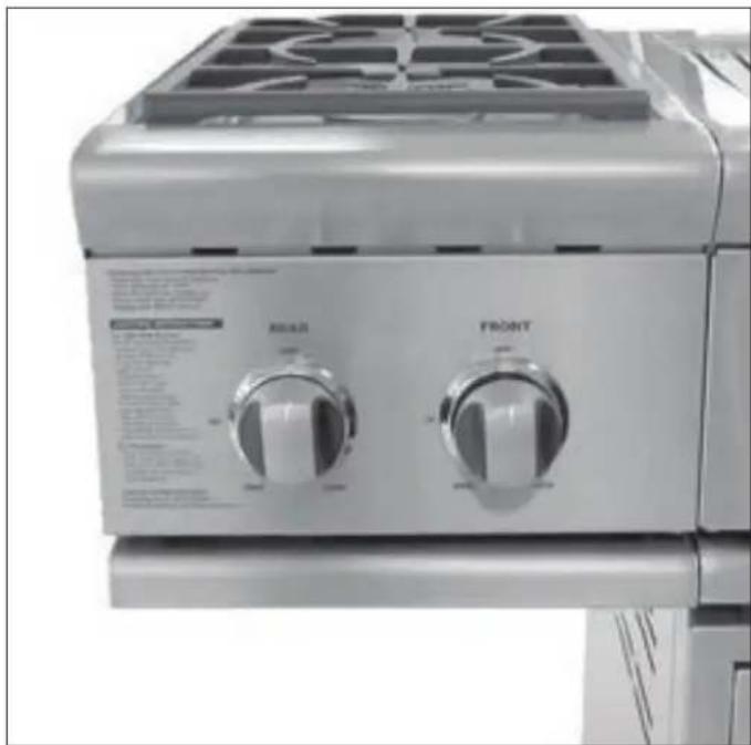
natural_image
Close-up of a kitchen appliance front panel with two rotary switches (no visible text or symbols)Assembled Side Burner to CAD1-30 Cart
INSTALLATION
INSTALLATION OF SIDE BURNER, BUILT-IN MODEL
All BGC131-BI and BGC132-BI models can be installed into a combustible enclosure with zero clearance from the back, side and bottom below the counter top level as shown in Fig. 05.
A minimum of 6" from the back and sides must be maintained from the professional side burner above the cooking surface (see Fig. 05).
When determining a suitable location, take into account concerns such as exposure to wind, proximity to traffic paths, and keeping any gas supply lines as short as possible. Locate the side burner only in a well-ventilated area. Never locate the side burner in a garage, breezeway, shed, or other such enclosed areas.
It is recommended that ventilation holes are provided in the enclosure in the event of a gas leak. The counter and supporting ledges or deck must be level and flat.
Important!
Gas fittings, regulator, and installer-supplied shut-off valves must be easily accessible.
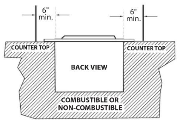
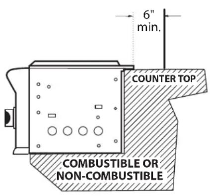
FIG.05
INSTALLATION
INSTALLATION OF SIDE BURNER, BUILT-IN MODEL
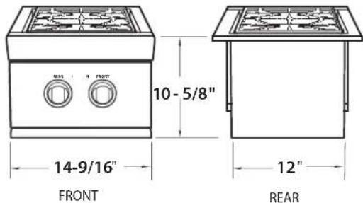
SIDE BURNER DIMENSIONS
Single Side Burner
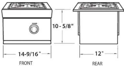
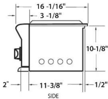
Double Side Burner
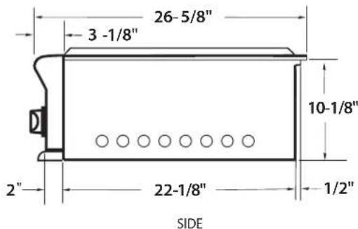
STANDARD CONSTRUCTION CUTOUT REQUIREMENTS
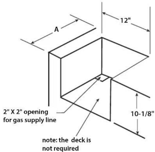
| MODEL A | |
| BGC131-BI | 12" |
| BGC132-BI 2 | 2-3/4" |
INSTALLATION
GAS HOOK-UP
GAS REQUIREMENTS:
Verify the type of gas supply to be used, either natural or LP. Make sure the marked gas on the appliance rating plate(s) and hook-up kit agrees with that of the supply.

IMPORTANT!
Never connect an unregulated gas line to the appliance.
An installer supplied gas shut-off valve must be installed in an easily accessible location.
All pipe sealants must be an approved type and resistant to the actions of LP gases. Never use pipe sealant on flare fittings.
Gas conversion kits are available from the factory. When ordering, have the model number, and the type of gas (natural or LP) which you need.
Total gas consumption of the professional side burner with burner(s) on "HIGH" – Table 1 below.
TABLE 1
| MODEL | Btu/hr |
| BGC131 | 17,000 |
| BGC132 | 34,000 |
| BGC131-BI | 17,000 |
| BGC132-BI | 34,000 |
The appliance and its individual shut-off valve must be disconnected from the gas supply piping system during any pressure testing of that system at test pressures in excess of 1/2 PSIG (3.5kPa.).
The appliance must be isolated from the gas supply piping system by closing its individual manual shut-off valve during any pressure testing of the gas supply piping system at test pressures equal to or less than 1/2 PSIG (3.5 kPa.).
The installation of this appliance must conform with local codes or in the absence of local codes, with the National Fuel Gas Code, ANSI Z223.1/NFPA 54. Installation in Canada must be in accordance with the Standard CSA B149 and/or .2 (installation code for gas burning appliances and equipment) and local codes.
All gas connections must be made by a qualified technician.
CONNECTION: 1/2" NPT male with 3/8" flare adapter.
OPERATING PRESSURE: 4.0" W.C.
SUPPLY PRESSURE: 5" to 14" W.C. If in excess of 14" W.C., a step down regulator is required.
Check with your local gas utility company or with local codes for instructions on installing gas supply lines. Be sure to check on type and size of run, and how deep to bury the line. If the gas line is too small, the professional side burner will not function properly.
INSTALLATION
GAS HOOK-UP
NATURAL GAS HOOK-UP (continued)
To hook-up the fittings supplied with the side burner, assemble as shown in Fig.06. Use joint compound on
male threads only.
Do not use joint compound on the flare end of the 1/2" NPT to 3/8" flare adapter. Ensure that the regulator arrow points in the direction of gas flow-towards the unit, away from the supply.
Do not forget to place the installer-supplied gas valve in an accessible location.
LP GAS HOOK-UP
CONNECTION: 1/2" NPT female with 3/8" flare adapter (included). Use 90° elbow 1/2" NPT with 3/8" flare (P/N 212394) for side mount models only when installing on the cart. Use sealer on 1/2" NPT threads only.
OPERATING PRESSURE: 11.0" W.C. side burner uses the LP regulator from adjoining grill.
SUPPLY PRESSURE: 12" to 14" W.C.
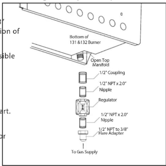
FIG. 06 Natural Gas
Apply joint compound to the threaded end of the side burner gas inlet and tighten the adapter to the pipe. Assemble the 24" and
30" hoses to the 3/8" flare tee, as shown in Fig.07. Tighten the regulator hose to the remaining fitting of the 3/8" flare tee.
LP TANK REQUIREMENTS
A dented or rusty LP gas cylinder may be hazardous and should be checked by your LP supplier. Never use a cylinder with a damaged valve.
■ The LP gas cylinder must be constructed and marked in accordance with the specifications for LP gas cylinders of the U.S. Department of Transportation (DOT) and designed for use with a Type 1 system only.
Do not change the regulator/hose assembly from that supplied with the unit or attempt to use a Type 1 equipped regulator/hose assembly with a standard 510 POL tank/valve assembly. The cylinder must be provided with a shut-off valve terminating in an LP gas supply cylinder valve outlet specified, as applicable, for connection Type 1.
If the appliance is stored indoors, the cylinder must be disconnected and removed from the appliance.
■ Cylinders must be stored outdoors in a well ventilated area out of the reach of children.
■ Gas cylinder supply must be turned off when not in use.
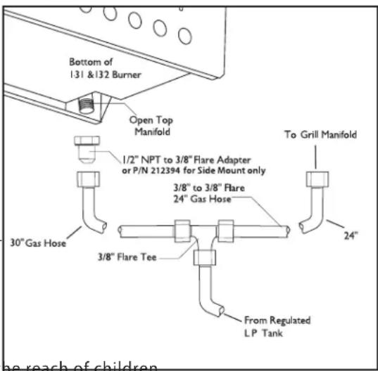
FIG. 07 LP Gas
INSTALLATION
LEAK TESTING

WARNING!
Do not smoke while leak testing. Extinguish all open flames.
Make a soap solution of one part liquid detergent, and one part water. Never test for leaks with an open flame. For LP units, check with a full cylinder. Make sure all control valves are in the "OFF" position. Turn the gas supply "ON". Check all connections from the supply line (Fig. 06), or LP cylinder(Fig. 07) up to the manifold pipe assembly (Fig. 08). Apply the soap solution around the connection with a spray bottle, brush, or rag. Soap bubbles will appear where leak is present. If a leak is present, turn off gas supply, tighten any leaking fittings, turn gas on, and recheck.

WARNING: IMPORTANT!
In! Act the gas supply piping or hose prior to turning the gas "ON". If there is evidence of cuts, wear or abrasion, it must be replaced prior to use. Do not use the side burner if the odor of gas is present. Turn the control knob to "OFF", then turn off the gas supply. If using LP, is there gas in the tank?
Always keep your face and body as far away from the burner as possible when lighting.
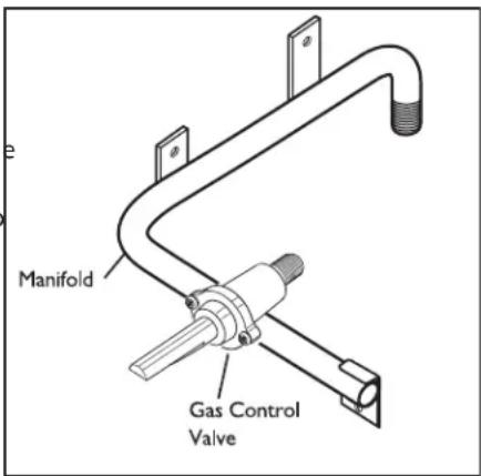
FIG. 08
BURNER ADJUSTMENT
BURNERS
Your new side burner is equipped with burners typical of those used in restaurants (Fig. 09). These burners are designed for maximum cleanability and controlability. The burner should never be operated if the cap is not in place.
BURNER EFFICIENCY AND FLAME CHARACTERISTICS
It is necessary to keep the burner ports and the igniters clean for proper light performance of the burners. The burner flame should burn complete-around the burner with no excessive noise or lifting. The flame should be blue color and stable with no yellow tips. During initial use, foreign par-cles in the gas line, or dust in the air around the appliance may cause orange flame. This will disappear with use.
FLAME HEIGHT
The correct height of the flame mainly depends on the size of the bottom of the cooking utensil, the material of the cooking utensil, the amount and type of food and the amount of liquid in the utensil. The following are some basic rules for selecting flame height.
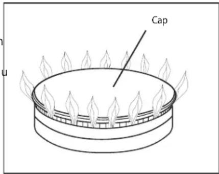
FIG. 09
■ For safety reasons the flame must never extend beyond the bottom of the cooking utensil. Never allow flames to curl up the side of the pan (see Fig.10).
■ Utensils which conduct heat slowly (such as glass-ceramic) should be used with medium to low flames. If you are cooking with a large amount of liquid, a slightly larger flame can be used.
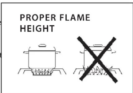
FIG. 10
INSTALLATION INSTALLER CHECKLIST
■ Specified clearances maintained to combustibles.
■ Side burner is properly mounted.
■ All internal packaging removed.
■ Burner is seated properly and does not rock.
■ Each burner lights satisfactorily, individually or with adjacent burner lit.
■ Knob(s) turn freely. Bezel(s) centered.
■ Flame adjusted.
■ Pressure regulator connected and set for 4.0"W.C. Natural, 11"W.C. LP gas.
■ Manual shut-off valve installed and accessible.
■ Unit tested and free of leaks.
■ User informed of gas supply shut-off valve location.
■ Battery installed in module properly and generates ignition spark when activated.
PLEASE LEAVE THESE INSTRUCTIONS WITH THE USER.
USER, PLEASE RETAIN THESE INSTRUCTIONS FOR FUTURE REFERENCE.
First remove the burner cover and any cooking utensils from the burner grate. Push and turn the control knob to the "HI" position until the burner is lit or 4 seconds pass. If the burner doesn't ignite, wait 5 minutes for any accumulated gas to dissipate then try again. If the burner will not light after several attempts, check the trouble-shooting instructions on page 18.
MATCH LIGHTING
Hold a lit fireplace match near the burner ports, turn the control knob counterclockwise to "HI". Rotate the knob immediately once the burner is lit to the desired setting.
Note:
If you are using propane gas, a slight pop or flash may occur at the burner ports a few seconds after the burner has been turned "off". This "extinction pop" is normal for propane gas.
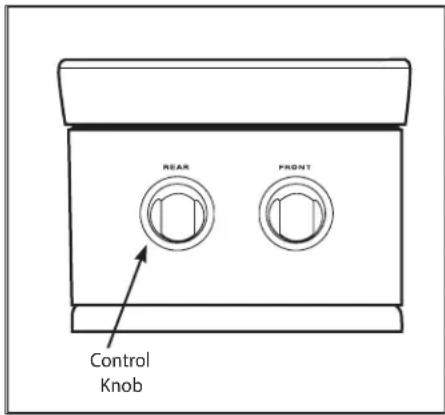
FIG. 11 BGC132 Shown
CARE AND MAINTENANCE
The side burner will give you years of trouble free service if properly maintained. The body panels and front valve panel and burner hanger are made from non-rusting high grade stainless steel. The burner is heavy duty cast iron and brass. The venturi tube is brass.
STAINLESS STEEL
There are many different stainless steel cleaners available. Always use the mildest cleaning procedure first, scrubbing in the direction of the grain. Do not use steel wool as it will scratch the surface. To touch up noticeable scratches in the stainless steel, sand very lightly with wet 100 grit emery paper in the direction of the grain.
SIDE BURNER GRATE
The side burner grate is porcelain enamel over cast iron for durability. To avoid burns, do not clean a hot grate. They may be wiped while in place with hot, soapy water, rinsed and wiped dry thoroughly. Never immerse a hot grate in water. Due to rapid temperature changes the porcelain may pop off the edges of the grates. If the grates develop chips, do not be concerned as the base metal, cast iron, soon darkens to blend with the porcelain enamel. Use care when wiping areas where the enamel has popped off, the edges may be sharp. If cleaning necessitates grate removal, care should be taken in lifting them. They are very heavy. Be sure to place them on a protected surface.
DRIP TRAY
A stainless steel drip tray with a stainless steel handle is lo under the burner.
It collects any boil-overs or spills. Pull forward to remove washed off as soon as possible to prevent baked on soil.
BURNERS
For proper lighting and performance, keep the burners cl necessary to clean the burners if they do not light even th the igniter clicks, if there has been a severe boil over, or when the flame does not burn blue. Be certain all burner knobs are in the off position before attempting to clean t The burners have been designed for ease of cleaning. Wh the grate and burners are cool, remove the grate. The burner cap and the brass port ring can easily be lifted off. Wash these parts in hot soapy water, rinse and dry thorou burner caps are porcelain enamel, follow the directions th given for the burner grates. A bristle brush can be used t toothed burner ports, if necessary. After cleaning, it is im make sure the location pins on the bottom side of the por properly aligned with the corresponding holes in the base rect alignment will produce a potentially dangerous flame and poor burner performance (see Fig. 12).
ELECTRODES
Wipe with a water dampened cotton swab. Be careful not to damage the electrode (see Fig. 13)
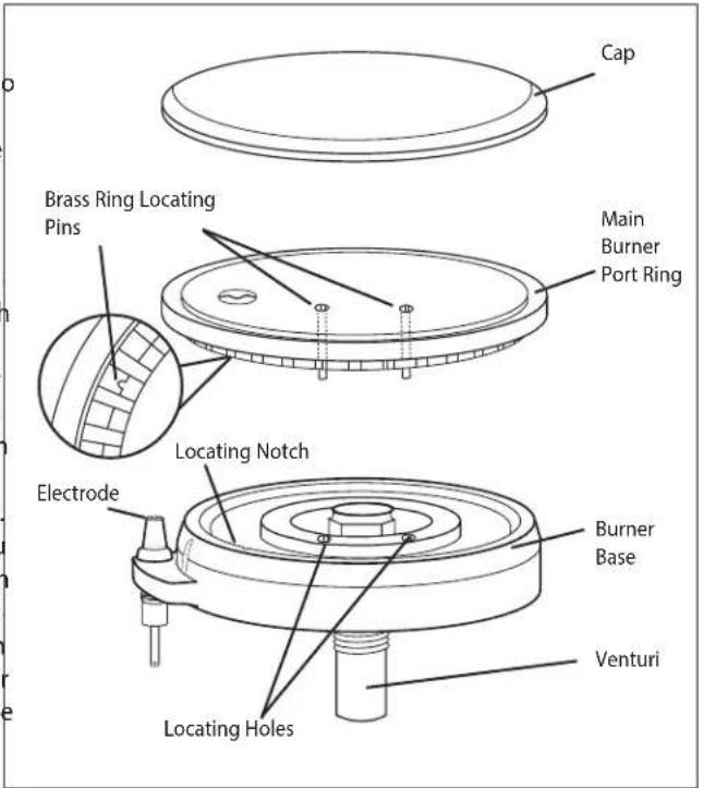
FIG. 12
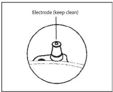
FIG. 13
TROUBLESHOOTING
PROBLEM
WHAT
TO
DO
| Burner won't light when the ignition is pushed. | Remove the burner grate. With the control knob in the "OFF" position, push the control knob in and listen to the electrode. There should be a spark from the electrode. When the spark jumps, it makes a ticking sound.If there is no spark......Could be a dead battery. Try replacing the battery.Or the air gap between an electrode tip and a contact metal is too far (gap should be 1/8") or dirty.If there is a spark... is there gas supplied to the unit and is the line purged of air? See Fig. 06 and Fig. 07.Does the other burner of a dual burner model operate?Check the orifice or venturi for blockage. |
| Burner flame is yellow or orange, in conjunction with the odor of gas. | Check the burner for obstructions or dirt. See page 14.Check for proper gas supply or wrong gas type.Is the side burner in a dusty area? Move to less dusty area if possible. |
| Low heat with knob in "HI" position. | Is the fuel hose bent or kinked? See Fig. 06 and Fig. 07.Is there adequate gas supply available? If it is only one burner of the dual burner unit that appears low, does the burner need cleaning? See Fig. 12 and Fig. 13.If using LP gas, check for empty tank or low fill level. |
SERVICE
HOW TO OBTAIN SERVICE:
For warranty service, please contact your local service provider or DCS Customer Care at (888) 936-7872. Before you call, please have the following information ready:
■ Model Number (located on the inside of the left side of the appliance)
■ Serial Number (located on the inside of the left side of the appliance)
■ Code (located on the inside of the left side of the appliance)
Gas Type
■ Date of installation
■ A brief description of the problem
Your satisfaction is of the utmost importance to us. If a problem cannot be resolved to your satisfaction, please write or email us at:
Write:
Fisher & Paykel Appliances Inc.
Attention: DCS Customer Care
695 Town Center Drive, Suite 180
Costa Mesa, CA 92626-1902 USA
email: customer.care@fisherpaykel.com
BEFORE YOU CALL FOR SERVICE:
- Check troubleshooting on page 18.
- Is the gas turned on?
- Is there a dead battery in the ignition module?
À L'INTENTION DE NOS CLIENTS
FIG. 01
INSTALLATION
BRÛLEUR LATÉRAL BGC131/132 À CHARIOT - MODÈLES BGB30-CSS
ÉTAPE 3
natural_image
Close-up of a kitchen appliance front panel with two rotary switches (no visible text or symbols)Fisher & Paykel Appliances Inc.
Attention: DCS Customer Care
695 Town Center Drive, Suite 180
Costa Mesa, CA 92626-1902 USA
email: customer.care@fisherpaykel.com
Copyright © Fisher & Paykel 2014. All rights reserved.
The product specifications in this booklet apply to the specific products and models described at the date of issue. Under our policy of continuous product improvement, these specifications may change at any time. You should therefore check with your Dealer to ensure this booklet correctly describes the product currently available.

- A MESSAGE TO OUR CUSTOMERS
- WARNING!
- FOR YOUR SAFETY
- TABLE OF CONTENTS
- NOTE:
- SAFETY PRACTICES & PRECAUTIONS
- SPIDER AND INSECT WARNING!
- INSTALLATION
- INSTALLATION OF SIDE BURNER ONTO 30" CART (BGC 131/132 MODELS ONLY)
- INSTALLATION OF SIDE BURNER ON BGB30-CSS CART
- STEP 1
- STEP 2
- STEP 3
- INSTALLATION OF SIDE BURNER ON CAD1-30 CART
- INSTALLATION OF SIDE BURNER, BUILT-IN MODEL
- Important!
- SIDE BURNER DIMENSIONS
- STANDARD CONSTRUCTION CUTOUT REQUIREMENTS
- GAS HOOK-UP
- GAS REQUIREMENTS:
- NATURAL GAS HOOK-UP (continued)
- LP GAS HOOK-UP
- LP TANK REQUIREMENTS
- LEAK TESTING
- WARNING: IMPORTANT!
- BURNER ADJUSTMENT
- BURNERS
- BURNER EFFICIENCY AND FLAME CHARACTERISTICS
- FLAME HEIGHT
- INSTALLATION INSTALLER CHECKLIST
- MATCH LIGHTING
- CARE AND MAINTENANCE
- STAINLESS STEEL
- SIDE BURNER GRATE
- DRIP TRAY
- ELECTRODES
- TROUBLESHOOTING
- SERVICE
- HOW TO OBTAIN SERVICE:
- BEFORE YOU CALL FOR SERVICE:
- À L'INTENTION DE NOS CLIENTS
- BRÛLEUR LATÉRAL BGC131/132 À CHARIOT - MODÈLES BGB30-CSS
- ÉTAPE 3
Brand : Fisher & Paykel
Model : BGC132-BI-N
Category : Barbecue