
225-2-27 - Garage door spring Vevor - Free user manual and instructions
Find the device manual for free 225-2-27 Vevor in PDF.
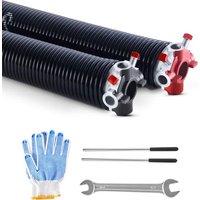


| Product Type | Torsion Spring for Garage Door |
| Brand | Vevor |
| Model | 225-2-27 |
| Wire Diameter | 0.225 inches (5.7 mm) |
| Inner Diameter | 2 inches (50.8 mm) |
| Length | 27 inches (685.8 mm) |
| Material | 82B Die-Cast Steel |
| Winding Direction | Right-hand (R) and Left-hand (L) - one of each supplied |
| Number of Springs | 2 |
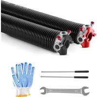
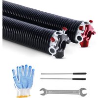
| Components Included | 2 springs, 2 winding bars, 1 pair of gloves, 1 mounting wrench, 1 manual |
| Usage | Counterbalance a sectional door |
| Safety | High tension: professional handling recommended; release tension before servicing |
| Installation | Professional installation strongly advised; requires tools and experience |
| Maintenance | Clean with a mild cleaner and a soft brush several times a year; lubricate with light oil spray once a year |
| Warranty | Electronic warranty certificate available at www.vevor.com/support |
| Repairability | Spare parts available (springs, bars, gloves, wrench) |
| General Information | Brand Vevor, motto "Tough Tools, Half Price"; imported by Sanven Technology Ltd. (USA) and others |
Frequently Asked Questions - 225-2-27 Vevor
User questions about 225-2-27 Vevor
0 question about this device. Answer the ones you know or ask your own.
Ask a new question about this device
Download the instructions for your Garage door spring in PDF format for free! Find your manual 225-2-27 - Vevor and take your electronic device back in hand. On this page are published all the documents necessary for the use of your device. 225-2-27 by Vevor.
USER MANUAL 225-2-27 Vevor
Technical Support and E-Warranty Certificate www.vevor.com/support
GARAGE DOOR SPRING
MODEL: 207-2-24/250-2-35/225-2-27/250-2-31/234-2-28/234-2-31/250-2-32/218-2-26/225-2-24 GZ-22/GZ-23/GZ-24/GZ-28/GZ-29/GZ-30
We continue to be committed to providing you with tools at competitive prices.
"Save Half", "Half Price" or any other similar expressions used by us only represent an estimate of savings you might benefit from buying certain tools with us compared to the top brands and do not necessarily mean to cover all categories of tools offered by us. Kindly be reminded to verify carefully when placing an order with us if you are saving half in comparison with the top major brands.
MODEL: 207-2-24/250-2-35/225-2-27/250-2-31/234-2-28/
234-2-31/250-2-32/218-2-26/225-2-24/GZ-22/GZ-23/GZ-24/GZ-28/GZ-29/
GZ-30
NEED HELP? CONTACT US!
Have product questions? Need technical support? Please feel free to contact Technical Support and E-Warranty Certificate at www.vevor.com/support
This is the original instruction. Please read all manual instructions carefully before operating. VEVOR reserves a clear interpretation of our user manual. The appearance of the product shall be subject to the product you received. Please forgive us that we won't inform you again if there are any technology or software updates on our product.
SAFETY INSTRUCTIONS
WARNING
- Properly handle and install torsion springs, expansion springs, and other garage door hardware, otherwise, serious injury or death may occur!
- Read and understand all the instructions before you start working.
- Professional installation is recommended.
- Do not attempt to install yourself unless you have the right tools, reasonable mechanical ability, experience, and upper arm strength.
- Springs and accessories are under extreme tension at all times. Tension must be released from springs before any work is performed.
- Pay attention to the safety of surrounding personnel during installation.
MODEL AND PARAMETERS
| Model\Description | Wire Diameter x Inside Diameter x Le | Material |
| 207-2-24 | 0.207x2x24inch | 82B & CastAluminum |
| 250-2-35 | 0.250x2x35inch | |
| 225-2-27 | 0.225x2x27inch | |
| 250-2-31 | 0.25x2x31inch | |
| 234-2-28 | 0.234x2x28inch | |
| 234-2-31 | 0.234x2x31inch | |
| 250-2-32 | 0.25x2x32inch | |
| 218-2-26 | 0.218x2x26inch | |
| 225-2-24 | 0.225x2x24inch | |
| GZ-22 | 0.207x2x22inch | 82B & Cast Aluminum |
| GZ-23 | 0.218x2x23inch | |
| GZ-24 | 0.218x2x24inch | |
| GZ-28 | 0.25x2x28inch | |
| GZ-29 | 0.25x2x29inch | |
| GZ-30 | 0.25x2x30inch |
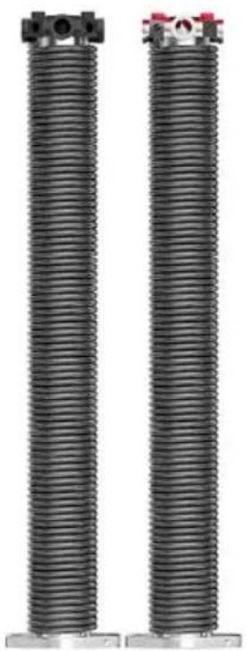
STRUCTURE DIAGRAM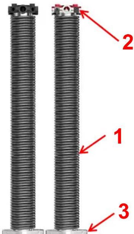
- Torsion Spring 2. Regulating Block 3. Fixed Block
COMPONENTS
| No. | Pictu re | Name | Qty |
| 1 |  | Spring(Dextrorotary) | 1 |
| 2 |  | Spring(Levorotary) | 1 |
| 3 |  | Winding Bars | 2 |
| 4 |  | Gloves | 1 Pair |
| 5 | 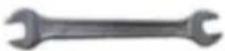 | Mounting Wrench | 1 |
| 6 |  | User Manual | 1 |
PRODUCT USAGE
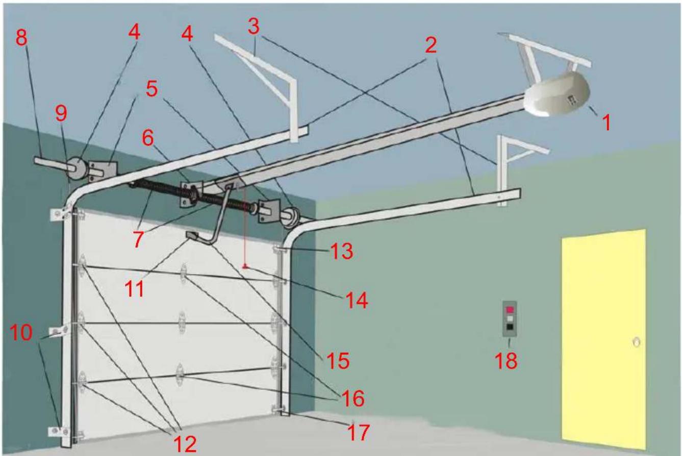
- Door Machine 2. Horizontal Guide Rail 3. Horizontal Guide Rail Bracket
- The Wire Wheel 5. Edge Shaft Shelf 6. Axis Shelf 7. Torsion Spring 8. Torsion Spring Shaft 9. Wire Rope 10. Vertical Guide Rail Bracket
- Door Stents 12. On both sides of the Hinge and Roller 13. Top Bracket and Roller 14. Emergency Release Shake Handshandle
- Connecting Rod 16. Center Hinge 17. Bottom Bracket and Roller
- Wall Button Switches
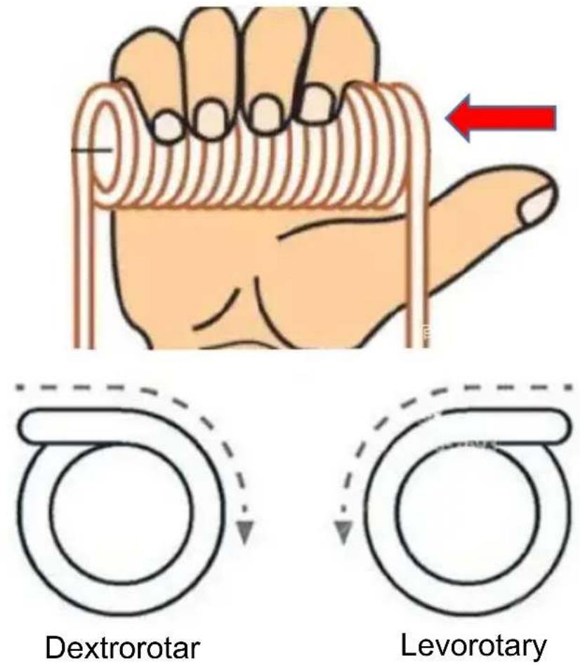
Levorotary/Dextrorotary Distinction:

L (Levorotary) / R (Dextrorotary)
HELPFUL TRICK: Make an "O" with your index finger and thumb. Using the tip of your finger as the end of the wire, follow the direction down your finger and it will give you the direction the spring is coiled.
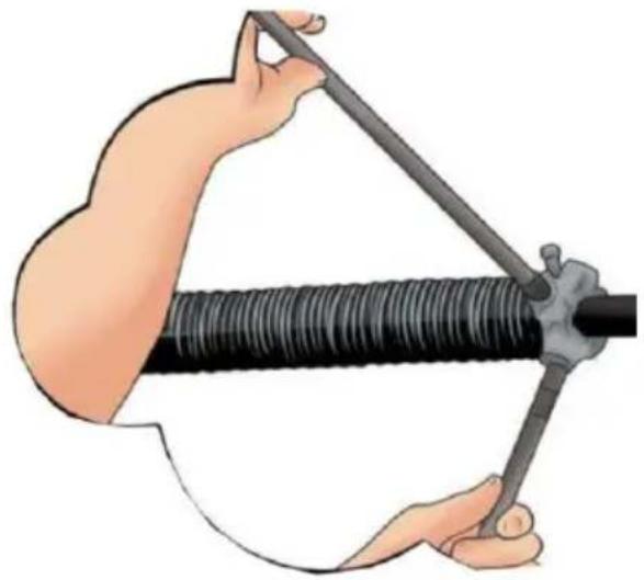
Adjust the Spring Tension: It is dangerous to adjust the torsion spring; please call a professional to adjust.
REMOVING THE OLD SPRINGS
WARNING
It is dangerous to remove the torsion spring. Please call a professional to operate.
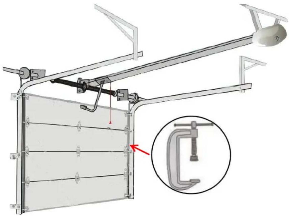
- Unplug the garage door opener and clamp the door to the track. Disconnect the garage door opener so the door remains closed. Use locking pliers or a C-clamp to secure the door to the track to keep it from opening when you release the tension on the springs.
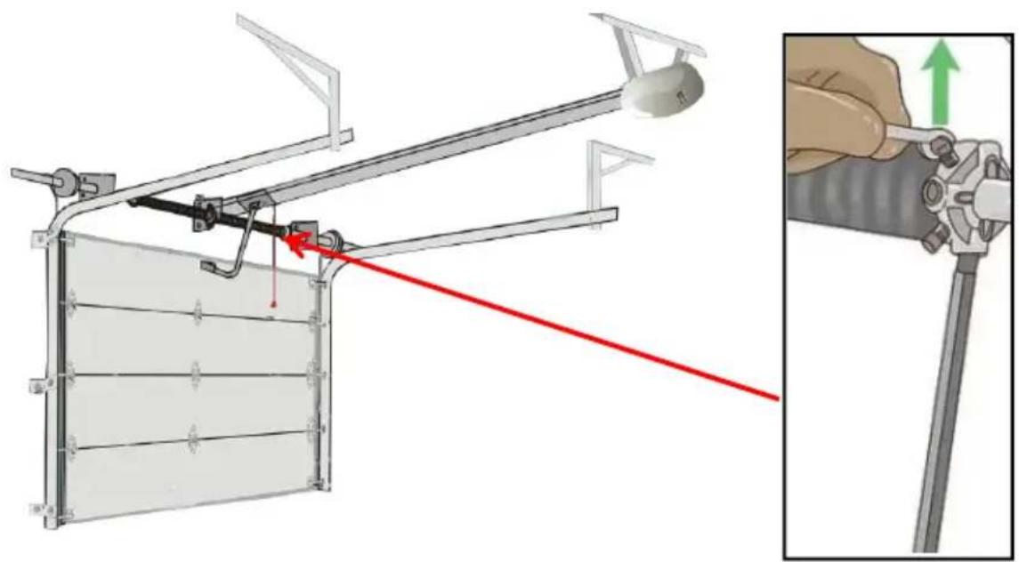
- Loosen the set screws while holding each spring with a winding bar. Position a sturdy ladder to the side of the springs, rather than working directly in front of them, for safety reasons. Put on eye protection and leather gloves. Push a winding bar into the bottom hole of the winding cone on the outside of 1 spring. Use a wrench to loosen the 2 set screws. Keep a firm grip on the bar as the spring will expand powerfully as screws are released. Repeat on the other side. To ensure the bars fit securely into the winding cone holes, file down the ends.
Note:
A: Using a screwdriver, pin punch, or plier handles to unwind the bar could result in serious injury, as these tools aren't designed to hold the spring in place.
B: Avoid standing on a bucket or chair to reach the springs. Use a ladder to minimize the risk of injury.

- Unwind each spring with the help of 2 winding bars.
Position the second winding bar into a hole on the winding cone at a perpendicular angle to the first. Unwind the spring 1/4 turn at a time, moving the 1 winding bar to the next open perpendicular position after each 1/4 turn. Repeat on the other spring.
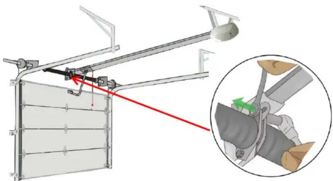
- Remove the nuts and bolts, then slide the springs to the end brackets. Using a wrench, remove the 2 nuts and bolts that secure each spring to the center bracket. Then slide each spring toward the end bracket.
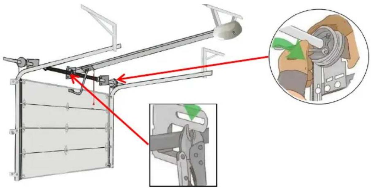
- Secure the tube and remove the springs, cables, and cable drums. Use locking pliers or a C-clamp to secure the torsion tube to the center bracket to keep it from moving. Then, use a wrench to loosen the set screws on both lift cable drums. Disconnect the lift cables, then slide the cable drums and springs off the torsion tube.
Note: Securing the tube is an essential step that will prevent the tube from moving around and potentially injuring you, so be sure to fully lock it in place.
WARNING
It is dangerous to install the torsion spring. Please call a professional to operate.
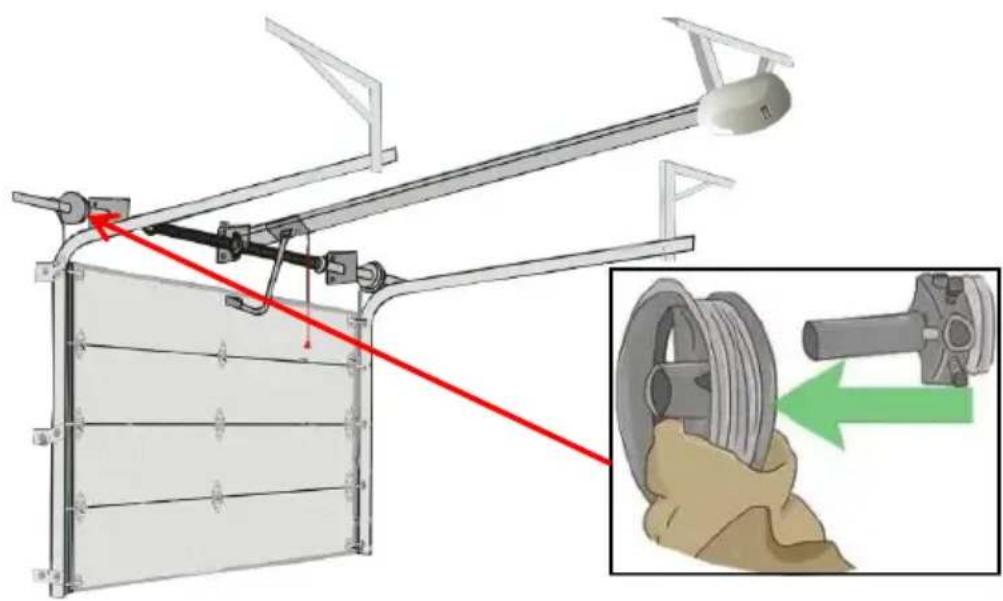
- Slide the left spring onto the tube and add the cable drum.
When your new springs arrive, put the new left spring on the torsion tube, making sure that the stationary cone on the end of the spring faces the center bracket. After sliding the new spring into place, replace the cable drum and insert the torsion bar into the left bearing bracket.
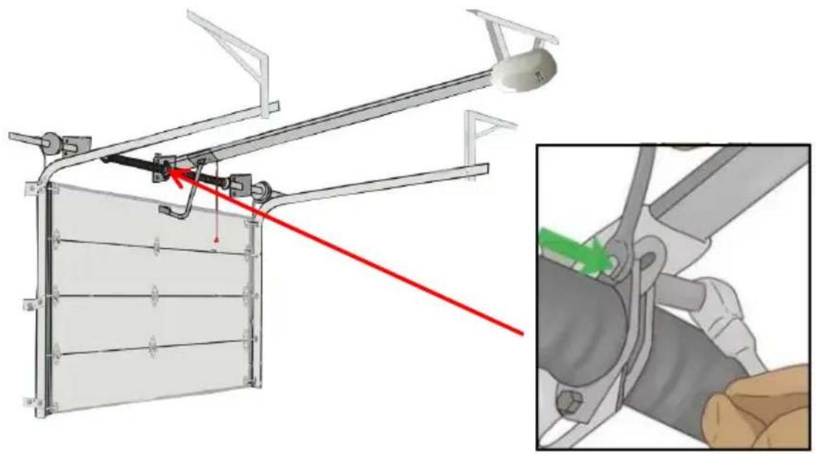
- Install the center bearing and the right spring, then secure the cones. Slide the torsion bar to the left, then add the center bearing. Slide the right spring onto the bar and press the bearing into the stationary cone. Connect both of the stationary cones to the center bracket with the nuts and bolts you removed previously. Remove the locking pliers or clamp from the center bracket.
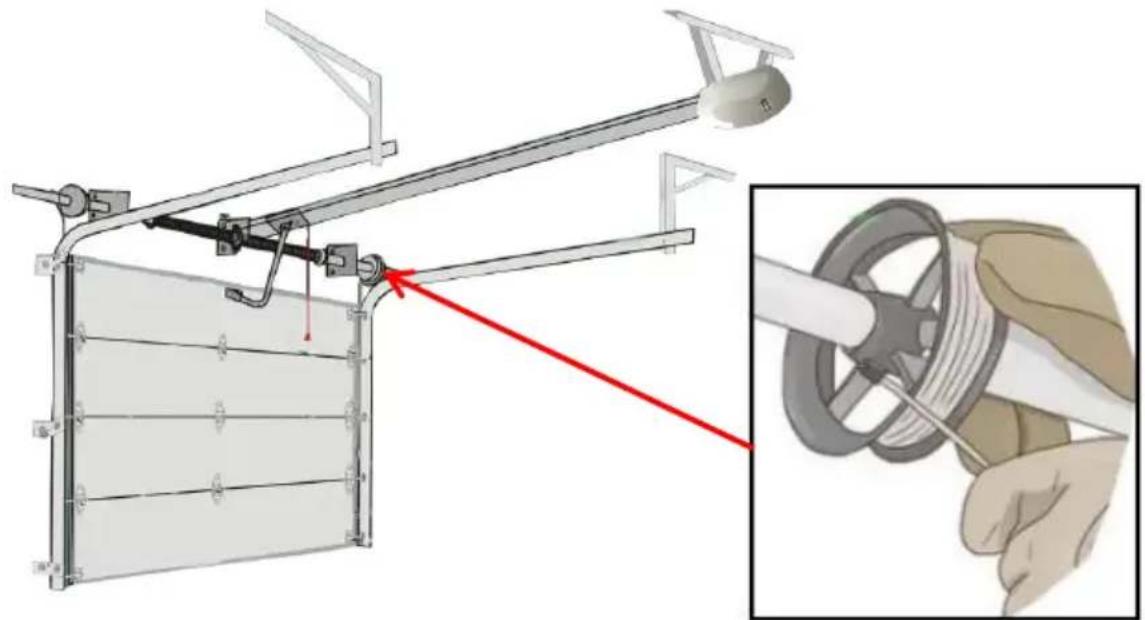
- Thread the cables and tighten the drums.
Run the lift cable between the roller and the doorjamb. Slip the lift cable end through the cable slot on the drum. Then attach locking pliers to the torsion tube to secure it in place. Spin the drum to wind the cable into the grooves, then tighten the set screws. Repeat on the other side, leaving the locking pliers in place.
Note: For the door to operate properly, you need the same amount of tension on both sides, so take care to tighten each side evenly.
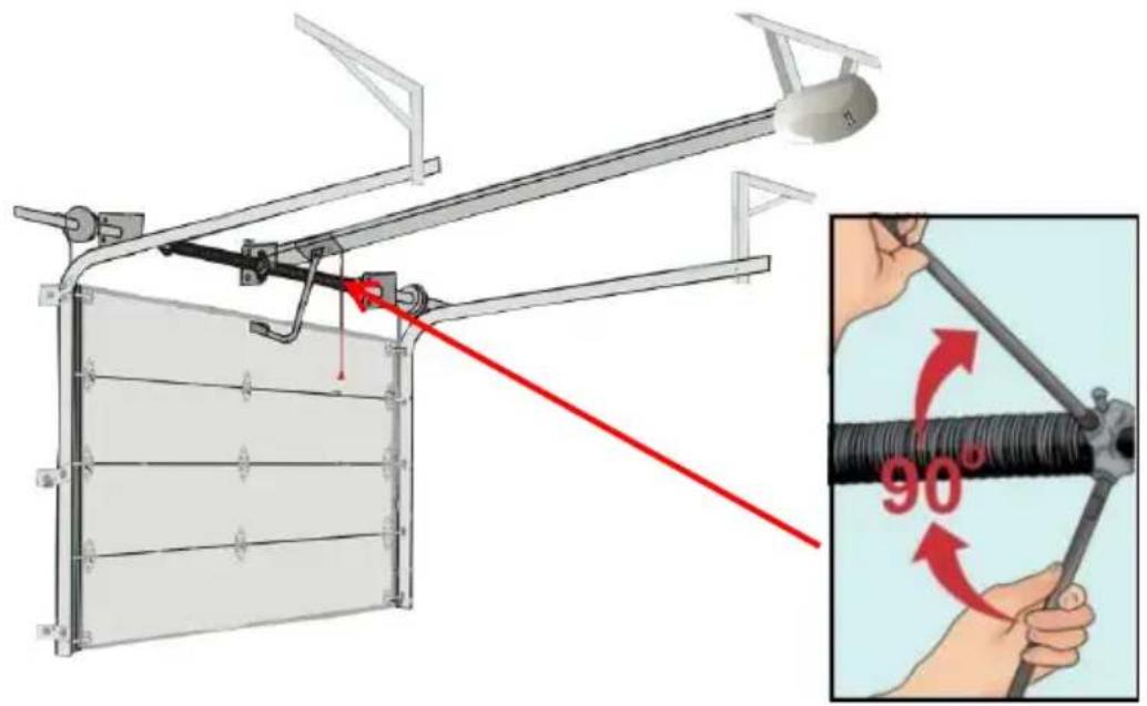
- Wind the springs.
Insert 2 winding bars into the winding cone so they are perpendicular to each other. Use the bars to turn the spring a quarter turn at a time, moving the bars to holes in the cone as necessary. Follow the supplier's recommendation for the number of turns to complete. Repeat on the other spring.
Note:
A: Generally, you'll need 30 quarter-turns for a 7 ft (2.1 m) tall door and 30 quarter-turns for an 8 ft (2.4 m) tall door.
B: Winding the spring too tight could cause it to break and injure you, so it is important to follow the supplier's recommendation and not over-wind the spring.
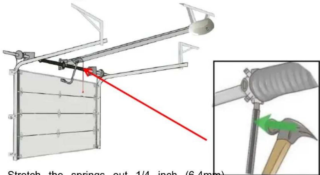
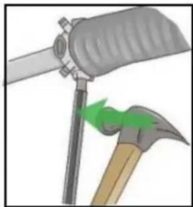
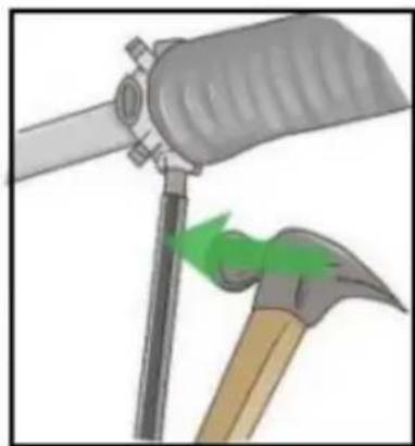
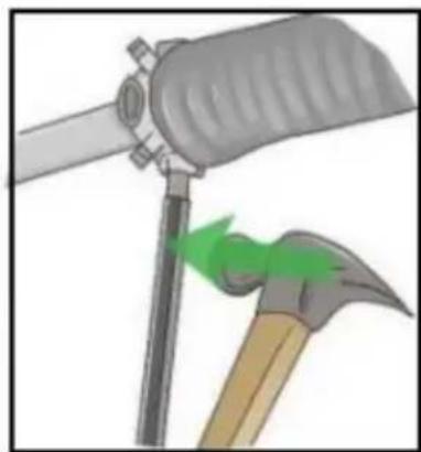
- Stretch the springs out 1/4 inch (6.4mm).
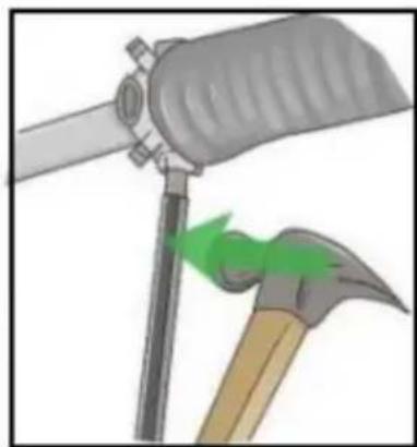
When the spring is fully wound, leave 1 winding bar in a slot of the cone perpendicular to the floor. Tap the winding bar with a hammer to stretch the 1/4 inch (6.4mm) out from the center. Repeat on the other side.
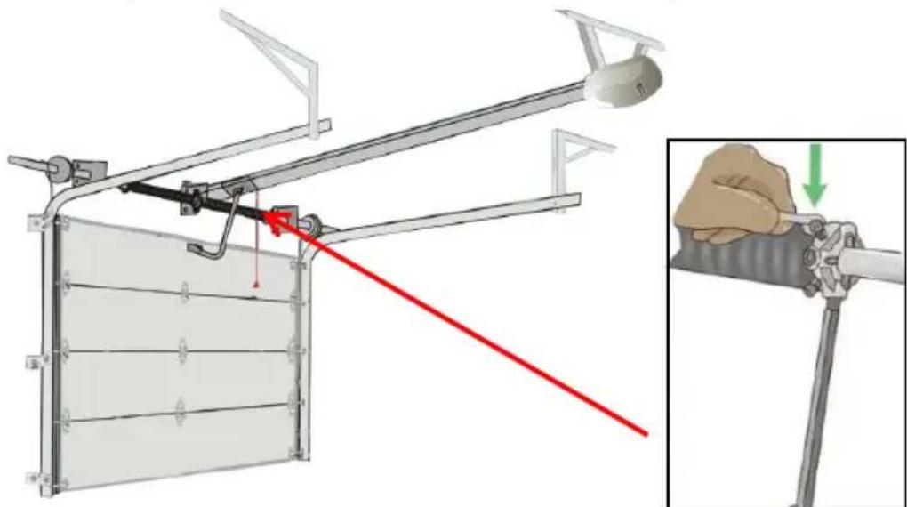
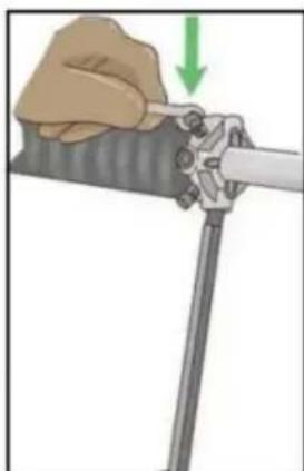
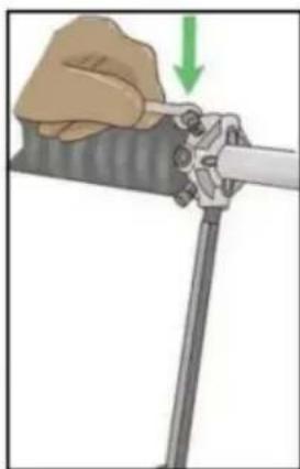
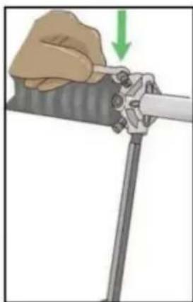
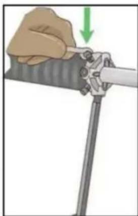
- Tighten the set screws.
Tighten each set screw until it contacts the torsion tube. Tightening the screw more than this could distort or puncture the torsion tube, so be sure to make no more than 1 full rotation once the screws touch the torsion tube.
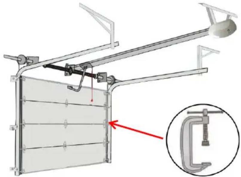
- Remove the clamps or pliers.
It is now safe to remove the clamps or pliers you used to hold both the torsion bar and the garage door itself in place.
Note: When you need to add or unwind 1 or 2 quarter turns, you must hold the clamps or pliers again.
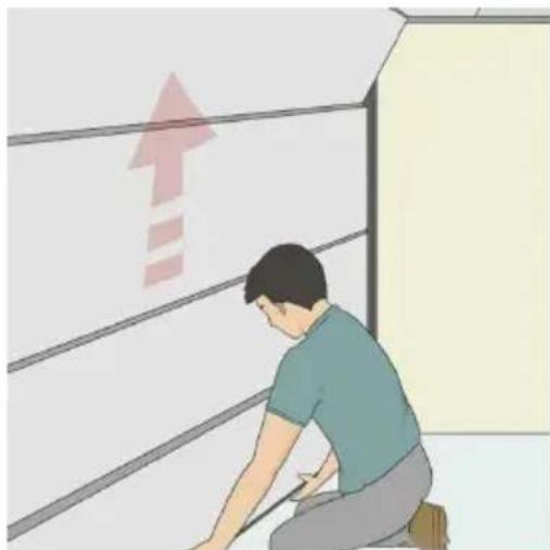
- Check the balance after installation.
Leave the door at half way position:
If the door moves up on its own, it means the torsion springs are wound too tight. In this case, unwind both torsion springs 1 or 2 quarter turns so the door balances itself.
MAINTENANCE
- Use a neutral cleaner and a soft brush to clean the garage door a few times a year.
- Use a lightweight oil spray on all springs, hinges, rollers and pivot points at least once a year to allow your garage door to slide smoothly up and down.
- Once a year, you should thoroughly inspect the electric garage door and tighten all screws, nuts or bolts that may be loose.
- Using a cloth and a concentrated but non-corrosive cleaner, wipe the garage door track and carefully clean all exposed parts of the roller to remove all excess moisture.
| EC | REP |
| UK | REP |
NEED HELP? CONTACT US!
REMOVING OLD SPRINGS
WARNING
- Tighten the springs.
Imported into AUS: SIHAO PTY LTD, 1 ROKEVA STREETEASTWOOD NSW 2122 Australia
C/O YH Consulting Limited Office 147, Centurion House, London Road, Staines-upon-Thames, Surrey, TW18 4AX
VEVOR®
TOUGH TOOLS, HALF PRICE
REMOVING THE OLD SPRINGS
WARNING
- Load the springs.
Imported into AUS: SIHAO PTY LTD, 1 ROKEVA STREETEASTWOOD
New South Wales 2122 Australia
NEED HELP? CONTACT US!
REMOVE THE OLD SPRINGS
WARNING
4. Find the springs.
8. Check the balance after installation.
YH CONSULTING LIMITED. C/O YH Consulting Limited Office 147, Centurion House, London Road, Staines-upon-Thames, Surrey, TW18 4AX
VEVOR®
TOUGH TOOLS, HALF PRICE
www.vevor.com/support
VEVOR®
TOUGH TOOLS, HALF PRICE
Technical support and e-warranty certificate www.vevor.com/support
GARAGE DOOR SPRING
MODEL: 207-2-24/250-2-35/225-2-27/250-2-31/234-2-28/234-2-31/250-2-32/218-2-26/225-2-24 GZ-22/GZ-23/GZ-24/GZ-28/GZ-29/GZ-30
NEED HELP? CONTACT US!
REMOVING THE OLD SPRINGS
WARNING
- Wind the springs.
- Tighten the adjusting screws.
- Check the balance after installation.
C/O YH Consulting Limited Office 147, Centurion House, London Road, Staines-upon-Thames, Surrey, TW18 4AX
VEVOR®
TOUGH TOOLS, HALF PRICE
warranty certificate www.vevor.com/support
VEVOR®
TOUGH TOOLS, HALF PRICE
NEED HELP? CONTACT US!
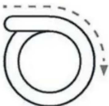
Right-hand rotation
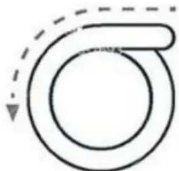
Left-hand rotation
REMOVAL OF OLD SPRINGS
WARNING
- Wind the springs.
C/O YH Consulting Limited Bureau 147, Centurion House, Route de Londres, Staines-upon-Thames, Surrey, TW18 4AX
VEVOR®
TOUGH TOOLS, HALF PRICE
YH CONSULTING LIMITED. C/O YH Consulting Limited Office 147, Centurion House, London Road, Staines-upon-Thames, Surrey, TW18 4AX
VEVOR®
TOUGH TOOLS, HALF PRICE
www.vevor.com/support
Brand : Vevor
Model : 225-2-27
Category : Garage door spring