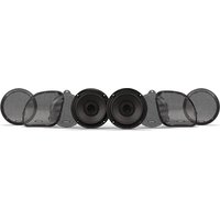
TMS14-65 - Loudspeaker Rockford Fosgate - Free user manual and instructions
Find the device manual for free TMS14-65 Rockford Fosgate in PDF.


| Product Type | Motorcycle replacement speaker |
| Brand | Rockford Fosgate |
| Model | TMS14-65 |
| Diameter | 6.5 inches (165 mm) |
| Impedance | 4 ohms |
| RMS Power | 50 watts |
| Max Power | 100 watts |
| Frequency Response | 50 Hz - 20 kHz |
| Sensitivity | 90 dB |
| Cone Material | Polypropylene with polyurethane dust cap |
| Suspension Material | Rubber |
| Magnet | Ferrite |
| Unit Weight | 0.5 kg |
| Included Accessories | Protective grilles, mounting hardware |
| Compatibility | Harley-Davidson 2014 and later (Ultra Classic, Electra Glide, Street Glide, Tri Glide, Road Glide, Road Glide Ultra) |
| Installation | Direct replacement for factory (OEM) speakers |
| Maintenance and Cleaning | Clean with a soft, dry cloth. Do not use abrasive solvents. |
| Safety | Disconnect battery before installation. Do not expose to prolonged sound levels >100 dB. |
| Spare Parts and Repairability | Grilles and hardware available. User repair not intended. |
| General Information | Designed for outdoor use on motorcycles. |
Frequently Asked Questions - TMS14-65 Rockford Fosgate
User questions about TMS14-65 Rockford Fosgate
0 question about this device. Answer the ones you know or ask your own.
Ask a new question about this device
Download the instructions for your Loudspeaker in PDF format for free! Find your manual TMS14-65 - Rockford Fosgate and take your electronic device back in hand. On this page are published all the documents necessary for the use of your device. TMS14-65 by Rockford Fosgate.
USER MANUAL TMS14-65 Rockford Fosgate
Installation assistance available at:
RFTECH
www.rockfordfosgate.com/rftech
TMS14-65

SCAN QR-CODE FOR:
Product Details • Specifications
Owners Manual • Installation Video

Rockford Fosgate
POWER
SPEAKERS FOR
2014-2023 HARLEY-DAVIDSON®
TMS14-65

Serial Number: Date of Purchase:
600 South Rockford Drive • Tempe, Arizona 85288 United States
Direct: (480) 967-3565 • Toll Free: (800) 669-9899
ROCKFORDFOSGATE.COM
CE

Rockford Fosgate.
Installation & Operation
Dear Customer,
Congratulations on your purchase of the world's finest brand of audio products. At Rockford Fosgate we are fanatics about musical reproduction at its best, and we are pleased you chose our product. Through years of engineering expertise, hand craftsmanship and critical testing procedures, we have created a wide range of products that reproduce music with all the clarity and richness you deserve.
For maximum performance we recommend you have your new Rockford Fosgate product installed by an Authorized Rockford Fosgate Dealer, as we provide specialized training through Rockford Technical Training Institute (RTTI). Please read your warranty and retain your receipt and original carton for possible future use.
Great product and competent installations are only a piece of the puzzle when it comes to your system. Make sure that your installer is using 100% authentic installation accessories from Rockford Fosgate in your installation. Rockford Fosgate has everything from RCA cables and speaker wire to power wire and battery connectors. Insist on it! After all, your new system deserves nothing but the best.
To add the finishing touch to your new Rockford Fosgate image, order your Rockford accessories, which include everything from T-shirts to hats.
Visit our web site for the latest information on all Rockford products;
www.rockfordfosgate.com
or, in the U.S. call 1-800-669-9899 or FAX 1-800-398-3985. For all other countries, call +001-480-967-3565 or FAX +001-480-966-3983.
Table of Contents
2 Introduction
3-6 Specifications
7 Installation Considerations
8-11 Installation
12 Français
13 Español
14 Deutsch
15 Italiano
16 Warranty
If, after reading your manual, you still have questions regarding this product, we recommend that you see your Rockford Fosgate dealer. If you need further assistance, you can call us direct at 1-800-669-9899. Be sure to have your serial number, model number and date of purchase available when you call.
PRACTICE SAFE SOUND
Continuous exposure to sound pressure levels over 100dB may cause permanent hearing loss. High powered auto sound systems may produce sound pressure levels well over 130dB. Use common sense and practice safe sound.
PRATIQUEZ UNE ÉCOUTE SANS RISQUES
This symbol with "WARNING" is intended to alert the user to the presence of important instructions. Failure to heed the instructions will result in severe injury or death.
This symbol with "CAUTION" is intended to alert the user to the presence of important instructions. Failure to heed the instructions can result in injury or unit damage.

WARNING

CAUTION
- To prevent injury and damage to the unit, please read and follow the instructions in this manual. We want you to enjoy this system, not get a headache.
- If you feel unsure about installing this system yourself, have it installed by a qualified Rockford Fosgate technician.
- Before installation, disconnect the battery negative (-) terminal to prevent damage to the unit, fire and/or possible injury.
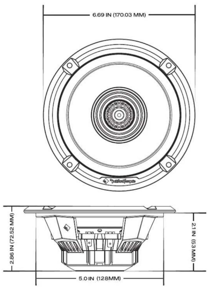
| Model | TMS14-65 |
| Nominal Diameter - inch (mm) | 6.5(165) |
| Description | 2-Way |
| Nominal Impedance (Ohms) | 4Ω |
| Frequency Response (Hz) | 50-20k |
| Voice Coil Diameter - inch (mm) | 1.5(38.6) |
| Power Handling - Watts (RMS/Peak) | 150/300 |
| Fs - Free Air Resonance (Hz) | 72.5 |
| Qts | 0.43 |
| Vas - cu. ft.(Liter) | 0.215(6.1) |
| Sensitivity (1W/1M) | 90.6dB |
| Sensitivity (2.83V/1M) | 93.6dB |
| Xmax - inch (mm) | 0.17(4.5) |
| Mounting Diameter | 5.0(128) |
| Mounting Depth | 2.1(53) |
| Grille/Trim Ring | YES |

IPX6 is the water ingress prevention rating of this product. Here's a breakdown of everything needed for the IPX6 test: A 0.5" (12.5mm) nozzle with 15 psi (100 kpa) outputting 100 liters/minute of water from a distance of 9.8' (3 meters) from all directions for at least 3 minutes.

CEA-2031
Power handling on Rockford Fosgate speakers conform to CEA-2031 industry standards. This means your speaker has the capacity to handle power under continuous demand, not instantaneous power handling that over time can damage voice coils.

VERIFIED WITH KLIPPEL
To adorn the 'Verified with Klippel' mark, the qualifying company's loudspeaker engineering personnel must be trained and certified by Klippel prior to using the three separate Klippel systems to design, develop and test. Rockford Fosgate has made the investment in Klippel to deliver the best possible speakers and subwoofers to their customers.
Contents
• (1) Pair of 2-Way Speakers
• (1) Pair of 2015 & Up Road Glide Grilles
• (1) Pair of 2014 & Up Street Glide Grilles
• (1) Pair of 2014 & Up Tour-Pak Grilles
• Installation & Operation Manual
- Kit may include (1) Pair of Spacer Rings for Tour-Pak.
Installation Tools
The following is a list of suggested tools needed for installation:
- Plastic Trim Panel Pry Tool
- Allen Wrench - 3/16", 5/32"
- Torx - T10, T25, T27
Installation Considerations
This section focuses on some considerations for installing your motorcycle replacement speakers. This manual will illustrate the installation of two different fairing styles and Tour-Pak offered by Harley-Davidson® from the production years ranging from 2014 and Up. (Ultra Classic®, Electra Glide®, Street Glide®, Tri Glide®, Road Glide® and Road Glide Ultra®.)
If you feel unsure about installing this system yourself, have it installed by a qualified technician.

CAUTION
Before installation, disconnect the battery negative (-) terminal to prevent damage to the unit, fire and/or possible injury.

CAUTION
Before beginning any installation, follow these simple rules:
- Be sure to carefully read and understand the instructions before attempting to install these motorcycle speakers.
- Consult your motorcycle's service manual for model specific information. Models may differ from year to year depending on factory options and aftermarket accessories added.
- These motorcycle speakers are a complete replacement to the factory (OEM) speaker setup.
- With the addition of an amplifier, be sure that your current charging system is in proper working order.
- Utilize a blanket or fender cover to protect the front fender from tools or any other item that may be accidentally be dropped while removing the fairing.
- Visit rockfordfosgate.com for more comprehensive installation videos and product information.
Front Speakers for Ultra Classic ^® , Electra Glide ^® , Street Glide ^® and Tri Glide ^® models.
natural_image
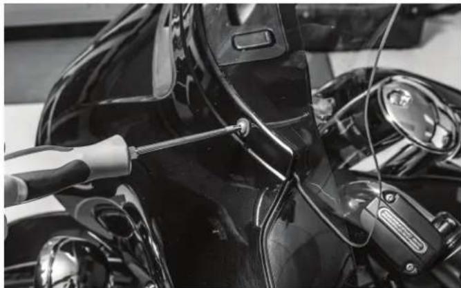
Close-up of a black motorcycle's front wheel and dashboard with visible wiring and sensor components (no text or symbols)Step 1 - Fairing Removal
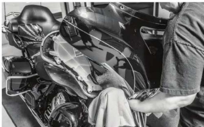
To begin with, remove the top screws below the windshield to remove the windshield.
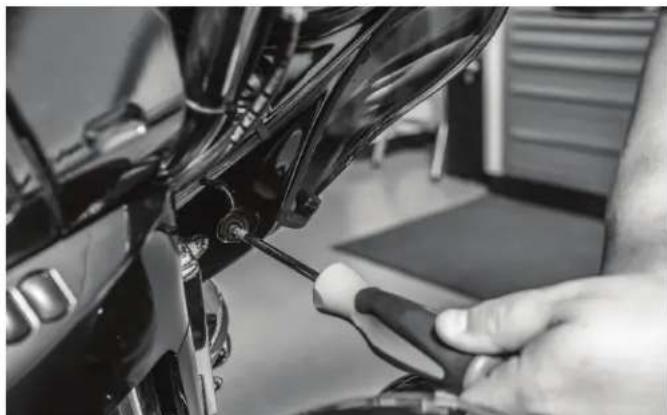
natural_image
Close-up of a hand using a tool to adjust or install a motorcycle component (no visible text or symbols)Once you have the windshield set aside, remove the remaining screws on the inside of the fairing.
natural_image
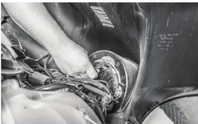
Person cleaning a motorcycle with visible tire marking and safety gear (no text or symbols)This will allow you to remove the front fairing.
natural_image
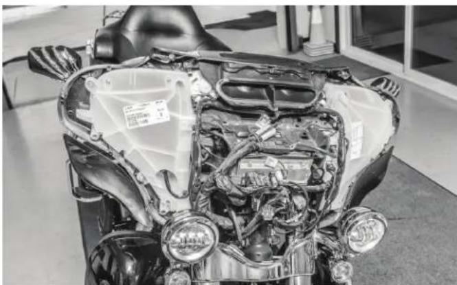
Close-up of hands installing or adjusting a car engine compartment with visible wiring and components (no text or symbols)You will need to disconnect the harness from the headlight to completely take the fairing off of the motorcycle.
natural_image
Close-up of a motorcycle's front engine compartment showing internal components and wiring (no visible text or symbols)Step 2 - Speaker & Pod Removal
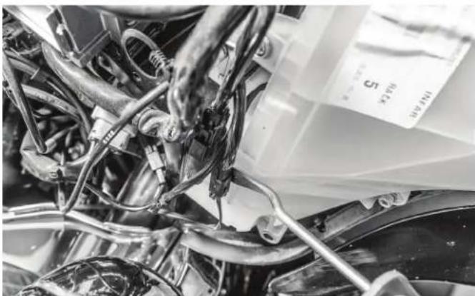
After the fairing is removed, this will provide access for the speaker pods that need to be removed so the speakers can be replaced.
natural_image
Close-up of mechanical components with wires and tubing, no visible text or symbolsThere are several wire connectors that are attached to the speaker pods and surrounding components that will need to be removed prior to unbolting allowing access to the bolts holding the pods in place.
natural_image
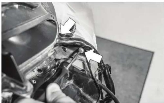
Close-up of a damaged mechanical component with visible wiring and two white arrows pointing to specific areas (no text or symbols present)Remove the top two bolts with a allen head screwdriver or ratchet.
natural_image
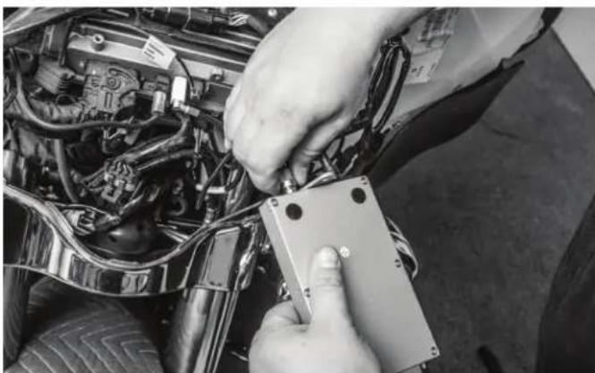
Close-up of hands installing or adjusting a mechanical component on an automotive engine compartment (no visible text or symbols)Unplug the module and set it aside.
natural_image
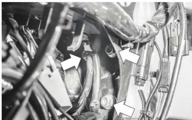
Close-up of mechanical components with white arrows pointing to specific parts (no visible text or symbols)After the top two bolts are removed, remove the three bolts that are under the radio area.
natural_image
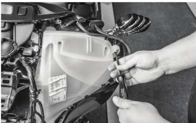
Close-up of a hand using a tool to clean or inspect the engine compartment of a car (no visible text or symbols)Next, remove the last three screws that hold the pod to the fairing.
natural_image
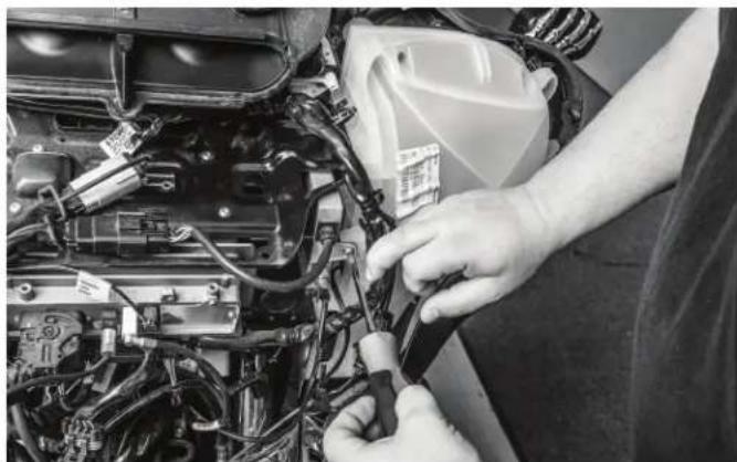
Close-up of hands installing or adjusting components on an engine compartment (no visible text or symbols)If your bike is equipped with the optional communication setup, you will need to remove the module to access mounting bolts.
natural_image
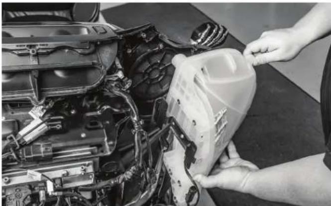
Close-up of hands pouring liquid into a plastic container on an engine compartment (no visible text or symbols)Remove the fairing and set aside for the speaker removal.
natural_image
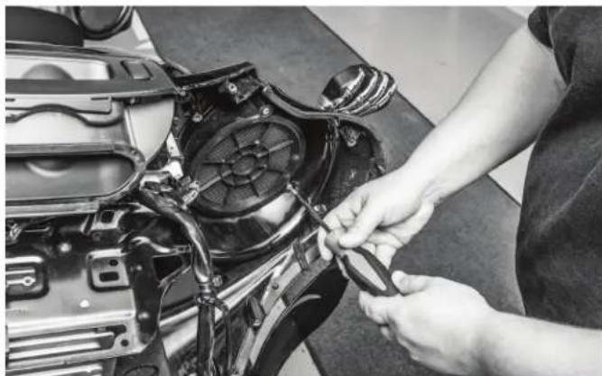
Person adjusting a car engine component with tools (no visible text or symbols)Using a screwdriver, remove the speaker grille that is attached to the fairing.
natural_image
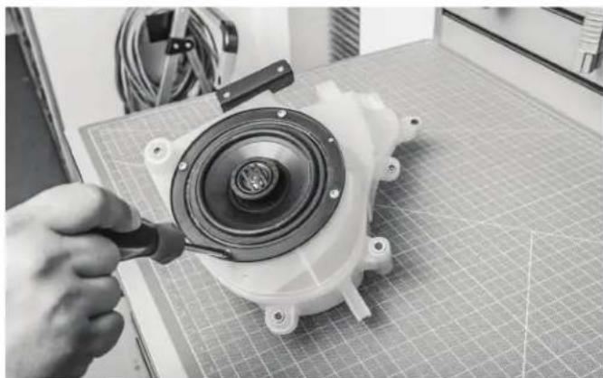
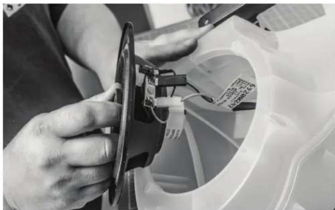
Hand holding a magnifying tool inspecting a white mechanical component on a grid cutting mat (no visible text or symbols)With the pod on a bench, unscrew the mounting screws to remove the factory speaker from the factory pod.
natural_image
Close-up of hands installing a mechanical component with a circular dial and cable, no visible text or symbolsUnplug the terminals to disconnect the speaker.

natural_image
Close-up of a hand adjusting a mechanical component with a white arrow pointing to a detail (no visible text or symbols)Step 3 - Speaker Installation
Prior to installing the speaker to the pod, there are alignment pins on the pod that the speaker needs to line up to ensure proper fit.
natural_image
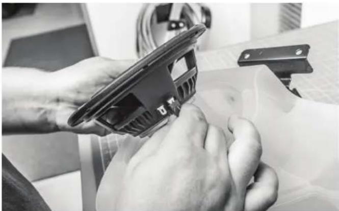
Close-up of hands holding a 3D-printed mechanical component, with a laptop and cable in the background (no visible text or symbols)Take the new Rockford speaker and slide the wire connectors over the terminals.
NOTE: The smaller terminal is the positive (+) and the larger terminal is the negative (-).
natural_image
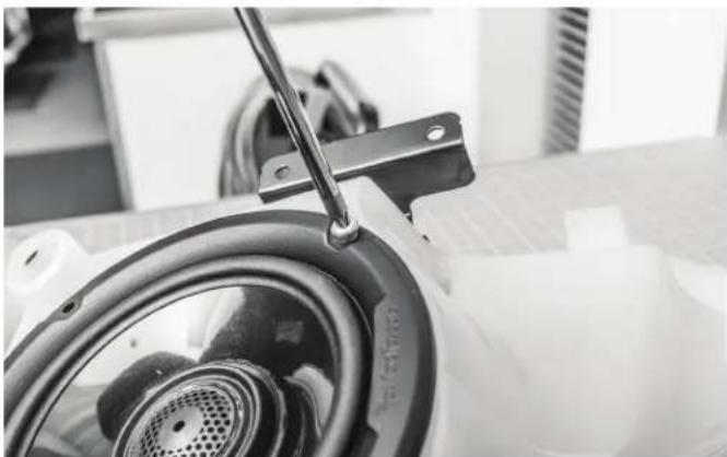
Close-up of a mechanical component with a tool inserted, showing a circular component and a ring (no visible text or symbols)Secure the speaker to the factory pod using the factory hardware. NOTE: Do not overtighten the mounting screws. Doing so can strip the threads on the plastic pod.
natural_image
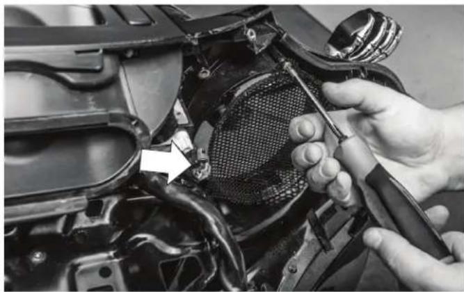
Close-up of hands installing or adjusting a mechanical component with a tool, no visible text or symbolsAttach the new Rockford grille to the inside of the fairing.
NOTE: The speaker grilles are side specific and have a notch in one of the mounting holes as an indicator. The notch is faced towards the middle of the bike.
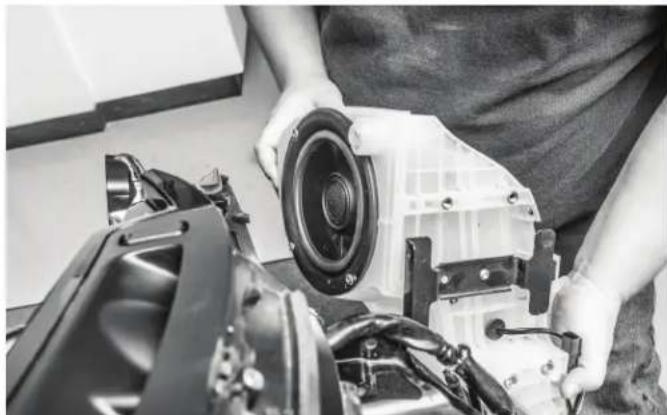
natural_image
Person assembling a mechanical component with a speaker and fan assembly (no visible text or symbols)Reattach the pod with the factory hardware and reinstall any wire harnesses that were removed for the pod removal.

natural_image
Close-up of a motorcycle's front wheel and side-mounted sensor array (no visible text or symbols)Install the outer fairing to the motorcycle after speaker pods and wiring is secured.

natural_image
Close-up of a hand adjusting a car grille with a circular light source (no visible text or symbols)Front Speakers for Road Glide® and Road Glide Ultra® models.
Step 1 - Speaker & Grille Removal
Remove the factory speaker grille with a plastic pry tool or small hook tool.

natural_image
Close-up of a hand inserting a fan into a motorcycle's seatbelt, showing no text or symbols.NOTE: Pull or pry on the portion of the grille that is closer to the inside of the bike.
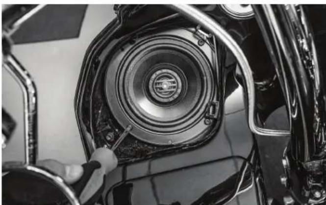
natural_image
Close-up of a car's front bumper with a circular speaker and screwdriver, no visible text or symbolsRemove the mounting screws holding the speaker in place.
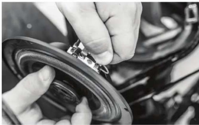
natural_image
Close-up of hands installing a mechanical component on a car wheel (no visible text or symbols)Unplug the terminals to disconnect the speaker.
Step 2 - Speaker & Grille Installation
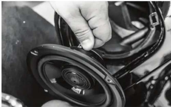
natural_image
Close-up of a hand adjusting a black plastic speaker wheel component (no visible text or symbols)Take the new Rockford speaker and slide the wire connectors over the terminals.
NOTE: The smaller terminal is the positive (+) and the larger terminal is the negative (-).

natural_image
Close-up of hands installing a circular mechanical component with a label (no visible text or symbols)Prior to installing the speaker to the pod, there are alignment pins on the pod that the speaker needs to line up to ensure proper fit.
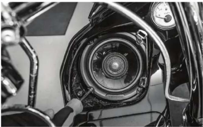
natural_image
Close-up of a motorcycle's front wheel assembly with a hand adjusting the component (no visible text or symbols)Secure the speaker to the pod using the factory hardware.
NOTE: Do not overtighten screws. Doing so can strip the threads on the plastic pod.
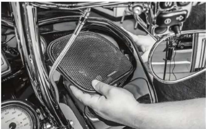
natural_image
Close-up of hands installing a mesh fan component on a motorcycle wheel (no visible text or symbols)Once the speaker is secured, press the new grille into place.
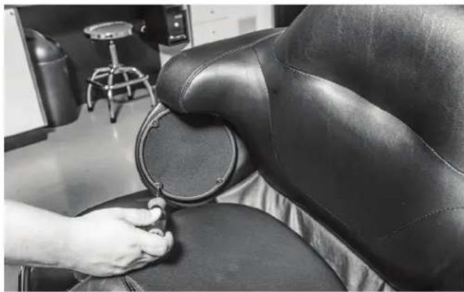
natural_image
Close-up of a person adjusting a black leather chair seat with a circular dial (no visible text or symbols)Rear Speakers for Tour-Pak models.
Step 1 - Rear Speaker Removal
Unscrew the speaker grilles from the rear pods and remove factory speaker.
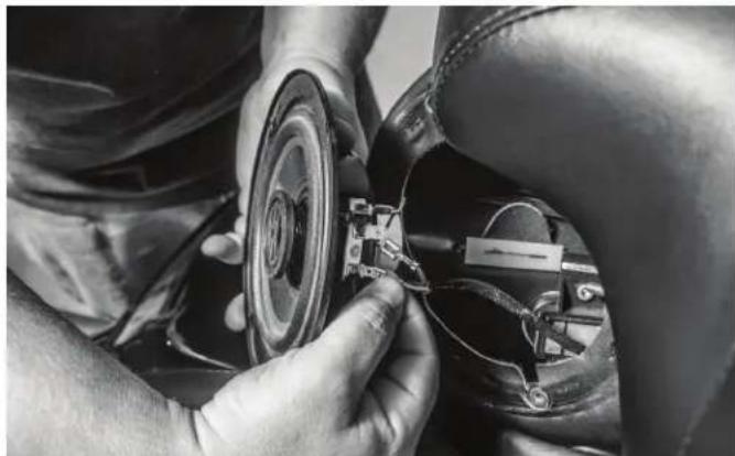
natural_image
Close-up of hands assembling a car interior with a circular component and wiring (no visible text or symbols)Unplug the terminals to disconnect the speaker.
natural_image
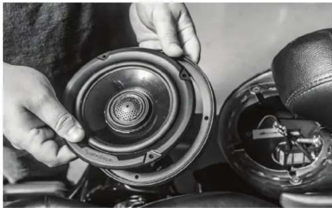
Close-up of hands installing a speaker into a car seatbelt, showing internal components and wiring (no text or symbols visible)Step 2 - Rear Speaker Installation
Before connecting the speaker wires, place the grille trim ring behind the speaker.
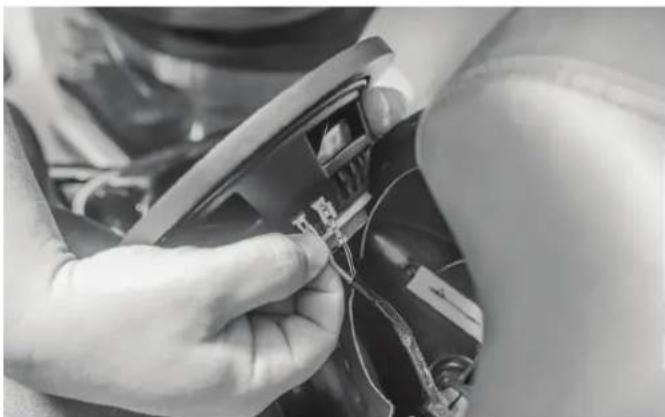
natural_image
Close-up of hands installing or adjusting a component with wires and connectors (no visible text or symbols)Connect the speakers by sliding the speaker wire connector over the speaker terminals
NOTE: The smaller terminal is the positive (+) and the larger terminal is the negative (-).
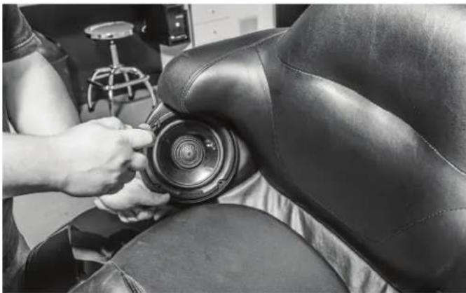
natural_image
Close-up of a person adjusting a camera lens on a black leather chair seat (no visible text or symbols)Insert the new Rockford speaker into the speaker pod and secure with mounting screws.
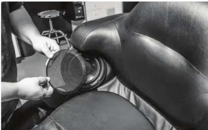
natural_image
Close-up of a person adjusting a black leather seat cover with a mesh filter (no visible text or symbols)Place the grille over the speaker and press into place.
Rockford Corporation offers a limited warranty on Rockford Fosgate products on the following terms: Length of Warranty
POWER Amplifiers – 2 Years
PUNCH ^® & PRIME ^® Amplifiers – 1 Year
Speakers, Signal Processors and Accessories – 1 Year
All marine, motorcycle and motorsports products – 2 Years
Any Factory Refurbished Product – 90 days
What is Covered
This warranty applies only to Rockford Fosgate products sold to consumers by Authorized Rockford Fosgate Dealers in the United States of America or its possessions. Product purchased by consumers from an Authorized Rockford Fosgate Dealer in another country are covered only by that country's Distributor and not by Rockford Corporation.
Who is Covered
This warranty covers only the original purchaser of Rockford product purchased from an Authorized Rockford Fosgate Dealer in the United States. In order to receive service, the purchaser must provide Rockford with a copy of the receipt stating the customer name, dealer name, product purchased and date of purchase.
Products found to be defective during the warranty period will be repaired or replaced (with a product deemed to be equivalent) at Rockford's discretion.
What is Not Covered
- Damage caused by accident, abuse, improper operations, water, theft, shipping.
- Any cost or expense related to the removal or reinstallation of product.
- Service performed by anyone other than Rockford or an Authorized Rockford Fosgate Service Center.
- Any product which has had the serial number defaced, altered, or removed.
- Subsequent damage to other components.
- Any product purchased outside the U.S.
- Any product not purchased from an Authorized Rockford Fosgate Dealer.
Limit on Implied Warranties
Any implied warranties including warranties of fitness for use and merchantability are limited in duration to the period of the express warranty set forth above. Some states do not allow limitations on the length of an implied warranty, so this limitation may not apply. No person is authorized to assume for Rockford Fosgate any other liability in connection with the sale of the product.
How to Obtain Service
Contact the Authorized Rockford Fosgate Dealer you purchased this product from. If you need further assistance, call 1-800-669-9899 for Rockford Customer Service. You must obtain an RA# (Return Authorization number) to return any product to Rockford Fosgate. You are responsible for shipment of product to Rockford.
EU Warranty
This product meets the current EU warranty requirements, see your Authorized dealer for details.

Rockford Fosgate
TMS14-65

SCAN QR-CODE FOR:
Product Details · Specifications Owners Manual · Installation Video
WARRANTY INFORMATION
Flip card over for more warranty details.
Serial Number: ____
Date of Purchase: ____
Rockford Fosgate
600 South Rockford Drive · Tempe, Arizona 85288 United States
Direct:(480)967-3565·Toll Free:(800)669-9899
Designed and Engineered in the U.S.A.
www.rockfordfosgate.com
NEED HELP WITH YOUR INSTALLATION?

YOUTUBE VISIT OUR CHANNEL FOR A COMPLETE INSTALLATION VIDEO AND OTHER TIPS WWW.YOUTUBE.COM/USER/ROCKFORDFOSGATE

TECH SUPPORT ROCKFORDFOSGATE.COM/SUPPORT 1-000-555-9898
- RFTECH
- Dear Customer,
- www.rockfordfosgate.com
- Table of Contents
- PRACTICE SAFE SOUND
- PRATIQUEZ UNE ÉCOUTE SANS RISQUES
- WARNING
- CAUTION
- CEA-2031
- VERIFIED WITH KLIPPEL
- Contents
- Installation Tools
- Installation Considerations
- Step 3 - Speaker Installation
- Step 1 - Speaker & Grille Removal
- Rear Speakers for Tour-Pak models.
- Step 1 - Rear Speaker Removal
- Step 2 - Rear Speaker Installation
- Rockford Corporation offers a limited warranty on Rockford Fosgate products on the following terms: Length of Warranty
- What is Covered
- Who is Covered
- What is Not Covered
- Limit on Implied Warranties
- How to Obtain Service
- EU Warranty
- Rockford Fosgate
- WARRANTY INFORMATION
- NEED HELP WITH YOUR INSTALLATION?
Brand : Rockford Fosgate
Model : TMS14-65
Category : Loudspeaker