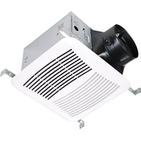
CEP110 - Ceiling extraction fan Canarm - Free user manual and instructions
Find the device manual for free CEP110 Canarm in PDF.


| Product Type | Ceiling Exhaust Fan |
| Brand | Canarm |
| Model | CEP110 |
| Power Supply | 120 V AC, 60 Hz |
| Intended Use | General ventilation, including over a bathtub or shower with GFCI protection |
| Ceiling Installation | Up to a 12/12 pitch (45 degree angle) |
| Maximum Ceiling Insulation | R40 |
| Duct Type | Round, with duct connector/damper included |
| Hanger Bars | Included, extendable up to 24 inches (61 cm) |
| Grille | Included, spring-loaded attachment |
| Motor | Permanently lubricated, maintenance-free |
| Grounding | Required |
| GFCI Protection | Recommended for use over a bathtub or shower |
| Prohibition | Do not use with a solid-state speed control device |
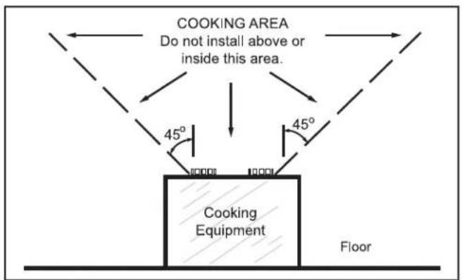
| Usage Prohibition | Do not use in a cooking area |
| Maintenance | Vacuum the interior with a brush after cutting off power |
| Main Replacement Parts | Motor, fan wheel, grille, hanger bars, duct connector |
| Warranty | 1 year against defects in material and workmanship |
| Standards to Follow | All applicable national, provincial, and local codes |
Frequently Asked Questions - CEP110 Canarm
User questions about CEP110 Canarm
0 question about this device. Answer the ones you know or ask your own.
Ask a new question about this device
Download the instructions for your Ceiling extraction fan in PDF format for free! Find your manual CEP110 - Canarm and take your electronic device back in hand. On this page are published all the documents necessary for the use of your device. CEP110 by Canarm.
USER MANUAL CEP110 Canarm
PLEASE READ AND SAVE THESE INSTRUCTIONS

CANARM®
HVAC
MODELS: CEP80, CEP110, CEP150
The purpose of this manual is to aid in the proper installation and operation of the CEP Series ceiling exhaust fans. These instructions are intended to supplement good general practices and are not intended to overwrite local codes and ordinances.
IT IS THE RESPONSIBILITY OF THE PURCHASER TO ENSURE THAT THE INSTALLATION AND MAINTENANCE OF THIS EQUIPMENT IS HANDLED BY QUALIFIED PERSONNEL.
Inspect all shipments carefully for damage. THE RECEIVER MUST NOTE ANY DAMAGE ON THE CARRIER'S BILL OF LADING AND FILE A CLAIM IMMEDIATELY WITH THE FREIGHT COMPANY.
GENERAL SAFETY
- Use this unit only in the manner intended by the manufacturer. If you have questions, contact the manufacturer at the address or telephone number listed in the warranty.
- Before servicing or cleaning unit, switch power off at service panel and lock the service disconnecting means to prevent power from being switching on accidentally. When the service disconnecting means cannot be locked, securely fasten a prominent warning device, such as a tag, to the service panel.
- Installation work and electrical wiring must be done by a qualified person(s) in accordance with all applicable codes and standards, including fire-rated construction codes and standards.
- Sufficient air is needed for proper combustion and exhausting of gases through the flue (chimney) of fuel burning equipment to prevent backdrafting. Follow the heating equipment manufacturer's guideline and safety standards such as those published by the National Fire Protection Association (NFPA), and the American Society for Heating, Refrigeration and Air Conditioning Engineers (ASHRAE), and the local code authorities.
- When cutting or drilling into wall or ceiling, do not damage electrical wiring and other hidden utilities. Ducted fans must always be vented to the outdoors. 6.
- Acceptable for use over a tub or shower when connected to a GFCI (Ground Fault Circuit Interrupter) - protected branch circuit. This unit must be grounded. 8.
- For general ventilating use only. Do not use to exhaust hazardous or explosive materials and vapors.
- This product is designed for installation in ceilings up to a 12/12 pitch (45 degree angle). Duct connector must point up.
- To avoid motor bearing damage and noisy and/or unbalanced impellers, keep drywall spray, construction dust, etc. off power unit. Please read specification label on product for further information and requirements. 12. Do not use in a cooking area. 13.
- WARNING: To Reduce The Risk Of Fire Or Electric Shock, Do Not Use This Fan With Any Solid-State Speed Control Device. The fan must not be installed in a ceiling thermally insulated to a value greater than R40. 15.
- Please follow all applicable national, state/provincial and local codes. All of them will supersede this manual.
- Failure to follow the safety instructions in this manual may cause serious injury or death due to electrical shock or high speed rotating parts.
CLEANING AND MAINTENANCE
For quiet and efficient operation, long life, and attractive appearance - lower or remove grille and vacuum interior of unit with the dusting brush attachment.
The motor is permanently lubricated and never needs oiling. If the motor bearings are making excessive or unusual noises, replace the motor with the exact service motor. The impeller should also be replaced.
OPERATION
Use an on/off switch to operate this fan. See Electrical Wiring Connection section for details.
PLAN THE INSTALLATION
- Do not use in a cooking area.
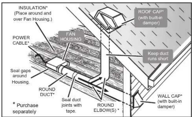
- Two ways to connect ductwork to a factory-shipped unit.
ASSEMBLY INSTRUCTIONS
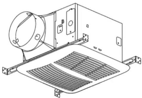
- Sliding hanger bars have been provided, which allow the housing to be positioned accurately anywhere between the framing. The bars span up to 24 inches and can be used on all types of framing: I-joist, standard joist, and truss construction. Slide hanger bars onto housing and adjust as needed to fit between framing.
- Extend the hanger bars to the width of the framing. Position the ventilator with the bottom edge of the hanger bar tabs flush with the bottom edge of the framing, holding the ventilator in place. Secure hanger bars to framing using one screw on each end of hanger bar. Select a proper hole and secure the hanger bars together using one screw.
- Install round ductwork. Connect the round ductwork (not included) to the damper/duct connector, and run the ductwork to a roof or wall cap (not included). Using tape (not included), secure all the ductwork connections so that they are air tight. The ducting from this fan to the outside of building has a strong effect on the air flow, noise and energy use of the fan. Use the shortest, straightest duct routing possible for best performance, and avoid installing the fan with smaller ducts than recommended. Insulation around the ducts can reduce energy loss and inhibit mold growth. Fans installed with existing ducts may not achieve their rated air flow.
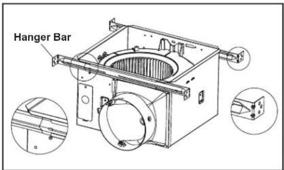
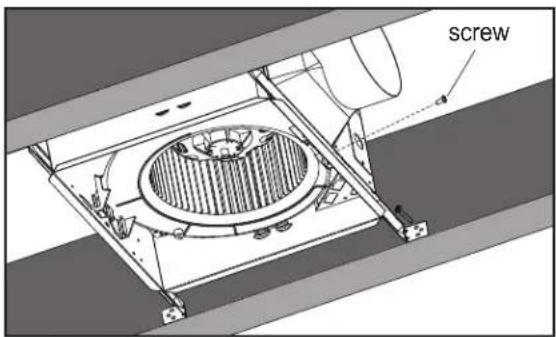
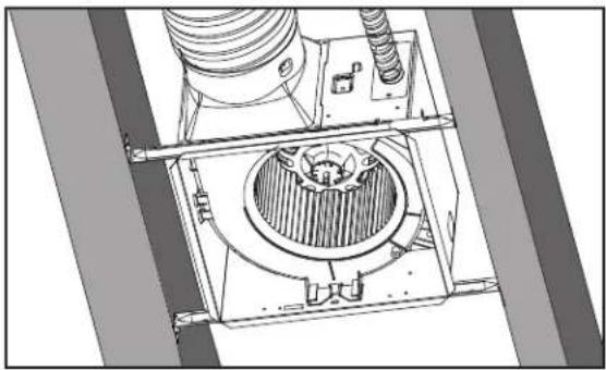
ELECTRICAL WIRING CONNECTION
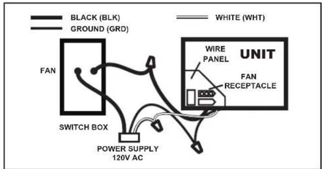
Run 120 V AC house wiring to the location of the fan. Use only UL-approved connectors (not included) to attach the house wiring to the wiring plate. Refer to the wiring diagram, and connect the wires as shown.
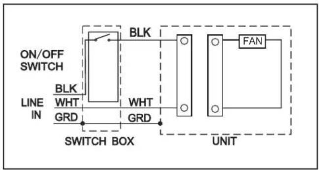
GRILLE INSTALLATION
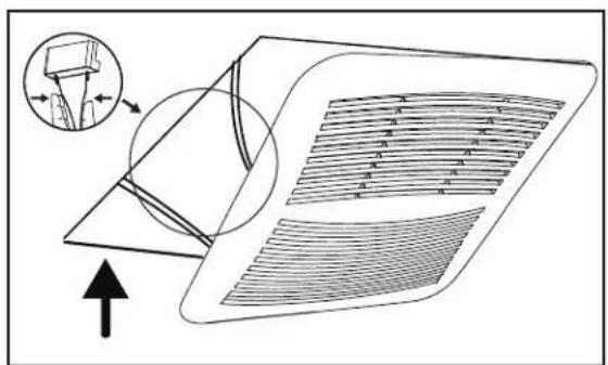
Install ceiling material to complete the ceiling construction. Then, cut around the fan housing.
To attach the grille assembly to the fan housing. Pinch the grille springs on the sides of the grille assembly, and position the grille into the housing with the grille springs in the appropriate slots. Push the grille assembly towards the ceiling to secure.
SERVICE PARTS
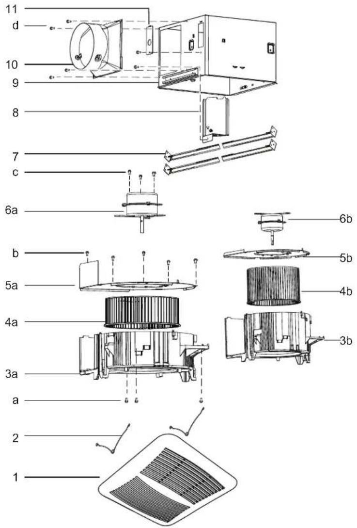
| PARTPART NAMEQTY | ||
| 1Grille Assembly (2 parts)1 | ||
| 2Grille Spring2 | ||
| 3aBlower1 | ||
| 4aBlower Wheel1 | ||
| 5aMotor Plate1 | ||
| 6aMotor1 | ||
| 3bBlower1 | ||
| 4bBlower Wheel1 | ||
| 5bMotor Plate1 | ||
| 6bMotor1 | ||
| 7Hanger Bar Kit4 | ||
| 8 | Wire Panel / Harness Assembly | 1 |
| 9Housing | 1 | |
| 10Damper / Duct Connector | 1 | |
| 11Wiring Plate | 1 | |
| a | Screw | 3 |
| b | Screw | 5 |
| cScrew | 3 | |
| d | Screw | 6 |
Blower Assembly includes part 3, 4, 5, 6, a, b, c
WARNING: Ensure that the fan is switched off from the supply mains before replacing.
WARRANTY
CANARM Ltd. warrants every new fan to be free of defects in material and workmanship to the extent that, within a period of one year from the date of purchase CANARM Ltd. shall either repair or replace at CANARM's option, any unit or part thereof, returned freight prepaid and found to be defective.
This warranty does not include any labour or transportation costs incidental to the removal and reinstallation of the unit at the user's premises.
NOTICE: No warranty claims will be honored by CANARM Ltd. unless prior authorization is obtained.
SÉRIE CEP
VENTILATEUR D'EXTRACTION DE PLAFOND ULTRA SILENCIEUX
MODE D'OPÉRATION
LIRE ET GARDER CES INSTRUCTIONS

CANARM®
HVAC
MODÈLES: CEP80, CEP110, CEP150
OPÉRATION
CONNEXION DU CÂBLAGE ÉLECTRIQUE
PIÈCES DE RECHANGE
Brand : Canarm
Model : CEP110
Category : Ceiling extraction fan