
ECU-150 - Electronic control unit Advantech - Free user manual and instructions
Find the device manual for free ECU-150 Advantech in PDF.

| Product type | Electronic control unit |
| Brand | Advantech |
| Model | ECU-150 |
| Power supply | 10-30 VDC, 1.5-0.5 A (UL or SELV certified source) |
| Storage temperature | -30 °C to 70 °C |
| Operating environment | Indoor, non-polluted, protected from moisture |
| Main functions | Electronic control, remote management via SSH, network communication |
| Management interface | SSH; default username and password (see manual) |
| Safety | Do not open; replace battery only with identical type; do not use in presence of children |
| Maintenance and cleaning | Disconnect before cleaning; use a damp cloth without detergent |
| Spare parts and repairability | No user-serviceable parts; return to manufacturer for repair |
| General information | Free PDF manual available (28 pages) |
Frequently Asked Questions - ECU-150 Advantech
User questions about ECU-150 Advantech
0 question about this device. Answer the ones you know or ask your own.
Ask a new question about this device
Download the instructions for your Electronic control unit in PDF format for free! Find your manual ECU-150 - Advantech and take your electronic device back in hand. On this page are published all the documents necessary for the use of your device. ECU-150 by Advantech.
USER MANUAL ECU-150 Advantech
natural_image
Illustration of three stacked electronic devices with no visible text or symbolsECU-150 Series
Copyright
The documentation and the software included with this product are copyrighted 2024 by Advantech Co., Ltd. All rights are reserved. Advantech Co., Ltd. reserves the right to make improvements in the products described in this manual at any time without notice. No part of this manual may be reproduced, copied, translated, or transmitted in any form or by any means without the prior written permission of Advantech Co., Ltd. The information provided in this manual is intended to be accurate and reliable. However, Advantech Co., Ltd. assumes no responsibility for its use, nor for any infringements of the rights of third parties that may result from its use.
Acknowledgments
Intel, Pentium, Celeron and Atom are trademarks of Intel Corporation.
Microsoft Windows and MS-DOS are registered trademarks of Microsoft Corp.
All other product names or trademarks are properties of their respective owners.
Support
For more information on this and other Advantech products, please visit our websites at: http://www.advantech.com
For technical support and service, please visit our support website at: http://www.advantech.com/support/
This manual is for ECU-150 Series.
Part No.2003U15000 Edition 1
Printed in China May 2024
Declaration of Conformity
CE
This product has passed the CE test for environmental specifications when shielded cables are used for external wiring. We recommend the use of shielded cables. This type of cable is available from Advantech. Please contact your local supplier for ordering information.
Test conditions for passing also include the equipment being operated within an industrial enclosure. In order to protect the product from damage caused by electrostatic discharge (ESD) and EMI leakage, we strongly recommend the use of CE-compliant industrial enclosure products.
FCC Class A
This equipment has been tested and found to comply with the limits for a Class A digital device, pursuant to part 15 of the FCC Rules. These limits are designed to provide reasonable protection against harmful interference when the equipment is operated in a commercial environment. This equipment generates, uses, and can radiate radio frequency energy and, if not installed and used in accordance with the instruction manual, may cause harmful interference to radio communications. Operation of this equipment in a residential area is likely to cause harmful interference. In this event, users are required to correct the interference at their own expense.
Technical Support and Assistance
- Visit the Advantech website at www.advantech.com/support to obtain the latest product information.
- Contact your distributor, sales representative, or Advantech's customer service center for technical support if you need additional assistance. Please have the following information ready before calling:
– Product name and serial number
– Description of your peripheral attachments
– Description of your software (operating system, version, application software, etc.)
– A complete description of the problem
– The exact wording of any error messages
Safety Precaution - Static Electricity
Follow these simple precautions to protect yourself from harm and the products from damage.
To avoid electrical shock, always disconnect the power from the PC chassis before manual handling. Do not touch any components on the CPU card or other cards while the PC is powered on.
- Disconnect the power before making any configuration changes. A sudden rush of power after connecting a jumper or installing a card may damage sensitive electronic components.
Safety Instructions
- Read these safety instructions carefully.
- Retain this user manual for future reference.
- Disconnect the equipment from all power outlets before cleaning. Use only a damp cloth for cleaning. Do not use liquid or spray detergents.
-
For pluggable equipment, the power outlet socket must be located near the equipment and easily accessible.
-
Protect the equipment from humidity.
-
Place the equipment on a reliable surface during installation. Dropping or letting the equipment fall may cause damage.
-
The openings on the enclosure are for air convection. Protect the equipment from overheating. Do not cover the openings.
-
Ensure that the voltage of the power source is correct before connecting the equipment to a power outlet.
-
Position the power cord away from high-traffic areas. Do not place anything over the power cord.
-
All cautions and warnings on the equipment should be noted.
-
If the equipment is not used for a long time, disconnect it from the power source to avoid damage from transient overvoltage.
-
Never pour liquid into an opening. This may cause fire or electrical shock.
-
Never open the equipment. For safety reasons, the equipment should be opened only by qualified service personnel.
-
If any of the following occurs, have the equipment checked by service personnel:
-
The power cord or plug is damaged.
– Liquid has penetrated the equipment.
– The equipment has been exposed to moisture. -
The equipment is malfunctioning, or does not operate according to the user manual.
– The equipment has been dropped and damaged.
– The equipment shows obvious signs of breakage. -
DO NOT LEAVE THIS EQUIPMENT IN AN ENVIRONMENT WHERE THE STORAGE TEMPERATURE MAY GO BELOW -30°C (-22°F) OR ABOVE 70°C (158°F). THIS COULD DAMAGE THE EQUIPMENT. THE EQUIPMENT SHOULD BE IN A CONTROLLED ENVIRONMENT.
-
CAUTION: DANGER OF EXPLOSION IF BATTERY IS INCORRECTLY REPLACED. REPLACE ONLY WITH THE SAME OR EQUIVALENT TYPE RECOMMENDED BY THE MANUFACTURER, DISCARD USED BATTERIES ACCORDING TO THE MANUFACTURER'S INSTRUCTIONS.
-
This product is intended to be supplied by an UL certified power supply or dc source with SELV output, rated 10 to 30Vdc, 1.5 to 0.5A minimum and maximum ambient temperature (Tma) 70 degree C minimum without power source or adapter. If you need further assistance, please contact Advantech for further information.
-
Ensure that the voltage of the power source is correct before connecting the equipment to a power outlet. The power outlet socket should have a grounded connection.
-
For use in pollution free environments and indoor use.
-
This equipment is not suitable for use in locations where children are likely to be present.
-
If the equipment is used in a manner not specified by the Advantech, the protection provided by the equipment may be impaired.
- The equipment contains no user-serviceable parts. Do not open, Return to manufacturer for servicing.
- Do not block air ventilation holes.
- This is open type equipment and should be installed in a suitable enclosure.
- Equipment is intended for installation in Restricted Access Area.
Chapter 2 Hardware Functionality......7
2.1 Overview 8
Figure 2.1 ECU-150 Overview....8
2.2 LED Status Indicators 9
Figure 2.2 ECU-150 LED Status Indicator....9
2.2.1 System Status Indicators: 9
2.2.2 Serial Communication Status Indicator.... 10
2.2.3 Ethernet Status Indicator 10
Chapter 3 Wiring and Installation .....11
3.1 Wiring.... 12
3.1.1 Power Supply Wiring.... 12
Figure 3.1 Power Supply Wiring 12
Table 3.1: DC Power Input Connector Pin Definition ..... 12
3.1.2 Communication Ports.... 12
Figure 3.2 RS-232/485 Serial Ports (COM1\~ COM2).... 12
Table 3.2: RS-232/485 Serial Ports (Pin Assignments)..... 12
3.1.3 USB Port.... 13
Figure 3.3 USB Connector.... 13
Table 3.3: USB Connector Pin Assignment.... 13
3.1.4 LAN Port 13
Figure 3.4 LAN Connectors (LAN1\~LAN2).... 13
Table 3.4: LAN Connector Pin Assignments 13
3.1.5 Console Port 14
Figure 3.5 Console Port of ECU-150-12A 14
Table 3.5: 3-Pin COM Assignments ..... 14
Figure 3.6 Console Port of ECU-150-12A1 14
3.1.6 SD&SIM Card Installation 15
Figure 3.7 SIM & SD Card Slot.... 15
er Setting.... 15
3.2.1 Jumper Setting.... 15
Figure 3.8 Jumper Setting 15
Table 3.6: Jumper Setting of Terminal Resistor For COM(1\~4) 16
sion and Installation 16
3.3.1 Extension Socket and Expansion Module List.... 16
Figure 3.9 Extension Socket.... 16
Table 3.7: Expansion Modules.... 17
Figure 3.10 Expansion Modules.... 17
3.3.2 Assembly of Expansion Module.... 17 Figure 3.11Assembly of Expansion Module .... 17
3.3.3 Wall-mounted and DIN-Rail Installation.... 18 Figure 3.12Wall-mount and DIN-Rail Installation .... 18
3.3.4 Installing a Wireless module Card and Antenna (Optional)...... 19 Figure 3.13Installing a Wireless module Card and Antenna ...... 19
Chapter 1
Overview
1.1 Introduction
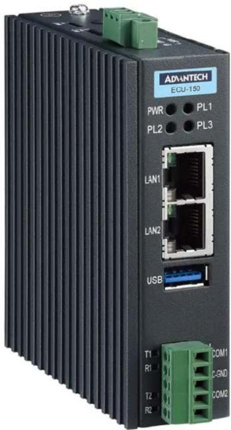
The ECU-150 is a high-performance IoT gateway based on the i.MX8M platform. It features an open design with a Quad Core processor, two isolated RS-232/485 serial ports, two 10/100/1000 Ethernet ports, one USB 3.0 port, and an operating temperature range of -40 to 70°C. It offers Mini-PCIe and various expansion options for integrating Wi-Fi, LTE, 4G, 5G, and iDoor modules. Running on a Linux operating system with EdgeLink, the ECU-150 allows system integrators to develop applications specifically for solar power, electricity, and factory settings, which require extensive data collection, cloud-based applications, and video monitoring solutions.
1.2 Specifications:
1.2.1 General
■ Certification: CE, FCC, UL
■ Mounting: Wall-Mount/ DIN-Rail
■ Power Consumption: 8W @ 24V DC
■ Power Requirements: 10 \~ 30 V DC
■ Dimensions (W x D x H): Basic Unit: 30 x 100 x 93mm
Double Stack: 55.1 x 100 x 93mm
■ Enclosure: Aluminum Housing
■ Operating System: Yocto 4.14/Ubuntu 22.04
1.2.2 System
■ CPU: NXP i.MX8M Quad Core Cortex A53 1.3G
■ Memory: LPDDR4 2/4GB
■ Storage: eMMC 16/32GB
■ Indicators: LEDs for Power, LAN (LINK, ACT), Serial (Tx, Rx), Programmable
■ Display: N/A (optional 1 x HDMI resolution 1280 x 720)
■ SD Slot: 1 x Micro-SD slot
■ SIM Slot: 1 x Nano SIM slot
■ Watchdog: Yes
RTC: Yes
■ Security: TPM2.0
■ FRAM: N/A (optional 128KB)
1.2.3 Communication
Serial Port: 2 x RS-232/485, 50 \~ 115200 bps
Isolation: 2500 V DC
- Ethernet Port: 2 x 10/100/1000 RJ-45 ports
USB Port: 1 x USB3.0
Console Port:
- 3-pin COM (ECU-150-12A)
- Micro-USB (ECU-150-12A1)
■ Expansion:
- Interface: 1 x Mini-PCIe (Full-size)
- Type: WIFI/Cellular/4G
– Signal: USB 2.0 (Optional PCIe)
1.2.4 Environment
■ Operating Temperature: -40 \~ 70°C
■ Storage Temperature: -40\~85°C
■ Humidity: 5\~95% (non-condensing)
1.2.5 SSH Login User Name & Password
■ User Name: root
■ Password: no password (press "Enter")
1.2.6 Default IP
■ LAN1: 10.0.0.1
■ LAN2: 11.0.0.1
1.2.7 Software
Protocol Support
| SouthBound NorthBound |
| IEC 60870-5-101 Modbus Server |
| IEC 60870-5-103 IEC 60870-104 Server |
| IEC 60870-5-104 WASCADA (WebAccess) |
| DL/T 645-2007 BACnet Server |
| DL/T 645-1997 OPC UA Server |
| IEC 62056-21 Data Transfer |
| ODBC |
| JDBC |
| OPCUA Client |
| BACnet IP |
| BACnet MS/TP |
| SNMP |
| Modbus Client |
PLC driver support: ABB/Advantech/Allen-Bradley/BECKHOFF/ DELTA/FATEK/GE/Honeywell/Keyence/Mitsubishi/Omron/Panasonic/Schneider/Sharp/Siemens/Toyopuc/Wago 750/Yaskawa/Yokogawa
■ Programming: IEC-61131-3, Linux C, Python
Configuration Tool: EdgeLink Studio*(ECU-150-12A)
■ Data Monitoring: 20000 Tags MAX.
Cloud Connectivity(MQTT): EdgeSync 360, WISE-PaaS, Azure, AWS, Google Cloud IoT Core and more
■ Database Transmission: SQL Server, MySQL, ORACLE, FTP Server
■ VPN: OpenVPN, L2TP over IPSec
* EdgeLink is bundled with Yocto Linux version. Please refer to EdgeLink specification for more details.
1.3 Safety Precautions
The following messages informs how to make each connection. In most cases, you will simply need to connect a standard cable
Warning! Always disconnect the power cord from your chassis whenever you are working on it. Do not connect while the power is on. A sudden rush of power can damage sensitive electronic components. Only experienced electronics personnel should open the chassis.
Caution! Always ground yourself to remove any static electric charge before touching ECU-150 Series. Modern electronic devices are very sensitive to static electric charges. Use a grounding wrist strap at all times. Place all electronic components on a static-dissipative surface or in a static-shielded bag.

Note! If DC voltage is supplied by an external circuit, please put a protection device in the power supply input port.

1.4 Chassis Dimensions
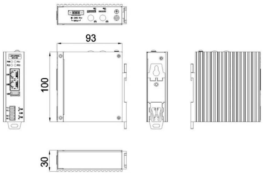
Figure 1.1 ECU-150 Chassis Dimensions
1.5 Packing List
The accessory package of ECU-150 contains the following items:
(A) ECU-150
(B) Warranty card
(C) RoHS
(D) Connector
(E) Din-rail
Chapter 2
Hardware
Functionality
2.1 Overview
The following figures show the panel configuration on ECU-150. More information of each peripheral is included in the following sections.
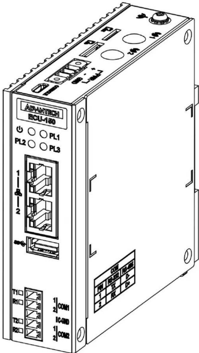
Figure 2.1 ECU-150 Overview
2.2 LED Status Indicators
The LEDs in the front panel can be divided into 3 groups:
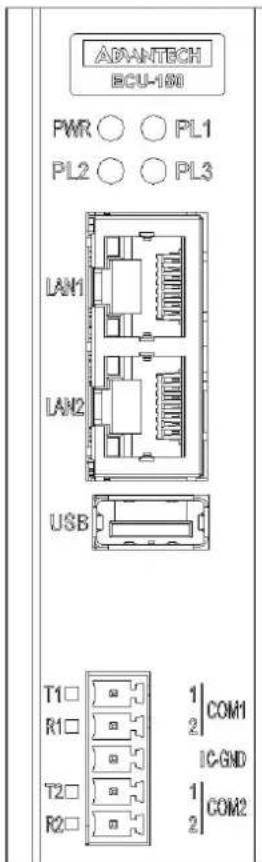
Figure 2.2 ECU-150 LED Status Indicator
2.2.1 System Status Indicators:

| LED Status Description | ||
| PWR | Green Power is on | |
| Off Power is off | ||
| PLx | Green | Customers can define the Programmable LED state according to the actual need. |
| Off | ||
2.2.2 Serial Communication Status Indicator
LED Color Description
| TX1 Orange Blinking, Serial port 1 data being transmitted |
| RX1 Green Blinking, Serial port 1 data being received |
| TX2 Orange Blinking, Serial port 2 data being transmitted |
| RX2 Green Blinking, Serial port 2 data being received |
2.2.3 Ethernet Status Indicator
LED Color Description
| Link1 Yellow Lighting, Ethernet not connected |
| Act1 Green Blinking, Ethernet data being transmitted |
| Link2 Yellow Lighting, Ethernet not connected |
| Act2 Green Blinking, Ethernet data being transmitted |
Chapter 3
Wiring and Installation
3.1 Wiring
3.1.1 Power Supply Wiring
ECU-150 supports power input ranging from and 10V_DC to 30V_DC . The terminal block is suitable for 16-26 AWG, Torque value 3 Lb In. Use copper conductors only. Must be installed by skilled personnel.

Figure 3.1 Power Supply Wiring
Table 3.1: DC Power Input Connector Pin Definition
| Function Pin Screen Printing Function Description | |
| Power Input | 1 + PWR V+ DC power input PIN |
| 2 - PWR V- DC power input PIN | |
| 3 GND GND | |
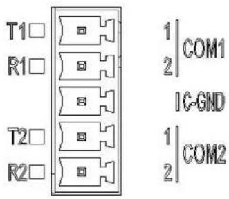
3.1.2 Communication Ports
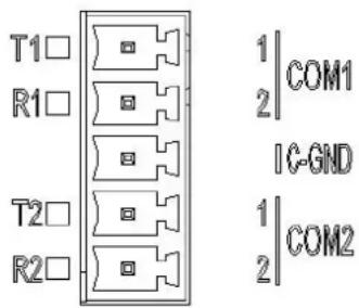
Figure 3.2 RS-232/485 Serial Ports (COM1\~ COM2)
Table 3.2: RS-232/485 Serial Ports (Pin Assignments)
| Pins | 1 | 2 | 3 |
| RS-232 | Tx Rx | GND | |
| RS-485 | Data- | Data+ | GND |
3.1.3 USB Port
ECU-150 is equipped with one USB 3.0 Type A port for optional extension choice.
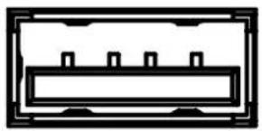
natural_image
Pure electrical circuit lines without any symbolsFigure 3.3 USB Connector
Table 3.3: USB Connector Pin Assignment
| Pin Signal |
| 1 VCC |
| 2 DATA- |
| 3 DATA+ |
| 4 GND |
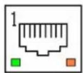
3.1.4 LAN Port
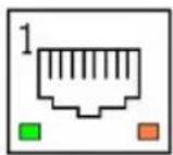
Figure 3.4 LAN Connectors (LAN1\~LAN2)
Table 3.4: LAN Connector Pin Assignments
| Pin Assignment Description |
| 1 TD+ Transmit+ |
| 2 TD- Transmit- |
| 3 RD+ Receive+ |
| 4 N/C Not used |
| 5 N/C N/C |
| 6 RD- Receive- |
| 7 N/C N/C |
| 8 N/C N/C |
3.1.5 Console Port
ECU-150 is equipped with a 3-Pin COM or Micro-USB port as console port for debugging.
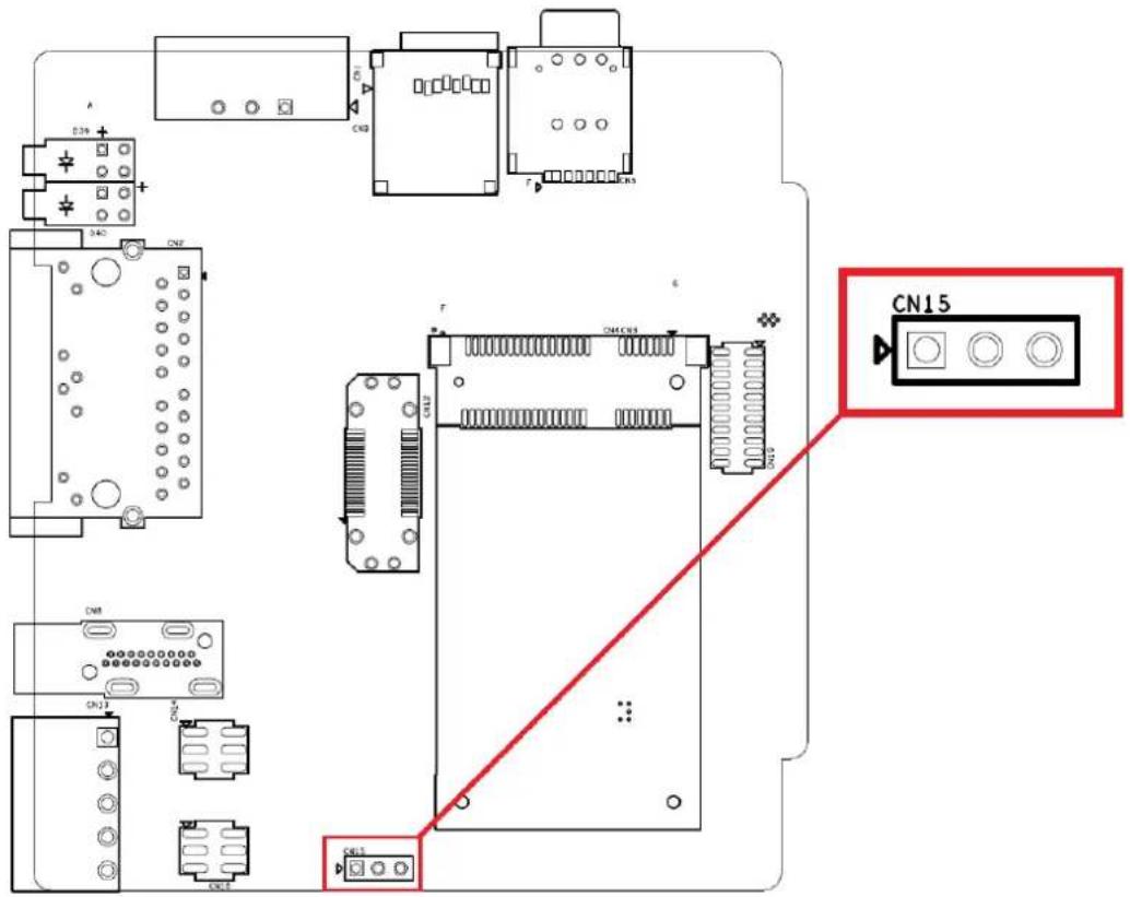
Figure 3.5 Console Port of ECU-150-12A
Table 3.5: 3-Pin COM Assignments
| Pin Assignment |
| 1 COM_Debug_TX |
| 2 COM_Debug_RX |
| 3 COM_ISO_GND |

Figure 3.6 Console Port of ECU-150-12A1
3.1.6 SD&SIM Card Installation
ECU-150 is equipped with a SD card and a Mini-PCIe interface on the front of motherboard, which supports one full-size wireless network card. If users also need a SIM card, a slot on the front of motherboard can be used. The installation is shown below.
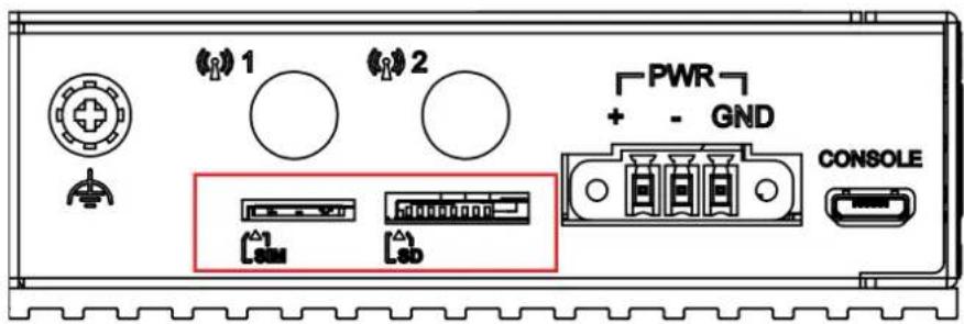
Figure 3.7 SIM & SD Card Slot
3.2 Jumper Setting
3.2.1 Jumper Setting
The motherboard of ECU-150 has two types of jumper for user operation, as shown below.
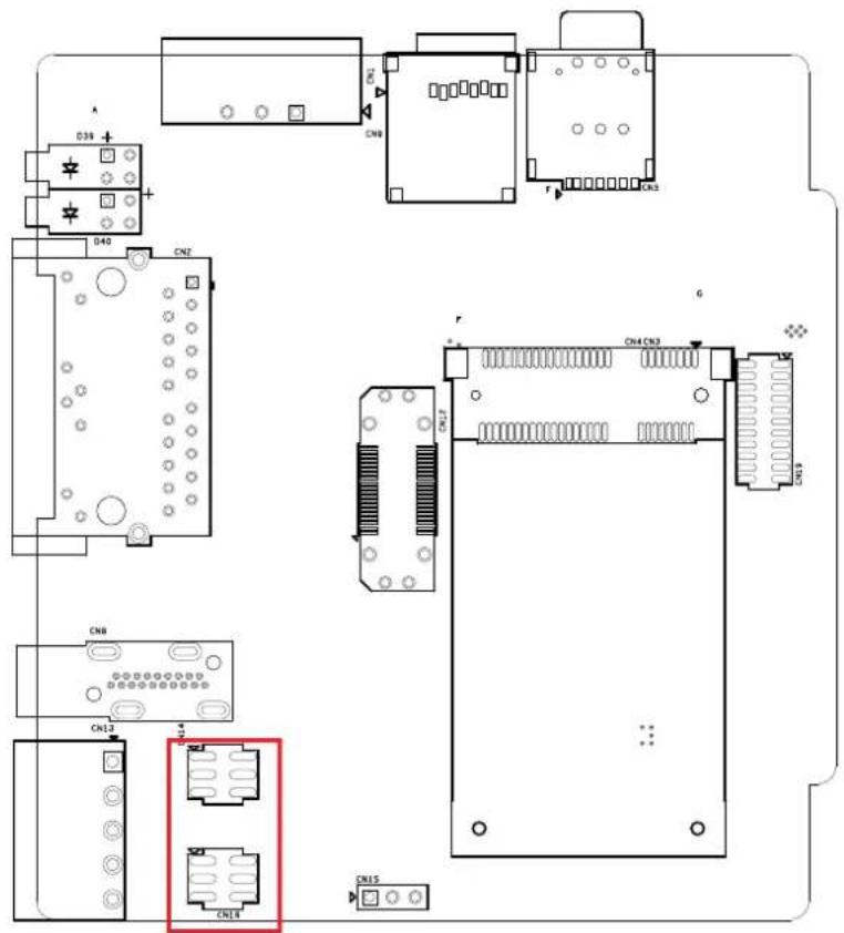
Figure 3.8 Jumper Setting
Table 3.6: Jumper Setting of Terminal Resistor For COM(1\~4)
| Location Description | ||
| CN14 (COM1) / CN16 (COM2) | 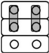 | Data+/Data- of RS-485 (Default Setting) |
| CN14 (COM1) / CN16 (COM2) |  | RX/TX of RS-232 |
3.3 Extension and Installation
3.3.1 Extension Socket and Expansion Module List
ECU-150 could be extended to a 2nd stack for extra communication by adding three types of expansion module through CN12 & CN19 sockets.
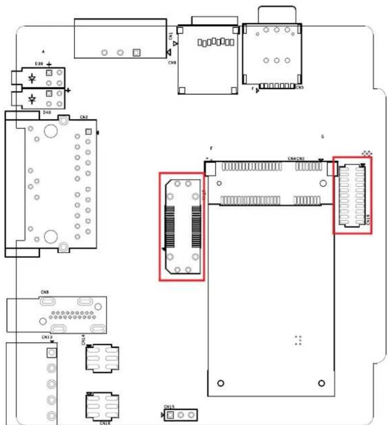
Figure 3.9 Extension Socket
Table 3.7: Expansion Modules
| Part Number Description |
| ECU-150P-M1A 2nd stack expansion module support 1 x M.2 |
| ECU-150P-D1A 2nd stack expansion module support 1 x iDOOR |
| ECU-150P-P2A 2nd stack expansion module support 2 x mPCIE |

Figure 3.10 Expansion Modules
3.3.2 Assembly of Expansion Module
Remove the top cover, assemble the expansion module onto ECU-150 aligning to the extension sockets, then fasten the four screws.
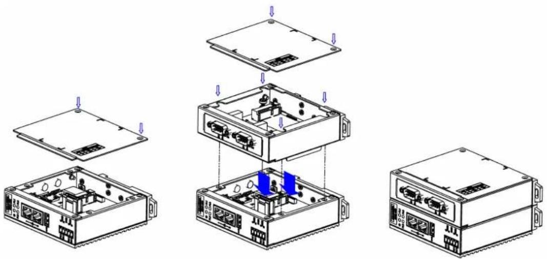
Figure 3.11 Assembly of Expansion Module
3.3.3 Wall-mounted and DIN-Rail Installation
ECU-150 supports two-in-one type of installation: Wall-mount and DIN-Rail Installation.

Figure 3.12 Wall-mount and DIN-Rail Installation
3.3.4 Installing a Wireless module Card and Antenna (Optional)
For optional wireless module card and antenna, please contact Advantech for the following wireless solution kit.
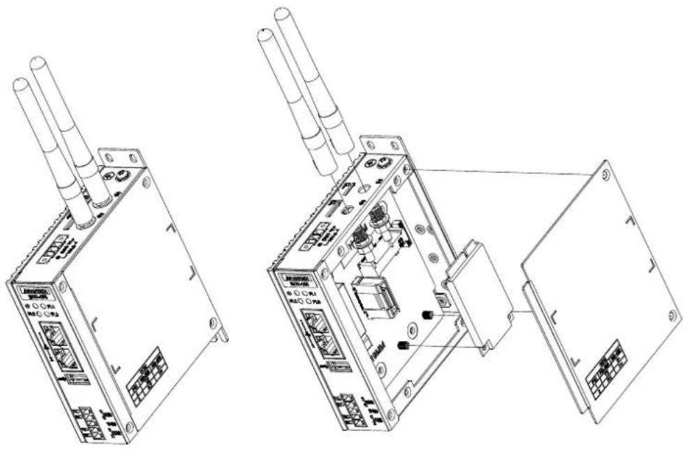
natural_image
Technical line drawings of two electronic device modules with visible ports and wiring (no text or symbols)Figure 3.13 Installing a Wireless module Card and Antenna
www.advantech.com
Please verify specifications before quoting. This guide is intended for reference purposes only.
All product specifications are subject to change without notice.
No part of this publication may be reproduced in any form or by any means, electronic, photocopying, recording or otherwise, without prior written permission of the publisher.
All brand and product names are trademarks or registered trademarks of their respective companies.
© Advantech Co., Ltd. 2024
- ECU-150 Series
- Copyright
- Acknowledgments
- Support
- Declaration of Conformity
- CE
- FCC Class A
- Technical Support and Assistance
- Safety Precaution - Static Electricity
- Safety Instructions
- Chapter 2 Hardware Functionality......7
- Chapter 3 Wiring and Installation .....11
- Chapter 1
- Introduction
- Specifications:
- General
- System
- Communication
- Environment
- SSH Login User Name & Password
- Default IP
- Software
- Protocol Support
- Safety Precautions
- Chassis Dimensions
- Packing List
- Chapter 2
- Overview
- LED Status Indicators
- System Status Indicators:
- Serial Communication Status Indicator
- LED Color Description
- Ethernet Status Indicator
- Chapter 3
- Wiring
- Power Supply Wiring
- Communication Ports
- USB Port
- LAN Port
- Console Port
- SD&SIM Card Installation
- Jumper Setting
- Jumper Setting
- Extension and Installation
- Extension Socket and Expansion Module List
- Assembly of Expansion Module
- Wall-mounted and DIN-Rail Installation
- Installing a Wireless module Card and Antenna (Optional)
- www.advantech.com
Brand : Advantech
Model : ECU-150
Category : Electronic control unit