
M18 ROVER 2368-20 - Flashlight MILWAUKEE - Free user manual and instructions
Find the device manual for free M18 ROVER 2368-20 MILWAUKEE in PDF.

| Product Type | Rechargeable LED Flashlight |
| Brand | Milwaukee |
| Model | M18 ROVER 2368-20 |
| Power Supply | M18 18 V DC battery or 120 V AC mains via adapter |
| Battery Type | M18™ |
| Charger Type | M18™ |
| Luminous Flux | 400 to 4,500 lumens |
| Protection Rating | IP54 |
| Operating Temperature | -18 °C to 40 °C |
| Main Features | Three adjustable LED panels, brightness adjustment (high, medium, low), lighting modes (center panel, outer panels, all), magnetic mounting, chevron hook, nail/screw support, AC/DC power with automatic switchover |
| Maintenance and Cleaning | Clean with a damp cloth and mild soap. Do not use harsh solvents. Keep ventilation openings free of debris. |
| Safety | Do not look directly at the light source. Remove battery when not in use. Use only recommended accessories. Follow general power tool safety instructions. |
| Spare Parts and Repairability | Repairs must be carried out by a Milwaukee authorized service center. Use only identical replacement parts. For parts, contact Milwaukee Tool or visit www.milwaukeetool.com. |
| Warranty | 5 years for the tool (except exceptions). LED is lifetime warranty. Keep proof of purchase. |
| General Information | Portable work light designed for professionals. Use on battery or mains. Supplied without battery or charger. |
Frequently Asked Questions - M18 ROVER 2368-20 MILWAUKEE
User questions about M18 ROVER 2368-20 MILWAUKEE
0 question about this device. Answer the ones you know or ask your own.
Ask a new question about this device
Download the instructions for your Flashlight in PDF format for free! Find your manual M18 ROVER 2368-20 - MILWAUKEE and take your electronic device back in hand. On this page are published all the documents necessary for the use of your device. M18 ROVER 2368-20 by MILWAUKEE.
USER MANUAL M18 ROVER 2368-20 MILWAUKEE
natural_image
Line drawing of a Milwaukee industrial machine with multiple compartments and mounting brackets (no text or symbols on the device itself)Cat. No. / No de Cat.
2368-20
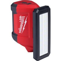
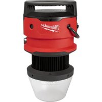
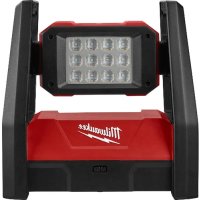
M18™ ROVER™ DUAL POWER TRIPLE-PANEL FLOOD & AREA LIGHT
LAMPE DE ZONE ET PROJECTEUR TRIPLE PANNEAUX À PUISSANCE DOUBLE M18™ ROVER™
WARNING To reduce the risk of injury, user must read and understand operator's manual.
⚠ WARNING Read all safety warnings, instructions, illustrations and specifica-
tions provided with this power tool. Failure to follow all instructions listed below may result in electric shock, fire and/or serious injury. Save all warnings and instructions for future reference. The term "power tool" in the warnings refers to your mains-operated (corded) power tool or battery-operated (cordless) power tool.
WORK AREA SAFETY
- Keep work area clean and well lit. Cluttered or dark areas invite accidents.
- Do not operate power tools in explosive atmospheres, such as in the presence of flammable liquids, gases or dust. Power tools create sparks which may ignite the dust or fumes.
- Keep children and bystanders away while operating a power tool. Distractions can cause you to lose control.
ELECTRICAL SAFETY
- Power tool plugs must match the outlet. Never modify the plug in any way. Do not use any adapter plugs with earthed (grounded) power tools. Unmodified plugs and matching outlets will reduce risk of electric shock.
- Avoid body contact with earthed or grounded surfaces, such as pipes, radiators, ranges and refrigerators. There is an increased risk of electric shock if your body is earthed or grounded.
- Do not expose power tools to rain or wet conditions. Water entering a power tool will increase the risk of electric shock.
- Do not abuse the cord. Never use the cord for carrying, pulling or unplugging the power tool. Keep cord away from heat, oil, sharp edges or moving parts. Damaged or entangled cords increase the risk of electric shock.
- When operating a power tool outdoors, use an extension cord suitable for outdoor use. Use of a cord suitable for outdoor use reduces the risk of electric shock.
- If operating a power tool in a damp location is unavoidable, use a ground fault circuit interrupter (GFCI) protected supply. Use of an GFCI reduces the risk of electric shock.
PERSONAL SAFETY
- Stay alert, watch what you are doing and use common sense when operating a power tool. Do not use a power tool while you are tired or under the influence of drugs, alcohol or medication. A moment of inattention while operating power tools may result in serious personal injury.
- Use personal protective equipment. Always wear eye protection. Protective equipment such as a dust mask, non-skid safety shoes, hard hat or hearing protection used for appropriate conditions will reduce personal injuries.
-
Prevent unintentional starting. Ensure the switch is in the off-position before connecting to power source and/or battery pack, picking up or carrying the tool. Carrying power tools with your finger on the switch or energizing power tools that have the switch on invites accidents.
-
Remove any adjusting key or wrench before turning the power tool on. A wrench or a key left attached to a rotating part of the power tool may result in personal injury.
- Do not overreach. Keep proper footing and balance at all times. This enables better control of the power tool in unexpected situations.
- Dress properly. Do not wear loose clothing or jewelry. Keep your hair and clothing away from moving parts. Loose clothes, jewelry or long hair can be caught in moving parts.
- If devices are provided for the connection of dust extraction and collection facilities, ensure these are connected and properly used. Use of dust collection can reduce dust-related hazards.
- Do not let familiarity gained from frequent use of tools allow you to become complacent and ignore tool safety principles. A careless action can cause severe injury within a fraction of a second.
POWER TOOL USE AND CARE
- Do not force the power tool. Use the correct power tool for your application. The correct power tool will do the job better and safer at the rate for which it was designed.
- Do not use the power tool if the switch does not turn it on and off. Any power tool that cannot be controlled with the switch is dangerous and must be repaired.
- Disconnect the plug from the power source and/or remove the battery pack, if detachable, from the power tool before making any adjustments, changing accessories, or storing power tools. Such preventive safety measures reduce the risk of starting the power tool accidentally.
- Store idle power tools out of the reach of children and do not allow persons unfamiliar with the power tool or these instructions to operate the power tool. Power tools are dangerous in the hands of untrained users.
- Maintain power tools and accessories. Check for misalignment or binding of moving parts, breakage of parts and any other condition that may affect the power tool's operation. If damaged, have the power tool repaired before use. Many accidents are caused by poorly maintained power tools.
- Keep cutting tools sharp and clean. Properly maintained cutting tools with sharp cutting edges are less likely to bind and are easier to control.
- Use the power tool, accessories and tool bits etc. in accordance with these instructions, taking into account the working conditions and the work to be performed. Use of the power tool for operations different from those intended could result in a hazardous situation.
- Keep handles and grasping surfaces dry, clean and free from oil and grease. Slippery handles and grasping surfaces do not allow for safe handling and control of the tool in unexpected situations.
BATTERY TOOL USE AND CARE
- Recharge only with the charger specified by the manufacturer. A charger that is suitable for one type of battery pack may create a risk of fire when used with another battery pack.
-
Use power tools only with specifically designated battery packs. Use of any other battery packs may create a risk of injury and fire.
-
When battery pack is not in use, keep it away from other metal objects, like paper clips, coins, keys, nails, screws or other small metal objects, that can make a connection from one terminal to another. Shorting the battery terminals together may cause burns or a fire.
- Under abusive conditions, liquid may be ejected from the battery; avoid contact. If contact accidentally occurs, flush with water. If liquid contacts eyes, additionally seek medical help. Liquid ejected from the battery may cause irritation or burns.
- Do not use a battery pack or tool that is damaged or modified. Damaged or modified batteries may exhibit unpredictable behavior resulting in fire, explosion or risk of injury.
- Do not expose a battery pack or tool to fire or excessive temperature. Exposure to fire or temperature above 265^ (130°C) may cause explosion.
- Follow all charging instructions and do not charge the battery pack or tool outside the temperature range specified in the instructions. Charging improperly or at temperatures outside the specified range may damage the battery and increase the risk of fire.
SERVICE
- Have your power tool serviced by a qualified repair person using only identical replacement parts. This will ensure that the safety of the power tool is maintained.
- Never service damaged battery packs. Service of battery packs should only be performed by the manufacturer or authorized service providers.
SPECIFIC SAFETY RULES FOR LIGHTS
- WARNING To reduce the risk of injury, do not look directly into the light when the flood light is on.
- Make sure that the object the light will be mounted on is free from dirt, oils, or other debris that may prevent the light from attaching securely.
• Make sure that all magnets make contact with the magnetic surface. - Make sure that the magnetic surface is free from materials that could prevent the magnets from attaching.
• Always use common sense and be cautious when using tools. It is not possible to anticipate every situation that could result in a dangerous outcome. Do not use this tool if you do not understand these operating instructions or you feel the work is beyond your capability; contact Milwaukee Tool or a trained professional for additional information or training. - Maintain labels and nameplates. These carry important information. If unreadable or missing, contact a MILWAUKEE service facility for a replacement.
EXTENSION CORDS
Grounded tools require a three wire extension cord. Double insulated tools can use either a two or three wire extension cord. As the distance from the supply outlet increases, you must use a heavier gauge extension cord. Using extension cords with inadequately sized wire causes a serious drop in voltage, resulting in loss of power and possible tool damage. Refer to the table shown to determine the required minimum wire size.
The smaller the gauge number of the wire, the greater the capacity of the cord. For example, a 14 gauge cord can carry a higher current than a 16 gauge cord. When using more than one extension cord to make up the total length, be sure each cord contains at least the minimum wire size required. If you are using one extension cord for more than one tool, add the nameplate amperes and use the sum to determine the required minimum wire size.
Guidelines for Using Extension Cords
- If you are using an extension cord outdoors, be sure it is marked with the suffix "W" to indicate that it is acceptable for outdoor use.
- Be sure your extension cord is properly wired and in good electrical condition. Always replace a damaged extension cord or have it repaired by a qualified person before using it.
- Protect your extension cords from sharp objects, excessive heat and damp or wet areas.
- When stringing lights together, consider the total Amperes draw when selecting the extension cords.
| Recommended Minimum Wire Gauge For Extension Cords* | |||||
| Nameplate Amps | Extension Cord Length | ||||
| 25' 50' 75' | 100' 150' | ||||
| 0 - 2.0 | 18 | 18 | 18 | 18 | 16 |
| 2.1 - 3.4 | 18 | 18 | 18 | 16 | 14 |
| 3.5 - 5.0 | 18 | 18 | 16 | 14 | 12 |
| 5.1 - 7.0 | 18 | 16 | 14 | 12 | 12 |
| 7.1 - 12.0 | 16 | 14 | 12 | 10 | -- |
| 12.1 - 16.0 | 14 | 12 | 10 | -- | -- |
| 16.1 - 20.0 | 12 | 10 | -- | -- | -- |
* Based on limiting the line voltage drop to five volts at 150% of the rated amperes.
READ AND SAVE ALL INSTRUCTIONS FOR FUTURE USE.
SPECIFICATIONS
Cat. No....2368-20
Volts....18 DC
Battery Type......M18™
Charger Type.....M18™
AC Input Volts....120 V
AC Input Amps 0.5 A
DC Input Volts 18 V
DC Input Amps 2 A
Lumen Output Range 400 - 4500 lm
Ingress Protection....IP54
Recommended Ambient
Operating Temperature.... 0°F to 104°F
NOTE: The light is isolated from the AC receptacle ground pin.
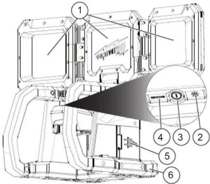
FUNCTIONAL DESCRIPTION
-
LED panels
-
Brightness button
-
Power button
-
Mode button
-
AC power door
-
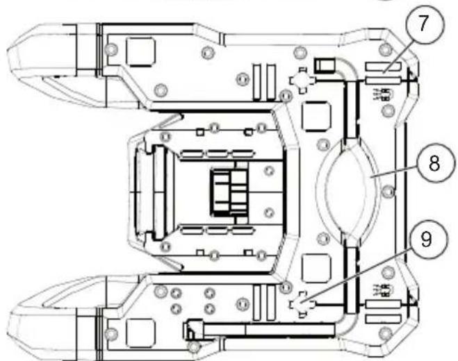
Handles (2)
-
Magnets
-
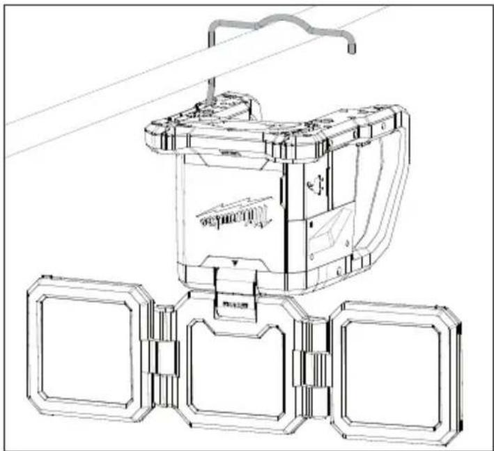
Rafter hook
-
Hang holes
SYMBOLOGY


Direct Current

Alternating Current

Amps


Risk of Electric Shock


Do not stare at the source


Surface is hot.
ntact.

Read Operator's Manual

Magnets

DC Power
AC Power

Approval Mark for Mexico

UL Listing for Canada and U.S.
ASSEMBLY
AWARNING Recharge only with the charger specified for the battery. For specific charging instructions, read the operator's manual supplied with the charger and battery.
Removing/Inserting the Battery
To remove the battery, push in the release buttons and pull the battery pack away from the tool.
⚠ WARNING Remove the battery pack any time the tool is not in use.
To insert the battery, slide the pack into the body of the tool. Make sure it latches securely into place.
AWARNING Only use accessories specifically recommended for this tool. Others may be hazardous.
Operating the Light On AC/DC Power
Insert a battery pack to run on DC power. Plug an extension cord into the AC outlet to run on AC power. If both battery and extension cord are inserted, AC power will be used, with DC power as a backup.
NOTE: This tool does not charge battery packs.
OPERATION
AWARNING To reduce the risk of injury, do not look directly into the light when the light is on, causing vision damage.
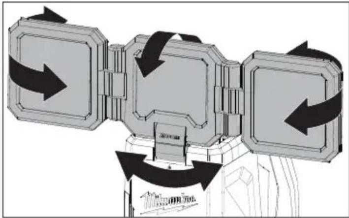
Adjusting the LED Panels
This tool has three different LED panels that can be adjusted. Adjust the tool before powering on.
- The two outer panels can hinge in the left or right directions.
- The middle hinge controls the up and down motion, and horizontal or vertical positions.
flowchart
graph TD
    A["Start"] --> B{Step 1}
    B --> C["Step 2"]
    C --> D["Step 3"]
    D --> E["End"]
Turning the Light On/Off
- To turn on the light, press the power button once.
• To turn off the light, press the power button again.
NOTE: Ensure the light is turned off before storing.
Mode and Brightness Buttons
This light has a mode button and brightness button. The mode button controls how many LED panels are active. The brightness button controls the high, medium, and low setting of the LED in the panels.
- Press the mode button to toggle through the different light settings of: middle panel, outer panels, and all panels active.
- Press the brightness button to toggle through: high, medium, and low brightness levels.
AWARNING Ensure the hanging surface is sturdy and the rafter hook is secure before using. A falling light could strike people or objects below.
To reduce the risk of injury or damage to the tool, ensure the nail can support the weight of the tool. To reduce the risk of injury or damage to the tool, ensure that all magnets make contact with magnetic surface.
Ensure the magnetic surface is clear from dirt and debris that could prevent the magnets from attaching.
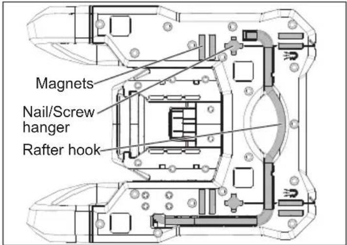
Mounting Options
The light can be mounted several ways:
• Using the rafter hook.
- Using the nail/screw hanger with groove located on the back of the light.
- Using the magnets to attach to a metal surface. The magnets are designed to attach to a uncoated ferrous surface that is at least 0.06" (16GA) thick.
natural_image
Technical line drawing of a mechanical device with three circular components and a curved top component (no text or symbols)MAINTENANCE
WARNING
To reduce the risk of injury, always unplug the charger and remove the
battery pack from the charger or tool before performing any maintenance. Never disassemble the battery pack, charger, or tool, except as provided in these instructions. Contact a MILWAUKEE service facility for all other repairs.
Maintaining Tool
Keep the tool, battery pack and charger in good repair by adopting a regular maintenance program. Inspect the tool for issues such as undue noise, misalignment or binding of moving parts, breakage of parts, or any other condition that may affect the tool operation. Return the tool, battery pack, and charger to a MILWAUKEE service facility for repair. After six months to one year, depending on use, return the tool, battery pack and charger to a MILWAUKEE service facility for inspection.
If the tool does not start or operate at full power with a fully charged battery pack, clean the contacts on the battery pack. If the tool still does not work properly, return the tool, charger and battery pack, to a MILWAUKEE service facility for repairs.
WARNING
To reduce the risk of personal in-jury and damage, never immerse tool, battery pack or charger in liquid or allow a liquid to flow inside them.
Cleaning
Clean dust and debris from any vents. Keep tool clean, dry and free of oil or grease. Use only mild soap and a damp cloth to clean, since certain cleaning agents and solvents are harmful to plastics and other insulated parts. Some of these include gasoline, turpentine, lacquer thinner, paint thinner, chlorinated cleaning solvents, ammonia and household detergents containing ammonia. Never use flammable or combustible solvents around tools.
Repairs
For repairs, return the tool, battery pack and charger to the nearest authorized service center.
ACCESSORIES
WARNING
Use only recommended accessories. Others may be hazardous.
For a complete listing of accessories, go online to www.milwaukeeetool.com or contact a distributor.
SERVICE - UNITED STATES
1-800-SAWDUST (1.800.729.3878)
Monday-Friday, 7:00 AM - 6:30 PM CST
or visit www.milwaukeetool.com
Contact Corporate After Sales Service Technical Support with technical, service/repair, or warranty questions.
Email: metproductsupport@milwaukeeetool.com
Become a Heavy Duty Club Member at www.milwaukeeetool.com to receive important notifications regarding tool purchases.
SERVICE - CANADA
Milwaukee Tool (Canada) Ltd 1.877.948.2360
Monday-Friday, 7:00 AM - 4:30 PM CST
or visit www.milwaukeetool.ca
LIMITED WARRANTY USA & CANADA
This MILWAUKEE power tool* is warranted to the original purchaser from an authorized MILWAUKEE distributor only to be free from defects in material and workmanship. Subject to certain exceptions, MILWAUKEE will repair or replace any part on this power tool which, after examination, is determined by MILWAUKEE to be defective in material or workmanship for a period of five (5) years after the date of purchase unless otherwise noted. Return of the power tool to a MILWAUKEE factory Service Center location or MILWAUKEE Authorized Service Station, freight prepaid and insured, is required. A copy of the proof of purchase should be included with the return product. This warranty does not apply to damage that MILWAUKEE determines to be from repairs made or attempted by anyone other than MILWAUKEE authorized personnel, misuse, alterations, abuse, normal wear and tear, lack of maintenance, or accidents.
Normal Wear: Many power tools need periodic parts replacement and service to achieve best performance. This warranty does not cover repair when normal use has exhausted the life of a part including, but not limited to, carriage gears, chucks, brushes, cords, saw shoes, blade clamps, o-rings, seals, bumpers, driver blades, pistons, strikers, lifters, and bumper cover washers.
*This warranty does not cover battery packs or all power tools. Refer to the separate and distinct warranties available for those products. The warranty period for the LED in the LED Work Light (49-24-0171) and the LED Upgrade Bulb (49-81-0090) is the lifetime of the product subject to the limitations above. If during normal use the LED or LED Upgrade Bulb fails, the part will be replaced free of charge.
Warranty Registration is not necessary to obtain the applicable warranty on a MILWAUKEE power tool product. The manufacturing date of the product will be used to determine the warranty period if no proof of purchase is provided at the time warranty service is requested. ACCEPTANCE OF THE EXCLUSIVE REPAIR AND REPLACEMENT REMEDIES DESCRIBED HEREIN IS A CONDITION OF THE CONTRACT FOR THE PURCHASE OF EVERY MILWAUKEE PRODUCT. IF YOU DO NOT AGREE TO THIS CONDITION, YOU SHOULD NOT PURCHASE THE PRODUCT. IN NO EVENT SHALL MILWAUKEE BE LIABLE FOR ANY INCIDENTAL, SPECIAL, CONSEQUENTIAL, OR PUNITIVE DAMAGES, OR FOR ANY COSTS, ATTORNEY FEES, EXPENSES, LOSSES OR DELAYS ALLEGED TO BE AS A CONSEQUENCE OF ANY DAMAGE TO, FAILURE OF, OR DEFECT IN ANY PRODUCT INCLUDING, BUT NOT LIMITED TO, ANY CLAIMS FOR LOSS OF PROFITS. SOME STATES DO NOT ALLOW THE EXCLUSION OR LIMITATION OF INCIDENTAL OR CONSEQUENTIAL DAMAGES, SO THE ABOVE LIMITATION OR EXCLUSION MAY NOT APPLY TO YOU. THIS WARRANTY IS EXCLUSIVE AND IN LIEU OF ALL OTHER EXPRESS WARRANTIES, WRITTEN OR ORAL. TO THE EXTENT PERMITTED BY LAW, MILWAUKEE DISCLAIMS ANY IMPLIED WARRANTIES, INCLUDING WITHOUT LIMITATION ANY IMPLIED WARRANTY OF MERCHANTABILITY OR FITNESS FOR A PARTICULAR USE OR PURPOSE; TO THE EXTENT SUCH DISCLAIMER IS NOT PERMITTED BY LAW, SUCH IMPLIED WARRANTIES ARE LIMITED TO THE DURATION OF THE APPLICABLE EXPRESS WARRANTY AS DESCRIBED ABOVE. SOME STATES DO NOT ALLOW LIMITATIONS ON HOW LONG AN IMPLIED WARRANTY LASTS, SO THE ABOVE LIMITATION MAY NOT APPLY TO YOU, THIS WARRANTY GIVES YOU SPECIFIC LEGAL RIGHTS, AND YOU MAY ALSO HAVE OTHER RIGHTS WHICH VARY FROM STATE TO STATE.
This warranty applies to product sold in the U.S.A. and Canada only. Please consult the 'Service Center Search' in the Parts & Service section of MILWAUKEE's website www.milwaukeetool.com or call 1.800.SAWDUST (1.800.729.3878) to locate your nearest service facility for warranty and non-warranty service on a MILWAUKEE power tool.
RÈGLES DE SÉCURITÉ GÉNÉRALES RELATIVES AUX OUTILS ÉLECTRIQUES
AVERTISSEMENT
natural_image
Technical line drawing of a mechanical device with three circular components and a curved top component (no text or symbols)ENTRETIEN
Milwaukee Tool (Canada) Ltd 1.877.948.2360
Monday-Friday, 7:00 AM - 4:30 PM CST
www.milwaukeetool.ca
GARANTIE LIMITÉE- AUX ÉTATS-UNIS ET AU CANADA
natural_image
Technical line drawing of a mechanical device with multiple circular components and a curved top component (no text or symbols)MANTENIMIENTO
Lunes a Viernes (9am a 6pm)

- M18™ ROVER™ DUAL POWER TRIPLE-PANEL FLOOD & AREA LIGHT
- LAMPE DE ZONE ET PROJECTEUR TRIPLE PANNEAUX À PUISSANCE DOUBLE M18™ ROVER™
- ⚠ WARNING Read all safety warnings, instructions, illustrations and specifica-
- WORK AREA SAFETY
- ELECTRICAL SAFETY
- PERSONAL SAFETY
- POWER TOOL USE AND CARE
- BATTERY TOOL USE AND CARE
- SERVICE
- SPECIFIC SAFETY RULES FOR LIGHTS
- EXTENSION CORDS
- Guidelines for Using Extension Cords
- READ AND SAVE ALL INSTRUCTIONS FOR FUTURE USE.
- SPECIFICATIONS
- FUNCTIONAL DESCRIPTION
- SYMBOLOGY
- ASSEMBLY
- OPERATION
- AWARNING To reduce the risk of injury, do not look directly into the light when the light is on, causing vision damage.
- Adjusting the LED Panels
- Turning the Light On/Off
- Mode and Brightness Buttons
- AWARNING Ensure the hanging surface is sturdy and the rafter hook is secure before using. A falling light could strike people or objects below.
- Mounting Options
- MAINTENANCE
- WARNING
- Maintaining Tool
- Cleaning
- Repairs
- ACCESSORIES
- SERVICE - UNITED STATES
- SERVICE - CANADA
- Milwaukee Tool (Canada) Ltd 1.877.948.2360
- LIMITED WARRANTY USA & CANADA
- RÈGLES DE SÉCURITÉ GÉNÉRALES RELATIVES AUX OUTILS ÉLECTRIQUES
- AVERTISSEMENT
- GARANTIE LIMITÉE- AUX ÉTATS-UNIS ET AU CANADA
- MANTENIMIENTO
Brand : MILWAUKEE
Model : M18 ROVER 2368-20
Category : Flashlight