
UNC15NPWII - Ice machine Café - Free user manual and instructions
Find the device manual for free UNC15NPWII Café in PDF.

| Product Type | Under-counter Ice Maker |
| Brand | Café (GE Appliances) |
| Model | UNC15NPWII |
| Dimensions (H x W x D) | Adjustable height 34 to 35 in (86.4 to 88.9 cm), Width 15 in (38.1 cm), Depth 24 in (61 cm) (excluding handle and fittings) |
| Weight | Approximately 80 lb (36 kg) |
| Power Supply | 120 V, 60 Hz, 15 A, dedicated circuit with grounding |
| Ice Storage Capacity | 9 kg (20 lb) |
| Ice Production | Approximately 6 to 7 hours to fill the bin (depends on conditions) |
| Ice Type | Cubed ice |
| Water Connection | Potable water, pressure 30 to 120 psi (275 to 827 kPa), temperature 40 to 90 °F (4.5 to 32 °C) |
| Drainage | Gravity drain or drain pump (UPK4 kit optional) |
| Main Functions | Power On/Off, Clean, Filter Reset, Wi-Fi (SmartHQ), Door Alarm, Sabbath Mode, Indicators: Making Ice, Time to Clean, Replace Filter |
| Water Filtration | GSWF cartridge filter (replacement every 6 months approximately) |
| Refrigerant | Isobutane (R600a), flammable |
| Warranty | 1 year parts and labor, 5 years sealed system (compressor, condenser, evaporator) |
| Spare Parts and Accessories | Door panels (ZK1UN150RSS, PK1UG150RSS, CK1UP150RS1, etc.), handles (CXQW1H1PPSS, etc.), pump kit UPK4, filter GSWF, cleaner WX01X40745 |
| Maintenance and Cleaning | Condenser cleaning, descaling with specific product (WX01X40745), exterior cleaning with mild stainless steel cleaner |
| Safety | Plug into grounded outlet, do not use extension cord, remove door before disposal, keep children away |
| Repairability | Repairs by qualified professional, parts available via GE Appliance Parts |
| General Information | For indoor use, ambient temperature 55 to 100 °F (13 to 38 °C), best performance between 60 and 80 °F (16 to 27 °C) |
Frequently Asked Questions - UNC15NPWII Café
User questions about UNC15NPWII Café
0 question about this device. Answer the ones you know or ask your own.
Ask a new question about this device
Download the instructions for your Ice machine in PDF format for free! Find your manual UNC15NPWII - Café and take your electronic device back in hand. On this page are published all the documents necessary for the use of your device. UNC15NPWII by Café.
USER MANUAL UNC15NPWII Café
SAFETY INFORMATION .... 3
USING THE ICE MACHINE
Packaging 6
Controls 6
Features 8
Starting the Ice Machine 8
INSTALLATION INSTRUCTIONS
Grounding the Ice Machine ..... 9
Before You Begin 9
Location and Preparation 9
Advance Planning 11
Dimensions 12
Door Swing 13
Door Panel 15
Handle Reversing Instructions .....18
Plumbing 18
Toe Kick Location 19
Drain Pump Kit UPK4 Accessory
Installation 20
CARE AND CLEANING....24
TROUBLESHOOTING TIPS ..... 27
LIMITED WARRANTY....28
ACCESSORIES 29
CONSUMER SUPPORT .... 32
Write the model and serial numbers here:
Model # ____
Serial # ____
Find these numbers on a label on the top inner case liner of the unit toward the front.
OWNER'S MANUAL AND INSTALLATION INSTRUCTIONS
UNC15NP
ENGLISH/FRANÇAIS/ ESPAÑOL
THANK YOU FOR MAKING GE APPLIANCES A PART OF YOUR HOME.
Whether you grew up with GE Appliances, or this is your first, we're happy to have you in the family.
We take pride in the craftsmanship, innovation and design that goes into every GE Appliances product, and we think you will too. Among other things, registration of your appliance ensures that we can deliver important product information and warranty details when you need them.
Register your GE appliance now online. Helpful websites and phone numbers are available in the Consumer Support section of this Owner's Manual. You may also mail in the pre-printed registration card included in the packing material.

GE APPLIANCES
IMPORTANT SAFETY INFORMATION READ ALL INSTRUCTIONS BEFORE USING THE APPLIANCE
WARNING
To reduce the risk of fire, explosion, electric shock, or injury when using your ice machine, follow these basic safety precautions:
This Ice machine must be properly installed and located in accordance with the Installation Instructions before it is used.
■ Unplug the Ice machine before making repairs, replacing a light bulb, or cleaning.
NOTE: Power to the Ice machine cannot be disconnected by any setting on the control panel.
NOTE: Repairs must be performed by a qualified Service Professional.
■ Replace all parts and panels before operating.
■ Do not use an extension cord.
■ Do not store or use gasoline or other flammable vapors and liquids in the vicinity of this or any other appliance.
■ Do not store explosive substances such as aerosol cans with a flammable propellant in this appliance.
■ To prevent suffocation and entrapment hazards to children, remove the Ice machine door from any Ice machine before disposing of it or discontinuing its use.
■ To avoid serious injury or death, children should not stand on, or play in or with the appliance.
■ Children and persons with reduced physical, sensory or mental capabilities or lack of experience and knowledge can use this appliance only if they are supervised or have been given instructions on safe use and understand the hazards involved.
This appliance is intended to be used in household and similar applications such as: staff kitchen areas in shops, offices and other working environments; farm houses; by clients in hotels, motels, bed & breakfast and other residential environments; catering and similar non-retail applications.
■ Connect to potable water supply only. A cold water supply is required for automatic icemaker operation. The water pressure must be between 30 and 120 psi (275-827 kilopascals).
- Do not apply harsh cleaners to the Ice machine. Certain cleaners will damage plastic which may cause parts such as the door or door handles to detach unexpectedly. See the Care and Cleaning section for detailed instructions.
CAUTION
To reduce the risk of injury when using your Ice machine, follow these basic safety precautions.
- Keep fingers out of the “pinch point” areas; clearances between the doors and between the doors and cabinet are necessarily small. Be careful closing doors when children are in the area.
■ Do not touch the cold surfaces in the ice compartment.
■ Avoid contact with moving parts of the ejector mechanism of the icemaker.
INSTALLATION
WARNING

XPLOSION HAZARD
Keep flammable materials and vapors, such as gasoline, away from appliance. Failure to do so can result in fire, explosion, or death.
READ AND SAVE THESE INSTRUCTIONS
IMPORTANT SAFETY INFORMATION READ ALL INSTRUCTIONS BEFORE USING THE APPLIANCE
▲WARNING

RE OR EXPLOSION HAZARD
Flammable Refrigerant
This appliance contains isobutane refrigerant, also known as R600a, a natural gas with high environmental compatibility. However, it is also combustible. Adhere to the warnings below to reduce the risk of injury or property damage.
- When handling, installing and operating the appliance, care should be taken to avoid damage to the refrigerant tubing.
- Service shall only be performed by authorized service personnel. Use only manufacturer-authorized service parts.
-
Dispose of Ice machine in accordance with Federal and Local Regulations. Flammable refrigerant and insulation material used require special disposal procedures. Contact your local authorities for the environmentally safe disposal of your Ice machine.
-
Keep ventilation openings in the appliance enclosures or in the built-in structure clear of obstruction.
- Do not use an ice pick, metal or sharp edged instrument to remove any frost or ice in the ice maker compartment as it may puncture the liner and then the flammable refrigerant tubing behind it.
- Do not use electrical appliances inside the food storage compartment of the appliance.
- Do not use any electrical device for melting or thawing any ice or frost in your icemaker.
CONNECTING ELECTRICITY
WARNING

.ECTRICAL SHOCK HAZARD
Plug into a grounded 3-prong outlet
Do not remove the ground prong
Do not use an adapter
Failure to follow these instructions can result in death, fire, or electrical shock.
Do not, under any circumstances, cut or remove the third (ground) prong from the power cord. For personal safety, this appliance must be properly grounded.
The power cord of this appliance is equipped with a 3-prong (grounding) plug which mates with a standard 3-prong (grounding) wall outlet to minimize the possibility of electric shock hazard from this appliance.
Have the wall outlet and circuit checked by a qualified electrician to make sure the outlet is properly grounded.
Where a standard 2-prong wall outlet is encountered, it is your personal responsibility and obligation to have it replaced with a properly grounded 3-prong wall outlet.
The ice maker should always be plugged into its own 120 volt, 60 Hz, 15 amp circuit. This provides the best
performance and also prevents overloading house wiring circuits which could cause a fire hazard from overheated wires.
Never unplug your ice maker by pulling on the power cord. Always grip plug firmly and pull straight out from the outlet.
Repair or replace immediately all power cords that have become frayed or otherwise damaged. Do not use a cord that shows cracks or abrasion damage along its length or at either end.
When moving the ice maker, be careful not to roll over or damage the power cord.
READ AND SAVE THESE INSTRUCTIONS
IMPORTANT SAFETY INFORMATION READ ALL INSTRUCTIONS BEFORE USING THE APPLIANCE
PROPER DISPOSAL OF YOUR OLD APPLIANCE
WARNING
SUFFOCATION AND CHILD ENTRAPMENT HAZARD
Remove the door from the appliance prior to disposal. Failure to do so can result in child entrapment which can lead to death or brain damage.
IMPORTANT: Child entrapment and suffocation are not problems of the past. Junked or abandoned appliances are still dangerous even if they will sit for "just a few days." If you are getting rid of your old appliance, please follow the instructions below to help prevent accidents.
Before You Throw Away Your Old Appliance:
■ Take off the doors.
■ Leave the internal components in place so that children may not easily climb inside.
REFRIGERANT AND FOAM DISPOSAL:
Dispose of or recycle appliance in accordance with Federal and Local Regulations. Flammable refrigerant and insulation material used requires special disposal procedures. Contact your local authorities for the environmentally safe disposal or recycling of your appliance.
READ AND SAVE THESE INSTRUCTIONS
Packaging
Remove Packaging
IMPORTANT: Do not remove any permanent instruction labels inside your ice machine or the Tech Sheet that is fastened behind the kickplate.
■ Remove tape and any labels from your ice maker before using (except the model and serial number label).
To remove any remaining tape or glue, rub the area briskly with your thumb. Tape or glue residue can also be easily removed by rubbing a small amount of liquid dish soap over the adhesive with your fingers. Wipe with warm water and dry.
■ Do not use sharp instruments, rubbing alcohol, flammable fluids or abrasive cleaners to remove tape or glue. These products can damage the surface of your ice maker. For more information, see Important Safety Instructions.
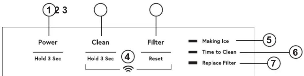
Controls
flowchart
graph TD
    A["Power"] --> B["Hold 3 Sec"]
    C["Clean"] --> D["Hold 3 Sec"]
    E["Filter"] --> F["Reset"]
    G["Making Ice"] --> H["5"]
    I["Time to Clean"] --> J["6"]
    K["Replace Filter"] --> L["7"]
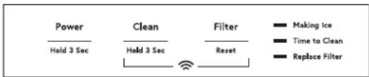
- POWER - Press and hold for 3 seconds to turn icemaking on. Making Ice Indicator will turn on. Press and hold for 3 seconds to turn icemaking off. (If icemaker is making ice when turned off, the Making Ice indicator will flash for 1 to 3 minutes to allow the icemaker to complete the icemaking process prior to turning off. The icemaker will also drain any water in the tank every time it is turned off.) If during icemaking, you need to turn off your product immediately, press and hold the "Power" button for 3 seconds again.
- CLEAN - Press and hold for 3 seconds to start the cleaning process. (See Care and Cleaning)
- FILTER RESET - Press after changing filter to reset filter timer. (See GSWF Water Filter)
- WiFi - Press and hold Clean and Filter buttons at the same time. WiFi symbol will start blinking. (See Wifi section)
- MAKING ICE - Indicator will be on when unit is with in icemaking mode.
- TIME TO CLEAN - Indicator will turn on after 5 months indicating it is time to order cleaner. Indicator will flash after 6 months indicating it is time to clean the machine. (See Care and Cleaning)
- Replace Filter - Indicator will illuminate when it is time to order a filter. Indicator will flash when it is time to replace the filter. (See GSWF Water Filter)
Sabbath Mode
The Sabbath Mode was designed for use on the Jewish Sabbath and Holidays. The icemaker will not make ice during the Sabbath mode. If Sabbath mode is entered while making ice, icemaking will continue for one to two minutes to clear out any ice that is currently in the system. Icemaking will start again at the end of the Sabbath mode. If the icemaker is equipped with a drain pump, it will continue to work as normal.
The icemaker will exit Sabbath mode automatically after 96 hours.
ON/OFF - To activate the Sabbath Mode, Press and hold "Power" and "Filter Reset" for 3 seconds. To exit Sabbath Mode, Press and Hold "Power" and "Filter Reset" for 3 seconds. The "Making Ice", "Time to Clean", and "Replace Filter" lights will all turn on to indicate Sabbath mode is active"
Door Alarm
An alert will sound when the door has been left open for 2 minutes. The alert stops when door is closed. Snooze the alert by pressing any button.
Disable the door alarm by pressing "Power", "Clean" and "Filter Reset" buttons at the same time. To Re-activate Door Alarm, press "Power", "Clean" and "Filter Reset" buttons at the same time.
Appliance Communication
WiFi (for customers in the United States, its territories, and Canada)
■ Download the SmartHQ app.
• Available for iPhone from the Apple Store or from link at GEAppliances.com.
• Available for Android from Google Play or from link at GEAppliances.com.
■ Select Create Account on app.
- Enter information, and select Register. An e-mail will be generated.
- When you receive the e-mail, select Verify Account.
• Sign in with your credentials and select the app to communicate with your icemaker.
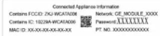
■ Find the "Connected Appliance Information" label the Water Filter Access Door at the bottom of Identify the label to select the right connecting
Icemakers Models with Password Label:
■ Set up the app.
- Press the ⊖ at the top of the screen.
- Choose GE Appliances>Refrigeration>Under Icemaker>
- The info button will show a picture of the touch display on the appliance. Select OK.
- Select Next.
■ Press WiFi Connect on the control. Press and hold Clean and Filter buttons at the same time The WiFi symbol will start flashing on the display.
- Select Next in the app.
■ Find the password on the "Connected Appliance Information" Label.
- Enter the password into the app.
■ Connect to the Icemaker's WiFi Module in the phone's WiFi settings, then return back to the SmartHQ App and select Next.
- The WiFi will have the format "GE_MODULE_XXX". module number can also be found on the label.
- Connect to the home WiFi network and type in the home WiFi password.
Icemakers Models with UPD ID Label:
| Authorized to allowby opening | Connected Appliance Information | |
| Contains FCCID: ZKJ-WCATA008 | UPD ID:XX-XX-XX-XX-XX-XX | |
| Contains IC: 10228A-WCATA008 | ||
| MAC ID: XX-XX-XX-XX-XX-XX | PT NO.XXXXXXXXXX | |
the ■ Ice Maker Press WiFi Connect on the control. Press and hold Clean method and Filter buttons at the same time. The WiFi symbol will start flashing on the display.
■ Set up the app.
- Press the ⊕ at the top of the screen.
- Icemaker will scan nearby automatically. If the mobile p Bule-Tooth off, click "GO TO SETTING" to turn it on firstly. Press Scan in app after that again.
- Select "Under Counter Ice Maker" for connecting. - App will search for available WiFi Networks automatically.
- Select the home WiFi network and type in the home WiFi password.
If all check marks appear and the user gets a that says the device is connected, the device has been successfully connected.
If the app fails to connect, the app will display Something Went Wrong" screen. The user will be possible reasons why connection failed and the option to retry.
screen the given
Regulatory Information
FCC/IC Compliance Statement:
This device complies with Part 15 of the FCC Rules. Operation is subject to the following two conditions:
- This device may not cause harmful interference, and
- This device must accept any interference received, including interference that may cause undesired operation.
This equipment has been tested and found to comply with the limits for a Class B digital device, pursuant to Part 15 of the FCC Rules. These limits are designed to provide reasonable protection against harmful interference in a residential installation. This equipment generates, uses and can radiate radio frequency energy and, if not installed and used in accordance with the instructions, may cause harmful interference to radio communications.
However, there is no guarantee that interference will not occur in a particular installation. If this equipment does cause harmful
interference to radio or television reception, which can be determined by turning the equipment off and on, the user is encouraged to try to correct the interference by one or more of the following measures:
- Reorient or relocate the receiving antenna.
- Increase the separation between the equipment and receiver.
- Connect the equipment into an outlet on a circuit different from that to which the receiver is connected.
- Consult the dealer or an experienced radio/television technician for help.
Labelling: Changes or modifications to this unit not expressly approved by the manufacturer could void the user's authority to operate the equipment.
Features
Starting the ice machine
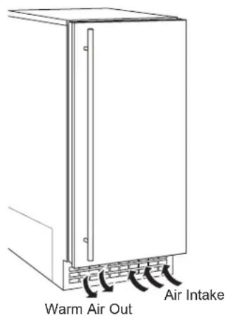
This machine takes in room temperature air at the lower right front and forces warm air out the lower left front. Restricting the airflow or operating the machine in a hot or cold environment will adversely affect the ability of the ice machine to make ice.
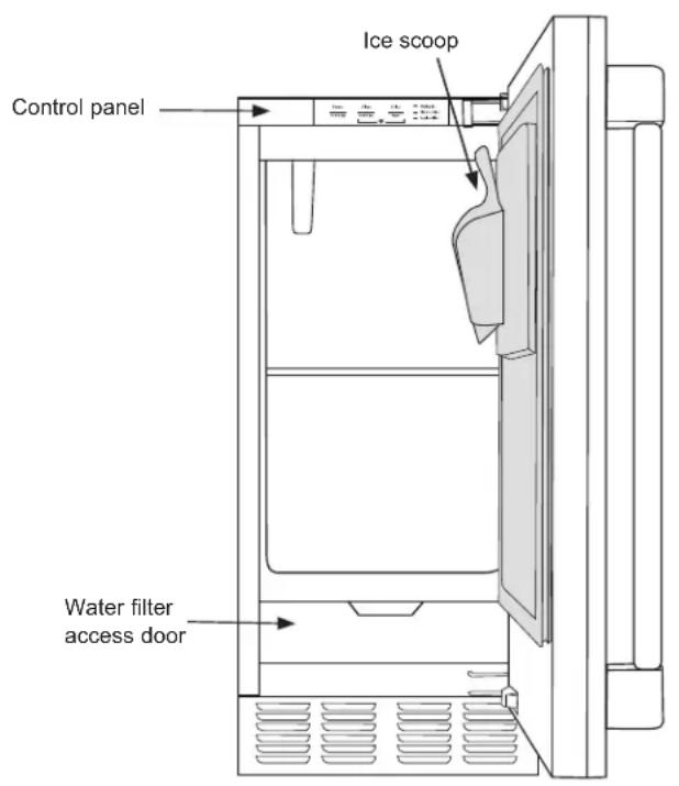
When the door is opened, the control panel, ice making area and ice storage bin are visible. The scoop is located in a holder on the inside of the door.
This is a gravity drain model that must have a building drain connection below the level of the drain tube at the back of the cabinet. A pump can be installed, which can force drain water up a maximum of 8 feet, allowing it to be located where a gravity drain isn't available. See Accessories on page 27 for more information on the drain pump.
Initial Start Up
- Turn on the water supply.
- Switch on the electrical power.
- Press and hold "Power" for 3 seconds to start the machine. The "Making Ice" light will turn on.
It will take about 20 minutes for the ice machine to begin dropping nugget ice into the storage bin. It is normal for that ice to melt and continue to melt but at a slower rate as the bin cools. It will take about 8-10 hours to fill up the ice storage bin. The storage bin holds about 26 lbs of ice when full.
Discard the first bin full of ice.
Installation Instructions
ICE MACHINE
Questions? Call 833-4BODEWELL (833-426-3393) or visit our Website at: GEAppliances.com
In Canada, call 1.800.561.3344 or visit our Website at: GEAppliances.ca
GROUNDING THE ICE MACHINE

WARNING

Electrical Shock Hazard.
Failure to follow these instructions can result in death, fire, or electrical shock.
The power cord of this appliance is equipped with a 3-prong (grounding) plug which mates with a standard 3-prong (grounding) wall outlet to minimize the possibility of electric shock hazard from this appliance.
Have the wall outlet and circuit checked by a qualified electrician to make sure the outlet is properly grounded.
Where a standard 2-prong wall outlet is encountered, it is your personal responsibility and obligation to have it replaced with a properly grounded 3-prong wall outlet.
DO NOT, UNDER ANY CIRCUMSTANCES, CUT OR REMOVE THE THIRD (GROUND) PRONG FROM THE POWER CORD.
DO NOT USE AN ADAPTER PLUG TO CONNECT THE APPLIANCE TO A 2-PRONG OUTLET.
DO NOT USE AN EXTENSION CORD WITH THIS APPLIANCE.
BEFORE YOU BEGIN
Read these instructions completely and carefully.
- IMPORTANT — Observe all governing codes and ordinances. Save these instructions for local inspector's use.
- Note to Installer – Be sure to leave these instructions with the Consumer.
- Note to Consumer – Keep these instructions for future reference.
- Skill level – Installation of this appliance requires basic mechanical skills.
- Completion time – Installation can vary Water Line Installation 30 minutes
- Proper installation is the responsibility of the installer.
- Product failure due to improper installation is not covered under the Warranty.
ICE MACHINE LOCATION AND PREPARATION
This ice machine is designed to be used indoors, in a controlled environment.
It is made up of two major systems: the ice making system and the ice storage system. The ice making system is a continuous flow that makes ice when the ice level becomes low and stops when it is full.
The ice storage system is an insulated chest with a drain at the bottom for melting ice. It is not refrigerated, insuring that the bin contains fresh ice.
During ice making, nugget ice will drop into the bin at an irregular rate; sometimes there will be little ice falling while other times a group of nuggets will fall.
IMPORTANT: Never keep anything in the ice storage bin that is not ice. Objects like wine or beer bottles are not only unsanitary, but the labels can slip off and plug up the drain.
IMPORTANT: Never allow the machine to operate without regular cleaning. The machine will last longer if it is kept clean. Regular cleaning should happen twice per year. Some water conditions will dictate even more frequent cleaning of the ice making section, and some carpets or pets will dictate more frequent cleaning of the condenser.
Specifications
The ice machine will operate adequately within the limits, but functions best in temperatures between 60^ F and 80^ F.
• Minimum air temperature: 55°F (12.8°C)
• Maximum air temperature: 100°F (38°C)
• Minimum water temperature: 40^ F ( 4.5^ C)
• Maximum water temperature: 90°F. (32°C)
• Minimum water pressure: 30 psi (1.06 bar)
• Maximum water pressure: 120 psi (8.27 bar)
Electrical voltage limits:
See the Rating Plate inside the ice machine.
ICE MACHINE LOCATION AND PREPARATION (Cont.)
Utility and Operational Requirements
- This ice machine must be connected to a potable water supply.
The water to this ice machine must be potable, or fit for human consumption. During ice making some minerals will stick to the ice making components. The higher the mineral content, the more mineral build up will occur. Water filters are a partial help, as they will remove the suspended solids, but water treatment is needed for the dissolved solids, which are part of the water and cannot be filtered out.
This machine can be supplied with Reverse Osmosis water, but the water conductivity must be no less than 10 microSiemens/cm. A reverse osmosis system should include post treatment or blending to satisfy the R.O. water's potential aggressiveness.
Deionized water is not recommended and could damage the machine.
Because water softeners exchange one mineral for another, softened water may not improve water conditions when used with ice machines.
Minimum recommended clearances: 0" on sides, 1/8" on top, 1 1/4" in back.
• Minimum water pressure: 30 psi
• Maximum water pressure: 120 psi
• Minimum water temperature: 40^ F
• Maximum water temperature: 90°F.
This ice machine is designed to operate in a wide range of air temperatures with a minimum air temperature of 55^ F and a maximum air temperature of 100^ F.
Although the machine will function within the listed ranges, it works best at water temperatures between 50^ F and 60^ F and air temperatures between 60^ F and 80^ F.
NOTE: Ice making capacity goes down as the environmental temperatures go up, and will be severely reduced at temperatures over 90°F.
Operating a unit outside of the limits can cause problems that are not covered by the warranty and, if extreme, cause damage to the unit.
This machine can be built into a cabinet. It is an air cooled refrigeration system. Air flows in and out of it through the grill at the bottom front. The grille must not be blocked by any covering door, or other obstruction.
ADVANCE PLANNING
CAUTION
Due to excessive weight, TWO PEOPLE ARE REQUIRED TO MOVE AND INSTALL THIS Ice
maker. Failure to do so can result in back or other injury.
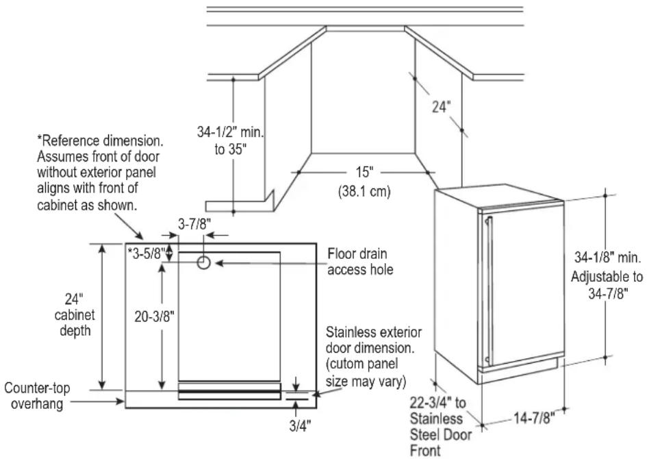
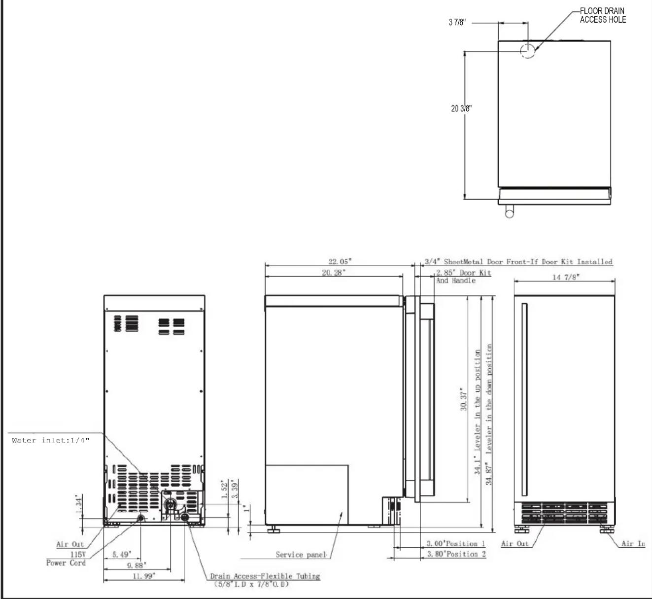
Cutout & Product Dimensions
Installation Notes
A drain pump is available for this ice machine. The drain pump kit number is UPK4 and is available at GEApplianceparts.com or by calling 877-959-8688. In Canada visit GEAppliances.ca or call 800.561.3344.
Built-In Installation: If a finished floor is to be installed in the area after the ice machine has been built in, shims the expected thickness of the floor should be installed under the unit to keep the machine level with the planned floor level.
NOTE: The water connection is at the back and adds a few inches to the cabinet depth.
Installation on a slab: You will need to install a drain pump to the appliance and pump the water to the point of drainage. See Accessories. Pumps will pump up to 8 feet high.
Installation over a crawl space or basement: Either a gravity drain or a pump may be used. For pump, see
Accessories. If there is not enough room behind the machine for a drain/waste receptacle, the drain will have to be below the floor.
NOTE: When installed in a corner, the door swing may be limited due to handle contact with the wall or cabinet face.
A water supply is required. Water supplies vary in the degree of mineral content. High mineral content water will require more frequent maintenance. Water filtration may improve the taste of the ice as well as cut down on some of the mineral build up.
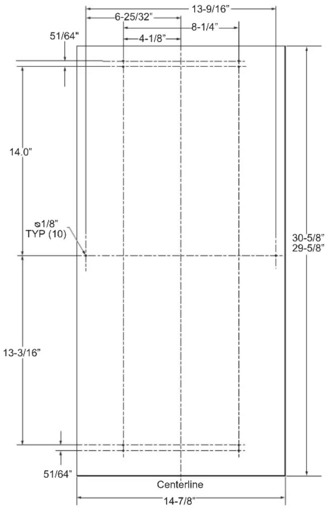
DIMENSIONS
DOOR SWING
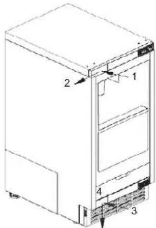
Moving the hinges allows the door to open from either the left or the right side. Change the swing BEFORE attaching the door panel.
- Remove the top and bottom hinge screw covers to gain access to the screws.
- Remove the hinge screws (4 total for top and bottom hinge).
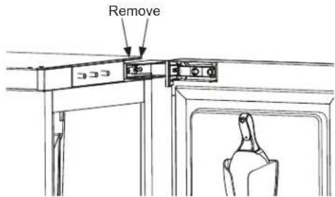
- Remove the door.
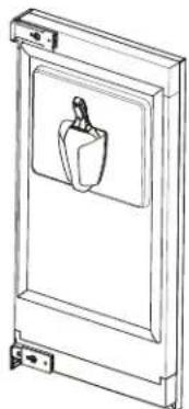
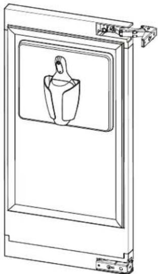
natural_image
Line drawing of a door frame with a hanging bell and handle (no text or symbols)-
Remove the door gasket and ice scoop.
-
Use a slotted screwdriver to pry on the snaps on the lower decorative cover at the 4 location shown in the figure.
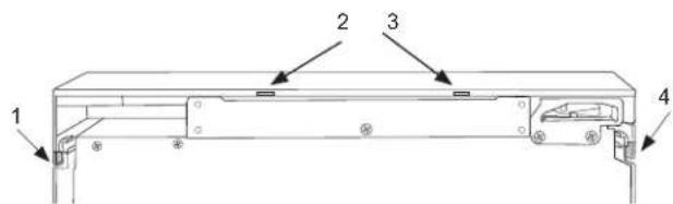
-
Remove the upper decorative cover in the same way.
-
Remove the top hinge and hinge cover. Remove the hinge cover from the hinge.
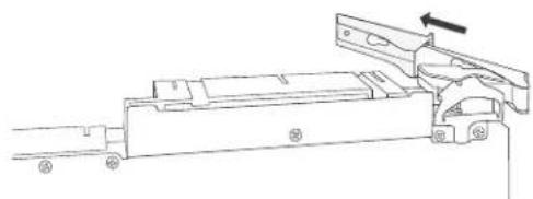
natural_image
Technical line drawing of a mechanical assembly with no visible text or symbols-
Remove the lower hinge and hinge cover. Remove the hinge cover from the hinge.
-
Slide the original top hinge cover on the original lower hinge and attach this assembly to the top, on the opposite side of the original location.
natural_image
Technical line drawing of a mechanical assembly with no visible text or symbols- Slide the original lower hinge cover on the original top hinge and attach this assembly to the lower hinge location, on the opposite side for the original location.
natural_image
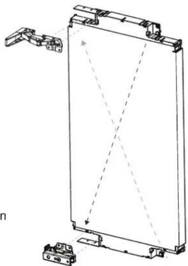
Technical line drawing of a mechanical frame assembly with mounting brackets and alignment lines (no text or symbols)Steps 8-11
DOOR SWING (Cont.)
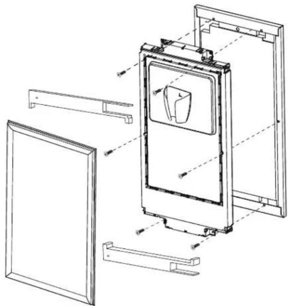
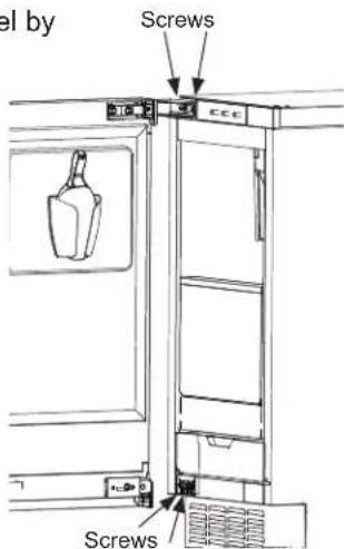
- Remove any plastic protective covering from the stainless door panel
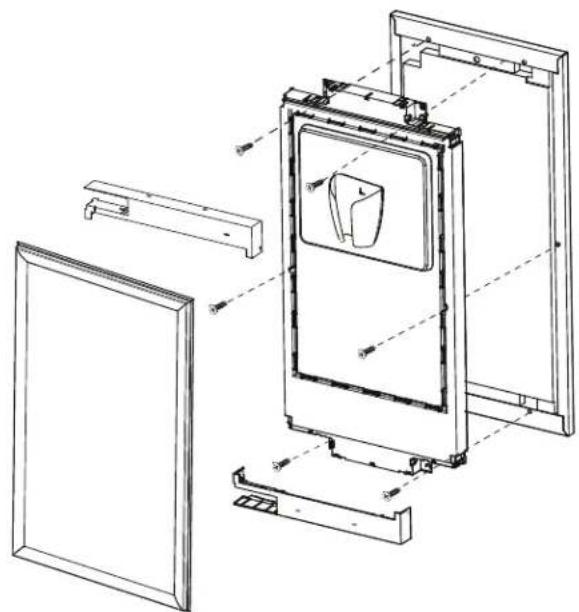
- Using a Phillips screwdriver, install the six screws (supplied with door panel kit) as shown in the figure to attach the inner panel to the exterior panel. Make sure the handle is located on the desired side.
natural_image
Technical line drawing of a door frame assembly with mounting brackets and internal components (no text or symbols)- Turn the upper decorative cover 180 degrees and snap in the lower position. Turn the lower decorative cover 180 degrees and snap in the upper position
- Replace the door gasket and ice scoop.
natural_image
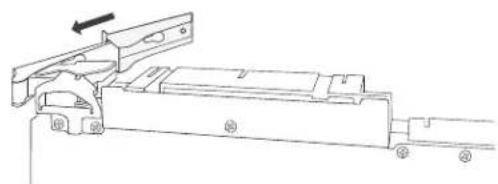
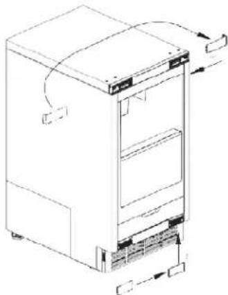
Technical line drawing of a door frame with a central vent and mounting bracket (no text or symbols)- Remove the upper hinge plate by pushing in and sliding to the outside and lower hinge plate by firmly pushing in and down as shown in the figure.
- Install the upper and lower hinge plates on the opposite side.
natural_image
Line drawing of a refrigerator with doors and refrigerators (no text or symbols)- Replace the door panel by installing the top and bottom hinges with the 4 screws.
INSTALLING THE DOOR PANEL
The ice machine is supplied without a conventional door covering, allowing the attachment of a door panel or a custom panel.
NOTE: If the door swing is to be changed, it needs to be done BEFORE attaching the door panel.
Door Panel
Finished door panels with handles are available from GE Appliances for attachment to the ice machine. See Accessories on page 27.
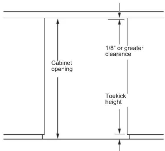
A custom panel of wood or other material not exceeding 15 lbs can be used and must follow these guidelines:
width: 14 7/8"
height: between 29 5/8" and 30 5/8"
thickness: 5/8" to 3/4"
For Custom Panel:
- Place product in opening and level by adjusting leveling legs as needed.
- Measure how much if any the custom panel needs to extend above the inner door panel to match any panels on either side. Note the clearance between the top of the panel and the countertop should be at least 1/8".
- Remove the door by removing the 4 hinge screws.
- Cut panel to the specified width and desired height.
- Lay panel on a surface and align the door on top of the panel so that it located as measured in step 2. The sides of the panel should align with the sides of the door.
- Mark locations of at least the 4 holes in the top and bottom. Remove the door and measure and mark any remaining holes per the diagram.
- Drill pilot holes on the back of the panel at your markings. Use a drill stop to prevent drilling through the panel.
INSTALLING THE DOOR PANEL (Cont)
If the door swing is going to be changed please complete prior to installing the door panel. See page 13. Depending on the door kit being installed, the door handle may need to be flipped if the door swing is being changed. Please see instructions on page 18 on how to flip the door handle.
Attaching the Door Panel
- Remove the gasket from the inside of the door and retain for later use.
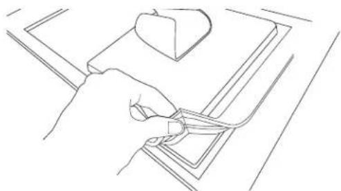
natural_image
Line drawing of a hand holding a tool near a small object on a surface (no text or symbols)- Identify the 4 pry tabs on the top and bottom decorative door trims.
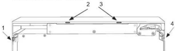
- Pry on each tab and pull down on the trim as shown until you can remove each of the trims.
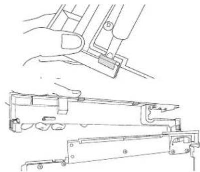
natural_image
Technical line drawing of a mechanical assembly with hands operating a tool (no text or symbols present)- Remove any plastic protective covering from the stainless door panel
- Place the door panel onto the outside of the door and secure it with 6 machine screws. (Provided in Door Panel Kit)
- Snap the upper and lower trims back on the inner panel.
- Re-install the door gasket.
natural_image
Technical line drawing of a door frame assembly with no visible text or symbolsINSTALLING THE DOOR PANEL (Cont)
▲WARNING
Door Hinge Pinch Point Hazard
Improper installation can lead to a finger pinch point hazard near the hinge when operating the door. For installations that are not under a counter, follow the installation instructions. A protective guard is provided for limiting access to the door hinge.
- On free-standing locations, attach the side covers from the hardware packet over the hinge by peeling off the covering over the adhesive and placing it over the side of the hinge. Note: If the unit is being built-in, a screw can be used to screw into the cabinet instead on installing the side covers.
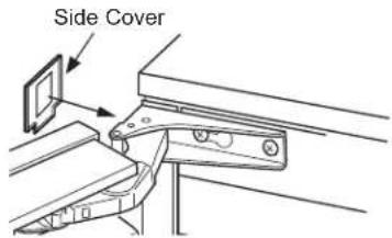
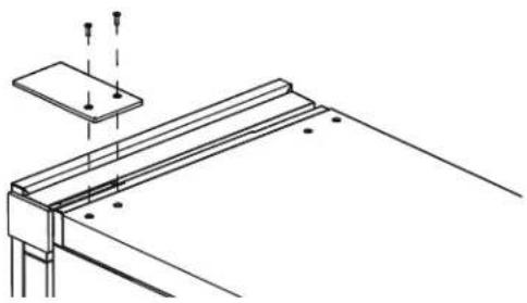
- Also on free standing applications, attach the top hinge cover from hardware packet with the 2 screws provided.
natural_image
Technical line drawing of a structural support frame with mounting holes and supports (no text or symbols)HANDLE REVERSING INSTRUCTIONS
- Remove the allen wrench from the panel installation screw kit envelope
- Loosen the set screw using the allen wrench. Remove the handle and flip it around so the logo is facing the other way.
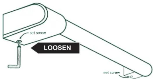
- Place the handle caps over the fasteners of the door. Take care to support the handle so it doesn't fall and scratch the appliance finish. Make sure both handle caps are resting on the face of the door.
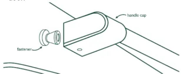
- Lock one end of the handle into position by tightening the set screw in the handle cap with the allen wrench provided. DO NOT over-tighten.
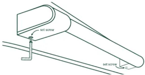
- Keep supporting the handle as you lock the other end of the handle into position by tightening the set screw in the handle cap. DO NOT over-tighten.
A drain pump is available for this ice machine. The drain pump kit number is UPK4 and is GEApplianceparts.com or by calling GE
Appliances at 877-959-8688. In Canada visit GEAppliances.ca or call 800.661.1616.
PLUMBING - GRAVITY DRAIN
Drain Installation
▲NOTICE
Restrictions in the drain
system to the machine will cause water to back up into the ice storage bin and melt the ice. Gravity drain tubing must be vented, have no kinks, and slope to the building drain. Air gaps are typically required by local codes.
A: Floor Drain Located Under Unit
- Place the unit (ice machine) in front of the installation opening. Adjust leveling legs to the appropriate height.
- Remove the left side (when facing the product) access panel to the drain connection.
- Remove the plastic cover/ plug in the base pan of the unit.
- Remove the clamp and rotate the barbed elbow on the drain tube so it will drain through the base pan and into the floor drain. Re-secure the clamp.
natural_image
Mechanical assembly diagram showing internal components and wiring (no text or labels)-
Reinstall the access panels.
-
While trying to locate the unit drain as close as possible to the floor drain, carefully push the unit into place.
PLUMBING - GRAVITY DRAIN (cont)
B: Floor Drain Located Off to the Side or Back of the Unit (not directly under the unit)
- Place the unit (ice machine) in front of the installation opening. Adjust leveling legs to the appropriate height.
- Remove the left side (when facing the product) access panel to the drain connection.
- Route 5/8" ID x 7/8" OD tygon tubing (clear plastic) through the hole in the lower back panel. Connect tubing to the barbed elbow and secure with a clamp. NOTE: Tubing and clamp are not included and must be purchased separately.
- Take care in measuring the amount of tubing needed to reach the floor drain and cut to desired length. NOTE: Ensure there is enough tubing to reach the drain but not too much to kink or bunch up when unit is moved into position.
natural_image
Technical line drawing of a mechanical assembly with no visible text or symbols- Reinstall the access panels.
Water Supply
The recommended water supply line is part number WX08X10006G. and is available at GEApplianceparts.com or by calling 877-959-8688. In Canada visit GEAppliances.ca or call 800.561.3344.
Install an easily accessible shut-off valve between the supply and the unit. This shut-off valve should not be installed behind the unit.
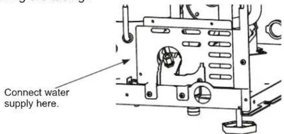
The water connection is at the back of the cabinet.
When built in: Coil enough tubing behind the machine so it can be pushed into the cavity without kinking the tubing.
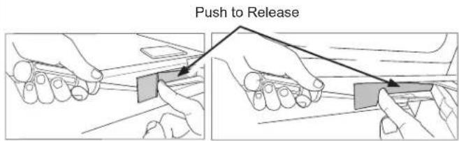
TOE KICK LOCATION
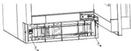
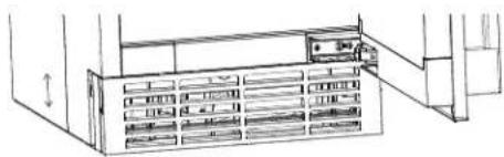
The toe kick can be adjusted to help align with your cabinets. The toe kick comes installed in the inward position. To move the toe kick to the outward position:
- Loosen the screws on both sides as shown to remove the metal toe kick.
natural_image
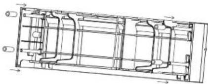
Technical line drawing of an electronic device with internal components and wiring (no text or symbols)- Loosen the 2 long screws in front and remove the plastic frame.
natural_image
Technical line drawing of a mechanical assembly with no visible text or symbols- Insert the bushings provided in the literature bag onto the posts on the rear of the frame as shown.
natural_image
Technical line drawing of a mechanical assembly with internal components and directional arrows (no text or labels)-
Re-install the plastic frame using the 2 long screws.
-
Re-install the metal toe kick using the 2 screws in the side. The toe kick can be adjusted up and down to your desired position.
natural_image
Line drawing of a server rack with multiple drive bays and a door open (no text or symbols)Drain Pump Kit UPK4 Accessory Installation
BEFORE YOU BEGIN
Read these instructions completely and carefully.
- IMPORTANT — Save these instructions for local inspector's use.
- IMPORTANT — Observe all governing codes and ordinances.
- Note to Installer – Be sure to leave these instructions with the Consumer.
- Note to Consumer – Keep these instructions for future reference.
- Skill level – Installation of this appliance requires basic mechanical skills.
- Proper installation is the responsibility of installer.
- Product failure due to improper installation is not covered under the Warranty.
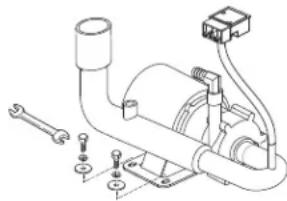
WHAT YOU WILL NEED:
3/8" open/box wrench or adjustable wrench
Drill with phillips head bit or #2 Phillips screwdriver
Slip joint pliers
Side cutting pliers
NOTE: This pump can be installed in a cube ice machine or a nugget ice machine.
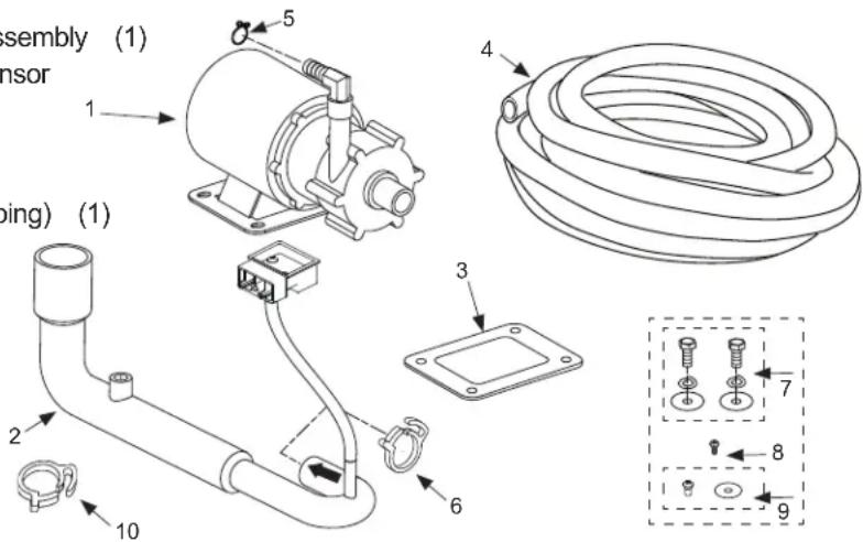
KIT CONTENTS:
1 - Drain Pump & Check Valve Assembly (1)
2 - PVC Drain Pipe & Pressure Sensor Assembly (1)
3 - Rubber Pad (For Pump Mounting) (1)
4 - Discharge Tubing - Clear (1)
5 - Metal Clamp (For Discharge Tubing) (1)
6 - Plastic Snap Ring (1)
7 - Pump Fixing Bolts (2);
Spring Washer (2); Flat Washer (2)
8 - Pressure Sensor Case Screw (ST/4*12) (1)
9 - Ground Screw With Washer (M/4*8) (1); Lock Washer(1)
10 - Small Plastic Snap Ring (1) (in some kit)
Drain Pump Kit UPK4 Accessory Installation (Cont.)
Death or serious injury can result from failure to follow these instructions.
• Service by a qualified service technician only.
- Disconnect power before servicing this product.
- Reconnect all grounding devices after service.
- Replace all parts and panels before operating.
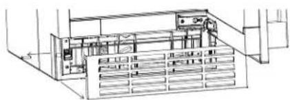
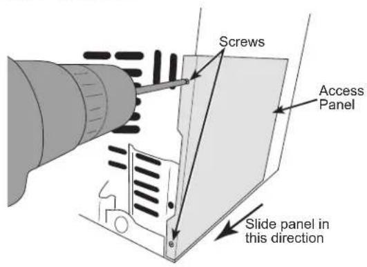
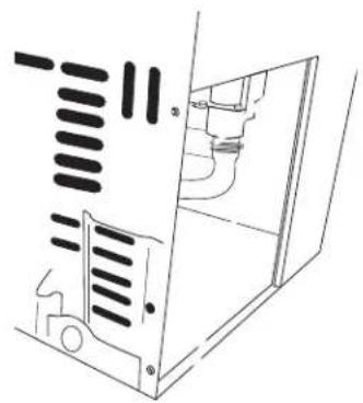
1 REMOVE ACCESS COVER
■ Use a drill or a Phillips screwdriver to remove the 2 screws from the access panel as shown in figure below. Slide the panel in the direction shown to remove.
natural_image
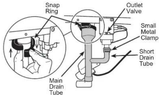
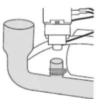
Technical line drawing of a mechanical assembly or housing with internal components (no text or symbols)2 REMOVE DRAIN TUBING
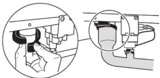
■ Remove the plastic snap ring from the main drain tube and release the small metal clamp on the short drain tube which connected outlet valve. Pull both tube down. Remove the small metal clamp from the tube. Keep both snap ring and clamp for pump kit installation
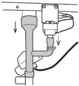
■ Remove the white drain pipe by pulling it down from the 2 locations shown.
natural_image
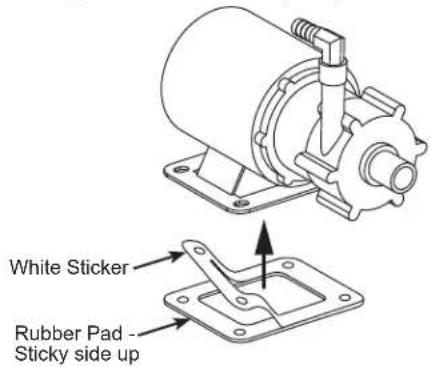
Diagram of a pipe connection with a valve and cable, showing fluid flow direction (no text or labels)3 INSTALL RUBBER PAD TO NEW PUMP
■ Remove the rectangular rubber pad from pump kit and peel off the white sticker. Attach the sticky side to the drain pump base.
Drain Pump Kit UPK4 Accessory Installation (Cont.)
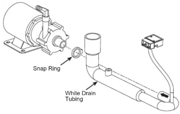
4 INSTALL NEW DRAIN TUBING
■ Install the new white drain tubing in the accessories to the drain pump and clamp with snap ring included in the kit. Please ensure that the side with arrow faces up during installation.
5 INSTALL THE DRAIN PUMP (Cont.)
■ Using the hardware from the kit, attach the pump to the ice maker floor using a wrench.
natural_image
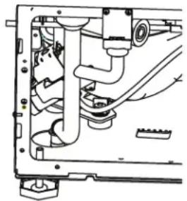
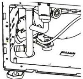
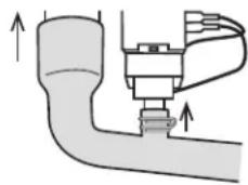
Technical line drawing of a mechanical assembly with no visible text or symbols6 CONNECT DRAIN PUMP TO ICE MACHINE
For pump kit without small plastic snap ring (item 10 in Pump kit content list).
■ Save the big plastic snap ring and the small metal clamp from original tube assembly.
■ Slide the small metal clamp on the short drain tube of the PVC pipe as shown in the picture below. Push the pipe up to connect both tubes to the fittings from the ice machine which you disconnected earlier. Snap and secure the big snap ring back and tighten on the connection of the main drain tube. Slide up and secure the small metal clamp up at the connection.
natural_image
Diagram of a mechanical valve assembly with upward arrows indicating force or movement (no text or labels)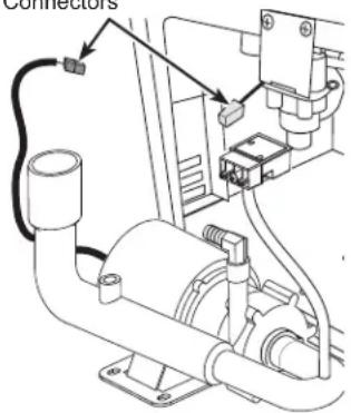
natural_image
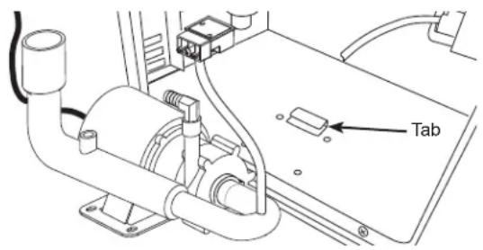
Mechanical assembly diagram showing a hand adjusting a component with a magnified inset (no text or symbols)■ Slide the drain pump into the ice machine so the base slides under the tab on the base of the ice machine floor. The front of the pump with the hose attached will face the front of the ice machine.
For pump kit coming with small plastic snap ring (item 10 in Pump kit content list),
■ Save the big plastic snap ring from original tube assembly and pick up the small plastic snap ring from pump package.
■ Push the PVC pipe up to connect both tubes to the fittings from the ice machine which you disconnected earlier. Snap and secure the 2 plastic snap rings, one large and one small, onto the connections and tighten on the drain tube.
Drain Pump Kit UPK4 Accessory Installation (Cont.)
6 CONNECT DRAIN PUMP TO ICE MACHINE (Cont.)
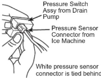
■ Locate the male 4-pin white pressure sensor connector behind the bracket hole, loosen the wire tie and connect the pig tail to the pressure sensor located on the drain tube assembly. If the male 4-pin white pressure sensor connector is not showing in the access opening area, locate the connector in the nearby machine compartment area and connect it to pressure sensor on the drain tube assembly. The 4-pin male connector within the ice machine will match up with the 4-pin female connector on the pressure sensor. NOTE: the yellow connector within the ice machine should not be used.
natural_image
Technical line drawing of a mechanical assembly with no visible text or symbols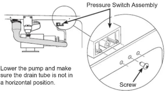
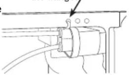
Lower the pump and make sure the drain tube is not in a horizontal position.
Attach the pressure sensor assembly in the 3 holes of the flange of the ice machine, as shown, using the screw provided with the kit.
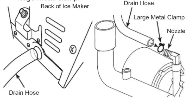
Thread the drain hose into the round hole in the back of the ice machine case and attach to the nozzle on the top of the drain pump using the large metal clamp.
6 CONNECT DRAIN PUMP TO ICE MACHINE (Cont.)
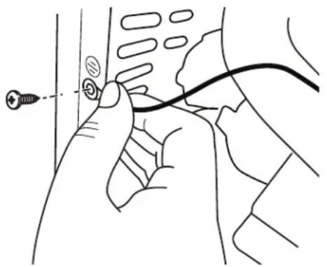
- IMPORTANT Ground the pump to the machine cabinet using the green ground wire and screw. The grounding hole is marked with a grounding symbol.
natural_image
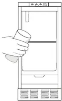
Line drawing of a hand holding a cable with a connector, no text or symbols present7 CHECK PUMP OPERATION (DO NOT SKIP THIS STEP)
■ Restore power to the unit.
■ Pour several quarts of water into the bin, the drain pump should turn on and pump the water out of the bin automatically, cycling on and off several times during the process is normal. Check the connections if pump had no response.
■ While the pump is discharging water, THOROUGHLY CHECK THE ENTIRE DRAIN SYSTEM FOR LEAKS.
natural_image
Line drawing of a hand holding a cup above a refrigerator (no text or symbols)8 FINALIZE INSTALLATION
■ Re-install side panel using the screws removed in step 1.
■ Re-install unit into built-in or free-standing location. ENSURE THAT NO KINKS OCCUR IN WATER INLET OR DRAIN TUBING. Double-check for leaks!
■ Restore potable water supply and restart the unit. Check unit to ensure proper operation and to allow a final check for leaks of any kind.
GSWF Water Filter
Water Filter Cartridge
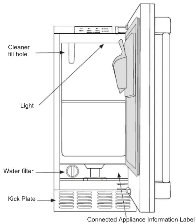
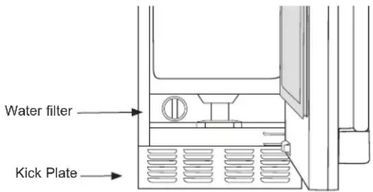
The water filter cartridge is located at the bottom of the icemaker behind the water filter access door.
When to Replace the Filter Cartridge
"Replace Filter" Indicator will come on when it is time to order a filter. This will occur after approximately 5 months or earlier after periods of heavy icemaking. To order additional filter cartridges, visit our website at gewaterfilters.com or call GE Appliances Parts and Accessories, 877.959.8688 and order filter GSWF.
"Replace Filter" Indicator will flash when it is time to replace the filter. This will occur after approximately 6 months or earlier after periods of heavy icemaking.
Replacing the Filter
- Open water filter access door by pulling on the top of the door until it flips open
- Gently grasp the filter and slowly turn it to the left about a 14 turn until you can pull it out. A small amount of water may drip out of the filter.
Filter Bypass Plug
If a replacement filter cartridge is not available, a bypass plug must be used in order for the icemaker to function. To obtain a bypass plug, call 833-4BODEWELL (833-426-3393) and request WR02X11613 filter bypass plug. In Canada, call 800.561.3344. The left side panel will need to be removed to install a filter bypass plug. Be sure to unplug the icemaker before trying to install a bypass plug.
Installing the Filter
- Open water filter access door by pulling on the top of the door until it flips open
- Insert filter until it aligns in the filter housing
- Slowly turn the filter to the right until it stops. DO NOT OVERTIGHTEN. As you turn the filter, it should automatically adjust itself into position. The filter will move about 14 turn or 90 degrees when in the correct position.
- Gently close the filter access door until it snaps into place
- Press and hold the "Filter Reset" button for 3 seconds to reset the filter timer/counter.
If you have questions, or to order additional filter cartridges, visit our website at gewaterfilters.com or call GE Appliances Parts and Accessories, 877.959.8688.
Care And Cleaning
Cleaning the Outside
The stainless steel door and door handle can be cleaned with a commercially available stainless steel cleaner. Cleaners with oxalic acid such as Bar Keepers Friend Soft Cleanser™ will remove surface rust, tarnish and small blemishes.
Use only a liquid cleanser free of grit and rub in the direction of the brush lines with a damp soft sponge. Do not use appliance wax or polish on the stainless steel.
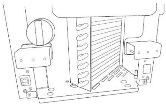
Cleaning the Condenser
The condenser has fins and tubes that can become clogged with dirt and lint.
To clean:
- Unplug the icemaker.
-
Remove the kickplate by removing the 2 screws in the sides of the metal grill, then 2 additional screws from the front of the kickplate. Pull kickplate forward to remove. To access top of condenser, remove door by removing the hinges from the cabinet. Open the water filter access door and remove 2 screws in the filter cover. Remove hinge cover plate on opposite side of hinge by firmly pressing in and sliding down. Pull filter cover forward to remove.
-
Vacuum the surface to remove all dust and lint.
▲NOTICE
Do not dent the fins.
- Re-install the filter cover, hinge cover plate, kick plate and door.
natural_image
Technical line drawing of a mechanical assembly with no visible text or symbols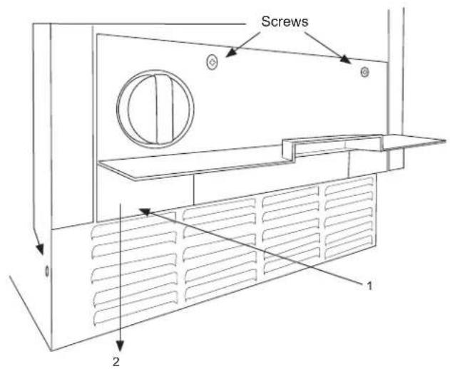
Removing Scale from the Ice Making System
Cleaning the ice machine involves adding a cleaner to the ice machine.
You should use rubber gloves when using the scale remover. To order cleaner, go to GEApplianceParts.com or call 877-959-8688. Order part number WX01X40745.
- If unit is on, press and hold the "Power" button for 3 seconds. The icemaking light will flash until icemaker has pushed out remaining ice in icemaking chamber.
- Scoop out and discard all of the ice in the ice bin.
- Press and hold Clean button for 3 seconds. The Time to Clean LED light will begin to slowly flash.
flowchart
graph LR
    A["Power"] --> B["Hold 3 Sec"]
    C["Clean"] --> D["Hold 3 Sec"]
    E["Filter"] --> F["Reset"]
    G["■ Making ice"] --> H["■ Time to Clean"]
    I["■ Replace Filter"] --> J["■"]
- After a few seconds, the Time to Clean LED light will begin to quickly flash and the buzzer will beep
indicating the need to add cleaner. Open the door and add one ounce of cleaner mixed with approximately 3 ounces of water into the water tank access hole in the upper left of the ice compartment as shown.
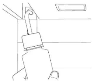
natural_image
Line drawing of a car seatbelt buckle (no text or symbols)- Press the Clean button. The Time to Clean LED light will start to flash slowly and the cleaning process will start The cleaning process will last approximately 40 minutes. When the clean cycle is complete, the Time to Clean LED light will turn off and the icemaker will return to the standby mode.
- Pour approximately 1/2 gallon of hot (95-115°F) water into the bin to flush out the bin and melt all ice made during the cleaning process.
- Mix one ounce of cleaner with one quart of water and clean the ice bin, interior door and gasket surfaces.
- Sanitize the bin and drain by pouring a mixture of 1 ounce of household bleach with 2 gallons of water into the bin.
- Rinse the bin again with hot water.
- Push and hold the Power button for 3 seconds to restart ice making.
The ice scoop should be washed regularly.
Winterizing
- With the icemaker in the Making Ice mode, open the door and push the Power button to turn the ice machine off. The "Making Ice" light will flash for about 2 minutes and the icemaker tank will automatically drain. (Make sure to turn off the icemaker in this way. If the icemaker is unplugged without first turning it off, the water in the tank will not drain.)
- Turn off the water supply.
Vacation
If you plan on being away for an extended period of time, it is recommended that you turn off icemaking.
-
Press and and hold "Power" for 3 seconds.
-
Models with a drain pump installed should have about 1/2 gallon of RV antifreeze (propylene glycol) poured into the ice storage bin drain.
NOTE: Automotive antifreeze must NOT be used. -
Turn off and unplug the machine.
NOTE: When placing the icemaker back in service after winterizing, it is recommended to complete the cleaning process on page 21. -
If icemaker is making ice when turned off, the Making Ice indicator will flash for 1 to 3 minutes to allow the icemaker to complete the icemaking process prior to turning off. The icemaker will also drain any water in the tank every time it is turned off.
Troubleshooting Tips... Before you call for service
Save time and money! Review the charts on the following pages first and you may not need to call for service.
| Problem Possible Causes What to Do | ||
| Low ice rate Restricted drain or standing water in the bin | Clean the air cooled condenser fins. | |
| Clean the ice making system. | ||
| Check the drain line for kinks | ||
| Room temperature may be high | ||
| No ice Power is OFF Press and hold | the "Power" button 3 | seconds to turn icemaking on. "Making Ice" light should turn on. |
| Electric breaker has been tripped Flip | the electric breaker back on If the breaker trips again, call service.. | |
| Water supply is low ("Making Ice" and "Filter" lights will flash alternately) | Check to make sure water supply is on or supply lines are not kinked. | |
| Component or sensor problem. (Different lights on control panel will be flashing) | Call service. | |
| Time to Clean light is on | Clean the ice making system following directions in the Care and Cleaning section. | |
| Water backs up into ice bin | Drain tubing is kinked | Use drain tubing that does not kink. |
Noise
The ice machine is designed for quiet operation but will make some noise during the ice making cycle.
GE Appliances Ice Machine Limited Warranty
GEAppliances.com
All warranty service is provided by our Factory Service Centers, or an authorized Customer Care® technician. To schedule service online, visit us at geappliances.com/service, or call GE Appliances at 833-4BODEWELL (833-426-3393). Please have your serial number and your model number available when calling for service. In Canada, visit GEAppliances.ca/en/support/service-request or call 800.561.3344
For the Period of: GE Appliances Will Replace
| One YearFrom the date of the original purchase | Any part of the ice machine which fails due to a defect in materials or workmanship.During the limited one-year warranty, GE Appliances will also provide, free of charge, all labor and related service to replace the defective part. |
| Five YearsFrom the date of the original purchase | Any part of the sealed refrigeration system (the compressor, condenser, evaporator and all connecting tubing) which fails due to a defect in materials or workmanship.During the limited five-year sealed refrigerating system warranty, GE Appliances will also provide, free of charge, all labor and related service to replace the defective part in the sealed refrigerating system. |
What GE Appliances Will Not Cover:
■ Service trips to your home to teach you how to use the product.
■ Improper installation, delivery or maintenance.
■ Failure of the product if it is abused, misused, or used for other than the intended purpose or used commercially.
■ Replacement of house fuses or resetting of circuit breakers.
■ Damage caused after delivery.
■ Replacement of the light bulbs, if included.
■ Damage to the product caused by accident, fire, floods or acts of God.
■ Incidental or consequential damage caused by possible defects with this appliance.
■ Product not accessible to provide required service.
EXCLUSION OF IMPLIED WARRANTIES
Your sole and exclusive remedy is product repair as provided in this Limited Warranty. Any implied warranties, including the implied warranties of merchantability or fitness for a particular purpose, are limited to one year or the shortest period allowed by law.
For US Customers: This limited warranty is extended to the original purchaser and any succeeding owner for products purchased for home use within the USA. If the product is located in an area where service by a GE Appliances Authorized Servicer is not available, you may be responsible for a trip charge or you may be required to bring the product to an Authorized GE Appliances Service location for service. In Alaska, the limited warranty excludes the cost of shipping or service calls to your home.
Some states do not allow the exclusion or limitation of incidental or consequential damages. This limited warranty gives you specific legal rights, and you may also have other rights which vary from state to state. To know what your legal rights are, consult your local or state consumer affairs office or your state's Attorney General.
Warrantor: GE Appliances, a Haier company
Louisville, KY 40225
For Customers in Canada: This limited warranty is extended to the original purchaser and any succeeding owner for products purchased in Canada for home use within Canada. In-home warrant service will be provided in areas where it is available and deemed reasonable by Mabe to provide.
Warrantor Canada: MC Commercial, Inc., Burlington, Ontario, L7R 5B6
Looking For Something More?
Finished stainless steel door panels with handles are available from GE Appliances for attachment to the ice machine. The panel kits are:
- ZK1UN150RSS - Stainless steel door without handle. The following Monogram handles are available for purchase separately:
- ZXGP1H1CPSS – Brushed stainless Minimalist handle - ZXGP1H1PWSS – Brushed stainless Statement handle
- PK1UG150RSS - Stainless steel door with Profile Style Handles
- CK1UP150RS1 - Stainless steel door with Café Style Handles
- CK1UP150RD1 - Matte black with Café style handle
- CK1UP150RW2 - Matte white with Café style handle
In addition we also offer the following Café handle kits:
• CXQW1H1PPBT - Black handle
• CXQW1H1PPBZ - Bronze handle
• CXQW1H1PPCU - Copper handle
• CXQW1H1PPSS - Stainless steel handle
NOTE: These kits only work with the CIP family of door kits.
To order, go to GEApplianceParts.com or call 877-959-8688. In Canada visit GEAppliances.ca/en/products/parts-filter-accessories or call 800.661.1616.
Drain Conversion: A gravity drain model can be converted to a drain pump model by installing a drain pump kit. The drain pump kit consists of a drain pump, wiring harness and associated tubing. The part number is UPK4. To order, go to GEApplianceParts.com or call 877-959-8688. In Canada visit
GEAppliances.ca/en/products/parts-filter-accessories or call 800.661.1616.
Consumer Support
GE Appliances Website
Have a question or need assistance with your appliance? Try the GE Appliances Website 24 hours a day, any day of the year! You can also shop for more great GE Appliances products and take advantage of all our on-line support services designed for your convenience. In the US: GEAppliances.com
In Canada: GEAppliances.ca
Register Your Appliance
Register your new appliance on-line at your convenience! Timely product registration will allow for enhanced communication and prompt service under the terms of your warranty, should the need arise. You may also mail in the pre-printed registration card included in the packing material. In the US: GEAppliances.com/register
In Canada: GEAppliances.ca/after-sales-support
Schedule Service
Expert GE Appliances repair service is only one step away from your door. Get on-line and schedule your service at your convenience any day of the year. In the US: bodewell.com/schedule-repair-service or call 833-4BODEWELL (833-426-3393) during normal business hours.
In Canada: GEAppliances.ca/after-sales-support or call 800.561.3344.
Extended Warranties
Purchase a GE Appliances extended warranty and learn about special discounts that are available while your warranty is still in effect. You can purchase it on-line anytime. GE Appliances Services will still be there after your warranty expires. In the US: bodewellcareplan.com or call 800.626.2224 during normal business hours.
In Canada: GEAppliances.ca/purchase-extended-warranty or call 866.277.9842.
Parts and Accessories
Individuals qualified to service their own appliances can have parts or accessories sent directly to their homes (VISA, MasterCard and Discover cards are accepted). Order on-line today 24 hours every day.
In the US: GEApplianceparts.com or by phone at 877.959.8688 during normal business hours.
In Canada: GEAppliances.ca/parts-filters-accessories or call 800.661.1616.
Instructions contained in this manual cover procedures to be performed by any user. Other servicing generally should be referred to qualified service personnel. Caution must be exercised, since improper servicing may cause unsafe operation.
Contact Us
If you are not satisfied with the service you receive from GE Appliances, contact us on our Website with all the details including your phone number, or write to:
In the US: General Manager, Customer Relations | GE Appliances, Appliance Park | Louisville, KY 40225
GEAppliances.com/contact or call 800.626.2000
In Canada: Director, Customer Relations | MC Commercial Inc. | Suite 300, 5420 North Service Road | Burlington, ON L7L 6C7
GEAppliances.ca/contact-us or call 877.994.5366
MACHINE À GLAÇONS
INFORMATION DE SÉCURITÉ...3
UTILISANT LA MACHINE À GLAÇONS
Déballage 6
Commandes 6
Fonctions 8
SENS D'OUVERTURE DE LA PORTE
natural_image
Illustration of two hands using a tool to adjust or install a component, showing alignment and assembly (no text or symbols)natural_image
Technical line drawing of a mechanical assembly with no visible text or symbolsnatural_image
Technical line drawing of a mechanical assembly with no visible text or symbolsnatural_image
Line drawing of a door latch with a bell jar on top (no text or symbols)natural_image
Technical line drawing of a mechanical assembly with mounting brackets and a dashed alignment line (no text or symbols)Steps 8-11
SENS D'OUVERTURE DE LA PORTE (suite)
natural_image
Technical line drawing of a door frame assembly with mounting brackets and internal components (no text or symbols)natural_image
Technical line drawing of a door lock mechanism with a central vent (no text or symbols)natural_image
Line drawing of a refrigerator interior showing front and rear panels with scroll arrows indicating movement (no text or symbols)INSTALLER LE PANNEAU DE PORTE (suite)
natural_image
Line drawing of a hand holding a small object over a rectangular panel (no text or symbols)natural_image
Technical line drawing of a mechanical assembly with hands and components (no text or symbols)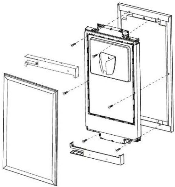
natural_image
Technical line drawing of a refrigerator internal frame with mounting brackets and door panel (no text or symbols)INSTALLER LE PANNEAU DE PORTE (suite)
AVERTISSEMENT

natural_image
Technical line drawing of a mechanical bracket assembly with mounting holes and a close-up detail (no text or symbols)natural_image
Technical line drawing of a structural frame with mounting holes and support beams (no text or symbols)INSTRUCTIONS RELATIVES À L'INVERSION DE LA POIGNÉE
natural_image
Mechanical assembly diagram showing internal components and gears (no text or labels)natural_image
Technical line drawing of a mechanical assembly with no visible text or symbolsnatural_image
Technical line drawing of a mechanical assembly with no visible text or symbolsEMPLACEMENT DU COUP-DE-PIED
natural_image
Technical line drawing of a mechanical assembly with no visible text or symbolsnatural_image
Technical line drawing of a mechanical assembly with internal components and directional arrows (no text or symbols)natural_image
Line drawing of a cabinet or rack with an open door and internal compartments (no text or symbols)Installation de la trousse de pompe de vidange UPK4 en accessoire
AVANT DE COMMENCER
Installation de la trousse de pompe de vidange UPK4 en accessoire (suite)
1 DÉBRANCHER L'ALIMENTATION ÉLECTRIQUE
AVERTISSEMENT

Risque
d'électrocution
natural_image
Technical line drawing of a mechanical assembly with internal components (no text or symbols)2 RETIRER LE TUYAU DE VIDANGE
natural_image
Diagram of a mechanical assembly with pipes and cables, no text or symbols present3 INSTALLER LE COUSSINET EN CAOUTCHOUC SUR LA NOUVELLE POMPE
natural_image
Technical line drawing of a mechanical pump assembly with no visible text or symbols6 RACCORDER LA POMPE DE VIDANGE À LA MACHINE À GLAÇONS
natural_image
Technical illustration of a mechanical assembly with four views: top view, side view, close-up of hands operating a tool, and bottom view (no text or symbols)5 INSTALLER LA POMPE DE VIDANGE
natural_image
Illustration of a hand holding a cable with a screwdriver inserted, showing no text or symbols7 VÉRIFIER LE FONCTIONNEMENT DE LA POMPE (NE SAUTEZ PAS CETTE ÉTAPE)
natural_image
Line drawing of a hand holding a cup inside a refrigerator (no text or symbols)8 TERMINER L'INSTALLATION
natural_image
Technical line drawing of a mechanical assembly with no visible text or symbolsnatural_image
Line drawing of a door handle with a lock mechanism (no text or symbols)electromenagersGE.ca
Garant : GE Appliances, a Haier company
Louisville, KY 40225
Garant Canada: MC Commercial, Inc., Burlington, Ontario, L7R 5B6
Au Canada : Director, Customer Relations | MC Commercial Inc. | Suite 300, 5420 North Service Road | Burlington, ON L7L 6C7 electromenagersge.ca/contactez-nous ou composer le 877.994.5366
INSTRUCIONES
DE SEGURIDAD....3
USO DE LA MÁQUINA DE HIELO
Embalaje 6
Controles 6
Funciones 8
natural_image
Technical line drawing of a door frame assembly with mounting brackets and internal components (no text or symbols)natural_image
Technical line drawing of a door frame with a central handle and mounting bracket (no text or symbols)natural_image
Technical line drawing of a refrigerator with doors and refrigerators (no text or symbols)natural_image
Line drawing of a hand holding a small object over a rectangular panel (no text or symbols)natural_image
Technical line drawings of a hand operating a tool and a mechanical device (no text or symbols present)natural_image
Technical line drawing of a door frame assembly with no visible text or symbolsnatural_image
Technical line drawing of a mechanical bracket assembly with mounting holes and a close-up detail (no text or symbols)natural_image
Technical line drawing of a structural frame with support beams and a flat panel (no text or symbols)natural_image
Technical line drawing of a mechanical assembly with no visible text or symbolsnatural_image
Technical line drawing of a mechanical assembly with no visible text or symbolsnatural_image
Technical line drawing of a cabinet or enclosure structure with internal components and mounting points (no text or symbols)natural_image
Technical line drawing of a mechanical assembly with internal components and directional arrows (no text or labels)natural_image
Line drawing of a cabinet or rack unit with shelves and doors, no text or symbols presentnatural_image
Technical line drawing of a mechanical assembly with internal components (no text or symbols)2 RETIRE LA TUBERÍA DE DESAGÜE
natural_image
Diagram of a pipe valve assembly with arrows indicating force or movement (no text or labels)3 INSTALE LA ALMOHADILLA DE GOMA EN LA BOMBA NUEVA
natural_image
Technical line drawing of a mechanical device with bolts and components (no text or symbols)6 CONECTE LA BOMBA DE DESAGÜE A LA MÁQUINA DE HIELO
5 INSTALE LA BOMBA DE DESAGÜE
natural_image
Pure technical diagram of a mechanical assembly with no visible text, numbers, or symbolsnatural_image
Illustration of a hand holding a cable with a screwdriver inserted, showing mechanical components (no text or symbols)7 CONTROLE EL FUNCIONAMIENTO DE LA BOMBA (NO SALTEE ESTE PASO)
natural_image
Line drawing of a hand holding a cup over a refrigerator (no text or symbols)natural_image
Technical line drawing of a mechanical assembly with no visible text or symbolsnatural_image
Line drawing of a car seatbelt buckle (no text or symbols)Warrantor: GE Appliances, a Haier company
Louisville, KY 40225
¿Busca Algo Más?
GEAppliances.com/service
GEAppliances.com/extended-warranty
General Manager, Customer Relations | GE Appliances, Appliance Park | Louisville, KY 40225
GEAppliances.com/contact o comuníquese al 800.626.2000
- SAFETY INFORMATION .... 3
- USING THE ICE MACHINE
- INSTALLATION INSTRUCTIONS
- CARE AND CLEANING....24
- TROUBLESHOOTING TIPS ..... 27
- LIMITED WARRANTY....28
- ACCESSORIES 29
- CONSUMER SUPPORT .... 32
- OWNER'S MANUAL AND INSTALLATION INSTRUCTIONS
- ENGLISH/FRANÇAIS/ ESPAÑOL
- THANK YOU FOR MAKING GE APPLIANCES A PART OF YOUR HOME.
- IMPORTANT SAFETY INFORMATION READ ALL INSTRUCTIONS BEFORE USING THE APPLIANCE
- WARNING
- CAUTION
- INSTALLATION
- XPLOSION HAZARD
- READ AND SAVE THESE INSTRUCTIONS
- ▲WARNING
- RE OR EXPLOSION HAZARD
- Flammable Refrigerant
- CONNECTING ELECTRICITY
- .ECTRICAL SHOCK HAZARD
- PROPER DISPOSAL OF YOUR OLD APPLIANCE
- SUFFOCATION AND CHILD ENTRAPMENT HAZARD
- REFRIGERANT AND FOAM DISPOSAL:
- Packaging
- Remove Packaging
- Controls
- Sabbath Mode
- Door Alarm
- Appliance Communication
- WiFi (for customers in the United States, its territories, and Canada)
- Icemakers Models with Password Label:
- Icemakers Models with UPD ID Label:
- Regulatory Information
- FCC/IC Compliance Statement:
- Features
- Starting the ice machine
- Initial Start Up
- ICE MACHINE
- GROUNDING THE ICE MACHINE
- Electrical Shock Hazard.
- BEFORE YOU BEGIN
- ICE MACHINE LOCATION AND PREPARATION
- Specifications
- Electrical voltage limits:
- ICE MACHINE LOCATION AND PREPARATION (Cont.)
- Utility and Operational Requirements
- ADVANCE PLANNING
- Installation Notes
- DOOR SWING
- DOOR SWING (Cont.)
- INSTALLING THE DOOR PANEL
- Door Panel
- For Custom Panel:
- INSTALLING THE DOOR PANEL (Cont)
- Attaching the Door Panel
- Door Hinge Pinch Point Hazard
- HANDLE REVERSING INSTRUCTIONS
- PLUMBING - GRAVITY DRAIN
- Drain Installation
- ▲NOTICE
- A: Floor Drain Located Under Unit
- PLUMBING - GRAVITY DRAIN (cont)
- B: Floor Drain Located Off to the Side or Back of the Unit (not directly under the unit)
- Water Supply
- TOE KICK LOCATION
- Drain Pump Kit UPK4 Accessory Installation
- WHAT YOU WILL NEED:
- KIT CONTENTS:
- Drain Pump Kit UPK4 Accessory Installation (Cont.)
- REMOVE ACCESS COVER
- REMOVE DRAIN TUBING
- INSTALL RUBBER PAD TO NEW PUMP
- INSTALL NEW DRAIN TUBING
- INSTALL THE DRAIN PUMP (Cont.)
- CONNECT DRAIN PUMP TO ICE MACHINE
- CONNECT DRAIN PUMP TO ICE MACHINE (Cont.)
- CHECK PUMP OPERATION (DO NOT SKIP THIS STEP)
- FINALIZE INSTALLATION
- GSWF Water Filter
- Water Filter Cartridge
- When to Replace the Filter Cartridge
- Replacing the Filter
- Filter Bypass Plug
- Installing the Filter
- Care And Cleaning
- Cleaning the Outside
- Cleaning the Condenser
- To clean:
- Removing Scale from the Ice Making System
- Winterizing
- Vacation
- Troubleshooting Tips... Before you call for service
- Noise
- GE Appliances Ice Machine Limited Warranty
- GEAppliances.com
- What GE Appliances Will Not Cover:
- EXCLUSION OF IMPLIED WARRANTIES
- Looking For Something More?
- Consumer Support
- GE Appliances Website
- Register Your Appliance
- Schedule Service
- Extended Warranties
- Parts and Accessories
- Contact Us
- MACHINE À GLAÇONS
- INFORMATION DE SÉCURITÉ...3
- UTILISANT LA MACHINE À GLAÇONS
- SENS D'OUVERTURE DE LA PORTE
- SENS D'OUVERTURE DE LA PORTE (suite)
- INSTALLER LE PANNEAU DE PORTE (suite)
- AVERTISSEMENT
- INSTRUCTIONS RELATIVES À L'INVERSION DE LA POIGNÉE
- EMPLACEMENT DU COUP-DE-PIED
- Installation de la trousse de pompe de vidange UPK4 en accessoire
- AVANT DE COMMENCER
- Installation de la trousse de pompe de vidange UPK4 en accessoire (suite)
- DÉBRANCHER L'ALIMENTATION ÉLECTRIQUE
- Risque
- d'électrocution
- RETIRER LE TUYAU DE VIDANGE
- INSTALLER LE COUSSINET EN CAOUTCHOUC SUR LA NOUVELLE POMPE
- RACCORDER LA POMPE DE VIDANGE À LA MACHINE À GLAÇONS
- INSTALLER LA POMPE DE VIDANGE
- VÉRIFIER LE FONCTIONNEMENT DE LA POMPE (NE SAUTEZ PAS CETTE ÉTAPE)
- TERMINER L'INSTALLATION
- electromenagersGE.ca
- INSTRUCIONES
- USO DE LA MÁQUINA DE HIELO
- RETIRE LA TUBERÍA DE DESAGÜE
- INSTALE LA ALMOHADILLA DE GOMA EN LA BOMBA NUEVA
- CONECTE LA BOMBA DE DESAGÜE A LA MÁQUINA DE HIELO
- INSTALE LA BOMBA DE DESAGÜE
- CONTROLE EL FUNCIONAMIENTO DE LA BOMBA (NO SALTEE ESTE PASO)
- ¿Busca Algo Más?
Brand : Café
Model : UNC15NPWII
Category : Ice machine