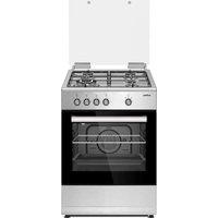
OR-649-XE - Cooker Orima - Free user manual and instructions
Find the device manual for free OR-649-XE Orima in PDF.


| Product type | Mixed gas/electric cooker |
| Brand | Orima |
| Model | OR-649-XE |
| Dimensions (W x D x H) | 600 x 630 x 855 mm (60x60 model) |
| Oven capacity | 60 L (depending on model, up to 80 L) |
| Power supply | 220-240 V ~ 50/60 Hz or 380-415 V 3N~ 50/60 Hz |
| Gas supply | Natural gas G20/G25 or LPG G30/G31 (depending on configuration) |
| Gas burner type | 1 wok burner (4.5 kW), 1 large (2.9 kW), 1 medium (1.7 kW), 1 small (0.95 kW) |
| Electric oven functions | Fan forced, grill, rotisserie, defrost, lighting |
| Timer | Mechanical or digital depending on version |
| Ignition | Automatic by button or manual |
| Gas safety device | Flame failure device (FFD) on each burner |
| Included accessories | Deep tray, standard tray, metal grill, drip tray, rotisserie, wok adapter |
| Cleaning | Steam cleaning, anti-odor catalytic panels |
| Door material | Tempered glass (double or triple glazing) |
| Interior lighting | Halogen bulb 15-25 W, energy class G |
| Electrical protection class | Class I (mandatory grounding) |
| Approximate weight | Approximately 45-55 kg depending on model |
| Energy consumption (oven) | Not specified, but compliant with European standards |
| Available spare parts | Injectors, bulbs, door seals, heating elements, thermostats, catalytic panels |
| Repairability | Repairability index not disclosed, parts available through authorized after-sales service |
| General information | Domestic use only, operational lifespan 10 years, installation by authorized professional |
Frequently Asked Questions - OR-649-XE Orima
User questions about OR-649-XE Orima
0 question about this device. Answer the ones you know or ask your own.
Ask a new question about this device
Download the instructions for your Cooker in PDF format for free! Find your manual OR-649-XE - Orima and take your electronic device back in hand. On this page are published all the documents necessary for the use of your device. OR-649-XE by Orima.
USER MANUAL OR-649-XE Orima
natural_image
Abstract red spiral logo with a gray crescent shape (no text or symbols)orima
eletrodomésticos
MANUAL
DE
INSTRUÇÕES
INSTRUCTION MANUAL
LIVRE D'INSTRUCTIONS
facebook.com/orima.pt
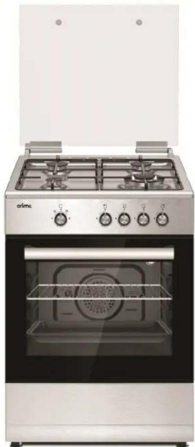
natural_image
Exterior view of a modern stainless steel electric oven with four gas stove units (no visible text or symbols)
MMA
MÁRIO MÍRANDA DE ALMEIDA
FOGÃO
Cooker | Estufa | Cuisinière
OR-649-XE
SERVIÇO DE APOIO AO CLIENTE
Apoio ao Cliente:
Tel.: (+351) 231 467 436 E: apoiocliente@orima.pt
Serviço Pós Venda:
Tel.: (+351) 231 467 427 E: assistencia@orima.pt
UK Thank you for purchasing this ORIMA product. Please read this manual carefully before using the appliance.
natural_image
Prohibition sign showing a crossed diagonal line crossing over a circular background with flame-like patterns (no text or symbols)natural_image
Warning symbol depicting a person pushing a large block inside a triangle (no text or numbers)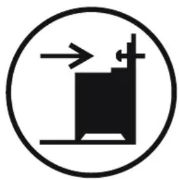
natural_image
Simple black-and-white diagram of a vertical structure with an arrow pointing upward, enclosed in a circle (no text or symbols)natural_image
Line drawing of a hand holding a small object near a vertical rod, enclosed in a circle (no text or symbols)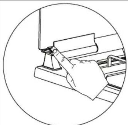
natural_image
Line drawing of a hand using a tool to press or install a component, enclosed in a circular frame (no text or symbols)Figura 2 Figura 3 Figura 1
natural_image
Line drawing of a hand using a tool to adjust or install a component on a workbench (no text or symbols)natural_image
Technical line drawing of a refrigerator interior showing front and side views (no text or symbols)natural_image
Hand holding a switch with directional arrows indicating movement (no text or symbols)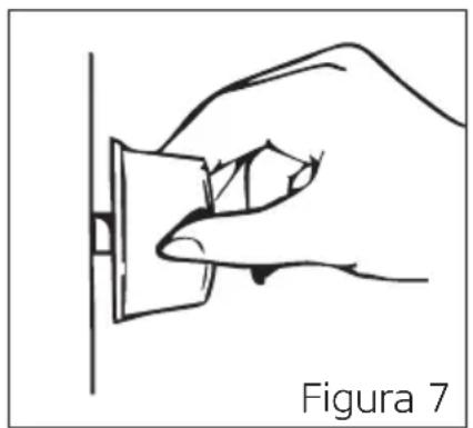
natural_image
Line drawing of a hand holding a small object against a vertical line, labeled 'Figura 7' (no other text or symbols)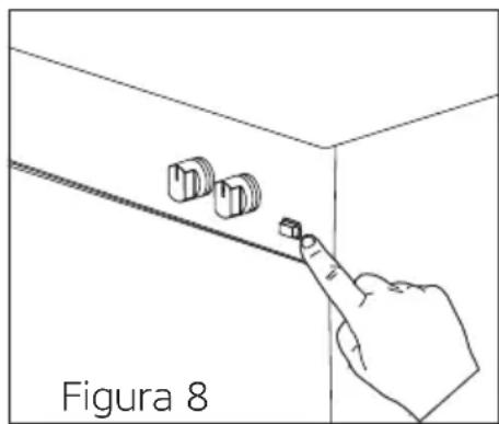
natural_image
Line drawing of a hand pressing down on a wall-mounted knob, labeled 'Figura 8' (no other text or symbols)natural_image
Technical illustration showing a mechanical component before and after assembly, with no visible text or symbols.POSIÇÕES DA PRATELEIRA
natural_image
Line drawing of a kitchen appliance with a circular lid and handle, no text or symbols presentFigura 12
natural_image
Line drawing of a mechanical component with a circular top and horizontal supports, no text or symbols presentFigura 13
natural_image
Hand holding a small object with arrows indicating movement or force direction (no text or symbols)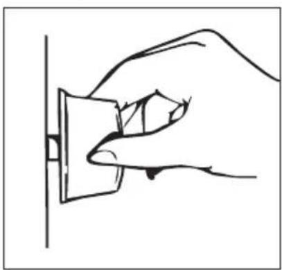
natural_image
Line drawing of a hand inserting a plug into a socket (no text or symbols)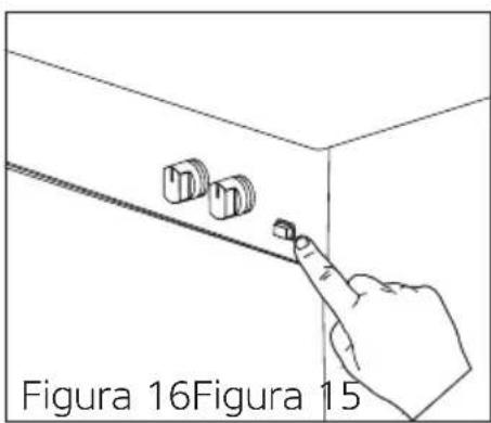
natural_image
Pure technical diagram showing a circular component with two black arrows pointing outward, no text or symbols present.Figura 17

natural_image
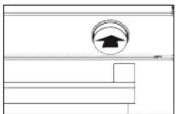
Pure electrical circuit lines without any symbolsFigura 18
natural_image
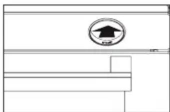
Pure technical diagram showing a circular component with an upward arrow, no text or symbols presentFigura 19
natural_image
Pure technical line drawing of a mechanical component with no text or symbolsFigura 20
natural_image
Technical line drawing of a mechanical or electrical enclosure with a central circular component and a circular base (no text or symbols)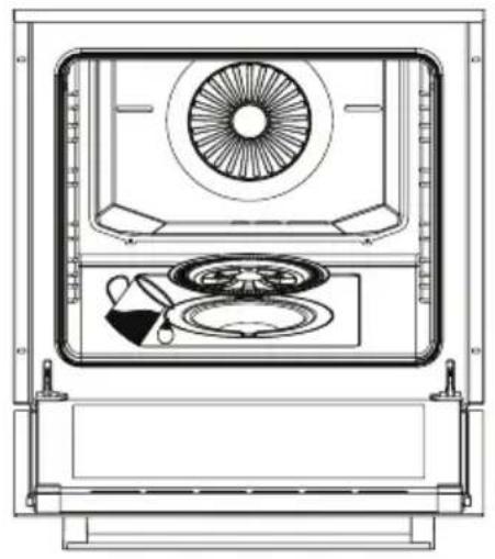
natural_image
Technical line drawing of a front view of a microwave oven with fan, dish, and control panel (no text or labels)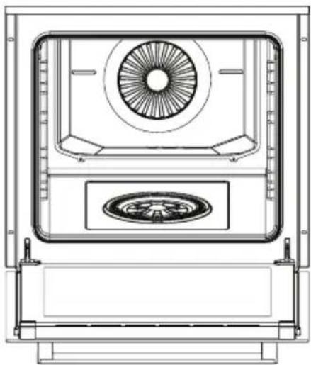
natural_image
Technical line drawing of a mechanical or electrical enclosure with a central fan and circular base (no text or symbols)Figura 21 Figura 23Figura 22
natural_image
Technical line drawing of a mechanical assembly with arrows indicating motion direction (no text or symbols)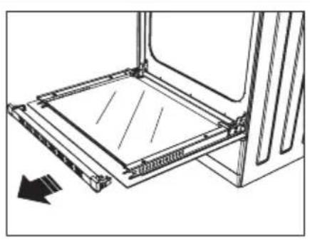
natural_image
Technical line drawing of a mechanical assembly with a rectangular frame and directional arrow (no text or symbols)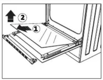
Figura 24 Figura 25 Figura 26
natural_image
Diagram of a mechanical component with a rotating arrow indicating rotational motion (no text or symbols)Figura 29
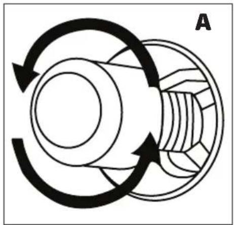
natural_image
Diagram of a mechanical gear or cam mechanism with rotational arrows indicating motion (no text or symbols)Figura 30
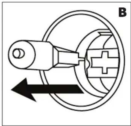
natural_image
Pure mechanical diagram showing a lever and gear mechanism without any text or symbolsFigura 31
natural_image
Symbol of a trash bin crossed with a diagonal line and a horizontal bar below (no text or labels)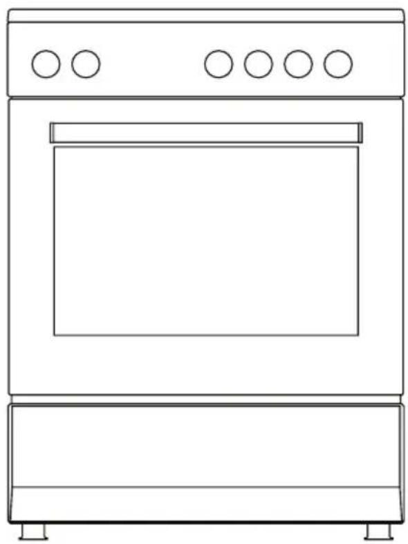
natural_image
Line drawing of a simple kitchen oven with five circular ovens on top (no text or symbols)Free Standing Oven
Gas and electric
50x55 / 50x60 / 56x57 / 60x60 / 60x60 Professional
User manual
Dear Customer,
Thank you for relying on this product.
We aim to ensure that you optimally and efficiently use this product produced in our modern facilities under environmentally friendly and precise conditions with respect to total sense of quality.
We recommend that you read the user manual carefully and keep it permanently before using your oven so that it retains its original features for a long time.
WARNING: This user manual is prepared for multiple models. Your appliance may not feature some functions specified in the manual.
Our appliances are intended for domestic use. It is not intended for commercial use.
The figures in the manual are schematic and may not be in exact harmony with your product.
This product has been produced in modern environment-friendly facilities without harmfully affecting the nature.
Features marked with * are optional.
"Complies with WEEE Regulation"
Contents
Important warnings 4
Power connection 18
Gas connection 21
Appliance introduction____ 28
Accessories 29
Technical specifications 33
Setting up the appliance 37
Control panel 43
Operation of the oven 50
Using the hob section____ 59
Cooking functions and features 66
Cooking recommendations and warnings 68
Cooking charts____ 71
Maintenance and cleaning 83
Oven lamp replacement 90
Troubleshooting 92
Handling rules 94
Recommendations for energy saving 95
Compliance with WEEE regulations and waste disposal____ 96
Package information____ 96
IMPORTANT WARNINGS
- Please read this user manual carefully. Only by this way you can use the appliance safely and in a correct manner.
- Installation and repair should always be performed by "AUTHORISED SERVICE". Manufacturer shall not be held responsible for operations performed by unauthorised persons.
- The configuration conditions of this appliance are specified on the type label or on the data plate.
- This appliance has been designed for household use only.
- WARNING: Fire hazard; do not place any object on the cooking surfaces.
- WARNING: The appliance and its accessible parts are hot during operation.
- WARNING: The accessible parts may be hot when the grill is used. Small children should be kept away.
-
WARNING: This appliance is intended for cooking. It should not be used for other purposes like heating a room.
-
WARNING: Burning hazard due to superheated steam! A child's skin is more sensitive to high temperature than an adult's. Children should not open the oven's door while the oven is operating. Keep the children away from the appliance until it is cooled down completely and burning hazard is avoided.
- WARNING: Never try to put out the fire with water. Only shut down the device circuit and then cover the flame with a cover or a fire blanket.
- ATTENTION: Cooking process shall be supervised. Cooking process shall always be supervised.
- ATTENTION: If the glass of the appliance is broken, turn off any heating element immediately and disconnect the appliance from power source, do not use the appliance.
- BURN RISK: As you open the oven door, step back to avoid the hot vapour coming out from the interior.
- BURN RISK: Hot surface should be left for cooling down before closing the cover.
15. BURN RISK: Hot surface should be left for cooling down before closing the cover.
- The appliance is not suitable for use with an external timer or a separate remote control system.
- To prevent overheating, the appliance should not be installed behind a decorative cover.
- This appliance can be used by children, who are 8 years old and above, and people with physical, hearing or mental challenges or people with lack of experience or knowledge; as long as a supervision is ensured or the appliance is used safely and information is provided for understanding the hazards involved.
- Keep children below the age of 8 and pets away when operating.
- Children under 8 years of age should be kept away, if they cannot be monitored continuously.
- Children should not play with the appliance. Cleaning or user maintenance of the appliance shall not be performed by children unless they are older than 8 years and supervised by adults.
-
Keep the appliance and its power cord away from children less than 8 years old.
-
The packaging materials are dangerous for children. Keep packaging materials away from the reach of children.
- Do not place objects that are accessible to children on the appliance.
- Touching the heating elements should be avoided.
- Put curtains, tulles, paper or any flammable (Ignitable) material away from the appliance before starting to use the appliance. Do not put ignitable or flammable materials on or in the appliance.
- Oven handle is not a towel drier. Do not hang towels, etc. on the oven handle.
- Do not use the product in states like medicated and/or under influence of alcohol which may affect your ability of judgement.
- After each use, check if the unit is turned off.
- Do not operate the appliance if it is broken or visibly damaged.
- Do not use the product with its front door glass removed or broken.
-
User should not carry the oven on his/her own.
-
Do not place heavy objects on the oven door when it is open, risk of toppling.
- When the door is open, do not place any heavy object on the door or allow children to sit on it. You may cause the oven to overturn or the door hinges to be damaged.
- Oven supply can be disconnected during any construction work at home. After completing the work, re-connecting the oven shall be done by authorized service.
- Do not place the appliance on a surface covered with carpets. Electric parts gets overheated since there will be no ventilation from below. This will cause failure of the appliance.
- Food can spill when foot of oven is dismantled or gets broken, be careful. It may cause personal injuries.
- Keep the ventilation channels open.
- Do not place metal utensils such as knife, fork, spoon on the surface of the appliance, since they will get hot.
-
User shall be careful when cleaning gas burners. It may cause personal injuries.
-
Oven and grill burners should not be operated simultaneously.
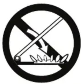
- The grill burner should only be used for grilling.
natural_image
Prohibition sign showing a crossed-out tool and flame symbol (no text)-
ATTENTION: The glass door may crack when it is heated. Close all burners before closing the glass door. Before closing the glass door, wait until the hob surface gets cooled.
-
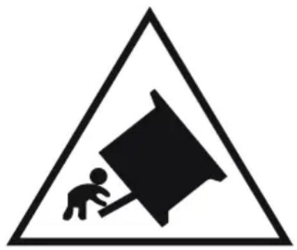
TIPPING HAZARD: The following balancing setting must be set up to prevent the tipping of the appliance. Please see the instructions for installation (See chain connection).
natural_image
Warning sign depicting a person pushing a large object inside a triangle (no text or symbols)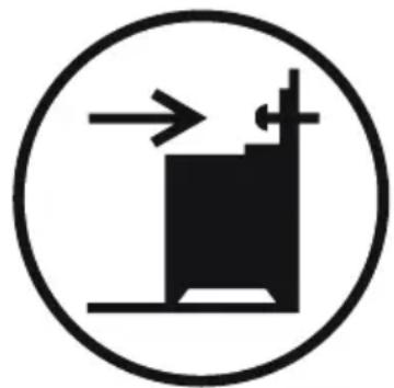
natural_image
Simple black-and-white diagram of a vertical structure with arrows indicating direction, enclosed in a circle (no text or symbols)| * Closing The Glass Door (Optional) | ||
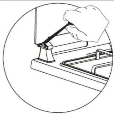
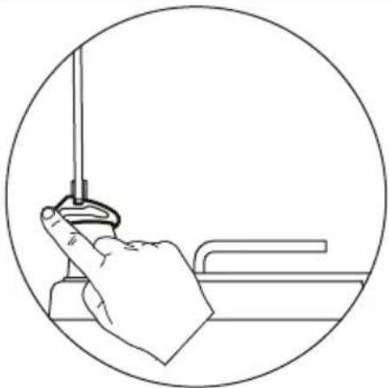
| The glass door can be closed in 3 ways;1. As shown in figure 1, the glass door can be closed by pressing the latch located on the plastic clip with a finger.2. As shown in figure 2, the glass door can be closed by pressing the plastic clip with a finger.3. As shown in figure 3, the glass door can be closed by pressing the plastic clip with the help of a spoon. | ||
 | 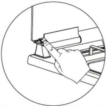 Figure 2 Figure 3Figure 1 Figure 2 Figure 3Figure 1 | 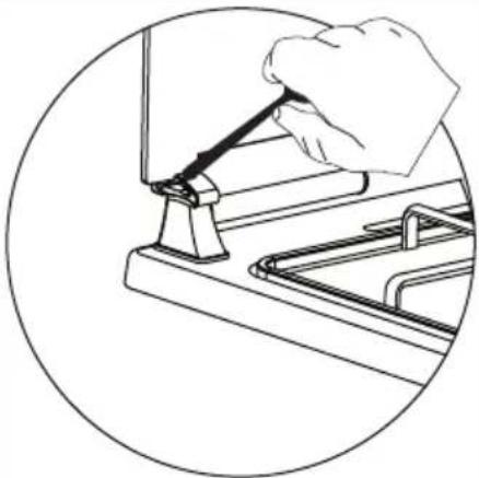 |
| RISK OF INJURY: If the glass door is closed in hard way, the glass may break and cause injury. The glass door must be supported by hand when closing in order to prevent hard closings.ATTENTION: The glass door may crack when it is heated. Close all burners before closing the glass door. Before closing the glass door, wait until the hob surface gets cooled. | ||
Electrical Safety
- WARNING: Cut off all supply circuit connections before accessing the terminals.
- WARNING: If the surface is cracked, turn off the appliance to avoid risk of electric shock.
- Plug the product in a grounded socket protected by a fuse conforming to the values specified in the technical specifications chart.
- Have an authorised electrician set grounding equipment. Our company shall not be responsible for the damages that shall be incurred due to using the product without grounding according to local regulations.
- The circuit breaker switches of the oven shall be placed so that end user can reach them when the oven is installed.
- Do not touch the plug with wet hands. Do not pull the cord to plug off, always hold the plug.
-
If you use an electrical appliance, e.g. a hand mixer, near the oven, make sure that the power cord does not get caught in the oven door. The insulation of the cable can be damaged.
-
Never wash the product by spraying or pouring water on it! There is a risk of electrocution.
- Do not use cut or damaged cords or extension cords other than the original cord.
- Make sure that there is no liquid or humidity in the outlet where the product plug is installed.
- The rear surface of the oven also heats up when the oven is operated. Electrical connections shall not touch the rear surface, otherwise the connections may be damaged.
- Do not tighten the connecting cables to the oven door and do not run them over hot surfaces. If the cord melts, this may cause the oven to short circuit and even a fire.
- Unplug the unit during installation, maintenance, cleaning and repair.
- Make sure the plug is inserted firmly into wall socket to avoid sparks.
-
With a steam oven, the water container must not be immersed in water or cleaned in the dishwasher. Otherwise, there is a risk of electric shock when the water container is placed in the steam oven.
-
Do not use steam cleaners for cleaning the product, otherwise electric shock may occur.
- User should not dislocate the resistance during cleaning. It may cause an electric shock.
- An omnipolar switch capable to disconnect power supply is required for installation. Disconnection from power supply shall be provided with a switch or an integrated fuse installed on fixed power supply according to building code.
- The product is equipped with a type "Y" cord cable.
- Fixed connections shall be connected to a power supply enabling omnipolar disconnection. For appliances with over voltage category below III, disconnection device shall be connected to fixed power supply according to wiring code.
- Cable fixing point shall be protected.
Gas Safety
- This appliance is not connected to burning products evacuation apparatus. This appliance must be connected and installed according to the installation regulations in force. Conditions regarding ventilation should be considered.
- When a gas cooking appliance is used; humidity, heat and burning products are generated in the room. First, make sure the kitchen is well ventilated when operating the appliance and maintain natural ventilation openings or install a mechanical ventilation equipment.
- After using the appliance heavily for an extended period of time, additional ventilation may be required. For example open a window or adjust a higher speed for mechanical ventilation, if any.
- This appliance must be installed in accordance with the current regulations and only in well-ventilated areas. Please read the instructions carefully before installing and using this appliance.
-
Before positioning the appliance, make sure local network conditions (Gas type and gas pressure) meet appliance requirements.
-
Appliance cannot be operated for longer than 15 seconds. If the burner is not on after 15 seconds, stop the mechanism and wait for at least one minute before trying to ignite the burner again.
- All kinds of operations to be performed on gas installation must be performed by authorized and competent people.
- If you have to use your product with a different gas type than the factory delivery, you have to apply to authorised service for the conversion.
- For proper operation, hood, gas pipe and clamp should be replaced periodically according to manufacturer recommendations and when required.
- Gas should burn well in gas products. Well burning gas can be understood from blue flame and continuous burning. If gas does not burn sufficiently, carbon monoxide (CO) can be generated. Carbon monoxide is a colourless, odourless and very toxic gas; even small amounts have lethal effect.
- Ask your local gas supplier about the phone numbers for emergencies related to gas and the measures to be taken if gas odour is detected.
THINGS TO DO WHEN GAS ODOUR IS DETECTED
- Do not use naked flame, and do not smoke.
- Do not operate any electrical switch (For example: lamp switch or doorbell).
- Do not use telephone or mobile phone.
- Open the doors and windows.
- Close all valves on the appliances that utilize gas and the gas counters.
- Call fire brigade from a telephone outside the home.
- Check all hoses and their connections against leaks. If you still smell gas, leave the house and warn your neighbours.
- Do not enter into the house until authorities clarify it is safe.
INTENDED USE
- This product is designed for home use. Commercial use of the appliance is not permitted.
- This product may only be used for cooking purposes. It shall not be used for other purposes like heating a room.
- This product shall not be used to heat plates under the grill, drying clothes or towels by hanging them on the handle or for heating purposes.
- The manufacturer assumes no responsibility for any damage due to misuse or mishandling.
- Oven part of the unit may be used for thawing, roasting, frying and grilling food.
- Operational life of the product you have purchased is 10 years. This is the period for which the spare parts required for the operation of this product as defined is provided by the manufacturer.
POWER CONNECTION
This oven should be installed and connected correctly according to the manufacturer's instructions and by the authorised service.
WARNING: The electrical connections of the appliance should only be made with (Grounded) sockets with a grounding system that is laid in accordance with the rules.
Contact an authorised electrician if there is no suitable socket for the grounded system where your appliance will be placed. The manufacturer is absolutely not responsible for the damages caused by the ungrounded sockets connected to the appliance.
Your device complies with protection class I. Your oven's plug is grounded; please make sure that the outlet you shall connect the plug is grounded. The plug shall be placed so that it can be accessed after installation.
Your appliance is manufactured for a 220-240 V N AC / 380-415 V 3N AC 50-60 Hz. electrical supply and requires a fuse of 16 or 32 A. If your power network does not provide these specifications, contact an electrician or an authorised service.
The circuit breaker switches of the appliance shall be placed so that end user can reach them when the oven is installed.
WARNING: When making the connection, take safety precautions against turning on power unintentionally.
WARNING: The power supply cable should not touch the hot parts of the appliance.
WARNING: If the power supply cord is damaged, this cord shall be replaced by the manufacturer or its service agent or an equally qualified personnel to prevent a hazardous situation.
Wiring Diagram
WARNING: The electrical connection of the product must be done by an authorised and certified personnel. Manufacturer shall not be held responsible for damages that may arise due to the operations performed by unauthorised persons.
WARNING: Have an authorised electrician set grounding equipment. Manufacturing company will not be responsible for the damages that may occur due to using the product without grounding according to local regulations.
RISK OF ELECTROCUTION: Before conducting any operation on the electrical wiring, remove the electrical connection of the appliance.
Wiring Diagram
Make the electrical connection of your oven according to the appropriate wiring diagram.
220-240 V ~ 50-60 Hz.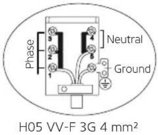 | 380-415 V 3N ~ 50-60 Hz.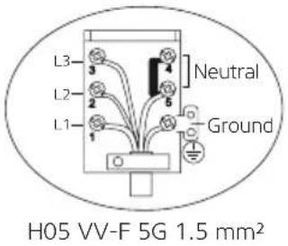 | 220-240 V ~ 50-60 Hz.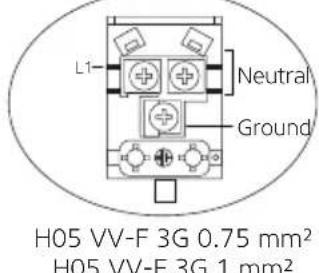 |
380-415 V 2N ~ 50-60 Hz.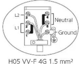 | 220-240 V ~ 50-60 Hz.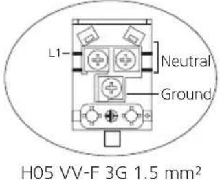 | 220-240 V ~ 50-60 Hz.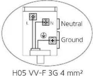 |
Power supplies vary according to the electrical power that is used by the appliance. You can acquire the electrical power of the appliance by looking at the type label on the appliance's rear hood. The following table should be considered during the power supply change.
| Power Range Feeding Cord Type And Size | |
| 0-1379 W H05 VV-F 3G 0.75 mm2 | |
| 1380-2299 W H05VV-F 3G 1.0 mm2 | |
| 2300-3679 W H05VV-F 3G 1.5 mm2 | |
| 3680-7359 W H05VV-F 4G 1.5 mm2 | |
| 3680-......W H05VV-F 5G 1.5 mm2 | |
| 5750-7359 W H05VV-F 3G 4 mm2 |
GAS CONNECTION
RISK OF EXPLOSION: Before starting any work related with gas installation, turn off gas supply. Risk of explosion.
WARNING: All kinds of work to be performed on gas equipment and systems should be carried out by authorised and qualified persons. Manufacturer shall not be held responsible for damages that may arise due to the operations performed by unauthorised persons.
WARNING: Check if the appliance settings are compatible with the local distribution conditions (Gas type and gas pressure) before placing the appliance.
The product does not have an exhaust. For this reason, this product should be installed according to installation regulations in force. Conditions regarding ventilation should be considered.
Use the product on a flat surface and in a well-ventilated environment.
Gas Hose Crossing Path
Make sure that the appliance's gas pipe and power cable do not pass by the hot surfaces.
Connect your appliance to the gas mains cock in the shortest way and without any leakage.
WARNING: Hose types must comply with EN 1762 standard for LPG and EN 14800 standard for NG.
WARNING: The hose which is used for safety should be at least 50 cm and at most 125 cm.
WARNING: Do not move a gas connected appliance. Any force may cause gas leakage as it may loosen the hose.
| LPG Connection | |
| Attach the metal clamp to the hose coming from the LPG cylinder. Install one end of the hose by pushing it all the way to the hose inlet fitting on the back of the appliance by heating it in boiling water. Tighten with a screwdriver by bringing the clamp to the end of the hose. Check for gas leakage and complete the connection. The hose and gasket inlet fitting required for connection is as follows. | |
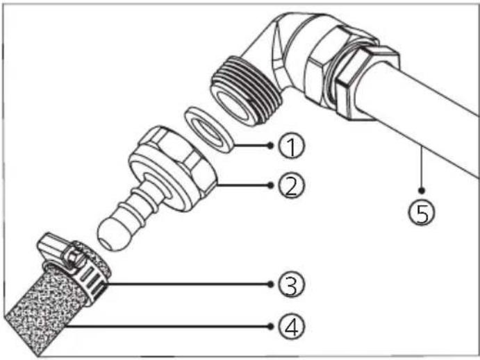 | 1. Gasket |
| 2. Hose entry fitting | |
| 3. Metal clamp | |
| 4. LPG connection hose | |
| 5. Main gas pipe | |
| WARNING: Do not move a gas connected appli-ance. Any force may cause gas leakage as it may loosen the hose. | |
| Natural Gas Connection | |
| Turn the nut to attach the hose to the main gas pipe. Check for gas leakage and complete the connection. The hose and connection fitting required for connection is as follows. | |
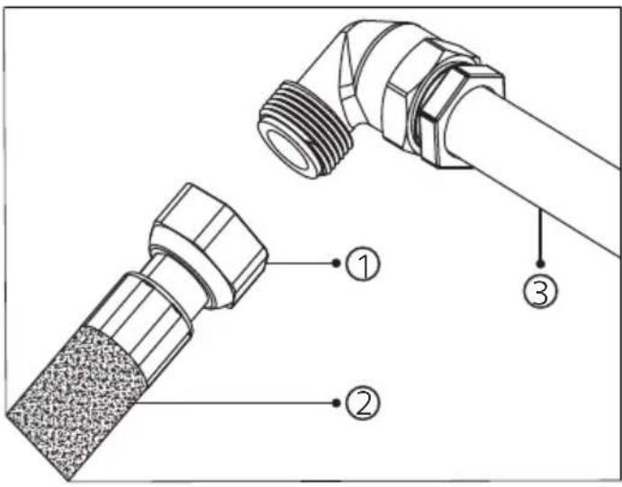 | 1. Nut |
| 2. Natural gas connection hose | |
| 3. Main gas pipe | |
| WARNING: Do not move a gas connected appli-ance. Any force may cause gas leakage as it may loosen the hose. | |
| Sealing Check | |
| Ensure that the knobs on the control panel are closed and the hood is open for sealing and gasket safety control.Apply soap foam to the connection points. There will be foaming here if there is a leak/leakage. | |
| WARNING: Never use any lighters, matches, lit cigarettes, or similar flammable materials when checking for gas leakage. | |
| Room Ventilation | |
| Oxygen required for combustion is taken from the room air and gases produced are returned directly to the room.A good room ventilation is essential for the safe operation of your product.If there are no windows or doors to be used for room ventilation, additional ventilation should be installed. However, if the room has a door that opens directly to the outside, there is no need for additional ventilation systems. | |
| Room Size Ventilation Opening | |
| Less than 5 m3 min. 100 cm2 | |
| 5 m3 to 10 m3 min. 50 cm2 | |
| Greater than 10 m3 is not necessary | |
| In basement or cellar min. 65 cm2 | |
| Conversion From Natural Gas To LPG Or From LPG To Natural Gas | ||
| WARNING: Disconnect the product from gas and electricity. | ||
| RISK OF BURNS: If the product is hot, wait for it to cool down. | ||
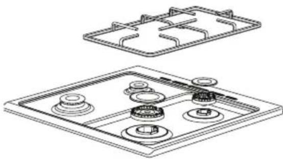
| To Replace The Injector;1. Lift the grate, burner cover and burner of the product so that the injector is visible (See figure 1).2. With the help of a screwdriver (7 mm) with the tip as shown in figure 2, remove the injector by turning it (See figure 3).3. Replace the injectors with suitable ones according to the values in the injector table and the type of gas to be used in the appliance. | ||
 | 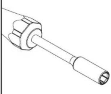 | 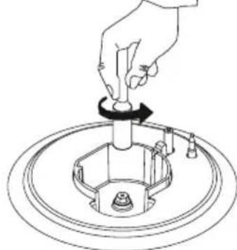 |
| Figure 1 Figure 2 Figure 3 | ||
| WARNING: Injector replacement should be done by an authorised service. | ||
Flame Output Speed Setting
After replacing the injectors, it is also necessary to adjust the gas taps to the new type of gas.
Before starting the operation, make sure that the appliance plug is plugged in, the gas supply is on and the burners are completely placed.
Note: Gas setting screw for the low flame position must be loosened when switching from LPG to natural gas. During switching from natural gas to LPG, it should be tightened.
- Put the cooker burners in a low position and pull out the cooker control knobs on the control panel (See figure 4).
- With the help of a proper size screwdriver, tighten/loosen the gas setting screw (See figure 5). This enables the flame in the low position to increase or decrease. Adjust the proper gas setting so that the flame length is at least 4 mm.
- For the final check, turn the flames of the cooker burners to the highest and lowest positions. In both cases, the flame must be ignited.
- Repeat these procedures for each burner of the cooker.
- After making the proper gas setting, install the control knobs in order to use the product.

natural_image
Line drawing of a mechanical assembly with multiple cylindrical components mounted on a bracket (no text or symbols)Figure 4 Figure 5
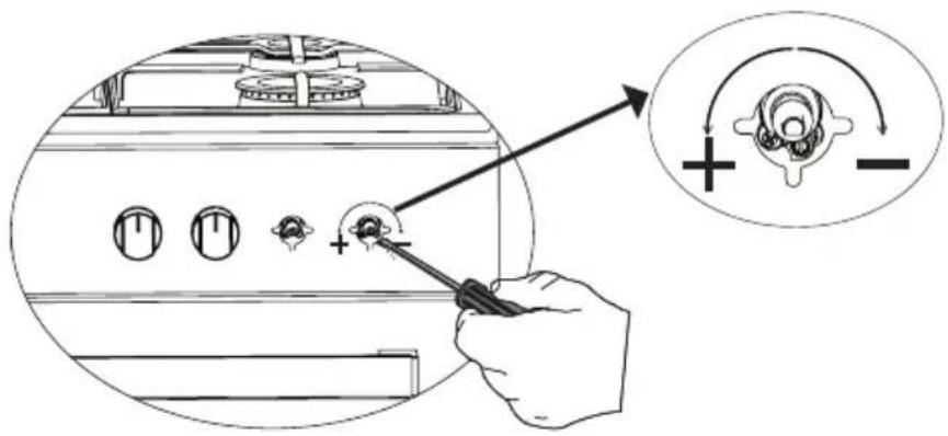
WARNING: Depending on the type of hob spout used in your product, the position of the gas setting screw may vary.
| [APPLIANCE INTRODUCTION (Optional) | ||||
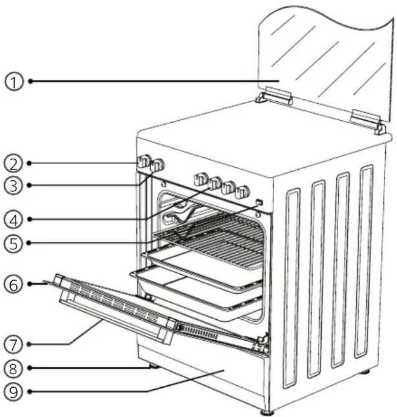 | Glass or metal door | |||
| Temperature adjustment knob(Thermostat) | ||||
| Cooking function knob | ||||
| Hob section control knobs | ||||
| Ignition knob | ||||
| Oven door | ||||
| Oven handle | ||||
| Plastic leg | ||||
| Lower cabinet door | ||||
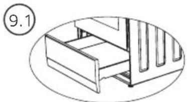 | 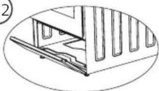 | 9.1. Drawer | ||
| 9.2.Openable door | ||||
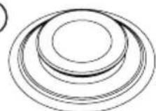 | 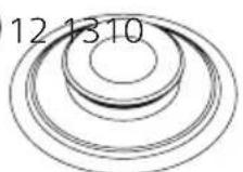 |  | 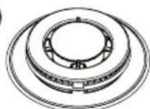 | |
| Large burner | Middle burner | Small burner | Wok burner | |
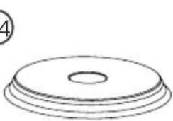 | 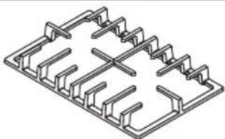 | 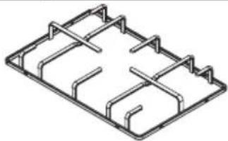 | ||
| Electric heater (Hot plate) * Hob grills | ||||
| Note: The appliance image above is only provided for illustration purposes. The image of the appli-ance may vary depending on the option. Only consider your appliance. | ||||
| * ACCESSORIES (Optional) | ||||
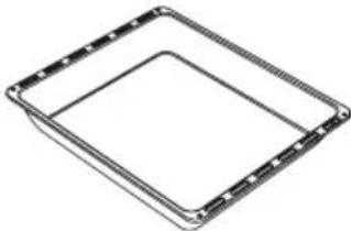 | Deep trayIt is used for pastries, large roasts, stews. For cakes, frozen dishes and meat dishes; you may also use it as a container for collecting grease in case of roasting directly on the grill. | |||
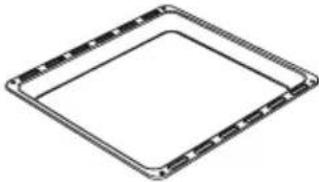 | Standard tray / Glass trayIt is used for pastry (Cookies, biscuits, etc.), and frozen foods. | |||
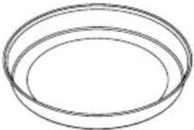 | Circular trayIt is used for pastry and frozen foods. | |||
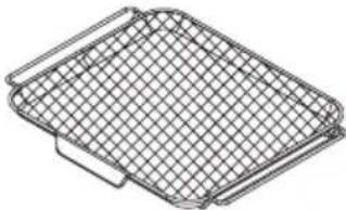 | Drying / Air fryer trayDrying function and air fryer is used for foods to be cooked. Place the standard tray under the air fryer tray to collect the oil dripping during cooking. Add some water on the standard tray for easy cleaning. | |||
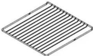 | Wire grillIt is used for roasting or to place the frozen food, or food to be fried or roasted on the desired rack. | |||
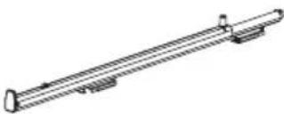 | Telescopic railThanks to telescopic rails, trays or wire shelves may be easily attached and removed. | |||
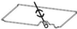 | Chicken roastIt is used for foods intended to be cooked by being rotated. | |||
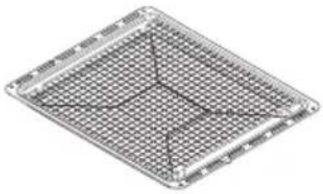 | Grilled baconPlace the bacon on the grill tray. Foods that may stick during cooking are cooked on the bacon grill. This prevents food from contacting the tray and sticking into it. | |||
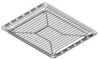 | Wire grill inside trayPlace the wire grill inside tray on the tray. Food that may stick while being cooked, like steak, are placed on the wire grill inside the tray. This prevents food from contacting the tray and sticking into it. | |||
 | Splash back (Heat protection sheet)It prevents the contact of the temperature of the oven with the wall. | |||
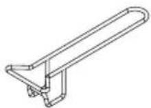 | Tray handleIt is used to hold hot trays. | |||
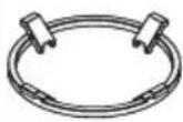
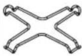 | 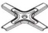 | Coffee adapter (Coffee pot)Can be used for coffee pots. Ensure that the legs of the coffee adapter are completely seated on the cooker grate and placed on the center of the hob. | ||
 | 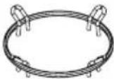 | Wok burner adapterCan be used for wok pans. When flat-bottomed containers are used in the wok burner, the wok burner adapter should not be used. Wok burner adapter is suitable for convex containers. | ||
| *Telescopic Rails | |
| Telescopic rails allow you to pull tray and internal grill easily. | |
 | |
 | |
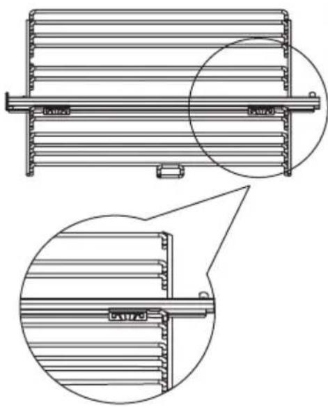 | Telescopic rails, which are provided to you as an accessory, can be mounted on the side wire racks easily with two pieces of holding clips. Since there are right and left rails, make sure that you know which rail you shall install on which side. Check the right (R) and left (L) signs on the rails. |
| Our installation recommendation is that you should take the side wire racks completely out of the oven and install the telescopic rails on the side wire racks on a flat surface. Install the telescopic rail on the upper one among the two racks. The rails can be easily mounted and demounted. After adjusting the positions of right and left telescopic rails, press on them until they are inserted into the side wire racks. | |
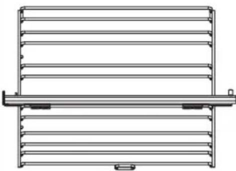 | Check whether the rails are seated completely or not by looking behind the wire rack. |
| After installing the telescopic rails, mount the wire racks into the oven again. Do not use the wire grill just below the rack on which the telescopic rail is fixed. | |
| Placing The Tray Or Wire Grill On The Telescopic Rail Appropriately | |
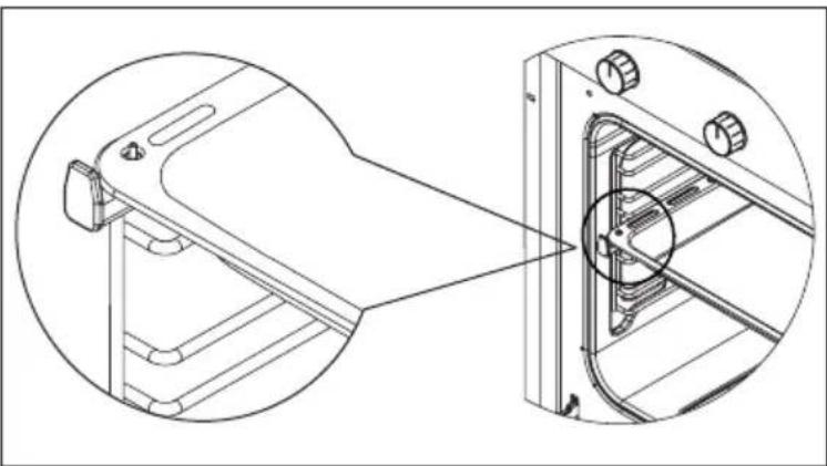 | Thanks to the telescopic shelves, trays or wire grill may be easily inserted and removed. When using the tray or wire grill with the telescopic rail, make sure that the pins on the back of the telescopic rail rest on the back of the tray or wire grill. |
| Using The Wire Grill | |
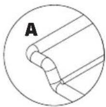  | It is important to place the wire grill and tray properly on the wire racks and correctly place the grill and/or tray on the rack.Correct placement is shown in the adjacent figure.Place the grill or tray between two rails and make sure it is balanced before putting food on it.Note: Do not use the wire grill just below the rack on which the telescopic rail is fixed. |
| TECHNICAL SPECIFICATIONS | ||||||
| Features 50x55 50x60 56x57 60x60 | ||||||
| External width 500 mm 500 mm 560 mm 600 mm | ||||||
| External depth 565 mm 630 mm 570 mm 630 mm | ||||||
| External height 855 mm 855 mm 855 mm 855 mm | ||||||
| Light power 15-25 W | ||||||
| Lower heating element 1000 W 1000 W 1000 W | 60 Litres 80 Litres | |||||
| 1200 W 1200 W | ||||||
| Upper heating element | 800 W | 800 W | 800 W | 1000 W | 1200 W | |
| Turbo heater | ---- 1800 W 1800 W 2200 W 1800 W | |||||
| Grill | 1500 W 1500 W 1500 W 2000 W | Small grill | Large grill | |||
| 1200 W | 2400 W | |||||
| Supply voltage | 220-240 V AC / 380-415 V AC 50-60 Hz. | |||||
| * 80 mm electric heater (Hot plate) | 450 W | |||||
| * 145 mm electric heater (Hot plate) | 1000 W | |||||
| * 180 mm electric heater (Hot plate) | 1500 W | |||||
| * 145 mm quick electric heater (Hot plate) | 1500 W | |||||
| * 180 mm quick electric heater (Hot plate) | 2000 W | |||||
| * 220 mm electric heater (Hot plate) | 2000 W | |||||
WARNING: Technical specification and injector table should be taken into consideration in the change to be made by the authorised service. Manufacturer may not be held responsible for any problems rising because of any faulty modification.
WARNING: In order to increase the product quality, the technical specifications may be changed without prior notice.
WARNING: The values provided with the appliance or its accompanying documents are laboratory readings in accordance with the respective standards. These values may differ depending on the use and ambient conditions.
| Injector Table | |||||||||
| By Gas Type Burner Specifications | G20,20 mbar G25,25 mbar | G20,25 mbar G20,13 mbar | |||||||
| Natural gas Natural gas | Natural gas Natural gas | ||||||||
| Wok Burner (4,5) | Injector | 1,60 m | mm 1,60 mm | mm 1,35 mm | mm 1,84 mm | ||||
| Gas flow | 0,421 m3/h | 0,487 m3/h | 0,418 m3/h | 0,424 m3/h | |||||
| Power | 4,50 | kW | 4,50 | kW | 4,50 | kW | 4,50 | kW | |
| Wok Burner (3,5) | Injector | 1,40 m | mm 1,40 mm | mm 1,28 mm | mm 1,60 mm | ||||
| Gas flow | 0,327 m3/h | 0,379 m3/h | 0,326 m3/h | 0,330 m3/h | |||||
| Power | 3,50 | kW | 3,50 | kW | 3,50 | kW | 3,50 | kW | |
| Wok Burner (2,5) | Injector | 1,15 m | mm 1,15 mm | mm 1,06 mm | mm 1,35 mm | ||||
| Gas flow | 0,234 m3/h | 0,270 m3/h | 0,233 m3/h | 0,235 m3/h | |||||
| Power | 2,50 | kW | 2,50 | kW | 2,50 | kW | 2,50 | kW | |
| Wok Burner (2,4) | Injector | 1,15 m | mm 1,15 mm | mm 1,10 mm | - mm | ||||
| Gas flow | 0,224 m3/h | 0,260 m3/h | 0,223 m3/h | - m3/h | |||||
| Power | 2,40 | kW | 2,40 | kW | 2,40 | kW | - | kW | |
| Wok Burner (1,9) | Injector | 1,05 mm | mm 1,05 mm | mm 1,05 mm | - mm | ||||
| Gas flow | 0,178 m3/h | 0,206 m3/h | 0,177 m3/h | - m3/h | |||||
| Power | 1,90 | kW | 1,90 | kW | 1,90 | kW | - | kW | |
| Large Burner | Injector | 1,15 mm | mm 1,15 mm | mm 1,10 mm | mm 1,45 mm | ||||
| Gas flow | 0,271 m3/h | 0,314 m3/h | 0,270 m3/h | 0,273 m3/h | |||||
| Power | 2,90 | kW | 2,90 | kW | 2,90 | kW | 2,90 | kW | |
| Medium Burner | Injector | 0,97 mm | mm 0,97 mm | mm 0,92 mm | mm 1,10 mm | ||||
| Gas flow | 0,159 m3/h | 0,184 m3/h | 0,158 m3/h | 0,160 m3/h | |||||
| Power | 1,70 | kW | 1,70 | kW | 1,70 | kW | 1,70 | kW | |
| Small Burner | Injector | 0,72 mm | mm 0,72 mm | mm 0,70 mm | mm 0,85 mm | ||||
| Gas flow | 0,096 m3/h | 0,103 m3/h | 0,088 m3/h | 0,090 m3/h | |||||
| Power | 0,95 | kW | 0,95 | kW | 0,95 | kW | 0,95 | kW | |
| Grill Burner | Injector | 1,00 mm | mm 1,00 mm | mm 0,92 mm | mm 1,10 mm | ||||
| Gas flow | 0,187 m3/h | 0,216 m3/h | 0,186 m3/h | 0,196 m3/h | |||||
| Power | 2,00 | kW | 2,00 | kW | 2,00 | kW | 2,00 | kW | |
| Oven Burner | Injector | 1,10 mm | mm 1,10 mm | mm 1,00 mm | mm 1,20 mm | ||||
| Gas flow | 0,234 m3/h | 0,270 m3/h | 0,232 m3/h | 0,235 m3/h | |||||
| Power | 2,50 | kW | 2,50 | kW | 2,50 | kW | 2,50 | kW | |
| By Gas Type Burner Specifications | G30,28-30 mbar G31,37 mbar G30,50 mbar G30,37 mbar | ||||||||
| LPG LPG LPG LPG | |||||||||
| WokBurner (4,5) | Injector | 1,07 mm 1,07 mm 0,92 mm 1,00 mm | |||||||
| Gas flow | 259 g/h 338 g/h 255 g/h 257 g/h | ||||||||
| Power | 4,50 kW 4,50 kW 4,50 kW 4,50 kW | ||||||||
| WokBurner (3,5) | Injector | 0,96 mm 0,96 mm 0,76 mm 0,96 mm | |||||||
| Gas flow | 203 g/h 197 g/h 197 g/h 201 g/h | ||||||||
| Power | 3,50 kW 3,50 kW 3,50 kW 3,50 kW | ||||||||
| WokBurner (2,5) | Injector | 0,82 mm 0,82 mm 0,73 mm 0,78 mm | |||||||
| Gas Flow | 145 g/h 189 g/h 141 g/h 143 g/h | ||||||||
| Power | 2,50 kW 2,50 kW 2,50 kW 2,50 kW | ||||||||
| WokBurner (1,9) | Injector | 0,68 mm 0,68 mm 0,60 mm 0,65 mm | |||||||
| Gas flow | 110 g/h 143 g/h 108 g/h 110 g/h | ||||||||
| Power | 1,90 kW 1,90 kW 1,90 kW 1,90 kW | ||||||||
| LargeBurner | Injector | 0,85 mm 0,85 mm 0,75 mm 0,85 mm | |||||||
| Gas flow | 168 g/h 163 g/h 163 g/h 166 g/h | ||||||||
| Power | 2,90 kW 2,90 kW 2,90 kW 2,90 kW | ||||||||
| MediumBurner | Injector | 0,65 mm 0,65 mm 0,60 mm 0,65 mm | |||||||
| Gas flow | 98 g/h 96 g/h 96 g/h 97 g/h | ||||||||
| Power | 1,70 kW 1,70 kW 1,70 kW 1,70 kW | ||||||||
| SmallBurner | Injector | 0,50 mm 0,50 mm 0,43 mm 0,50 mm | |||||||
| Gas flow | 55 g/h 53 g/h 55 g/h 54 g/h | ||||||||
| Power | 0,95 kW 0,95 kW 0,95 kW 0,95 kW | ||||||||
| GrillBurner | Injector | 0,70 mm 0,70 mm 0,60 mm 0,65 mm | |||||||
| Gas flow | 116 g/h 113 g/h 114 g/h 114 g/h | ||||||||
| Power | 2,00 kW 2,00 kW 2,00 kW 2,00 kW | ||||||||
| OvenBurner | Injector | 0,75 mm 0,75 mm 0,65 mm 0,70 mm | |||||||
| Gas flow | 145 g/h 141 g/h 141 g/h 143 g/h | ||||||||
| Power | 2,50 kW 2,50 kW 2,50 kW 2,50 kW | ||||||||
Note: The diameter values written on the injector are indicated without commas. For example; the diameter, which is 1,70 mm, is indicated on the injector as 170.
SETTING UP THE APPLIANCE
Check if the electrical and gas installation is proper to bring the appliance in operating condition. If electricity and gas installation is not suitable, call a certified plumber to arrange the utilities as necessary.
WARNING: Manufacturer shall not be held responsible for damages caused by operations performed by unauthorised persons.
WARNING: It is customer's responsibility to prepare the location the product shall be placed on and also to have the electrical installation prepared.
WARNING: The rules specified in the local standards related to electricity and gas should be followed when installing the product.
WARNING: Check for any damage on the appliance before installing it. Do not have the product installed if it is damaged. Damaged products cause a risk for your safety.
WARNING: Keep the ventilation channels open.
WARNING: Correct personal protection equipment should be worn and applicable safety regulations should be followed during installation.
WARNING: The product should be positioned to avoid any air flow that could impact ignition and to prevent the accumulation of unburned gas.
WARNING: Appliances working with LPG should not be mounted under the floor level.
Right Place For Installation
Appliance feet should not stay on soft surfaces such as carpets. The product should be placed on a hard surface. The kitchen floor shall be durable to carry the unit weight and any other kitchenware that may be used on the oven.
Appliance should be used with a clearance of minimum 400 mm over the upper hob surfaces, and 50 mm from side surfaces inside a kitchen furniture.
The appliance is suitable for use on both side walls, without any support, or without being installed in a cabinet. If a hood or aspirator will be installed above the appliance, follow the instructions of the manufacturer for height of mounting (Min. 650 mm).
The product can be placed side by side with kitchen walls, kitchen furniture, or any size of product behind or on one side. The kitchen furniture in the immediate vicinity of the product should be the same size or smaller than the product.
It is necessary to have at least a 2 cm gap between the product and the wall for air circulation.
Correct Installation
For accurate installation, please follow the dimensions given in the image below.
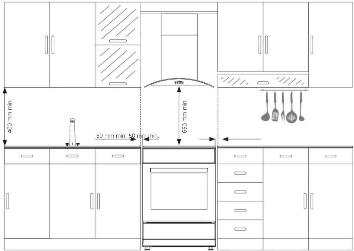
WARNING: The kitchen furniture near the appliance must be heat resistant (Minimum 100 °C).
WARNING: Do not install the appliance beside refrigerators or coolers. Heat radiated by the appliance increases the energy consumption of cooling devices.
WARNING: Do not use the door and/or handle to carry or move the appliance.
\* Chain Connection
To ensure safe use of the appliance, it must be secured before use in order to prevent it from tipping over. Fasten the hook screw supplied with your appliance firmly to the kitchen wall with the dowel. Ensure that the hook is firmly fixed to the wall. Then insert the safety chain into the hook screw.
The safety chain should be as short as possible to prevent the tipping of the oven to the side and forward.
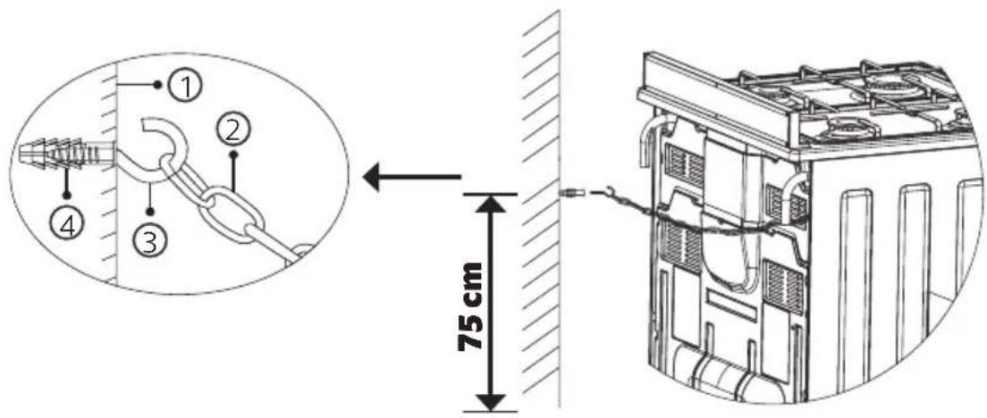
- Kitchen wall
- Safety chain
- Hook screw
- Dowel
\* Installation Of The Leg Adapter
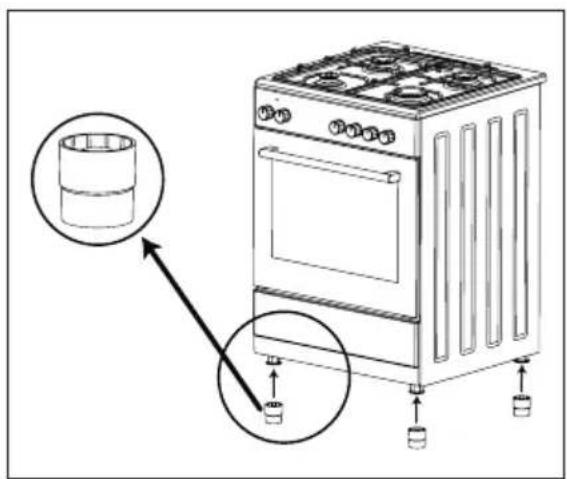
As shown in the figure, the installation of the leg adapters is done by threading them on the oven legs.
Note: Leg adapters increase the height of the oven.
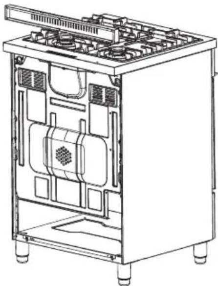
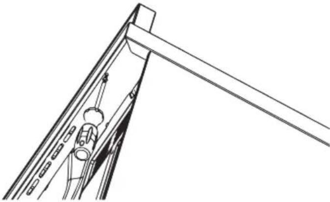
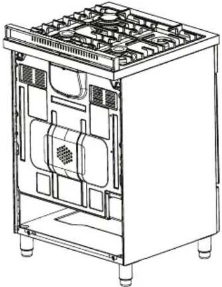
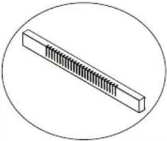
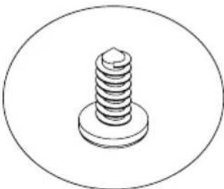
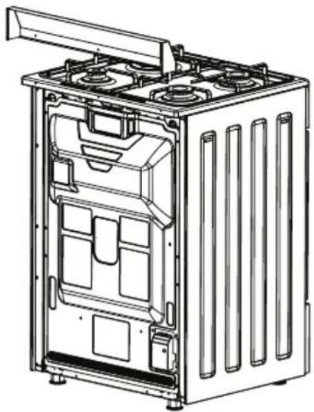
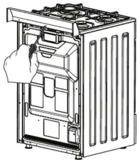
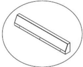
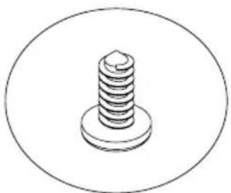
| *60x60 Professional Oven Splash Back (Heat Protection Sheet) Installation | ||
 |  | |
 |  | 1 |
 | 2 | |
| Align the splash back (Heat protection sheet) installation slots (1) with the holes on the table. | Then tighten the screws (2) into the splash back (heat protection sheet) installation holes (1) with the help of a suitable screwdriver. | |
| By carrying out the process in reverse sequence, you can remove the splash back (Heat protection sheet). | ||
| * 56x57 Oven Splash Back (Heat Protection Sheet) Installation | ||
 |  | |
 |  | |
| 1 | 2 | |
| Align the splash back (Heat protection sheet) installation slots (1) with the holes on the table. | Then tighten the screws (2) into the splash back (heat protection sheet) installation holes (1) with the help of a suitable screwdriver. | |
| By carrying out the process in reverse sequence, you can remove the splash back (Heat protection sheet). | ||
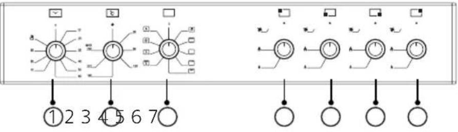
| CONTROL PANEL | ||
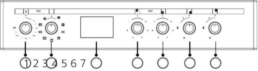
| For Electric Oven | ||
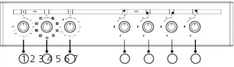 | 1. Temperature adjustment knob (Thermostat) | |
| 2. Cooking function knob | ||
| *3. Mechanical timer | ||
| 4. Rear left gas burner | ||
 | 5. Front left gas burner | |
| 6. Front right gas burner | ||
| 7. Rear right gas burner | ||
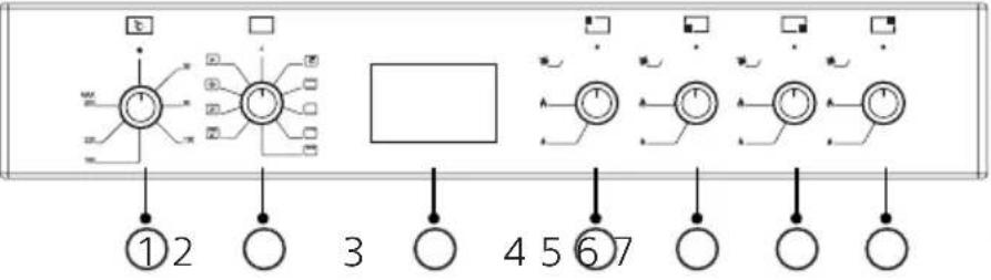
 | 1. Temperature adjustment knob (Thermostat) | |
| 2. Cooking function knob | ||
| *3. Digital timer | ||
| 4. Left rear electric cooking zone | ||
| 5. Left front electric cooking zone | ||
| 6. Front right gas burner | ||
| 7. Rear right gas burner | ||
 | 1. Temperature adjustment knob (Thermostat) | |
| 2. Cooking function knob | ||
| *3. Digital timer | ||
| 4. Rear left gas burner | ||
| 5. Front left gas burner | ||
| 6. Front right gas burner | ||
| 7. Rear right gas burner | ||
| WARNING: The control panel above is only for il-lustration purposes. Consider the control panel on your device. | ||
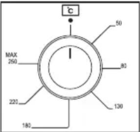
| Temperature Adjustment Knob (Thermostat) | ||
 | It is used for determining the cooking temperature of the dish to be cooked in the oven. After putting the meal in the oven you can set it to the desired temperature by turning the knob. Thermostat light goes out when the oven reaches the adjusted temperature. See the cooking table for the cooking temperatures of the different meals. | |
 | ||
| * Mechanical Timer Knob | ||
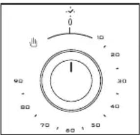 | It is used for determining the period for cooking in the oven. When adjusted time is expired, power to heaters is turned off and an audible warning signal is heard. The mechanical timer knob is rotated to set the cooking time to the desired time between 0-90 minutes. For cooking periods, see the cooking table. | |
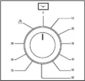 | ||
| Manual Cooking | ||
 | Note: In manual cooking, the cooking period is tracked by the user. | |
| * Control Panel Icons | ||
 |  | Auto ignition |
| For Gas Oven | |
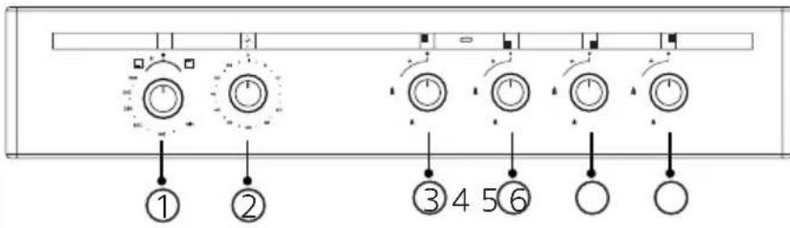 | 1. Cooking function knob and temperature adjustment knob (Thermostat) |
| *2. Mechanical timer | |
| 3. Rear left gas burner | |
| 4. Front left gas burner | |
| 5. Front right gas burner | |
| 6. Rear right gas burner | |
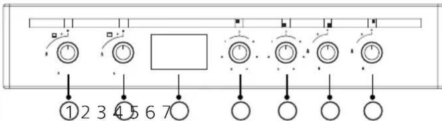 | 1. Lower burner cooking function knob |
| 2. Upper burner cooking function knob | |
| *3. Digital timer | |
| 4. Left rear electric cooking zone | |
| 5. Left front electric cooking zone | |
| 6. Front right gas burner | |
| 7. Rear right gas burner | |
| WARNING: The control panel above is only for il-lustration purposes. Consider the control panel on your device. | |
| WARNING: If there are two separate cooking function knobs on the control panel, controlling the lower and upper burners, both burners can be used at the same time. If there is a single cooking func-tion knob on the control panel, controlling the lower and upper burners, lower and upper burners can't be used at the same time. | |
| If the Oven (Lower)-Grill (Upper) Burner Is Controlled From One Knob | |
| Oven-Grill Burner Control And Temperature Adjustment Knob (Thermostat) | |
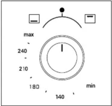 | It is used for determining the cooking temperature of the dish to be cooked in the oven. By turning the knob counter-clockwise after putting the food into the oven, you can start the oven burner and adjust the temperature. By turning the knob clockwise, you can operate the grill burner. See the cooking table for the cooking temperatures of the different meals. |
| If the Oven (Lower)-Grill (Upper) Burner Is Controlled From Double Knobs | |
| Oven Burner Control And Temperature Adjustment Knob (Thermostat) | |
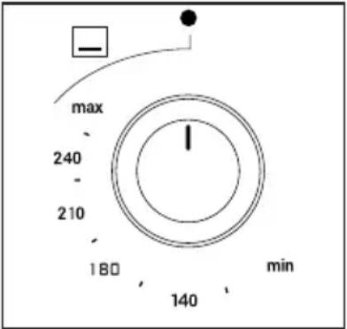 | It is used for determining the cooking temperature of the dish to be cooked in the oven. By turning the knob after putting the food into the oven, you can start the oven burner and adjust the temperature. See the cooking table for the cooking temperatures of the different meals. |
| Grill Burner Control Knob | ||
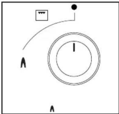 | It allows the grill to be controlled. By turning the knob, you can operate the grill. | |
| * Mechanical Timer Knob | ||
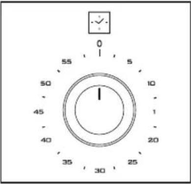 | It is used for determining the period for cooking in the oven. When adjusted time is expired, an audible warning signal is heard. The mechanical timer knob is rotated to set the cooking time to the desired time between 0-60 minutes. For cooking periods, see the cooking table. | |
| * Control Panel Icons | ||
 | 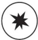 | Auto ignition |
 | Lamp on / off position | |
 | Light | |
| For Gas-Electric (Mixed) Oven | |
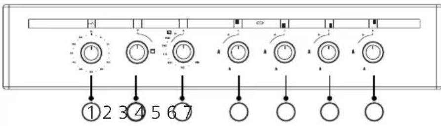 | *1. Mechanical timer |
| 2. Grill (Upper) | |
| 3. Oven (Lower) burner control and temperature adjustment knob (Thermostat) | |
| 4. Rear left gas burner | |
| 5. Front left gas burner | |
| 6. Front right gas burner | |
| 7. Rear right gas burner | |
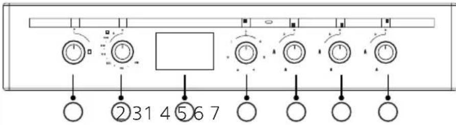 | 1. Grill (Upper) |
| 2. Oven (Lower) burner control and temperature adjustment knob (Thermostat) | |
| *3. Digital timer | |
| 4. Left rear electric cooking zone | |
| 5. Front left gas burner | |
| 6. Front right gas burner | |
| 7. Rear right gas burner | |
| WARNING: The control panel above is only for il-lustration purposes. Consider the control panel on your device. | |
| Oven Burner Control and Temperature Adjustment Knob (Thermostat) | |
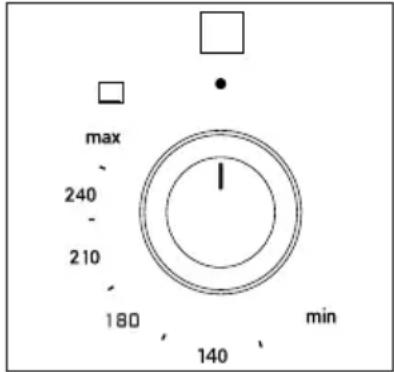 | The oven allows the burner to be controlled. It is also used for setting the cooking temperature of the dish to be cooked in the oven. By turning the knob after putting the food into the oven, you can start the oven burner and adjust the temperature. See the cooking table for the cooking temperatures of the different meals. |
| Grill Control Knob | |
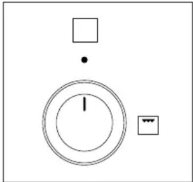 | It allows the grill to be controlled. By turning the knob, you can operate the grill. |
| * Mechanical Timer Knob | |
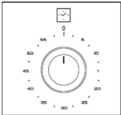 | It is used for determining the period for cooking in the oven. When adjusted time is expired, an audible warning signal is heard. The mechanical timer knob is rotated to set the cooking time to the desired time between 0-60 minutes. For cooking periods, see the cooking table. |
Initial Operation Of The Oven
After you have made the necessary connections of your oven according to the instructions, you shall need to do the following in the initial operation:
- Take out any labels or accessories that are affixed inside the oven. If there is a protective foil on the front of the appliance, remove it.
- Wipe the inside of the oven with a wet cloth to remove the dust and the remains of packaging. Inside of the oven shall be empty. Connect the appliance to the gas and electricity.
- Set the temperature adjustment knob to the highest temperature and operate the oven for 30 minutes with the door closed. A slight smoke and odour may arise in the meantime, this is a normal situation.
- After the oven has cooled down, wipe the inside of the oven with warm water with mild detergent and dry with a clean cloth. You can now use your oven.
- If your oven has a steam-assisted cooking function; remove the water container from the oven. Shake the water container well before using detergent.
Normal Operation Of The Oven
If The Oven Is An Electric Oven;
- To start cooking, use the temperature control knob to set the temperature at which you want to cook, depending on the type of food, and the cooking function control knob to set the desired cooking function.
- You can set the cooking time to a desired time by using mechanical timer knob in the models with a mechanical timer. When adjusted time is expired, power to heaters is turned off and an audible warning signal is heard.
- In the models with digital timer; when the cooking time has expired according to the information entered, the timer turns off the heaters and gives an audible signal.
If The Oven Is A Gas, Gas-Electric (Mixed) Oven;
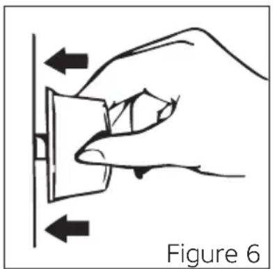
- To use the burner of your preference, first press the knob in the direction of the arrow and wait 5 seconds for air to escape from the pipes (See figure 6).
In Models With Manual Ignition; you can ignite the burner of your preference with an igniter (Match, lighter) by rotating the knob (See figure 7).
* In Models With (Auto) Ignition With A Knob; you can ignite the burner of your preference by pressing the knob in the direction of the arrow (See figure 6) and rotating the knob (See figure 7).
* In Button Ignited Models; first, press the button on the control panel (See figure 8). Then, by pressing your preferred burner knob in the direction of the arrow, you can ignite the burner (See figure 6).
natural_image
Hand pressing a button on a wall, labeled Figure 6 (no text or symbols on the diagram itself)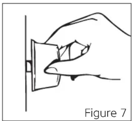
natural_image
Line drawing of a hand holding a small object against a vertical line, labeled 'Figure 7' (no text or symbols on the object itself)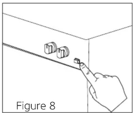
natural_image
Line drawing of a hand pointing at three small objects on a wall, labeled 'Figure 8' (no text or symbols on the diagram itself)WARNING: The ignition takes place by means of electricity in models with (Automatic) ignition with a knob. Therefore, make sure that the product is electrically connected before using the product.
RISK OF EXPLOSION AND BURNING: When the
burner is ignited, press and hold the knob for a maximum of 15 seconds for the flame checking system to operate. Holding down the knob for more time creates a risk of explosion and burning, as this will lead to the accumulation of gas. If there is no ignition, wait at least one minute with the oven door open. Then try to carry out ignition again.
- After the ignition is complete, you can start the cooking process.
- You can set the cooking time to a desired time by using knob in the models with a mechanical timer. When adjusted time is expired, power to heaters is turned off and an audible warning signal is heard.
- The timer gives an audible signal when the cooking time is up in line with the entered information in the models with a digital timer.
WARNING: In products with double knob control type; the upper burner should be started 15-20 minutes after the lower burner is started.
\* COOLING FAN
During operation of the oven, the cooling fan shall move excess steam out and prevent the appliance from overheating. This is necessary for ensuring your appliance to work well and to cook well.
The cooling fan continues to operate after cooking is finished. After cooling is complete, the fan shall automatically turn off.
Using The Grill
- When you place the grill on the top rack, the food on the grill shall not touch the grill.
- You can preheat for 5 minutes while grilling. If necessary, you may turn the food upside down.
- Food shall be in the center of the grill to provide maximum air flow through the oven.
To Turn On The Grill;
- Place the function knob over the grill symbol.
- Then, set it to the desired grill temperature.
To Turn Off The Grill;
Set the function knob to the off position.
WARNING: Keep the oven door closed when grilling (Electric grill with thermostat).
WARNING: Keep the oven door open while grilling (Gas and electric grill without thermostat).
| *Use Of Panel Protection Sheet | ||
| Panel protection plate is designed to protect the control panel and knobs when the oven is in grill mode and the oven door is open. When the oven is in grill mode, the panel protection plate (See figure 9) should be used to prevent heat damage to the control panel and knobs.Open the front glass door of the oven (See figure 10). Place the panel protection sheet and gently close the door and fix the panel protection plate (See figure 11). | ||
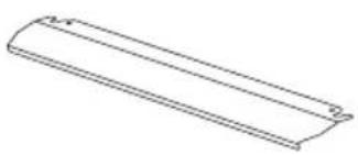 | 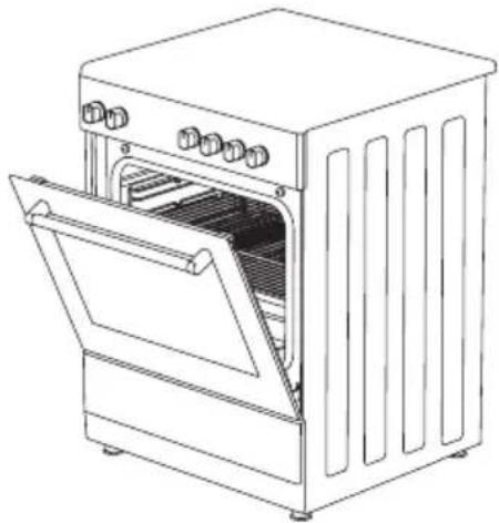 | 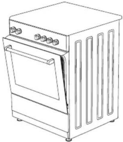 |
| Figure 9 Figure | 10 Figure 11 | |
| WARNING: The panel protection sheet is suitable for use with the door open. | ||
| * Use For Chicken Roasting | ||
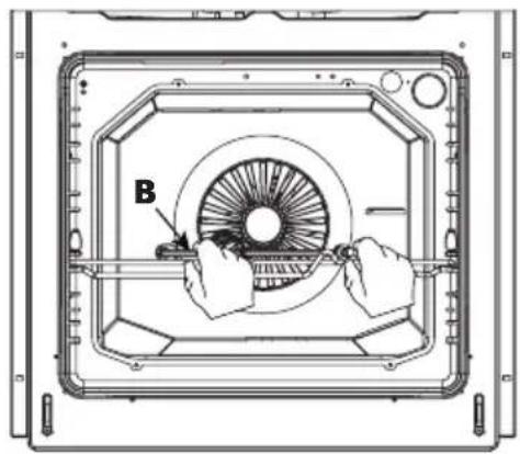
| WARNING: Remember to remove the plastic handle from the skewer by rotating it before closing the oven's door. | ||
| Skewer the fowl as a whole. In order to grill a fowl healthily, center and fix the fowl on the skewer (b) by the fixing hooks located on the both sides of the skewer (b). Place the skewer (b) on the rotisserie wire (a) and put it in the oven and make sure that the end of the skewer (b) is placed in the rotisserie engine chamber. | ||
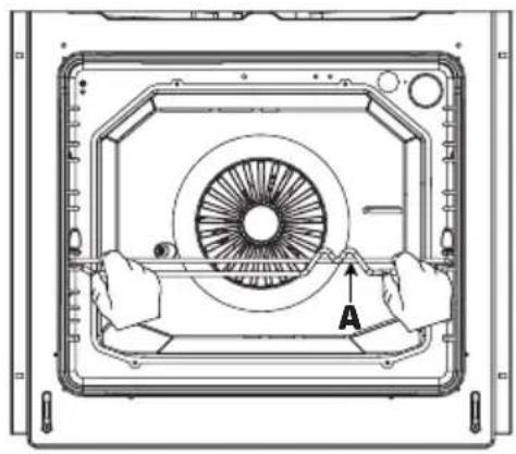 | 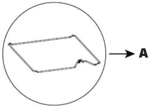 | |
 | 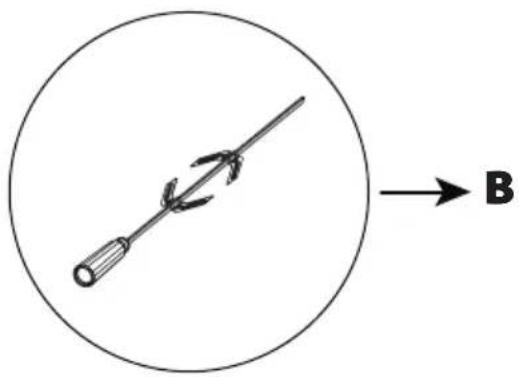 | |
| After closing the door, set the oven to the grill (☐) position and bring the thermostat temperature up to the maximum temperature level using the temperature setting button. In order to collect spilled oil during cooking, place the tray on the base. Add some water on the tray for easy cleaning. | ||
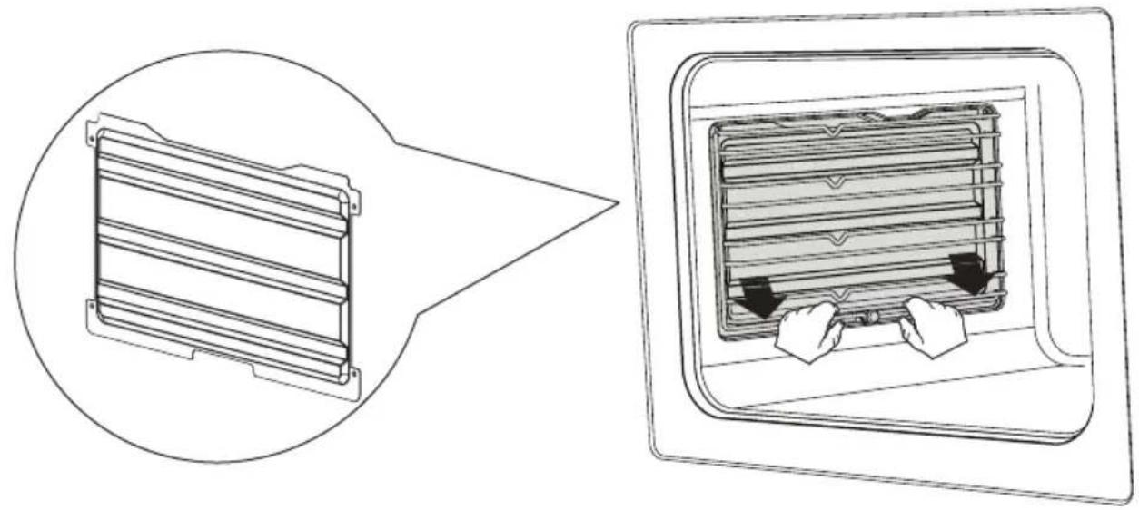
\* CATALYTIC PANEL
It is located behind the wire racks of the oven, at the right and left walls of oven cavity. Catalytic panel removes offensive odour and provides using your appliance at its best performance. Over time, oil and food odours permeate into enamelled oven walls and heating elements. Catalytic panel absorbs any food and oil odours, and burns them during cooking to clean your oven.
Detaching Catalytic Panel
To remove catalytic panel; first remove the wire racks. Once wire racks are removed, catalytic panel will be free. It is advised to replace the catalytic panel once every 2-3 years.
natural_image
Diagram showing a device with internal structure before and after assembly, including a magnified view of the component (no text or symbols)RACK POSITIONS
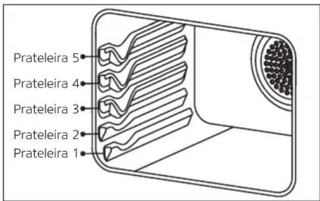
Standard Rack Positions
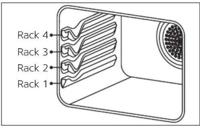
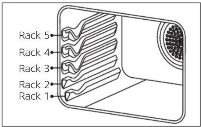
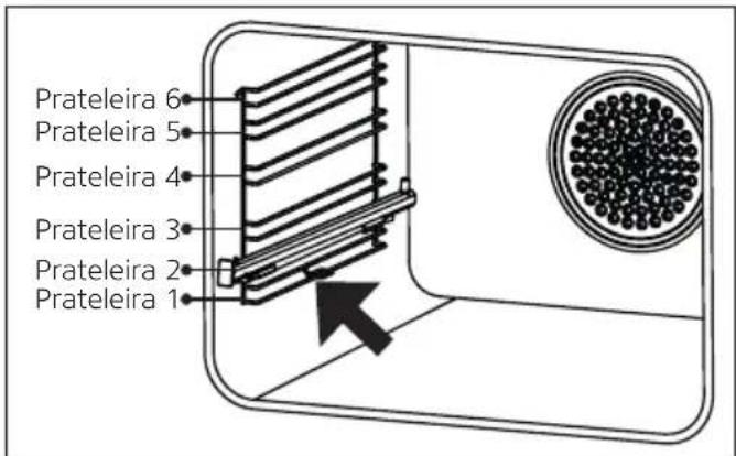
Note: The standard racks can be 4 or 5, depending on the configuration of your oven. Only pay attention to the standard racks of your oven.
Rack positions are shown in the figures above. You may place a deep tray or a standard tray in the lower and upper racks.
\* Wire Rack Positions
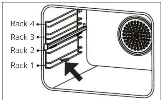
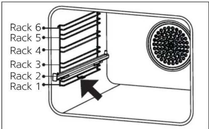
Note: Depending on the configuration of your oven, there may be 4 or 6 wire racks. Only pay attention to the wire racks of your oven.
It is important to place the wire rack into the oven properly. Rack positions are shown in the figures above. You may place a deep tray or a standard tray in the lower and upper wire racks.
Installing And Removing Wire Racks
Press the clips shown with arrows in the figures above, first remove the lower and then the upper side of wire racks. To install wire racks; reverse the procedure for removing wire rack.
USING THE HOB SECTION
Using Gas Hob Section
There are cooker burners working with gas on the upper side of the product. The working system of these cooker burners is based on working separately. Apply the following steps to use cooker burners.
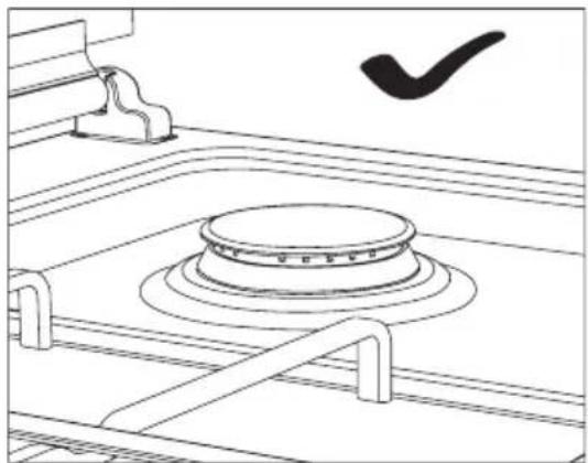
- Make sure that gas burner covers are in a proper position before starting to use cooker burners. The correct placement of the gas burner covers is shown in the figure below.
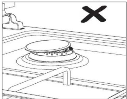
natural_image
Line drawing of a kitchen appliance with a circular lid and handle, no text or symbols presentFigure 12
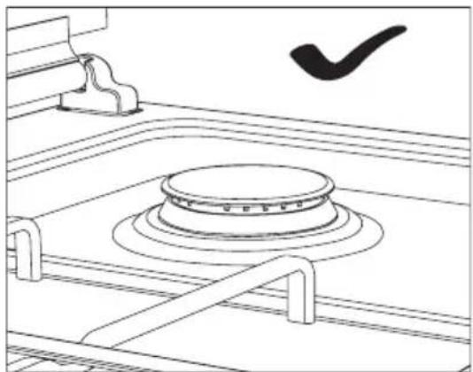
natural_image
Line drawing of a mechanical component with a circular base and a checkmark symbol (no text or labels)Figure 13
- Before operating the cooker burner, make sure that the burner body, burner ducts, burner pool and injector hole are dry and clean.
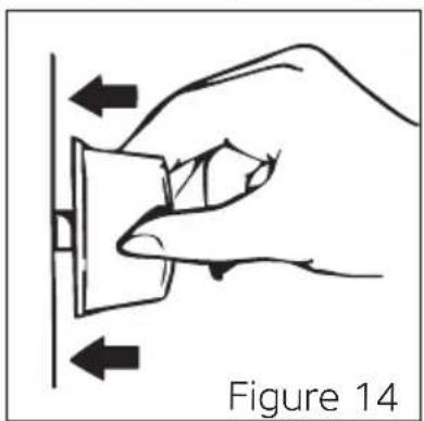
- To use the cooker burner of your preference, first press the knob in the direction of the arrow and wait 5 seconds for air to escape from the pipes (See figure 14).
natural_image
Hand holding a switch with directional arrows indicating left and right movement (no text or symbols)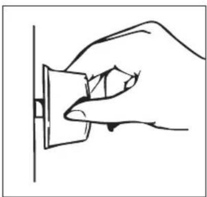
natural_image
Line drawing of a hand inserting a small component into a wall socket (no text or symbols)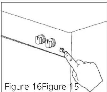
In Models With Manual Ignition; you can ignite the cooker burner of your preference with an igniter (Match, lighter) by rotating the knob (See figure 15).
* In Models With (Auto) Ignition With A Knob; you can ignite the cooker burner of your preference by pressing the knob in the direction of the arrow (See figure 14) and rotating the knob (See figure 15).
* In Button Ignited Models; first, press the button on the control panel (See figure 16). Then, by pressing your preferred cooker burner knob in the direction of the arrow, you can ignite the cooker burner (See figure 14).
WARNING: The ignition takes place by means of electricity in models with (Auto) ignition with a knob and a button. Therefore, make sure that the product is electrically connected before using the product.
RISK OF EXPLOSION AND BURNING: When the cooker burner is ignited, press and hold the knob for a maximum of 15 seconds for the flame checking system to operate. Holding down the knob for more time creates a risk of explosion and burning, as this will lead to the accumulation of gas. If there is no ignition, wait at least one minute. Then try to carry out ignition again.
- Ensure that the grates are fully seated on the hob plate. If the grill does not fit properly, it may cause the materials to be placed on it to spill.
- Make sure that the upper door of the oven is in the fully open position when cooking in the cooker burners. If the upper door is closed while the cooker burners are hot, it may cause the glass to break in the models with glass doors. For this reason, do not close the upper door while the cooker burners are hot.
| Locations Of Cooking Burners | ||
| You can control cooking burner with the help of the knobs on the control panel of the appliance. | ||
| Off position |  |  |
| Full flame |  | 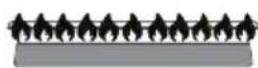 |
| Low flame |  | 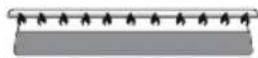 |
| * Flame Failure Device (FFD) | |
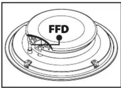 | Wait for 5-10 seconds by pushing the knob forward without releasing your hand from the knob after performing the ignition process in the models with a gas cutter safety assembly in accordance with the instructions. The safety mechanism will be activated within this period and will ensure that the cooker is in working condition.The flame failure device automatically cuts off the gas to the cooker burner in the event that the cooker fire is extinguished for any undesirable reason. |
| * Wok Burner | |
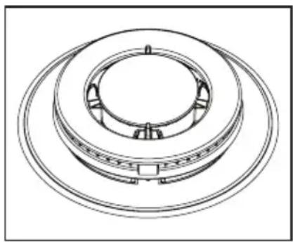 | Wok burner is characterised by its fast cooking. It provides homogeneous heat distribution to the base of the pot at high temperature since it has a double ring flame system. It is ideal for short-term and high-temperature cooking. When you want to use a flat bottom pot in the wok burner, you should take the wok burner pot handler (Wok burner adapter) from the cooker. |
| Pot Diameters To Be Used On Cooker Burners | |||
| When using the cooker burners, use long-handled pots that sit correctly on the surface of the hob as much as possible. This way you will be able to use energy more efficiently. The following table shows the recommended pot diameters to be used according to the gas burners. | |||
| Burner Type | Cooking Pot Diameters | ||
| 50x55 50x60 | / 56x57 60x60 | ||
| Small burner 12-18 | cm 12-18 cm 12-18 | cm | |
| Middle burner 18-20 | cm 18-20 cm 18-20 | cm | |
| Large burner 22-24 | cm 22-26 cm 22-26 | cm | |
| Wok burner 24-28 | cm --- 24-26 cm | ||
| Using Electric Hob Section | |
| WARNING: Power levels may vary depending on the option of your device. | |
| If The Power Level Includes 6 Stages | |
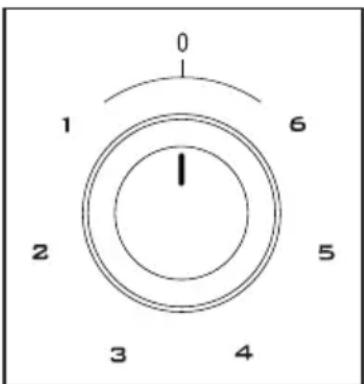 | You can operate the knob on the control panel of the electric cooking zone by turning it to your desired level. By turning the knob on the control panel of the electric cooking zone to off position (0), you can stop the operation. |
| If The Power Level Includes 3 Stages | |
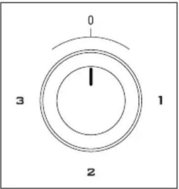 | You can operate the knob on the control panel of the electric cooking zone by turning it to your desired level. By turning the knob on the control panel of the electric cooking zone to off position (0), you can stop the operation. |
| The heat levels of the electric cooking zones (Hot plates) are given in the table. | ||||||
| Electric Cooking Zone (Hot Plate) | Level 1 Level 2 Level | 3 Level 4 Level 5 Level 6 | ||||
| ∅80 mm 200 W 250 W | 450 W --- | |||||
| ∅145 mm 250 W 750 | W 1000 W --- --- | |||||
| ∅180 mm 500 W 750 | W 1500 W --- --- | |||||
| ∅145 mm quick 500 W | 1000 W 1500 W --- --- | |||||
| ∅180 mm quick 850 W | 1150 W 2000 W --- --- | |||||
| ∅145 mm | 95 W | 155 W | 250 W | 400 W | 750 W | 1000 W |
| ∅180 mm 115 W 175 | W 250 W | 600 W | 850 W 1500 W | |||
| ∅145 mm quick 135 W | 165 W 250 W 500 | W 750 W 1500 W | ||||
| ∅180 mm quick | 175 W | 220 W | 300 W | 850 W | 1150 W | 2000 W |
| ∅220 mm 220 W 350 | W 560 W | 910 W 1460 W 2000 W | ||||
| When using the electric cooking zones (Hot plates), operate them idle for 5 minutes at the highest level. This operation will clean out the remains of production. A slight smoke and odour may arise in the meantime. This is normal and not a manufacturing fault. | ||||||
| Proper Pot Use | ||||||
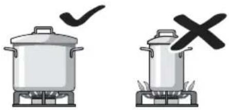 | Use dishes of the appropriate size for each cooking zone. Do not use small dishes in a large cooking zone. Flame should not reach the container sides. | |||||
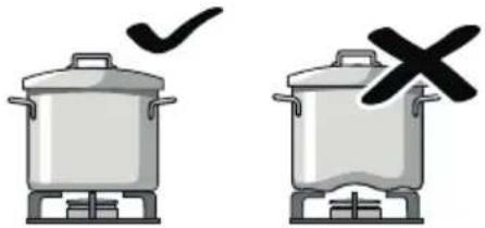 | Do not use containers with convex or concave bases. In this way, dishes can turn down. Use only dishes with a flat bottom. If you are using the wok burner adapter for the cooking process, you can use convex dishes. | |||||
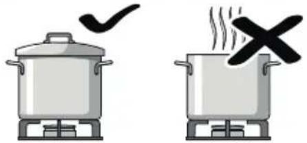 | Do not cook without a lid or with a lid that is half open. This cause you to waste energy. Splashes and overflows may damage the hob surface and cause fire. | |||||
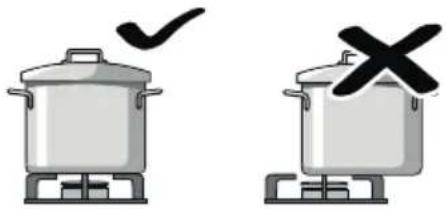 | Center the dish exactly over the cooking zone. Otherwise, it may fall over. | |||||
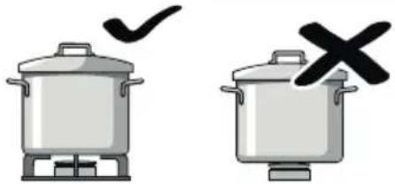 | Never place the utensils directly on the cooking zones, always place them on the grate. Before operating the product, make sure that the grates are in the correct place. | |||||
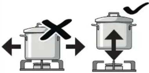 | When you want to put the pot in another cooking zone, instead of sliding it, lift it and put it on top of the cooking zone you want. Avoid impact on the cooking area and do not place weights on it. | |||||
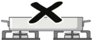 | Never use two burner or heat sources at the same time to heat a pan. While cooking for a long time, avoid using roasting sheet and terrines at maximum temperature. | |||||
| * COOKING FUNCTIONS AND FEATURES | ||||||
| For Electric Oven | ||||||
 | Lower and upper heating are operated together. The food is heated downwards and upwards at the same time. This program may be used to cook foods such as cakes, pizza, biscuits and cookies. Use a single tray for cooking. | |||||
 | Lower heating, upper heating and fan are operated together. Hot air is distributed equally and rapidly inside the oven thanks to the fan. Suitable for cooking foods such as cakes, cookies, lasagne, meat. Use a single tray for cooking. | |||||
 | Turbo and fan operate together. Suitable for cooking on different rack levels. | |||||
 | Grill is operated. Used to grill meats such as steaks and fish. To grill, place the food on the grill and the grill on the top rack (See rack positions). Place tray to the lower rack and put water inside the tray while grilling. | |||||
 | The grill and fan operate together. Hot air is distributed equally and rapidly inside the oven thanks to the fan. Used to grill meats such as steaks and fish. To grill, place the food on the grill and the grill on the top rack (See rack positions). Place tray to the lower rack and put water inside the tray while grilling. | |||||
 | Upper heating and chicken roast setting are operated together. It is suitable for food intended to be roasted by rotating. | |||||
 | Upper heating is operated. It is used for heating or roasting very small pieces food. | |||||
 | Lower heating is operated. Select this program towards the end of the cooking time if the bottom of the food being cooked shall be roasted, too. Also this function is used for steam cleaning. (See. steam cleaning) | |||||
 | The oven is not heated. Only the fan and lamp work. Suitable for defrosting icy food. | |||||
 | Lower heating and fan are operated together. Hot air is distributed equally and rapidly inside the oven thanks to the fan. Use it to cook food like fruit cakes, etc. | |||||
 | The oven is not heated. Only the fan and lamp work. Suitable for defrosting icy food. | |||||
 | It is used for lighting the oven. The lamp operates automatically across all cooking functions. | |||||
| WARNING: Cooking functions may not be same in every model. Only pay attention to cooking functions of your oven. | ||||||
| For Gas, Gas-Electric (Mixed) Oven | ||||||
 | The grill (Upper) is operated. To grill, place the food on the grill and the grill on the top rack (See rack positions). Place tray to the lower rack and put water inside the tray while grilling. | |||||
 | Grill and chicken roast setting are operated together. It is suitable for food intended to be roasted by rotating. | |||||
 | The oven (Lower) burner is operated. | |||||
 | The oven (Lower) burner and fan are operated. Hot air is distributed equally and rapidly inside the oven thanks to the fan. | |||||
 | It is suitable for foods intended to be cooked by being rotated. | |||||
 | The oven is not heated. Only the fan and lamp work. Suitable for defrosting icy food. | |||||
 | The oven is not heated. Only the fan and lamp work. Suitable for defrosting icy food. | |||||
 | The grill and lamp are operated. To grill, place the food on the grill and the grill on the top rack (See rack positions). Place tray to the lower rack and put water inside the tray while grilling. | |||||
 | The grill, roast chicken setting and lamp are operated together. It is suitable for food intended to be roasted by rotating. | |||||
 | The roast chicken setting and lamp are operated together. It is used for foods intended to be cooked by being rotated. | |||||
 | It is used for lighting the oven. | |||||
| WARNING: Cooking functions may not be same in every model. Only pay attention to cooking functions of your oven. | ||||||
COOKING RECOMMENDATIONS AND WARNINGS
You may find the information about the food types we have tested in our laboratories and whose cooking values we have determined in the following tables. Cooking times may vary as per mains voltage, quality, amount of the ingredients to be cooked, and the temperature. Meals you cook using these values may not appeal to your tastes. You may discover different values by making experiments to achieve different flavours and results that appeal to your taste.
WARNING: Unattended cooking with solid or liquid oil in the appliance is dangerous, it can cause a fire.
WARNING: Ensure that the oven door is completely closed after putting food inside the oven.
WARNING: Steam may come out when the door is opened. Step back and wait for the steam to disappear.
WARNING: During usage, the internal and external surfaces of the oven get hot. As you open the oven door, step back to avoid the hot vapour coming out from the interior. There might be the risk of burning.
WARNING: Your hand may get burnt because of the internal panels of the oven, spilt meals, accessories and hot vapour. Wear kitchen gloves while taking the hot meal out of the oven.
WARNING: While placing food to or removing food from the oven, etc., always use heat resistant oven gloves.
WARNING: Please do not cook the food placing directly on tray / grill. Place the food into the oven in a suitable accessory.
WARNING: Never fill the pan with more than one-third of the oil. Do not leave the kitchen while heating up the oils. Extremely hot oils are a fire hazard.
WARNING: Be careful when using alcohol in your foods. Alcohol will evaporate at high temperatures and may ignite to cause a fire if it comes in contact with hot surfaces.
WARNING: Do not heat closed cans and glass jars. The pressure may lead jars to explode.
WARNING: Never use it at higher oven temperatures than the maximum usage temperature indicated on your baking paper. Do not place the baking paper on the base of the oven.
WARNING: Place the baking paper together with the food into a pre-heated oven by putting it inside a cooker or on an oven accessory (Tray, wire grill etc.).
WARNING: Against the risk of touching the oven heater elements, remove excess parts of the baking paper that hang over from the accessory or container.
WARNING: Do not place the oven trays, plates or aluminium foils directly on the oven base. The accumulated heat may damage the base of the oven.
WARNING: Plastic dishes may melt at high temperatures and damage the appliance. Do not use plastic dishes.
WARNING: Your hand may get burnt because of the internal panels of the oven, spilt meals, accessories and hot vapour. While removing the dried fruit from the oven, wear heat resistant oven gloves.
| COOKING CHARTS | |||||
| For Electric Oven | |||||
| 60 litres | |||||
| WARNING: You should pre-heat the oven for 7-10 minutes before putting the meal in the oven. | |||||
| Food | Cooking function | Cooking temperature (°C) | Cooking rack | Cooking time (Min.) | |
| Cake / 170-180 2-3 35-45 |  | ||||
| Small muffin / 170-180 2 | 25-30  | ||||
| Pie / 180-200 2 35-45 | [KS37] | ||||
| Pastry 180-190 2 20-25 |  | ||||
| Cookie 170-180 2 20-25 |  | ||||
| Apple pie / 180-190 1 50-70 |  | ||||
| Sponge cake 200/150 * 2 | 20-25  | ||||
| Pizza 180-200 3 20-30 |  | ||||
| Lasagne 180-200 2-3 25-40 |  | ||||
| Macaroon |  | 100 | 2 | 50 | |
| Grilled chicken ** |  | 200-220 3 25-35 | |||
| Fish grill ** |  | 200-220 3 25-35 | |||
| Roast beef ** |  | Max. | 4 15-20 | ||
| Grilled meatballs ** |  | Max. | 4 20-25 | ||
| * Do not pre-heat. We recommend you to cook at 200 °C for the first half of the cooking period, and at 150 °C for the remaining half. ** Food shall be turned upside down after the half of the cooking period.80 litres | |||||
| WARNING: You should pre-heat the oven for 7-10 minutes before putting the meal in the oven. | |||||
| Food | Cooking function | Cooking temperature (°C) | Cooking rack | Cooking time (Min.) | |
| Cake / 170-180 2-3 30-35 |  | ||||
| Small muffin / 170-180 2-3 25-30 |  | ||||
| Pie / 180-200 2-3 35-45 |  | ||||
| Pastry 180-190 2-3 20-25 |  | ||||
| Cookie 170-180 2-3 20-25 |  | ||||
| Apple pie / 180-190 2-3 50-70 |  | ||||
| Sponge cake / 200/150 * |  | ||||
| Pizza 180-200 | 3  20-30 20-30 | ||||
| Lasagne | [84ZZ] | 180-200 2-3 25-40 | |||
| Macaroon |  | 100 | 2-3 50-70 | ||
| Grilled chicken ** |  20 2-3 25-35 20 2-3 25-35 | ||||
| Fish grill ** |  | 190 -200-220 | 3-4 25-35 | ||
| Roast beef ** |  | Max. | 4-5 30-35 | ||
| Grilled meatballs ** |  | Max. | 4-5 25-30 | ||
| * Do not pre-heat. We recommend you to cook at 200 °C for the first half of the cooking period, and at 150 °C for the remaining half.** Food shall be turned upside down after the half of the cooking period. | |||||
| * DRYING | |||||
| WARNING: Do not preheat during drying. | |||||
| Food | Cooking Function | Cooking temperature (°C) | Cooking Rack | Cooking duration (Hours) | |
| Sliced banana Fan-cooking functions 100 2 4-5 | |||||
| Sliced apple Fan-cooking functions 100 2 4-5 | |||||
| Sliced orange Fan-cooking functions 100 2 4-5 | |||||
| WARNING: Drying should only be carried out in the drying tray. | |||||
| WARNING: Do not open the oven door until the drying process is complete. | |||||
| WARNING: The thinner the slices, the faster the drying duration is and the aroma of the food is preserved better. | |||||
| WARNING: Your hand may get burnt because of the internal panels of the oven, spilt meals, accessories and hot vapour. While removing the dried fruit from the oven, wear heat resistant oven gloves. | |||||
| * AIR FRYER COOKING | |||||
| While the air fryer is cooking, you can do the cooking according to the values specified in the cooking chart by switching the oven to air fryer mode [bottom-top + fan ( [IMAGE)] . | |||||
| Air Fryer Cooking Chart | |||||
| WARNING: You should pre-heat the oven for 8-10 minutes before putting the meal in the oven. | |||||
| Food | Cooking function | Cooking temperature (°C) | Cooking rack | Cooking time (Min.) | Weight in grams (g) |
| Cookie 170 2-3 10-15 - |  | ||||
| Frozen chicken nuggets 200 | 2-3 2 [C5BW] 750 | ||||
| Frozen fried potatoes 220 2-3 20- |  00 00 | ||||
| Halloumi fries 200 2-3 10-15 | 250  | ||||
| Steak 180 2-3 10-15 1000 | [3ZDS] | ||||
| Meatball 180 2-3 10-15 1000 |  | ||||
| Pizza 200 2-3 10-15 - |  | ||||
| Mushrooms |  | 200 2-3 15-20 1000 | |||
| Chicken rolls |  | 180 2-3 25-30 1000 | |||
| Chicken breast | [X6BK] | 180 2-3 25-30 750 | |||
| WARNING: Air fryer cooking should only be done in the air fryer tray. | |||||
| WARNING: Your hand may get burnt because of the internal panels of the oven, spilt meals, accessories and hot vapour. While removing the dried fruit from the oven, wear heat resistant oven gloves. | |||||
\* STEAM SUPPORTED COOKING
Because it is not cooked in water, vitamins and minerals are retained during steam cooking.
Steam-assisted cooking preserves the flavours of the food better than normal cooking. Also, foods retain their fresh and natural colours this way.
Water consumption depends on the type of food and the length of cooking time.
According to the option of the appliance, you can perform steam supported cooking with two different methods.
- Remove the water container by pulling it out at the points indicated by the arrow. Fill the water container (See figure 17) and slide it in the direction of the arrow to the starting position to put it in place (See figure 18), (See figure 19). After 10 minutes of preheating, slide the water container in the direction of the arrow until you hear a "click" (See figure 20).
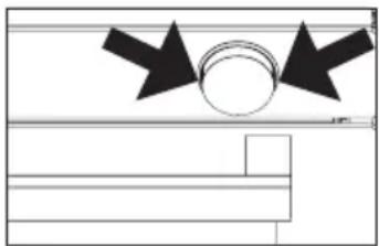
natural_image
Pure technical diagram showing a circular component with two black arrows pointing outward, no text or symbols present.Figure 17
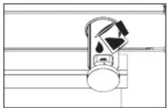
natural_image
Simple line drawing of a mechanical device with no text or symbolsFigure 18
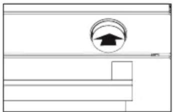
natural_image
Pure technical diagram showing a circular component with an upward arrow, no text or symbols presentFigure 19
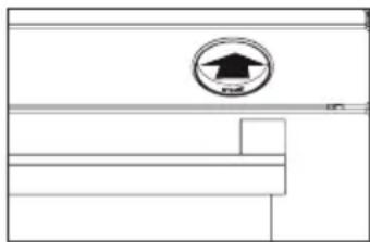
natural_image
Pure architectural or mechanical line drawing with no text, numbers, or symbolsFigure 20
WARNING: If the appliance has steam supported cooking feature; check whether there is water in water tanks while taking the appliance to another place. If there is water in the tanks, you must empty them.
WARNING: Do not use distilled or filtered water. Use only bottled waters. Water should not be replaced by solutions that are flammable, alcohol-containing or with solid particles. Never use mineral water or other liquids!
WARNING: The maximum refill is 250 milliliters and the minimum refill is 65 milliliters.
WARNING: When filling the water container, never exceed the maximum marking!
WARNING: For each cooking process, observe the amount of water for the food as indicated in the cooking chart.
WARNING: Do not remove the water container while cooking is in progress.
WARNING: If possible, use dishes with perforated holes for cooking with steam. This ensures that the steam reaches the food from all sides and that the food cooks evenly.
WARNING: Only use containers which are resistant to heat (Up to 100 °C) and steam. If you want to use plastic containers, check with the manufacturer of the container to see if it is suitable for the oven.
WARNING: Thick pots such as porcelain, ceramic or earthenware are not very suitable for steaming. Because they are thick, they do not conduct heat well and therefore the cooking times indicated in the tables may be much longer.
Steam Supported Cooking Chart
WARNING: You should pre-heat the oven for 10 minutes before putting the meal in the oven.
| Food | Cooking function | Cooking temperature (°C) | Cooking rack | Cooking time (Min.) | Water amount (ml.) |
| Cookie 170 3 20-25 100 |  | ||||
| Salty cookie 170 3 20-25 100 |  | ||||
| Pastry 180 3 25-30 100 |  | ||||
| Bun 180 3 25-30 100 |  | ||||
| Salmon 180 3 40-45 100 |  | ||||
| Chicken drumstick 200 3 40-45 150 |  | ||||
| Chicken wings 230 4 40-45 100 |  | ||||
| Whole chicken 190-230 3 60-70 250 |  | ||||
| Lamb shank with vegetables 170 3 8 |  250 250 | ||||
| Rosebeef |  | 190 3 55-60 | 200 | ||
| Entrecôte |  | 180 3 35-40 | 250 |
WARNING: Make steam-assisted cooking with a single tray.
WARNING: Steam may come out when the door is opened. Step back and wait for the steam to disappear.
WARNING: Your hand may get burnt because of the internal panels of the oven, spilt meals, accessories and hot vapour. While removing the hot food from the oven, use heat resistant oven gloves.
- Open the cover of the appliance (See figure 21). Remove the water tank cover and fill the tank (See figure 22). Then, close the water tank cover (See figure 23). Close the cover of the appliance and preheat it for 10 minutes. After preheating, you can place the food in the appliance.
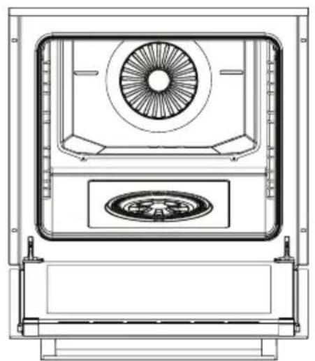
natural_image
Technical line drawing of a mechanical or electrical enclosure with a central fan and circular component (no text or symbols)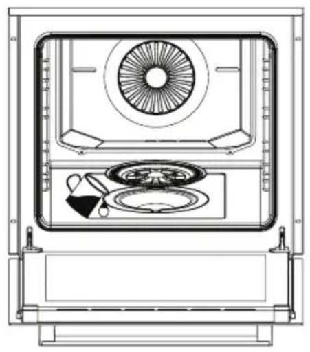
natural_image
Technical line drawing of a front view of an appliance with fan, wheels, and lid (no text or symbols)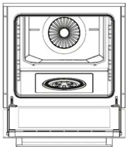
natural_image
Technical line drawing of a mechanical device with central fan and circular component (no text or symbols)Figure 21 Figure 23 Figure 22
WARNING: If the appliance has steam supported cooking feature; check whether there is water in water tanks while taking the appliance to another place. If there is water in the tanks, you must empty them.
WARNING: Do not use distilled or filtered water. Use only bottled waters. Water should not be replaced by solutions that are flammable, alcohol-containing or with solid particles. Never use mineral water or other liquids!
WARNING: The maximum refill is 200 milliliters and the minimum refill is 80 milliliters.
WARNING: For each cooking process, observe the amount of water for the food as indicated in the cooking chart.
WARNING: If possible, use dishes with perforated holes for cooking with steam. This ensures that the steam reaches the food from all sides and that the food cooks evenly.
WARNING: Only use containers which are resistant to heat (Up to 100 °C) and steam. If you want to use plastic containers, check with the manufacturer of the container to see if it is suitable for the oven.
WARNING: Thick pots such as porcelain, ceramic or earthenware are not very suitable for steaming. Because they are thick, they do not conduct heat well and therefore the cooking times indicated in the tables may be much longer.
Steam Supported Cooking Chart
WARNING: You should pre-heat the oven for 10 minutes before putting the meal in the oven.
| Food | Cooking function | Cooking temperature (°C) | Cooking rack | Cooking time (Min.) | Water amount (ml.) | |
| Bread 200 2 20-30 80 |  | |||||
| Chicken 200 2 60-70 150 |  | |||||
| Salmon with vegetables 180 2 | 30-40 |  | ||||
| Chicken drumstick 200 2 25-35 | 100 |  | ||||
| Pastry 190 2 15-25 80 |  | |||||
| Lamb shank with vegetables | 170 2 6 |  150 150 | ||||
| Bun 190 2 15-25 80 |  | |||||
| Entrecôte 180 2 40-50 150 |  | |||||
| Kumpir 190 2 | 90-100 |  150 150 | ||||
WARNING: Make steam-assisted cooking with a single tray.
WARNING: Steam may come out when the door is opened. Step back and wait for the steam to disappear.
WARNING: Your hand may get burnt because of the internal panels of the oven, spilt meals, accessories and hot vapour. While removing the hot food from the oven, use heat resistant oven gloves.
Cleaning Of Water Pool At The Bottom Of The Oven
Depending on the frequency of cooking with steam support-easy steam cleaning and the hardness of the water used, lime stains may form in the water pool at the bottom of the oven. After every 2 or 3 uses, to dissolve limes that may form in the water pool on the bottom of the oven after cooking with steam support-easy steam cleaning processes:
- Put 350 cc of white vinegar (Vinegar acid rate should not be more than 6%) in the water pool at the bottom of the oven.
- Allow the vinegar to dissolve the lime scale at ambient temperature for at least 30 minutes.
- Clean the water pool with a soft wet cloth and dry it with a dry cloth.
WARNING: Do not use cleaning agents containing acids or chlorides to clean the water pool at the bottom of the oven. Do not clean by scraping off limes that may occur in the water pool at the bottom of the oven. Otherwise, the product gets damaged.
| COOKING CHART | ||||||
| For Gas, Gas-Electric (Mixed) Oven | ||||||
| WARNING: You should pre-heat the oven for 7-10 minutes before putting the meal in the oven. | ||||||
| Food | Cooking function | Cooking temperature (°C) | Cooking rack | Bottom burner cooking time (Min.) | Top burner cooking time (Min.) | Total time (Min.) |
| Frozen pizza ** / |  | |||||
| Cookie ** / 175 |  | |||||
| Apple pie / 200 |  | |||||
| Small cake ** / 19 |  | |||||
| Sponge cake / |  | 150 3 20 | 15 35 | |||
| Whole chicken |  | 180-230 | 2 20 50 70 | |||
| Meatball * | [WCB6] | Max. | 3-4 | - | 20-25 | - |
| Steak * |  | Max. | 3-4 | - | 20-25 | - |
| Fish * | [HTAB] | Max. | 3-4 | - | 20-25 | - |
| Sandwich loaf |  | Max. | 3-4 | - | 5-10 | - |
| * The food should be reversed after half of the cooking time elapses. | ||||||
| ** It is recommended to cook food on baking paper placed on the wire rack. | ||||||
MAINTENANCE AND CLEANING
Periodical cleaning extends the appliance's life and reduces frequent problems.
WARNING: Disconnect the electrical connection of the appliance. There is a danger of electric shock.
WARNING: Wait until the appliance cools down before cleaning it. Hot surfaces may cause burns!
WARNING: The surfaces of the burner parts and the grate get slightly dull over time. This is very normal and does not mean any material deterioration.
WARNING: User should not dislocate the resistance during cleaning. It may cause an electric shock.
WARNING: The steam of a steam cleaning device may infiltrate the parts conducting electricity and cause them to short-circuit. Never use a steam cleaning device for cleaning the oven.
WARNING: Never wash any part of the appliance in the dishwasher (Excluding the accessories)!
WARNING: The water container must not be immersed in water and must never be washed in the dishwasher! Do not use very hard sponges or brushes when cleaning the water container.
WARNING: Turn off the appliance before removing the safeguards. After cleaning, install the safeguards according to instructions.
- Do not clean the interior parts, panel, trays or other parts of the appliance with hard tools such as hard brushes, steel sponges, or knives. Do not use abrasive, scratching agents, or detergents.
- Wipe the interior parts of the appliance with a soapy cloth, then rinse and dry it thoroughly with a soft cloth.
- Clean the glass surfaces with special glass cleaning agents.
- Do not use aliphatic or hydrocarbonated detergents. These may cause the door gasket of the oven to swell.
- Never use flammable materials such as acid, thinner, or gas when cleaning your appliance.
- Use potassium stearate (Soft soap) for dirt and stains.
- Clean the control panel with a wet cloth and dry it with a dry cloth.
- The device should be cleaned thoroughly after each use. Thus, food residues are easily cleaned and these residues are prevented from burning when the product is used again later.
- Ensure that you completely wipe any remaining liquids after the cleaning process and that you immediately clean any food that splashes around during cooking.
- Some detergents or cleaning agents may damage the surface. Do not use abrasive detergents, cleaning powders, cleaning creams or sharp objects during cleaning.
- Clean and dry the oven and its accessories after every use.
- Close the oven's door after the inside of the appliance dries completely.
- The appliance should be cleaned thoroughly to avoid bad odours if it will not be used for a long time. Leave the oven's door open after cleaning.
- Replace the appliance's door gasket when pores form or when it cracks. You can order the door gasket from the authorized service.
-
Clean the wire racks in the dishwasher or with a dishwashing detergent and hot water.
-
Do not use abrasive cleaners or sharp metal scrapers to clean the glass as the scratches that may occur on the surface of the door glass may cause the glass to break.
- If the appliance is not used for a longer time than usual, it must be thoroughly cleaned before it is restarted and checked by an authorised technician for proper operation.
- Remove the glass cover of the oven lamp (See lamp replacement) and wipe with a cloth dampened with dish washing detergent and hot water. Clean it with a soft cloth.
- Clean the cooker's cooking zones and all removable parts only by hand with a sponge cloth, a little detergent and hot water.
- Wipe the non-removable hob sections of the oven with a wet cloth.
- Wipe the ignition elements with a very well-wrung cloth. Then dry them with a clean cloth. Make sure that the flame holes and ignition plug are completely dry. Otherwise, there will be no spark at the end of the ignition.
| Assembling The Cooker Burner Parts | |
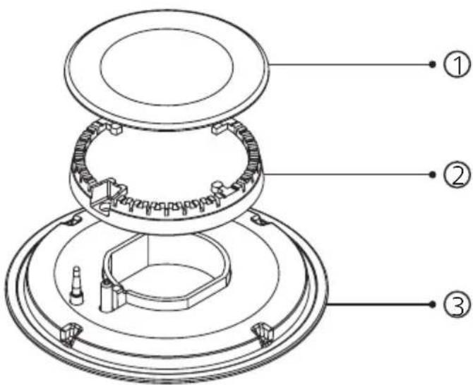 | 1. Burner cover |
| 2. Burner body | |
| 3. Burner pool | |
| Place the cooker's burner body (2) in the burner pool (3). Ensure that the burner body (2) is placed in the burner pool (3) by turning the burner body (2) left and right. After this operation, place the burner cover (1) exactly above the cooker burner body (2). | |
| WARNING: If the cooker burner parts are not properly assembled after cleaning, the ignition performance is affected in a negative way. | |
\* Steam Cleaning
It allows the removal of softened dirt thanks to the steam that forms in the oven.
- Remove all accessories from the oven.
- Put half a litre of water on the tray and place the tray at the bottom rack of the oven.
- For An Electric Oven; set the switch to the lower resistance position (☐). Set the thermostat to 70 °C, and operate the oven for 30 minutes.
For A Gas, Gas-Electric (Mixed) Oven; set the switch to the lower burner position (☐). By setting the temperature adjustment knob (Thermostat) to the lowest position, operate the oven for 30 minutes.
-
After operating the oven for 30 minutes, open the door and wipe the inner surfaces of oven with a damp cloth.
-
For dirt that does not come out, clean the oven using dish washing detergent, warm water, and a soft cloth and dry the area you have cleaned with the help of a dry cloth.
Cleaning Of The Oven Glass
Press the plastic latches on the left and right side as shown in figure 24 and lift the profile by pulling it towards you as shown in figure 25. Glass is free after the profile is removed as shown in figure 26. Carefully pull the glass that has become free toward you. The outer glass is fixed to the oven door profile. You may easily clean the glasses after they have been separated. Once the cleaning and maintenance is complete, you may replace the glasses by performing the removal procedure in reverse. Make sure that the profile is properly placed.
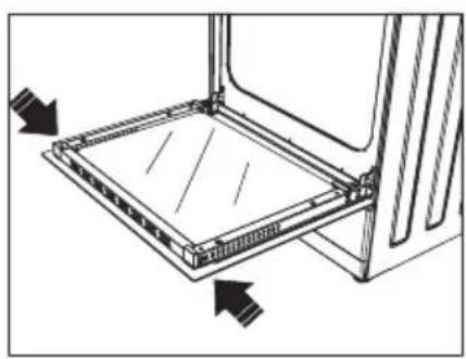
natural_image
Technical line drawing of a 3D printer or scanner assembly with directional arrows indicating orientation (no text or symbols)Figure 24 Figure 25 Figure 26
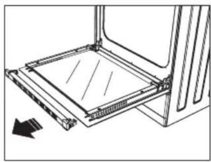
natural_image
Technical line drawing of a mechanical assembly with a rectangular frame and an arrow indicating direction (no text or symbols)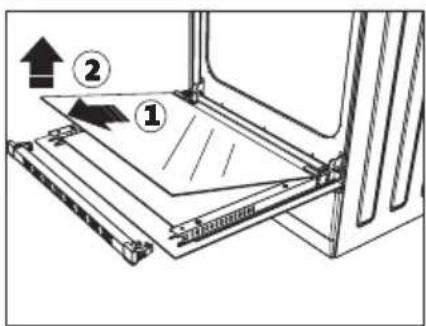
| Cleaning And Assembly Of The Oven Door | |||
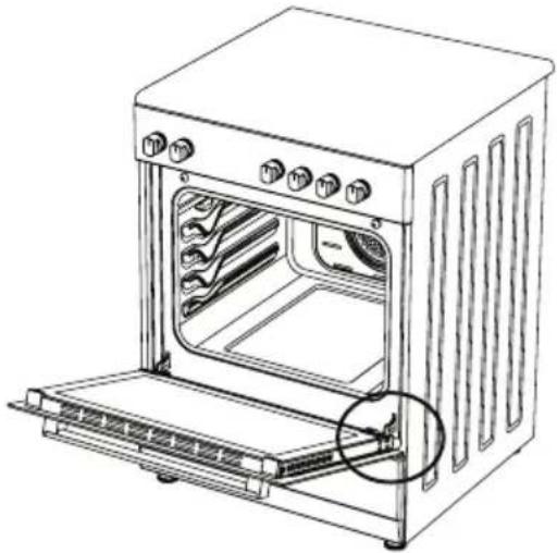 | 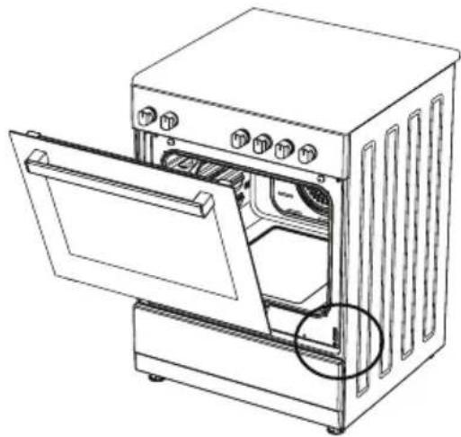 | ||
| Figure 27 Figure 28 | |||
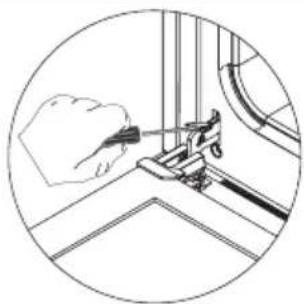 | 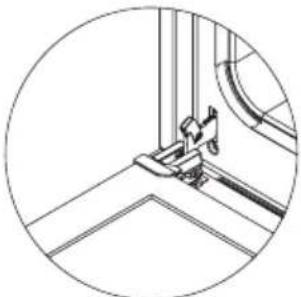 | 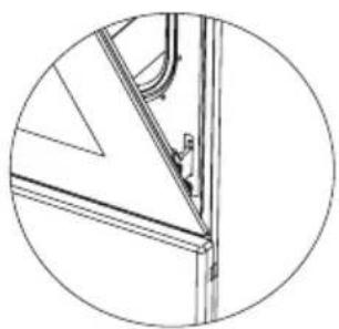 | 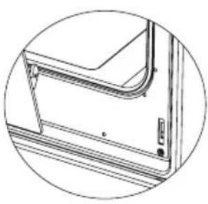 |
| Figure 27.1 Figure 27.2 Figure 28.1 Figure 28.2 | |||
| Open the door completely by pulling the oven door toward you. Then unlock the hinge lock by pulling it upwards with a screwdriver (See figure 27.1). | Set the hinge lock to the widest angle (See figure 27.2). Bring both hinges that connect the oven door to the oven to the same position. | Then close the oven door until it rests against the hinge lock (See figure 28.1). | To remove the oven door, hold the door with both hands when it is at a close level to the closed position, and pull it up (See figure 28.2). |
| To replace the oven door again reverse the procedure for removing the door. | |||
OVEN LAMP REPLACEMENT
WARNING: In order to avoid electric shock, turn off the power connection before replacing the lamp of the oven!
WARNING: In order to avoid burns, wait for it to cool down before replacing the lamp of the oven! Hot surfaces may cause burns!
WARNING: The bulb used in this product is not suitable for illumination of households. The purpose of this lamp is to help the user to see the food.
WARNING: The light bulbs used in this product must be able to withstand extreme physical conditions, e.g. temperatures above 100 °C.
WARNING: In devices with halogen lamps; the user must not look at the halogen lamp.
To Change The Lamp;
- Turn off the electricity.
- Remove the glass protection by turning it counterclockwise (See figure 29). Using plastic gloves may help you if you have difficulty in rotating it.
- Then remove the oven lamp by turning it (See figure 30) if it is type A, or by pulling it (See figure 31) if it is type B.
- Fit a new lamp with the same features.
- Replace the protective glass and connect the unit to the mains.
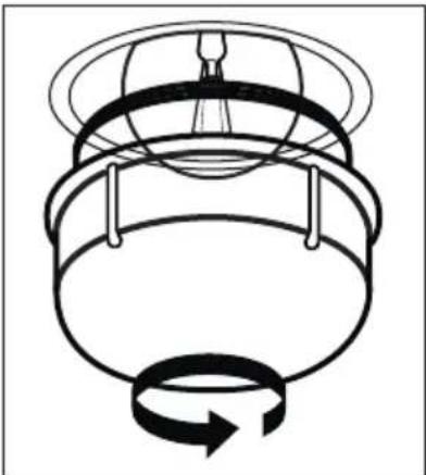
natural_image
Diagram of a mechanical component with a rotating arrow indicating rotational motion (no text or symbols)Figure 29
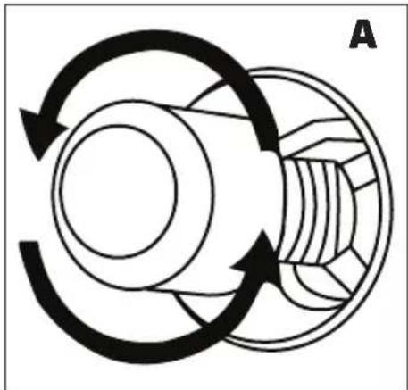
natural_image
Diagram of a mechanical gear or cam mechanism with rotational arrows indicating cycle (no text or symbols)Figure 30
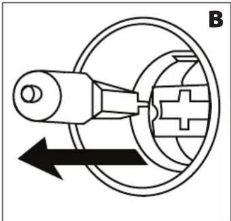
natural_image
Pure mechanical diagram showing a lever and gear mechanism without any text or symbolsFigure 31
Note: This appliance contains a light source whose energy efficiency class is G.
To Chance The Square Lamp;
- Turn off the electricity.
- Remove by pulling the glass protection towards you.
- Then remove the oven lamp by pulling it out.
- Fit a new lamp with the same features.
- Replace the protective glass and connect the unit to the mains.
TROUBLESHOOTING
You may solve the problems you may encounter with your product by checking the following points before calling the technical service.
Check Points
In case you experience a problem about the oven, first check the table below and try out the suggestions. If the problem is persisting, contact the Service Centre.
| Problem Possible Cause What To Do | ||
| Oven does not operate. | Power supply not available. | Check that the power supply is available. |
| Gas supply not available. | Check if main gas valve is open. | |
| Check if gas pipe is bent or kinked. | ||
| Make sure gas hose is connected to the oven. | ||
| Check if suitable gas valve is being used. | ||
| Oven stops during cooking. | Plug comes out from the wall socket. | Re-install the plug into wall socket. |
| Turns off during cooking. | Too long continuous operation. | Let the oven cool down after long cooking cycles. |
| More than one plugs in a wall socket. | Use only one plug for each wall socket. | |
| Oven door is not opening properly. | Food residues jammed between the door and internal cavity. | Clean the oven well and try to re-open the door. |
| Lighter not operating. | Tips or body of ignition plugs are clogged. | Clean tips or body of ignition plugs of gas burners. |
| Gas burner pipes are clogged. | Clean gas burner pipes. | |
| Electric shock when touching the oven. | The power may not be properly grounded. | Make sure power supply is grounded properly. |
| You may be using an ungrounded socket. | ||
| Water dripping. | Depending on the food, water or steam may form in some cases. This is not a fault of the appli-ance. | Let the oven cool down and than wipe dry with a dishcloth. |
| Steam coming out from a crack on oven door. | ||
| Water remaining inside the oven. | ||
| Oven does not heat. | Oven door is open. Close the door | and restart. |
| The oven controls may not be set correctly. | Read the section regarding operation of the oven and reset the oven. | |
| The fuse may have blown or the circuit breaker may have tripped. | Replace the fuse or reset the cir-cuit breaker. If this is repeating frequently, call an electrician. | |
| Smoke comes out of the oven during operation. | When operating the oven for the first time. | smoke comes out from the heat-ers. This is not a fault. After 2-3 cycles, there will be no more smoke. |
| Food on heater. | Let the oven to cool down and clean food residues from the heater. | |
| There is a smell of burning or plastic when using the oven. | Plastic or other not heat resist-ant accessories are being used inside the oven. | Use glass containers suitable for high temperatures. |
| Oven does not cook well. | The door may be opened too of-ten during cooking. | Do not open the oven door too often unless you are cooking something that needs to be ro-tated. If you open the door too often, the internal temperature will drop, which may affect the cooking result. |
| Internal light is dim or does not operate. | Lamp might be failed. | Replace with a lamp having same specifications. |
| Foreign object covering the lamp during cooking. | Clean internal surface of the oven and check again. | |
HANDLING RULES
- Do not use the door and/or handle to carry or move the appliance.
- Carry out the movement and transportation in the original packaging.
- Pay maximum attention to the appliance while loading/unloading and handling.
- Make sure that the packaging is securely closed during handling and transportation.
- Protect from external factors (Such as humidity, water, etc.) that may damage the packaging.
- Be careful not to damage the appliance due to bumps, crashes, drops, etc. while handling and transporting and not to break or deform it during operation.
Future Handling Procedures
The product should be stored and carried in its original box. If the original box is not available, the product must be wrapped with bubble wrap or a thick cardboard and tightly taped.
The product door must be taped to the side walls.
Do not put other items on the product and carry it upright.
Do not drop the product during transport and protect it against impacts.
The product should be kept in normal position during transport.
During handling, the accessories of the product should be fixed with a tape in order not to damage the product.
RECOMMENDATIONS FOR ENERGY SAVING
Following details will help you use your product ecologically and economically.
- Use dark coloured and enamel containers that conduct the heat better in the oven.
- As you cook your food, if the recipe or the user manual indicates that pre-heating is required, pre-heat the oven.
- Do not open the oven door frequently while cooking.
- Try not to cook multiple dishes simultaneously in the oven. You may cook at the same time by placing two cookers on the wire rack.
- Cook multiple dishes successively. The oven will not lose heat.
- Turn off the oven a few minutes before the expiration time of cooking. In this case, do not open the oven door.
- Defrost the frozen food before cooking.
COMPLIANCE WITH WEEE REGULATIONS AND DISPOSAL OF WASTE PRODUCT
Dispose of packaging in an environmentally-friendly manner.
This appliance is labelled in accordance with European Directive 2012/19/EU concerning used electrical and electronic appliances (Waste electrical and electronic equipment - WEEE). The guideline determines the frame work for the return and recycling of used appliances as applicable throughout to the EU.
PACKAGE INFORMATION
This product was manufactured from recyclable and reusable high quality parts and materials. Therefore, do not dispose of this product with other domestic wastes at the end of its life cycle. Take it to a collection point for electrical and electronic equipment. You can ask your local administration about these collection points. Please help to protect the environment and natural resources by recycling the used products. Before disposing of the product, disconnect the electrical plug for the safety of children and make it inoperable. The product's packaging is made of recyclable materials, in accordance with our national legislation. Do not dispose of the packaging waste with the household waste or other wastes, dispose it to the packaging collection areas specified by local authorities.
natural_image
Symbol of a trash bin crossed with no visible text or labels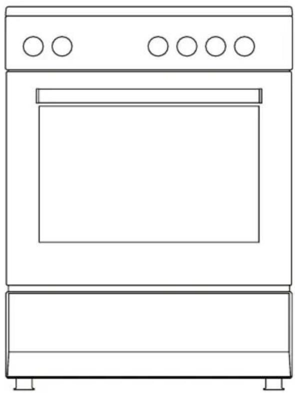
natural_image
Line drawing of a simple kitchen oven with five circular ovens on top (no text or symbols)natural_image
Warning symbol depicting a person pulling a large block inside a triangle (no text or numbers)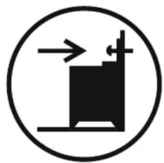
natural_image
Simple black-and-white diagram of a mechanical device inside a circle, with no text or symbols present.natural_image
Hand pressing a small object on a surface, labeled 'Figura 6' (no other text or symbols)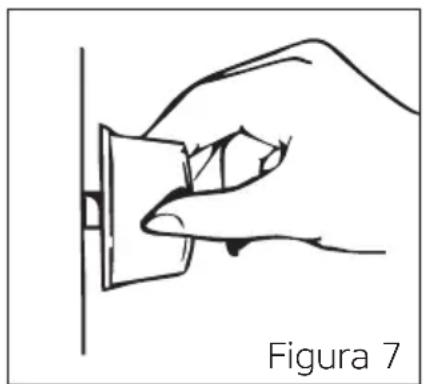
natural_image
Line drawing of a hand holding a small object against a vertical line, labeled 'Figura 7' (no other text or symbols)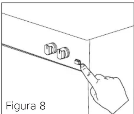
natural_image
Line drawing of a hand pointing at three small objects on a surface, labeled 'Figura 8' (no other text or symbols)natural_image
Diagram showing a device with three horizontal panels inside a container, before and after assembly (no text or symbols)natural_image
Line drawing of a kitchen appliance with a circular lid and handle, no text or symbols presentFigura 12
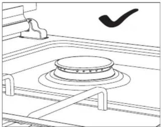
natural_image
Line drawing of a mechanical component with concentric rings and a checkmark symbol (no text or labels)Figura 13
natural_image
Hand holding a switch with directional arrows indicating left and right movement (no text or symbols)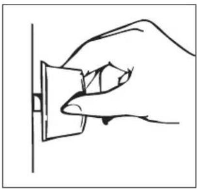
natural_image
Line drawing of a hand inserting a plug into a socket (no text or symbols)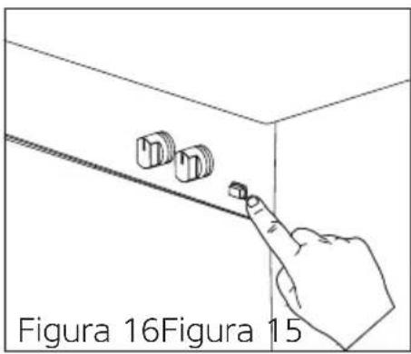
natural_image
Pure technical diagram showing a circular component with two black arrows pointing outward, no text or symbols present.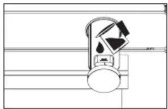
natural_image
Simple line drawing of a mechanical device with no text or symbols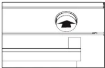
natural_image
Pure technical diagram showing a circular component with an upward arrow, no text or symbols present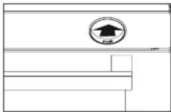
natural_image
Pure technical line drawing of a mechanical or architectural component without any text, numbers, or symbolsFigura 17 Figura 20 Figura 18 Figura 19
natural_image
Technical line drawing of a mechanical or electrical enclosure with a central fan and circular base (no text or symbols)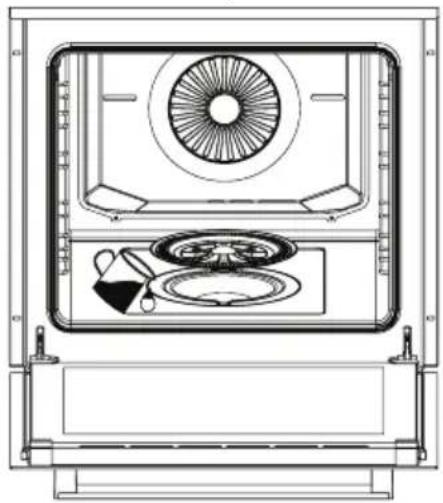
natural_image
Technical line drawing of a front view of an appliance with fan, wheels, and control panel (no text or symbols)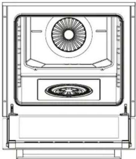
natural_image
Technical line drawing of a mechanical or electrical enclosure with a central circular component and a circular emblem on the base (no text or symbols)Figura 21 Figura 23Figura 22
natural_image
Technical line drawing of a 3D printer or scanner with base and top components, showing internal structure and directional arrows (no text or symbols)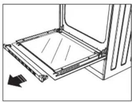
natural_image
Technical line drawing of a mechanical assembly with a rectangular frame and directional arrow (no text or symbols)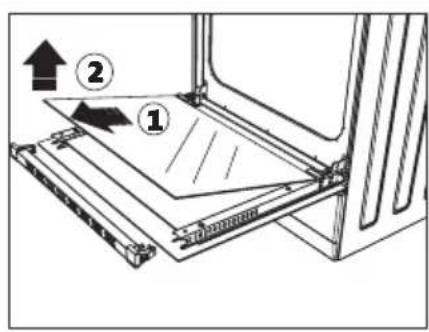
Figura 24 Figura 25 Figura 26
natural_image
Diagram of a mechanical or electrical component with a circular arrow indicating rotational motion (no text or symbols)Figura 29
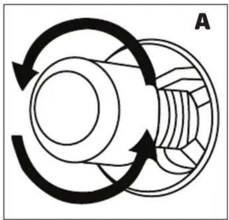
natural_image
Diagram of a mechanical gear or cam mechanism with rotational arrows indicating motion (no text or symbols)Figura 30
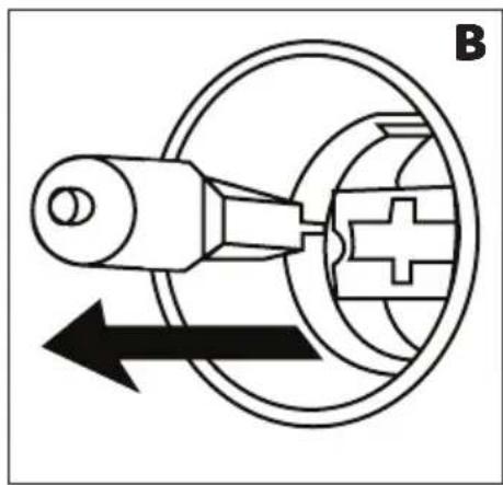
natural_image
Pure mechanical diagram showing a lever and gear mechanism without any text or symbolsFigura 31
natural_image
Symbol of a trash bin crossed with diagonal lines, no text or numbers present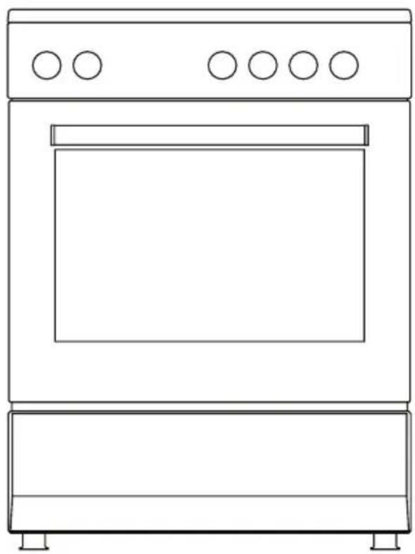
natural_image
Line drawing of a simple kitchen oven with five circular doors on top (no text or symbols)Four Indépendant
Gaz et électrique
50x55 / 50x60 / 56x57 / 60x60 / 60x60 Professionnel
natural_image
Prohibition sign showing a crossed-out diagonal line crossing a barrier with flame-like symbols (no text)natural_image
Warning sign depicting a person pushing a large object inside a triangle (no text or symbols)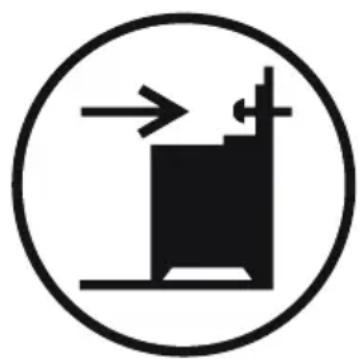
natural_image
Simple black-and-white diagram of a mechanical or electrical component with directional arrows, enclosed in a circle (no text or symbols)\* Fermeture De La Porte Vitrée (En Option)
natural_image
Line drawing of a hand holding a tool inside a circular frame (no text or symbols)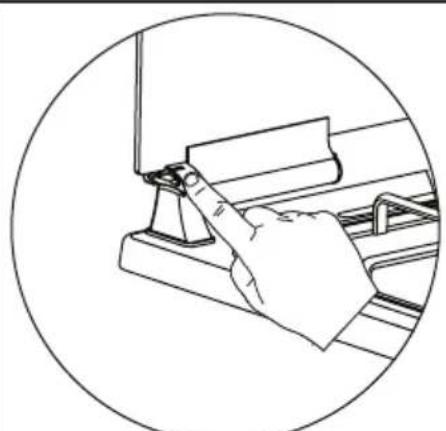
natural_image
Line drawing of a hand pressing down on a mechanical component (no text or symbols)Figure 2 Figure 3 Figure 1
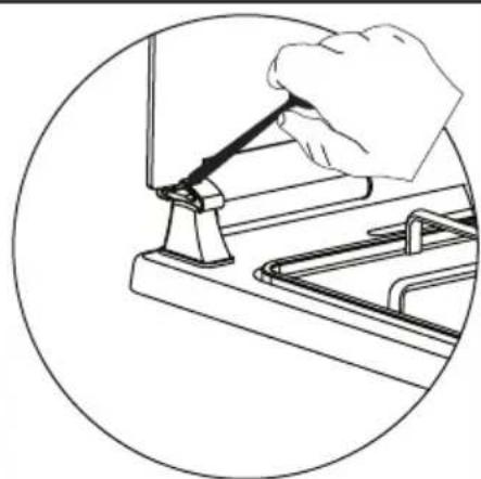
natural_image
Line drawing of a hand using a tool to adjust or install a kitchen sink (no text or symbols)natural_image
Line drawing of a mechanical assembly with multiple valves mounted on a platform (no text or symbols)Figure 4 Figure 5
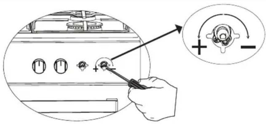
natural_image
Hand holding a switch with directional arrows indicating left and right movement (no text or symbols)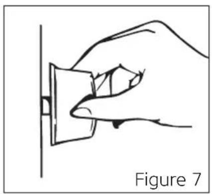
natural_image
Line drawing of a hand holding a small object against a vertical line, labeled 'Figure 7' (no text or symbols on the diagram itself)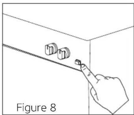
natural_image
Line drawing of a hand pointing at three buttons on a wall, labeled 'Figure 8' (no text or symbols on the diagram itself)natural_image
Technical line drawing of a mechanical fan assembly with labeled component A (no text or symbols beyond label)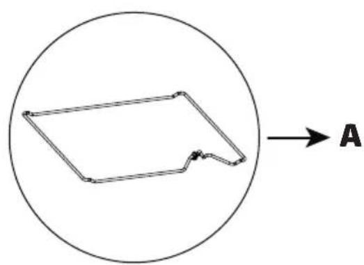
natural_image
Simple line drawing of a polygon within a circle, with an arrow labeled 'A' pointing right (no text or symbols on the shape itself)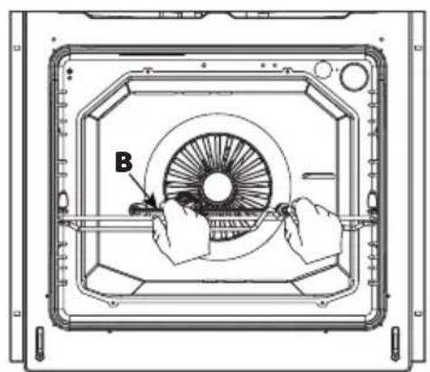
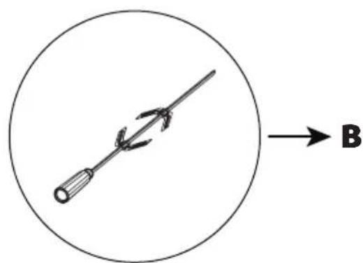
natural_image
Simple line drawing of a tool with a circular head and arrow, labeled B (no text or symbols on the diagram itself)natural_image
Diagram showing a device with three horizontal strips inside a container, before and after processing (no text or symbols)POSITIONS DE LA GRILLE
\* Positions De La Grille Standard
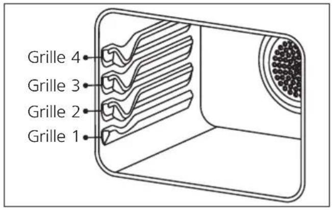
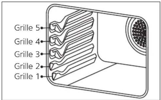
natural_image
Line drawing of a kitchen appliance with a circular fan and handle, no text or symbols presentFigure 12
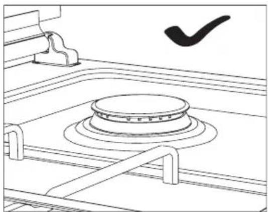
natural_image
Line drawing of a kitchen appliance with a circular lid and handle, no text or symbols presentFigure 13
natural_image
Hand holding a switch with directional arrows indicating left and right movement (no text or symbols)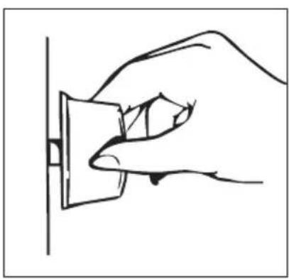
natural_image
Line drawing of a hand inserting a plug into a socket (no text or symbols)
natural_image
Pure diagram of a mechanical or architectural component with arrows pointing to features (no text or symbols)Figure 17
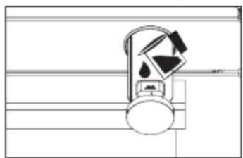
natural_image
Pure electrical circuit lines without any symbolsFigure 18
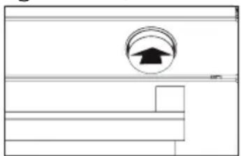
natural_image
Simple line drawing of a room with a circular emblem and horizontal bars (no text or symbols)Figure 19
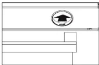
natural_image
Pure architectural line drawing of a building facade with a star-shaped logo on the wall (no text or symbols)Figure 20
natural_image
Technical line drawing of a mechanical or electrical enclosure with a central circular component and a circular emblem on the base (no text or symbols)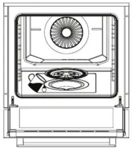
natural_image
Technical line drawing of a front view of an oven or appliance with fan, dish, and utensils (no text or symbols)
natural_image
Technical line drawing of a mechanical device with a circular fan and central hub (no text or symbols)Figure 21 Figure 23 Figure 22
natural_image
Technical line drawing of a mechanical assembly with arrows indicating direction (no text or symbols)Figure 24 Figure 25 Figure 26
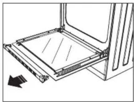
natural_image
Technical line drawing of a mechanical assembly with no visible text or symbols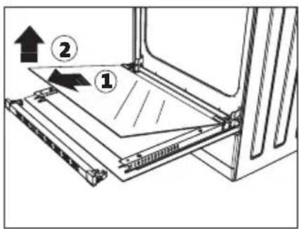
REEMPLACEMENT DE LA LAMPE DU FOUR
natural_image
Diagram of a mechanical component with a rotating arrow indicating rotational motion (no text or symbols)Figure 29
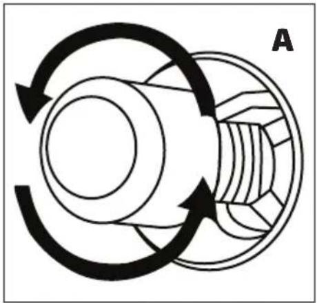
natural_image
Diagram of a mechanical gear or bearing assembly with rotational arrows indicating motion (no text or symbols)Figure 30
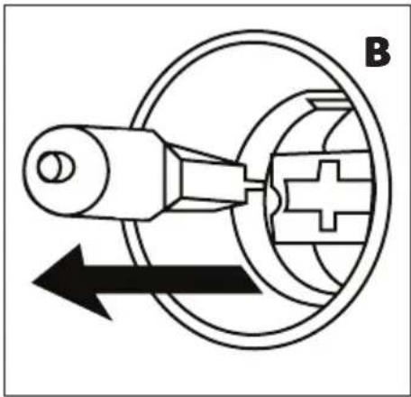
natural_image
Pure mechanical diagram showing a lever and gear assembly without any text or symbolsFigure 31
RÈGLES DE MANUTENTION
natural_image
Symbol of a trash bin crossed with diagonal lines, no text or numbers present
- orima
- MANUAL
- DE
- INSTRUÇÕES
- POSIÇÕES DA PRATELEIRA
- Free Standing Oven
- Dear Customer,
- "Complies with WEEE Regulation"
- Contents
- IMPORTANT WARNINGS
- BURN RISK: Hot surface should be left for cooling down before closing the cover.
- Electrical Safety
- Gas Safety
- THINGS TO DO WHEN GAS ODOUR IS DETECTED
- INTENDED USE
- POWER CONNECTION
- Wiring Diagram
- GAS CONNECTION
- Gas Hose Crossing Path
- Flame Output Speed Setting
- SETTING UP THE APPLIANCE
- WARNING: Appliances working with LPG should not be mounted under the floor level.
- Right Place For Installation
- Correct Installation
- \* Chain Connection
- \* Installation Of The Leg Adapter
- Initial Operation Of The Oven
- Normal Operation Of The Oven
- If The Oven Is An Electric Oven;
- If The Oven Is A Gas, Gas-Electric (Mixed) Oven;
- RISK OF EXPLOSION AND BURNING: When the
- \* COOLING FAN
- Using The Grill
- To Turn On The Grill;
- To Turn Off The Grill;
- \* CATALYTIC PANEL
- Detaching Catalytic Panel
- RACK POSITIONS
- Standard Rack Positions
- \* Wire Rack Positions
- Installing And Removing Wire Racks
- USING THE HOB SECTION
- Using Gas Hob Section
- COOKING RECOMMENDATIONS AND WARNINGS
- \* STEAM SUPPORTED COOKING
- Steam Supported Cooking Chart
- Cleaning Of Water Pool At The Bottom Of The Oven
- MAINTENANCE AND CLEANING
- \* Steam Cleaning
- Cleaning Of The Oven Glass
- OVEN LAMP REPLACEMENT
- To Change The Lamp;
- To Chance The Square Lamp;
- TROUBLESHOOTING
- Check Points
- HANDLING RULES
- Future Handling Procedures
- RECOMMENDATIONS FOR ENERGY SAVING
- COMPLIANCE WITH WEEE REGULATIONS AND DISPOSAL OF WASTE PRODUCT
- PACKAGE INFORMATION
- Four Indépendant
- \* Fermeture De La Porte Vitrée (En Option)
- POSITIONS DE LA GRILLE
- \* Positions De La Grille Standard
- REEMPLACEMENT DE LA LAMPE DU FOUR
- RÈGLES DE MANUTENTION
Brand : Orima
Model : OR-649-XE
Category : Cooker