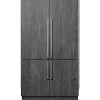
RAT48AMAASR - Refrigerator Dacor - Free user manual and instructions
Find the device manual for free RAT48AMAASR Dacor in PDF.


| Brand | Dacor |
| Model | RAT48AMAASR |
| Product Type | 48" Built-in Refrigerator |
| Width | 47 3/4" (1213 mm) |
| Depth | 25" (635 mm) |
| Height | 83 3/8" (2118 mm) |
| Weight | Approximately 700 lb (317.5 kg) |
| Power Supply | 115 V AC, 15 A, dedicated grounded circuit |
| Refrigerant | R-600a (isobutane) – flammable |
| Main Features | Ice maker, water dispenser, LED lighting, control panel, adjustable FlexZone |
| Required Water Pressure | 30 to 120 psi (207 to 827 kPa) |
| Water Filter | Filter cartridge supplied (install per user manual) |
| Custom Panel | Thickness 3/4" (19 mm); max weight refrigerator 55 lb (25 kg), freezer 22 lb (10 kg) |
| Maintenance and Cleaning | Regular cleaning of surfaces, ice bin, and water filter; do not use electrical appliances inside |
| Safety | Mandatory anti-tip bracket, tip-over hazard, flammable refrigerant gas, manual defrosting prohibited by mechanical acceleration |
| Spare Parts and Repairability | Handles not supplied (kits available), mounting screws to choose according to panel thickness; installation parts included (brackets, covers, trims) |
| Installation | Requires at least 2 people, cabinet width 47.5" or 48" depending on type, depth 24" or 25", height 84" |
| Warranty | Online activation or warranty card to complete |
Frequently Asked Questions - RAT48AMAASR Dacor
User questions about RAT48AMAASR Dacor
0 question about this device. Answer the ones you know or ask your own.
Ask a new question about this device
Download the instructions for your Refrigerator in PDF format for free! Find your manual RAT48AMAASR - Dacor and take your electronic device back in hand. On this page are published all the documents necessary for the use of your device. RAT48AMAASR by Dacor.
USER MANUAL RAT48AMAASR Dacor
Installation instructions
Built-In Refrigerator DRF48*****
Contents
Before you begin... 4
Important
4
Important Safety Instructions 5
State of California Proposition 65 Warning 5 General Safety Precautions 6
Safety and warning information 10
Installation safety 10
Installation Specifications 12
Product Specifications 13
Custom Panel Specifications 14 Handle Specifications 15
Installation 17
Installation requirements 18
Installation preparation 18
Grounding the refrigerator 22
Water-pressure requirements 23
Connecting to the main water supply 24
Cabinet special requirements 25
English2
Installation instructions 26
- Uncrating the Refrigerator 26
- Moving the Refrigerator 27
- Installation preparation 28
- Attaching the anti-tip-bracket 28
- Remove Upper & Lower Door Cover, Kickplate 31
- Attaching the Refrigerator's Top Cover 32
- Adjusting the door Opening Angle 33
- Moving the Refrigerator Into Its Enclosure 34
- Leveling the Refrigerator 36
- Securing the Refrigerator 37
- Attaching the Cabinet Trim 37
- Attaching Panel brackets 38
- Hanging a Custom Panel 41
- Aligning the Panel 42
- Attaching the Door's Interior Covers 45
- Connecting the Water Line 47
- Attaching kickplate and Toe kickplate 48
- Attaching the Door Trim 49
- Attaching Trim Top Cover 50
- Removing the Interior packaging 50
- Adjusting the door spring 50
- Cleaning 51
- Installation Checklist 51
English 3
Before you begin...
Important
natural_image
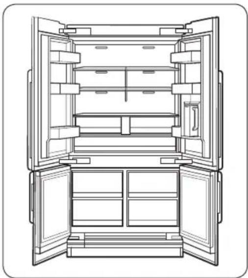
Line drawing of an open refrigerator with doors open, showing internal compartments and storage areas (no text or symbols)Installer
• To promote safety and minimize problems, read this manual thoroughly before starting the installation. Leave this manual with the user.
- Write the appliance's model/serial numbers in this manual for service/maintenance reference.
- Model/serial numbers are on the data label in the refrigerator compartment.
User
- Keep this manual for personal reference and for that of inspectors, service personnel, etc.
SAVE THESE INSTRUCTIONS
English4
Important Safety Instructions
The Important safety instructions and warnings in these instructions are not meant to cover all possible problems and conditions that can occur.
Use common sense and caution when installing, maintaining, or operating this or any other appliance.
Always contact the Dacor Customer Service Team about problems and conditions that you don't understand. See Customer-Service Information.
Safety symbols and labels
These alerts are meant to bring attention to important areas in the manual.
Whenever you see these symbols or labels, read the message carefully before continuing.

DANGER
Immediate hazards that WILL result in severe personal injury or death.

WARNING
Hazards or unsafe practices that COULD result in severe personal injury or death.

CAUTION
Hazards or unsafe practices that MIGHT result in minor personal injury or property damage.
State of California Proposition 65 Warning

WARNING
Cancer and Reproductive Harm - www.P65Warnings.ca.gov.
SAVE THESE INSTRUCTIONS
English
Important Safety Instructions
⚠ WARNING - R600a Refrigerant
This appliance contains isobutane refrigerant, R600a, a natural gas with high environmental Compatibility. However it is also flammable. Please adhere to the warnings below:
- When handling, installing and operating the appliance, care should be taken to avoid damage to the refrigerant tubing.
- Servicing shall be performed by manufacturer-authorized service personnel and component parts shall be replaced with manufacturer-authorized replacement components.
- Refrigeration products contain refrigerants, which under federal law must be removed prior to product disposal.
- Keep ventilation openings in the appliance enclosures or in the built-in structure clear of obstruction.
- In order to avoid the creation of a flammable gas-air mixture if a leak in the refrigerating circuit occurs, the size of the room in which the appliance may be sited depends on the amount of refrigerant used. The room must be 35.3 ft ^3 in size for every 8 g of R-600a refrigerant inside the appliance.
- The installation location should not be exposed to direct sunlight and not placed near any electric appliance or heat source, e.g. stove, oven or hob, radiator, etc.
- If you use two products side by side, for safety reason, be sure to use certified products in explosive gas atmospheres.
- Do not use mechanical devices or other means to accelerate the defrosting process.
- Do not damage refrigerant circuit.
- Do not use electrical appliances inside the food storage compartment of the appliance.
General Safety Precautions
! DANGER
IMPORTANT:
To prevent child entrapment and suffocation when discarding an old appliance:
• Take off the door(s).
- Leave the racks in place so children cannot easily climb inside.
- Cut the prongs off the power plug and discard them.
- Cut the power cable off and discard it separately from the old appliance.
To avoid the possibility of explosion or fire, do not store or use combustible, flammable or explosive vapors and liquids (such as gasoline) inside or in the vicinity of this or any other appliance. Also keep items that could explode, such as aerosol cans away from cooktop burners, ovens and range hoods. Do not store flammable or explosive materials in adjacent cabinets or areas.
SAVE THESE INSTRUCTIONS
English6
WARNING
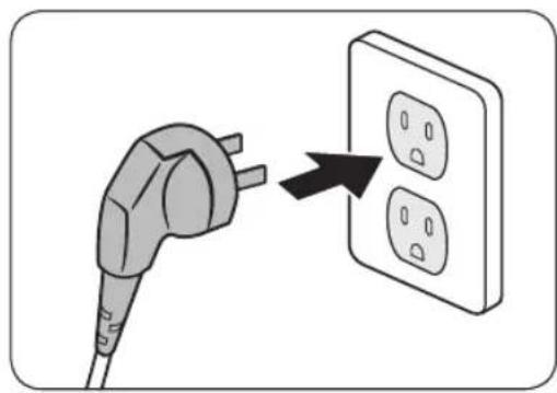
IMPORTANT: This appliance is equipped with a three-prong grounding electric plug for protection against possible electric shock hazards. It must be plugged into a dedicated, grounded, electrical outlet. If only a two-prong electrical outlet is available, it is the responsibility of the customer to have it replaced with a dedicated, properly grounded three-prong electrical outlet.
- Do not kink or pinch the power supply cord of the appliance.
- Never unplug the appliance by pulling on the power cord.
• Always grip the plug firmly and pull straight out from the electrical outlet. - Disconnect this appliance when not in use.
- Do not install, repair, modify, or replace any part of the appliance unless specifically recommended in the literature accompanying it.
• A qualified service technician should perform all other service.
natural_image
Illustration of a plug with three outlets and a black arrow pointing to one outlet (no text or symbols)DO NOT cut or remove the third (ground) prong from the power cord.
DO NOT use an adapter plug.
DO NOT use a power cord that is frayed or damaged.
DO NOT connect the appliance to an extension cord. Keep the power cord away from heated surfaces.
NOTE
• Use of an electrical outlet with a ground
- Use of an electrical outlet with a ground fault interrupter (GFI) is not recommended.
SAVE THESE INSTRUCTIONS
English 7
Important Safety Instructions
WARNING
To reduce the risk of fire, electric shock, serious injury or death when using your appliance, follow basic safety precautions, including the following:
If you receive a damaged product, immediately contact your dealer or builder. Do not install or use a damaged appliance.
Make sure that this appliance has been properly installed according to these installation instructions.
Make sure Install outlet locations according to electric supply location.
Refrigeration equipment and refrigerants must be properly disposed of in a professional and appropriate way, in accordance with the current local regulations and laws which protect the environment. This applies to your old appliance and to your new unit once it has reached the end of its service life. DO NOT dispose of the appliance in a landfill or with urban waste. Contact local waste disposal centers for information on how to dispose of recyclable waste.
Take care when handling, moving, using or disposing of the appliance to avoid damaging the refrigeration system.
Do not install or use outdoors or in wet conditions. This appliance is not designed for installation in a recreational vehicle or boat.
Keep packaging materials away from children. Plastic sheets and bags can cause suffocation.
Connect this appliance to a 115 V, 15 A. circuit that is controlled by a circuit breaker or fuse. This appliance should have its own separate grounded circuit.
Do not kink or pinch the power supply cord of the appliance. Never unplug the appliance by pulling on the power cord. Always grip the plug firmly and pull straight out from the electrical outlet.
Disconnect this appliance when not in use.
Do not install, repair, modify, or replace any part of the appliance unless specifically recommended in the literature accompanying it. A qualified service technician should perform all other service.
Before performing any type of service, switch power off at the circuit breaker panel.
This appliance is not intended for use by persons (including children) with reduced physical, sensory abilities, or lack of experience and knowledge, unless they are properly supervised by a person responsible for their safety. Children must be supervised for their safety.
Never allow anyone, including children to sit, stand or climb on any part of the appliance, including the door. Doing so may cause damage, serious injury or death.
SAVE THESE INSTRUCTIONS
English8
If the power cord is damaged, it must be replaced by the manufacturer or a qualified service technician in order to avoid a safety hazard. Do not tamper with the controls.
Clean this appliance regularly as instructed in the Care and Cleaning section of the User manual. Clean the ice bucket or drawer regularly.
When the freezer is functioning, do not touch the inner stainless steel surfaces with wet or damp hands, since skin may stick to the very cold surfaces.
Do not use any type of electrical equipment inside the refrigerator or freezer compartments.
Do not obstruct any of the vents or openings on the appliance.
To avoid risk of the appliance tipping over it is mandatory to secure the appliance to the wall by means of the two supplied anti-tip brackets.
Use this appliance only for its intended purpose: the storage of food and beverages. It is not intended for commercial or industrial use.
Be careful when installing electrical component box is damaged or not by the shock departure.
Open and hold the handle when opening and closing the door.
When you open and close the door, be careful not to put your hands in the doorway.
SAVE THESE INSTRUCTIONS
English
Safety and warning information
Installation safety
Location and installation safety
WARNING
- Before installing the refrigerator, connect it to a power outlet and turn the refrigerator ON to make sure the refrigerator is working.
- Choose a location away from the heat of a heater, boiler, or direct sunlight.
• Install the unit where air flows freely and where the refrigerator is well ventilated.
• Install the unit so that air flows unobstructed through the front air grill. If the air circulation is not ensured, it may interfere with the normal functioning of the product. - Outside animals (rodents) can chew on the power cord and cause a fire; therefore, install the unit where there is no access to animals.
- If the cabinet is made of soft material (ex: plaster, etc.), it can have a weak structure and be damaged. Therefore, use a cabinet made of sturdy, strong material.
• Install the refrigerator with a team of at least 2 people.
• Refer to the dimensions of the cabinet and prepare the cabinet with good air circulation. - Use cabinet that will not warp from product heat emissions or humidity from the opening and closing of the refrigerator.
NOTE
This refrigerator is a "built-in" style refrigerator, meaning that the refrigerator requires installation inside a recess in existing kitchen cabinetry.
Before moving the refrigerator, clear the route to the location where it will be installed. Check all product dimensions and the tipping radius with any doorways, hallways, stairs, corners, etc., to ensure a clear passageway.
WARNING
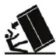

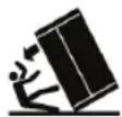
Tip Hazard
This appliance is very heavy on the top and prone to tip over when not securely installed.
Keep doors taped closed until refrigerator is in its final position and ready to be secured in place.
Use two or more people to move and install refrigerator.
Failure to do so can result in death or serious injury.
English10

DANGER

natural_image
Three identical black spikes on a horizontal line, no text or symbols presentExplosion Risk
Keep flammable materials and vapors - such as gasoline - away from the refrigerator.
Failure to do so can result in death, explosion, or fire.
Installation Specifications
WARNING
Observe all governing codes and ordinances during planning and installation. Contact your local building department for further information.
WARNING
Electrical and grounding connections must comply with the applicable portions of the national electrical code and/or other local electrical codes.
This appliance comes with an electrical cord with a three-prong grounding plug for a 115 Vac, 15 Amp. power supply. Plug it into a 115 Vac, three-prong, grounding electrical outlet only.
Unless a whole house filtration system is installed, the provided water filter cartridge, should be installed according to the User manual.
Turn OFF the ice maker using the ICE key whenever the water supply valve is turned off. The ICE key is lit when the ice maker is on.
The appliance features a lighting system with high intensity LED lamps. Do not stare into these lamps when they are on to avoid possible eyesight damage.
English12-
Product Specifications
natural_image
Simple line drawing of a two-decker cabinet with handles and a labeled dimension (no text or symbols)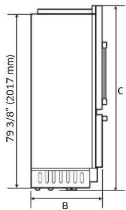
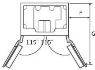
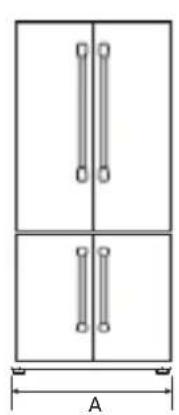
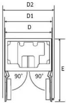
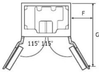
| Callout 48" | |
| A (Width) 47 3/4" (1213 mm) | |
| B (Depth) 25" (635 mm) | |
| C (Height) 83 3/8" (2118 mm) | |
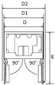
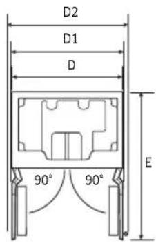
| D 47 1/4" (1200 mm) | |
| D1 (with Panel) 49 11/16" (1262 mm) | |
| D2 (with Contemporary Handle) 55 7/32" (1403 mm) | |
| E 51 1/2" (1308 mm) | |
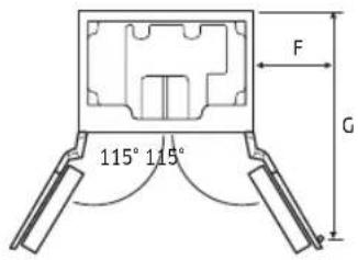
| F 23 45/64" (602 mm) | |
| G 50 25/64" (1280 mm) | |
Product Specifications
Custom Panel Specifications
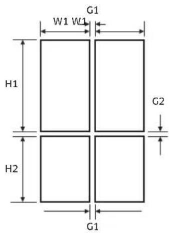
| Callout 48" | |
| W1 23 25/32" | (604 mm) |
| H1 49 3/16" | (1249 mm) |
| H2 30 9/16" | (776 mm) |
| G1 5/32" (4 mm) | |
| G2 5/32" (4 mm) | |
| Panel Thickness 3/4" | (19 mm) |
Do not exceed the max load that the custom panel can endure. Before crafting the panel, check the strength of the panel's material and the load of attachments to the panel.
| 48” | |
| Custom PanelMaximum Weight | Fridge : 55 lb (25 kg), Freezer : 22 lb (10 kg) |

NOTE
- Standard Custom panel thickness is 3/4" (19 mm).
English14
Handle Specifications
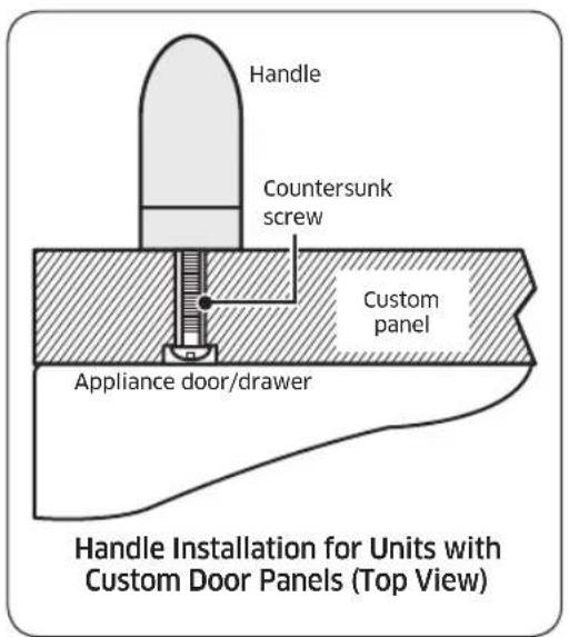
Before installing the custom panels, you must first install the door/drawer handles. With custom panel models, you have the advantage of being able to select a handle style that meets your own personal taste. Handles are not provided with custom panel models. Selected handle kits are available through your dealer. Dacor does not advise the use of single pull knobs.
Most handle kits do not include the necessary mounting screws because screw length varies with panel thickness.
The panel craftsman needs to select and purchase the required fasteners for the installation. The screw heads must be countersunk into the panel to prevent interference during depth adjustment.
CAUTION
We recommend installing a handle for a custom panel. Without the handle, you may catch your fingers in the door when opening or closing the door.
Product Specifications
Attach the handle
WARNING
Follow these instructions to attach the handle. Otherwise, the handle may be damaged or malfunction.
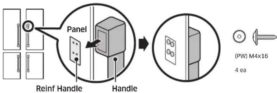
- Put the reinforced handle support on the rear of the door panel, and then put the handle on the front of the door panel.
- As shown, tighten the 4 screws on each of the upper and the lower sides of the handle. Do not tighten them excessively.
English16-
Installation

WARNING
Do not install the appliance:
- outdoors,
- in an environment with dripping water.
Appliance is very heavy :
T 48" approx. 700 lb / 317.5 kg
Installation room
The appliance should be installed in a dry, ventilated room.
Stable installation
The appliance is very heavy and has a tendency to tilt forwards when the appliance door is opened.
Do not open the door until there is no possibility of the appliance tipping over. The most secure way to install the appliance is to use the supplied anti-tipping devices.
Floor
The subsurface must be level and even in order to ensure that the appliance is securely installed and works correctly.
The subsurface must be made from a hard, non-flexible material.
Aligning the appliance
To ensure that the appliance functions correctly, it must be levelled properly. If the appliance is not level, water may flow out of the ice maker, ice cubes may be irregular or the doors may not close properly.
Installation requirements
Installation preparation
Cabinet installation parts
Using the table below, verify that all installation parts are present as you unpack the appliance.
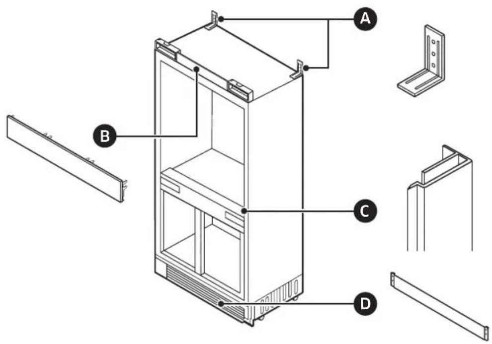
Check the installation parts when unpacking.
| PARTS Quantity | ||
| A ANTI | -TIP BRACKET 2 | |
| B CAB | TOP COVER 1 | |
| C CAB | NET SIDE TRIM 2 | |
| D KICK | PLATE 1 | |
English18-
Door installation parts
Using the table below, verify that all door-installation parts are present as you unpack the appliance.
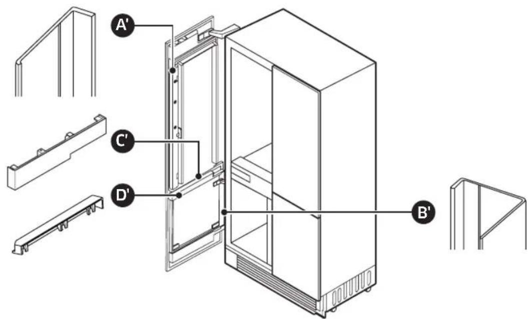
Check the installation parts when unpacking.
| PARTS Quantity | ||
| A' | DOOR TRIM (SIDE) REF L 2 | |
| DOOR TRIM (SIDE) REF R 2 | ||
| DOOR TRIM (SIDE) FRE L 2 | ||
| B' DOOR TRIM (SIDE) FRE R 2 | ||
| C' LOWER DOOR CAP REF L/R 2 | ||
| D' UPPER DOOR CAP FRE L/R 2 | ||
Installation requirements
Screw and Nut
 |  | M6x12 44 ea (TH) M4x12 | 44 | [90TY] |
| [Y3AO] | [ABCY] | (TH) M4x16 12 ea M4x35 | [625Z] | 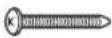 |
 | [8KD0] | M13 8 ea ø6x30 6 ea | 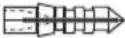 |
English20
Tools required
| No. Tool No. Tool | |||||
| 1 | 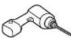 | Electric Screwdriver | 8 |  | Protective Floor Mat |
| 2 | 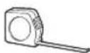 | Measuring Tape | 9 |  | Stepladder |
| 3 | 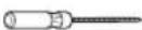 | Flat/Slot Head Screwdriver | 10 | 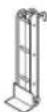 | Appliance Dolly |
| 4 | 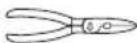 | Cutter (Scissors) | 11 | 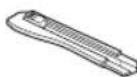 | Cutter |
| 5 | KKHA] | Adjustable Wrench | 12 | 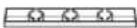 | Level |
| 6 | 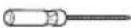 | Phillips Head Screwdriver | 13 | 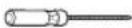 | Star Head Screwdriver (T20) |
| 7 | 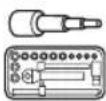 | Ratchet | 14 | 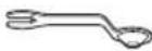 | Combination Wrench |
| 3/8" (10 mm), 1/2" (13 mm) | 3/8" (10 mm), 1/2" (13 mm) | ||||
Installation requirements
Grounding the refrigerator
CAUTION
Electrical and grounding connections must comply with the applicable portions of the national electrical code and/or other local electrical codes.
This appliance comes with an electrical cord with a three-prong grounding plug for a 115 Vac, 15 Amp. power supply. Plug it into a 115 Vac, three-prong, grounding electrical outlet only.
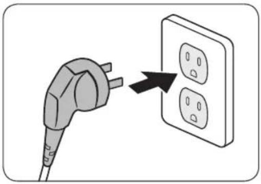
natural_image
Illustration of a plug connecting to an electrical outlet with three outlets (no text or symbols)DO NOT, UNDER ANY CIRCUMSTANCES, CUT OR REMOVE THE THIRD (GROUND) PRONG FROM THE POWER CORD.
DO NOT USE AN ADAPTER PLUG TO CONNECT THE REFRIGERATOR TO A 2-PRONG OUTLET.
DO NOT USE AN EXTENSION CORD WITH THIS APPLIANCE.
WARNING
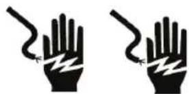
Electric Shock Hazard
Plug into a grounded, dedicated 3-prong outlet.
Do not remove the ground prong.
Do not use an adapter.
Do not use an extension cord.
Failure to follow these instructions can result in death, fire, or electric shock.
English22-
Water-pressure requirements
A cold water supply with water pressure from 30 to 120 psi (207 to 827 kPa) is required to operate the water dispenser and ice maker.
If you have questions about your water pressure, call a licensed, qualified plumber.
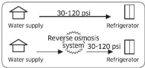
flowchart
graph LR
    A["Water supply"] -->|30-120 psi| B["Refrigerator"]
    C["Water supply"] -->|30-120 psi| D["Refrigerator"]
    E["Reverse osmosis system"] -->|30-120 psi| D
Reverse osmosis system in the water supply
IMPORTANT: The pressure of the water supply leaving a reverse osmosis system going to the refrigerator's water inlet valve must be from 30 to 120 psi (207 to 827 kPa).
Installation requirements
Connecting to the main water supply
Before connecting the refrigerator's water line to the house's main water supply, you need to familiarize yourself with the house's plumbing layout.
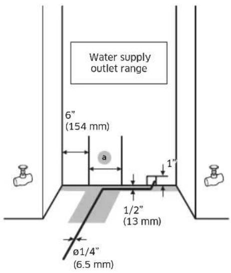
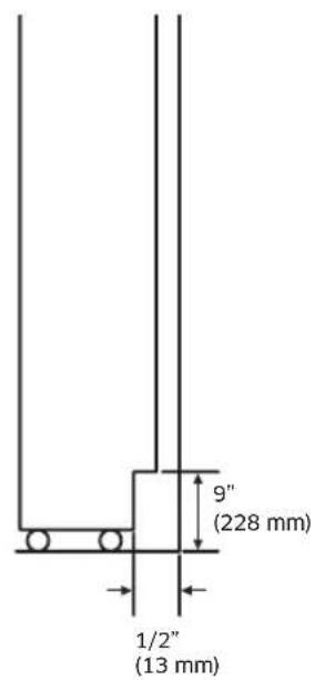
| Callout 48" | |
| a 15" (381 mm) | |
- Decide how best to use the plumbing layout. Then
-
Tap into the main water line while following these requirements:
-
The installer must provide the 1/4" (6.5 mm) water line and all fittings.
- The water line must be long enough to provide slack to allow the refrigerator to be moved for floor cleaning and servicing, without the need to first disconnect the water line.
- All new installations must meet local plumbing code requirements.
- The water shutoff should be placed in the base cabinet on either side of the refrigerator or in some other easily accessible area.
- If the water shut-off valve is placed in the back wall behind the refrigerator, it must be at an angle so that the water line is not kinked when the refrigerator is pushed into its final position.
- Make sure the water supply pipe is within the range shown in the 1" illustrations.
- The water hose is positioned within 1/2" from the back wall, and is withdrawn to the front along the gray-colored area in the figure above. The water hose must be taped on the floor.
English24
Cabinet special requirements
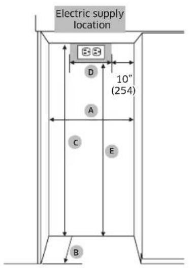
A : Cabinet Width
B : Cabinet Depth
C : Cabinet Height
D : Electrical supply width location
E : Electrical supply height location
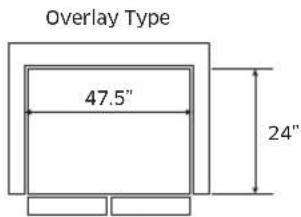
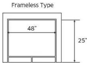
| Callout 47.5" 48" | ||
| A (Width) 47.5" (1207 mm) 48" (1220 mm) | ||
| B (Depth) 24" (610mm) 25" (635 mm) | ||
| C (Height) 84" (2134 mm) | ||
| D 28" (712 mm) | ||
| E 80" (2032 mm) | ||
- B: Includes the standard door panel thickness with 3/4".
- Installation inside a cabinet of this width allows the refrigerator trim to be attached directly to the surrounding cabinets.
- For a 48" or wider cabinet, insert the spacers in the side walls of the cabinet to reduce the gap from the refrigerator.
Installation instructions
1. Uncrating the Refrigerator
Check the appliance for transit damage.
Do not install the appliance if it is visibly damaged.
If in doubt, contact your dealer.
- Remove the PP-banding, cardboard crate, EPS, and Pe-bag.
- Remove the brackets from the pallet by unscrewing the bolts (five per bracket).
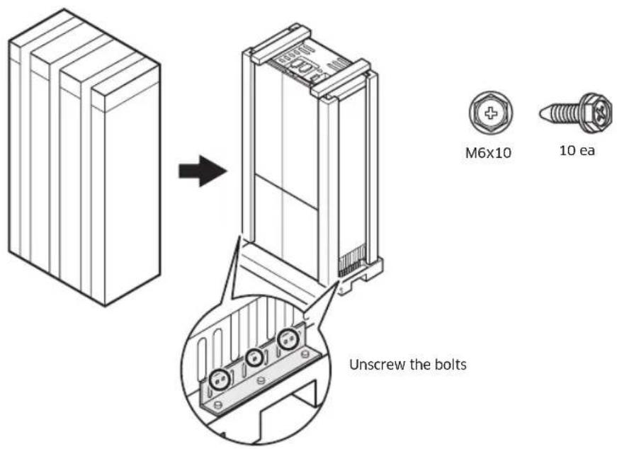

CAUTION
Use caution not to damage the appliance when unloading it from the wooden packing.
English26-
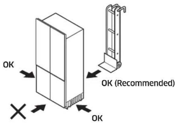
- As shown, insert the hand truck between the appliance and the wooden packing. While tilting the appliance up to the rear, unload it from the wooden packing.

2. Moving the Refrigerator

WARNING
The appliance is very heavy. When moving the refrigerator, all personnel must take care not to injure themselves or the appliance.
- Secure the refrigerator to a suitable means of transport (preferably an appliance dolly), and move the refrigerator near its installation cabinet.
- Move and install with a minimum of two persons.
- Be very careful to avoid floor damage. Delicate flooring should be protected with plywood, hard cardboard, or similar material.
- Before moving the refrigerator, verify that it will fit through all door openings, stairwells, and overhead obstructions.
- TIPPING HAZARD: The refrigerator is large, heavy, and tips easily when not secured. Always move the refrigerator in an upright position if possible. If not, move the refrigerator on its back. Secure the doors shut during transport.
Installation instructions
WARNING
Be careful that electrical component box is not damaged when installing.
3. Installation preparation
Unpack installation materials and accessories.
See the Installation preparation section on Installation Requirement chapter.
4. Attaching the anti-tip-bracket
WARNING
To keep the unit from tipping forward, an anti-tip bracket must be installed. Before attaching the bracket, ensure that no electrical wiring or plumbing is in the area where the screws will penetrate. Two such brackets per appliance are required.
CAUTION
Always wear safety glasses and other necessary protective devices or apparel when installing or working with anchors.
Dacor does not recommend that you anchor the anti-tip bracket in light-weight masonry (e.g., block, brick) or in new, uncured concrete.
Make sure the wall or the cabinet that the brackets are studded in has enough strength to withstand the safety load. If you have to use the spacer, make sure that the spacer is studded on a rear wall that is strong enough to withstand the safety load.
English28-
- Bracket height is measured from the floor and depends on the cabinet height.

NOTE
Bracket height
= Cabinet height - 3 25/32" (96 mm)
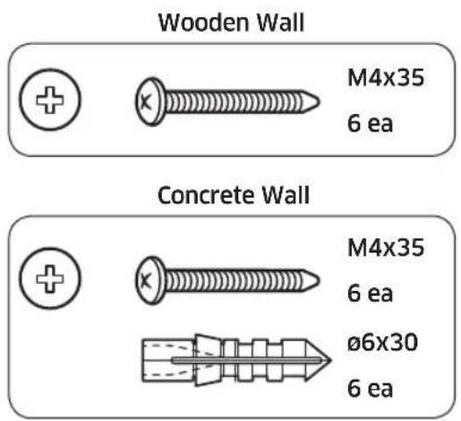
- Attach the anti-tip brackets. Ensure the screws hold the bracket tightly.
The anti-tip brackets must extend at least 2" (50 mm) over the appliance to secure the appliance. If this minimum length cannot be observed for structural conditions it is possible to do this by fastening a spacer (wood) behind the anti-tip angle.
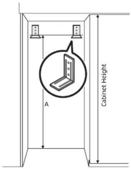
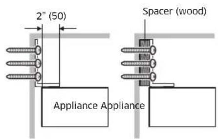
| Option Cabinet height A | |
| 1 83 1/2" (2121 mm) 79 23/32" (2025 mm) | |
| 2 83 3/4" (2127 mm) 79 31/32" (2031 mm) | |
| 3 84" (2134 mm) 80 1/4" (2038 mm) | |
| 4 84 1/4" (2140 mm) 80 15/32" (2044 mm) |
Installation instructions
Anti-tip bracket considerations
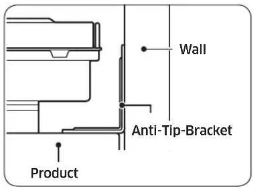
- Bracket positioning: follow the cabinet-specific height table.
- Screws: Tighten all 3 screws on the brackets.
- Push the product up against the rear wall of the cabinet.
- Spacer: If using the spacer, you must follow the positioning specifications of the bracket (see the table above).
CAUTION
- The height of the spacer must be calculated based on the depth of the cabinet.
- The spacer must be fixed separately from the cabinet.
- When using the spacer, tighten the spacer firmly and then tighten the anti-tip bracket.
When installing the product into the cabinet
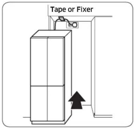
Before positioning the product in the cabinet, plug in the power cord. Then, attach the power cord near the front of the cabinet opening using tape or fixer such as clip, pin, etc.
After positioning the product inside the cabinet, make sure the power cord is positioned on the top of the product (as shown in the in the figure).
English30-
5. Remove Upper & Lower Door Cover, Kickplate
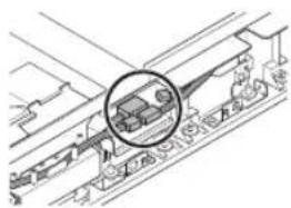
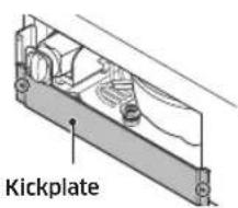
You need to remove the upper/lower door cover and kickplate before you adjust the custom door panel.
-
Upper Door Cover
-
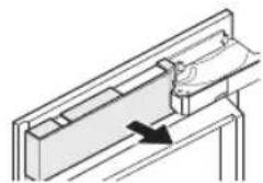
Pull to the arrow direction.
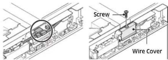
- Remove one screw on the wire cover. (Fridge Left and Right Door)
-
Disconnect housing connectors to separate Upper Door Cover. (Fridge Left and Right Door)
-
Lower Door Cover: Pull to the arrow direction and remove the cover.
- Kickplate: Remove the screws on both sides and remove the kickplate.

natural_image
Pure mechanical assembly diagram showing a lever mechanism with no text or symbols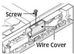
natural_image
Technical line drawing of a mechanical assembly with a magnified inset showing internal components (no text or symbols)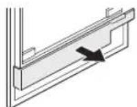
Installation instructions
| Upper Door Cover 2 ea | 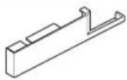 | ||
| Lower Door Cover 2 ea | 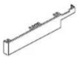 | ||
| Kickplate M4x8 2 ea | 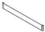 | ||
6. Attaching the Refrigerator's Top Cover
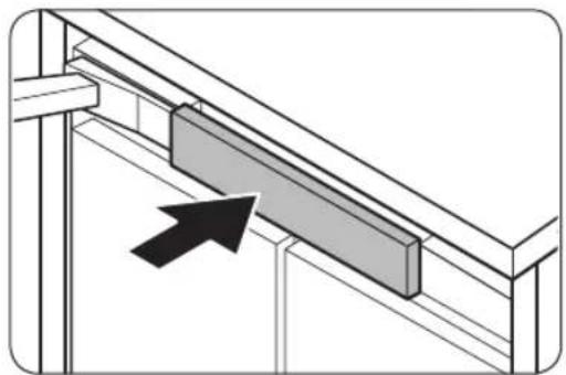
natural_image
Diagram of a structural beam with a highlighted rectangular component and an arrow indicating direction (no text or symbols)Attach the refrigerator's top cover to the hook at the top front of the chassis.
English32-
7. Adjusting the door Opening Angle
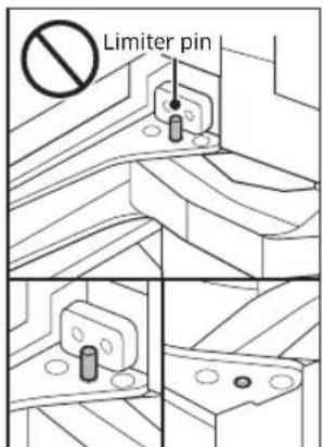
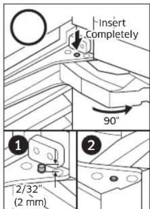
By factory default, the door opens by 115 degrees. You can use the limiter pin to adjust the opening angle down to 90 degrees, depending on the installation conditions.
- Open the door to less than 90 degrees, and then completely insert the limiter pin through the top and bottom holes of the top hinge as shown in illustrations (1) and (2).
- Close the door and make sure the limiter pin does not interfere with the hinge cover.

CAUTION
- Insert the limiter pin before putting the refrigerator into the cabinet.
- If the limiter pin is not inserted completely, the hinge and the hinge cover may get damaged.
Fridge Door
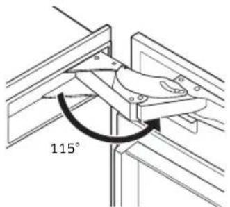
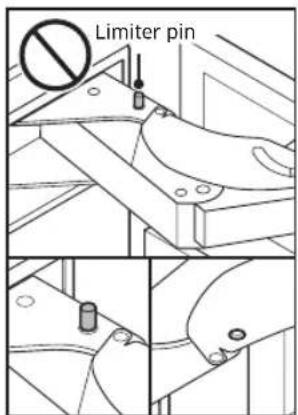
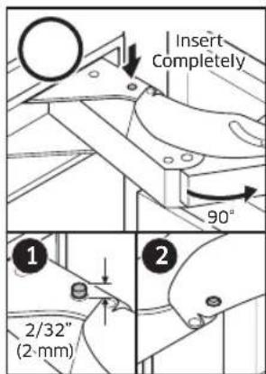
Factory default 115° With limiter pin 90°
Freezer/Flexzone Door
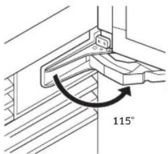
Factory default 115° With limiter pin 90°
Installation instructions
8. Moving the Refrigerator Into Its Enclosure
- According to the type of cabinet, a jig (positioning aid) can be used to align the refrigerator's custom door panel with cabinet by marking vertical line on the cabinet.
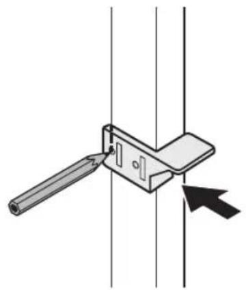
natural_image
Mechanical clamp or bracket assembly with a tool inserted, showing alignment lines and a black arrow pointing to a component (no text or symbols)
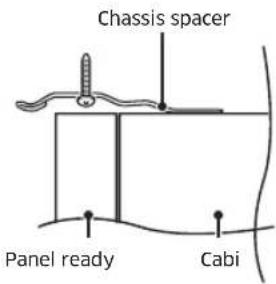
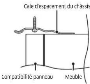
- Position the Chassis spacer to align with your vertical line.
Overlay Type Frameless Type
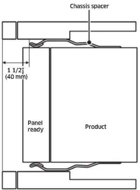
Top view
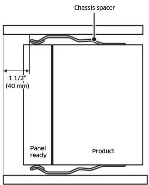
Top view
English34

CAUTION
As you push the refrigerator into its enclosure, take care not to damage the water line and power cord.
The water hose must be fixed to the ground before pulled out to the front. Also, arrange the power cord behind the appliance to ensure that it is not stepped on or over.

WARNING
While moving the refrigerator, take care not to harm assisting personnel or the refrigerator itself.
- Before moving the refrigerator, connect the power cord. Before installation, turn the refrigerator on and make sure the room lamp and the display operate properly with no information code appearing.
- Place packaging cardboard or plywood in the refrigerator's path to protect the flooring while moving the appliance.
- Carefully push the refrigerator into its enclosure. When inserting the refrigerator, make sure it is positioned in the center of the cabinet.
- Align the forward edge of the chassis spacer with the vertical line you marked on the cabinet.
Installation instructions
9. Leveling the Refrigerator
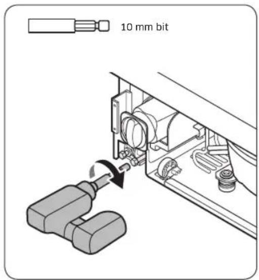
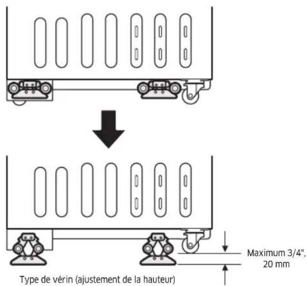
- Using your drill and the bit shown below, engage each of the refrigerator's adjuster shafts in turn, and level the refrigerator. (CW ↑, CCW ↓)
- Adjust the gap between the furniture and CABI TOP COVER to 1/8" (3 mm).
CAUTION
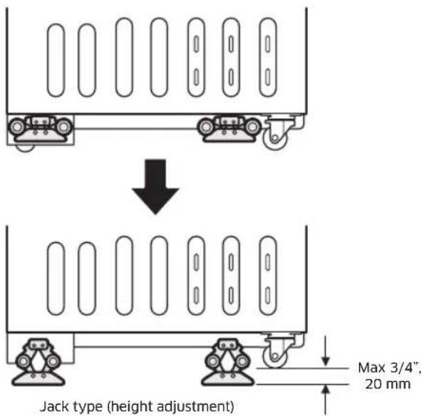
The front and rear leveling legs have a maximum height adjustment of 3/4" (20 mm).
If greater height is required, the installer may raise the refrigerator on a sheet of plywood or runners.
Raising the refrigerator above 3/4" (20 mm) will damage the front and rear leveling components.
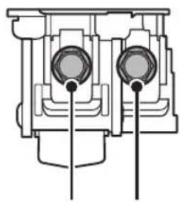
natural_image
Cross-sectional diagram of an internal combustion engine cylinder (no text or labels)Front Rear
Adjustable shaft (10 mm)
English36-
10. Securing the Refrigerator
- Open the fridge & freezer/freshzone+ door.
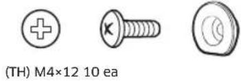
- Secure the refrigerator to its enclosure with (TH) M4×16 screws (6 screws per side, as shown in the graphic).
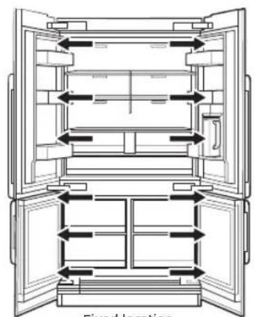
Fixed location
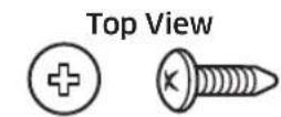
(TH) M4x16 12 ea
11. Attaching the Cabinet Trim
- Cabinet-side trim: Attach the trim between the refrigerator and the cabinet.
Cabinet Depth : 25" Cabinet Depth : 24"
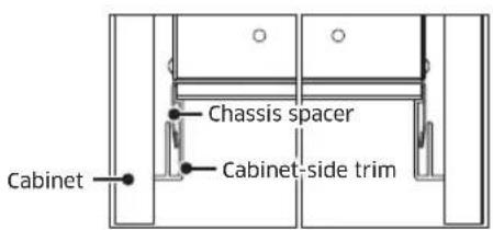

Installation instructions
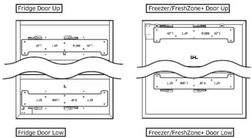
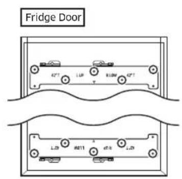
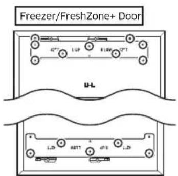
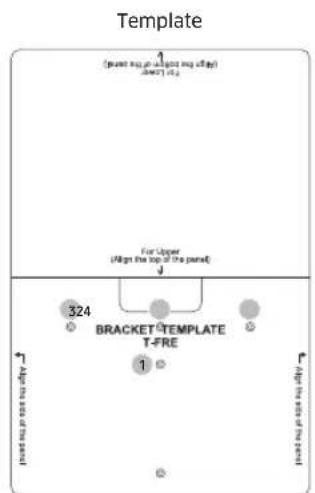
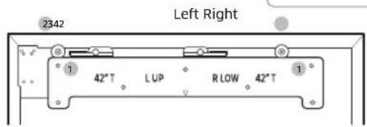
12. Attaching Panel brackets
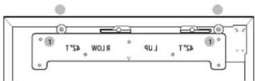
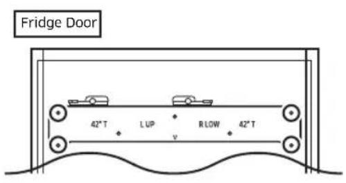
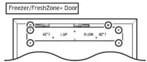
Attach the panel brackets to the top and bottom of the panel.
Custom Panel: STS
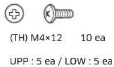
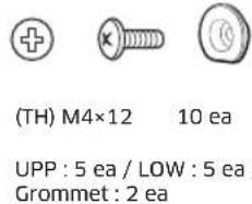
Drive 10 screws each to the top and bottom brackets as shown in the graphic. (The other holes on each side of the bracket are for a different application.)

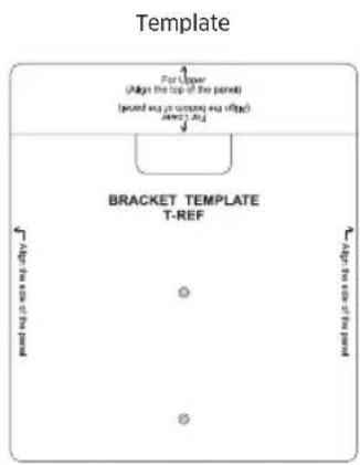
Custom Panel : Wood, Other
- The template informs you the position of the bracket and holes.
- Mark hole positions on every corner of the panel according to the template and drive the screws into the holes.
flowchart
graph TD
    A["Template"] --> B["1 (point sum, plus point sum of page)"]
    B --> C["324"]
    C --> D["BRACKET TEMPLATE T-FRE"]
    D --> E["1"]
    E --> F["for upper"]
    style A fill:#f9f,stroke:#333
    style B fill:#ccf,stroke:#333
    style C fill:#cfc,stroke:#333
    style D fill:#fcc,stroke:#333
    style E fill:#cff,stroke:#333
    style F fill:#ffc,stroke:#333
Installation instructions
Custom Panel: Recessed Back, Other
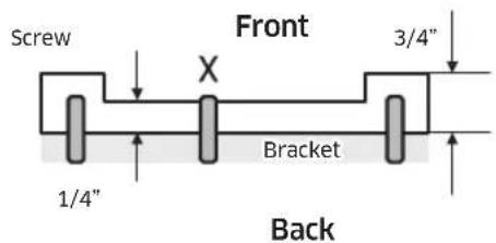
If, by the nature of its design, screws cannot be inserted at the center of the bracket, use the whichever suitable screw holes on the sides of the bracket to attach the panel.
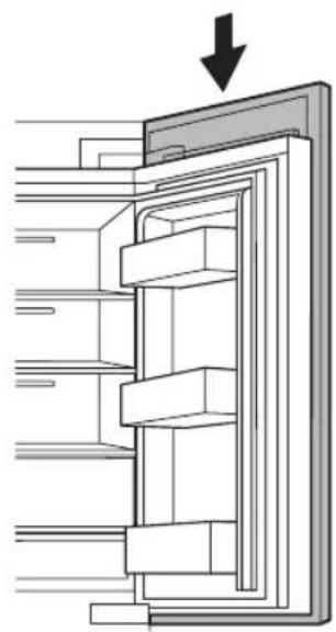
13. Hanging a Custom Panel

WARNING
If you install a custom panel before fixing the appliance to the cabinet, the custom panel can tip over. To prevent this, you must follow the installation instructions.
- Hang the panel bracket on the height adjustment screw. (See the graphic.)
natural_image
Diagram of a refrigerator interior showing internal shelves and door frame, with a downward arrow indicating direction (no text or symbols)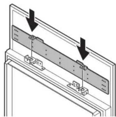
natural_image
Technical diagram of a mechanical assembly with two arrows indicating direction of movement or assembly (no text or symbols present)Installation instructions
14. Aligning the Panel
NOTE
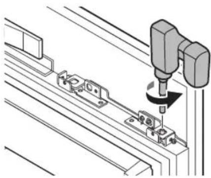
Each custom panel comes with 12 dedicated screws for fine-tuning. Use a minimum number of screws to fine-tune the custom panel with the cabinet. Once fine-tuning is complete, fix the custom panel with the top nut.
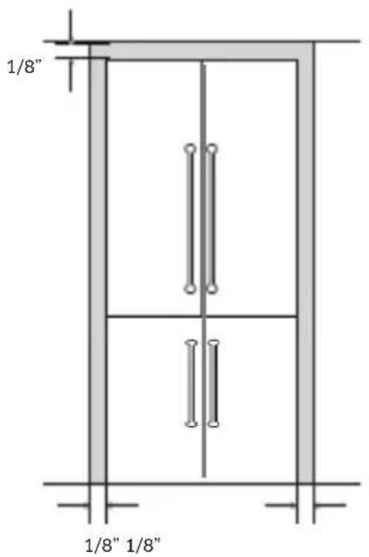
There are two panel-adjustment mechanisms at the top and two at the bottom of the door. Adjust the panel so it aligns with the surrounding cabinetry.
The gap between the cabinet and the panel must be:
- 1/8" (3 mm) on top
• 1/8" (3 mm) on the side
Top of the Door
- Use the double-threaded bolts to align the door panel.
- Engage a side screw (see the graphic) to shift the panel side to side.
- Engage Screw 1 (see the graphic) to shift the panel forward/backward; engage Screw 2 to set the panel in place.
English42-
- Engage Double Threaded Bolt (see the graphic) to shift the panel up and down.
- Engage a side screw (see the graphic) to shift the panel side to side.
- Engage Screw (backward) (see the graphic) to shift the panel forward/backward; engage Screw (forward) to set the panel in place.
Panel-adjustment mechanisms
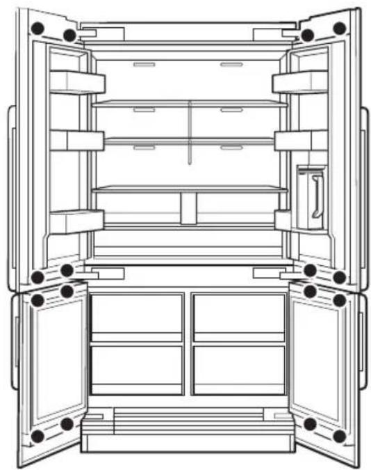
natural_image
Line drawing of an open refrigerator with doors open and shelves inside (no text or symbols)Each 12 screws per Door


M6x12 12 ea
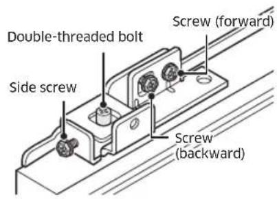
Panel-Adjustment Mechanism
Installation instructions
Top of Door
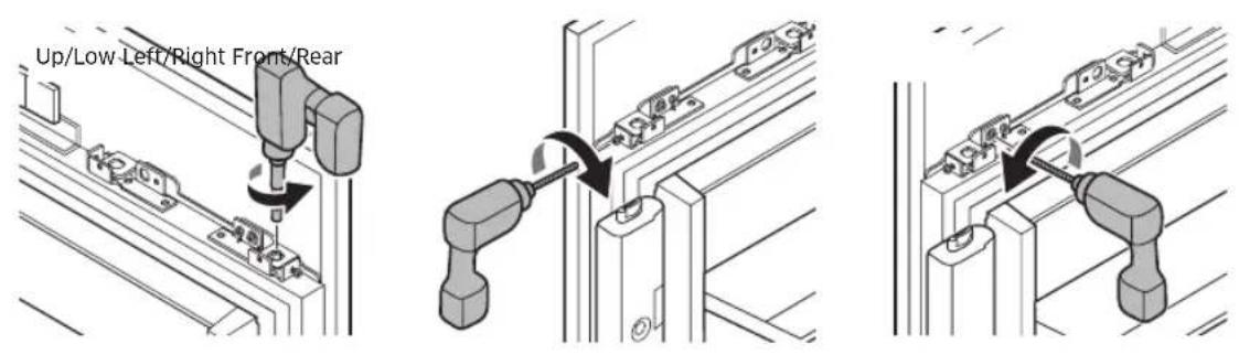
Bottom of Door
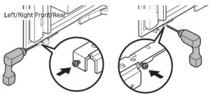
Attaching the Panel to the Door
Screw nuts snugly onto the double-threaded bolts.
natural_image
Technical line drawing of a mechanical assembly with a 3D tool inserted, showing no text or symbols.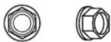
M13 8 ea
Two nuts per set
English44
15. Attaching the Door's Interior Covers
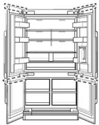
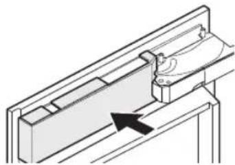
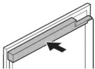
1. Upper Door Cover
- Connect housing connectors to separate Upper Door Cover. (Fridge Left and Right Door)
- Atattach the wire cover. (Fridge Left and Right Door)
- Push to the arrow direction.
natural_image
Line drawing of an open refrigerator cabinet with doors open (no text or symbols)Fridge Door
natural_image
Technical line drawing of a mechanical assembly with an arrow indicating direction (no text or symbols)Freezer/FreshZone+ Door
natural_image
Pure diagram of a structural beam with an arrow indicating direction (no text or symbols)Installation instructions
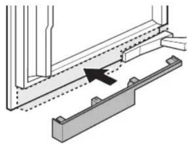
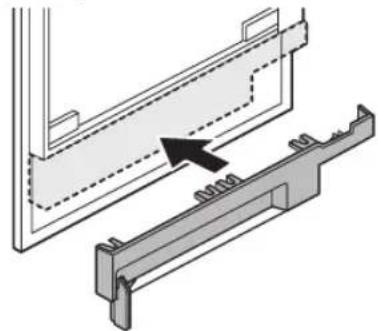
2. Lower Door Cover
Push to the arrow direction.

natural_image
Line drawing of an open refrigerator cabinet with doors open, showing internal compartments and doorways (no text or labels)Fridge Door
natural_image
Technical diagram showing a structural assembly with an arrow indicating direction (no text or symbols present)Freezer/FreshZone+ Door
natural_image
Technical diagram showing a mechanical assembly with a bracket and a directional arrow (no text or symbols)English46-
16. Connecting the Water Line
To prevent leaks and water damage, be careful not to kink the water line.
After connecting the water hose on the floor, open the water valve in the rear of the appliance and check the connection of the water supply line and make sure there is no leak.
There are several items you must purchase to complete this connection. You may find these items sold as a kit at your local hardware store.
| Copper Tubing | 1/4" copper tubing1/4" compression nut (1 pc)Ferrule (2 pc) |
| Plastic Tubing | 1/4" plastic tubing → Molded end (Bulb)1/4" compression nut (1 pc) |
- Remove the cap from the appliance connection.
- Bend the water line according to the location of the connection on the appliance.
- Slide the union nut and seal onto the water line.
- With the open-end wrench, tighten the union nut, being careful not overtighten.
- Open the shut-off valve and main water tap.
- Check the connection on the shut-off valve and on the appliance for leaks.
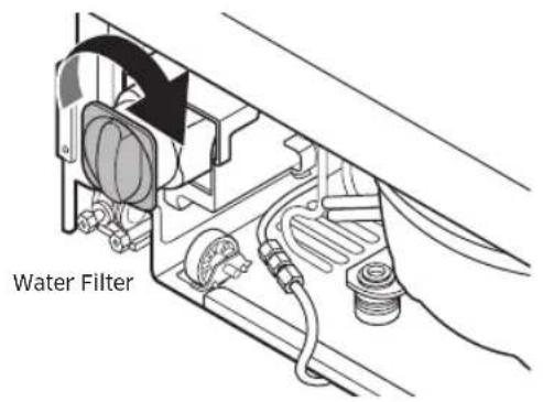
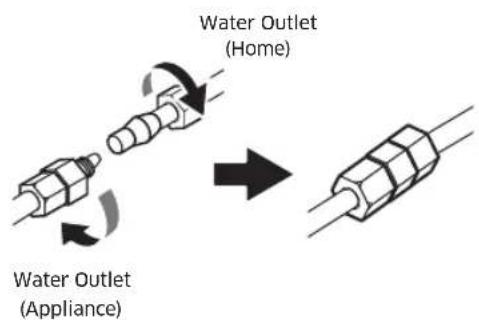
Installation instructions
17. Attaching kickplate and Toe kickplate
Attaching kickplate
- Drive the screws on both sides to attach the kickplate.
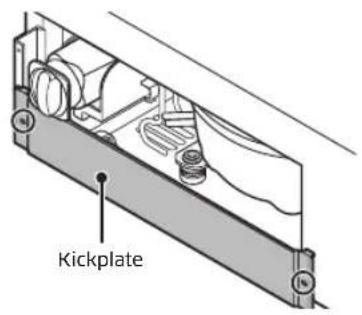
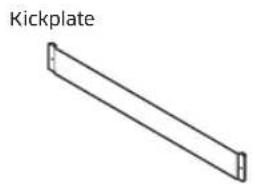
natural_image
Simple line drawing of a Kickplate with no text or symbolsM4x8 2 ea


Attaching Toe kickplate
- The height of the product can be adjusted between 83 3/8" \~ 84 3/8".
- If you want to use the provided Dacor toe kickplate (4"), note that it was designed for a product height of 83 7/8" and cabinet height of 84".
- If you want to use a toe kickplate not provided by Dacor, adjust the height of the toe kickplate accordingly.
- You can extend the bracket to move the kickplate by a max of 32 mm to the front. To extend the bracket, you must remove the grill cover first.
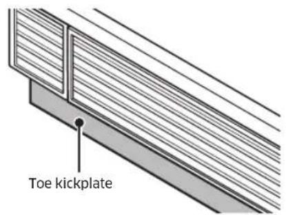
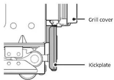
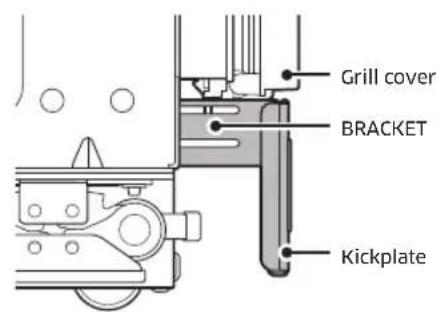
Factory default 32 mm to the front
English48-
18. Attaching the Door Trim
- Door side trim: Attach trim to the door side. Insert the door-side trim parallel with the top of the upper door cover.

WARNING
Please check again if there is any problem after installation.
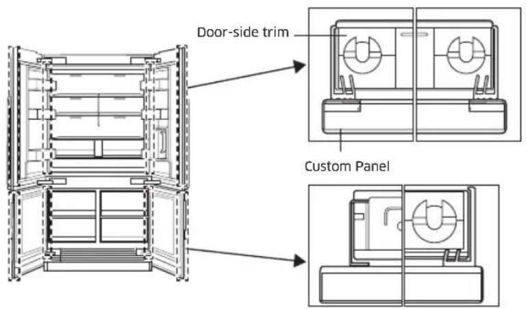
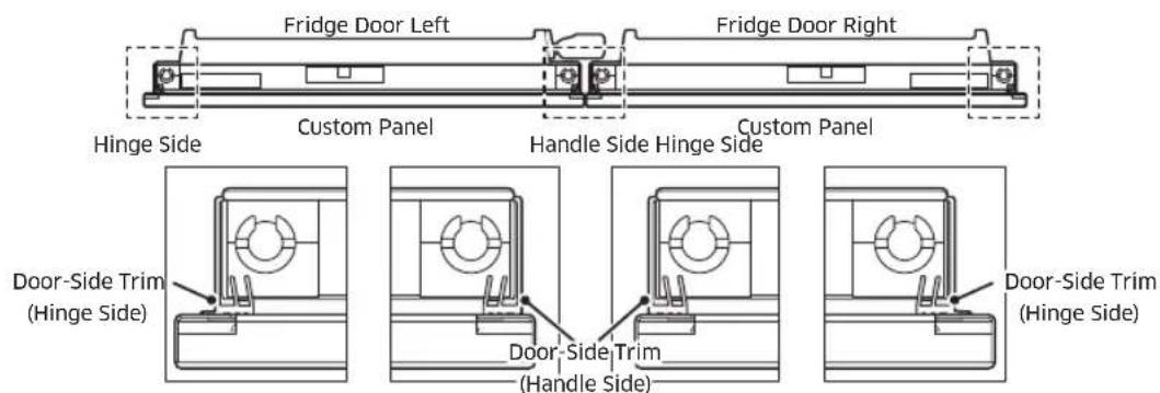
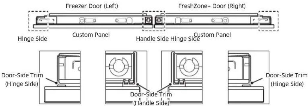
English
Installation instructions
19. Attaching Trim Top Cover
Attach the Trim Top Cover on the bottom of the Top Cover.
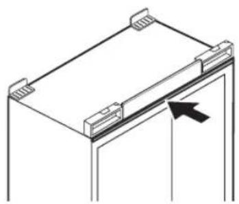
natural_image
Isometric line drawing of a mechanical component with a black arrow pointing to a section (no text or symbols)20. Removing the Interior packaging
Unpack EPS and tape.
21. Adjusting the door spring
Adjust the tension of the door spring according to the product size. With a star-head screwdriver, turn the adjusting screw.
I = maximum spring tension
0 = no spring tension
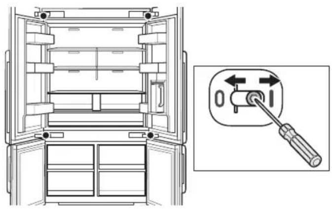
natural_image
Technical line drawing of an open refrigerator with a close-up inset showing the internal mechanism (no text or symbols)English50-
22. Cleaning
Remove protective vinyl and clean the custom panels.
23. Installation Checklist
Ensure the refrigerator functions properly and that the custom door panel aligns with the surrounding cabinetry.

WARNING
- The following checklist should be completed by the installer to ensure that the refrigerator is safely and correctly installed, functions properly, and that no part of the installation has been overlooked.
- Proper installation is the responsibility of the homeowner. The importance of proper installation of your Dacor appliance cannot be overemphasized.
Installation Checklist
☐ Has the unit been inspected for cosmetic damage?
☐ Has the water supply line been properly installed according to specifications and checked for leaks?
□ Is the unit properly aligned with the adjacent cabinets?
☐ Do all doors, drawers and shelves operate smoothly, without interference?
□ Has all packaging, tape, and literature been removed from inside and outside of the appliance?
☐ Is the power cable connected to a three-prong grounded electrical outlet that meets the electrical specifications?
□ Has the unit been properly leveled?
□ Has the anti-tip bracket been properly installed?
☐ Do all refrigerator components function properly?
□ Has the warranty been activated on-line or the warranty card filled out and mailed?


dacor
natural_image
Line drawing of an open refrigerator with doors open, showing internal compartments and storage areas (no text or symbols)Instalador
natural_image
Illustration of a plug with three outlets and a black arrow pointing to one outlet (no text or symbols)natural_image
Three identical black spikes on a horizontal line, no text or symbols presentRiesgo de explosión
natural_image
Simple line drawing of a two-decker cabinet with handles and a labeled dimension (no text or symbols)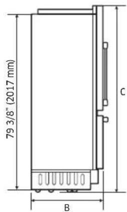
| Leyenda 48" | |
| A (Ancho) 47 3/4" (1213 mm) | |
| B (Profundidad) 25" (635 mm) | |
| C (Altura) 83 3/8" (2118 mm) | |
| D 47 1/4" (1200 mm) | |
| D1 (con panel) 49 11/16" (1262 mm) | |
| D2 (con manija contemporánea) 55 7/32" (1403 mm) | |
| E 51 1/2" (1308 mm) | |
| F 23 45/64" (602 mm) | |
| G 50 25/64" (1280 mm) |
natural_image
Illustration of a plug connecting to an electrical outlet with three outlets (no text or symbols)natural_image
Diagram of a structural beam with a highlighted rectangular component and an arrow indicating direction (no text or symbols)natural_image
Mechanical clamp or bracket assembly with a rod inserted, showing alignment lines and a black arrow indicating direction (no text or symbols)
natural_image
Technical line drawing of a mechanical component with two circular features and three vertical pins (no text or symbols)natural_image
Diagram of a refrigerator interior showing internal shelves and door frame, with a downward arrow indicating direction (no text or symbols)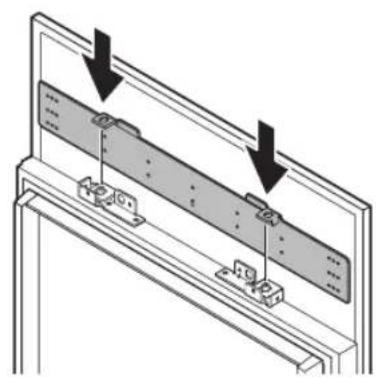
natural_image
Technical diagram of a mechanical assembly with two arrows indicating direction of movement or force (no text or symbols present)natural_image
Line drawing of an open refrigerator with doors open and shelves inside (no text or symbols)natural_image
Technical illustration of a CNC machining process with a tool and workpiece (no text or symbols)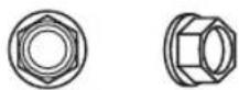
M13 8 uds.
natural_image
Line drawing of an open refrigerator with doors open, showing internal compartments and doorways (no text or labels)natural_image
Technical line drawing of a mechanical assembly with an arrow indicating direction (no text or symbols)natural_image
Pure diagram of a structural beam with an arrow indicating direction (no text or symbols)natural_image
Line drawing of an open refrigerator cabinet with doors open, showing internal compartments and doorways (no text or labels)natural_image
Technical diagram showing a structural assembly with an arrow indicating direction (no text or symbols present)natural_image
Technical diagram showing a mechanical assembly with a bracket and housing, no text or symbols presentEspañol46-
natural_image
Isometric line drawing of a mechanical component with a black arrow pointing to a section (no text or symbols)natural_image
Technical line drawing of an open refrigerator with a close-up inset showing the internal mechanism (no text or symbols)Español50-
22. Limpieza
natural_image
Line drawing of an open refrigerator with doors open, showing internal compartments and storage areas (no text or symbols)Installateur
natural_image
Illustration of a plug with three outlets connected to a wall socket (no text or symbols)natural_image
Three identical black spikes on a white background, no text or symbols presentRisque d'explosion
natural_image
Technical line drawing of a two-tier cabinet with vertical doors and handlebars, labeled 'A' at bottom (no text or symbols on the cabinet itself)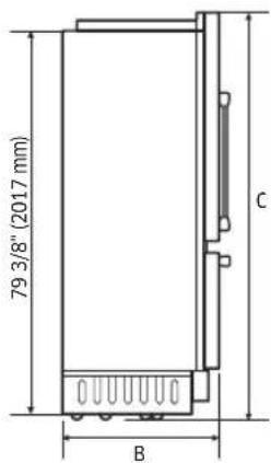
natural_image
Illustration of a plug connecting to an electrical outlet with three outlets (no text or symbols)NE COUPEZ ET NE RETIREZ JAMAIS LA TROISIÈME BROCHE (MISE À LA TERRE) DU CORDON D'ALIMENTATION.
N'UTILISEZ PAS UN ADAPTATEUR POUR BRANCHER LE RÉFRIGÉRATEUR À UNE PRISE 2 BROCHES.
N'UTILISEZ PAS DE RALLONGE AVEC CET APPAREIL.

AVERTISSEMENT
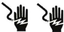
natural_image
Diagram of a structural beam with a highlighted rectangular component and an arrow indicating direction (no text or symbols)natural_image
Mechanical clamp or bracket assembly with a rod inserted, showing alignment lines and a black arrow pointing to a component (no text or symbols)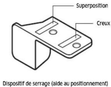
natural_image
Technical line drawing of a mechanical component with two circular features and internal shafts (no text or symbols)Avant Arrière
Arbre ajustable (10 mm)
Emplacement fixe
flowchart
graph TD
    A["pointing up and marking up off"] --> B["324"]
    C["for upper (from top of the panel)"] --> D["BRACKET TEMPLATE T-FRE"]
    E["1"] --> F["bracket up and mark up off"]
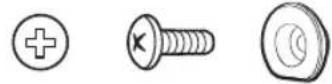
(TH) M4×12 10 pièce
natural_image
Diagram of a refrigerator interior showing internal shelves and door frame, with a downward arrow indicating direction (no text or symbols)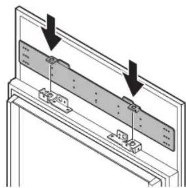
natural_image
Technical diagram of a mechanical assembly with two arrows indicating direction of movement or assembly (no text or symbols present)natural_image
Line drawing of an open refrigerator cabinet with doors open and shelves inside (no text or symbols)natural_image
Technical illustration of a CNC machining process with a 3D tool and workpiece (no text or symbols)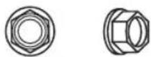
M13 8 pièce
natural_image
Pure diagram of a structural beam with an arrow indicating direction (no text or symbols)natural_image
Line drawing of an open refrigerator with doors open, showing internal shelves and compartments (no text or symbols)natural_image
Technical diagram showing a mechanical assembly with a bracket and a directional arrow (no text or symbols)natural_image
Technical diagram showing a mechanical assembly with a bracket and internal components, no text or symbols present.Français46
natural_image
Simple line drawing of a Plinthe rectangular beam (no text or symbols on the beam itself)M4x8 2 pièce


natural_image
Isometric line drawing of a mechanical component with a black arrow pointing to a section (no text or symbols)natural_image
Technical line drawing of an open refrigerator with a close-up inset showing the internal mechanism (no text or symbols)Français50-
22. Nettoyage

- Contents
- Before you begin... 4
- Important Safety Instructions 5
- Safety and warning information 10
- Installation Specifications 12
- Product Specifications 13
- Installation 17
- Installation requirements 18
- English2
- Installation instructions 26
- Before you begin...
- Important
- Installer
- User
- SAVE THESE INSTRUCTIONS
- Important Safety Instructions
- Safety symbols and labels
- DANGER
- WARNING
- CAUTION
- State of California Proposition 65 Warning
- ⚠ WARNING - R600a Refrigerant
- General Safety Precautions
- ! DANGER
- IMPORTANT:
- NOTE
- Safety and warning information
- Installation safety
- Location and installation safety
- Tip Hazard
- Explosion Risk
- Installation Specifications
- Product Specifications
- Custom Panel Specifications
- Handle Specifications
- Installation
- Appliance is very heavy :
- Installation room
- Stable installation
- Floor
- Aligning the appliance
- Installation requirements
- Installation preparation
- Cabinet installation parts
- Door installation parts
- Grounding the refrigerator
- Electric Shock Hazard
- Water-pressure requirements
- Connecting to the main water supply
- Cabinet special requirements
- Installation instructions
- Uncrating the Refrigerator
- Moving the Refrigerator
- Installation preparation
- Attaching the anti-tip-bracket
- Remove Upper & Lower Door Cover, Kickplate
- Attaching the Refrigerator's Top Cover
- Adjusting the door Opening Angle
- Moving the Refrigerator Into Its Enclosure
- Leveling the Refrigerator
- Securing the Refrigerator
- Attaching the Cabinet Trim
- Attaching Panel brackets
- Custom Panel: STS
- Custom Panel : Wood, Other
- Custom Panel: Recessed Back, Other
- Hanging a Custom Panel
- Aligning the Panel
- Top of the Door
- Attaching the Panel to the Door
- Attaching the Door's Interior Covers
- Upper Door Cover
- Lower Door Cover
- Connecting the Water Line
- Attaching kickplate and Toe kickplate
- Attaching kickplate
- Attaching Toe kickplate
- Attaching the Door Trim
- Attaching Trim Top Cover
- Removing the Interior packaging
- Adjusting the door spring
- Cleaning
- Installation Checklist
- Installation Checklist
- Instalador
- Riesgo de explosión
- Limpieza
- Installateur
- Risque d'explosion
- AVERTISSEMENT
- Nettoyage
Brand : Dacor
Model : RAT48AMAASR
Category : Refrigerator