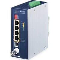
IVC-234GPT - Network Equipment Planet - Free user manual and instructions
Find the device manual for free IVC-234GPT Planet in PDF.


| Product Type | Industrial VDSL2 Extender with Gigabit PoE+ Switch |
| Brand | Planet |
| Model | IVC-234GPT |
| Network Ports | 4x 10/100/1000BASE-T RJ45 with PoE+ (802.3at), 1x VDSL2 BNC port, 1x VDSL2 RJ11 port |
| Power Input | DC 12-54V or AC 24V, dual redundant input with reverse polarity protection |
| Power Consumption | Max. 122 watts (at DC 54V with full PoE load) |
| Total PoE Budget | 60W (12V DC), 100W (24V DC), 120W (48-54V DC) |
| PoE Power per Port | Up to 30.8 watts (54V DC) |
| Dimensions (W × D × H) | 56 × 86.1 × 135 mm |
| Weight | 736 g |
| Housing Material | Metal IP30 |
| Operating Temperature | -40°C to 75°C |
| Operating Humidity | 5% to 95% (non-condensing) |
| VDSL2 Standards | ITU-T G.993.2 (Profile 17a/30a/35b), G.993.5 G.Vectoring, G.INP |
| Maximum VDSL2 Distance | Up to 1400 meters (depending on cable and settings) |
| Electrostatic Discharge (ESD) Protection | 6KV DC |
| DIP Switch Functions | Mode selection (CO/CPE), G.INP/Interleave, symmetric/asymmetric, SNR margin (8dB/12dB) |
| LED Indicators | Power (P1, P2, Alarm), VDSL (Link, CO, CPE), Link/Activity per port, PoE in use, PoE usage (30/60/90/120W) |
| Mounting | DIN rail, wall (kit included) |
| Package Contents | Extender, DIN rail mounting kit, wall mounting kit, RJ45/BNC/RJ11 protective caps, quick start guide |
Frequently Asked Questions - IVC-234GPT Planet
User questions about IVC-234GPT Planet
0 question about this device. Answer the ones you know or ask your own.
Ask a new question about this device
Download the instructions for your Network Equipment in PDF format for free! Find your manual IVC-234GPT - Planet and take your electronic device back in hand. On this page are published all the documents necessary for the use of your device. IVC-234GPT by Planet.
USER MANUAL IVC-234GPT Planet
Industrial 1-Port BNC/RJ11 to 4-Port Gigabit Ethernet Extender
IVC-234GT/IVC-234GPT
User's Manual
Table of Contents
- Package Contents 3
2.Hardware Introduction 5
2.1 Extender Front Panel 5
2.2 LED Definition 8
2.3 Extender Upper Panel 10
2.4 Wiring the Power Inputs 10
2.5 Wiring the Faulty Alarm Contact 12
2.6 Grounding the Device 12
2.7 Physical Dimensions 13
- Installation 15
3.1 DIN-rail Mounting Installation 15
3.2 Wall-mount Plate Mounting 16
3.3 Side Wall-mount Plate Mounting 16
- Product Specifications 17
- Performance Table 20
5.1 IVC-234GT(V2) 20
5.2 IVC-234GPT 22
- Customer Support 24
1. Package Contents
Thank you for purchasing PLANET Industrial 1-Port BNC/RJ11 to 4-Port Gigabit Ethernet Extender, IVC-234GT or IVC-234GPT. The tables below show the model descriptions and the number of ports:
| Model Name Model Description |
| IVC-234GT Industrial 1-Port BNC/RJ11 to 4-Port Gigabit Ethernet Extender |
| IVC-234GPT Industrial 4-Port 10/100/1000T 802.3at PoE+ to VDSL2 Extender |
| Model Name | VDSL2 BNC Port | VDSL2 RJ11 Port | 10/100/1000T Copper Ports | 802.3at PoE Ports |
| IVC-234GT 1 1 4 - | ||||
| IVC-234GPT 1 1 4 4 | 4 4 |
In the following sections, the term "Industrial Ethernet Extender" means the IVC-234GT or IVC-234GPT.
Open the box of the Industrial Ethernet Extender and carefully unpack it. The box should contain the following items:
| Industrial Ethernet Extender x 1 | QR Code Sheet x 1 RJ45 | Dust Cap x 4 |
| IVC-234GT IVC-234GPT | ||
| BNC Dust Cap x 1/RJ11 Dust Cap x 1 Wall-mount Kit | ||
| BNC Dust Cap | RJ11 Dust Cap | IVC-234GT |
| DIN-rail Kit Wall-mount Kit | ||
| IVC-234GT | IVC-234GPT | IVC-234GPT |
If any of these are missing or damaged, please contact your dealer immediately; if possible, retain the carton including the original packing material, and use them again to repack the product in case there is a need to return it to us for repair.
2. Hardware Introduction
2.1 Extender Front Panel
The front panel of the Industrial Ethernet Extender consists of Ethernet, VDSL2 interfaces and LED indicators.
■ Front View

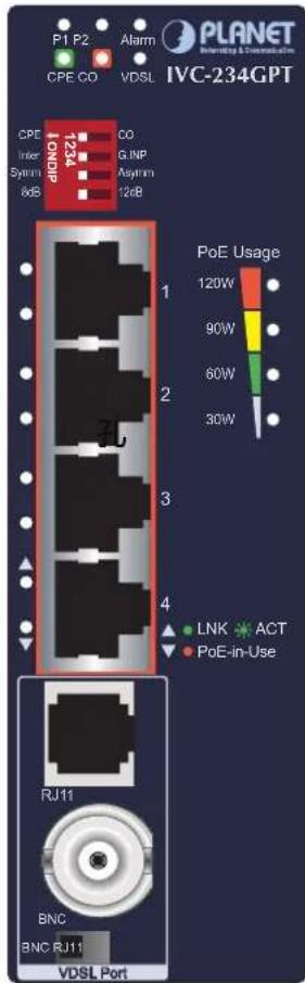
Figure 1: IVC-234GT/IVC-234GPT Front View
IVC-234GT Ethernet Interfaces
Gigabit Ethernet TP interfaces (Port 1 to port 4)
10/100/1000BASE-T copper, RJ45 twisted-pair: Up to 100 meters.
IVC-234GPT Ethernet Interfaces
Gigabit Ethernet 802.3at PoE+ TP interfaces (Port 1 to port 4)
10/100/1000BASE-T copper, RJ45 twisted-pair: Up to 100 meters.
IVC-234GT/IVC-234GPT VDSL2 Interfaces
One RJ11 female phone jack and one BNC female connector for VDSL2 with the VDSL2 Super Vector 35b profile.
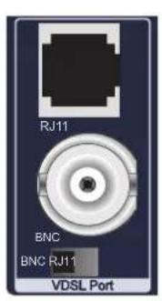
VDSL Port BNC/RJ11 DIP Switch
One DIP switch for RJ11 female phone jack and one BNC female connector for better VDSL2 transmission performance.
| Mode | DIP Switch |
| Description | |
| RJ11 | Choose this mode when using RJ11 VDSL2 transmission for better performance. |
| BNC (Default) | Choose this mode when using BNC VDSL2 transmission for better performance. |
VDSL DIP Switch
The Industrial Ethernet Extender provides 4 selective transmission modes. By switching to a transmission mode, it can optimize transmission based on the quality and distance of your coaxial cable or phone line. The following is the summary table of transmission setting, bandwidth and distance.
| DIP-1 DIP-2 DIP-3 DIP-4 | ||||
| Mode Transmission Band Profile | SNR Margin | |||
| OFF CO G.INP Asymmetric 12dB | ||||
| ON (Default) | CPE | Interleave | Symmetric | 8dB |
> DIP-1: Mode (CO/CPE)

Note
By default, the four DIP switches, set at the "ON" position, are operated as "CPE". For operating as "CO", please turn DIP 1 Switch to the "OFF" position. Then adjust the other DIP switches accordingly to fulfill different network application demands.
CO
(Central Office)
The Master device mode, usually the CO device, is located at the data center of ISP or enterprise to link to the backbone.
CPE
(Customer
Premises
Equipment)
The Slave device mode, usually the CPE device, is located at a branch office or remote side as the long reach data receiver. The CPE can be connected to the PC, IP camera or wireless access point or other network devices.

Note
When the Industrial Ethernet Extender operates in CPE mode, DIP switches 2, 3, and 4 are out of function.
DIP-2: Transmission (G. INP and Interleave mode)
| G. INP | Method of protection against bursts from other devices or lines to impact your xDSL line. |
| Interleave | Method of error correction used on xDSL line. Interleave requires additional latency to improve resilience to burst of error. |
> DIP-3: Band Profile (Asymmetric/Symmetric)
| Asymmetric | Asymmetric mode provides more bandwidth than the other side. This mode provides the highest bandwidth in short range. |
| Symmetric | With G.997 band plan supported, symmetric mode can provide almost the same rate of downstream and upstream. |
DIP-4:SNR (Signal Noise Ratio) Margin
When the SNR margin is selected, the system provides 12dB/8dB SNR margin for all usable loop lengths. Better channel noise protection is made with the higher SNR margin.

Please power off the Industrial Ethernet Extender before making any transmission mode adjustment.
PoE Power Usage LED (IVC-234GPT Only)
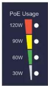
The front panel of the IVC-234GPT has four Gigabit Ethernet 802.3at PoE+ ports, and four LEDs which indicate PoE Power Usages of 30W, 60W, 90W and 120W. With these LED indications, you can monitor the current PoE power-in-use status of the IVC-234GPT easily and efficiently.
2.2 LED Definition
System
| LED Color Function | ||
| P1 Green Lights to indicate DC power input 1 has power. | ||
| P2 Green Lights to indicate DC power input 2 has power. | ||
| Alarm Red Lights to indicate that DC power has failed. |
VDSL
| LED | Color Function | ||
| VDSL | Green | Lit | Lights to indicate the port is running at 10/100Mbps and successfully established. |
| Fast Blink | Indicates that the VDSL connection is in training status. | ||
| Off | Indicates that the VDSL connection is in idle status. | ||
| CO | Green Lit | Indicates the Industrial Ethernet Extender is running in CO mode. | |
| CPE | Green Lit | Indicates the Industrial Ethernet Extender is running in CPE mode. | |
10/100/1000BASE-T Port (IVC-234GT only)
| LED Color Function | |||
| LNK/ACT | Green | Lit | Indicates that the port is operating at 1000Mbps, 100Mbps or 10Mbps. |
| Blink | Indicates that the Industrial Ethernet Extender is actively sending or receiving data over that port. | ||
| Off | Indicates that the port is link down. | ||
10/100/1000BASE-T 802.3at PoE+ Port (IVC-234GPT only)
| LED Color Function | |||
| LNK/ACT | Green | Lit | Indicates that the port is operating at 1000Mbps, 100Mbps or 10Mbps. |
| Blink | Indicates that the Industrial Ethernet Extender is actively sending or receiving data over that port. | ||
| Off | Indicates that the port is link down. | ||
| PoE-in-use | Amber | Lit | Indicates the port is providing DC in-line power. |
| Off | Indicates the connected device is not a PoE powered device (PD). | ||
■ PoE Power Usage (Unit: Watt) (Lower LED to Upper LED) (IVC-234GPT only)
| LED Color Function | |
| 30W Amber | Off to indicate the PoE usage is less than 14W. Blinks to indicate that the PoE usage is around 15W to 30W. Lights to indicate the PoE usage is around/over 30W. |
| 60W Amber | Blinks to indicate that the PoE usage is around 45W to 60W. Lights to indicate the PoE usage is around/over 60W. |
| 90W Amber | Blinks to indicate that the PoE usage is around 75W to 90W. Lights to indicate the PoE usage is around/over 90W. |
| 120W Amber | Blinks to indicate that the PoE usage is around 100W to 120W. Lights to indicate the PoE usage is at the maximum 120W. |
2.3 Extender Upper Panel
The upper panel of the Industrial Ethernet Extender consists of one terminal block connector within two DC power inputs. Figures 2 and 3 show the upper panels of the Industrial Ethernet Extender.
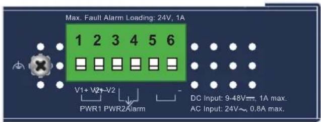
Figure 2: IVC-234GT Upper Panel
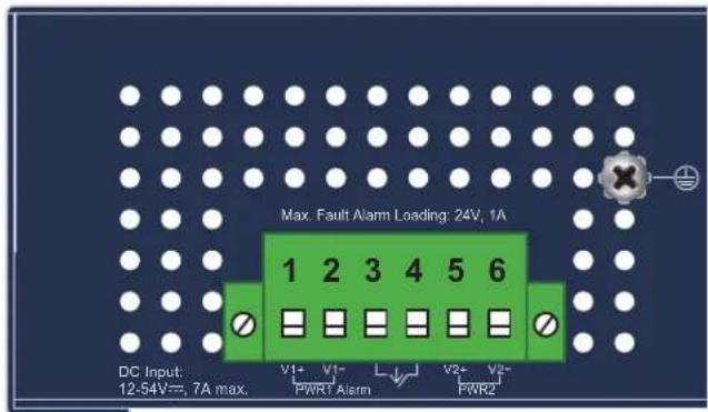
Figure 3: IVC-234GPT Upper Panel
2.4 Wiring the Power Inputs
The 6-contact terminal block connector on the top panel of Industrial Ethernet Extender is used for two redundant power inputs. Please follow the steps below to insert the power wire.

Caution
When performing any of the procedures like inserting the wires or tightening the wire-clamp screws, make sure the power is OFF to prevent from getting an electric shock.
- Insert positive and negative DC power wires into contacts 1 and 2 for POWER 1, or contacts 5 and 6 for POWER 2.
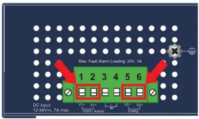
| V1+ V1- V2+ V2- | |
| PWR1 PWR2 | |
- Tighten the wire-clamp screws for preventing the wires from loosening.
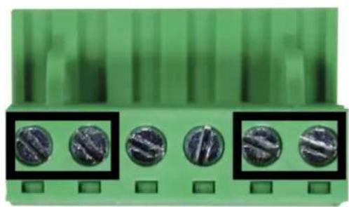
123456
Power 1 Alarm Power 2
V+V-V+V-

Caution
- PWR1 and PWR2 must provide the same DC voltage for power load balance while operating with dual power input.
- IVC-234GT use one power input when using 24V AC.
2.5 Wiring the Faulty Alarm Contact
The faulty alarm contacts are in the middle of the terminal block connector as the picture shows below. Inserting the wires, the Industrial Ethernet Extender will detect the fault status of the power failure and then forms an open circuit. The following illustration shows an application example for wiring the faulty alarm contacts.
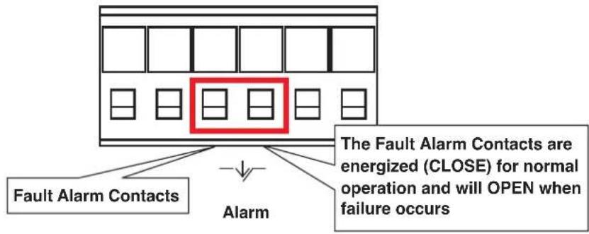
Insert the wires into the fault alarm contacts

Note
- The wire gauge for the terminal block should be in the range of 12 24AWG .
- Alarm relay circuit accepts up to 24V, max. 1A currents.
2.6 Grounding the Device
Users MUST complete grounding wired with the device; otherwise, a sudden lightning could cause fatal damage to the device.
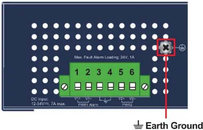

Note
EMD (Lightning) DAMAGE IS NOT COVERED UNDER WARRANTY.
2.7 Physical Dimensions
IVC-234GT Dimensions (W x D x H): 32 x 87.8 x 135mm
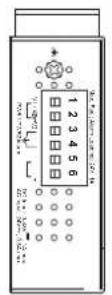
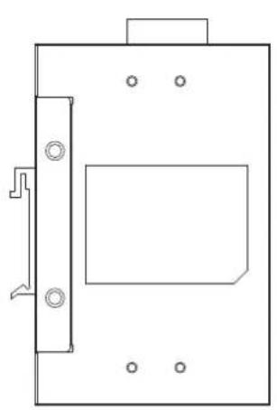
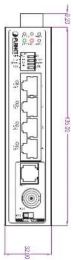
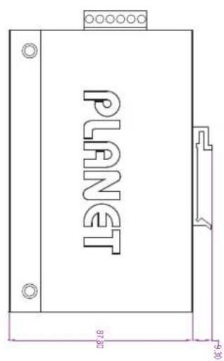
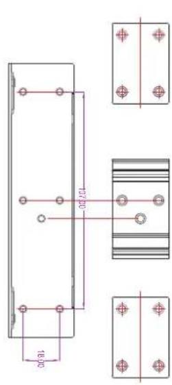
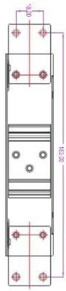
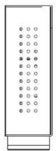
Dimensions (W× D× H):32× 87.8× 135mm
IVC-234GPT Dimensions (W x D x H): 56 x 86.1 x 135mm
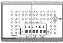
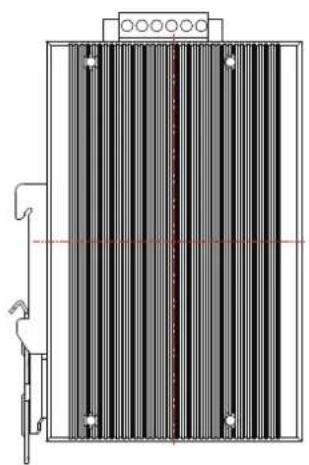
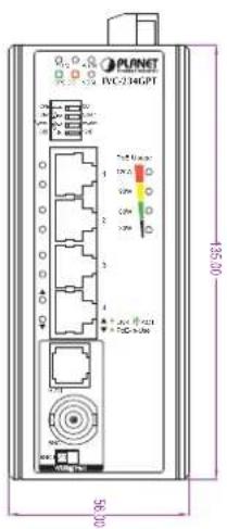
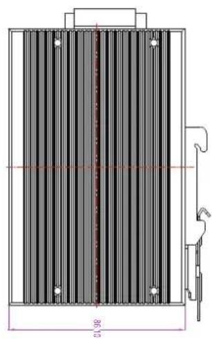
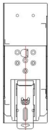
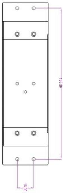

Dimensions (W x D x H): 56 x 86.1 x 135 mm
3. Installation
This section describes the functionalities of the Industrial Ethernet Extender's components and guides you to installing it on the DIN rail and wall. Please read this chapter completely before continuing.

Note
The following pictures show how to install the device. However, the device in the picture is not Industrial Ethernet Extender.
3.1 DIN-rail Mounting Installation
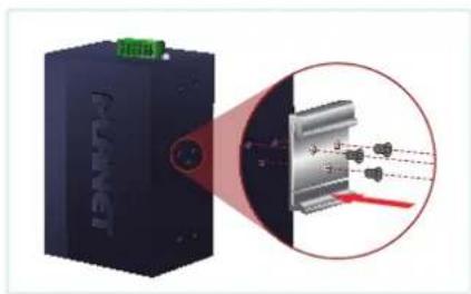
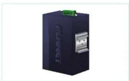
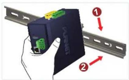
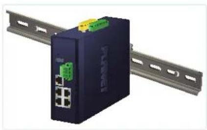
IVC-234GT DIN-rail Mounting Installation
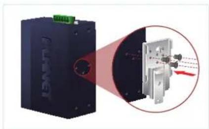
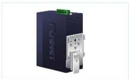
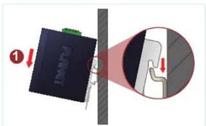
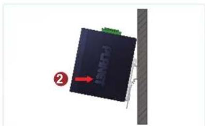
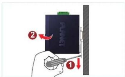
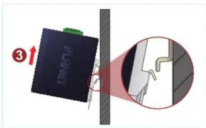
IVC-234GPT DIN-rail Mounting Installation
3.2 Wall-mount Plate Mounting
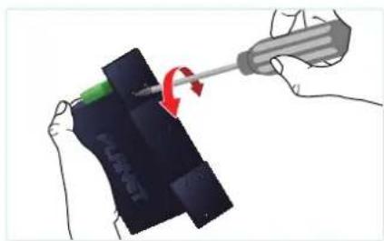
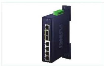
3.3 Side Wall-mount Plate Mounting

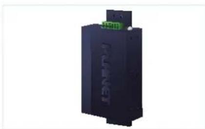

Caution
You must use the screws supplied with the wall-mounting brackets. Damage caused to the parts by using incorrect screws would invalidate your warranty.
4. Product Specifications
This section describes the functionalities of the Industrial Ethernet Extender's components and guides you to installing the Industrial Ethernet Extender.
| Product IVC-234GT IVC-234GPT | ||
| Hardware Specifications | ||
| Hardware Version 2 1 | ||
| LAN Ports 4 10/100/1000BASE-T RJ45 auto-MDI/MDI-X ports | ||
| 802.3at PoE Ports NA 4 | ||
| VDSL Port | BNC | 1 BNC female Ethernet over Coaxial port |
| Coaxial cable: 75 ohmRG-6/U cable, less than 12Ω/1000 ft.RG-59/U cable, less than 30Ω/1000 ft. | ||
| Max. 1400m with data transmission (4,593ft.) | ||
| RJ11 | 1 VDSL2 RJ11 female phone jack | |
| Twisted-pair telephone wires (AWG-24 or better) | ||
| Max. 1400m with data transmission (4,593ft.) | ||
| DIP Switch & Functionality | DIP-1 Select CO or CPE mode. | |
| DIP-2 Select G.INP or Interleaved mode. | ||
| DIP-3 Select Band Profile (Asymmetric or Symmetric). | ||
| DIP-4 Select SNR of 12dB or 8dB. | ||
| ESD Protection 6KV DC | ||
| Dimensions(W × D × H) | 32 × 87.8 × 135mm 56 × 86.1 x 135mm | |
| Weight | 452g 736g | |
| Power Requirements | DC 9~48V or AC 24VRedundant power with reverse polarity protection DC 9V: 3.96 watts/13.5BTUDC 48V: 3.36 watts/11.4BTUAC 24V: 4.1 watts/13.9BTU DC 12V: 60 watts/204BTUDC 24V: 100 watts/341BTUDC 54V: 122 watts/416BTU | |
| Power Consumption | ||
| LED Indicators | 3 x LED for System and Power: ■ Green: DC Power 1 ■ Green: DC Power 2 ■ Red: Alarm 3 x LED for VDSL2 interface: ■ Green: VDSL ■ Green: CO ■ Green: CPE 2 x LED for Per Copper Port (Port-1~Port-4): ■ Green: 10/100/1000 LNK/ACT ■ Amber PoE-in-Use (IVC-234GPT only) 4 x LED for PoE Usage: (IVC-234GPT only) ■ Amber 30W ■ Amber 60W ■ Amber 90W ■ Amber 120W | |
| Housing IP30 Metal Case | ||
| Power over Ethernet Specifications (IVC-234GPT only) | ||
| PoE Standard | IEEE 802.3af PoE PSE IEEE 802.3at PoE+ PSE | |
| PoE Power Supply Type | End-span | |
| Power PIN Assignment | 1/2(+), 3/6(-) | |
| PoE Power Output Per | port 54V DC, Max. 30.8 watts | |
| PoE Power Output Budget | DC 12V, 60 watts maximum DC 24V, 100 watts maximum DC 48-54V, 120 watts maximum | |
| Switch Specifications | ||
| Switch Processing Scheme | Store-and-Forward | |
| Address Table 1K entries | ||
| Maximum Packet Size | 1522bytes | |
| Standards Conformance | ||
| VDSL Compliance | ■ VDSL-DMT ■ ITU-T G.993.1 VDSL ■ ITU-T G.997.1 ■ ITU-T G.993.2 VDSL2 (Profile 17a/30a/35b support) ■ ITU-T G.993.5 G.vectororing ■ ITU-T G.998 ■ G.INP | |
| ADSL Compliance | ■ Capable of ADSL2/2+ standard ■ ITU G.992.3 G.dmt.bis ■ ITU G.992.5 G.dmt.bisplus ■ Data Rate: Up to 24Mbps | |
| Standards Compliance | IEEE 802.3 Ethernet IEEE 802.3u Fast Ethernet IEEE 802.3ab Gigabit Ethernet IEEE 802.1p Class of Service ITU-T G.993.1 VDSL ITU-T G.997.1 ITU-T G.993.2 VDSL2 (Profile 17a/30a/35b support) ITU-T G.993.5 G.Vectoring & G.INP ITU-T G.998 | |
| Regulatory Compliance | FCC Part 15 Class A, CE | |
| Environment | ||
| Temperature | Operating: -40~75 degrees C Storage: -40~75 degrees C | |
| Humidity | Operating: 5~95% (non-condensing) Storage: 5~95% (non-condensing) | |
5. Performance Table
5.1 IVC-234GT(V2)
| RJ11 Performance* | ||||
| Distance (meter) | Interleave (Downstream/Upstream: Mbps) | |||
| Asymmetric Symmetric | ||||
| 8dB 12dB | 8dB 12dB | |||
| 200m 253/56 | 260/53 | 181/173 | 172/164 | |
| 400m 229/52 | 200/51 | 147/140 | 136/123 | |
| 600m 112/42 | 99/39 | 95/78 | 77/64 | |
| 800m 108/33 | 77/28 | 72/51 | 59/40 | |
| 1000m 71/15 | 60/12 | 51/27 | 47/24 | |
| 1200m 43/9 | 35/6 | 29/25 | 24/20 | |
| 1400m 26/7 | 23/6 | 19/13 | 18/11 | |
| Distance (meter) | G.INP (Downstream/Upstream: Mbps) | |||
| Asymmetric Symmetric | ||||
| 8dB 12dB | 8dB 12dB | |||
| 200m 308/55 | 285/53 | 191/186 | 183/175 | |
| 400m 246/55 | 211/52 | 143/141 | 140/124 | |
| 600m 125/43 | 96/40 | 88/81 | 99/39 | |
| 800m 108/33 | 77/28 | 72/51 | 59/40 | |
| 1000m 71/15 | 60/12 | 51/27 | 47/24 | |
| 1200m 43/9 | 35/6 | 29/25 | 24/20 | |
| Coaxial Performance* | ||||
| Distance (meter) | Interleave (Downstream/Upstream: Mbps) | |||
| Asymmetric Symmetric | ||||
| 8dB 12dB | 8dB 12dB | |||
| 200m 258/53 | 256/51 | 178/177 | 173/170 | |
| 400m 252/51 | 238/50 | 152/151 | 145/143 | |
| 600m 205/48 | 189/47 | 125/124 | 115/114 | |
| 800m 166/47 | 141/46 | 108/101 | 91/89 | |
| 1000m 121/45 | 96/39 | 81/79 | 71/70 | |
| 1200m 83/38 | 63/34 | 62/60 | 54/51 | |
| 1400m 32/21 | 30/19 | 28/25 | 18/15 | |
| Distance (meter) | G.INP (Downstream/Upstream: Mbps) | |||
| Asymmetric Symmetric | ||||
| 8dB 12dB | 8dB 12dB | |||
| 200m 316/56 | 299/55 | 183/181 | 179/178 | |
| 400m 276/52 | 246/50 | 167/165 | 157/152 | |
| 600m 218/50 | 196/49 | 136/129 | 124/114 | |
| 800m 171/49 | 145/57 | 108/103 | 96/92 | |
| 1000m 122/48 | 97/41 | 83/81 | 72/71 | |
| 1200m 86/42 | 69/36 | 69/64 | 55/53 | |
| 1400m 46/26 | 37/21 | 39/31 | 31/23 | |
| * As there are various resistance values in the category of RG-59/U or RG-6/U cable, the actual data rate will vary on the quality of the copper wire and environmental factors. | ||||
5.2 IVC-234GPT
| RJ11 Performance* | ||||
| Distance (meter) | Interleave (Downstream/Upstream: Mbps) | |||
| Asymmetric Symmetric | ||||
| 8dB 12dB | 8dB 12dB | |||
| 200m 264/57 | 255/56 | 174/171 | 165/159 | |
| 400m 212/53 | 182/49 | 140/131 | 125/114 | |
| 600m 117/44 | 95/39 | 80/78 | 66/66 | |
| 800m 92/32 | 76/25 | 66/52 | 55/40 | |
| 1000m 40/29 | 33/19 | 42/29 | 33/25 | |
| 1200m 30/19 | 33/19 | 28/27 | 26/18 | |
| 1400m 29/11 | 25/7 | 29/11 | 21/12 | |
| Distance (meter) | G.INP (Downstream/Upstream: Mbps) | |||
| Asymmetric Symmetric | ||||
| 8dB 12dB | 8dB 12dB | |||
| 200m 306/60 | 279/58 | 186/186 | 174/171 | |
| 400m 221/57 | 192/52 | 146/134 | 129/116 | |
| 600m 118/45 | 95/40 | 81/80 | 62/54 | |
| 800m 92/33 | 77/28 | 65/51 | 54/42 | |
| 1000m 39/22 | 32/17 | 42/42 | 35/25 | |
| 1200m 30/21 | 25/16 | 32/22 | 26/19 | |
| 1400m 28/12 | 24/9 | 25/16 | 21/12 | |
| * The performance data above is for reference only. The actual data rate will vary on the quality of the copper wire and environmental factors. | ||||
| Coaxial Performance* | ||||
| Distance (meter) | Interleave (Downstream/Upstream: Mbps) | |||
| Asymmetric Symmetric | ||||
| 8dB 12dB | 8dB 12dB | |||
| 200m 264/57 | 255/56 | 177/172 | 168/164 | |
| 400m 256/56 | 213/55 | 153/150 | 143/141 | |
| 600m 184/56 | 159/51 | 129/117 | 111/105 | |
| 800m 144/52 | 121/47 | 101/96 | 87/86 | |
| 1000m 94/44 | 84/39 | 79/75 | 68/63 | |
| 1200m 77/37 | 63/32 | 60/60 | 50/49 | |
| 1400m 32/21 | 30/19 | 28/25 | 18/15 | |
| Distance (meter) | G.INP (Downstream/Upstream: Mbps) | |||
| Asymmetric Symmetric | ||||
| 8dB 12dB | 8dB 12dB | |||
| 200m 302/60 | 277/59 | 187/182 | 176/171 | |
| 400m 249/58 | 252/59 | 163/156 | 149/142 | |
| 600m 191/58 | 167/56 | 133/121 | 118/107 | |
| 800m 191/58 | 121/50 | 103/97 | 92/88 | |
| 1000m 97/49 | 83/40 | 82/70 | 71/60 | |
| 1200m 77/37 | 63/32 | 63/56 | 50/49 | |
| 1400m 46/26 | 37/21 | 39/31 | 31/23 | |
| * As there are various resistance values in the category of RG-59/U or RG-6/U cable, the actual data rate will vary on the quality of the copper wire and environmental factors. | ||||
6. Customer Support
Thank you for purchasing PLANET products. You can browse our online FAQ resource on PLANET web site first to check if it could solve your issue. If yc support information, please contact PLANET switch support team.
PLANET online FAQs:
https://www.planet.com.tw/en/support/faq
Switch support team mail address: support@planet.com.tw
Copyright © PLANET Technology Corp. 2025.
Contents are subject to revision without prior notice.
PLANET is a registered trademark of PLANET Technology Corp.
All other trademarks belong to their respective owners.
FCC Warning
This equipment has been tested and found to comply with the regulations for a Class A digital device, pursuant to Part 15 of the FCC Rules. These limits are designed to provide reasonable protection against harmful interference when the equipment is operated in a commercial environment. This equipment generates, uses, and can radiate radio frequency energy and, if not installed and used in accordance with this user's guide, may cause harmful interference to radio communications. Operation of this equipment in a residential area is likely to cause harmful interference, in which case the user will be required to correct the interference at his own expense.
CE Mark Warning
This device is compliant with Class A of CISPR 32. In a residential environment this equipment may cause radio interference.
WEEE Warning

To avoid the potential effects on the environment and human heresult of the presence of hazardous substances in electrical and electronic equipment, end users of electrical and electronic equipment should understand the meaning of the crossed-out wheeled bin symbol. Do not
dispose of WEEE as unsorted municipal waste and have to collect such WEEE separately.
- Industrial 1-Port BNC/RJ11 to 4-Port Gigabit Ethernet Extender
- Table of Contents
- Package Contents
- Hardware Introduction
- Extender Front Panel
- ■ Front View
- IVC-234GT Ethernet Interfaces
- Gigabit Ethernet TP interfaces (Port 1 to port 4)
- IVC-234GPT Ethernet Interfaces
- Gigabit Ethernet 802.3at PoE+ TP interfaces (Port 1 to port 4)
- IVC-234GT/IVC-234GPT VDSL2 Interfaces
- VDSL Port BNC/RJ11 DIP Switch
- VDSL DIP Switch
- > DIP-1: Mode (CO/CPE)
- DIP-2: Transmission (G. INP and Interleave mode)
- > DIP-3: Band Profile (Asymmetric/Symmetric)
- DIP-4:SNR (Signal Noise Ratio) Margin
- PoE Power Usage LED (IVC-234GPT Only)
- LED Definition
- Extender Upper Panel
- Wiring the Power Inputs
- Wiring the Faulty Alarm Contact
- Grounding the Device
- Physical Dimensions
- Installation
- DIN-rail Mounting Installation
- Wall-mount Plate Mounting
- Side Wall-mount Plate Mounting
- Product Specifications
- Performance Table
- IVC-234GT(V2)
- IVC-234GPT
- Customer Support
- FCC Warning
- CE Mark Warning
- WEEE Warning
Brand : Planet
Model : IVC-234GPT
Category : Network Equipment