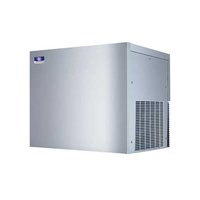
RFP0320A - Ice machine Manitowoc - Free user manual and instructions
Find the device manual for free RFP0320A Manitowoc in PDF.


| Product Type | Modular Flake Ice Machine |
| Brand | Manitowoc |
| Model | RFP0320A |
| Refrigerant | R290 (propane) up to 150 g |
| Cooling | Air |
| Power Supply | 115 V / 60 Hz / 1 phase |
| Max. Fuse / Circuit Breaker | 20 A |
| Minimum Circuit Ampacity | 12.8 A |
| Potable Water Consumption | 10.0 L / 10 kg of ice |
| Ambient Operating Temperature | 10 °C to 43 °C |
| Inlet Water Temperature | 3 °C to 32 °C |
| Inlet Water Pressure | 138 to 552 kPa (20 to 80 psi) |
| Water Inlet Connection | 3/8 in FPT |
| Drain Connection | 1/2 in MPT |
| Bin Drain | 3/4 in FPT |
| Minimum Clearance (modular) | Top/sides: 20 cm (8 in), Back: 13 cm (5 in) |
| Weight (estimated) | Approx. 50 kg |
| Dimensions (W x D x H) (estimated) | 70 x 60 x 50 cm |
| Cleaning and Disinfection | Every 6 months with Manitowoc descaler (no. 000000084) and disinfectant (no. 9405653) |
| Safety | Flammable refrigerant R290; requires EPA certified technician; grounding mandatory |
| Spare Parts and Repairability | Use approved Manitowoc parts; repairs by qualified technician |
Frequently Asked Questions - RFP0320A Manitowoc
User questions about RFP0320A Manitowoc
0 question about this device. Answer the ones you know or ask your own.
Ask a new question about this device
Download the instructions for your Ice machine in PDF format for free! Find your manual RFP0320A - Manitowoc and take your electronic device back in hand. On this page are published all the documents necessary for the use of your device. RFP0320A by Manitowoc.
USER MANUAL RFP0320A Manitowoc
Flake & Nugget Ice Machines RFF, RNF, UFF, UNF, RFP, RNP, UFP, UNP Models
Installation, Operation and Maintenance Manual
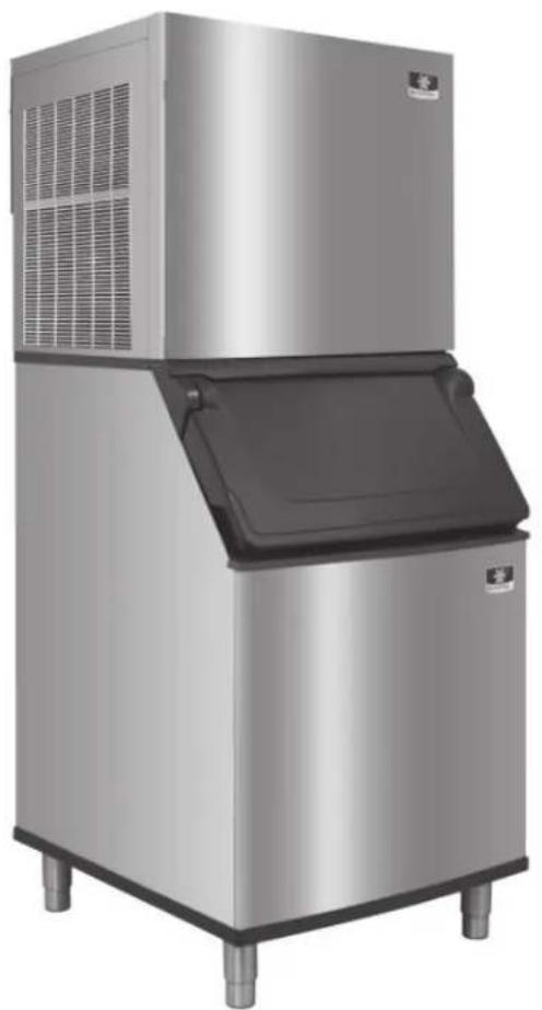
natural_image
Exterior view of a modern stainless steel ice cream maker with cooling unit (no visible text or symbols)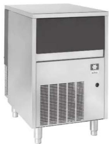
natural_image
Exterior view of a stainless steel industrial ice cream unit with ventilation grilles and a medical cross symbol (no text or labels visible)Original Document
Caution
Read this instruction before operating this equipment
Safety Notices
Safety Notices
Read these precautions to prevent personal injury:
- Read this manual thoroughly before operating, installing or performing maintenance on the equipment. Failure to follow instructions in this manual can cause property damage, injury or death.
- Routine adjustments and maintenance procedures outlined in this manual are not covered by the warranty.
- Proper installation, care and maintenance are essential for maximum performance and trouble-free operation of your equipment. Visit our website www.manitowocice.com for manual updates, translations, or contact information for service agents in your area.
- This equipment contains high voltage electricity and refrigerant charge. Installation and repairs are to be performed by properly trained technicians aware of the dangers of dealing with high voltage electricity and refrigerant under pressure. The technician must also be certified in proper refrigerant handling and servicing procedures. All lockout and tag out procedures must be followed when working on this equipment.
- This equipment is intended for indoor use only. Do not install or operate this equipment in outdoor areas.
Definitions
! DANGER
Indicates a hazardous situation that, if not avoided, will result in death or serious injury. This applies to the most extreme situations.
Warning
Indicates a hazardous situation that, if not avoided, could result in death or serious injury.
! Caution
Indicates a hazardous situation that, if not avoided, could result in minor or moderate injury.
Notice
Indicates information considered important, but not hazard-related (e.g. messages relating to property damage).
NOTE: Indicates useful, extra information about the procedure you are performing.
▲Warning
Follow these precautions to prevent personal injury during installation of this equipment:
- Installation must comply with all applicable equipment fire and health codes with the authority having jurisdiction.
- To avoid instability the installation area must be capable of supporting the combined weight of the equipment and product. Additionally the equipment must be level side to side and front to back.
- Ice machines require a deflector when installed on an ice storage bin. Prior to using a non-OEM ice storage system with this ice machine, contact the bin manufacturer to assure their ice deflector is compatible.
- Prior to installing a non-OEM ice storage system with this ice machine, follow the manufacturers installation procedures and verify the location and installation meets the local/national mechanical codes and stability requirements.
-
Remove all removable panels before lifting and installing and use appropriate safety equipment during installation and servicing. Two or more people are required to lift or move this appliance to prevent tipping and/or injury.
-
Legs or casters must be installed and the legs/casters must be screwed in completely. When casters are installed the mass of this unit will allow it to move uncontrolled on an inclined surface. These units must be tethered/secured to comply with all applicable codes. Swivel casters must be mounted on the front and rigid casters must be mounted on the rear. Lock the front casters after installation is complete.
- Connect to a potable water supply only.
- Do not damage the refrigeration circuit when installing, maintaining or servicing the unit.
- This equipment contains refrigerant charge. Installation of the line sets must be performed by a properly trained and EPA certified refrigeration technician aware of the dangers of dealing with refrigerant charged equipment.

DANGER
Follow these flammable refrigeration system requirements during installation, use or repair of this equipment.
- Refer to nameplate - Ice machine models may contain up to 150 grams of R290 (propane) refrigerant. R290 (propane) is flammable in concentrations of air between approximately 2.1% and 9.5% by volume (LEL lower explosion limit and UEL upper explosion limit). An ignition source at a temperature higher than 470°C is needed for a combustion to occur. Refer to nameplate to identify the type of refrigerant in your equipment.
- To minimize the risk of ignition due to improper installation, replacement parts or service procedures, only refrigeration technicians with flammable refrigerant training who are aware of the dangers of dealing with high voltage electricity and refrigerant under pressure are allowed to work on this equipment.
- All replacement parts must be like components obtained from the equipment manufacturers authorized replacement part network.
- This equipment must be installed in accordance with the ASHRAE 15 Safety Standard for Refrigeration Systems.
- This equipment can not be installed in corridors or hallways of public buildings
-
Installation must comply with all applicable equipment fire and health codes with the authority having jurisdiction.
-
All lockout and tag out procedures must be followed when working on this equipment.
- This equipment contains high voltage electricity and refrigerant charge. Shorting electrical wires to refrigeration tubing may result in an explosion. All electrical power must be disconnected from the system before servicing the system. Refrigerant leaks, can result in serious injury or death from explosion, fire, or contact with refrigerant or lubricant mists.
- Do not damage the refrigeration circuit when installing, maintaining or servicing the unit. Never use sharp objects or tools to remove ice or frost. Do not use mechanical devices or other means to accelerate the defrosting process.
▲ Warning
Follow these electrical requirements during installation of this equipment.
- All field wiring must conform to all applicable codes of the authority having jurisdiction. It is the responsibility of the end user to provide the disconnect means to satisfy local codes. Refer to rating plate for proper voltage.
• This appliance must be grounded. - This equipment must be positioned so that the plug is accessible unless other means for disconnection from the power supply (e.g., circuit breaker or disconnect switch) is provided.
- Check all wiring connections, including factory terminals, before operation. Connections can become loose during shipment and installation.
DANGER
Do not operate equipment that has been misused, abused, neglected, damaged, or altered/modified from that of original manufactured specifications. This appliance is not intended for use by persons (including children) with reduced physical, sensory or mental capabilities, or lack of experience and knowledge, unless they have been given supervision concerning use of the appliance by a person responsible for their safety. Do not allow children to play with, clean or maintain this appliance without proper supervision.
▲ Warning
Follow these precautions to prevent personal injury while operating or maintaining this equipment:
- Read this manual thoroughly before operating, installing or performing maintenance on the equipment. Failure to follow instructions in this manual can cause property damage, injury or death.
- Crush/Pinch Hazard. Keep hands clear of moving components. Components can move without warning unless power is disconnected and all potential energy is removed.
- Moisture collecting on the floor will create a slippery surface. Clean up any water on the floor immediately to prevent a slip hazard.
- Objects placed or dropped in the bin can affect human health and safety. Locate and remove any objects immediately.
- Never use sharp objects or tools to remove ice or frost. Do not use mechanical devices or other means to accelerate the defrosting process.
- When using cleaning fluids or chemicals, rubber gloves and eye protection (and/or face shield) must be worn.
▲Warning
These products are hermetically sealed and may contain fluorinated greenhouse gas R404A. Refer to model/serial label.
! DANGER
Follow these precautions to prevent personal injury during use and maintenance of this equipment:
- It is the responsibility of the equipment owner to perform a Personal Protective Equipment Hazard Assessment to ensure adequate protection during maintenance procedures.
- Do Not Store Or Use Gasoline Or Other Flammable Vapors Or Liquids In The Vicinity Of This Or Any Other Appliance. Never use flammable oil soaked cloths or combustible cleaning solutions for cleaning.
- All covers and access panels must be in place and properly secured when operating this equipment.
- Risk of fire/shock. All minimum clearances must be maintained. Do not obstruct vents or openings.
- Failure to disconnect power at the main power supply disconnect could result in serious injury or death. The power switch DOES NOT disconnect all incoming power.
- All utility connections and fixtures must be maintained in accordance with the authority having jurisdiction.
-
Turn off and lockout all utilities (gas, electric, water) according to approved practices during maintenance or servicing.
-
Units with two power cords must be plugged into individual branch circuits. During movement, cleaning or repair it is necessary to unplug both power cords.
- Never use a high-pressure water jet for cleaning on the interior or exterior of this unit. Do not use power cleaning equipment, steel wool, scrapers or wire brushes on stainless steel or painted surfaces.
- Two or more people are required to move this equipment to prevent tipping.
- Locking the front casters after moving is the owner's and operator's responsibility. When casters are installed, the mass of this unit will allow it to move uncontrolled on an inclined surface. These units must be tethered/secured to comply with all applicable codes.
- The on-site supervisor is responsible for ensuring that operators are made aware of the inherent dangers of operating this equipment.
- Do not operate any appliance with a damaged cord or plug. All repairs must be performed by a qualified service company.
THIS PAGE INTENTIONALLY LEFT BLANK
Table of Contents
Safety Notices
Safety Notices .... 3
Section 1 General Information
Model Numbers 11
Flake UnderCounter Models ....11
Flake Modular Models 11
Nugget UnderCounter Models ....11
Nugget Modular Models ....11
Adapters 12
RFF2500 Bin Adapter Installation ....12
Warranty Information.... 12
Arctic Pure Water Filter System 12
Manitowoc Cleaner and Sanitizer 12
Legs....12
Section 2 Installation Instructions
Location of Ice Machine....13
Clearance Requirements ....13
Installation Requirements 13
Ice Machine Heat of Rejection 13
Water and Drain Requirements 14
Potable Water Requirements ....14
Drain Connections....14
Cooling Tower Applications 14
Ice Machine Water Usage ....14
Water Supply and Drain Line Sizing/Connections 15
Electrical Service 16
Voltage 16
Fuse/Circuit Breaker....16
Ground Fault Circuit Interrupter ....16
Minimum Power Cord Specifications ....16
For United Kingdom Only 16
Maximum Breaker Size & Minimum Circuit Amperage Chart 17
QuietQube ^® Remote Condensing Unit 17
Refrigeration System Installation
Remote Condensing Unit Only 18
Usage with Non-Manitowoc Condensing Units 18
Refrigeration Line Set Installation
Remote Condensing Unit Only 19
General....19
A. Line Set Length....19
B. Line Set Rise or Drop....19
C. Suction Line Oil Traps....20
Installation Check List....22
Additional Checks for QuietQube® Models 22
Section 3 Operation
Bin Thermostat and Evaporator Low Temperature Safety Adjustment Chart 23
UFF0200/UNF0200/UNP0200/UFF0350/UFP0350/UNF0300/UNP0300 Operation ..... 23
RFF0320/RNF0320/RFP0320/RNP0320 Operation.... 23
RNF0620/RFF0620/RNP0620/RFP0620/RNF1020C/RNF1100/RNP1100/RFF1200C/RFF1300/
RNF2000C/RFF2200C/RFF2500 Operation 24
Section 4 Maintenance
Interior Cleaning and Sanitizing 25
Descaling/Sanitizing Procedure 25
Heavily Scaled Cleaning Procedure 25
Exterior Cleaning 25
Descaling/Sanitizing Procedure 25
Procedure to Clean Heavily Scaled Flake Ice Machines 26
Removal of Parts for Cleaning/Sanitizing 27
Ice Chute Removal....27
Air-Cooled Condenser Cleaning 28
Removal from Service/Winterization 28
Water-Cooled Ice Machines 28
Section 5 Troubleshooting
Checklist.... 29
Section1
GeneralInformation
Model Numbers
This manual covers the following models:
FLAKE UNDERCOUNTER MODELS
| Self-Storage Air-Cooled | |
| R404A Refrigerant R290 Refrigerant | |
| UFF0200A UFP0200A | |
| UFF0350A UFP0350A | |
NUGGET UNDERCOUNTER MODELS
| Self-Storage Air-Cooled | |
| R404A Refrigerant R290 Refrigerant | |
| UNF0200A UNP0200A | |
| UNF0300A UNP0300A | |
FLAKE MODULAR MODELS
| Modular Air-Cooled | Modular Water-Cooled | QuietQube® Head Section | RCUF Remote Condensing Unit |
| RFF0320A RFP0320A | --- --- --- | ||
| RFF0620A RFP0620A | RFF0620W RFP0620W | --- --- | |
| --- --- RFF1220C RCUF1200 | |||
| RFF1300A RFF1300W --- --- | |||
| --- --- RFF2200C RCUF2200 | |||
| RFF2500A --- --- | |||
NUGGET MODULAR MODELS
| Modular Air-Cooled | Modular Water-Cooled | QuietQube® Head Section | RCUF Remote Condensing Unit |
| RNF0320A RNP0320A | --- --- --- | ||
| RNF0620A RNP0620A | RNF0620W RNP0620W | --- --- | |
| RNF1100A RNP1100A | RNF1100W RNF1100W RNF1100W RNF1100W RNF1100W RNF1100W RNF1100W RNF1100W RNF1100W RNF1100W RNF1100W RNF1100W RNF1100W RNF1100W RNF1100W RNF | --- --- | |
| --- --- RNF | 2000C RCUF2200 |
Warning
Remove all ice machine panels before lifting and installing.
Caution
Flake ice machines must be installed on a bin. Flake ice machines cannot be installed on dispensers.
Adapters
RFF2500 BIN ADAPTER INSTALLATION
⚠ Warning
PERSONAL INJURY POTENTIAL
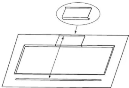
RFF2500 ice machines are not approved for use on B or D series bins. RFF2500 ice machines ship with a bracket that must be used when installing on F Series bins.
- Refer to diagram. Place bracket on bin top and slide back to engage
- Place ice machine on bin: ice machine must fit between bracket and front ridge.
Warranty Information
Visit www.manitowocice.com for:
• Warranty Verification
• Warranty Registration
• View and download a copy of your warranty
Arctic Pure Water Filter System
Engineered specifically for Manitowoc ice machines. This water filter is an efficient, dependable, and affordable method of inhibiting scale formation, filtering sediment, and removing chlorine taste and odor.
Manitowoc De-scaler and Sanitizer
Manitowoc Ice Machine Metal Safe De-scaler is available in convenient 16 oz. (473 ml) bottles. Manitowoc Ice Machine Sanitizer is available in 16 oz. (473 ml) and 1 gal (3.78 L) bottles.
| De-scaler Part Number Sanitizer Part Number | |
| 16 oz. 000000084 16 oz. 9405653 | |
| 1 Gallon 9405813 | |
LEGS
Six inch legs and casters are available for undercounter ice machines. Six inch legs are also available for bins. Refer to www.manitowocice.com for option details.
Section 2 Installation Instructions
Location of Ice Machine
The location selected for the ice machine must meet the following criteria. If any of these criteria are not met, select another location.
- The location must be free of airborne and other contaminants.
- This equipment is intended for indoor use only. Do not install or operate this equipment in outdoor areas.
- The air temperature must be at least 50^ (10°C), but must not exceed 110^ (43°C).
- The water temperature must be at least 37^ (3°C), but must not exceed 90^ (32°C).
- The location must not be near heat-generating equipment or in direct sunlight.
- The location must be capable of supporting the weight of the ice machine and a full bin of ice.
- The location must allow enough clearance for water, drain and electrical connections in the rear of the ice machine.
- The location must not obstruct airflow through or around the ice machine.
CLEARANCE REQUIREMENTS
| Undercounter Units Air | Cooled Water-Cooled | |
| Top 0" (0 cm) 0" | (0 cm) | |
| Sides 2" (5 cm) 2" | (5 cm) | |
| Back 8" (20 cm) 8" | (20 cm) | |
NOTE: Allowance must be made for removal when the ice machine is built in. Removal of the top panel is required for de-scaling & sanitizing.
| Modular Units | Air-Cooled | Water-Cooled | QuietQube® Air-Cooled |
| Top/Sides 8" (20 cm) | 8" (20 cm) | 0" (0 cm) | |
| Back | 5" (13 cm) | 5" (13 cm) | 0" (0 cm) |
| RCUF Units | Remote Condensing Unit |
| Front/Back | 24" (61 cm) |
| Sides/Top | 6" (15.2 cm) |
| 24 inches clearance on top and sides is recommended for serviceability. | |
Installation Requirements
- The ice machine and bin must be level.
• Install the bin drain and ice machine drain separately. - Ice machine drain must be vented.
- Bin drain termination must have an air gap.
- When local code requires, a backflow preventer must be installed on the water inlet line.
- The ice machine and bin must be sanitized after installation.
- Local water conditions may require treatment of the water to inhibit scale formation, filter sediment, and remove chlorine odor and taste.
- Routine adjustments and maintenance procedures outlined in this manual are not covered by the warranty.
Ice Machine Heat of Rejection
| SeriesIce Machine | Heat of Rejection Btu/h |
| UFF0200 - RFF0320 - RFP0320 2400 | |
| UNF0200 - UNP0200 | 2800 |
| UNF0300 - UFF0350 | 5000 |
| RNF0320 - RNP0320 | 3075 |
| RFF0620 - RNF0620 - RNP0620 | 5200 |
| RNF1100 - RNP1100 | 7500 |
| RFF1300 | 7500 |
| RFF2500 | 17000 |
Ice machines, like other refrigeration equipment, reject heat through the condenser. It is helpful to know the amount of heat rejected by the ice machine when sizing air conditioning equipment.
This information is also necessary when evaluating the benefits of using water-cooled or remote condensers to reduce air conditioning loads. The amount of heat added to an air conditioned environment by an ice machine using a water-cooled or remote condensing unit is negligible.
Knowing the amount of heat rejected is also important when sizing a cooling tower for a water-cooled condenser.
Water and Drain Requirements
POTABLE WATER REQUIREMENTS
Follow these guidelines to install water inlet lines:
- Do not connect the ice machine to a hot water supply. Be sure all hot water restrictors installed for other equipment are working. (Check valves on sink faucets, dishwashers, etc.)
- If water pressure exceeds the maximum of 80 psig (552 kPA) recommended pressure, obtain a water pressure regulator from your local plumbing supply house.
- Install a water shut-off valve and union for both the ice making and condenser water lines.
• Insulate water inlet lines to prevent condensation. - Plumbing must conform to local codes.
Caution
Do not apply heat to water valve inlet fitting or over-tighten. This will damage plastic water inlet connection.
DRAIN CONNECTIONS
Follow these guidelines when installing drain lines to prevent drain water from flowing back into the ice machine and storage bin:
- Drain lines must have a 1.5 inch drop per 5 feet of run (2.5 cm per meter), and must not create traps.
- The floor drain must be large enough to accommodate drainage from all drains.
- Run separate bin and water-cooled condenser drain lines. Insulate them to prevent condensation.
- Vent the ice machine drain to the atmosphere. The ice machine drain requires an 18" (46 cm) vent. Do not vent the condenser drain on water-cooled models.
- Drains must have a union or other suitable means to allow in-place disconnection from the ice machine when servicing is required.
COOLING TOWER APPLICATIONS
A water cooling tower installation does not require modification of the ice machine. The water regulator valve for the condenser continues to control the refrigeration discharge pressure.
It is necessary to know the amount of heat rejection, and pressure drop through the condenser and water valves (inlet and outlet) when using a cooling tower on an ice machine.
- Water entering the condenser must not be lower than 37^ F ( 3^ C) or exceed 90^ F ( 32^ C).
- Water flow through the condenser must not exceed 5 gal. (19 L) per minute.
- Allow for a pressure drop of 7 psi (48 kPa) between the condenser water inlet and the outlet of the ice machine.
- Water exiting the condenser must not exceed 110°F (43°C).
ICE MACHINE WATER USAGE
| Series Ice Machine | Potable Water Gal/100Lbs Ice | Condenser Gal/100Lbs Ice |
| UFF0200 - UFP0200 - UNP0200 | 12.0 — | |
| RFF0320 - RNF0320 - RFP0320 | 12.0 — | |
| RNF0620 - RNP620 12.0 | 109 | |
| RFF0620 - RFP0620 12.0 | 106 | |
| RNF1100 - RNP1100 12.0 | 131 | |
| RFF1300 12.0 116 | ||
| RFF2500 12.0 138 |
WATER SUPPLY AND DRAIN LINE SIZING/CONNECTIONS
| Location | Water TempMin/Max | Water PressureMin/Max | Fitting/Min Tubing Size |
| PotableWater Inlet | 37°/90°F(3°/32°C) | 20/80 psi(138/552 kPA) | 3/8" FPT |
| PotableWater Drain | --- --- 1/2" MPT | ||
| CondenserWater Inlet | 37°/90°F(3°/32°C) | 20/150 psi(138/1034 kPA) | 3/8" FPTRFF2500 only = 1/2" FPT |
| CondenserWater Drain | --- --- 1/2" MPT | ||
| Bin Drain --- --- 3/4" FPT | |||
| Large Capacity Bin Drain --- --- 1" FPT | |||
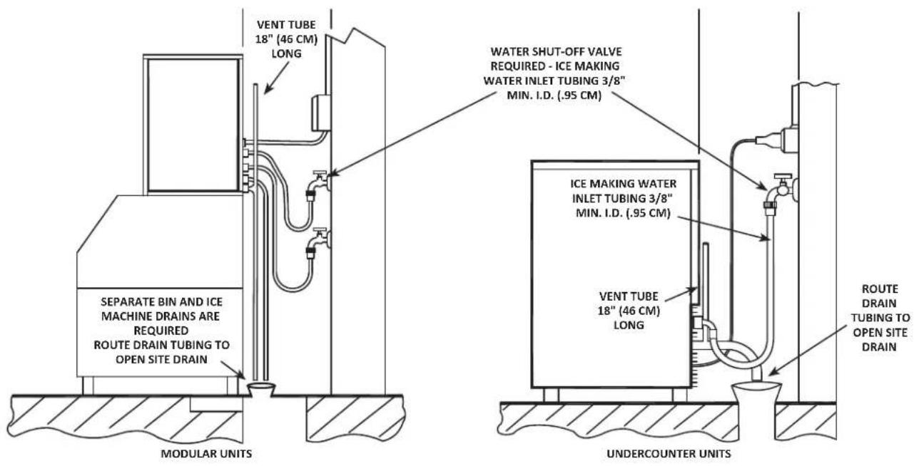
Typical Water Supply Drain Installation
Electrical Service
▲Warning
All wiring must conform to local, state and national codes.
VOLTAGE
The maximum allowable voltage variation is ±10% of the rated voltage at ice machine start-up (when the electrical load is highest).
▲Warning
The ice machine must be grounded in accordance with national and local electrical codes.
All electrical work, including wire routing and grounding, must conform to local, state and national electrical codes. The following precautions must be observed:
- The ice machine must be grounded.
- A separate fuse/circuit breaker must be provided for each ice machine.
- A qualified electrician must determine proper wire size dependent upon location, materials used and length of run (minimum circuit ampacity can be used to help select the wire size).
- Check all ground screws in the control box and verify they are tight before starting the ice machine.
Important
Observe correct polarity of incoming line voltage. Incorrect polarity can lead to erratic ice machine operation. L1 is the wire colored brown and L2/N is the wire colored blue.
FUSE/CIRCUIT BREAKER
A dedicated circuit and a separate fuse/circuit breaker are required for each ice machine.
GROUND FAULT CIRCUIT INTERRUPTER
We do not recommend the use of a GFCI/GFI circuit protection with our equipment. If a GFCI/GFI is required by code, use a GFCI/GFI breaker rather than outlet which is more prone to intermittent nuisance trips than panel circuit breakers.
MINIMUM POWER CORD SPECIFICATIONS
The wire size to the receptacle is dependent upon location, materials used, length of run, etc., so it must be determined by a qualified electrician. Local, state or national requirements will supersede our minimum requirements.
FOR UNITED KINGDOM ONLY
As the colors of the wires in the mains lead of the appliance may not correspond with the colored markings identifying the terminals in your plug, proceed as follows:
- The wire which is colored green and yellow must be connected to the terminal in the plug which is marked with the letter E or by the earth ground symbol by colored green or green and yellow.
- The wire colored blue must be connected to the terminal which is marked with the letter N or colored black.
- The wire colored brown must be connected to the terminal which is marked with the letter L or colored red.
Maximum Breaker Size & Minimum Circuit Amperage Chart
Important
Due to continuous improvements, this information is for reference only. Please refer to the ice machine serial number tag to verify electrical data. Serial tag information overrides information listed on this page.
| Series Ice Machine | Voltage/Phase/Cycle | Air-Cooled Water-Cooled | QuietQube® | |||||
| MaxFuse/CircuitBreaker | MinCircuitAmps | TotalCircuitAmps | MaxFuse/CircuitBreaker | MinCircuitAmps | MaxFuse/CircuitBreaker | TotalCircuitAmps | ||
| UNF0200 115/1/60 | 15 Amp — 7.5 — | — — — | ||||||
| UNP0200 115/1/60 | 15 Amp — *7.5 | — — — | ||||||
| UFF0200 115/1/60 | 15 Amp — 7.5 — | — — — | ||||||
| UFP0200 115/1/60 | 15 Amp — *7.5 | — — — | ||||||
| UFF0350 115/1/60 | 15 Amp — 10.0 | — — — | ||||||
| UFP0350 115/1/60 | 15 Amp — *10.0 | — — — | ||||||
| UNF0300 115/1/60 | 15 Amp — 10.0 | — — — | ||||||
| UNP0300 115/1/60 | 15 Amp — *10.0 | — — — | ||||||
| RFF0320 | 115/1/60 20 Amp | 12.8 — — — — — | ||||||
| RFP0320 115/1/60 | 20 Amp * | 12.8 — — — — — | ||||||
| RNF0320 115/1/60 | 20 Amp | 12.8 — — — — — | ||||||
| RNP0320 115/1/60 | 20 Amp * | 12.8 — — — — — | ||||||
| RNF0620 115/1/60 | 25 Amp | 16.3 — 25 Amp | 15.4 — — | |||||
| RNP0620 115/1/60 | 25 Amp * | 16.3 — 25 Amp | *15.4 — — | |||||
| RFF0620 | 115/1/60 25 Amp | 16.3 — 25 Amp | 15.4 — — | |||||
| 208-230/1/60 | 15 Amp | 8.7 | — | 15 Amp | 8.2 | — | — | |
| RFP0620 115/1/60 | 25 Amp * | 16.3 — 25 Amp | *15.4 — — | |||||
| RNF1100 RNF1020C | 115/1/60 | — — — — — 15 Amp | 2.9 | |||||
| 208-230/1/60 | 20 Amp | 14.2 | — | 20 Amp | 13.7 | — | — | |
| RNP1100 | 208-230/1/60 | 20 Amp | *14.2 | — | — | — | — | — |
| RFF1300 | 208-230/1/60 | 20 Amp | 12.5 | — | 20 Amp | 12.5 | 15 Amp | 1.4 |
| RNF2000C RFF2200C 208- | 230/1/60 | — — — — — 15 Amp | 3.2 | |||||
| RFF2500 | 208-230/3/60 | 20 Amp | 15.0 | — | — | — | — | — |
| * Indicates preliminary data | ||||||||
NOTE: Maximum allowable voltage variation at compressor start-up is ±10% of voltage listed above and on the model/serial plate.
QUIETQUBE ^® REMOTE CONDENSING UNIT
| Condensing Unit | Voltage/Phase/Cycle | Maximum Fuse/Circuit Breaker | Minimum Circuit Amps |
| RCUF1200 | 208-230/1/60 | 15 Amp | 15 |
| 208-230/3/60 | 15 Amp | 15 | |
| RCUF1000 | 208-230/1/60 | 15 Amp | 15 |
| 208-230/3/60 | 15 Amp | 15 | |
| RCUF2200 | 208-230/3/60 | 15 Amp | 15 |
Refrigeration System Installation Remote Condensing Unit Only
| QuietQube®Ice Machine | Remote Condensing Unit | Line Set* |
| RNF1020C | RCUF1000 | RC-51 |
| RFF1220C | RCUF1200 | |
| RNF2000C | RCUF2200 | |
| RFF2200C | RCUF2200 |
| *Line Set Suction Line Liquid Line | ||
| RC 51 | 5/8 inch(15.9 mm) | 3/8 inch(9.5 mm) |
Important
Manitowoc remote systems are only approved and warranted as a complete new package. Warranty on the refrigeration system will be void if a new ice machine head section is connected to pre-existing (used) tubing or condensing units or vice versa.
USAGE WITH NON-MANITOWOC CONDENSING UNITS
Manitowoc Remote Condensing Units are specifically designed for usage with a QuietQube® Ice Machine Head Section. Standard condensing units and Non-Manitowoc condensing units are not approved for use with a QuietQube® Ice Machine Head Section.
! Caution
The 60-month compressor warranty (including the 36-month labor replacement warranty) will not apply if the Manitowoc Ice Machine and Manitowoc Remote Condensing Unit are not installed according to specifications. This warranty also will not apply if the refrigeration system is modified with a condenser, heat reclaim device, or other parts or assemblies not manufactured by Manitowoc Ice.
Factory Equipment Refrigeration Amounts
ICE MACHINE HEAD SECTION
Each ice machine condensing unit ships from the factory with a refrigerant charge appropriate for the entire system operation. The serial tag on the ice machine indicates the refrigerant charge. The refrigerant charge is sufficient to operate the ice machine in ambient temperatures between -20°F (-28.9°C) and 120°F (48.9°C). With line set lengths of up to 100 feet (30.5 m).
⚠ Warning
Potential Personal Injury Situation
The QuietQube® Condensing Unit contains the refrigerant charge. Installation and brazing of the line sets must be performed by a properly trained and EPA-certified refrigeration technician aware of the dangers of dealing with refrigerant-charged equipment.
Refrigeration Rated Tubing and Trap Kits are shipped capped with atmospheric pressure.
Warning
Installation of a QuietQube® Condensing Unit may require the use of special equipment for placement. Trained and qualified personnel are required for proper rigging and lifting.
Refrigeration Line Set Installation Remote Condensing Unit Only
GENERAL
Refrigeration line set installations consist of vertical and horizontal line set distances between the ice machine and the condensing unit. The following guidelines, drawings and calculation methods must be followed to assure proper oil return and remote condensing unit/ice machine operation.
The refrigeration line set installer must be USA Government-Environmental Protection Agency (EPA) certified in proper refrigerant handling and servicing procedures.
▲Warning
The QuietQube ^® Condensing unit contains refrigerant charge. The two refrigeration valves must remain closed until proper installation of the line sets is completed.
▲Warning
Disconnect electrical power to the ice machine head section and remote condensing unit before proceeding.
Step 1 Verify Ice Machine and Remote Condensing Unit Locations Are Within Guidelines
Prior to installation of the ice machine head section and remote condensing unit be sure that the distance between them is within the line set routing guidelines outlined in this manual.
Roof/Wall Penetration
If required, cut a 3-inch (76.2 mm) circular hole in the wall or roof for routing of refrigeration tubing. A qualified person must perform all roof penetrations.
Step 2 Route Refrigeration Tubing
Properly route refrigeration tubing between the ice machine head section and the remote condensing unit.
A. LINE SET LENGTH
100 feet (30.5 m) Length: The maximum measured length the line set can be.
The receiver is designed to hold a charge sufficient to operate the ice machine in ambient temperatures between -20^ F ( -28.9^ C) and 120^ F ( 48.9^ C), with line set lengths of up to 100 feet (30.5 m). The maximum amount of line set which can be exposed on the rooftop is 25% of the total length of the line set.
Important
QuietQube ^® ice machines will not function with line sets greater than 100 feet (30.5 m). Do not attempt to go beyond this distance and add refrigerant charge to compensate!
B. LINE SET RISE OR DROP
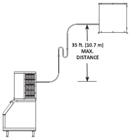
35 feet (10.7 m) Rise: The maximum distance the remote condensing unit can be above the ice machine.
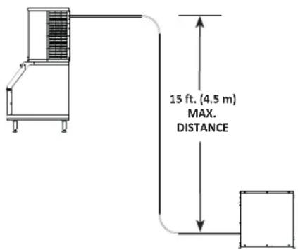
15 feet (4.5 m) Drop: The maximum distance the remote condensing unit can be below the ice machine.
C. SUCTION LINE OIL TRAPS
Caution
Do not form unwanted traps in refrigeration lines. Never coil excess refrigeration tubing.
0 to 20 feet (0 to 6.1 m) Rise: No oil trap is required when the condensing unit is located 20 feet (6.1 m) or less above the ice machine head section.
21 to 35 feet (6.4 to 10.7 m) Rise: The suction line requires an additional Oil Trap ("S" type) to be installed. Install the trap as close as possible to midpoint between the ice machine head section and remote condensing unit. S-Trap Kits are available from Manitowoc.
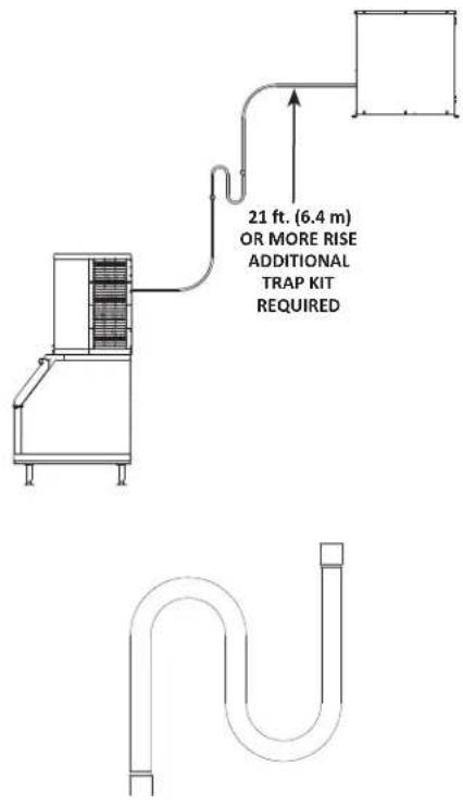
Step 3 Lengthening or Reducing Line Set Lengths
Caution
Do not form unwanted traps in refrigeration lines. Never coil excess refrigeration tubing.
When the line set requires shortening or lengthening, do so before connecting the line set to the ice machine head section or the remote condensing unit.
Step 4 Connecting the line set
To prevent oxidation of the copper, purge line set with dry nitrogen while brazing.
A. Connect the Line Set to the Remote Condensing Unit
The condensing unit is shipped with a refrigerant charge. The line set shut-off valves must remain closed during brazing. Protect the valves from heat during the brazing process. Wrap the valves in a wet rag or other type of heat sink prior to brazing. Cool braze joint with water immediately after brazing to prevent heat migration to the valve.
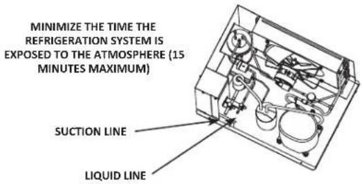
B. Connect the Line Set to the Ice Machine Head Section
- Cut the suction and liquid tubing with a tubing cutter, leaving enough tubing to easily braze.
- Connect the line set.
- Cool braze joint with water immediately after brazing to prevent heat migration.
Step 5 Pressure Test and Evacuate Line Set and Ice Machine Head Section
- Pressure testing and evacuation can be performed from the ice machine head section or CVD condensing unit shut-off valves.
- Schrader valve core removal tools that allow for removal and installation of the valve cores without removing manifold gauge set hoses are recommended to decrease the evacuation time.
- Pressure test @ 150 psi (1000 kPa) for a minimum of 15 minutes.
• Minimum evacuation level is 500 microns.
Step 6 Open the valves and leak check the refrigeration system prior to startup of the ice machine
A. Backseat (open-turn counterclockwise) the suction shutoff valve.
B. Backseat (open-turn counterclockwise) the liquid line shutoff valve.
Disconnect power to the remote condensing unit. Confirm water is supplied to the ice machine, then place the ice machine rocker switch in the ON position. The water trough will fill and initiate an 8 minute delay period. When the 8 minute delay period ends the liquid line solenoid valve will energize and equalize the low side and high side pressures. Leak check the line set connections, S trap and all factory joints throughout the entire system. When the leak check is complete, place the rocker switch in the OFF position. Connect power to the remote condensing unit and allow system to pump down.
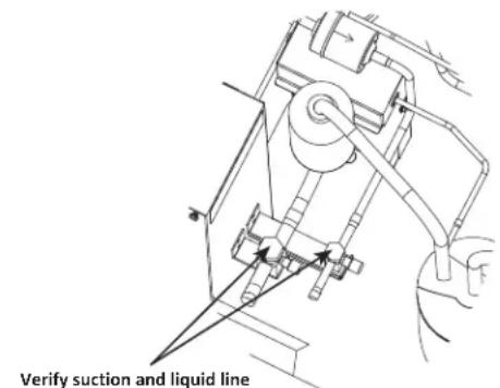
Verify suction and liquid line shut-off valves are open before operating the ice machine
Important
All refrigeration valve caps must be reinstalled to prevent future refrigeration leaks.
Verify O-ring in Schrader valve caps are intact and reinstall on shutoff valves to prevent refrigerant leakage. Replace shutoff valve access caps and torque to the following specifications.
Torque Values
| Stem 18-20 ft. lbs. (24.4-27.1 Nm) |
| Caps 12-15 ft. lbs. (16.3-20.3 Nm) |
| Schrader Core 1.5-3 in. lbs. (0.17-0.34 Nm) |
Step 7 Insulation Requirements
To prevent condensation, the entire suction line must be insulated. All insulation must be airtight and sealed at both ends.
The following insulation requirements prevent condensation at 90^ F ( 32^ C) ambient 90% Relative Humidity. If higher humidity is expected, increase insulation thickness.
The entire suction line set requires:
| Suction Line Liquid Line | Min. Insulation Thickness | |
| 5/8 in. (16 mm) 3/8 | in. (10 mm) | 3/8 in. (9 mm)Suction Line3/8 in. (9 mm)Liquid Line |
Important
To prevent condensation, the entire suction line must be insulated. All insulation must be airtight and sealed at both ends.
The minimum requirements are for conditions at or below 90% humidity and 90°F (32°C) ambient. When higher humidity will be experienced, or local code requires, insulation wall thickness will need to be increased.
Installation Check List
All Manitowoc ice machines are factory-operated and adjusted before shipment. Adjustments and maintenance procedures outlined in this manual are the responsibility of the owner/operator and are not covered by the warranty.
Is the ice machine level?
☐ Is the ice machine and adapter (when used) secured to the dispenser?
☐ Have all of the electrical and water connections been made?
☐ Has the supply voltage been tested and checked against the rating on the nameplate?
☐ Is there proper clearance around the ice machine for air circulation?
□ Is the ice machine grounded and polarity correct?
☐ Has the ice machine been installed where ambient temperatures will remain in the range of 50^ - 110^ F ( 10^ - 43^ C)?
☐ Is the ice machine installed where the incoming water temperature is within the range of 37^ - 90^ ( 3^ - 32^ )?
☐ Is there a separate drain for the water-cooled condenser?
□ Is there a separate drain for the dispenser?
□ Is the ice making water turned on?
☐ Are all electrical leads free from contact with refrigeration lines and moving equipment?
☐ Has the owner/operator been instructed regarding maintenance and the use of Manitowoc De-scaler and Sanitizer?
☐ Has the owner/operator completed the warranty registration card?
☐ Has the ice machine and bin been sanitized?
☐ Is the rocker switch set to ON?
Additional Checks for QuietQube® Models
☐ Is the line set length, rise and drop within the guidelines?
☐ Are the suction and liquid line shut-off valves open?
□ Is the line set routed properly?
☐ Are both refrigeration lines to remote condensing unit run so they do not lay in water and are properly insulated?
☐ Does the condenser fan motor(s) operate properly after start-up?
☐ Have all the refrigeration fittings and joints been leak checked?
☐ Has the condenser/condensing unit been installed to prevent any roofing damage?
☐ Have the refrigeration lines been insulated and secured properly to prevent vibration?
☐ Has the RCUF remote condensing unit been located where ambient temperatures will remain in the range of -20^ to 120^ F ( -29^ to 48.9^ C)?
☐ Is a refrigeration oil trap (S-trap) installed if the condenser is installed 21 to 35 feet (6 to 11 m) above the ice machine head?
Section3
Operation
NOTE: Flake and nugget ice machines use an auger to remove ice from the evaporator. Occasional noises (creaks, groans, squeaks, or pops) are a normal part of the ice making process.
Bin Thermostat and Evaporator Low Temperature Safety Adjustment Chart
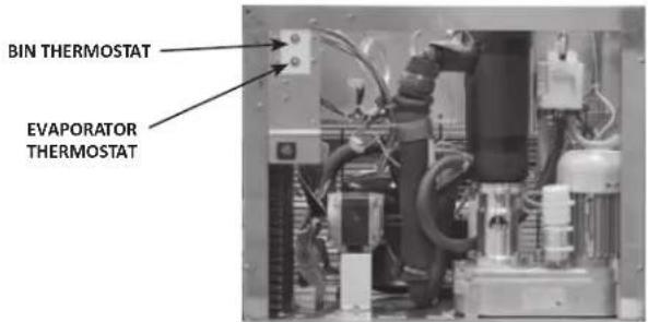
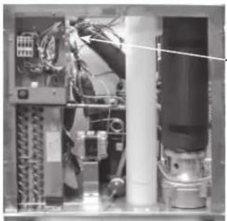
The bin thermostat sensing bulb is located in the ice chute or bin and turns the ice machine on and off as the level of ice in the ice chute or bin changes. The evaporator low temperature safety protests the evaporator and compressor from damage caused by water loss or gear motor failure.
| Model | Bin Thermostat Setting | Evaporator Thermostat Setting |
| UNF0200 5 5 | ||
| UNP0200 *5 *5 | ||
| UFF0200 5 5 | ||
| UFP0200 *5 *5 | ||
| UNF0300 5 6 | ||
| UNP0300 *5 *6 | ||
| RFF0320 3 7 | ||
| RNF0320 3 6 | ||
| RNP0320 *3 *6 | ||
| UFF0350 5 7 | ||
| UFP0350 *5 *7 | ||
| RNF0620 2 --- | ||
| RNP0620 *2 --- | ||
| RFF0620 3 --- | ||
| RFP0620 *3 --- | ||
| RNF1020C 3 --- | ||
| RNF1100 3 --- | ||
| RNP1100 *3 --- | ||
| RFF1220C 3 --- | ||
| RFF1300 3 --- | ||
| RNF2000C | *3 --- | |
| RFF2200C 3 --- | ||
| RFF2500 3 --- | ||
| * Indicates preliminary data | ||
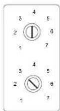
BIN THERMOSTAT
SMALL NUMBERS = LESS ICE IN BIN
LARGE NUMBERS = MORE ICE IN BIN
EVAPORATOR LOW TEMPERATURE
SAFETY THERMOSTAT
INCORRECT SETTINGS WILL CAUSE ICE MACHINE
TO SHUT OFF
UFF0200/UNF0200/UNP0200/UFF0350/UFP0350/UNF0300/UNP0300 Operation
The ice machine will not start until:
A. The rocker switch is moved to "ON".
B. Ice does not contact the bin thermostat bulb.
C. The water reservoir is full of water.
Placing the toggle switch in the ON position starts the gear motor and refrigeration system. The float valve controls the water inlet valve and water level. The freeze cycle ends when ice contacts the bin thermostat. The ice machine will restart when ice no longer contacts the bin thermostat.
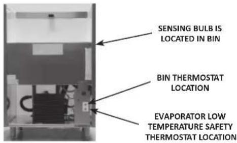
RFF0320/RNF0320/RFP0320/RNP0320 Operation
The ice machine will not start until:
A. The rocker switch is moved to "ON".
B. Ice does not contact the bin thermostat bulb.
C. The water reservoir is full of water.
Placing the toggle switch in the ON position starts the gear motor and a 8 minute compressor time delay. The compressor starts and the float valve controls the water inlet valve and water level. The freeze cycle ends when ice contacts the bin thermostat. The ice machine remains off until ice no longer contacts the bin thermostat.
RNF0620/RFF0620/RNP0620/RFP0620/RNF1020C/RNF1100/RNP1100/RFF1200C/RFF1300/RNF2000C/RFF2200C/RFF2500 Operation
The ice machine will not start until:
A. The rocker switch is moved to "ON".
B. Ice does not contact the bin thermostat bulb.
C. The water reservoir is full of water.
Placing the toggle switch in the ON position starts the gear motor. After the rotation speed sensor verifies 8 minutes of correct rotation, the time delay ends and the compressor starts. The ice machine will continue to make ice until ice contacts the bin thermostat. The ice machine remains off until ice no longer contacts the bin thermostat.
natural_image
Interior view of an electronic equipment cabinet with visible circuitry and wiring (no text or symbols)BIN THERMOSTAT IS LOCATED ON SIDE OF CONTROL BOX
Section4 Maintenance
Interior De-scaling and Sanitizing
Maintenance procedures covered in this manual are not covered by the warranty.
! Caution
Use only Manitowoc approved Metal Safe Ice Machine De-sclae (part number 000000084) and Sanitizer (part number 9405653). Do not mix De-scaler and Sanitizer solutions together. It is a violation of Federal law to use these solutions in a manner inconsistent with their labeling. Read and understand all labels printed on bottles before use.
▲Warning
Wear rubber gloves and safety goggles (and/or face shield) when handling Ice Machine De-scaler or Sanitizer.
DETAILED DE-SCALING/SANITIZING PROCEDURE
This procedure must be performed once every six months.
- All ice must be removed from the bin.
- The ice machine and bin must be disassembled, de-scaled and sanitized.
- The ice machine produces ice with the de-scaler and sanitizer solutions.
- All ice produced during the de-scaler and sanitizing procedure must be discarded.
- Sanitizing Procedures can be performed independently and more frequently than De-scaling as needed (detailed de-scaling must be performed once every six months).
HEAVILY SCALED DE-SCALING PROCEDURE
Perform this procedure if you have some or all of these symptoms.
- Grinding, popping or squealing noises from the evaporator.
- Grinding noise from gearbox.
- Ice machine trips speed sensor.
NOTE: A De-scaling/Sanitizing Procedure must be performed after this procedure.
Exterior Cleaning
Wipe surfaces with a damp cloth rinsed in water to remove dust and dirt from the outside of the ice machine. If a greasy residue persists, use a damp cloth rinsed in a mild dish soap and water solution. Wipe dry with a clean, soft cloth. Never use steel wool or abrasive pads for cleaning. Never use chlorinated, citrus based or abrasive cleaners on exterior panels and plastic trim pieces.
Detailed De-scaling and Sanitizing Procedure
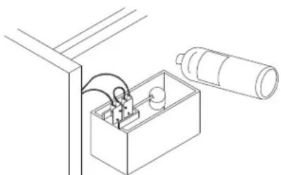
Use Metal Safe Ice Machine De-scaler, part number 000000084 (used to remove lime scale and mineral deposits).
Use Ice Machine Sanitizer part number 9405653 (used to disenfect, remove algae and slime).
Step 1 Remove front and top covers and set the toggle switch to the OFF position.
Step 2 Remove all ice from the bin.
Step 3 Turn off the ice making water supply and drain water from evaporator and reservoir.
Step 4 Remove the top cover from water reservoir.
Step 5 Follow the chart and premix de-scaler and water.
| Amount of Water | Amount of Metal Safe De-scaler - Part Number 000000084 |
| 1 gallon (4 Liters) 3 ounces (90 ml) | |
Step 6 Fill the evaporator and reservoir with de-scaling solution.
natural_image
Technical line drawing of an electrical enclosure with wiring and a cylindrical component (no text or symbols)Step 7 Move the toggle switch to the ON position. The ice machine will make ice with the de-scaling solution and deposit the ice in the bin. Add the remaining de-scaler/water solution as the water level in the reservoir drops.
NOTE: Do not allow the de-scaler/water level to drop below the minimum water level. The ice machine will discontinue the de-scaling cycle if the water float switch opens.
Step 8 After all of the de-scaler/water solution has been added, turn on the ice making water supply. Continue the freeze cycle for 10 minutes to remove the de-scaling solution from the water circuit.
Step 9 Place the toggle switch in the OFF position.
Step 10 Refer to Removal of Parts for De-scaling/Sanitizing and disassemble parts for hand de-scaling/sanitizing.
- Hand de-scale all parts.
- Rinse all parts with clear potable water.
- Sanitize all parts — do not rinse after sanitizing.
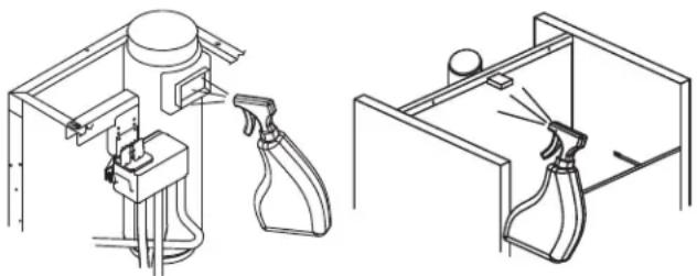
- Spray all interior bin surfaces with sanitizer (do not rinse sanitized areas).
- Spray evaporator discharge spout.
natural_image
Technical line drawings of a kitchen sink with spray gun and spray bottle (no text or symbols)Step 11 Reassemble ice machine.
Step 12 Turn off the ice making water supply.
Step 13 Refer to chart and premix water and sanitizer.
| Amount of Water Amount of Sanitizer | |
| 1 Gallon (4 L) Water 0.5 ounce (15 ml) |
Step 14 Fill the evaporator and reservoir with sanitizer/water solution.
Step 15 Move the toggle switch to the ON position. The ice machine will make ice with the sanitizer/water solution and deposit the ice in the bin. Add the remaining sanitizer/water solution when the water level in the reservoir drops.
NOTE: Do not allow the sanitizer/water level to drop below the minimum water level. The ice machine will discontinue the sanitizing cycle if the water float switch opens.
Step 16 After all of the sanitizer/water solution has been added to the reservoir, turn on the ice making water supply.
Step 17 Continue the freeze cycle for 30 minutes and then discard all ice produced.
Procedure to De-scale a Heavily Scaled Flake Ice Machines
Step 1 Remove front and top covers and set the toggle switch to the OFF position.
Step 2 Remove all ice from the bin.
Step 3 Turn off the ice making water supply.
Step 4 Remove the top cover from water reservoir.
Step 5 Refer to chart below:
Premix de-scaler with lukewarm water in a non-metallic container.
| Model | Water Reservoir Capacity | Mix De-scaler and Water Use Metal Safe Ice Machine De-scaler, part number 000000084 only | |
| De-scaler Water | |||
| UNF0200UFF0200UFP0200UFF0350UFP0350UNF0300UNP0300 | 14 oz (400 ml) 9 | oz (266 ml) 5 oz (148 ml) | |
| RFF0320RNF0320RFP0320RNF0620RNP0620RFF0620RFP0620 | 17 oz (500 ml) 1 | 1 oz (325 ml) 6 oz (177 ml) | |
| RNF1100RNP1100RFF1200CRFF1300 | 34 oz (1 L) 23 | oz (680 ml) 11 oz (325 ml) | |
| RNF2000CRFF2200CRFF2500 | 68 oz (2 L) | 46 oz (1.3 L) | 22 oz (650 ml) |
Step 6 Remove all water from the evaporator and water reservoir. Add the entire de-scaler/water solution and re-install the reservoir cover.
Leave the de-scaler/water solution in the evaporator for a minimum of 4 hours.
Step 7 Remove all de-scaler/water from the evaporator and water reservoir.
Step 8 Follow the Detailed De-scaling and Sanitizing procedures on page 25.
Removal of Parts for De-scaling/Sanitizing
Warning
Disconnect electric power to the ice machine at the electric switch box and wear rubber gloves and safety goggles (or face shield) while handling de-scaler or sanitizer.
Caution
Do not mix De-scaler and Sanitizer solutions together. It is a violation of Federal law to use these solutions in a manner inconsistent with their labeling.
- Turn off the water supply to the ice machine at the water service valve.
- Remove all components in the water flow path for de-scaling and sanitizing.
- Soak the removed part(s) in a properly mixed solution of de-scaler and water.
| Solution Type Water Mixed With | ||
| De-scaler 1 gal. (4 L) | 16 oz (500 ml) de-scaler Part Number 000000084 | |
- Use a soft-bristle brush or sponge (NOT a wire brush) to carefully de-scale the parts.
- Use the solution and a brush or sponge to de-scale all disassembled components and the inside of the bin.
- Rinse all de-scaled parts with clear water.
- Mix a solution of sanitizer and water.
| Solution Type Water Mixed With | ||
| Sanitizer 3 gal. | (11 L) | 2 oz (60 ml) sanitizerPart Number 9405653 |
- Soak the parts in the sanitizer/water solution for 10 minutes. Use the sanitizer/water solution and a sponge to sanitize all removed components and the inside of the bin. Do not rinse the sanitized parts.
- Continue with step 11 of the Detailed De-scaling/Sanitizing procedure.
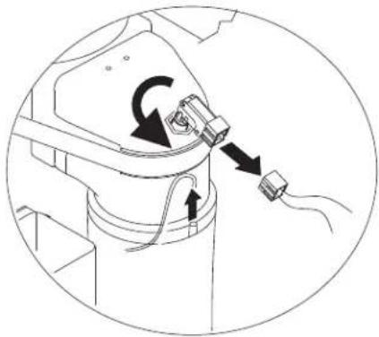
ICE CHUTE REMOVAL
RNF0620/RFF0620/RNP0620/RNF1020C/RNF1100/RNP1100 RFF1200C/RFF1300/RNF200C/RFF2200C/RFF2500 Only
Place the toggle switch in the OFF position, turn off the water supply and disconnect electrical power to the ice machine.
- Disconnect water supply.
- Remove water reservoir cover.
- Remove microswitch and bin thermostat from the ice chute.
- Remove retainer, ice chute elbow and ice chute.
natural_image
Diagram of a mechanical device with rotating components and directional arrows indicating motion (no text or symbols)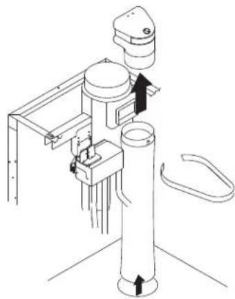
natural_image
Technical line drawing of a mechanical device with no visible text or symbolsAir-Cooled Condenser Cleaning
⚠ Warning
Disconnect electric power to the ice machine and the remote condenser at the electric service switch before cleaning the condenser.
A dirty condenser restricts airflow, resulting in excessively high operating temperatures and reduced ice production. Clean the condenser at least every six months.
Caution
The condenser fins are sharp. Use care when cleaning them.
- Clean the outside of the condenser with a soft brush or a vacuum with a brush attachment. Shine a flashlight through the condenser to check for dirt between the fins. If dirt remains, a method suitable to remove the contamination must be used to ensure air flow.
- Modular Units Only: Clean the washable filter with a mild soap and water solution.
Removal from Service/Winterization
- De-scale and sanitize the ice machine.
- Press the power button and turn off the ice machine.
- Turn off the water supply, disconnect and drain the incoming ice-making water line at the rear of the ice machine and drain the water trough.
-
Energize the ice machine, wait one minute for the water inlet valve to open and blow compressed air in both the incoming water and the drain openings in the rear of the ice machine to remove all water.
-
Press the power button and turn off the ice machine. Disconnect the electric power at the circuit breaker or the electric service switch.
-
Fill spray bottle with sanitizer/water solution and spray all interior food zone surfaces. Do not rinse and allow to air dry.
-
Replace all panels.
WATER-COOLED ICE MACHINES
- Perform steps 1-6.
- Disconnect the incoming water and drain line from the water-cooled condenser.
- Energize the ice machine in the freeze cycle. The increasing refrigerant pressure will open the water regulating valve.
- Blow compressed air through the condenser until no water remains.
- Replace all panels.
Section5
Troubleshooting
Checklist
If a problem arises during operation of your ice machine, follow the checklist below before calling service. Routine adjustments and maintenance procedures are not covered by the warranty.
| Problem Possible Cause To | Correct | |
| Ice machine does not operate. | No electrical power to the ice machine and/or condensing unit. | Replace the fuse/reset the breaker/turn on the main switch. |
| High pressure cutout tripping. Clean condenser | coil. (See Section 4) | |
| Power switch set improperly. Move the switch to the ON position. | ||
| Bin thermostat open or ice touching thermostat probe. | Adjust thermostat or remove ice. | |
| No water in reservoir. | No water to ice machine, plugged filter, float valve defective. | |
| Ice chute switch open. Check for ice or binding and close switch. | ||
| Low air temperature around ice machine. Air temperature must be at least 35^ ( 2^ ). | ||
| Gear motor runs and no ice is produced | Time delay has not expired. Wait 10 minutes for time delay to expire. | |
| High pressure cutout tripping. Clean condenser | coil and reset. | |
| Low pressure control open. Thaw evaporator and retest - Call for service. | ||
| Low Production | Due for normal maintenance. | Perform Detailed De-scaling & Sanitzing Procedure. (See Section 4) |
| Ice machine starts and stops without a full bin of ice. | Perform Detailed De-scaling & Sanitzing Procedure. (See Section 4) | |
THIS PAGE INTENTIONALLY LEFT BLANK
natural_image
Simple line drawing of a U-shaped pipe or tube with two square ends (no text or symbols)natural_image
Technical line drawing of an electrical enclosure with wiring and a cylindrical component (no text or symbols)natural_image
Technical line drawings of a spray gun and spray bottle in two different indoor setups (no text or symbols)natural_image
Technical diagram of a mechanical assembly with directional arrows indicating motion (no text or symbols)
natural_image
Technical line drawing of a mechanical device with no visible text or symbolsFuncionamiento de UFF0200/UNF0200/UNP0200/UFF0350/UFP0350/UNF0300/UNP0300 79
Funcionamiento de RFF0320/RNF0320/RFP0320/RNP0320 80
Funcionamiento de RNF0620/RFF0620/RNP0620/RFP0620/RNF1020C/RNF1100/RNP1100/
RFF1200C/RFF1300/RNF2000C/RFF2200C/RFF2500 80
Sección 4
Mantenimiento
natural_image
Simple line drawing of a U-shaped pipe with two square ends (no text or symbols)Funcionamiento de UFF0200/UNF0200/UNP0200/UFF0350/UFP0350/UNF0300/UNP0300
natural_image
Line drawing of an electrical circuit setup with a box, wires, and cylindrical components (no text or symbols)natural_image
Technical line drawings of a kitchen sink with spray gun and spray bottle (no text or symbols)natural_image
Diagram of a mechanical device with rotating components and directional arrows indicating motion (no text or symbols)
natural_image
Technical line drawing of a mechanical device with no visible text or symbols- Flake & Nugget Ice Machines RFF, RNF, UFF, UNF, RFP, RNP, UFP, UNP Models
- Installation, Operation and Maintenance Manual
- Safety Notices
- Read these precautions to prevent personal injury:
- Definitions
- ! DANGER
- Warning
- ! Caution
- Notice
- ▲Warning
- Follow these precautions to prevent personal injury during installation of this equipment:
- DANGER
- Follow these flammable refrigeration system requirements during installation, use or repair of this equipment.
- ▲ Warning
- Follow these electrical requirements during installation of this equipment.
- Follow these precautions to prevent personal injury while operating or maintaining this equipment:
- Follow these precautions to prevent personal injury during use and maintenance of this equipment:
- Table of Contents
- Section 1 General Information
- Section 2 Installation Instructions
- Section 3 Operation
- Section 4 Maintenance
- Section 5 Troubleshooting
- Section1
- GeneralInformation
- Model Numbers
- Caution
- Adapters
- RFF2500 BIN ADAPTER INSTALLATION
- ⚠ Warning
- PERSONAL INJURY POTENTIAL
- Warranty Information
- Arctic Pure Water Filter System
- Manitowoc De-scaler and Sanitizer
- LEGS
- Location of Ice Machine
- Installation Requirements
- Water and Drain Requirements
- POTABLE WATER REQUIREMENTS
- DRAIN CONNECTIONS
- COOLING TOWER APPLICATIONS
- Electrical Service
- VOLTAGE
- Important
- FUSE/CIRCUIT BREAKER
- GROUND FAULT CIRCUIT INTERRUPTER
- MINIMUM POWER CORD SPECIFICATIONS
- FOR UNITED KINGDOM ONLY
- Maximum Breaker Size & Minimum Circuit Amperage Chart
- USAGE WITH NON-MANITOWOC CONDENSING UNITS
- Factory Equipment Refrigeration Amounts
- ICE MACHINE HEAD SECTION
- Potential Personal Injury Situation
- Refrigeration Line Set Installation Remote Condensing Unit Only
- GENERAL
- Step 1 Verify Ice Machine and Remote Condensing Unit Locations Are Within Guidelines
- Roof/Wall Penetration
- Step 2 Route Refrigeration Tubing
- LINE SET LENGTH
- SUCTION LINE OIL TRAPS
- Step 3 Lengthening or Reducing Line Set Lengths
- Step 4 Connecting the line set
- Connect the Line Set to the Remote Condensing Unit
- Connect the Line Set to the Ice Machine Head Section
- Step 5 Pressure Test and Evacuate Line Set and Ice Machine Head Section
- Step 6 Open the valves and leak check the refrigeration system prior to startup of the ice machine
- Step 7 Insulation Requirements
- Installation Check List
- Additional Checks for QuietQube® Models
- Section3
- Operation
- Bin Thermostat and Evaporator Low Temperature Safety Adjustment Chart
- UFF0200/UNF0200/UNP0200/UFF0350/UFP0350/UNF0300/UNP0300 Operation
- RFF0320/RNF0320/RFP0320/RNP0320 Operation
- RNF0620/RFF0620/RNP0620/RFP0620/RNF1020C/RNF1100/RNP1100/RFF1200C/RFF1300/RNF2000C/RFF2200C/RFF2500 Operation
- Section4 Maintenance
- Interior De-scaling and Sanitizing
- DETAILED DE-SCALING/SANITIZING PROCEDURE
- HEAVILY SCALED DE-SCALING PROCEDURE
- Exterior Cleaning
- Detailed De-scaling and Sanitizing Procedure
- Procedure to De-scale a Heavily Scaled Flake Ice Machines
- Removal of Parts for De-scaling/Sanitizing
- ICE CHUTE REMOVAL
- Air-Cooled Condenser Cleaning
- Removal from Service/Winterization
- WATER-COOLED ICE MACHINES
- Section5
- Troubleshooting
- Checklist
- Sección 4
- Mantenimiento
- Funcionamiento de UFF0200/UNF0200/UNP0200/UFF0350/UFP0350/UNF0300/UNP0300
Brand : Manitowoc
Model : RFP0320A
Category : Ice machine