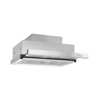
DEF6800.0E - Basket Küppersbusch - Free user manual and instructions
Find the device manual for free DEF6800.0E Küppersbusch in PDF.


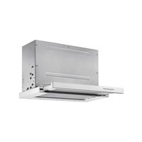
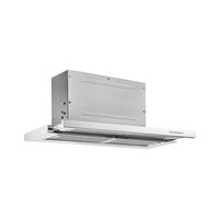
| Product type | Extractor hood |
| Brand | Küppersbusch |
| Model | DEF6800.0E |
| Width | 600 mm / 900 mm |
| Depth | 300 mm |
| Height | 183 mm / 273 mm |
| Power supply | See rating label (according to model) |
| Number of speeds | 6 speeds + intensive (limited to 7 min) |
| Lighting | Integrated LED |
| Filter type | Washable metal filters + optional active carbon filter |
| Minimum installation height | 60 cm (electric hob) / 65 cm (gas hob) |
| Maximum exhaust duct length | 4 meters with maximum 2 bends |
| Filter cleaning | At least once a month, in dishwasher or hot water |
| Charcoal filter replacement | Every 3 to 6 months |
| Safety | Automatic shut-off after 7 min in intensive speed; power cut required before maintenance |
| Timer function | Yes, adjustable from 5 to 30 minutes |
| Interchangeable front panel | Yes, to match the furniture decor |
| Evacuation type | External (recommended) or recirculation with charcoal filter |
Frequently Asked Questions - DEF6800.0E Küppersbusch
User questions about DEF6800.0E Küppersbusch
0 question about this device. Answer the ones you know or ask your own.
Ask a new question about this device
Download the instructions for your Basket in PDF format for free! Find your manual DEF6800.0E - Küppersbusch and take your electronic device back in hand. On this page are published all the documents necessary for the use of your device. DEF6800.0E by Küppersbusch.
USER MANUAL DEF6800.0E Küppersbusch
natural_image
Simple line drawing of a tower with base and top (no text or symbols)DEF6800.0
DEF9800.0
Please read the users and installation instructions carefully before installation of the appliance and before starting to use it.
Carefully read the instructions before installing and using the equipment. The manufacturer is not liable for improper installation and use of the equipment that may cause injuries and damage. Always keep the instructions at hand, so they can be easily referred to during use.
Children and Vulnerable people safety
- This appliance is not intended for use by persons (including children) with reduced physical, sensory or mental capabilities, or lack of experience and knowledge, unless they have been given supervision or instruction concerning use of the appliance by a person responsible for their safety.
- Children should be supervised to ensure that they do not play with the appliance.
General Safety
- There shall be adequate ventilation of the room when the range hood is used at the same time as appliances burning gas or other fuels (not applicable to appliances that only discharge the air back into the room).
- Do not flambé under the range hood.
- CAUTION: Accessible parts may become hot when used with cooking appliances.
Installation
- The electric system must be equipped with a means for disconnection, with a contact separation in all poles that provides full disconnection under overvoltage category III conditions, in accordance to the wiring rules.
- If a plug is used for the electric connection, then it must be accessible after installation.
- The air must not be discharged into a flue that is used for exhausting fumes from appliances burning gas or other fuels
(not applicable to appliances that only discharge the air back into the room).
- The lower part of the extractor must be located at a minimum height of 60 cm above the hob for electric cookers and 65 cm for gas cookers. If the instructions of a gas cooker indicate a greater distance these must be observed.
- Before installing the extractor consult the local rules and regulations in force with respect to the discharge of air and fumes.
- When the extractor is working at the same time as other non-electrical cooking equipment, the outlet air pressure must not exceed 4 Pa (4x10⁻⁵ bar).
- Before connecting the extractor to the mains, check that both the voltage and the frequency conform to that shown on the characteristics label located inside the extractor.
- To achieve optimum performance the length of the outlet hose should not exceed 4 meters, or include more than two 90^ angles (elbows).
- Although venting to the outside is recommended, activated carbon filter may be used to allow the gas to be returned to the kitchen through the outlet pipe.
- NOTE: For more Installation information, refer to the end of this user manual.
Cleaning
- There is a fire risk if cleaning is not carried out in accordance with the instructions.
- Do not allow grease to accumulate in any part of the extractor, especially in the grease filters as this COULD PRODUCE A FIRE RISK!
- The grease filters and the internal part of the extractor must be cleaned at least once a month depending on how often
the extractor is used. Note that grease is deposited in the extractor when cooking, whether it is switched on or not.
- We recommend the use of gloves and caution when cleaning the inside of the extractor.
Repairs
- If the supply cord is damaged, it must be replaced by the manufacturer, its service agent or similarly qualified persons in order to avoid a hazard.
- Do not switch on the extractor if the supply cord is worn or has cuts or if there are signs of deterioration around the control panel.
- If the LED module is malfunctioning, it must be replaced by the manufacturer, its service agent or similarly qualified persons in order to avoid a hazard.
- If the extractor stops working or functions abnormally, unplug it from the mains and contact the technical service.
Description of the appliance (Fig. 1-5)
A Motor push control that allow 6 speeds to be selected
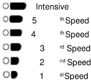
bar
| Category | Intensive | Speed | |---|---|---| | O | 5 | th Speed | | O | 4 | th Speed | | O | 3 | rd Speed | | O | 2 | nd Speed | | O | 1 | st Speed |B Lamp push control

C Lighting by means of lamps
D Filters located over cooking area, easily withdrawn for cleaning
E Extractable group that allows a greater gas capture area
F Possibility of incorporating activated charcoal filter (Fig. 2)
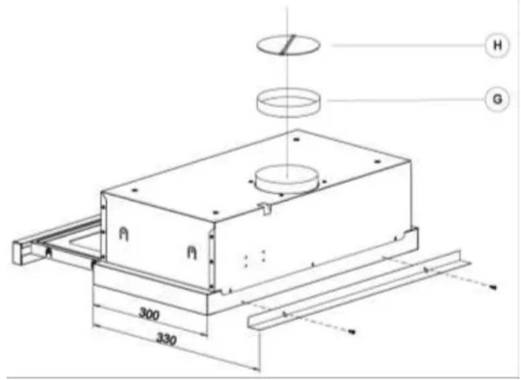
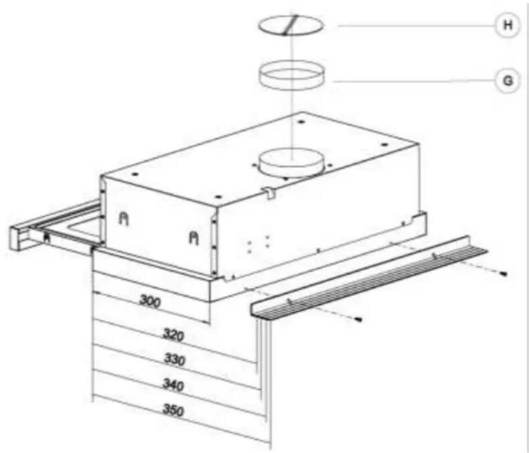
G-H Anti return tabs to be located in the outlet mouth, locating their ends in the holes provided (Fig.5).
Instructions for use
To achieve better extraction, we recommend switching on the extractor a few minutes before starting to cook (3 - 5 minutes) so that the air flow is continuous and stable when extracting the fumes.
Likewise, keep the extractor switched on for a few minutes when cooking is complete to allow all fumes and odours to be expelled.
Operating settings
- When the tray is opened, the hood starts operating at speed 1.
- To increase speed gradually, press the “☐” key as many times as necessary, until maximum speed is set.
- The sixth speed is timed, so the cooker hood will automatically revert to the third speed after seven minutes.
- To reduce the speed gradually, press the "√" key as many times as needed.
- To turn off the cooker hood directly at any speed, keep the "√" key pressed for 3 seconds.
Programming stop delay timer
- Programming Timer
a. Open Tray with motors switched on or off
b. Maintain "A" key pressed until all LEDs flicker quickly.
c. Press "V" or "A" keys to select aspiration time. Each LED represents 5
Cleaning and maintenance
Before carrying out any cleaning or maintenance activities, ensure that the extractor is disconnected from the mains.
To carry out cleaning and maintenance, follow the Safety Instructions.
Fire risk exists in case that cleaning does not take place according to the instructions.
Filter cleaning
To withdraw the filters from their locations release the anchoring points. Clean the filter, either by putting it in the dishwasher (see notes) or leaving it standing in hot water to simplify the removal of grease or, if wished, by means of special sprays (protecting the non metallic parts). Once clean, leave it to dry.
minutes of operating time. The maximum operating time is 30 minutes (the LED corresponding to the intensive speed starts flickering fast).
d. 5 seconds after pressing the keys, the LED corresponding to the time stops flickering fast and the LED corresponding to the selected speed starts flickering slowly.
e. In stop delay timer Mode, speed can be adjusted by pressing "V" or "A" keys.
- Cancellation of Stop Delay Timer:
Maintain "V" key pressed until the motors switch off, or close the tray.
Lighting
The lighting can be switched on and off by pressing the key "☐".
When tray is opened, the lighting is switched on or off, depending on how it was used the last time.
Attention: the cooker hood will not work until the main filter was reinstalled.
Notes: cleaning in the dishwasher with aggressive detergents may blacken the surface of metallic parts, without this affecting its gas retaining properties.
N.B. The filter must be cleaned at least once a month depending on how often the extractor is used. It must be remembered that grease is deposited in the extractor when cooking, whether it is switched on or not.
Cleaning of the extractor body
The use of warm (40°C approx.) soapy water is recommended. A cloth moistened in this water is used for cleaning the extractor, paying
special attention to the grids. Afterwards, dry it using a lint-free cloth.
Note:
- Never use metallic scouring pads or abrasive products that could damage the surface.
- Do not use scrapers with metallic surfaces such as knives, scissors etc.
Activated charcoal filter
- To install the charcoal filter, the motor anchorage is made to coincide with the
anchor points of the activated charcoal filter and turn it clockwise.
- The carbon filter lasts from three to six months depending on the particular conditions of use.
- The activated carbon filter can neither be washed nor regenerated. Once it is exhausted, it must be changed.
- To replace exhausted filters with new ones, withdraw the old one in the reverse order to that of installation.
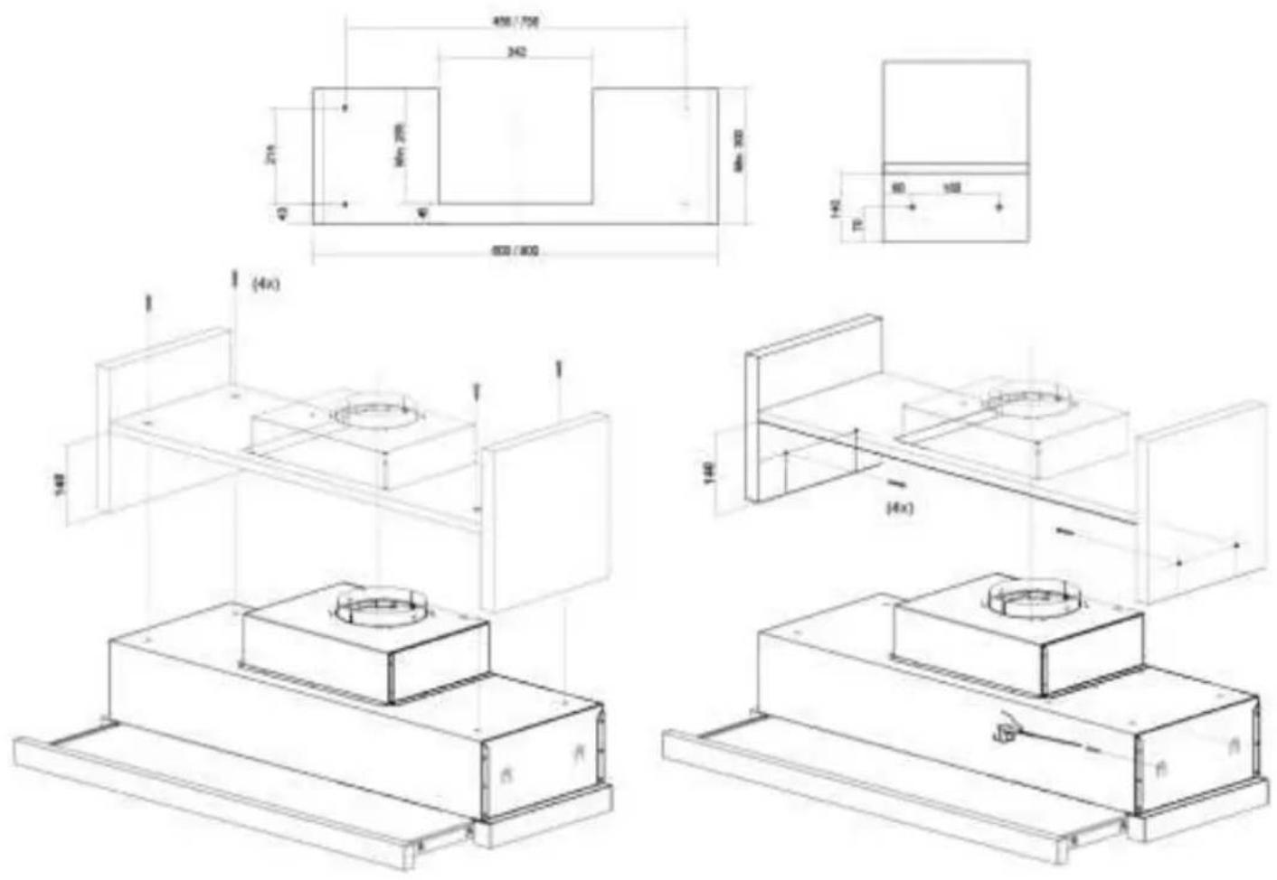
Tecnical Information (Fig. 4)
Dimensions:
$$ \text { Width } = 6 0 0 / 9 0 0 \mathrm{mm} $$
$$ \text { Depth } = 3 0 0 \mathrm{mm} $$
$$ \text { Height } = 1 8 3 / 2 7 3 \mathrm{mm} $$
Electrical characteristics:
REFER TO RATING PLATE
Installation
To fix the cooker hood please choose one of the following options:
a) Fixing to the upper part of the furniture:
Figure 4 must be used where the position of the holes is indicated.
b) To the internal side of the furniture:
When the body hood fits within the furniture, fasten with two screws on each side from the inside of the body hood, using their side holes.
The lower part of the extractor must be located at a minimum height of 60 cm above the hob for electric cookers and 65 cm for gas cookers. If the instructions of a gas cooker indicate a greater distance these must be observed.
To achieve optimum performance the length of the outlet hose should not exceed 4 meters, or include more than two 90° angles (elbows). Although venting to the outside is recommended, activated carbon filters may be used, which allow the gas to be returned to the kitchen through the outlet pipe.
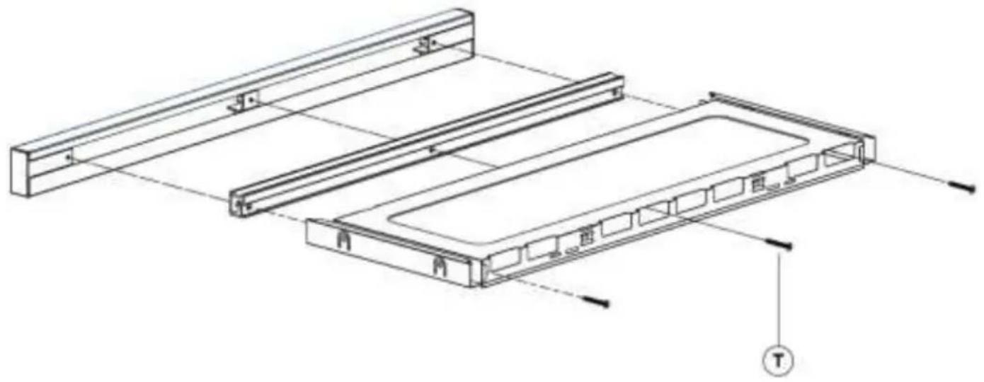
If you wish to exchange the front for one matching the kitchen units, follow the following instructions (Fig. 3):
- Withdraw the movable group.
- Remove the screws (T) that support the front.
- Install the new front fixing it with the same screws that held the old one.
If something does not work
Before seeking technical assistance carry out the following checks first:
| Defect | Possible cause | Solution |
| The extractor does not work | The cable is not connected | Connect the mains cable |
| No current is reaching the plug | Revise/repair the electricity circuit | |
| The extractor does not blow enough or vibrates | Filter saturated with grease | Clean or substitute the filter |
| Outlet obstructed | Eliminate obstructions | |
| Inadequate air conduit | Contact the installer and follow instructions of this manual | |
| The lamps do not light | Lamp broken | Contact the Customer ServiceILCOS D Code: DSL-6-S-500 |
Special U.K. Requirements
Height above gas hob: 75 mm minimum.
This appliance must be connected by a competent person, using fixed wiring via a DOUBLE POLE SWITCHED FUSED SPUR OUTLET.
Special Australia Requirements
This appliance is not intended for use by young children or infirm persons without supervision.
Young children should be supervised to ensure that they do not play with the appliance.
Electrical connection
We recommend that the appliance is connected by a qualified electrician, who is a member of the N.I.C.E.I.C. and who will comply with the I.E.E. and local regulations.
Should the colour of the wires in the mains lead for the appliance not correspond with the coloured markings identifying the terminal in your spur box proceed as follows:
The wire which is coloured blue must be connected to the marked N (Neutral) or coloured Black.
The wire which is coloured brown must be connected to the marked L (Live) or couloured Red
Where avialable (see installation), the wire which is coloured yellow/green must be connected to the marked 🌐 or coloured Yellow/Green.
If the cooker hood is installed for use above a gas appliance then the provision vor ventilation must be in accordance with the Gas Safety (Installation & Use) Regulations 1984 and the relevant Building Regulations. Detailed recommendations are contained in the following British Standard Codes of Practice BS6172, BS5440 and BS6891 Current Edition.
Environmental protection
Disposal of the packaging
The packaging bears the Green Point mark.
Dispose of all the packaging materials such as cardboard, expanded polystyrene and plastic wrapping in the appropriate bins. In this way you can be sure that the packaging materials will be re-used.
Disposal of equipment no longer used

According to European Directive 2012/19/EU on the management of waste electrical and electronic equipment (WEEE), home electrical appliances should not be put into the normal systems for disposal of solid urban waste.
Outdated appliances should be collected separately to optimise component material
recovery and re-cycling rates and to prevent potential harm to human health and the environment. The symbol of a rubbish container superimposed by a diagonal cross should be put on all such products to remind people of their obligation to have such items collected separately.
Consumers should contact their local authorities or point of sale and request information on the appropriate places to leave their old home electrical appliances.
Before disposing of your appliance, render it non-usable by pulling out the power cable, cutting this and disposing of it.
Programmering stop delay time
1. Programming Timer
3
natural_image
Technical line drawing of a mechanical assembly with two parallel plates and a central housing, showing internal components and alignment lines (no text or symbols)4
5
Küppersbusch

- Children and Vulnerable people safety
- General Safety
- Installation
- Cleaning
- Repairs
- Description of the appliance (Fig. 1-5)
- Instructions for use
- Operating settings
- Programming stop delay timer
- Cleaning and maintenance
- Filter cleaning
- Lighting
- Cleaning of the extractor body
- Note:
- Activated charcoal filter
- Tecnical Information (Fig. 4)
- If something does not work
- Special U.K. Requirements
- Special Australia Requirements
- Electrical connection
- Environmental protection
- Programmering stop delay time
- Programming Timer
- Küppersbusch
Brand : Küppersbusch
Model : DEF6800.0E
Category : Basket