
PLE 64X - Hob CANDY - Free user manual and instructions
Find the device manual for free PLE 64X CANDY in PDF.


User questions about PLE 64X CANDY
0 question about this device. Answer the ones you know or ask your own.
Ask a new question about this device
Download the instructions for your Hob in PDF format for free! Find your manual PLE 64X - CANDY and take your electronic device back in hand. On this page are published all the documents necessary for the use of your device. PLE 64X by CANDY.
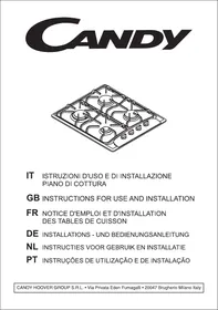
USER MANUAL PLE 64X CANDY
- ALLACCIAMENTO CON TUBO FLESSIBLE IN ACCIAIO
* INSTALLATION 18
Before installing the hob : 18
For installation 18
Changing the gas type 19
Changing the jets 19
Building - in : 20
Gas connection 21
Electrical connection 22
4 Hotplates 22
Gas and Mixed 23
Regulating the flame 23
- USING THE APPLIANCE 24
The gas burners 24
Igniting and setting the burner 25
Use Of Cooktop Electrical Plates. 25
Cleaning 27
General maintenance 27
The pan support 28
*TECHNICAL DATA 28
*AFTERCARE 29
UNPACKING THE APPLIANCE
Inside the appliance, you will find :
- A plastic bag containing :
- the new jets fort he gas modification, if required,
- a conical connector with seal for the gas connection,
- the fixing brackets with screws required for installing the hob in the worktop.
TO GET THE BEST FROM YOUR APPLIANCE, PLEASE READ THE FOLLOWING CAREFULLY.
Please keep the operating and installation instructions in a safe place for future reference. Before fixing the hob, note the serial number of the appliance just in case you should require future repairs from our after sales service organisation at some time in the future.
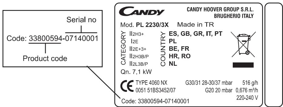
Rating plate (located under the lower casing of the hob)

WARNING
- All accessible parts of the hob will become hot while in operation. Always keep children away from it.
- The hob should be given a quick clean after each use, to avoid the accumulation of spillages and grease. If spillages are not removed, they will harden, and could cause the production of smoke and unpleasant smells.
- When cooking with fats or oils, never leave gas burner unattended. Overheated fats or oil can quickly catch fire.
- This appliance is not intended for use by persons (including children) with reduced physical, sensory or mental capabilities, or lack of experience and knowledge, unless they have been given supervision or instruction concerning use of the appliance by a person responsible for their safety.
Children should be supervised to ensure that they do not play with the appliance. - Isn't allowed to remove the knobs for the cleaning because the shafts aren't protected against accidental contact with basic insulation and because if the knob s are removed, water could enter in the appliance and come in contact with live parts or reduce the distance.

WARNING
Installing a domestic appliance can be complicated operation which if not carried out correctly, can seriously affect consumer safety.
It is for this reason that the task should be undertaken by a professionally qualified person who will carry it out in accordance with the technical regulations in force.
In the event that this advice is ignored and the installation is carried out by an unqualified person, CANDY declines all responsibility for any technical failure of the product whether or not it results in damage to goods or injury to individuals.

Before installing the hob :
1 Make sure that the appliance is compatible with the gas supply source.
The hob is pre-set in the factory to work with the type of gas shown on the packing and the plate attached to it.
Natural gas G 20- 20 mbar/ G25- 25 mbar . main gas.
2 If necessary, adapt the hob for use with another type of gas: if the hob must be used with another type of gas than the gas pre-set in the factory, it is necessary to adapt the hob gas burners (page 19). The procedure for adaptation consists of:
. fitting the correct jets to ensure nominal delivery.

For installation :
Built-in hob (page 20)
Make the gas connection according to type of gas to be used: based on the gas to be used. Choose the appropriate gas connection (page 21).
⑤ Make the hob electrical connection according to instructions. (page 22).
Adjusting the minimum flame of the taps: if necessary, adjust the minimum flame of the taps by turning the by-pass screw (page 23).
All modification concerning the hob gas setting must be indicated on the rating plate of the hob.
Changing the gas type :
The calorific power output and gas pressure will vary according to the gas supply. Burner setting must be carried out once the gas and electrical installation is complete.
When changing gas type, you must follow the procedure below :
. fit the correct jets,
adjust the minimum flame on the taps (see page 23).
| GAZ/GAS | G20 | G25 | G30 | G31 | |
| 20 mbar | 25 mbar | 29 mbar | 37 mbar | ||
| CAT. II2E+3+ | FR-BE | α | X | X | |
| CAT. II2H3+ | ES-GB-GR-IT-PT | α | X | X | |
| CAT. II2H3B/P | HR-RO | α | X | ||
| CAT. II2L3B/P | NL | α | X | ||
| CAT. I2E | PL | α |
= Factory setting: Natural gas = G20-20 mbar/G25-25 mbar
X : Gas setting possible according to installation Butane gas G30-29 mbar or
Propane gas G31-37 mbar

Changing the jets :
The gain access to the jets, remove the pan supports, and remove the burner cap and body, Take a spanner and unscrew the jet.
According to the table below, fit the correct jet for the type of gas to be used,
Secure the jet tightly,
Place the burner body, cap and pan support.

Each jet is designated by size.
| HOB BURNERS | ||||||||
| front right | rear | front left | ||||||
| auxiliary | semi-rapid | rapid | ||||||
| Gas | mbar | Jet | kW | Jet | kW | Jet | kW | |
| * | G 20 | 20 | 0.83 | 1.00 | 1.00 | 1.70 | 1.20 | 2.70 |
| G 25 | 25 | 0.83 | 1.00 | 1.00 | 1.70 | 1.20 | 2.70 | |
| G 25 | 20 | 0.90 | 1.00 | 1.10 | 1.70 | 1.35 | 2.70 | |
| G 30 | 29 | 0.50 | 1.00 | 0.65 | 1.70 | 0.85 | 2.70 | |
| G 31 | 37 | 0.50 | 1.00 | 0.65 | 1.70 | 0.85 | 2.70 | |
| G 30 | 50 | 0.45 | 1.00 | 0.60 | 1.70 | 0.70 | 2.70 | |
| G 31 | ||||||||
| G 30 | 37 | 0.50 | 1.00 | 0.65 | 1.75 | 0.85 | 2.95 | |
| G 31 | ||||||||
| G 20 | 25 | 0.83 | 1.10 | 1.00 | 1.85 | 1.20 | 2.95 | |
| G 25.1 | 25 | 0.83 | 1.00 | 1.00 | 1.70 | 1.20 | 2.65 | |
| G 2.350 | 13 | 1.10 | 1.00 | 1.35 | 1.70 | 1.70 | 2.70 | |
| G 27 | 20 | 0.90 | 1.00 | 1.10 | 1.70 | 1.35 | 2.70 | |
| kW = power | ||||||||
| * Factory setting: G 20-20 mbar/G 25-25 mbar | ||||||||


The body of the hob is fitted with 4 location holes to take the fixing brackets that secure the hob in the unit. Place 4 fixing brackets in such a way that the hob is placed perfectly in the support unit.

The hob can be built-in; it is in class 3 (in compliance with gas regulations EN30.1.1); adjoining furniture should not be higher than the level of the hob.
This appliance is not connected to an evacuation device for the products of combustion. It must be installed and connected in compliance with the norms in force in the country of installation. Particular attention should be given to the availability of ventilation. The turnover of air necessary for combustion is a minimum of 2m3/h per kW of power.
Gas connection should be carried out in compliance with the norms in force in the country of installation. A stop tap, a regulator valve or a release valve for propane gas, should be fitted to the gas supply pipe. Use only taps, regulators valves, connectors and flexible hoses with the official mark of approval of the country of installation.
Built-in appliance
Butane Rigid-Flexible pipe with mechanical connectors (1) -
Propane Rigid-Flexible pipe with mechanical connectors (1) -
Natural Rigid-Flexible pipe with mechanical connectors (1) -
(1) on condition that the hose is accessible along the whole of its length it should be located so it cannot be reached by naked flame or affected by combustion gases. Neither should it be near hot parts of the hob nor anywhere where hot spillages could affect it.
(2) POSSIBLES MEANS CONNECTION :
Fit the appliance with the conical gas adaptor.
Conical gas adaptor

* CONNECTION BY RIGID PIPE
Connect directly to the threaded end of the inlet pipe.
* CONNECTION BY FLEXIBLE PIPE WITH MECHANICAL CONNECTOR
Screw the nuts of the flexible pipe directly on to the inlet pipe at one end and the gas supply stop tap at the other.
We recommend this type of connection.
ELECTRICAL CONNECTION
Cable connection should be done by Autorited service according to following instructions.
The electrical connection must be made according to the standards and regulations in force. Before making the electrical connection, check the following:
- Is the capacity of the electrical connections and safety fuses in the building sufficient to cope with the load of the appliance? (Check with the adhesive info label)
- Does the electricity supply line have an earth connection conforming with the standards in force?
A proper earth connection must exist in your home. If there is not a proper earth connection at your home, please apply to an authorized technician to deal with this problem.
- Is the socket or the multi-pole switch at a easily reachable point after the installation of the appliance?
- A plug conforming to standards should be connected to the mains cable and the cable should be inserted into a safe socket.
- A multi-pole switch must be used between the appliance and the electricity line if a direct electrical connection to the appliance is required. (It must comply with standards and be appropriate for the load)
The green-yellow ground cable must not be interrupted by a switch. The brown phase cable must always be connected to the phase line of the mains.
The power line must be positioned so that it is not exposed to temperatures higher than 50°C
- When the power cable must be changed only by authorized people, a cable with a cross section appropriate to the indicated power must be used. The green-yellow ground cable should be approximately 2 cm longer than phase and neutral cables.
- Check the electrical heaters by switching them on for 3 minutes, after having completed the connection.
- The manufacturer will not accept responsibility for damages arising due to non-compliance with the safety standards.

4 HOTPLATES
These hobs are delivered without cable. For connection, cable type and section referred to the table.
| Monophase 220-240 v~ | Three-phase 380-415V2N~ | ||||
| Fuse | 25 A | 2 x 16 A | |||
| Cable - Section Cable - Type | 3 G 2.5 mm² H05VV-F | 4 G 1.5 mm² H05VV-F | |||
| 3 | N | 4 | 3 | N | |
| 2 | PE | 5 | 2 | L2 | |
| 1 | L1 | 1/2 | 1 | PE | |
| L1 : Phase shunt 1-2 4-Neutral T-Earth | 1-Phase 2-Phase 4-Neutral T-Earth | ||||

These hobs are delivered with cable.
- Connection is exclusively envisaged under tensions of 220-240V. Between phases or between phases and neutral.
- Connect 10/16 amperes to an outlet.
- The eventual replacement of the supplying cord must be carried on by the After Sales Service or by an agreed engineer, with a cord whose characteristics must be similar to the original one:
-For the 4G hobs supplying cord type H05VV-F (section 3G0.75mm2
- For the 3G+E hobs, the rated current is 8.6A. Supplying cord type H05VV-F (section 3G 1mm²)
- For the 2G+2E hobs, the rated current is 13.6A. Supplying cord type H05VV-F (section 3G 1.5mm²)

Regulating the flame :
* Setting idle flame :
If you have changed the type of gas, it is important to verify the flame stability at the minimum regulation.
"Gaing Access to the by-pass screw"
To gain access to hob burner by-pass screws, remove the knobs from the control panel.

Never loosen the others screws!

REGULATING THE MINIMUM FLAME ON THE HOB BURNER
a) Natural gas :
- simply loosen the screw.
- switch on the burner and turn O the knob to minimum.
- Turn the by-pass screw until a low flame is visible. Turn the control knob from minimum to maximum position to check that it is satisfactory.
b) Butane-propane gas :
The by-pass screw should be screwed fully home, without being locked.
The gas burners :
THE RAPID BURNER has a power rating of 2,7 kW. It is situated on the front left of the hob. :
it is ideal for stewing.
THE SEMI-RAPID BURNER has a power rating of 1,7 kW. It is situated on the rear of the hob :
it is ideal for sauces and slow cooking.
THE AUXILIARY BURNER has a power rating of 1 kW. It is situated on the front right of the hob :
use this small burner for small pans.
For a proper use of the the burners, choose pans which match the dimensions given below:
- Rapid 2,7 kW
from 16 to 18 cm
- Semi-rapid 1,7 kW
0 12 cm
- Auxiliary 1 kW
0 10 cm
SOME TIPS......
- Pans with curved, ridged or warped bottoms are not recommended.
- Avoid boiling food too intensely. Food is not cooked any more quickly this way. In fact, it is subjected to severe agitation, which may cause the food to lose some of its flavour.
- To save gas, make sure that the flames do not overlap the bottom of the pan.
- Do not use the gas burner with an empty pan.
RECOMMENDATIONS : When the burners are not in service, the general gas supply tap should be turned off.
Igniting and setting the burner :
Each burner is fitted with automatic ignition. The ignition can be made with one hand, while you have the pan in the other hand.

USE :
- Turn on the gas tap,
- A symbol next to each control knob indicates which burner is lit.
example:front left burner)
Please note :
. If there is a power cut, the burner can be ignited by pressing in and turning the knob to position "high flame" and holding a naked flame to the burner.
For models fitted with a safety tap (which cuts-off the flow of gas if the flame is accidentally extinguished) the burners are ignited ad described above, but care must be taken to keep the knob pressed in for 5 or 6 seconds after the flame is ignited.
After this time, needed by flame failure device to activate, the flame will be permanent.
USE OF COOKTOP ELECTRICAL PLATES

Turn the knob to the position for the required temperature of the hot plate. The indicator light of the hot plate will come on and the hot plate will start to heat.
When cooking is completed, turn the knob to the "O" position. (Figure 2). Do not leave the hot plate turned on without a pan on it. The diameter and the base of the pan you use is critical. The maximum diameter of the pan base is 14cm and the base should be flat.
Leave the hot plate to heat up for 5 minutes before placing a pan on it the first time you use it. This will allow the heat resistant coating of the plate to harden due to burning.
Use a wet cloth and detergent for cleaning the hot plates. Do not remove food residues from the hot plates with a knife or any other hard, sharp object.
Turn on the hot plate for a few moments to dry it after cleaning. However, it must never be left on for more than a few moments without a pan on top.
| Position | Power (Watt) | Power (Watt) | Explanation |
| 0 | 0 | 0 | Off |
| 1 | 100 W | 135 W | Heating |
| 2 | 180 W | 220 W | Cooking at low temperature |
| 3 | 250 W | 300 W | Cooking at low temperature |
| 4 | 500 W | 850 W | Cooking, Roasting, Boiling |
| 5 | 750 W | 1150 W | Cooking, Roasting, Boiling |
| 6 | 1000 W | 1500 W | Cooking, Roasting, Boiling |
Suitability of Cooking Pans
Keep in mind that larger pans have larger heating surfaces.
This will help them to cook the food faster than pans with smaller heating surfaces.
Always use pan sizes proportionate to the amount of the food to be cooked. In order to prevent splashing, do not use very small pans, especially for foods with excess liquid. If you use excessively large pans for quick cooked foods, sausages and liquids will stick and residues will remain attached to the pan after being emptied.
Closed pans and baking trays or moulds are suggested for cooking sweets. Splashed sugar and juices from an open pan may stick to the cooker surface and will be difficult to remove.


This is especially important for pans used for roasting or pressurized cooking at high temperature.
Do not leave burners unattended without a pan or with an empty pan on top.
Check the suitability of cooking pans with respect to the following criteria;
They should be heavy.
They should completely cover the burner surface; they may be a little bigger but no smaller.
Base surfaces should be completely flat and fit well on the cooking surface.
- For the best use of the electric hotplates and to minimize energy consumption, only pans with smooth flat bases should be used. The size of the pan should be as close as possible to the diameter of the hotplate, and never smaller. The base of the pan should be dry and spillage should be avoided. Empty pans must not be left on the plates, and the plates should not be left switched on without a pan.
Before cleaning or removing the hob. It is imperative to:
- disconnect the hob from the mains supply,
- let all parts of the hob cool down.
Never use :
Harsh abrasives, scouring pads or sharp objects to clean the hob.
A steam cleaner is not to be used.

General maintenance :
THE HOB
-
ENAMELLED STEEL HOB : when the hob has cooled completely, simply clean the enamelled hob with soapy water, rinse and wipe with a clean dry cloth. If you clean the enamelled hob when it is hot, you may tarnish it.
-
STAINLESS STEEL : clean with soapy water, rinse and dry. You can use a special product to clean stainless steel which is available from various retail outlets.
THE KNOBS-
Only clean with soapy water rinse and dry well
THE GAS BURNERS
For cleaning, it is recommended to remove all greasy or burnt deposits with ammonia based products or usual cleaning products.
- The burner cap or ring : it is simply placed on the burner.
Remove the pan support, the burner cap and clean it with a slightly soapy sponge. Rinse and dry.
Do not immerse it in cold water when it is hot, this will prevent the enamel cracking as a result of thermal shock.
- The burner body : regular cleaning will maintain the appliance original appearance. Clean with a soapy sponge, rinse and dry. If the holes become clogged, brush the caps using soapy water and dry with a clean cloth.
When re-assembling the burner, make sure that the burner caps and burners themselves are dyr and after, seat them correctly.
Be careful not to let any water get into the burners.
The pan support :
Depending on the model, the pan supports are made of enamelled steel or cast-iron.
They are simply placed on the hob. Lift them up to remove them.
Fort he maintenance of the pan support, never use hars abrasives, scouring pads or sharp objects as this will cause irreparable damage to the enamel.
When the pan support is cold, simply clean with soapy water, rinse and dry with a clean cloth.
TECHNICAL DATA
4G
Gas total Power : 7.1 kW
G 20 20 mbar : 0.676 m³/h
G30 28-30 mbar : 516 g/h
G31 37 mbar :507 g/h
4E
Electric power : 6 kW
3G+1E
Gas total Power : 5.4 kW
G 20 20 mbar : 0.515 m³/h
G30 28-30 mbar : 393 g/h
G31 37 mbar : 393 g/h
Electric power : 1,5 kW
2G+2E
Gas total Power : 3.7 kW
G 20 20 mbar : 0.352 m³/h
G30 28-30 mbar : 269 g/h
G31 37 mbar :393 g/h
Electric power : 3 kW
In order to improve the quality of the products, CANDY may carry out modifications linked to technical improvements.

Appliance meeting with the standard 2006/108/CEE, 2006/95/CEE and 90/396/CEE
Before calling out a Service Engineer please check the following :
- That the plug is correctly inserted and fused ;
- That the gas supply is not faulty.
If the fault cannot be identified :
switch off the appliance -do not tamper with it- call the Aftercare Service Centre. The appliance is supplied with a guarantee certificate that ensures that it will be repaired free of charge at the Service Centre.


This appliance is marked according to the European directive 2002/96/EC on Waste Electrical and Electronic Equipment (WEEE). By ensuring this product is disposed of correctly, you will help prevent potential negative consequences for the environment and human health, which could otherwise be caused by inappropriate waste handling of this product.
The symbol on the product indicates that this product may not be treated as household waste. Instead it shall be handed over to the applicable collection point for the recycling of electrical and electronic equipment Disposal must be carried out in accordance with local environmental regulations for waste disposal.
For more detailed information about treatment, recovery and recycling of this product, please contact your local city office, your household waste disposal service or the shop where you purchased the product.
SOMMAIRE
INSTALLATION: "LE CHANGEMENT GAZ"
INSTALLATION: "LE RACCORDEMENT GAZ"
Appareils conformes aux directives 2006/108/CEE, 2006/95/CEE, 90/396/CEE
ASSISTANCE TECHNIQUE

- ALLACCIAMENTO CON TUBO FLESSIBLE IN ACCIAIO
- UNPACKING THE APPLIANCE
- WARNING
- BEFORE INSTALLING THE HOB
- FOR INSTALLATION
- CHANGING THE GAS TYPE
- CHANGING THE JETS
- BUILT-IN APPLIANCE
- POSSIBLES MEANS CONNECTION
- CONICAL GAS ADAPTOR
- CONNECTION BY RIGID PIPE
- CONNECTION BY FLEXIBLE PIPE WITH MECHANICAL CONNECTOR
- ELECTRICAL CONNECTION
- CABLE CONNECTION SHOULD BE DONE BY AUTORITED SERVICE ACCORDING TO FOLLOWING INSTRUCTIONS
- HOTPLATES
- REGULATING THE FLAME
- SETTING IDLE FLAME
- REGULATING THE MINIMUM FLAME ON THE HOB BURNER
- NATURAL GAS
- BUTANE-PROPANE GAS
- THE GAS BURNERS
- SOME TIPS
- IGNITING AND SETTING THE BURNER
- USE
- PLEASE NOTE
- USE OF COOKTOP ELECTRICAL PLATES
- SUITABILITY OF COOKING PANS
- GENERAL MAINTENANCE
- THE HOB
- THE KNOBS
- THE PAN SUPPORT
- TECHNICAL DATA
- G
- E
- G+1E
- G+2E
- BEFORE CALLING OUT A SERVICE ENGINEER PLEASE CHECK THE FOLLOWING
- SOMMAIRE
- INSTALLATION: "LE CHANGEMENT GAZ
- INSTALLATION: "LE RACCORDEMENT GAZ
- ASSISTANCE TECHNIQUE
Brand : CANDY
Model : PLE 64X
Category : Hob