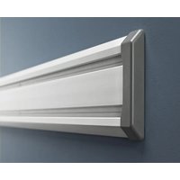
GAACGE4PPM - Garage storage Gladiator - Free user manual and instructions
Find the device manual for free GAACGE4PPM Gladiator in PDF.


| Brand | Gladiator |
| Model | GAACGE4PPM |
| Product Type | Garage Wall Storage System |
| System Components | GearTrack® Tracks and GearWall® Panels |
| Maximum Weight Capacity | Tracks: 75 lb per linear foot (34 kg per 30.48 cm); Panels: 50 lb per square foot (244 kg per m²) |
| Material | Coated Steel |
| Panel Dimensions (Standard) | 1.22 m x 2.44 m (4 ft x 8 ft) |
| Track Lengths | Available in 81.3 cm (32"), 106.7 cm (42"), and 121.9 cm (48") |
| Compatible Accessories | Hooks, bins, baskets, shelves (sold separately) |
| Supported Wall Types | Masonry/concrete, wood studs, drywall over studs |
| Mounting | Screws included (depending on wall type) and construction adhesive recommended |
| Installation Tools Required | Level, drill, stud finder, tape measure, saw (jigsaw or circular saw) |
| Minimum Installation Length Required | Track: length ≥ 60.96 cm (24"); Panel: length ≥ 60.96 cm (24") |
| Track Spacing for Cabinet | 45.7 cm (18") on center |
| Maintenance and Cleaning | Wipe with a damp cloth; do not use abrasive products |
| Safety | Read instructions, do not exceed weight limits, avoid drilling into electrical wiring |
| Warranty | Information at www.GladiatorGW.com or phone (USA: 1 866 342-4089, Canada: 1 800 807-6777) |
| Repairability | Replacement parts sold separately (hooks, tips, trims) |
Frequently Asked Questions - GAACGE4PPM Gladiator
User questions about GAACGE4PPM Gladiator
0 question about this device. Answer the ones you know or ask your own.
Ask a new question about this device
Download the instructions for your Garage storage in PDF format for free! Find your manual GAACGE4PPM - Gladiator and take your electronic device back in hand. On this page are published all the documents necessary for the use of your device. GAACGE4PPM by Gladiator.
USER MANUAL GAACGE4PPM Gladiator
Install the GearTrack® Channels....4
Install the Gearwall® Panels 7
INSTALLATION INSTRUCTION OF HOOKS, BINS AND BASKETS....12
WARRANTY 14
TABLE DES MATIÈRES
SÛRETÉ DES INSTALLATIONS DES PROFILÉS GEARTRACK® ET DES PANNEAUX GEARWALL®....16
INSTRUCTIONS D'INSTALLATION DES PROFILÉS GEARTRACK® ET DES PANNEAUX GEARWALL®....16
Installation des profilés GearTrack 18
www.gladiatorgarageworks.com
www.gladiatorgarageworks.ca
GEARTRACK® CHANNELS AND GEARWALL® PANELS INSTALLATION SAFETY
Your safety and the safety of others are very important.
We have provided many important safety messages in this manual and on your appliance. Always read and obey all safety messages.

This is the safety alert symbol.
This symbol alerts you to potential hazards that can kill or hurt you and others.
All safety messages will follow the safety alert symbol and either the word "DANGER" or "WARNING."
These words mean:
DANGER
You can be killed or seriously injured if you don't immediately follow instructions.
WARNING
You can be killed or seriously injured if you don't follow instructions.
All safety messages will tell you what the potential hazard is, tell you how to reduce the chance of injury, and tell you what can happen if the instructions are not followed.
GEARTRACK® CHANNELS/GEARWALL® PANELS INSTALLATION INSTRUCTIONS
Parts and Tools
■ Remove all parts and fasteners from their packaging, and dispose of/recycle all packaging materials.
■ Gather the required tools and parts before starting installation. Read and follow the instructions provided with any tools listed here.
| PARTS | ||||||
| Parts | GearTrack®Channels GearWall | ®Panels | ||||
| Masonry / Poured Concrete | Bare Wood Studs | Drywall Over Wood Studs 1/2"(1.3 cm), 5/8" (1.6 cm), 3/4" (1.9 cm) | Masonry / Poured Concrete | Bare Wood Studs | Drywall Over Wood Studs 1/2"(1.3 cm), 5/8" (1.6 cm), 3/4" (1.9 cm) | |
| #8 x 11⁄4"(3.08 cm)* | ||||||
| #8 x 2" (5.08 cm) (included)* | ||||||
| 3/16" (4.76 mm) x 13⁄4" (4.45 cm)** | ||||||
| Construction adhesive | ||||||
| 2" (5.08 cm) x 4" (10.16 cm) Wooden studs | ||||||
| 1⁄4" (6.3 mm) x 23⁄4" (6.99 cm)** | ||||||
* Use an all-weather flat-head type deck screw.
** Use a flat-head type masonry screw.
| TOOLS | ||||||
| Tools | GearTrack®Channels GearWall | ®Panels | ||||
| Masonry / Poured Concrete | Bare Wood Studs | Drywall Over Wood Studs 1⁄2"(1.3 cm), 5/8" (1.6 cm), 3⁄4" (1.9 cm) | Masonry / Poured Concrete | Bare Wood Studs | Drywall Over Wood Studs 1⁄2"(1.3 cm), 5/8" (1.6 cm), 3⁄4" (1.9 cm) | |
| Level | ||||||
| Tape Measure | ||||||
| Cordless Drill | ||||||
| 1/8" (3 mm) Drill Bit for Pre-drilling holes | ||||||
| Stud Finder | ||||||
| Ac Finder | ||||||
| Square | ||||||
| Pencil | ||||||
| Jigsaw | ||||||
| Circular Saw | ||||||
| Chalk Line | ||||||
| Line Level | ||||||
| Hammer Drill | ||||||
| Caulk Gun | ||||||
| Chalk Line With Plumb Bob | ||||||
| 3⁄16"(4.7 mm) X 5"(12.7 cm) Masonry Drill Bit | ||||||
| 5/32"(3.9 mm) Masonry Drill Bit | ||||||
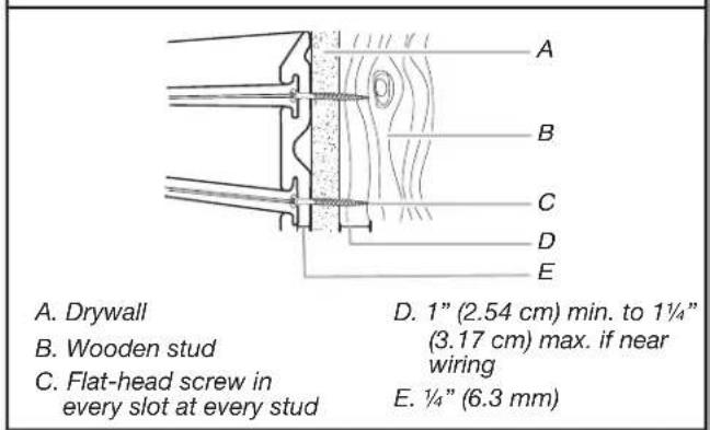
■Screw thread engagement into the wooden stud should be 1" (2.54 cm) minimum. For drywall of a thickness not listed in the chart above, see graphic below.
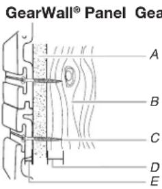
A. Drywall
B. Wooden stud
C. Flat-head screw in every slot at every stud
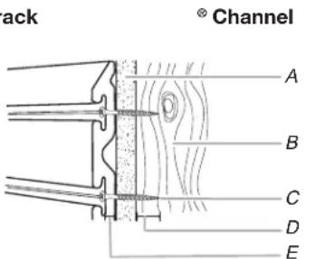
D. 1" (2.54 cm) min. to 1¼" (3.17 cm) max. if near wiring
E. 1/4" (6.3 mm)
IMPORTANT: Compare screw length to electrical wire locations. Be sure the screw will not pierce electrical wiring.
NOTE: Maximum weight limit is 75 lbs per linear ft (30.48 cm) for GearTrack® Channels and 50 lbs per sq ft (2.39 kPa) for GearWall® Panels
Install the GearTrack® Channels
Prepare the Wall
Masonry Block / Poured Concrete Wall
■Before installing GearTrack® to masonry walls, you must waterproof the walls to avoid mildew or foundation damage. Walls that appear dry may actually become damp when enclosed by paneling. Install the channels in accordance with all local codes and ordinances.
Wood Studs and Drywall over Wood Studs
- Locate Studs and Electrical
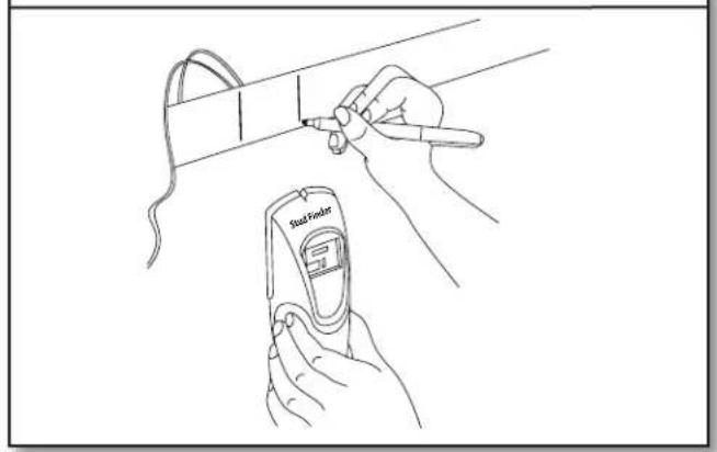
■Use a stud finder to mark the edges of the studs within your planned installation area. Be sure to also mark the locations of electrical wiring.
IMPORTANT: Compare screw length to electrical wiring locations. Be sure the screw will not pierce electrical wiring.
- Cut to Length
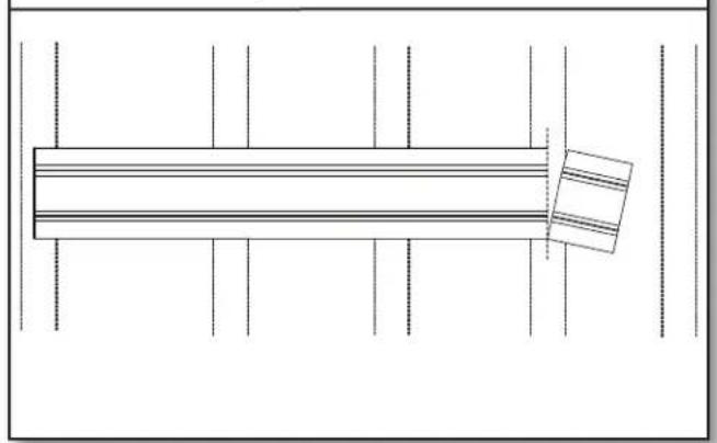
■If necessary, cut the first channel to this length, making sure the cut is square.
NOTE: Channels cut to shorter than 24" (60.96 cm) long should not be used.
- Measure the Channels
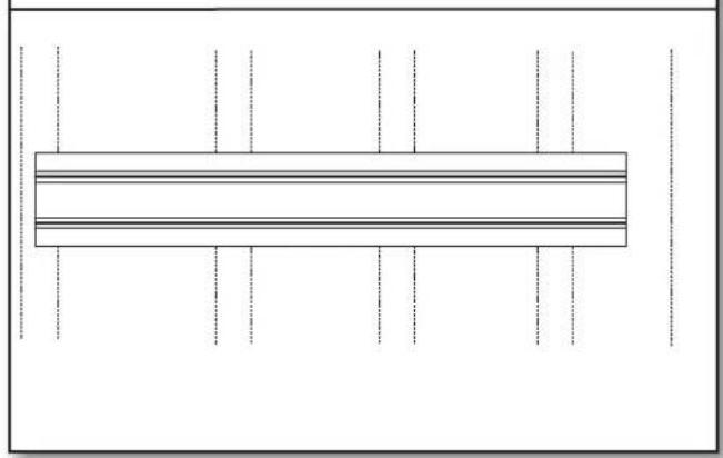
■GearTrack® Channels should be mounted to the wall so that they begin and end at wooden studs. Measure from the center of the stud at the beginning of the desired coverage area to the center of the last wooden stud that is within 32" (81.3 cm), 42" (106.7 cm) or 48" (121.9 cm), depending on the length of your GearTrack® Channel.
Mounting the Channels
- Drive First Screw
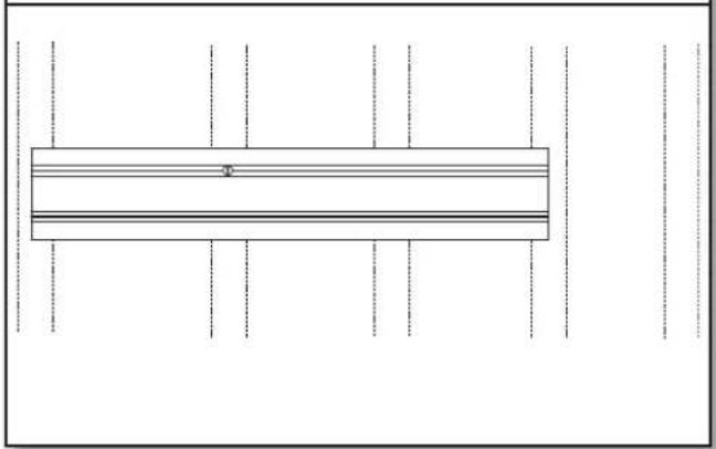
■Holding the channel up in the desired location, drive a screw through the top slot groove and into the center of the stud nearest to the middle of the channel until it is flush with the surface.
NOTE: If installing GearTrack® Channels on masonry block or poured concrete, you may put construction adhesive on the GearTrack® Channel before attaching it to the wall for extra hold.
- Predrill Holes
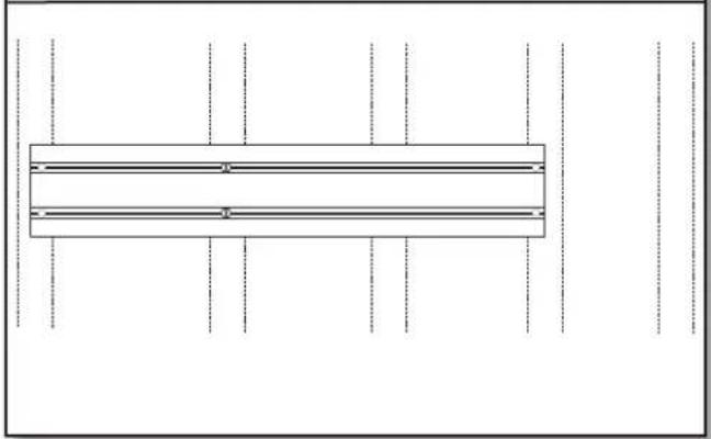
■If splitting occurs, you may find it necessary to predrill and countersink the screw holes near channel ends with a 1/8 " (3 mm) drill bit.
- Inspect Screw Installation
■Make sure all screws are installed and flush with the channel.
- Level the Channel
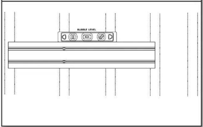
■Check that the GearTrack® Channel is level, and then drive a second screw through the bottom slot groove and into the center of the same stud as in the previous step.
- Drive Remaining Screws
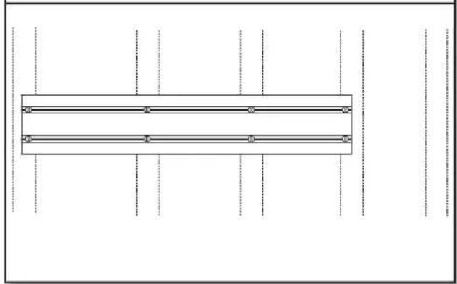
■Drive a screw in every slot at every stud location.
- Repeat for Additional Channels
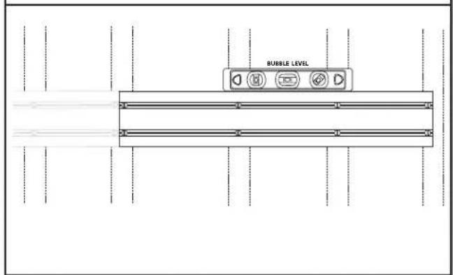
■Repeat this process for the next desired application area.
- Channel Spacing
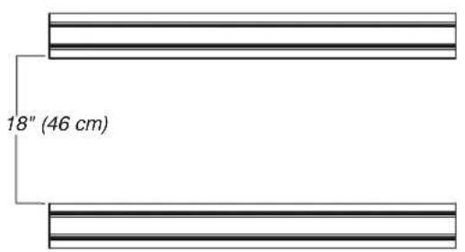
NOTE: If channels are to be used to support accessory hooks and/or small item bins, they may be spaced in any way desired. If channels are being used to support Gladiator® Wall GearBoxes, they must be installed 18" (46 cm) apart.
- Install Ends Caps (sold separately)
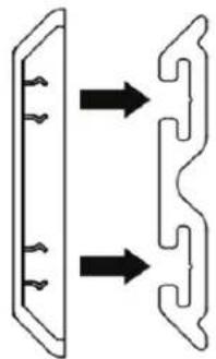
■From the front, snap the end cap onto each end of the run of GearTrack® Channel.
Install the GearWall® Panels
Plan your Installation
- Measure Ceiling Sag
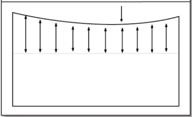
■Snap a level chalk line at a convenient height on the wall(s). Measure from the chalk line to the ceiling and determine the lowest point of the ceiling along the wall.
- Mark Bottom of Wall
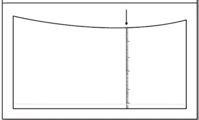
■Starting from the lowest point of the ceiling, measure down to the floor. Round the measurement down to the nearest foot and mark. Snap a level chalk line 1/4 " (6.3 mm) below the mark. Repeat step for remaining walls.
NOTE: For partial wall installation, simply snap a level chalk line at the desired height of the bottom of the wall.
Prepare the Wall
Masonry Block / Poured Concrete Wall
Before you can install the panels on poured concrete or masonry block walls, you must install 2" (5.08 cm) x 4" (10.16 cm) wooden studs to the wall with the 4" (10.16 cm) side against the wall. The wooden studs must be installed over the entire area to be covered by the GearWall® panels. This provides a level surface on which to mount the panels.
- Mount First Stud
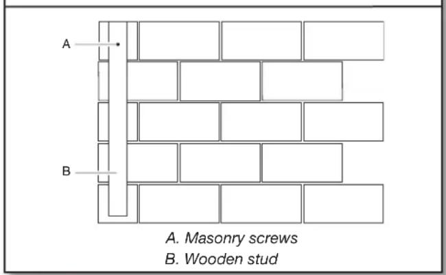
■Install the first stud at the starting edge of the desired coverage area to act as a guide. Drill a hole through the stud and into the wall surface. Follow masonry screw manufacturer's instructions for proper installation. For best results use a hammer drill and masonry bit.
NOTE: For extra hold, you may choose to put construction adhesive on the stud before attaching it to the wall.
- Secure First Stud
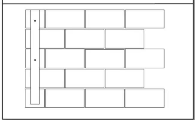
- Secure the stud to the wall by placing 1/4" (6.3 mm) x 23/4" (6.9 cm) masonry screws every 18" (45.72 cm).
3. Measure Location of Remaining Studs
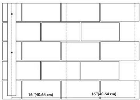
■Use this stud as your guide. Measure 16" (40.64 cm) from the corner and snap a vertical chalk line using a chalk line with a plumb bob. Snap a chalk line every 16" (40.64 cm) from this point.
Wood Studs and Drywall over Wood Studs
1. Locate Studs and Electrical
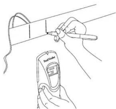
■Use a stud finder to mark the edges of the studs within your planned installation area. Be sure to also mark the locations of electrical wiring.
IMPORTANT: Compare screw length to electrical wiring locations. Be sure the screw will not pierce electrical wiring.
4. Mount Remaining Studs
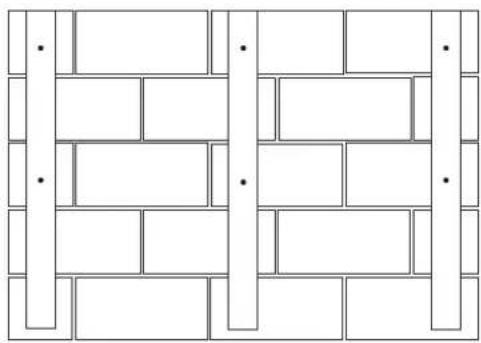
■Align the center of the stud with the chalk line. Attach the remaining studs to the wall as you did in steps 1-2.
Mount the Panels
- Orient the Panel
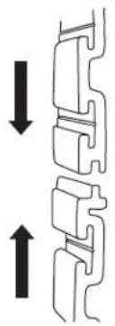
■Panels are installed with the interlock tongue up and the groove down.
- Cut to Length
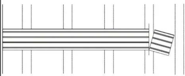
■Cut the first panel to this length, making sure the cut is square. Be sure to also cut around any windows, doors, and outlets.
NOTE: Panels shorter than 24" (60.96 cm) long should not be used.
- Drive First Screw
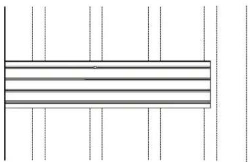
■Holding the panel up in the desired location, drive a screw through the top slot groove and into the stud nearest to the middle of the channel until it is flush with the surface.
- Measure the Panel
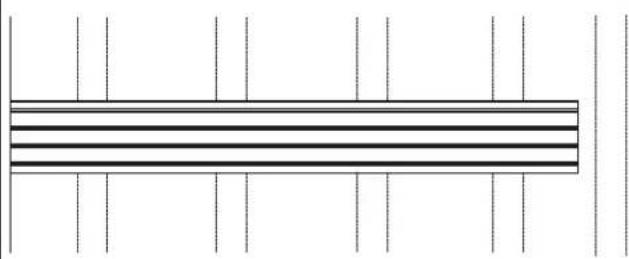
■Measure from the starting edge of the desired coverage area to the center of the last wooden stud that is within 4 ft (1.22 m). Take note of interference with any windows, doors, and outlets.
- Locate the Panel
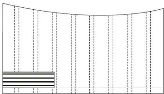
■Place the panel above the horizontal chalk line applied in the "Prepare the Wall" section. Align the panel with both the starting edge and the horizontal chalk line.
NOTE: If installing an optional trim kit, be sure to apply the trim at this time if mounting against an interior corner (see "Trim Options" for details).
- Level the Panel
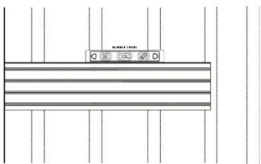
■Check that the panel is level, and then drive a second screw through the bottom slot groove and into the same stud as in the previous step.
- Predrill Holes
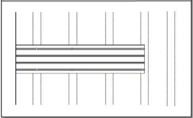
■If splitting occurs, you may find it necessary to predrill and countersink the screw holes near channel ends.
- Drive Remaining Screws
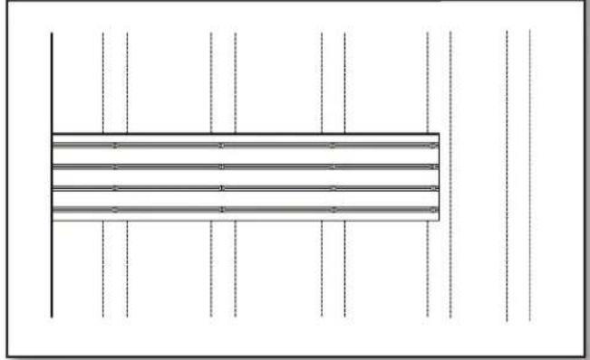
■Drive a screw in every slot at every stud location.
- Repeat Until Row Complete
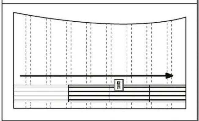
■Repeat steps 1-4 with additional panels until you reach the opposite edge of the desired coverage area.
NOTE: If installing an optional trim kit, be sure to apply the trim around any windows, doors, and outlets you encounter along the way, as well as to the final piece of the row if mounting against an interior corner (see "Trim Options" for details).
- Repeat Until Desired Coverage
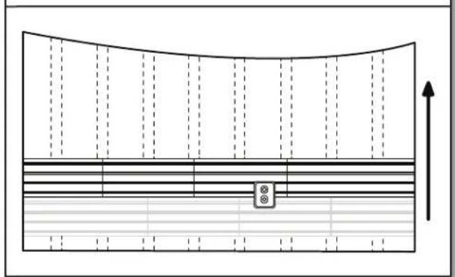
■Repeat step 5, installing each following row of wall panels until the wall is finished. If the wall is wider than the 4 ft (1.22 m) panel, you will need to stagger the vertical panel joints in each row with the seams at the wooden studs, as shown.
NOTE: The final row of panels can be rip cut lengthwise to fit the required height.
Trim Options
■ You may choose to apply trim to any exposed corners or edges. Below are some recommended configurations:
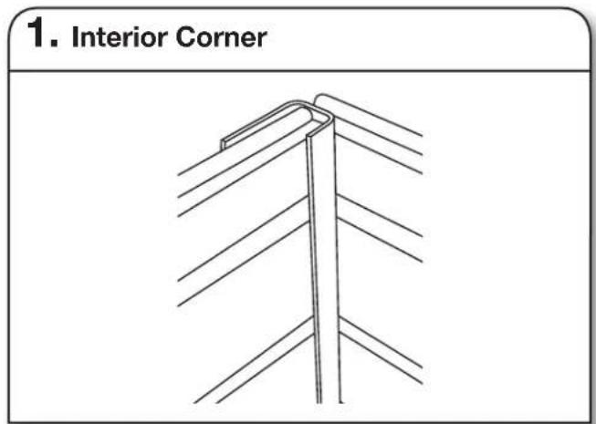
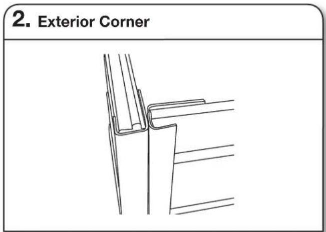
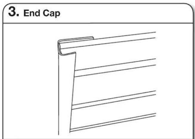
NOTE: The current trim options do not apply to masonry block or poured concrete wall installation.
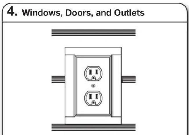
- Trim may also be applied around windows, doors, and outlets. Be sure to notch the trim as shown to ensure a snug fit:
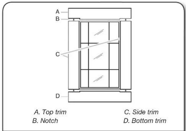
INSTALLATION INSTRUCTION OF HOOKS, BINS AND BASKETS
| Parts Maximum Weight Limit | |
| Claw Hook, Dual Hook, Big Hook, Utility Hook 50 lbs | (22.7 kg) |
| Horizontal Bike Hook 25 lbs (11.3 kg) for each hook and 50 lbs (22.7 kg) for the pair | |
| Deep Hook, Wide Hook, Vertical Bike Hook 30 lbs (13.6) | |
| Tool Hook, Cradle Hook, Twin Hook, S Hook, Scoop Hook | 25 lbs (11.3 kg) |
| Fishing Pole Hook 10 lbs (4.5 kg) for each hook and 20 lbs (9.1 kg) for the pair | |
| J & L Hook, Loop Hook 5 lbs (2.2 kg) | |
| Storage Bin Holder 25 lbs (11.3 kg) for each hook and 50 lbs (22.7 kg) for the pair | |
| 24” (60.96 cm) Mesh Basket 35 lbs (15.9 kg) | |
| 18” (45.7 cm) Wire Basket 35 lbs (15.9 kg) | |
| Caddy Bag 25 lbs (11.3 kg) | |
| Small Item Bin 10 lbs (4.5 kg) | |
IMPORTANT : Intended to be installed on Gladiator® Garageworks GearWall® panels or GearTrack® channels.
NOTE : Be sure the Gladiator® GearWall® panel or GearTrack® channel is installed with mounting screws in every slot and at every stud location with a maximum of 24" (60.96 cm) horizontally between screws.
 Big Hook Big Hook | 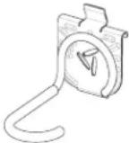 Vertical Bike Hook Vertical Bike Hook | 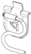 S Hook S Hook | 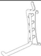 L Hook L Hook |
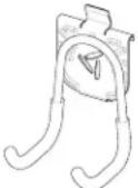 Utility Hook Utility Hook | 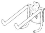 Tool Hook Tool Hook | 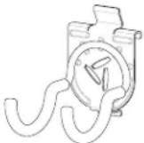 Scoop Hook Scoop Hook | 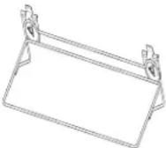 Mesh Basket Mesh Basket |
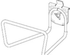 Deep Hook Deep Hook | 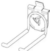 Twin Hook Twin Hook | 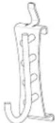 J Hook J Hook | 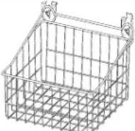 Wire Basket Wire Basket |
Hooks Installation to GearTrack® Channels/GearWall® Panels
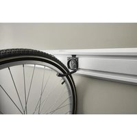
Install the Claw Hook Advanced Bike Storage v3.0
Claw Hook Advanced Bike Storage
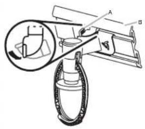
A. Lever lock
B. GearTrack® channel
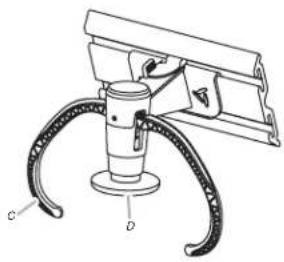
C. Hook arm
D. Plunger
Install the Fishing Pole Hook
Fishing Pole Hook (Vertical)
IMPORTANT :
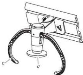
■The Gladiator Claw™ Advanced Bike Storage v3.0 hook holds either wheel of a bike.
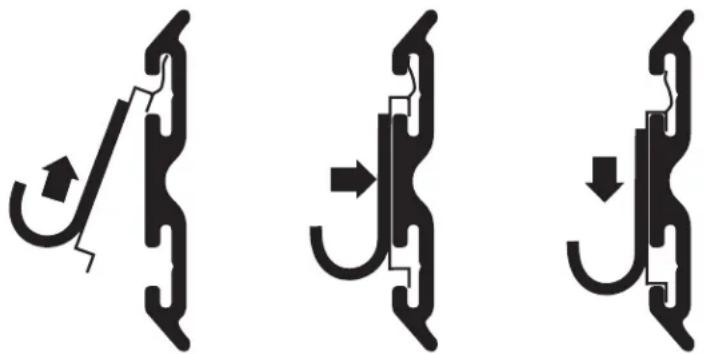
- Determine where you want to hang the bike. Engage the storage hook mounting bracket into the wall slots by lifting up, pushing toward the wall and lowering the bracket rims into the slots.
- Inspect the bike storage hook from the side to make sure the mounting bracket rims are fully engaged in the slots.
- Turn the lever lock counterclockwise to lock the storage hook to the GearWall® panel or GearTrack® channel. Make sure the lever lock is in the fully locked position, as shown.
- Press the plunger until the hook arms are in the open position.
- Lift the bike up and press the bike tire against the plunger. The hook arms will close around the wheel. Make sure both arms are completely closed around the wheel.
- Remove the bike by lifting the bike up and pressing the tire against the plunger. The hook arms will open to release the bike wheel.
Fishing Pole Hook (Horizontal)

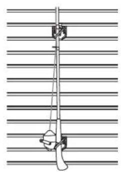
■Designed to be used as a pair, the set of four fishing pole holders will support two fishing poles mounted either vertically or horizontally, as shown.
- Install the fishing pole holders into the slots in the GearWall® panel or GearTrack® channel so that distance between the holders is one half the length of the fishing pole.
NOTE : Engage the bracket rims into the slots by lifting up, pushing toward the wall and lowering the rims into the slots.
- Inspect the bracket from the side to ensure the rims are fully engaged in the slots as shown.
- Set the fishing pole into the holders.
Install the Horizontal Bike Hook
Horizontal Bike Hook
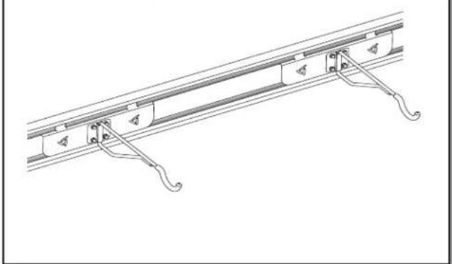
■When not in use, bike hook may be rotated to the side so it lies flat against the bracket.
- Engage the bracket rims on the horizontal bike hook into the slots in the GearWall® panel or GearTrack® channel by lifting up, pushing toward the wall and lowering the rims into the slots.
- Inspect the bracket from the side to ensure the rims are fully engaged in the slots as shown.
Install the Storage Bin Holder
Storage Bin Holder
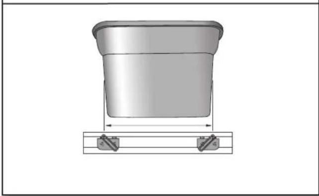
■Designed to be used as a pair, the bin holders will support one storage bin up to a maximum 18 gallon size.
- Measure the length of the storage bin 4" (10.2 cm) to 5" (12.7 cm) from the bottom.
- Install the storage bin holders into the slots in the GearWall ® panel or GearTrack ® channel so that distance between the top of the holders is the same as the length of the storage bin.
NOTE : Engage the bracket rims into the slots by lifting up, pushing toward the wall and lowering the rims into the slots. - Inspect the bracket from the side to ensure the rims are fully engaged in the slots as shown.
- Set the storage bin into the bin holders so that the bottom and sides are supported by the storage bin holders.
WARRANTY
For warranty information:
In U.S.A. call 1-866-342-4089 or visit our website at
www.GladiatorGW.com
In Canada call 1-800-807-6777 or visit our website at
www.gladiatorgarageworks.ca
There are many benefits for registering the product. Find out more and register the product online at www.gladiatorgarageworks.com.
NOTES
SÛRETÉ DES INSTALLATIONS DES PROFILÉS GEARTRACK® ET DES PANNEAUX GEARWALL®
IMPORTANT :
www.gladiatorgarageworks.ca
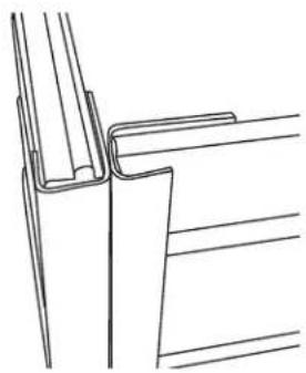
- Esquina exterior
A. Traba de palanca
B. Canal GearTrack®
www.gladiatorgarageworks.ca
www.gladiatorgarageworks.com.
NOTAS
6 /TM ©2017 Gladiator. All rights reserved. Used under license in Canada.
- TABLE DES MATIÈRES
- GEARTRACK® CHANNELS AND GEARWALL® PANELS INSTALLATION SAFETY
- YOUR SAFETY AND THE SAFETY OF OTHERS ARE VERY IMPORTANT
- DANGER
- WARNING
- GEARTRACK® CHANNELS/GEARWALL® PANELS INSTALLATION INSTRUCTIONS
- PARTS AND TOOLS
- INSTALL THE GEARTRACK® CHANNELS
- PREPARE THE WALL
- MASONRY BLOCK / POURED CONCRETE WALL
- WOOD STUDS AND DRYWALL OVER WOOD STUDS
- MOUNTING THE CHANNELS
- INSTALL THE GEARWALL® PANELS
- PLAN YOUR INSTALLATION
- MEASURE LOCATION OF REMAINING STUDS
- LOCATE STUDS AND ELECTRICAL
- MOUNT REMAINING STUDS
- MOUNT THE PANELS
- TRIM OPTIONS
- INSTALLATION INSTRUCTION OF HOOKS, BINS AND BASKETS
- INSTALL THE CLAW HOOK ADVANCED BIKE STORAGE V3.0
- INSTALL THE FISHING POLE HOOK
- IMPORTANT
- INSTALL THE HORIZONTAL BIKE HOOK
- INSTALL THE STORAGE BIN HOLDER
- WARRANTY
- NOTES
- SÛRETÉ DES INSTALLATIONS DES PROFILÉS GEARTRACK® ET DES PANNEAUX GEARWALL®
- NOTAS
Brand : Gladiator
Model : GAACGE4PPM
Category : Garage storage