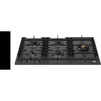
P905LMODNE - Cooker BERTAZZONI - Free user manual and instructions
Find the device manual for free P905LMODNE BERTAZZONI in PDF.


| Product type | Built-in gas hob |
| Brand | Bertazzoni |
| Model | P905LMODNE |
| Dimensions (W x D x H) | 89.3 x 52.5 x 4.4 cm |
| Weight | Approximately 15 kg |
| Gas supply | Natural gas (G20/G25) or LPG (G30/G31) – convertible |
| Electrical supply | 220-240 V, 50/60 Hz |
| Number of burners | 5 (1 auxiliary, 2 semi-rapid, 1 rapid, 1 Dual/crown) |
| Burner power | Auxiliary: 1.0 kW, Semi-rapid: 1.75 kW, Rapid: 3.0 kW, Crown: 4.0 kW, Dual Wok: 5.0 kW |
| Ignition type | Built-in automatic ignition (piezo) and manual ignition |
| Safety | Thermocouple on each burner (automatic gas shut-off) |
| Worktop material | Tempered glass |
| Grilles | Enameled cast iron, with wok supports |
| Cleaning | Wash crowns and grilles with warm soapy water – do not use abrasives |
| Included accessories | Wok adapter and reduction for coffee maker |
| Installation | Built-in (cutout required), above an oven or drawer with double bottom |
| Warranty | 2 years (parts and labor) |
Frequently Asked Questions - P905LMODNE BERTAZZONI
User questions about P905LMODNE BERTAZZONI
0 question about this device. Answer the ones you know or ask your own.
Ask a new question about this device
Download the instructions for your Cooker in PDF format for free! Find your manual P905LMODNE - BERTAZZONI and take your electronic device back in hand. On this page are published all the documents necessary for the use of your device. P905LMODNE by BERTAZZONI.
USER MANUAL P905LMODNE BERTAZZONI
INSTALLATION AND USER MANUAL
BUILT-IN GAS HOBS
MODEL P93V (METAL)
MODEL P94GV (GLASS)
INSTRUCTIONS D'INSTALLATION ET D'UTILISATION
PLAQUES DE CUISSON ENCASTRABLES AU GAZ
TYPE P93V (MÉTAL)
TYPE P94GV (VERRE)
ACCENSIONE MANUALE 15
ACCESSORI 15
PULIZIA DELL'APPARECCHIO 15
MALFUNZIONAMENTO 16

DALLA SCRIVANIA DEL PRESIDENTE
Gentile Cliente,
MANUALE TECNICO PER L'INSTALLATORE
natural_image
Technical line drawing of a mechanical assembly with no visible text or symbols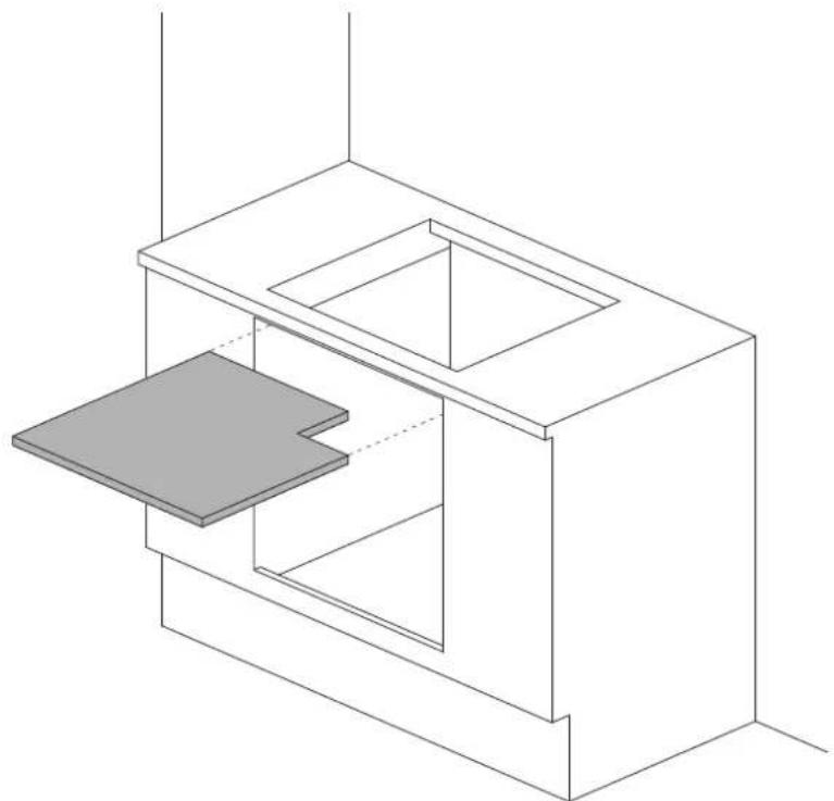
natural_image
Isometric line drawing of a 3D architectural or mechanical structure with two rectangular compartments and a gray panel on the left (no text or symbols)natural_image
Technical line drawing of a mechanical assembly with no visible text or symbolsnatural_image
Diagram of a screwdriver adjusting a mechanical component with a rotating arrow (no text or symbols)natural_image
Isometric line drawing of a room interior with a central cabinet and directional arrow (no text or symbols)natural_image
Isometric line drawing of a kitchen appliance with a chimney and base (no text or symbols)Figura A
natural_image
Isometric line drawing of a room interior with a cabinet and vent, showing no text or symbolsFigura B
ALLACCIAMENTO DELL'APPARECCHIO ALLA RETE GAS
natural_image
Technical line drawing of a mechanical assembly with no visible text or symbolsPRECAUZIONI PER L'UTILIZZO DEL PRODOT- TO CON GAS GPL:

natural_image
Technical line drawing of a mechanical assembly with a central tool and circular base (no text or symbols)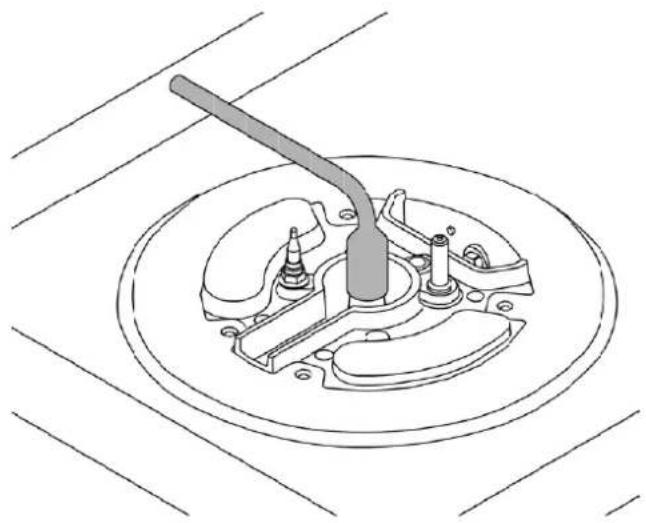
natural_image
Technical line drawing of a mechanical switch assembly (no text or symbols)
natural_image
Simple line drawing of a cable or cable with labeled points L and N, and a small object near the base (no text or symbols beyond labels)natural_image
Simple diagram with a circle, star, droplet, and droplet symbols (no text or labels)UTILIZZO BRUCIATORE DUAL (dove previsto)
natural_image
Simple circular diagram with a vertical line, three water droplets below, and a black dot above (no text or symbols)INSTALLATION AND USER MANUAL
BUILT-IN GAS HOBS
MODEL P93V (METAL)
MODEL P94GV (GLASS)

CONTENTS
INTRODUCTION AND WARNINGS 4
MANUFACTURER LIABILITY 4
ENVIRONMENTAL PROTECTION 4
GENERAL SAFETY INSTRUCTIONS 5
USAGE INSTRUCTIONS 5
APPLIANCE DATA PLATE 5
PLASTIC PACKAGING 5

TECHNICAL INSTALLATION INSTRUCTIONS 6
HOB INSTALLATION 6
IMPORTANT INFORMATION 6
INSTALLING THE HOB ABOVE AN OVEN 7
INSTALLING THE HOB ABOVE A CUPBOARD OR DRAWERS 7
HOB FASTENING 8
ROOM VENTILATION 8
LOCATION AND VENTILATION 9
CONNECTING THE APPLIANCE TO THE GAS SUPPLY 9
PRECAUTIONS WHEN USING THE PRODUCT WITH LPG (BUTANE/PROPANE) 10
GAS CONVERSION 11
ELECTRICAL CONNECTION 12
MAINTENANCE 12
REPLACING COMPONENTS 12
HOB DESCRIPTION 13
USING THE APPLIANCE 14
BURNERS AND GRATES 14
USING THE BURNERS 14
SAFETY SYSTEM 15
MANUAL IGNITION 15
ACCESSORIES 15
CLEANING THE APPLIANCE 15
TROUBLESHOOTING 16
FROM THE DESK OF OUR PRESIDENT

Dear new owner of a Bertazzoni appliance,
I want to thank you for choosing one of our beautiful products for your home.
My family started manufacturing kitchen appliances in Italy in 1882, building a reputation for quality of engineering and passion for good food.
Today, our products stand out because of their unique blend of authentic Italian design and superior appliance technology. It is our mission to make products that function perfectly and bring joy to their owners.
By making beautiful products we respond to our customers' fl air for good design. By making them versatile and easy-to-use, cooking with Bertazzoni becomes a real pleasure.
This manual will help you learn to use and care for your Bertazzoni appliance in the safest and most effective way, so that it can give you the highest satisfaction for years to come.
Enjoy!
Paolo Bertazzoni
P r e s i d e n t
Peso Sectorzoni
INTRODUCTION
READ THESE INSTRUCTIONS CAREFULLY BEFORE INSTALLING AND USING THE APPLIANCE.
These instructions are valid only for the countries whose identifying symbols are shown on the appliance label.
The manufacturer shall not be held liable for property damage or personal injury resulting from incorrect installation or improper use of the appliance.
The manufacturer shall also not be held liable for any imprecisions due to printing or transcription errors in this booklet.
The appearance of the figures included herein is only for guidance.
The manufacturer reserves the right to make modifications to its products when it considers this necessary or beneficial, however the essential safety and performance characters shall not be affected.
THIS APPLIANCE IS DESIGNED FOR NON-PROFESSIONAL, DOMESTIC USE.
This user manual is an integral part of the appliance and must therefore be kept in its entirety in a place accessible to the user for the entire lifetime of the appliance.
Read this manual before using the appliance.
MANUFACTURER LIABILITY
The manufacturer shall bear no liability for property damage or personal injury due to:
• Use of the appliance other than that specified
- Failure to comply with the instructions in the user manual
- Tampering with/unauthorised modifications to any part of the appliance
• The use of non-original spare parts.
- This appliance is intended for cooking food in the home environment. Any other use shall be considered improper.
- The appliance is not designed to operate with external timers or with remote-control systems.
WARNING: The c€ marking on this product is a declaration, under the manufacturer's full responsibility, that the product complies with all European health, safety and environmental requirements laid out in the legislation covering this product type.
ENVIRONMENTAL PROTECTION
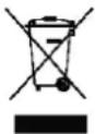
Please think of the environment when disposing of the packaging.
This appliance is marked in accordance with European Community Directive 2012/19/EU on waste electrical and electronic equipment (WEEE).
This directive defines the standards for the collection and recycling of waste electrical and electronic equipment applicable throughout the European Union.
The packaging of this appliance is composed of the elements strictly necessary to ensure sufficient protection during transport. The packaging materials are completely recyclable, thus reducing their environmental impact. Please help to protect the environment by taking the following tips into consideration:
- Sort the packaging materials for recycling
- Render the old appliance unusable before taking it to the collection facility Ask the competent local authorities for details of the nearest recycling centre you can take the old appliance to.
- Do not dispose of used oil down the drain. Keep it in a closed container and take it to a recycling centre; if this is not possible, dispose of it in mixed waste (in this manner it will be disposed of at a monitored facility – although this is not the best solution, it at least prevents contamination of the sewage/water systems).
INTRODUCTION
GENERAL SAFETY INSTRUCTIONS
- During use, the appliance and its accessible parts become very hot.
- Never touch the heating elements during use.
- Keep children under the age of eight at a safe distance unless they are constantly supervised.
• Children must not play with the appliance.
- This appliance may only be used by children over the age of eight, and by people with reduced physical, sensory or mental capacity, or lacking in experience in the use of electrical appliances, provided that they are supervised or instructed by adults who are responsible for their safety.
- Never rest metal objects on the appliance during use, as these could become red hot.
- Switch off the appliance after use.
- Never try to put out a fi re or fl ames with water: Turn off the appliance and smother the fl ames with a fi re blanket or other appropriate cover.
- Cleaning and maintenance must not be carried out by children without adequate supervision.
- Ensure that hot surfaces are allowed to cool before proceeding to clean the appliance.
- Have installation and servicing carried out by qualified personnel in compliance with applicable standards and legislation. Do not try to repair the appliance yourself or without the assistance of a qualified technician.
- Do not modify this appliance.
- Do not insert anything in the slots.
- Do not obstruct ventilation openings and heat dispersal slots.
- If the power supply cable is damaged, contact technical support immediately and they will arrange for it to be replaced.
- Do not use abrasive or corrosive detergents (e.g. scouring powders, stain removers and metallic sponges) on glass parts.
- Do not sit on the appliance.
- Do not use steam jets to clean the appliance.
- Never leave objects on the cooking surface.
- Do not use the appliance as a space heater for any reason.
- In the event of breakage or cracking of the glass, shut off all burners immediately and isolate the hob's gas and electricity supplies. Contact technical support.
- Sudden and extreme changes in temperature can cause the glass to break – never pour cold liquids onto the hob.
- Damaged or unsuitably sized cookware which overhangs the edges of the hob or is poorly positioned can cause serious injury.
- Using the hob generates heat, moisture and combustion products – keep the area well ventilated during operation.
INSTRUCTIONS FOR USE
- Use flat-based cookware.
- Position pans before lighting the burners.
- Never leave the hob when cooking foods with oil and grease, as they can flash over and ignite easily.
- Do not use aerosols in the vicinity of this appliance while it is in use.
- Adjust the flame so that it does not protrude beyond the edge of the pan base, as this could damage the handles.
- Do not place pans directly on the burners.
- Ensure that the pan is centred over the burner.
APPLIANCE DATA PLATE
The data plate bears the technical data, serial number and brand name of the appliance. The appliance data plate is located on the lower casing, and must not be removed at any time. A copy is provided in this manual for reference.
PLASTIC PACKAGING
Danger of suff ocation
- Do not leave the packaging or any part thereof unattended.
- Do not let children play with the plastic bags.
TECHNICAL INSTALLATION INSTRUCTIONS
The installation, adjustments, transformations and maintenance listed in this section must only be performed by qualified technicians (in accordance with applicable legislation). Incorrect installation can cause property damage and injury to people or pets; the manufacturer shall not be held liable in this event. The appliance's automatic regulation or safety devices may only be modified by the manufacturer or a duly authorised supplier during the appliance's lifetime.
Ensure all necessary PPE is used when carrying out the installation
INSTALLING THE HOB
Ensure that the hob is fully present and undamaged after removing all loose parts from their inner and outer packaging. In the event of any uncertainty, do not use the appliance and contact technical support.
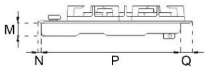
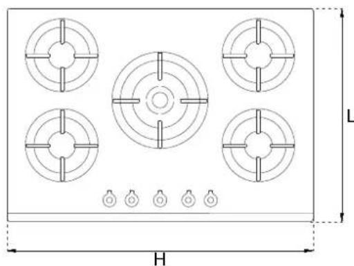
Make a cut-out in the worktop (see figure) in accordance with the appliance dimensions given in the table.
IMPORTANT INFORMATION
The hob may be installed between kitchen cabinets or between a cabinet and a (masonry) wall. The rear wall and surrounding surfaces must be able to withstand temperatures of up to 90°C. To prevent peeling of the melamine laminate typically used on kitchen carcases, the glue bonding it must be able to withstand temperatures of at least 150°C. Installation of the appliance must be performed in accordance with the provisions of applicable legislation.
This domestic appliance is not connected to an extraction device for combustion products. It must therefore be connected in accordance with the above-mentioned installation rules. Particular attention must be paid to room ventilation requirements.
The worktop must be able to withstand a maximum temperature of 90^ C ( 120^ C for the 75cm version)
| A (cm) | B(cm) | |
| 60cm hob | 56 | 48 |
| 75cm hob | 56 | 48 |
| 90cm hob | 85 | 48 |
| H(cm) | L(cm) |
| 60,5 | 52,5 |
| 75,5 | 52,5 |
| 89,3 | 52,5 |
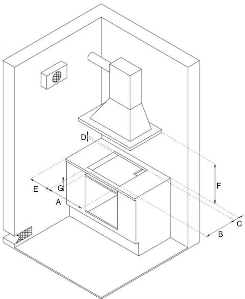
| C min (cm) | 8,5 |
| D min (cm) | 3 |
| E min (cm) | 18 |
| F min (cm) | 70 |
| G min (cm) | 8,5 |
| M (cm) | 4,4 |
| N (cm) | 1,1 |
| P (cm) | 47,4 |
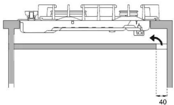
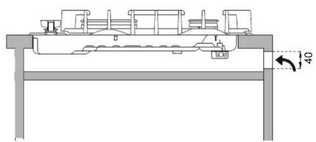
| Q (cm) | 4 |
natural_image
Technical diagram of a gas stove with five circular vented fans and a central hub, shown with dimension labels H and L (no text or symbols on the diagram itself)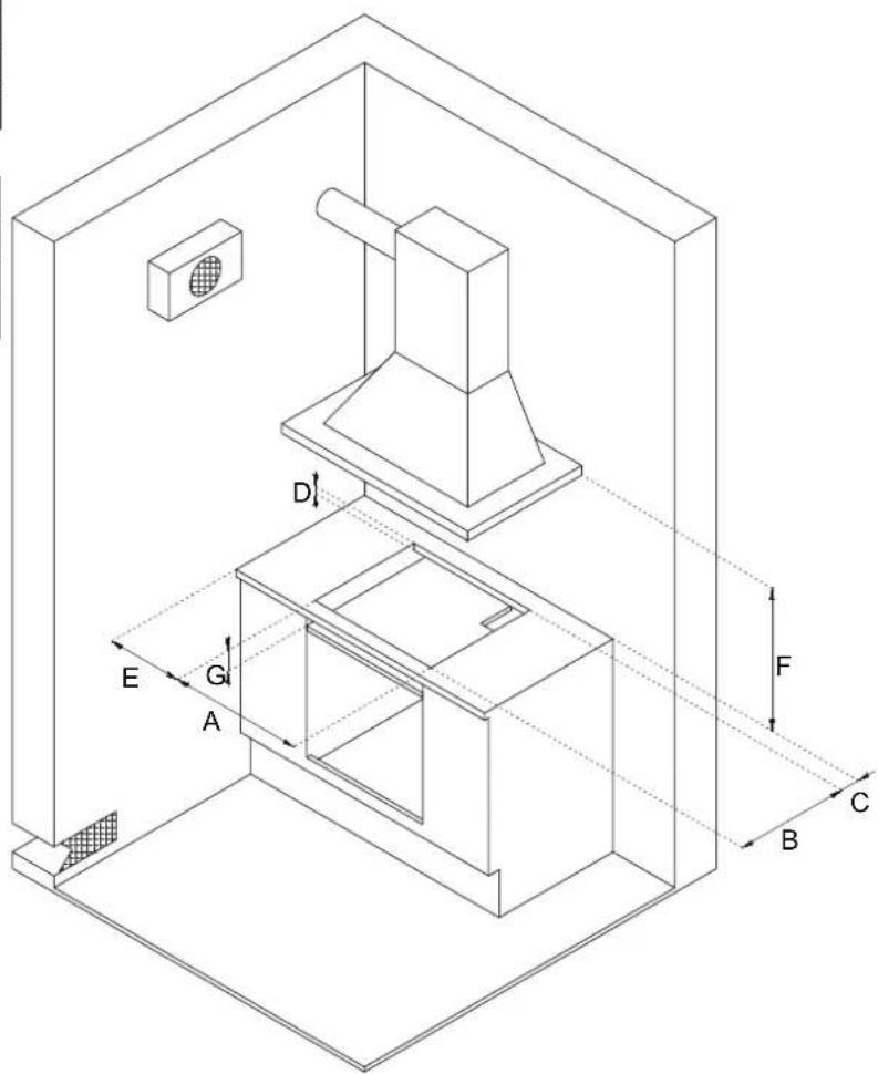
TECHNICAL INSTALLATION INSTRUCTIONS
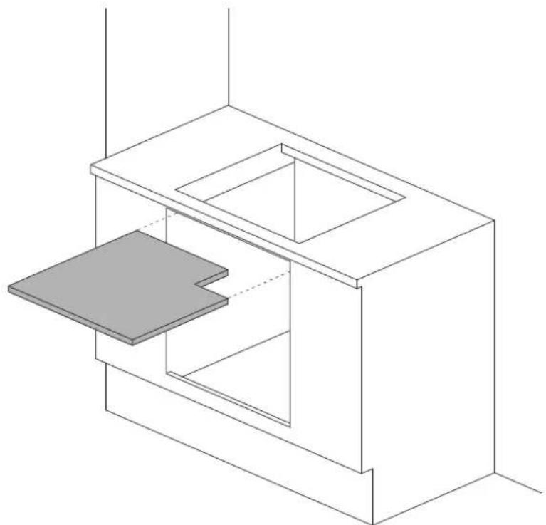
INSTALLING THE HOB ABOVE AN OVEN
The clearance between the hob and the kitchen furniture or other installed appliances must be enough to ensure sufficient ventilation and air discharge.
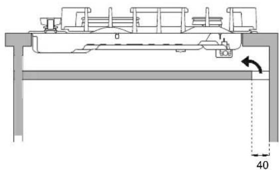
If installed above an oven, space must be left between the bottom of the hob and the top of the product installed below to allow for ventilation of the entire compartment (see figure).
The oven must be equipped with a cooling device. The manufacturer shall bear no liability in the event of the hob being installed in combination with an oven from another manufacturer.
INSTALLING THE HOB ABOVE A CUPBOARD OR DRAWERS
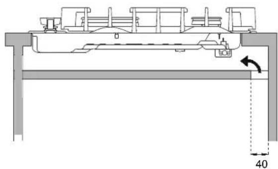
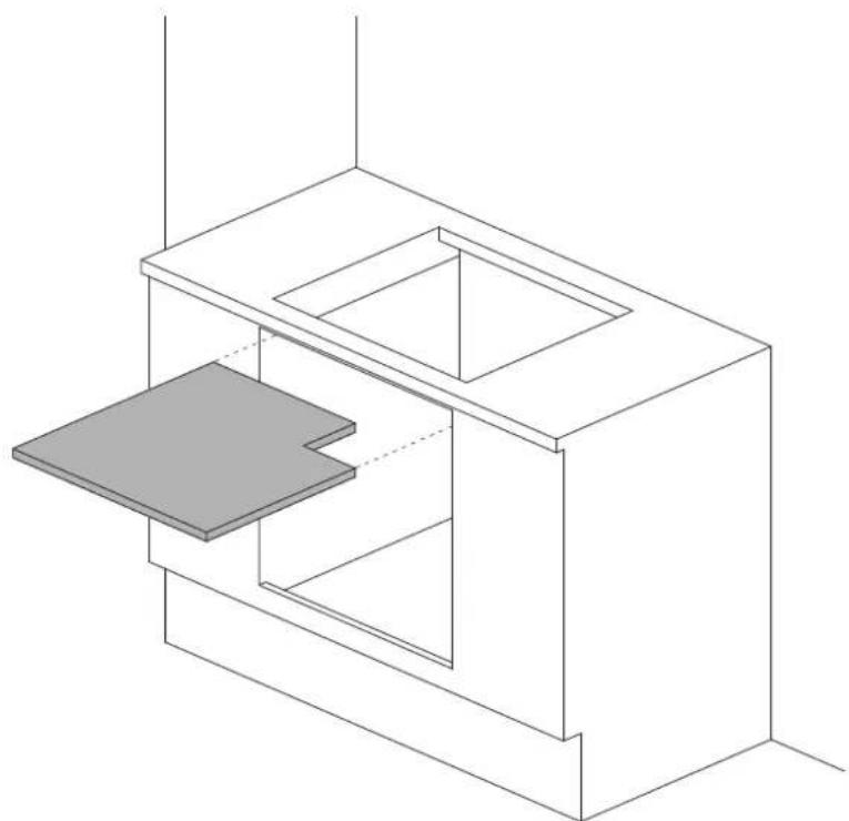
The clearance between the hob and the kitchen units must be enough to ensure sufficient ventilation and air discharge. If there are other units/furniture (side walls, drawers, etc.), dishwashers or fridges under the hob, a double-layer wooden base must be installed at least 20 mm from the bottom of the hob to avoid any accidental contact. It must only be possible to remove the double-layer base using special tools.
natural_image
Technical line drawing of a mechanical assembly with no visible text or symbols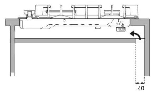
natural_image
Technical line drawing of a mechanical assembly with no visible text or symbols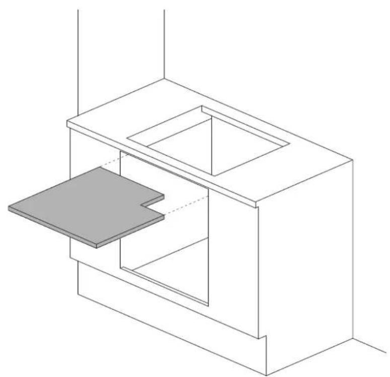
natural_image
Isometric line drawing of a modular building interior with a central platform and two rectangular compartments (no text or symbols)
HOB FASTENING
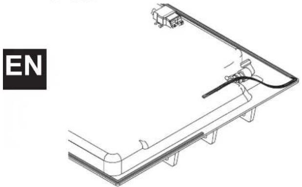
In order to prevent accidental water ingress into the unit below, the appliance is fitted with a special gasket.
1) Lay the sealing gasket out along the lower edge of the built-in hob after cleaning the mating surface.
natural_image
Technical line drawing of a mechanical assembly with no visible text or symbols2) Place the hob into the worktop cut-out.
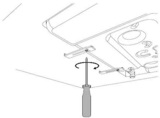
3) To fasten the hob to the worktop, use a screwdriver to install the four plates using the corresponding screw in the bottom of the hob.
natural_image
Technical line drawing of a screwdriver adjusting a mechanical component (no text or symbols)ROOM VENTILATION
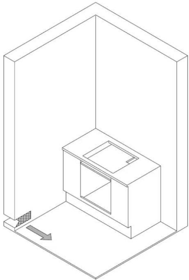
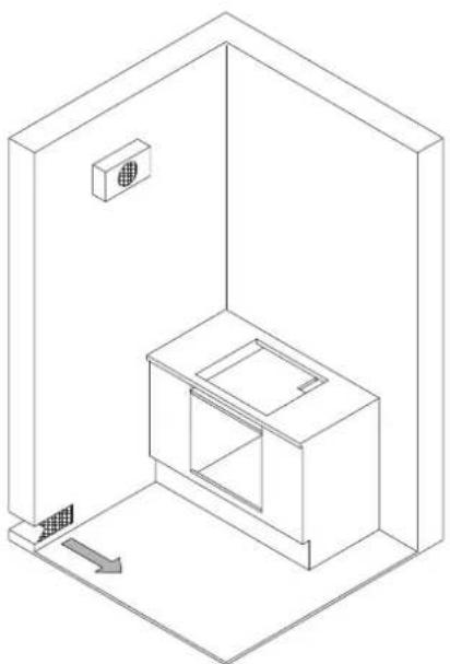
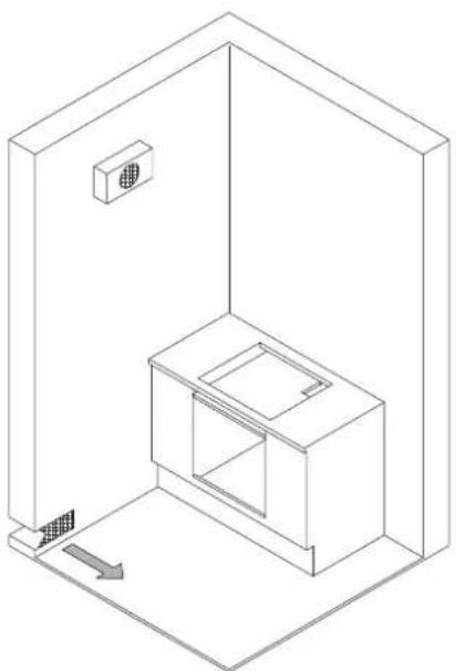
In order to allow for correct appliance operation, the room in which it is installed must have continuous ventilation. The volume of the room must be no less than 25 m^3 , and the quantity of air required must be based on regular combustion of the gas and the room ventilation. The natural air flow must occur through permanent openings in the wall of the room requiring ventilation; these openings must lead directly outdoors, and must have a minimum area of 100 cm^2 .
Indirect ventilation via air taken from rooms adjoining the one to be ventilated is also permitted, as long as all applicable legislation is satisfi ed.
natural_image
Isometric line drawing of a room interior with a cabinet and door, no text or symbols presentLOCATION AND VENTILATION
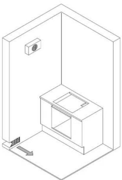
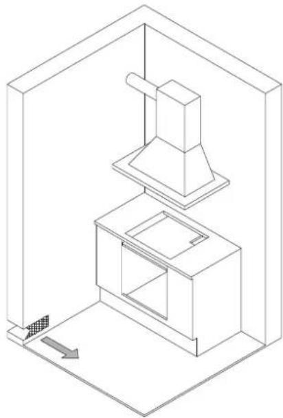
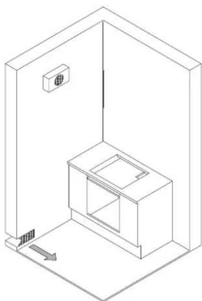
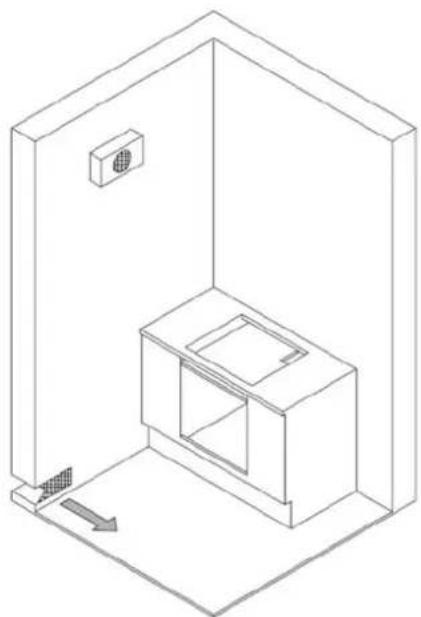
Gas cooking appliances must always have the corresponding combustion products extracted via cooker hoods connected to a fl ue or directly to the outside (see Figure A). If it is not possible to install a cooker hood, the use of an extractor fan installed in a window or ducted directly outside is permissible; this must be connected so as to come on when the appliance is operational (see Figure B), and all ventilation requirements laid out in applicable legislation must be met.
natural_image
Isometric line drawing of a kitchen furnace and stove inside a room (no text or symbols)Figure A
natural_image
Isometric line drawing of a room interior with a cabinet and wall-mounted fixture (no text or symbols)Figure B
CONNECTING THE APPLIANCE TO THE GAS SUPPLY
Before connecting the appliance to the gas supply, check that the data on the product identification label is compatible with the gas supply specifications.
When the gas is supplied from the mains, the appliance must be connected to the gas supply with rigid copper tube or via a steel hose, in accordance with applicable legislation.
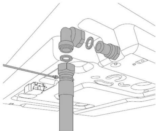
When the gas is supplied from a cylinder, via a compliant pressure regulator with continuous-wall stainless-steel hose, it is advisable to install a special after-market adapter on the hose to facilitate connection with the hose barb of the pressure regulator installed on the cylinder.
The hose must not pass through compartments which may be filled, and must not come into contact with moving components such as drawers. On completing installation, check for any leaks with a soapy solution, never with a flame.
WARNING: Remember that the appliance's gas inlet is a male 1/2" BSPP fi tting to ISO 228-1.
natural_image
Technical line drawing of a mechanical assembly with a tool inserted into a component (no text or symbols visible)
PRECAUTIONS WHEN USING THE PRODUCT WITH LPG (BUTANE/PROPANE)
The gas taps installed on the hob must operate with liquefi ed gas of controlled quality, supplied at the correct nominal pressure.
This pressure must be guaranteed by a certified dedicated pressure regulator (not supplied with the product).
The use of gas from uncertified refi lls and/or improper use of LPG cylinders, as well as the corresponding regulator, can invalidate the product warranty.
In particular, you must avoid all situations where the gas could be polluted with residues and impurities which, when they enter the gas circuit, could
irreparably damage the control components such as the taps and thermostats.
We therefore recommend:
- Using only LPG cylinders from official resellers authorised by the various manufacturers
- Using the cylinders until they are empty but without tilting or overturning them
- Regularly cleaning the filter at the inlet to the pressure regulator
Regulating the appliance for various gas types
Category appliance II 2H3+
| Burner Gas type | Pressure N | Nozzle diameter | Nominal flow rate | Flow rate Reduced | Bypass diameter | |||||
| mbar | 1/100mm | g/h | l/h | kW | kcal/h | kW | kcal/h | 1/100mm | ||
| Auxiliary | Natural gas G20 | 20 | 77 | - | 95 | 1.00 | 860 | 0.3 | 258 | 27 reg |
| Butane G30 | 30 | 50 | 73 | - | 1.00 | 860 | 0.3 | 258 | 27 | |
| Propane G31 | 37 | 50 | 71 | - | 1.00 | 860 | 0.3 | 258 | 27 | |
| Semi-rapid | Natural gas G20 | 20 | 101 | - | 167 | 1.75 | 1505 | 0.44 | 378 | 31 reg |
| Butane G30 | 30 | 66 | 127 | - | 1.75 | 1505 | 0.44 | 378 | 31 | |
| Propane G31 | 37 | 66 | 125 | - | 1.75 | 1505 | 0.44 | 378 | 31 | |
| Rapid | Natural gas G20 | 20 | 129 | - | 286 | 3 | 2580 | 0.75 | 645 | 42 reg |
| Butane G30 | 30 | 87 | 218 | - | 3 | 2580 | 0.75 | 645 | 42 | |
| Propane G31 | 37 | 87 | 214 | - | 3 | 2580 | 0.75 | 645 | 42 | |
| Crown | Natural gas G20 | 20 | 145 | - | 381 | 4 | 3440 | 1.5 | 1290 | 65 reg |
| Butane G30 | 30 | 101 | 290 | - | 4 | 3440 | 1.5 | 1290 | 65 | |
| Propane G31 | 37 | 101 | 286 | - | 4 | 3440 | 1.5 | 1290 | 65 | |
| Dual Wok | Natural gas G20 | 20 | ext 2x110 | - | 476 | 5.0 | 4300 | 0.48 | 413 | ext 65 reg |
| int 70 | int 34 reg | |||||||||
| Butane G30 | 30 | ext 2x69 | 334 | - | 4.6 | 4300 | 0.48 | 413 | ext 65 | |
| int 46 | int 34 | |||||||||
| Propane G31 | 37 | ext 2x69 | 328 | - | 4.6 | 3956 | 0.48 | 413 | ext 65 | |
| int 46 | int 34 | |||||||||

GAS CONVERSION
WARNING!
Isolate the appliance's gas and electricity supplies before performing any maintenance.
The gas conversion procedure involves two steps:
•Replacing the nozzles
•Burner minimum adjustment
WARNING: After performing the above-mentioned procedures, the technician must apply the label corresponding to the new gas regulation to replace the old one. This label is contained in the bag of spare nozzles.
Step 1: Replacing the nozzles
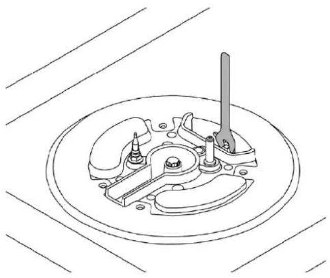
Proceed as follows to change the burner nozzles: lift the flame spreaders and unscrew the nozzles using a 7 mm spanner, then replace them with those required for new gas in accordance with the TABLE (each nozzle has the number indicating its diameter stamped on its body).
Keep the old nozzles in case they are required in future.
natural_image
Technical line drawing of a mechanical assembly with a central tool and circular base (no text or symbols)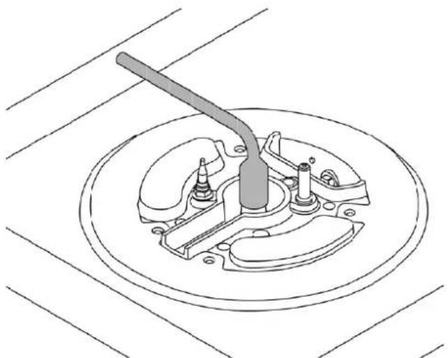
natural_image
Technical line drawing of a mechanical switch assembly (no text or symbols)
Step 2: Burner minimum adjustment
Light the nozzle and turn the knob to the MINIMUM position (small flame).
2) Remove the knob, which is simply friction fitted to the spindle.
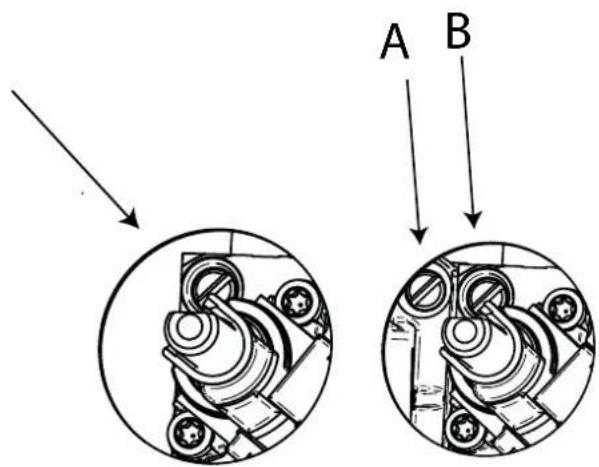
3) Use a small screwdriver on the gold screw next to the knob shank (see figure) and turn the flow control screw to the left or right until the burner flame is suitably regulated to the MINIMUM setting.
For dual burner knobs there are two flow control screws: screw A to adjust the inner ring, and screw B to adjust the outer ring.
4) Ensure that, when moving from the MAXIMUM to the MINIMUM position, the flame does not go out.
WARNING: The above-mentioned regulation must only be performed for burners running on natural gas (methane): when using LPG (butane or propane), the screw must be locked all the way to the right.
ELECTRICAL CONNECTION
The electrical connection must be made in accordance with applicable standards and legislation.
Before connecting up the appliance, check that:
- The mains electricity supply matches the characteristics indicated on the appliance data plate.
- The circuit wiring and outlet are equipped with a compliant earth connection.

When the oven is connected to the mains power supply via a socket:
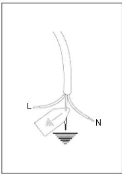
- Wire a plug onto the power cable which must comply with applicable standards in the country of use; the plug (and its fuse, where applicable) must be suitable for the rated load specified on the appliance data plate. Connect the cores of the cable in accordance with the figure, ensuring you follow the harmonised wiring colour scheme:
L (live/hot/phase) = brown wire N (neutral) = blue wire earth "⊥" symbol = yellow/green wire
- The power cable must be positioned in such a way that it does not reach a temperature of 90^ at any point.
- Do not use adapters, extension leads, gang sockets etc. as these could cause loose contacts and overheat.
When the appliance is to be hard-wired to the mains circuit:
- The circuit must be fitted with a omnipolar circuit breaker of suitable capacity for the appliance's rated load.
- The earth conductor must not be switched by the breaker and must be connected to the earthing system.
- As an alternative, an RCBO may also be used, or RCD protection in addition to or instead of a fuse or MCB, depending on the applicable electrical code.
WARNING: The appliance complies with the requirements of 2016/426/EU (Gas Appliances Regulation), 2014/35/EU (Low Voltage Directive) on electrical safety, and 2014/30/EU (Electromagnetic Compatibility Directive).
MAINTENANCE
REPLACING COMPONENTS
Isolate the appliance's gas and electricity supplies before performing any maintenance.
Contact an authorised service centre if functional components such as burners, taps and electrical components require replacement.
WARNING:
If the power cable requires replacement, the installer/maintenance technician must use H05VV-F 3x0.75 mm ^2 cable and leave the earth conductor around 2 cm longer than the live and neutral wires. They must also comply with the instructions given for the initial electrical connection.
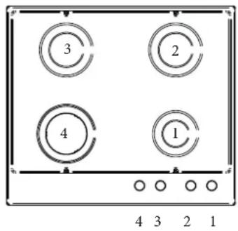
DESCRIPTION OF HOBS
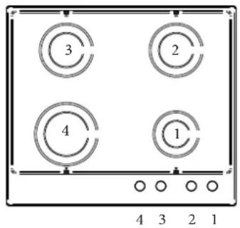
CONTROLS / BURNERS
1 Front right auxiliary burner
2 Rear right semi-rapid burner
3 Rear left semi-rapid burner
4 Front left rapid burner
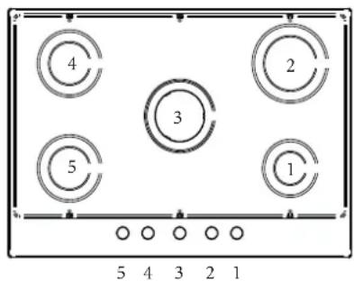
CONTROLS / BURNERS
1 Front right auxiliary burner
2 Rear right semi-rapid burner
3 Rear left semi-rapid burner
4 Front left crown burner
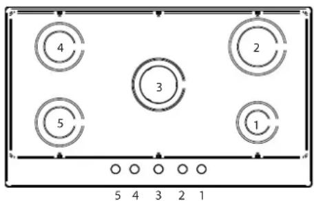
CONTROLS / BURNERS
1 Front right auxiliary burner
2 Rear right rapid burner
3 Central crown burner
4 Rear left semi-rapid burner
5 Front left semi-rapid burner
CONTROLS / BURNERS
1 Front right auxiliary burner
2 Rear right rapid burner
3 Central dual burner or crown burner
4 Rear left semi-rapid burner
5 Front left semi-rapid burner
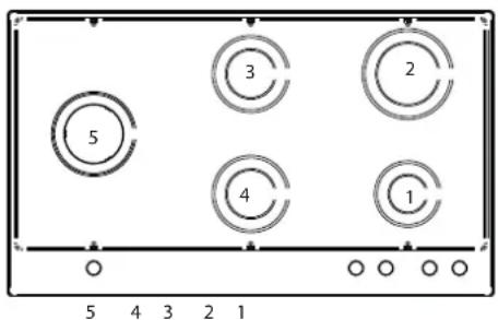
CONTROLS / BURNERS
1 Front right auxiliary burner
2 Rear right rapid burner
3 Rear central semi-rapid burner
4 Front central semi-rapid burner
5 Left side dual burner or crown burner

USE
BURNERS AND GRATES
The flame spreaders and burner caps must be correctly positioned in order for the hob to operate properly.
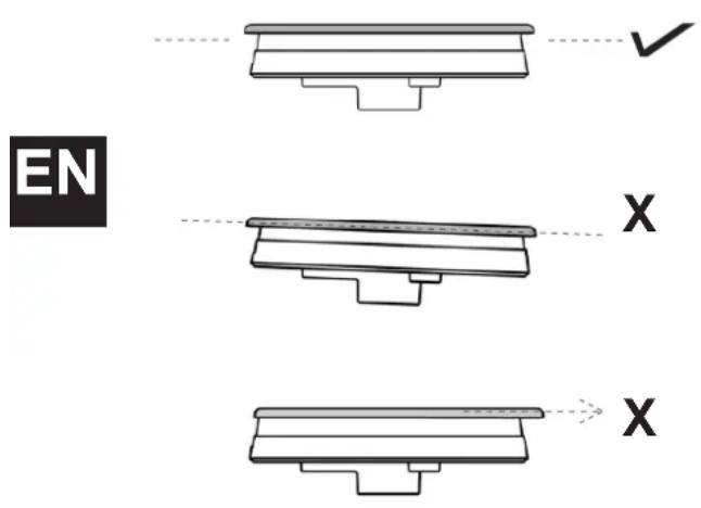
Incorrect positioning of the flame spreaders and caps can lead to burner damage.
The grids must be positioned in their seats inside the hob.
USING THE BURNERS
Next to each knob is an indication of which burner it operates.
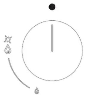
Turn the knob corresponding to the selected burner to the left to the MAXIMUM position (large flame).
Press the knob to start the gas flow and ignite the burner.
When the burner lights, keep the knob held down for around ten seconds, then release.
If the burner goes out after releasing the knob, repeat the entire operation.
To shut off the burner, turn the knob to the right to the zero position.
natural_image
Simple line drawing of a clock face with hour, minute, and second hands (no text or symbols)USING DUAL BURNERS (where applicable)
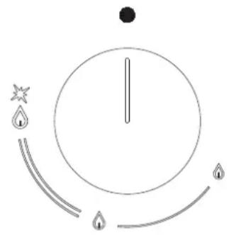
Dual burners offer greater flexibility, as it is possible to light both rings or just the inner ring.
Turn the corresponding knob to the left to the MAXIMUM position (1).
Press the knob to start the gas flow and ignite the burner.
When the burner lights, keep the knob held down for around ten seconds, then release.
If the burner goes out after releasing the knob, repeat the entire operation.
In position 2 the outer ring is at the minimum setting and the ring crown is at the maximum.
In position 3 the inner ring is at the maximum setting and the outer ring is off.
In position 4 the inner ring is at the minimum setting and the outer ring is off.
natural_image
Simple circular diagram with a vertical line, star, droplet, and droplet symbols at the bottom (no text or labels)Tips for optimum burner use:
- Use appropriate pans for each burner (see table).
- When the pan boils, move the knob to the MINIMUM position.
• Always use pans with lids.
| BURNER PAN | DIAMETER(RECOMMENDED) cm |
| Auxiliary 12 - 14 | |
| Semi-rapid | 14 - 26 |
| Rapid | 18 - 26 |
| Crown | 22 - 26 |
| Dual | 22 -26 |
SAFETY SYSTEMS
A flame sensor (thermocouple) is installed on each burner to prevent gas from coming out if the flame is accidentally extinguished.
If there is a blackout of the electricity supply, the hob will keep working without any danger.
MANUAL IGNITION
In the event of a power failure, the burners can be ignited manually.
Turn the knob corresponding to the selected burner to the left to the MAXIMUM position (large flame).
Press down on the knob to start the flow of gas, then bring a lighter or flame up to the burner.
When the burner lights, keep the knob held down for around ten seconds, then release.
ACCESSORIES
Wok Adapter
Supplementary grid to be used on crown burners with concave-bottom cookware.
Coff ee Pot Reducer
Supplementary grid to be used on the auxiliary burner for coffee pots or cookware with a diameter below 12 cm.
CLEANING THE APPLIANCE
Before performing any cleaning operation, wait for all parts to cool down and isolate the hob's electricity and gas supply.
Cleaning the hob:
The burner heads, enamelled steel grids, enamelled caps and flame spreaders must be regularly cleaned with warm soapy water then rinsed and dried thoroughly.
Any liquid which should overflow from the cookware must always be removed with a cloth. If it is difficult to open or close one of the gas taps, do not force it! Request urgent assistance from the technical support network.
Cleaning Enamelled Parts:
To maintain the characteristics of the enamelled components, they should be cleaned frequently with soapy water. Never use scouring powders.
Do not leave acidic or basic substances (vinegar, lemon juice, salt, tomato juice etc.) sitting on enamelled parts, and do not wash enamelled parts when they are still hot.
Cleaning Stainless-Steel Parts
Clean the components with soapy water and then dry them with a soft cloth. The shine can be maintained by periodic use of commonly available products. Never use scouring powders or pads.
Cleaning the Burner Flame Spreaders:
As they are simply resting in position, they can be cleaned simply by removing them from their seats and washing them with soapy water. Do not immerse in water or wash them under running water. After drying them thoroughly and checking that the holes are not blocked, return them to their correct position.
Cleaning Glass Hobs:
To degrease, use washing-up liquid and vinegar, then rinse; otherwise, clean with washing-up liquid, rinse, then pass over with a moist cloth before drying.
To remove encrusted food, soak with soapy water or washing-up liquid for a few minutes. After a few minutes, rinse and wash the hob.
Avoid anti-limescale, abrasive and multi-purpose products, as they will affect the look of the glass after a while.
Cleaning the Hob Grids:
Do not wash the grids in the dishwasher.
White residue on the grids is due to normal contact with cookware, and not indicative or defects or abrasions in the enamel.

TROUBLESHOOTING
In some cases operational faults can be easily resolved.
Read the following tips before contacting technical support.
The burner does not light.
Check that there is no food residue between the igniter and burner.

Check that the gas and electricity supplies are present.
Check that the burners are correctly located and are not wet.
The igniter is still not working.
Water has probably entered the hob during cleaning. Isolate the electricity supply and wait a few hours to allow it to dry thoroughly.
The igniter does not work
Check that the electrical isolation switch or circuit breaker is in the on position, and that there are no problems with the electricity supply.
The burner flame is not even.
The burner is not correctly positioned.
The burner holes are dirty or blocked by water.
The knob will not stay in place.
The knob clip is broken: call customer service for a replacement.
There is no gas flow.
Check that the gas isolation tap is not closed/the cylinder is not empty.
WARRANTY AND CUSTOMER SERVICE: WWW.BERTAZZONI.COM

INSTRUCTIONS D'INSTALLATION ET D'UTILISATION PLAQUES DE CUISSON ENCASTRABLES AU GAZ TYPE P93V (MÉTAL) TYPE P94GV (VERRE)


TABLE DES MATIÈRES
AVERTISSEMENTS 4
RESPONSABILITÉ DU FABRICANT 4
PROTECTION DE L'ENVIRONNEMENT 4
CONSIGNES GÉNÉRALES DE SÉCURITÉ 5
AVERTISSEMENTS D'UTILISATION 5
PLAQUE D'IDENTIFICATION 5
EMBALLAGES EN PLASTIQUE 5
MANUEL TECHNIQUE POUR L'INSTALLATEUR 6
INTÉGRATION DE LA PLAQUE DE CUISSON 6
AVERTISSEMENTS IMPORTANTS 6
INSTALLATION AU-DESSUS D'UN FOUR ENCASTRÉ 7
INSTALLATION AU-DESSUS D'UN LOGEMENT OU DE TIROIRS 7
FIXATION DE LA PLAQUE DE CUISSON 8
VENTILATION AMBIANTE 8
EMPLACEMENT ET AÉRATION 9
RACCORDEMENT DE LA PLAQUE À L'ALIMENTATION EN GAZ 9
PRÉCAUTIONS D'UTILISATION DU PRODUIT AVEC DU GAZ GPL 10
CONVERSION DU GAZ 11
BRANCHEMENT ÉLECTRIQUE 12
ENTRETIEN 12
REMPLACEMENT DES COMPOSANTS 12
DESCRIPTION DES PLAQUES DE CUISSON 13
UTILISATION 14
BRÛLEURS ET GRILLES 14
UTILISATION DES BRÛLEURS 14
SYSTÈME DE SÉCURITÉ 15
ALLUMAGE MANUEL 15
ACCESSOIRES 15
NETTOYAGE DE L'APPAREIL 15
DYSFONCTIONNEMENT 16
MESSAGE DU PRÉSIDENT
natural_image
Technical diagram of a five-membered fan or vent with circular cutouts and a central hub, shown with dimension labels H and L (no text or symbols on the diagram itself)AVERTISSEMENTS IMPORTANTS
natural_image
Technical line drawing of a mechanical assembly with no visible text or symbols
natural_image
Isometric line drawing of a 3D architectural or mechanical structure with two rectangular compartments and a gray panel on the left (no text or symbols)FIXATION DE LA PLAQUE DE CUISSON
natural_image
Technical line drawing of a mechanical assembly with no visible text or symbols
natural_image
Line drawing of a screwdriver adjusting a mechanical component with a rotating knob (no text or symbols)VENTILATION AMBIANTE
natural_image
Isometric line drawing of a room interior with a central cabinet and directional arrow (no text or symbols)EMPLACEMENT ET AÉRATION
natural_image
Isometric line drawing of a kitchen furnace and stove inside a storage unit (no text or symbols)Figure A
natural_image
Isometric line drawing of a room interior with a cabinet and wall-mounted unit (no text or symbols)Figure B
RACCORDEMENT DE LA PLAQUE À L'ALIMENTATION EN GAZ
natural_image
Technical line drawing of a mechanical assembly with no visible text or symbolsPRÉCAUTIONS D'UTILISATION DU PRODUIT AVEC DU GAZ GPL
natural_image
Technical line drawing of a mechanical assembly with a central tool and circular base (no text or symbols)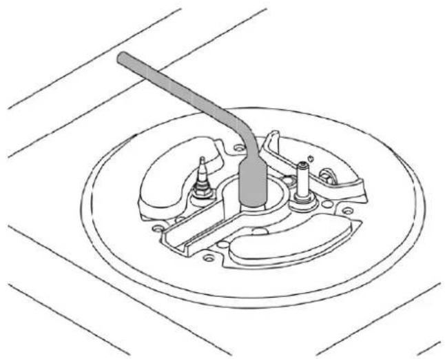
natural_image
Technical line drawing of a mechanical switch assembly (no text or symbols)natural_image
Simple line drawing of a cable with labeled points L and N, and a ground symbol below (no text or symbols beyond labels)REPLACEMENT DES COMPOSANTS
natural_image
Simple line drawing of a circle with a vertical line, star and droplet symbols, and a curved arrow pointing inward (no text or labels)natural_image
Simple line drawing of a clock face with hourglass, stars, and water droplets (no text or symbols)natural_image
Technical diagram of a gas stove with five circular vented fans and a central hub, labeled with height H and length L (no text or symbols on the diagram itself)MANUAL TÉCNICO PARA EL INSTALADOR
natural_image
Technical line drawing of a mechanical assembly with no visible text or symbols
natural_image
Isometric line drawing of a 3D architectural or mechanical structure with two rectangular components and a gray panel on the left (no text or symbols)natural_image
Technical line drawing of a mechanical assembly with no visible text or symbolsnatural_image
Diagram showing a screwdriver adjusting a mechanical component with a wrench, no text or symbols presentnatural_image
Isometric line drawing of a room interior with a central cabinet and directional arrow (no text or symbols)natural_image
Isometric line drawing of a kitchen furnace with a chimney and stove (no text or symbols)Ilustración A
natural_image
Isometric line drawing of a room interior with a cabinet and wall-mounted fixture (no text or symbols)Ilustración B
natural_image
Technical line drawing of a mechanical assembly with no visible text or symbolsPRECAUCIONES RELATIVAS AL USO DEL PRODUCTO CON GAS GLP:
natural_image
Technical line drawing of a mechanical assembly with a central tool and circular base (no text or symbols)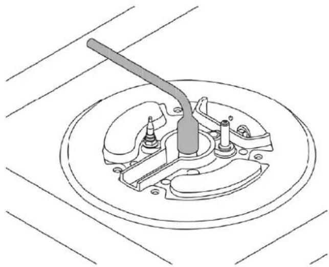
natural_image
Technical line drawing of a mechanical switch assembly on a circular base (no text or symbols)natural_image
Simple line drawing of a cable with labeled terminals L and N, and a small rectangular object at the base (no text or symbols beyond labels)
natural_image
Simple line drawing of a circle with a vertical line, star and droplet symbols, and a dot above it (no text or labels)natural_image
Simple circular diagram with a vertical line, three water droplets below, and a black dot above (no text or symbols)natural_image
Technical line drawing of a mechanical assembly with no visible text or symbols
natural_image
Technical line drawing of a mechanical assembly with no visible text or symbols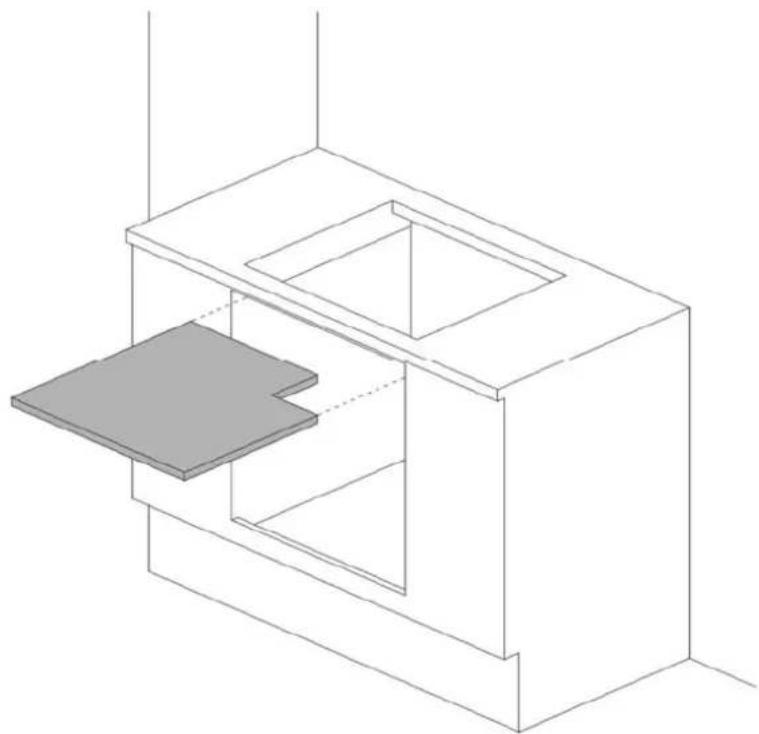
natural_image
Isometric line drawing of a 3D architectural or mechanical structure with two rectangular compartments and a gray panel on the left (no text or symbols)natural_image
Technical line drawing of a mechanical assembly with no visible text or symbolsnatural_image
Line drawing of a screwdriver adjusting a mechanical component with a curved tool (no text or symbols)natural_image
Isometric line drawing of a room interior with a central cabinet and wall-mounted fixture (no text or symbols)natural_image
Isometric line drawing of a mechanical device inside a transparent enclosure, showing internal components and a directional arrow (no text or symbols)(Σχήμα Α)
natural_image
Isometric line drawing of a room interior with a vent and airflow direction indicator (no text or symbols)(Σχήμα Β)
natural_image
Technical line drawing of a mechanical assembly with no visible text or symbolsnatural_image
Technical line drawing of a mechanical component with a central shaft and housing (no text or symbols)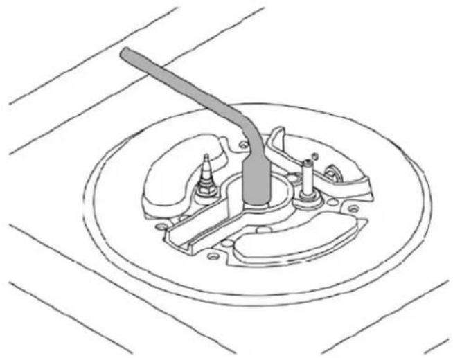
natural_image
Technical line drawing of a mechanical assembly with a lever and housing (no text or symbols)natural_image
Simple line drawing of a clock face with hourglass and water droplets, no text or symbols presentnatural_image
Simple circular diagram with arrows and symbols, no readable text or labels- DALLA SCRIVANIA DEL PRESIDENTE
- MANUALE TECNICO PER L'INSTALLATORE
- ALLACCIAMENTO DELL'APPARECCHIO ALLA RETE GAS
- PRECAUZIONI PER L'UTILIZZO DEL PRODOT- TO CON GAS GPL:
- UTILIZZO BRUCIATORE DUAL (dove previsto)
- INSTALLATION AND USER MANUAL
- BUILT-IN GAS HOBS
- MODEL P93V (METAL)
- MODEL P94GV (GLASS)
- CONTENTS
- FROM THE DESK OF OUR PRESIDENT
- INTRODUCTION
- READ THESE INSTRUCTIONS CAREFULLY BEFORE INSTALLING AND USING THE APPLIANCE.
- THIS APPLIANCE IS DESIGNED FOR NON-PROFESSIONAL, DOMESTIC USE.
- MANUFACTURER LIABILITY
- ENVIRONMENTAL PROTECTION
- GENERAL SAFETY INSTRUCTIONS
- INSTRUCTIONS FOR USE
- APPLIANCE DATA PLATE
- PLASTIC PACKAGING
- TECHNICAL INSTALLATION INSTRUCTIONS
- Ensure all necessary PPE is used when carrying out the installation
- INSTALLING THE HOB
- IMPORTANT INFORMATION
- INSTALLING THE HOB ABOVE AN OVEN
- INSTALLING THE HOB ABOVE A CUPBOARD OR DRAWERS
- HOB FASTENING
- ROOM VENTILATION
- LOCATION AND VENTILATION
- CONNECTING THE APPLIANCE TO THE GAS SUPPLY
- PRECAUTIONS WHEN USING THE PRODUCT WITH LPG (BUTANE/PROPANE)
- GAS CONVERSION
- WARNING!
- Step 1: Replacing the nozzles
- Step 2: Burner minimum adjustment
- ELECTRICAL CONNECTION
- MAINTENANCE
- REPLACING COMPONENTS
- WARNING:
- DESCRIPTION OF HOBS
- CONTROLS / BURNERS
- USE
- BURNERS AND GRATES
- USING THE BURNERS
- USING DUAL BURNERS (where applicable)
- SAFETY SYSTEMS
- MANUAL IGNITION
- ACCESSORIES
- Wok Adapter
- Coff ee Pot Reducer
- CLEANING THE APPLIANCE
- Cleaning the hob:
- Cleaning Enamelled Parts:
- Cleaning Stainless-Steel Parts
- Cleaning the Burner Flame Spreaders:
- Cleaning Glass Hobs:
- Cleaning the Hob Grids:
- TROUBLESHOOTING
- The burner does not light.
- The igniter is still not working.
- The igniter does not work
- The burner flame is not even.
- The knob will not stay in place.
- There is no gas flow.
- INSTRUCTIONS D'INSTALLATION ET D'UTILISATION PLAQUES DE CUISSON ENCASTRABLES AU GAZ TYPE P93V (MÉTAL) TYPE P94GV (VERRE)
- TABLE DES MATIÈRES
- MESSAGE DU PRÉSIDENT
- AVERTISSEMENTS IMPORTANTS
- FIXATION DE LA PLAQUE DE CUISSON
- VENTILATION AMBIANTE
- EMPLACEMENT ET AÉRATION
- RACCORDEMENT DE LA PLAQUE À L'ALIMENTATION EN GAZ
- PRÉCAUTIONS D'UTILISATION DU PRODUIT AVEC DU GAZ GPL
- REPLACEMENT DES COMPOSANTS
- MANUAL TÉCNICO PARA EL INSTALADOR
- PRECAUCIONES RELATIVAS AL USO DEL PRODUCTO CON GAS GLP:
Brand : BERTAZZONI
Model : P905LMODNE
Category : Cooker