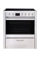
FEC76B3 - Cooker Porter & Charles - Free user manual and instructions
Find the device manual for free FEC76B3 Porter & Charles in PDF.


| Product type | Gas range with electric oven |
| Brand | Porter & Charles |
| Model | FEC76B3 |
| Dimensions (H x W x D) | 920 x 762 x 640 mm |
| Weight | Approximately 60 kg (not specified, estimate) |
| Power supply | 208/240 V ~ 60 Hz, 30 A (gas cooktop) / 40 A (oven) |
| Gas type | Natural gas or propane (convertible) |
| Number of burners | 4 (1 semi-rapid, 1 rapid, 1 auxiliary, 1 wok) |
| Burner power (max) | Wok burner: 17,500 BTU/h (natural gas) |
| Oven type | Electric, fan-forced and convection |
| Oven functions | Convection, grill, ventilated grill, baking, pizza, defrosting, lighting |
| Oven capacity | Approximately 100 L (estimate for 76 cm) |
| Electronic programmer | Timer, delayed cooking, automatic shut-off |
| Self-cleaning panels | Yes, on side and rear walls |
| Oven lighting | Halogen bulb 40 W |
| Warming drawer | Yes, 200 W (keep warm) |
| Safety | Safety thermostat, automatic ignition, gas safety shut-off |
| Cleaning | Removable rack, removable door, removable base |
| Reparability | Spare parts available via EURO-PARTS (1-800-678-8352) |
| Warranty | 2 years (parts and labor in metropolitan areas) |
Frequently Asked Questions - FEC76B3 Porter & Charles
User questions about FEC76B3 Porter & Charles
0 question about this device. Answer the ones you know or ask your own.
Ask a new question about this device
Download the instructions for your Cooker in PDF format for free! Find your manual FEC76B3 - Porter & Charles and take your electronic device back in hand. On this page are published all the documents necessary for the use of your device. FEC76B3 by Porter & Charles.
USER MANUAL FEC76B3 Porter & Charles
Congratulations on the purchase of your Porter&Charles appliance.
We are sure it will provide many years of great cooking experience.
You may find that it has different features and characteristics to your last appliance.
It is essential you read this operation manual thoroughly to fully understand all of the various functions and operations. Experiment with your cooking and take advantage of the features your new appliance offers.
This manual should be retained for future reference. Should ownership of the appliance be transferred, please ensure that the manual is also passed onto the new owner.
Contents
A - Installation check and warnings Page 3 - 7
B - Range Measurements Page 8 - 11
C - Electrical Requirements Page 12
D- Using the appliance for the first time Page 13 - 14
E- Accessories Page 14-15
F- Electronic Programmer Operation Page 16 - 18
G- Gas Cooktop Control Panel Page 19
H- Gas Cooktop Control Functions Page 20
I- Ceramic Cooktop Control Panel Page 21 - 22
L-Ceramic Cooktop Functions Page 23
M- Oven Functions & Control Panel Page 24 - 30
N- Cleaning and maintenance Page 31 - 35
P- Trouble shooting guide Page 35
Wiring diagram Page 36-41
Q- Warranty Page 42
A - Installation instructions check and warnings
WARNING
This appliance is not intended for use by persons (including children) with reduced physical, sensory or mental capabilities, or lack of experience and knowledge, unless they have been given supervision or instruction concerning use of the appliance by a person responsible for their safety.
Children should be supervised to ensure that they do not play with the appliance.
WARNING
During use the appliance becomes hot. Care should be taken to avoid touching heating elements inside the oven.
IMPORTANT:
Please ensure that the cut out measurement, venting and wiring is as specified in the relevant section B of this manual.
A licensed electrician with relevant qualifications must perform electrical work when installing or servicing the appliance. The supply cable and fuse rating must be suitable for the appliance. You must never repair or replace any part of the appliance unless specifically recommended in the operation manual.
Ventilation opening must not be covered or obstructed in any way.
VENTILATION
The room containing this range should have an air supply in accordance with local regulations.
- All rooms require an open window, or equivalent and some rooms will require a permanent vent also.
- For room areas up to 5m 2 an air vent of 100cm 2 is required.
- For room areas between 5m 2 and 100cm 2 an air vent of 50cm 2 is required.
- If the room is greater than 5m 2 and has a door that opens directly to the outside, then no air vent is required.
- If there are other fuel burning appliances in the same room, check your local regulations to determine the air vent requirements.
Cooking appliances must always discharge the flue gases into special hoods (fig.1-C), which must be connected to chimneys, flue pipes or have direct access to the outside. If it is not possible to connect a hood, an electric fan can be fitted to a window or a wall (fig.1-E), which must be turned on when the cooker is on, as long as ventilation standards are strictly adhered to.
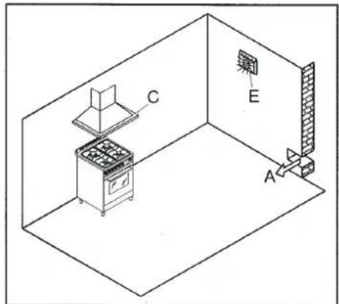
Fig.1
When ranges are installed in close proximity to vinyl finish cabinets, those materials should be able to withstand temperatures up to 75°C.
Alternatively, heat insulating barriers should be installed to avoid any deterioration to the finish.
The equipment must not be installed near inflammable materials, such as curtains, cloths, etc.
Pay particular attention to the position of the electric cable and gas pipe: they must not touch any hot parts of the oven.
The manufacturer will not accept responsibility for damages to cabinetry where manufacturer's installation guidelines were not adhered to.
CONVERTING TO LPG
Burners: auxiliary, semi-rapid, rapid, wok burner.
These burners are all fitted with injectors designed to create a primary input of air gauged for each type of gas.
Proceed as follows in order to convert from one type of gas to another:
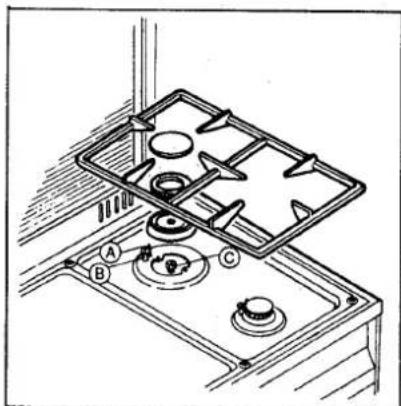
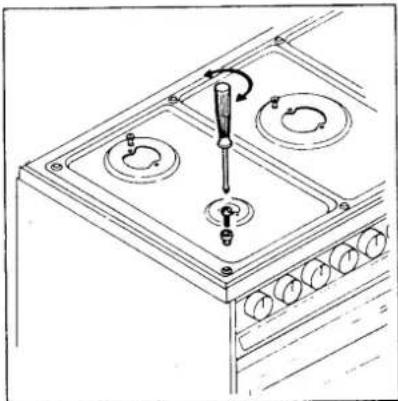
- remove the grids, covers, flame diffuser and the burner supports (fig. 7);
- replace the injectors as indicated in 7/C according to the type of gas used (see table 1);
- put the burner supports, flame diffusers, covers and grids back in position;
- regulate the minimum output following the instructions in paragraph 1.7.
NOTE: Regulator needs to be set for the gas being used.
Table 1
natural_image
Line drawing of a kitchen appliance with a screwdriver inserted into a tray (no text or symbols)Fig.7
7/C
REGULATING THE MINIMUM OUTPUT OF THE COOKTOP BURNERS
Normal/valve taps:
Ignite the burners and turn the knob to the minimum position. Remove the knob and insert a small flat-head screwdriver into the rod or through the holes on the side of the control panel, in accordance with the type (fig. 8 A/B). Adjust the screw until the flame is lowered but stable, even when rapid changes are made from the maximum to the minimum position with the burner cold. If safety taps are fitted, let the burner run on minimum for a few minutes to ensure that the device does not cut in. If it does, increase the minimum.
N.B. For liquid gas settings, the burner minimum must be set by fully tightening the tap by-passes.
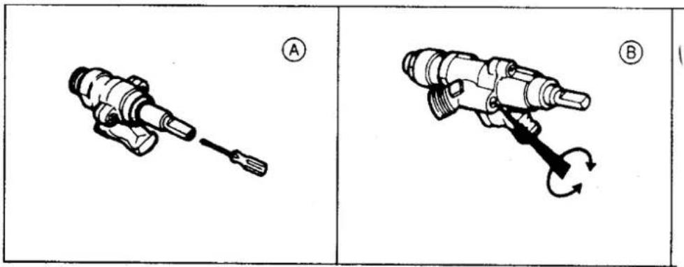
Fig.8

WARNINGS:
- Using a gas cooktop produces heat and humidity in the room where it is installed. Ensure the room is well ventilated by keeping all the natural air vents open or by installing an extraction hood with flue pipe.
- Intensive or extensive use of the range may require supplementary ventilation e.g. opening a window, or more efficient ventilation e.g. increasing the capacity of the mechanical ventilation, if installed.
- If the burner flames accidentally go out due to excessive airflow, turn off the KNOB and wait for at least one minute before igniting.

N.B. When the burners are alight, there must not be any draughts inside the room in that they may affect the flame or even blow it out.
INSTALLATION INSTRUCTIONS
DO NOT LIFT RANGE BY THE FRONT DOOR HANDLE AS THIS WILL DAMAGE THE UNIT.
The operations indicated below must be followed by a qualified technician, in compliance with local regulations.
The supplier refuses all responsibility for damages to person or property, resulting from the failure to comply with such provisions.
All units are 208/240Volt power and 60Hz.
The appliance is designed to be used near heat resistant pieces of furniture or kitchen cabinetry only.

ATTENTION
Disregard of this precaution could cause the incorrect operation of the touch control system of the cooktop and affect the product warranty provisions.

WARNING:
All aspects of the installation must conform to North American wiring standards, as well as your local electrical and building codes and regulations, and any other applicable requirements and conditions of your local power supply authority. Your appliance must be properly installed and grounded by a qualified and licensed technician.
208/240Volt 60 Hz 30Amp/40Amp service
Incorrect installation of the appliance, resulting from the installer not following the detailed installation specifications, can affect the performance of the appliance.
CONNECTION TO THE GAS SUPPLY: CURRENT INSTALLATION STANDARDS
The range should be connected according to local regulations, using either a rigid or flexible connections.
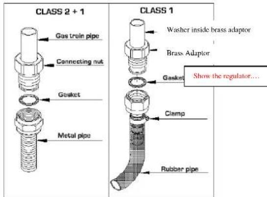
a) For building in: Use a continuous flexible stainless steel pipe, as per current installation standards, which can be extended to a maximum of 2000mm.; the ends of the pipe must be fitted with an ISO 228/1coupling and gasket or an ISO 7/1 threaded coupling with mechanical gasket.
b) For free standing: A non-metallic flexible pipe can be used as long as it complies with current standards and the following installation instructions are observed: the pipe must be longer than 400mm and shorter than 1500mm; it must not exceed 50°C at any point; it is not pulled or twisted; it cannot be choked and the entire edges, sharp corners or other similar hazards.
Before connecting the non-metallic flexible pipe, the brass adapter and gasket supplied with the range and/or available from the reseller must be fitted to the pipe/gas train on the back of the range. The regulator provided should be positioned between the brass adapter and the non metallic flexible pipe.
c) A certified gas plumber must complete the installation and meet with local regulation requirements for gas connections. Where the unit has an armour cable a certified electrician must complete the electrical connection. The white, or neutral wire will not be used and must be capped using a marrette.

WARNINGS:
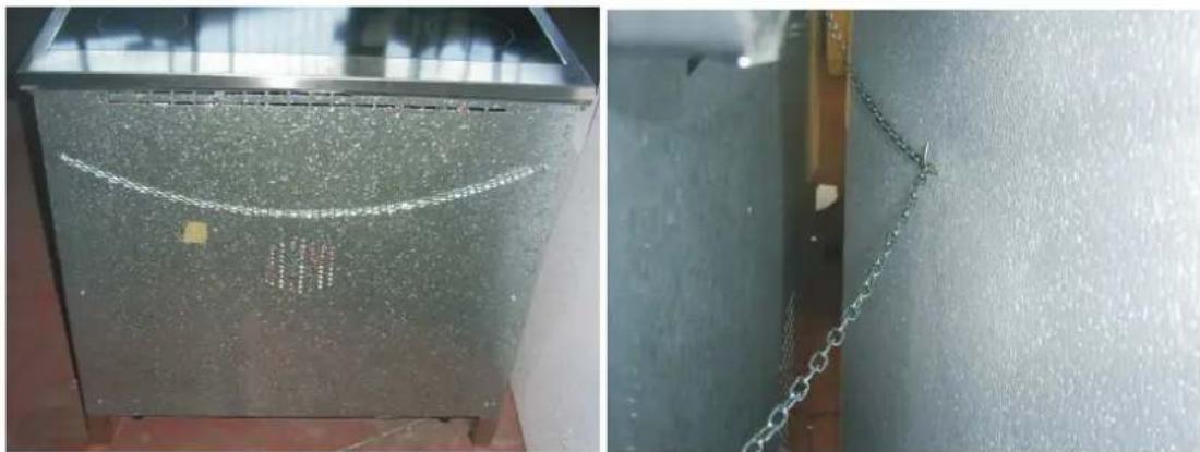
In order to prevent tipping of the appliance, the safety chain must be attached to a hook secured to the wall.
(PLEASE NOTE: The fixing hook is not provided as the type will depend on the construction of the wall to which it will be drilled and fitted. The installer should provide the fixing hook per customer request).
natural_image
Two-panel image showing a metallic panel with a curved white line and a chain attached to a wall (no text or symbols visible)B - Range Measurements
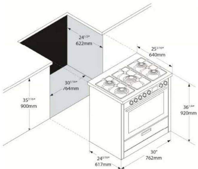
Measurements
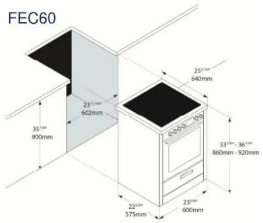
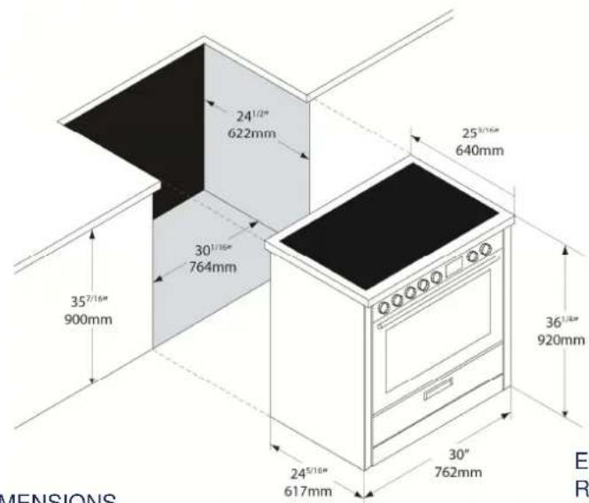
Please note that all dimensions provided are in millimeters (mm) and inches. The sizes allow for only a small degree of error so all cut-outs must be precise and square.
If the range is placed on a base, measures have to taken to prevent the appliance slipping from the base.
RANGE DIMENSIONS
D: 253/16 • W: 235/8 • H: 337/8 - 361/4
D: 640 mm · W: 600 mm · W: 860 mm - 920 mm

RANGE DIMENSIONS
• D: 25 3/16 " • W: 23 5/8 " • H: 33 7/8 " - 36 1/4 "
• D: 640 mm • W: 600 mm • W: 860 mm – 920 mm
Rear View
natural_image
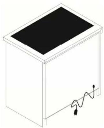
Simple line drawing of a rectangular box with a black top and a small cable attached to the right side (no text or symbols)ELECTRICAL REQUIREMENTS
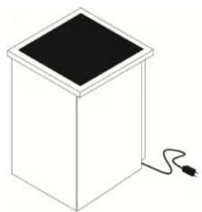
• 208/240 Volt, 60Hz, 40AMP
- P&C ranges are supplied with a 5' long electrical.
Rear View
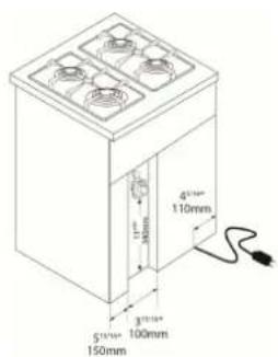
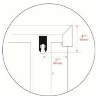
ELECTRICAL REQUIREMENTS
• 208/240 Volt, 60Hz, 40AMP
- P&C ranges are supplied with a 5' long electrical. 8
FEC76
Rear View
natural_image
Isometric line drawing of a rectangular box with a black top and a small plug inserted into the bottom (no text or symbols)RANGE DIMENSIONS
D: 25 3/16 " • W: 30" • H: 36 1/4 "
D: 640 mm · W: 762 mm · W: 920 mm
ELECTRICAL REQUIREMENTS
• 208/240 Volt, 60Hz, 40AMP
- P&C ranges are supplied with a 5' long electrical.
FEG76
Rear View
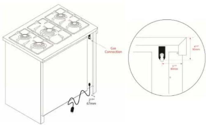
RANGE DIMENSIONS
D: 253/16 • W: 30 • H: 361/4
• D: 640 mm • W: 762 mm • W: 920 mm
ELECTRICAL REQUIREMENTS
• 208/240 Volt, 60Hz, 40AMP
- P&C ranges are supplied with a 5' long electrical.
FEC90
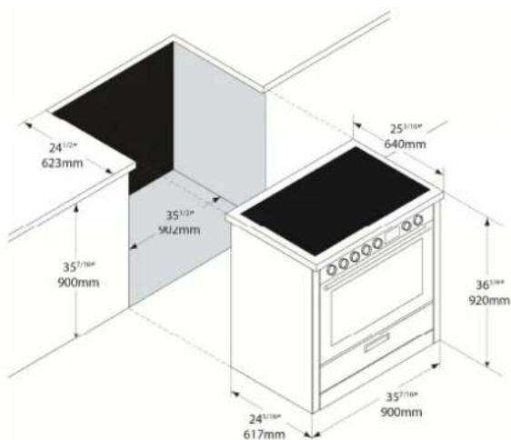
RANGE DIMENSIONS
D: 25 3/16 " • W: 35 7/16 " • H: 36 1/4 "
• D: 640 mm • W: 900 mm • W: 920 mm
FEG90
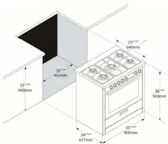
RANGE DIMENSIONS
• D: 253/16 • W: 357/16 • H: 361/4
• D: 640 mm • W: 900 mm • W: 920 mm
Rear View
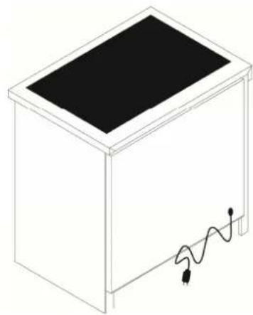
natural_image
Isometric line drawing of a rectangular box with a black top and a wavy bottom edge, no text or symbols present.ELECTRICAL
REQUIREMENTS
• 208/240 Volt, 60Hz, 40AMP
- P&C ranges are supplied with a 5' long electrical.
Rear View
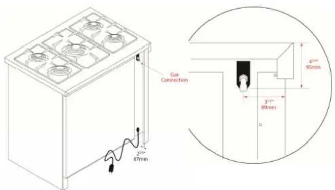
ELECTRICAL
REQUIREMENTS
• 208/240 Volt, 60Hz, 40AMP
- P&C ranges are supplied with a 5' long electrical.
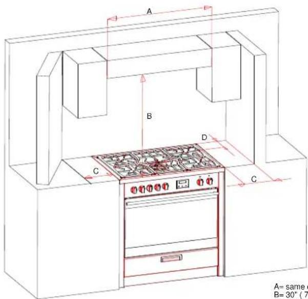
A= same dimension of appliance
B=30" (762mm)
C=4,5" (110mm)
D=8,1(200mm)
C – Electrical requirements

WARNING:
All aspects of the installation must conform to the requirements of the standard North American wiring rules, as well as your local electrical and building codes and regulations,
and any other applicable requirements and conditions of your local power supply authority. A licensed electrician must perform the electrical work when installing this appliance. The supply cable and fuse rating must be suitable for the appliance. The range is supplied with a 40AMP corded plug.
240Volt 60Hz 40AMP (range with ceramic cooktop)
240Volt 60Hz 30AMP (range with gas cooktop)
Note:
To the electrician – please ensure sufficient supply cable is provided to allow the appliance to be removed from the cavity should any servicing be necessary. This will also allow easy connection of the supply.
Voltage supply connection, if unit not supplied with power cord
To connect the electrical supply:
1- This appliance must be installed individually on a separate and distinct final sub-circuit.
2- Ensure the supply cable and fuse rating are suitable for the appliance (see the electrical loading).
3- Remove the cover plate by undoing the screw.
4- Fit a suitable entry bush to the conduit entry on the rear left of the appliance (with the rear toward you) and feed the fixed wiring through.
5- Connect the wiring to the terminal block using the screw connections provided. Ensure the wires are properly secured to prevent any high resistance electrical connection.
6- Replace the cover plate making certain that the supply wiring is clear of any metal work and the screws.
7- If the supply cord is damaged, it must be replaced by the manufacturer, its service agent or similarly qualified persons in order to avoid hazard
When connected to a sub circuit, protected by a circuit breaker, it is recommended the circuit breaker be the same as the total rating of the appliance.
To fully disconnect the power supply, it is necessary to have a proper mean in the fixed wiring in accordance with the wiring rules. It must have full disconnection under overvoltage category III conditions.
If you wish a direct connection to the line, it is necessary to use a double pole switch, with a minimum opening between the contacts of 3mm. suitable for the purpose and in compliance with local regulations (the green ground cable should not be interrupted by the switch).
D – Using the appliance for the first time
After installation remove all notification labels (not identification or warning labels) and packaging materials. After cleaning make sure cleaned surfaces are thoroughly rinsed and wiped dry using a clean, soft cloth.
Power on

NOTE: Oven will not operate unless the clock is set.
When power is first applied the display will flash and shows 00:00.
The time of day is displayed in digital 24 hour format (e.g.: 18:00 is 6:00 pm).
Burning in
Before cooking in the appliance an initial pre-heating is required to burn off the fine oil film used to protect the elements for shipping. Select a cooking mode and set the oven temperature to 180° C.
With the oven door closed, leave for approximately 5 minutes.
Repeat the above step for each cooking mode.
After completing the above make sure all controls are turned off. The oven is now ready for cooking and grilling.
DO NOT use aluminum foil on the base of ovens
The use of foil on the base of the oven to avoid spillage and improve cleaning is not recommended. The bottom element is concealed under the base of the oven liner (not exposed). Foil or dishes with reflective qualities must never be placed on the base of the oven during cooking as the concentration of direct and reflected heat will damage the enamel surface.

WARNING
Damage resulting from such use is not covered under the provisions of the warranty.
Initial heat up
Some smoke and smell may be noticed during the initial heat up cycle. This is normal and should quickly dissipate. If abnormal levels of smoke occur during use (i.e.: it is not food that is burning), have the appliance thoroughly checked.
Don't use the appliance as a space heater
The appliance must never be used for warming or heating the surrounding room. Combustible materials must never be placed on or near the appliance.
Do not leave children alone
Children must not be left unsupervised in the area where the appliance is in use. Children must never be allowed to sit or stand on any part of the appliance.
Wear proper apparel when using the appliance
Loose fitting, hanging or highly flammable garments (such as synthetics) should never be worn while using the appliance.
Use only dry pot holders
Moist or damp pot holders on hot surfaces may result in burns from steam. Do not allow pot holder to touch hot heating elements. Do not use a towel or bulky cloth when handling hot cooking utensils in the appliance.
Oven compartments must never be used for storage
Items, particularly flammable materials, must never be stored in an oven or near surface units.
Do not use water on grease fires
Fires or flame should be smothered using flameproof material or extinguished using a dry chemical or other suitable fire retardant.
All installation, adjustments, gas-conversion and maintenance operations must be carried out by a qualified technician, in accordance with the enclosed instructions and current installation standards. The manufacturer accepts no liability for faulty installation, setting, handling and use of the range.
Periodically check that there are no gas leaks in the pipe that connects the range to the gas receptacle or the supply line; replace it upon expiry.
When the cooker is not in use, ensure that all the knobs are in the off position; furthermore, if it is unused for a period of time, shut off the gas receptacle valve and the supply valve, as well as the appliance's mains electricity supply.
Keep the burners, covers and flame diffusers clean in order to ensure optimum operation
E - Accessories
Your appliance should come equipped with the following items.
- 1 x pair of Retractable Slide Runners( only for model 76/90cm.) which can be fitted to multiple positions as required
- 1 x Deep Enameled Roasting Pan with dual height reversible Grill Rack insert – ready for sliding into side rack positions or fitting onto Retractable Slide Runners
- 2 x Wire Oven Shelves that can be fitted into Retractable Slide Runners or for sliding into side rack positions
- Note: For models 76/90cm. Additional Retractable Slide Runners are available as an optional extra and can be fitted at any time
• Note: Additional oven shelves and pans are available as optional extras.
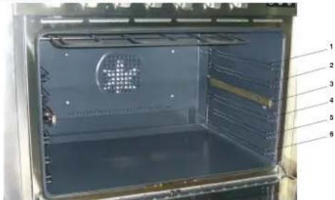
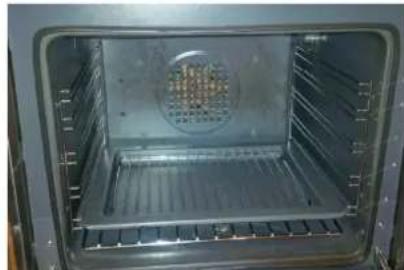
The oven shelf support consists of 5/6 positions. Always remember to position the racks before warming up the oven, and remove all the shelves and roasting pan before cleaning operations.
The slide runners can be positioned in any of the 6 rails
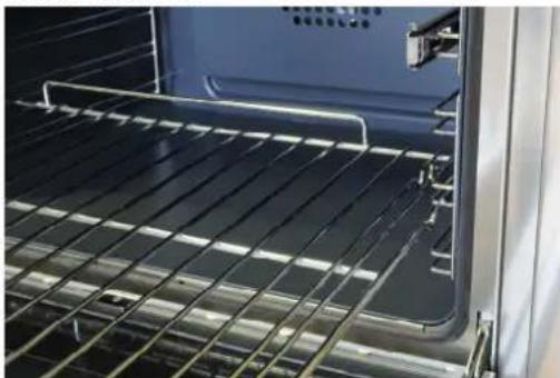
How to correctly place the oven shelves and roasting pan
Oven 76/90cm
Oven 60cm.
natural_image
Interior view of an oven with metal grating and a perforated vent (no text or symbols visible)Oven 60/76cm.
natural_image
Interior view of an oven with metal grating and ventilation duct (no text or symbols visible)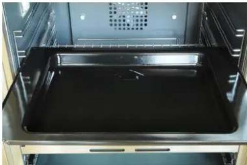
natural_image
Interior view of an oven with a black tray and ventilation grille (no text or symbols visible)Oven 90cm.
natural_image
Interior view of an oven with metal grating and a blue tray (no visible text or symbols)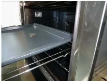
natural_image
Interior view of an oven with a tray and metal door (no visible text or symbols)The retractable slide runners can operate on shelf positions 2 to 6. The wire shelves can be inserted at any shelf position, or on the retractable slide runner.
The roasting pan can be inserted on shelf positions 1, 2, 3, 4 and 5. It can be used with the retractable slide runners for shelf position 6, but cannot be used with the slide runners for shelf position 4.
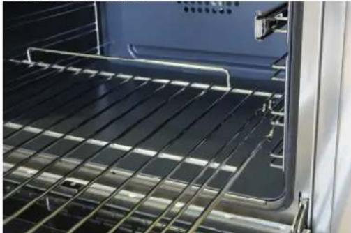
When inserting the wire shelf, the riser should be positioned upwards at the rear of the oven. The grooves at the sides of the shelves, toward the rear provide an anti-slide stability for the oven shelves when extended.
The retractable slide runners can be inserted on any shelf position by clipping or unclipping them between the upper and lower rail of each shelf position
F - Electronic Programmer Operation
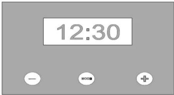
The 24 hour clock allows the setting of automatic cooking options up to 24 hours in advance.
1 - Minus Time Button
2 Mode (Countdown Timer with Alarm, Cooking duration, End Time)
3 + Plus Time Button

IMPORTANT – NOTE FOR NEW INSTALLATION AND FIRST OPERATION
Setting the time on the 24 hour clock
1- The clock will require setting when you first turn on the power (or following a power failure).
2- At power on, the relay contact is opened. The display and AUTO symbol flashes and time of day starts from 0:00.
3- Press PLUS and MINUS button simultaneously for minimum 3 seconds. The AUTO symbol goes out, POT symbol goes on, and the DOT is flashing. With the PLUS button the time will advance slowly, and then speed up. If you over-shoot the desired time, use the MINUS button).
4- Press the MODE button twice to display the time of day. The oven will be in manual cooking mode, with POT symbol [1] displayed.
5- The oven is now ready for use and to accept the selected cooking functions.
Setting the Timer
6- The timer can be set for countdown up to 24 hours and for automatic cooking modes up to 10 hours and will countdown to zero. When zero is reached the alarm will sound.
7- To set the countdown timer
a. Press the MODE button for minimum 3 seconds.
b. The BELL symbol is flashing and the display shows 0:00.
c. Using the PLUS button advance the timer to the desired time.
8- Once the countdown timer is set, the normal time of day will return to the display within 7 seconds. If you wish to check how much time remains on the countdown, press the MODE button for 3 seconds. The remaining time will be displayed. After 7 seconds the normal time will return to the display.
9- A digital alarm will sound when time is reached. To silence the alarm press the MODE button for minimum 4 seconds.
Adjusting the tone of the electronic timer alarm.
THE TONE
There are 3 different tones from which you can select. To change the tone you press the “+” and “-” simultaneously, then press the Mode button once, ton will be displayed. Pressing the “-” button while ton is in the display, will change the tone to the desired setting, then press the mode button once. The electronic timer will store in its memory the last tone activated.
Manual cooking
Once the time of day is set the POT symbol will be displayed. The oven is now in manual operation mode ready for you to select the desired cooking function and temperature.
Automatic cooking modes – Based on setting the duration "DUR"
1 Set cooking function and temperature to the desired position.
2 For example: If you wish to cook for 45 minutes, press the MODE button minimum for 4 seconds. Press the MODE button again. The AUTO symbol is flashing and the display shows "dur". The display automatically switches over between "dur" display and 0:00. During this time you can set the duration time of 45 minutes by pressing the PLUS button (use MINUS button should you over-shoot the required time). Release and the display will return to the normal time of day after 7 seconds. The AUTO symbol will also appear indicating that you have set the automatic cooking function.
3 The oven will operate for 45 minutes only, turn off automatically and the alarm will sound. The AUTO symbol is flashing and the POT symbol will disappear. The alarm will turn off after pressing the MODE button. If you hold the MODE button down longer than 4 seconds the oven will return to the normal cooking mode.
4 If further cooking is required, either leave on manual or repeat the above setting sequence.
Note: If you have not turned the cooking function and temperature setting off, your oven will now continue to operate manually. The AUTO symbol will disappear and the POT symbol will reappear.
Automatic cooking modes – Based on setting a cook end time
1 Set the function and thermostat control to the desired position.
2 For example: If you would like the oven to turn off at 6.00pm, press the MODE button minimum for 4 seconds. Display shows 00:00 with BELL flashing. Press the MODE button two times again. The AUTO symbol is flashing and the display shows "End". The display automatically switches over between "End" and time of day. During this time you can set the cooking stop time to 6.00pm, i.e.18:00 on the 24 hour clock, by pressing the PLUS button (use MINUS button should you over-shoot the required time). Release and the display will return to the normal time of day after 7 seconds. The AUTO symbol will also appear indicating that you have set the automatic cooking function.
3 The oven will continue to cook until 18:00 (6.00pm) and then switch off and the alarm will sound. The AUTO symbol is flashing and the POT symbol will disappear. The alarm will turn off after pressing the MODE button.
4 If you hold the MODE button pressed longer then 4 seconds the oven will return to the normal cooking mode.
5 If further cooking is required, either leave on manual or repeat the above setting sequence.
Note: If you have not turned the cooking function and temperature setting off, your oven will now continue to operate manually. The AUTO symbol will disappear and the POT symbol will reappear.
CANCELING AUTOMATIC SETTINGS
To cancel a program:
Press plus and minus button simultaneously for minimum 3 seconds.
Fully automatic – (Start Later – Stop Later)
Your oven may be programmed to start, cook for the desired time and turn off automatically. This function is particularly useful in the preparation of the evening meal, should you be out during the day, it will be ready on your return home. For example, if your cooking time is 45 minutes and you want the cooking to finish at 6.00 p.m.
1 Press the MODE button minimum for 4 seconds, display shows 00:00. Press the MODE button again, display shows DUR. Set the cooking duration time for say 45 minutes using the PLUS or MINUS button.
2 Press the MODE button again, display shows END. Set the stop cooking time to 6.00pm (18:00hrs). Release and the display will return to the normal time of day after 7 seconds. The AUTO symbol will be displayed.
3 Using the above settings, the oven is now programmed automatically to commence cooking 45 minutes prior to 6.00 pm (18:00hrs). The AUTO symbol and the POT symbol will be displayed. Then automatically turn off.
When cooking is complete the AUTO symbol is flashing and the POT symbol will disappear and the alarm will sound. The alarm will turn off after pressing the MODE button.
4 If you hold the MODE button longer then 4 seconds the oven will return to the normal cooking mode.

NOTE:
On oven start up or possibly at other times, due to electricity supply deviations – the set program may freeze on a function – if this occurs we recommend that, after checking other solutions without success, it is recommended that power supply be disconnected to the appliance and allow it to be in this position for 5 minutes before reconnecting. This may clear the frozen position allowing you to reset the clock/timer for normal operation.
Cooling Fan
The oven is provided with a cooling fan motor to reduce the heat around the oven. The fan motor is controlled by a sensor, which will start when the oven is switched on and stop working when the temperature is reduced accordingly. This safeguards both the range and the adjoining cupboards from the possibility of temperature damage.
Safety Thermostat
Your range is fitted with an over-temperature sensor that will automatically shut down your oven for a period if it is deemed to be overheating- this sensor is fitted to the rear wall of the oven, inside the outer case – it will only activate in extreme circumstances and is provided as protection to the appliance and the adjoining furnishings. If activated it will shut down the appliance for a short time and will automatically reset allowing normal operation – you should consult your service technician if the problem re-occurs.
G - Gas Cooktop Control Panel
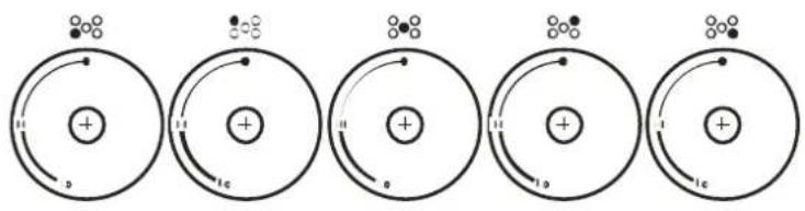
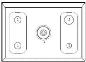
Gas cooktop 76/90cm.
natural_image
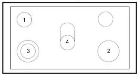
Simple diagram of a rectangular panel with three labeled buttons and a central circular element (no text or symbols)1= semirapid burner 2= rapid burner 3= auxiliary burner 4= wok burner
Technical Characteristic table
| BURNERS | CAS | NORMAL PHILSSURE NETAR | INJECTOR DIMETER 1/100 mm | TAP BY PASS DIMETER 1/100 mm | NORMAL FLAT INPUT MAX (RUTUM) | |
| N° | DESCRIPTION | |||||
| 1 | SEM RAPD | PROPANE NATURAL | 2810 | 72115 | 25REG. | 8,0009,000 |
| 2 | RAPID | PROPANE NATURAL | 2810 | 90155 | 46REG. | 11,30011,500 |
| 3 | AUXILIARY | PROPANE NATURAL | 2810 | 9590 | 25REG. | 5,0005,000 |
| 4 | WOK | PROPANE NATURAL | 2810 | 115200 | 65REG. | 17,50015,600 |
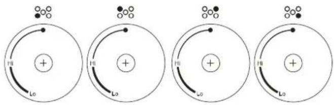
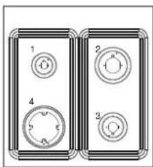
Gas cooktop 60cm.
H - Gas Cooktop Functions
Automatic start-up with valves
Turn the corresponding knob anticlockwise up to the maximum position and press the knob. Once the burner has been started up, keep the knob pressed for about 6 seconds.
Using the burners
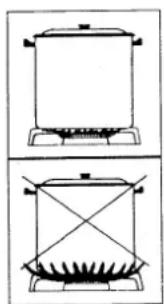
In order to obtain the maximum yield without wasting gas, it is important that the diameter of the pot is suitable for the burner potential (see the following table and fig.1). This is to avoid the flame extremities being larger than the base of the pot. All of the operating positions must be chosen between the high and the low settings, never between the high position and the closing point. The gas supply can be interrupted by turning the knob clockwise up to the off position.
NOTE:
When the equipment is switched off, always check that the knobs are in the off position.
NOTE:
If there is no power supply, it is possible to light the burners with matches, setting the knob to the high setting.
NOTE:
If the flame should blow out accidentally, the safety valve will automatically stop the gas supply, after 20 - 30 seconds. To restore operation, turn the knob to the off position.

WARNING:
-Do not use sprays near the appliance in operation.
-Do not place unstable pots on the burner to prevent them from tipping or overflowing.
-Always turn gas off if moving a pot away from the appliance.
-While cooking with fat or oil, pay the utmost attention as these substances can catch fire when overheated.
I - Ceramic Cooktop Control Panel
Ceramic Cooktop Controls 60/76cm.
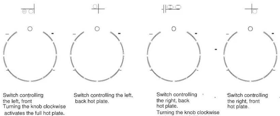
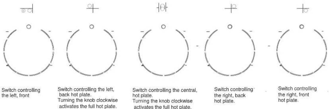
Turning the knob clockwise activates the full hot plate.
Ceramic Cooktop Controls 90cm.
90cm. range
-
Hi-lite heating element
145mm
1200W -
Hi-Lite heating element
60/76cm. range

12/2100mm
750/2200W
2. Hi-Lite heating element
180mm
1800W
4. Hi-Lite heating element
12/2100mm
1400/2200W
To operate Single (inner zone) and separate Dual (inner + outer zone) follow this procedure:
NOTE: On dual zone elements setting 12 has 2 positions.
Single Inner Zone - rotate control knob in clockwise direction selecting power from 1 through 12. The inner zone only will operate.
Inner + Outer Zone = Full Power - rotate control knob clockwise from 1 to 12 as above, then through position 2 - a click will sound (do not Rotate control knob all the way to OFF position as this will damage the control switch and turn power OFF). Then rotate control knob backwards (anticlockwise) selecting power level from 1 to 12 as before. This will activate both Inner and Outer zones concurrently for maximum power.
To deactivate (turn off) Inner Zone or Inner + Outer Zone the control knob must be returned to the OFF position.
Important Note:
DO NOT TURN CONTROL KNOB ANTICLOCKWISE FROM OFF POSITION AS THIS WILL DAMAGE THE CONTROL MECHANISM - OPERATE SINGLE AND DUAL ZONES STRICTLY ACCORDING TO THE INSTRUCTIONS AS ABOVE.
L - Ceramic Cooktop Functions

WARNING
If the surface is cracked, switch off the appliance to avoid the possibility of electric shock, for cooktop surfaces of ceramic glass or similar material which protect live parts.
During use the appliances become hot. Care should be taken to avoid touching heating elements of cooktops and inside the oven. Accessible parts may become hot during use. Young children should be kept away.
All operations relative to installation and electric connection should be carried out by a qualified technician in accordance with the instructions and with local regulations.
The specific instructions are described in the booklet section for the installer, Section A.
NOTE:
- Use only cookware with a sufficiently thick base, equal to or not much larger than the zone selected (fig.1)
- To avoid scratching the ceramic glass top, the cookware should not have a rough base
- Do not switch the electric zone on without the cookware over the zone.
- Do not cook any food directly on the hot area. Avoid overflows of liquid and should they occur clean away promptly.
- The appliance is not intended to be operated by means of external timer or separated remote-control system.
- Turn off the zone a few minutes before the required time, allowing the residual heat from the zone to finish the cooking.
The pilot light on the control panel is switched ON when at least one element is on. The residual heat indicator on the cooktop will light up when the temperature in any area is higher than 50° C.
Cleaning
Remove heavy grease or spills carefully from the cooking surface with the ceramic glass scraper. Then clean the heating area thoroughly with a paper towel and ceramic cleaning products for the correct care of your appliance. Never use abrasive sponge or irritating chemical detergents such as oven spray or spot removers.
Regular cleaning can be achieved with a damp cloth. Dishwashing liquid and vinegar can also be used.
natural_image
Two identical line drawings of a cooking pot on a stove, showing heating and cooling cycles (no text or symbols)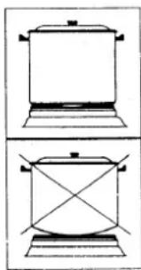
natural_image
Two simple line drawings of a cooking pot with handles and a cross-shaped base, no text or symbols present.FIG-.1
M - Oven Functions & Control Panel
Control Panel:
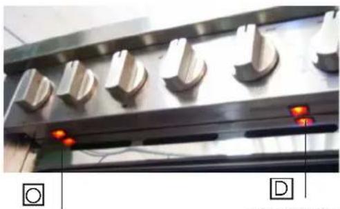
Warming drawer & continuous warm function of main oven 76cm. range
natural_image
Close-up of a metallic industrial control panel with multiple switches and red indicator lights (no visible text or symbols)This switch is controlling the warming element in the bottom oven element (200 watt)
This switch is controlling the warming element in the drawer (200 watt)
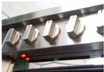
Warming drawer 90cm. range
natural_image
Close-up of metallic mechanical components with four rounded features and a red LED indicator light (no visible text or symbols)This switch is controlling the warming element in the drawer (200 watt)

The warming drawer and warming element of the main oven heats continuously until it reaches 75 Degrees C and this temperature will be maintained throughout the warming process as required

NOTE: The warming elements needs to be switched off manually
During use the appliances become hot. Care should be taken to avoid touching heating elements of cooktops and inside the oven. Accessible parts may become hot during use. Young children should be kept away.
Cooking modes and Instructions

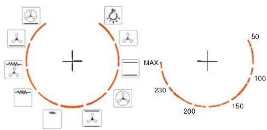
NOTE: Cooking functions will vary from model to model – following is a description of the functions that are available and some or all of these functions be included on the product you have purchased.
The following table summarizes the operating parameters of each cooking mode of the oven.
| Oven function Grill element Top element Bottom element Fan element Light Fan motor | ||||||
| Light X | ||||||
| Defrost/ food warmer | X | X X | ||||
| Conventional X | X | X | ||||
| Convection | X | X X | ||||
| Fan Assist | X | X | X X | |||
| Half Grill X | X | |||||
| Full Grill | X | X | X | |||
| Fan Grill X | X | X X | ||||
| High Bake | X | X X | ||||
| Pizza (Preheat) | X | X | X X | |||
PREHEATING
Preheating the oven is not essential, but you will achieve better results if you do. Some foods, particularly cakes and pastry, are better cooked in a preheated oven. Other foods, for example casseroles, cook just as well when cooked in a non-preheated oven but may need longer cooking times.
For faster preheating select Pizza Mode and the required temperature and once the oven has reached the required level change to the cooking mode/function for the task.
To preheat the oven:
1- Set the mode required for preheating.
2- Set the oven to the desired temperature.
Preheating guide (for 180°C settings)
| Cooking Mode | Preheat Time |
| CONVENTIONAL OVEN | 20-30 MINUTES |
| PIZZA MODE | 15-20 MINUTES |

NOTE:
Any food or other cooking utensils placed in the oven during preheating will affect the preheating time. The preheat time may also vary with installations.
When using an alternative cooking mode for fast preheat, be sure to turn the cooking mode to your required setting before placing food in the oven.
HINT:
To allow for heat loss while placing food into the oven, preheat the oven 10-20°C higher and then reduce the temperature to your required cooking temperature.
Always preheat the oven when cooking multiple dishes at the same time.
Roasting guide. These cooking charts are intended as a guide only. Temperature, cooking mode and cooking times may vary to suit individual tastes.
| Type of Meat Approx. 450 grams = 1lb | Cuts of Meat | Time per lb (allow) | Oven Temperature ° C |
| Beef | Prime Rib, rolled sirloin bolar blade, Top Loin, New York Strip Sirloin | 30 minutes per 1lb20 minutes per 1lb | 1800 - 2000 1800 - 2000 |
| Veal | Shoulder or leg (with bone or rolled) | 20-25 minutes per 1lb | 1800 - 2000 |
| Lamb | Leg, shoulder (loin or rolled) | 20-25 minutes per 1lb | 1800 - 2000 |
| Pork Leg loin | 45 minutes per 1lb 220 | 0-2300 / 1800-2000 |
Pork leg should be cooked at a higher temperature for the first 15-25 minutes then reduced to lower temperature for remaining cooking time.
| Type of Poultry Size of Meat Time per lb | Oven Temperature 0 C | |
| Chicken Whole or pieces 30 minutes per lb. 180 | 0 -200 0 | |
| Duck 3lbs – 4.1lbs | 30 minutes per lb.+ 35 minutes extra | 180 0 -200 0 |
| Turkey 5.4lbs – 21lbs | 40-50 minutes per lb.+ 35 minutes extra | 180 0 -200 0 |
Turkey should be well basted and turned during cooking
| Type of Fish Cuts | of Fish Time per lb | Oven Temperature 0C | |
| Fish Whole or | fillets 10 minutes per lb. | 170-190 | 0C |
In Conventional Oven mode, fish should be covered for the first 3/4 of the cooking time to help retain moisture.
Baking guide. These cooking charts are intended as a guide only. Temperature and cooking times may vary to suit individual tastes.
| Oven Temperature °C | General Times | Foods Suitable |
| 1300 – under Very slow | Small meringues, pavlova, custard, reheating | |
| 1300 - 1500 | Slow | Rich fruit cake, light fruit cake |
| 1500 - 1800 | Moderate | Casseroles, deep butter cake |
| 1800 - 2000 Moderately hot | Shallow butter cakes, sponges, biscuits, meat loaf, baked fish |
| 2000 - 2300 Hot Swiss roll, patty cakes, rock cakes, short crust pastry | |
| 2300 – and over Very Hot Scones, Choux pastry | |

DEFROST
All foods may be defrosted using the Fan Forced Convection mode. It is important to note that this function activates the fan motor and the light only, but it is possible to adjust the temp between 40° C to 60° C after the program starts.
As a general guide, the defrosting time for meat is approximately 15-20 minutes per lb.

VENTIONAL OVEN
In this traditional mode, oven heat is provided from the top and lower oven compartment and is most suitable when cooking on a single shelf. For best results, arrange the shelves so the top of the food is near the centre of the oven.
If cooking on more than one shelf, always preheat the oven and position the pans to allow as much free circulation of heat as possible.
Depending on the food, you may need to rearrange the tray position during cooking.
1- Adjust oven shelves to desired position/s.
2- Select Conventional Oven mode.
3- Set the oven to the desired temperature.
4- When cooking is complete turn the oven off.
HINT:
If water is used in your cooking (such as water placed in a baking dish) the water will evaporate in the oven in the form of steam. The level of condensation will be reduced when cooking in fan oven mode where excess moisture is circulated and evaporates during the cooking cycle.

NOTE: Stand clear of the oven when opening the door as steam may escape rapidly.

ASSIST
This style of cooking provides traditional cooking heating from top and bottom elements with the assistance of a circulation fan to ensure fast even results. This mode is most suitable for delicate cooking such as cakes, pastries, gateaux, biscuits and yeast dough. Best results when thermostat is set to 150-180 degrees – depending on rec

FAN FORCED CONVECTION – most commonly used function
In this mode the oven fan circulates heat from behind the fan cover to give a more even temperature throughout the oven. The even heat provides similar cooking results for each portion of food. Although temperatures for cooking foods in this type of oven are generally the same as required by a conventional oven, when cooking foods that require lengthy cooking cycles a fan forced oven normally cooks more quickly, saving time and energy.
Always place the food as near to the centre of the oven as possible. If cooking on more than one level, arrange the pan positions to allow for free circulation of heat.
1- Adjust oven shelves to desired position/s.
2- Select FAN OVEN mode.
3- Set the oven to the desired temperature.
4- When the cooking is complete turn the oven off.
HINT:
Always preheat the oven when cooking on multiple shelves at the same time.
Depending on the food, you may need to rearrange the tray positions during cooking.

HALF GRILL FULL GRILL

This mode of cooking uses infrared heat from the top of the oven to cook foods to your requirements. Half grill engages only the inner band of the top element and is suitable for smaller volumes and consequently has a lower energy usage.
This method of grilling in the oven is recommended for short duration (5 minutes or less) grilling only, which is ideal for toasting (see note below). Foods with higher fat content or foods, which require more than 5 minutes grilling time, should be grilled using the FAN GRILL mode.
When in GRILL mode the oven door should be closed. If the door is not closed, over time discoloration to the control panel may occur.
1- Commence grilling from a cold oven whenever possible.
2- Place food on grill rack and pan supplied.
3- Position the shelf to your preference.
4- Select GRILL mode and, turn to your desired heat setting.
5- When cooking is complete turn the oven off.

The grill element is controlled by the oven thermostat. Once the temperature in the oven has reached the selected temperature the element will switch off, and then on again, when more heat is required.

NOTE: The temperature setting in FULL & HALF GRILL mode must not exceed 200°C.

NOTE: Door must be closed in Fan Grill Mode
Fan grilling is a combination of direct heat and circulated hot air which gives the appearance and flavor similar to rotisserie cooking which is ideal for single level roasts. Direct infrared heat from the grill element is circulated by the fan to cook the food, which should be positioned as near to the centre of the oven as possible.
For best cooking results, it is recommended that food be turned once only.
1- Oven door must be closed in Fan grill mode.
2- Place food on grill rack and pan supplied (ensure grill rack is inverted to the high position to allow best circulation of air) as close to the centre of the oven as possible.
3- Select FAN GRILL / Pr07 mode.
4- Set the oven to the desired temperature. (See note below and refer to FAN GRILL temperature guide).
5- When cooking is complete turn the oven off.

NOTE:
Large grill pans or roasting dishes can restrict the circulation of air in the oven. To prevent moisture condensing in the cooler lower sections of the oven, preheat the oven for approximately 10 minutes, using CONVENTIONAL OVEN or HIGH BAKE modes, prior to fan grilling.

NOTE: The temperature setting in FAN GRILL mode must not exceed 200°C.
Fan grill guide
These cooking charts are intended as a guide only. Temperatures and cooking times may vary to suit individual tastes.
| Type of meat/poultry/fish | Oven Temperature °C | Approximate Cooking Time |
| Chicken – whole | 1750 - 1850 | 30 minutes per lb |
| Pieces | 1850 - 1950 | 15-20 minutes |
| Lamb - loin/rack | 1750 - 1850 | 25 minutes per lb |
| Chops - medium/rare | 1750 - 1850 | 10-12 minutes |
| Chops – medium | 1750 - 1850 | 14-16 minutes |
| Beef- Steak – rare | 1750 - 1850 | 6-8 minutes |
| Steak – medium | 1750 - 1850 | 8-12 minutes |
| Steak – well done | 1750 - 1850 | 12-15 minutes |
| Pork Chops – medium/rare | 1900 - 2000 | 6-10 minutes |
| Chops - medium | 1750 - 1850 | 10-12 minutes |
| Chops – well done | 1750 - 1850 | 12-15 minutes |
| Sausages- thin | 1750 - 1850 | 8-10 minutes |
| thick | 1750 - 1850 | 12-14 minutes |
| Fish fillets | 1750 - 1850 | 10-14 minutes |
| Sliced vegetables | 1800 - 1900 | 20-30 minutes |
| Tomato halves | 1900 - 2000 | 6-8 minutes |
| Crumb Based dishes | 1750 - 1850 | 20-30 minutes |
| Pasta dishes | 1750 - 1850 | 20-30 minutes |

The HIGH BAKE mode uses the oven fan to circulate air with heat from the lower oven element. Quick and consistent heat is evenly distributed throughout the oven.
The results are quick, not unlike a microwave oven. With the circulation of heat, foods cooked with high bake mode retain a crisp, dry texture on the outside especially pizza, pastry and other foods where you want the base to be well cooked. HIGH BAKE is also excellent for re-heating.
1- Adjust oven shelves to desired position/s.
2- Select HIGH BAKE mode.
3- Set the oven to the desired temperature.
4- When cooking is complete turn the oven off.

PIZZA
This function is excellent as the fastest setting to preheat the oven, engaging maximum power to heat the oven to a selected temperature before selecting an appropriate function and temperature for a task.
In this position the fan and the fan element, together with the bottom oven element, are engaged simultaneously. This is used for food that requires a concentration of cooking to the base, and allows the top to gently cook at the same time.
For best results for pizza and similar items we recommend this function.
N - Cleaning and Maintenance
1. Cleaning and maintenance
Proper cleaning and care of your appliance is essential to maintain its appearance and durability.

NOTE:
People with sensitivity to cleaning chemicals must take the necessary precautions. It is recommended that protective gloves be worn while cleaning the appliance. Routine cleaning of the appliance should only be performed when the appliance is at room temperature.
Do not use any acid or caustic cleaners, abrasive powders or scourers on the interior or exterior of the appliance. Substances or items with these properties may discolor or damage the finishes of your appliance. If any abrasive, acidic or caustic substance or cleaning agent should come into contact with the appliance, rinse off immediately with water, taking special care to avoid injury if surfaces are hot.
When using the appliance, it may be soiled by food spills and spatters or foreign items such as plastics accidentally coming into contact with warm or hot surfaces. Foods which contain acidic substances or sugar can discolor or damage enamel finishes.
The enamel interior of the oven is a hard durable finish which is resistant to wear and discoloration. However, to maintain the appearance and durability of the finish any spills must be wiped off as soon as it is safe to do so. Once cool, the affected area should be thoroughly cleaned and rinsed using non-abrasive, mild cleaning detergents and water.
2. Care for stainless steel
No metal is indestructible and certain procedures should be followed to maintain the finish and durability of stainless steel.
Never leave stainless steel items unwashed. The surface responds best to gentle cleaning methods, scouring materials and harsh abrasives should not be used. Frequent washing with water (preferably hot) is the recommended treatment, followed by rinsing with fresh clean water and wiping dry with a soft cloth or paper towel.
A little soap or detergent may be added to the washing water but too much can produce a cloudy film over the appliance. Use of steel wool is not recommended but stainless steel wool (a fine mesh pad) is an excellent cleaning aid. Oil or grease in the washing water can leave a rainbow film when it dries. It can easily be removed by simply using polishing and cleaning methods described previously. Thoroughly rinsing with clean water is the real secret and it is surprising how easily stainless steel can be kept sparkling clean by using the above simple method.
Never leave stainless steel to dry by itself.
3. Only place cookware on oven shelves.
Other surfaces such as trims are not totally resistant to hard materials or direct heat and may be permanently damaged by such use.
Recommended cleaners
Mild detergents and warm water together with a clean, soft, non-abrasive cloth achieve good results for normal cleaning. Diluted washes with ammonia and water should rinse away any adhesive residue or gummy deposits on the appliance surfaces. Eucalyptus oil (small amounts) is also good for removing adhesive residue. Alcohol based products (eg: methylated spirit, etc.) are not recommended. Brand name cream cleansers and concentrates, without abrasive qualities, can be used in small amounts to break down greasy deposits and dirt.
After cleaning make sure cleaned surfaces are thoroughly rinsed to prevent any risk of baked on cleaner residues and wipe dry with a clean, soft cloth.
Avoid contact with elements, rubber door seals and exterior surfaces.

NOTE:
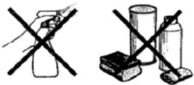
When cleaning stainless steel surfaces Porter&Charles recommends 3M brand or Advance stainless steel cleaner. Other reputable brand cleaners specifically formulated for cleaning stainless steel may also be acceptable. Do not use steel soap pads or abrasive scourers of any kind. The abrasive qualities of these pads will ruin the even brushed finish of the stainless steel and any residual metal fibers may corrode causing a rusty/dull appearance. Metal polishes with abrasive qualities are also not recommended.

WARNING:
Do not use any acid or caustic cleansers or abrasive powders or scourers on the interior or exterior of the appliance.
Routine cleaning
Ensure all controls are in the off position and the appliance is cool before cleaning. When wiping stainless steel surfaces with a brushed finish, wipe in the same direction as the brushing.
To clean the oven interior, fully open or remove the door(s) for better access while cleaning. The shelves and shelf guides can be lifted out for cleaning by removing the relevant thumb screws. The shelves and shelf guides can be washed manually but are also dishwasher safe.
After cleaning make sure all surfaces are thoroughly rinsed and wiped dry with a clean, soft cloth.
Do not use harsh abrasive cleaners or sharp metal scrapers to clean the oven door glass since they can scratch the surface, which may result in shattering of the glass.

DO NOT USE A PORTABLE STEAM CLEANER TO CLEAN THE OVEN.
Self-Cleaning Panels
The range is equipped with 3 panels (sides and rear) to provide a catalytic cleaning process. The catalytic panels are attached to the sides of the oven by removing the rack guides assembly and placing the self cleaning panels against the oven side. The rear panel is attached with screws, ensure that the «rough» side is facing out.
These liners are «self-cleaning» during cooking. If residue remains on them after cooking, remove all shelves, pans and food items, and turn the cooking function selector to Conventional Oven (top and bottom element), and the temperature setting to MAX. 15-20 minutes should be adequate to clean the panels using this method.
How the Self-Cleaning panels work.
The self-cleaning oven panels go through a special enamelling process which ultimately creates a rough surface (this is the side which should face outwards in the oven). Because of the structure of the surface, it is extremely porous and attracts oxygen. When splashes of grease hit this surface it immediately spreads. In this way, immediate oxidization of the grease occurs, and it ultimately disappears while the oven is in general use at standard cooking temperatures. The self-cleaning panels are located on the sides and on the rear of the oven, and are designed to cope with fatty stains very efficiently.
For stains on the bottom of the oven, the usual causes are sugar or starch overflows. The base of the oven should cleaned by using soapy water (see procedure to page 15-16) on a soft clean and newspaper
BEWARE: Never use silicone films (polish or cleaners) on self-cleaning panels - they will be rendered useless.
Similarly, NEVER try to wash with detergent, or use abrasive cleaners on the panels.
Removing Oven Door
The oven door can be easily removed for better access while cleaning. To remove the oven door:
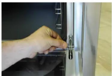
- Open the door fully and fit the supplied pin in the hole on both hinges.
- Raise the door slightly, holding the sides of the door about half way up. Make sure the pin stays in the hole the entire time. Lift the door gently. This should disconnect the hinges from the oven frame.
- Remove the door by continuing to raise it while pulling the door away from the oven. When handling the door be careful not to dislodge the pin from the hole. If the pin does dislodge, the hinge will have to be closed by hand and the pin re-fitted onto the hole before re-fitting into the oven.
To re-fit the oven door:
- Holding the door at an angle to the oven, slide the hinges into the oven frame, making sure that on each side the top curved arm fits into the top slot and the lower arm fits into the bottom slot.
- Make sure the hinges are pushed as far as they will go and the lower arm engages into the plate mounted in the oven frame.
- Open the door fully and ensure the pin fully disengages from the hole. The door can now be opened and closed as normal.
NOTE: Apply gentle downward pressure on the door to help remove the pins.
natural_image
Close-up of a hand inserting a small mechanical component into a white cabinet (no visible text or symbols)Removable Kick Plate
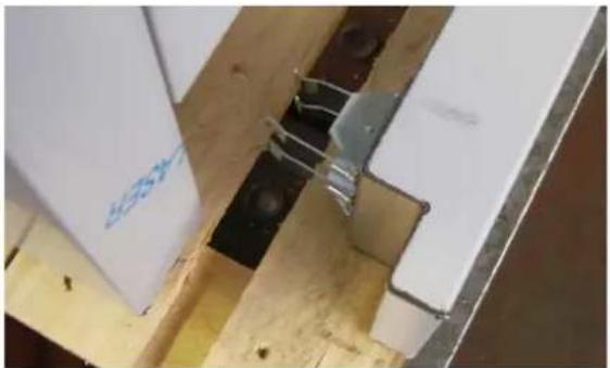
To clean the floor under the range is completed by removing the kick plate. The kick plate is provided with two clips that easily fit on to the legs. You can gain access to the kick plate by extending the warming drawer and reaching under it to gently pull the kick plate forward to release the clips. Refit the kick plate after the cleaning operation by pressing the clips over the legs of the range.
natural_image
Close-up of a mechanical assembly with white panels and metal components, no visible text or symbols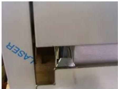
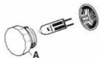
Changing the light bulb 76/90cm. range
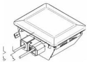
The light bulb is located behind the glass cover and is a push-in type.
WARNING:
ENSURE THE APPLIANCE IS SWITCHED OFF BEFORE REPLACING THE LAMP TO AVOID THE POSSIBILITY OF ELECTRIC SHOCK
To change a light bulb 76/90 cm. range
1- Gently lever out the glass cover.
2- Lift the bulb upwards out of holder.
3- Push in a replacement bulb.
4- Replace the glass cover making sure it fits correctly into place.

NOTE: Recommended globe: Halogen 40W / 230V / 300°C.
natural_image
Technical line drawing of a mechanical assembly with no visible text or symbolsTo change a light globe
1- Gently remove the glass cover
2- Pull the light globe and push in a replacement globe
3- Replace the glass cover making sure it fits correctly into place

NOTE: Recommended globe: Halogen 40W / 230V / 300°C.
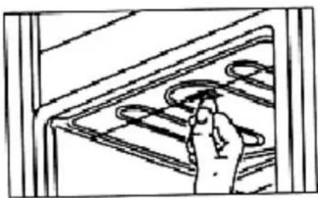
Drop Down Grilling Element
The removal of a single screw at the front of the upper grill element allows the grill to drop down to facilitate the cleaning of the oven ceiling. On completion of cleaning, simply replace the grill element and secure with the screw.
To avoid smoking, use a clean, damp cloth to regularly clean oil and fat splatters from the exposed drop down grilling element.
The fan cover can be lifted out for cleaning separately by removing the retaining screws. The fan blade can also be removed for cleaning if necessary.

NOTE: The fan blade nut has a left-handed thread.
natural_image
Line drawing of a hand adjusting a curved panel with circular elements (no text or symbols)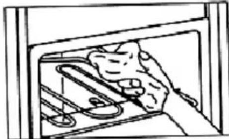
natural_image
Simple line drawing of a person inside a window with pipes and a magnifying glass (no text or symbols)P - Trouble Shooting Guide
| Symptom | Remedy |
| No power supplied to appliance Has the power been disconnected? Check the meter box. Has the main fuse or circuit breaker blown or tripped? | |
| Oven power is on but appliance does not operate | Oven may be set on AUTO (see auto programmed cooking). Ensure clock is set. |
| Oven power is on but there is no heat Oven may be set on AUTO Oven temperature may be set to OFF Mode may be on incorrect selection | |
| Display is flashing, is only part illuminated or is cycling through various displays. | Turn power supply to appliance off, wait 5 minutes and turn power on. Set clock. |
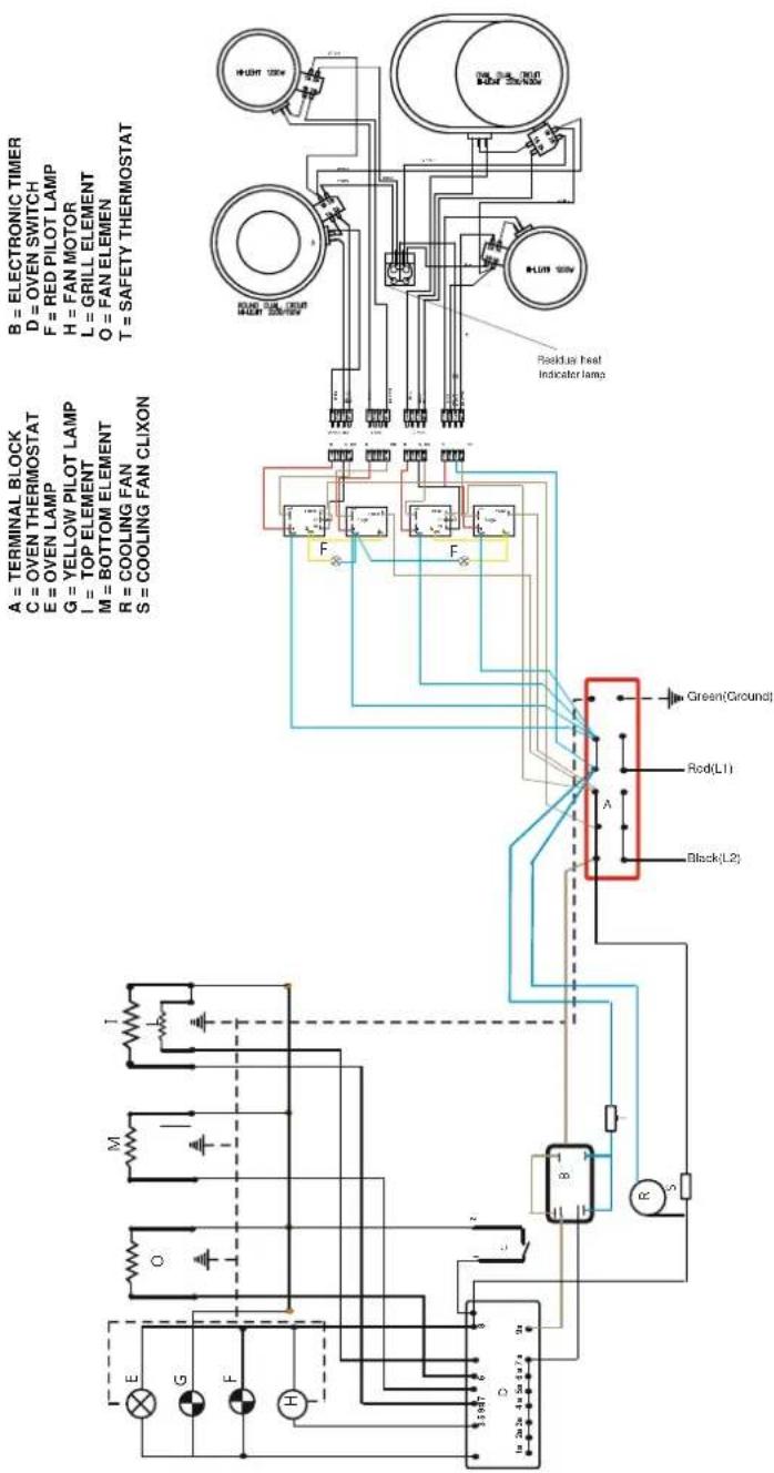
ELECTRICAL WIRING DIAGRAM FREE STANDING COOKER 60 CM. CERAMIC COOKTOP
flowchart
graph TD
    A["Terminal Block"] --> B["Oven Thermostat"]
    B --> C["E = Oven Lamp"]
    C --> D["M = Yellow Pilot Lamp"]
    D --> E["I = Top Element"]
    E --> F["M = Bottom Element"]
    F --> G["R = Cooling Fan"]
    G --> H["S = Cooling Fan CLIXON"]
    I["Electronic Timer"] --> J["D = Oven Switch"]
    J --> K["F = Red PILOT Lamp"]
    K --> L["H = FAN MOTOR"]
    L --> M["L = GRILL ELEMENT"]
    M --> N["O = FAN ELEMENT"]
    N --> O["T = SAFETY THERMOSTAT"]
    P["Indicator lamp"] --> Q["Control Panel"]
    R["Pressure Gauge"] --> S["Ground"]
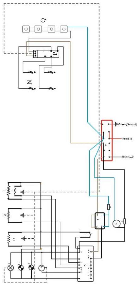
ELECTRICAL WIRING DIAGRAM FREE STANDING COOKER 30" GAS COOKTOP
flowchart
graph TD
    subgraph Control Unit
        A["Component A"] --> B["Relay 1"]
        A --> C["Relay 2"]
        A --> D["Green-Ground"]
        B --> E["Component B"]
        C --> F["Component C"]
        D --> G["Component D"]
        E --> H["Component E"]
        F --> I["Component F"]
        G --> J["Component G"]
        H --> K["Component H"]
        I --> L["Component L"]
        J --> M["Component M"]
        K --> N["Component N"]
        L --> O["Component O"]
        M --> P["Component P"]
        N --> Q["Component Q"]
        O --> R["Component R"]
        P --> S["Component S"]
        Q --> T["Component T"]
    end
    style Control Unit fill:#f9f,stroke:#333
    style A fill:#ccf,stroke:#333
    style B fill:#cfc,stroke:#333
    style C fill:#fcc,stroke:#333
    style D fill:#cff,stroke:#333
    style E fill:#ffc,stroke:#333
    style F fill:#cfc,stroke:#333
    style G fill:#cfc,stroke:#333
    style H fill:#cfc,stroke:#333
    style I fill:#cfc,stroke:#333
    style J fill:#cfc,stroke:#333
    style K fill:#cfc,stroke:#333
    style L fill:#cfc,stroke:#333
    style M fill:#cfc,stroke:#333
    style N fill:#cfc,stroke:#333
    style O fill:#cfc,stroke:#333
    style P fill:#cfc,stroke:#333
    style Q fill:#cfc,stroke:#333
    style R fill:#cfc,stroke:#333
    style S fill:#cfc,stroke:#333
    style T fill:#cfc,stroke:#333
B = ELECTRONIC TIMER
D = OVEN SWITCH
A = TERMINAL BLOCK
C = OVEN THERMOSTAT
E - OVEN LAMP
G - YELLOW PILOT LAMP
= TOPELEMENT
M = BOTTOM ELEMENT
O = FAN ELEMENT
O = SWITCH CHAINE
T - SAFETY THERMOSTAT
FEG60
ELECTRICAL WIRING DIAGRAM FREE STANDING RANGE 30"CERAMIC COOKTOP
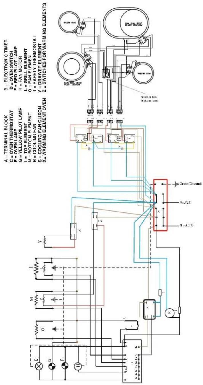
FEC76
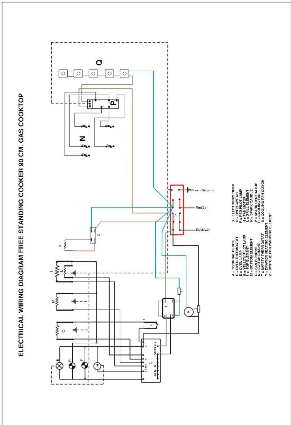
ELECTRICAL WIRING DIAGRAM FREE STANDING COOKER 30" GAS COOKTOP
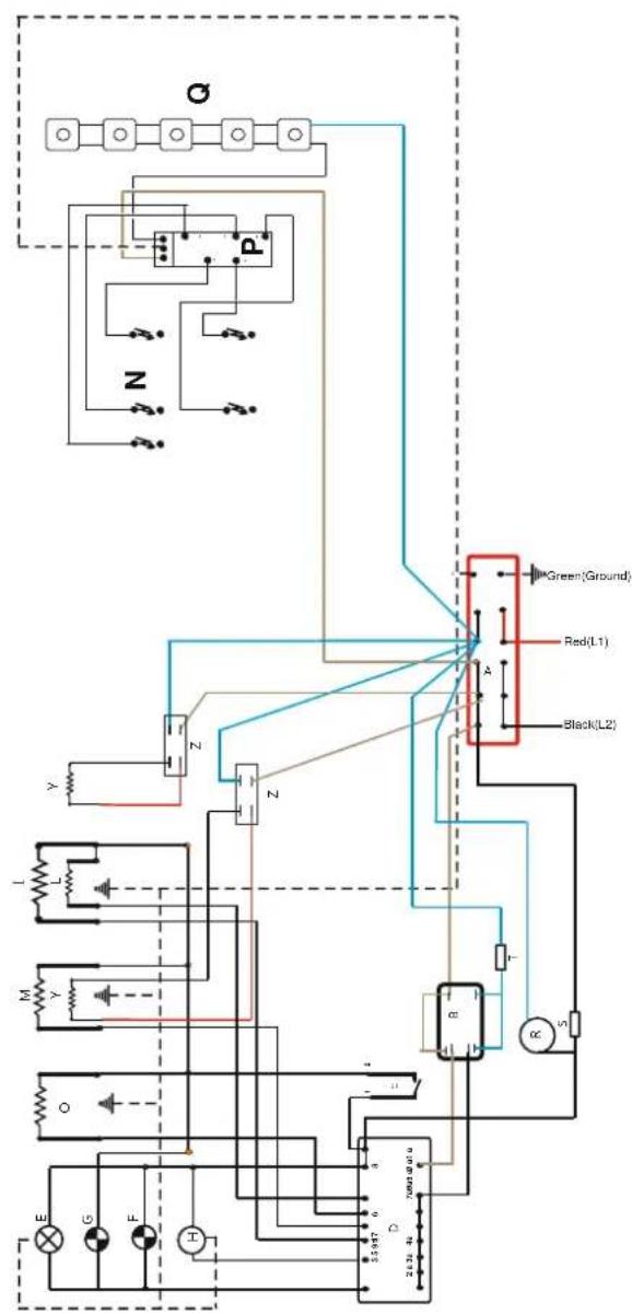
B = ELECTRONIC TIMER
D = OVEN SWITCH
A = TERMINAL BLOCK
C = OVEN THERMOSTAT
E = OVEN LAMP
G = YELLOW PILOT LAMP
I = TOP ELEMENT
M = BOTTOM ELEMENT
P = SPARK GENERATOR
B = COOLING FAN
T = SAFETY THERMOSTAT
FEG60
ELECTRICAL WIRING DIAGRAM FREE STANDING RANGE 30"CERAMIC COOKTOP
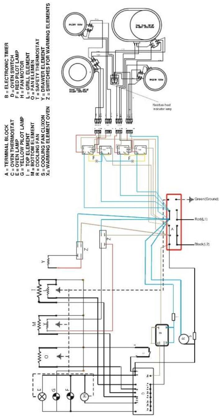
FEC76
ELECTRICAL WIRING DIAGRAM FREE STANDING COOKER 30" GAS COOKTOP
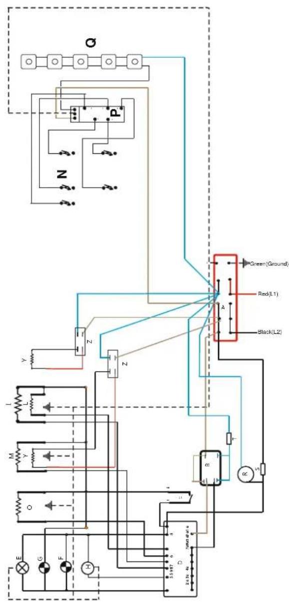
flowchart
graph TD
    A["Component E"] --> B["Resistor O"]
    C["Component G"] --> D["Resistor F"]
    E["Component H"] --> F["Resistor H"]
    G["Component M"] --> H["Resistor Y"]
    I["Component L"] --> J["Resistor L"]
    K["Component Z"] --> L["Resistor Z"]
    M["Component R"] --> N["Resistor R"]
    O["Component S"] --> P["Resistor S"]
    Q["Component N"] --> R["Resistor R"]
    S["Component P"] --> T["Resistor T"]
    U["Component Q"] --> V["Resistor V"]
    W["Input: 2.5±0.476"] --> X["Ground"]
    X --> Y["Node 1"]
    X --> Z["Node 2"]
    X --> AA["Node 3"]
    X --> AB["Node 4"]
    X --> AC["Node 5"]
    X --> AD["Node 6"]
    X --> AE["Node 7"]
    X --> AF["Node 8"]
    X --> AG["Node 9"]
    X --> AH["Node 10"]
    X --> AI["Node 11"]
    X --> AJ["Node 12"]
    X --> AK["Node 13"]
    X --> AL["Node 14"]
    X --> AM["Node 15"]
    X --> AN["Node 16"]
    X --> AO["Node 17"]
    X --> AP["Node 18"]
    X --> AQ["Node 19"]
    X --> AR["Node 20"]
    X --> AS["Node 21"]
    X --> AT["Node 22"]
    X --> AU["Node 23"]
    X --> AV["Node 24"]
    X --> AW["Node 25"]
    X --> AX["Node 26"]
    X --> AY["Node 27"]
    X --> AZ["Node 28"]
    X --> BA["Node 29"]
    X --> BB["Node 30"]
    X --> BC["Node 31"]
    X --> BD["Node 32"]
    X --> BE["Node 33"]
    X --> BF["Node 34"]
    X --> BG["Node 35"]
    X --> BH["Node 36"]
    X --> BI["Node 37"]
    X --> BJ["Node 38"]
    X --> BK["Node 39"]
    X --> BL["Node 40"]
    X --> BM["Node 41"]
    X --> BN["Node 42"]
    X --> BO["Node 43"]
    X --> BP["Node 44"]
    X --> BQ["Node 45"]
    X --> BR["Node 46"]
    X --> BS["Node 47"]
    X --> BT["Node 48"]
    X --> BU["Node 49"]
    X --> BV["Node 50"]
    X --> BW["Node 51"]
    X --> BX["Node 52"]
    X --> BY["Node 53"]
    X --> BZ["Node 54"]
    X --> CA["Node 55"]
B = ELECTRONIC TIMER
D = OVEN SWITCH
F = RED PILOT LAMP
H = FAN MOTOR
L = GRILL ELEMENT
N = SPARK CANDLE
P = SPARK GENERATOR
P = COOLING FAN
T = SAFETY THERMOSTAT S = COOLING FAN CLIXON
Y = DRAWER HEATING ELEMENT/OVEN WARMING HEATING
Z = SWITCHES FOR WARMING ELEMENT
FEG76
ELECTRICAL WIRING DIAGRAM FREE STANDING COOKER 90 CM. CERAMIC COOKTOP
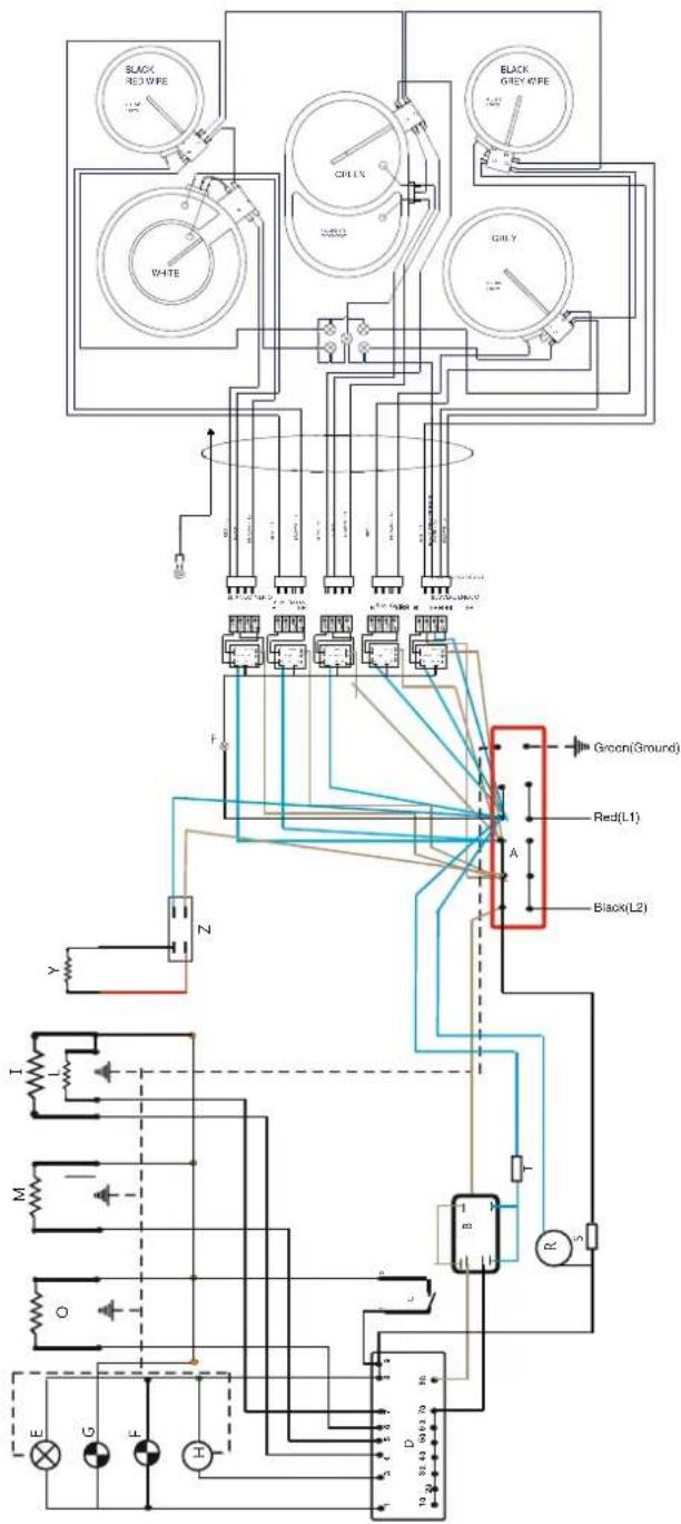
B = ELECTRONIC TIMER
D = OVEN SWITCH
F = RED PILOT LAMP
H = FAN MOTOR
L = GAILLE ELEMENT
O = FAN ELEMEN
T = SAFETY THERMOSTAT
S = COOLING FAN CLIXON Y = DF
Z = SWITCHE FOR WARMING ELEMENT
flowchart
graph TD
    A["Terminal Block"] --> B["O"]
    C["Oven Thermostat"] --> D["M"]
    E["Oven Lamp"] --> F["L"]
    G["Yellow Pilot Lamp"] --> H["R"]
    I["TOP ELEMENT"] --> J["S"]
    K["BOTTOM ELEMENT"] --> L["T"]
    M["FAN MOTOR"] --> N["L"]
    O["FAN ELEMENT"] --> P["P"]
    Q["SWITCH CHAINIE"] --> R["R"]
    S["SAFETY THERMOSTAT"] --> T["S"]
    U["DRAWER HEATING ELEMENT"] --> V["Z"]
    W["COOLING FAN CLIXON"] --> X["S"]
    Y["Green (Ground)"] --> Z["Red(1)"]
    AA["N"] --> AB["P"]
    AC["Q"] --> AD["Ground"]
FEG90
Q - Garantie
- Contents
- A - Installation instructions check and warnings
- WARNING
- IMPORTANT:
- VENTILATION
- CONVERTING TO LPG
- REGULATING THE MINIMUM OUTPUT OF THE COOKTOP BURNERS
- WARNINGS:
- INSTALLATION INSTRUCTIONS
- ATTENTION
- WARNING:
- CONNECTION TO THE GAS SUPPLY: CURRENT INSTALLATION STANDARDS
- B - Range Measurements
- Measurements
- RANGE DIMENSIONS
- ELECTRICAL REQUIREMENTS
- C – Electrical requirements
- Note:
- Voltage supply connection, if unit not supplied with power cord
- D – Using the appliance for the first time
- Power on
- NOTE: Oven will not operate unless the clock is set.
- Burning in
- DO NOT use aluminum foil on the base of ovens
- Initial heat up
- Don't use the appliance as a space heater
- Do not leave children alone
- Wear proper apparel when using the appliance
- Use only dry pot holders
- Oven compartments must never be used for storage
- Do not use water on grease fires
- E - Accessories
- Your appliance should come equipped with the following items.
- How to correctly place the oven shelves and roasting pan
- F - Electronic Programmer Operation
- IMPORTANT – NOTE FOR NEW INSTALLATION AND FIRST OPERATION
- Setting the time on the 24 hour clock
- Setting the Timer
- THE TONE
- Manual cooking
- Automatic cooking modes – Based on setting the duration "DUR"
- Automatic cooking modes – Based on setting a cook end time
- CANCELING AUTOMATIC SETTINGS
- To cancel a program:
- Fully automatic – (Start Later – Stop Later)
- Cooling Fan
- Safety Thermostat
- G - Gas Cooktop Control Panel
- H - Gas Cooktop Functions
- Automatic start-up with valves
- Using the burners
- I - Ceramic Cooktop Control Panel
- L - Ceramic Cooktop Functions
- The specific instructions are described in the booklet section for the installer, Section A.
- Cleaning
- M - Oven Functions & Control Panel
- Cooking modes and Instructions
- PREHEATING
- To preheat the oven:
- HINT:
- DEFROST
- VENTIONAL OVEN
- ASSIST
- FAN FORCED CONVECTION – most commonly used function
- HALF GRILL FULL GRILL
- NOTE: Door must be closed in Fan Grill Mode
- Fan grill guide
- PIZZA
- N - Cleaning and Maintenance
- Cleaning and maintenance
- Care for stainless steel
- Only place cookware on oven shelves.
- Recommended cleaners
- Routine cleaning
- Self-Cleaning Panels
- How the Self-Cleaning panels work.
- Removing Oven Door
- To re-fit the oven door:
- Removable Kick Plate
- To change a light bulb 76/90 cm. range
- To change a light globe
- Drop Down Grilling Element
- P - Trouble Shooting Guide
- Q - Garantie
Brand : Porter & Charles
Model : FEC76B3
Category : Cooker