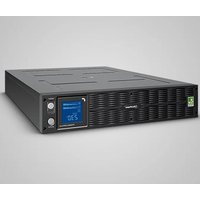
PR3000ELCDRTXL2U - Uninterruptible power supply CyberPower - Free user manual and instructions
Find the device manual for free PR3000ELCDRTXL2U CyberPower in PDF.


| Product Type | Uninterruptible Power Supply (UPS) |
| Brand | CyberPower |
| Model | PR3000ELCDRTXL2U |
| Power (VA/Watts) | 3000 VA / 2400 W |
| Dimensions (cm) | 43,3 x 8,8 x 60 (2U rack) |
| Weight (kg) | 41,8 |
| Input Voltage | 150-300 VAC |
| Input Frequency | 50/60 Hz (auto-detection) |
| Battery Output Voltage | 220 / 230 / 240 VAC ±5% |
| Battery Output Frequency | 50/60 Hz ±0,1 Hz |
| Battery Type | Sealed lead-acid, 12V / 9.0 Ah x 4 |
| Replacement Battery Reference | RBP0040 |
| Output Receptacles | 8 x IEC C13, 1 x IEC C19 |
| Connectivity | USB, RS-232 (x2), RJ11/RJ45, EPO port |
| Management Software | PowerPanel Business Edition |
| Protections | Surge protection, automatic voltage regulation (AVR), input and output circuit breakers |
| LCD Display | Multifunction with icons and messages |
| Special Features | Critical/non-critical outlets, silent mode, GreenPower, optional external battery |
| Maintenance | Recharge battery every 3 months in storage; clean with a dry cloth |
| Safety | Use a grounded outlet; do not open the casing; maintain safety distances |
| Operating Temperature | 0°C to 40°C |
Frequently Asked Questions - PR3000ELCDRTXL2U CyberPower
User questions about PR3000ELCDRTXL2U CyberPower
0 question about this device. Answer the ones you know or ask your own.
Ask a new question about this device
Download the instructions for your Uninterruptible power supply in PDF format for free! Find your manual PR3000ELCDRTXL2U - CyberPower and take your electronic device back in hand. On this page are published all the documents necessary for the use of your device. PR3000ELCDRTXL2U by CyberPower.
USER MANUAL PR3000ELCDRTXL2U CyberPower
Reliability. Quality. Value.
User's Manual
Professional Rack Mount LCD XL Series
PR3000ELCDRTXL2U
IMPORTANT SAFETY INSTRUCTIONS
This manual contains important instructions. Please read and follow all instructions carefully during installation and operation of the unit. Read this manual thoroughly before attempting to unpack, install, or operate the UPS.
CAUTION! The UPS must be connected to a grounded AC power outlet with fuse or circuit breaker protection. DO NOT plug the UPS into an outlet that is not grounded. If you need to power-drain this equipment, turn off and unplug the unit.
CAUTION! The battery can power hazardous components inside the unit, even when the AC input power is disconnected.
CAUTION! The UPS should be near the connected equipment and easily accessible.
CAUTION! To prevent the risk of fire or electric shock, install in a temperature and humidity controlled indoor area, free of conductive contaminants. (Please see specifications for acceptable temperature and humidity range).
CAUTION! To reduce the risk of an electric shock, do not remove the cover, except to service the battery. There are no user serviceable parts inside, except for the battery.
CAUTION! To avoid electrical shock, turn off the unit and unplug it from the AC power source before servicing the battery or installing a computer component.
CAUTION! To reduce the risk of fire, connect the UPS to a circuit with 16 amperes maximum over-current protection in accordance to CE requirement.
CAUTION! The AC outlet where the UPS is connected should be close to the unit and easily accessible.
CAUTION! Please use only VDE-tested, CE-marked mains cable, (e.g. the mains cable of your equipment), to connect the UPS to the AC outlet.
CAUTION! Please use only VDE-tested, CE-marked power cables to connect any equipment to the UPS.
CAUTION! When installing the equipment, ensure that the sum of the leakage current of the UPS and the connected equipment does not exceed 3.5mA.
CAUTION! This is permanently connected equipment and only qualified maintenance personnel may carry out installations.
CAUTION! Do not unplug the unit from AC Power during operation, as this will invalidate the protective ground insulation.
CAUTION! DO NOT USE FOR MEDICAL OR LIFE SUPPORT EQUIPMENT! Under no circumstances this unit should be used for medical applications involving life support equipment and/or patient care.
CAUTION! DO NOT USE WITH OR NEAR AQUARIUMS! To reduce the risk of fire, do not use with or near aquariums. Condensation from the aquarium can come in contact with metal electrical contacts and cause the machine to short out.
DO NOT INSTALL THE UPS WHERE IT WOULD BE EXPOSED TO DIRECT SUNLIGHT OR NEAR A STRONG HEAT SOURCE!
The box should contain the following:
(1) UPS unit x 1; (2) User manual x 1; (3) Phone line x 1; (4) PowerPanel® Business Edition software CD x 1; (5) USB A+B type cable x 1; (6) Rack mount Brackets x 2; (7) Skids x 2; (8) Emergency Power Off Cable (gray) x 1; (9) Serial Interface Cable (DB-9) x 2; (10) Power cord x 4
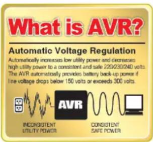
AUTOMATIC VOLTAGE REGULATOR(AVR)
The PR3000ELCDRTXL2U can stabilize the consistent utility power. The utility power may be damaging to important data and hardware, but Automatic Voltage Regulation helps the computer not experience dangerous voltage levels. Automatic Voltage Regulator automatically regulates low or high voltages to keep equipment working at safe AC power levels (220/230/240V) without switching to battery. Your equipment can operate normally even meet the power problems, such as, shout brownouts and blackouts. The unit's powerful sealed lead-acid batteries will provide power only if the incoming voltage drops below 150V or increases above 300V.
INSTALLING YOUR UPS SYSTEM (continued)
SYSTEM BLOCK DIAGRAM
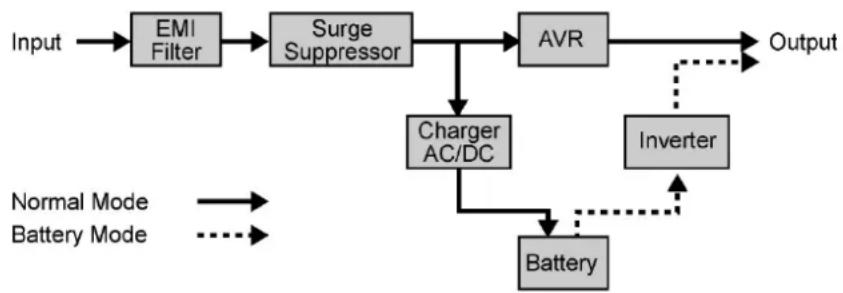
flowchart
graph TD
    A["Input"] --> B["EMI Filter"]
    B --> C["Surge Suppressor"]
    C --> D["AVR"]
    D --> E["Output"]
    D --> F["Charger AC/DC"]
    F --> G["Battery"]
    G --> H["Inverter"]
    H --> E
    style A fill:#f9f,stroke:#333
    style E fill:#ccf,stroke:#333
    note1["Normal Mode\nBattery Mode"] --> A
    note2["Dotted arrow"] --> H
HARDWARE INSTALLATION GUIDE
- Battery charge loss may occur during shipping and storage. For the first time the UPS is used, it's strongly recommended to charge batteries for at least 12 hours is recommended to ensure that the batteries' maximum charge capacity. To recharge the batteries, simply make the UPS plugs into an AC outlet.
- When you use the included software, connect either the serial or the USB cable between the computer and the corresponding port on the UPS. Note: If the USB port is used, the serial port will be disabled. They cannot be used simultaneously. The computer with the PowerPanel® Business Edition S/W connects to the USB port or the Serial port on the UPS. It can control the operating schedule, battery test, outlet, etc. and get information on the UPS status. However, other computers with PowerPanel® Business Edition S/W can only get UPS status information via a LAN connection.
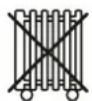
- With the UPS off and unplugged, connect your computer, monitor, and any externally powered data storage device (Hard drive, Tape drive, etc.) into the outlets. DO NOT plug a laser printer, copier, space heater, vacuum, paper shredder or other large electrical device into the UPS. The power demands of these devices will overload and possibly damage the unit.
- To protect a fax, telephone, modem line or network cable, connect the telephone or network cable from the wall jack outlet to the jack marked "IN" of the UPS. Then, connect a telephone cable or network cable from the jack marked "OUT" on the UPS to the modem, computer, telephone, fax machine, or network device.
INSTALLING YOUR UPS SYSTEM (continued)
- Press the power switch to turn the UPS on. The Power-On indicator light will illuminate. If an overload is detected, an audible alarm will sound and the UPS will emit one long beep. In order to reset it, turn the unit off and unplug some equipment from outlets. Make sure your equipment carry a load current within the unit's safe range, (refer to the technical specifications), and then turn the unit on.
- Your UPS is equipped with an auto-charge feature. When the UPS is plugged into an AC outlet, the battery will be automatically charging, even when the unit is switched off!
- To always maintain an optimal battery charge, leave the UPS plugged into an AC outlet at all times.
- Before storing the UPS for an extended period of time, turn the unit OFF. Then cover it and store it with the batteries fully charged. Recharge the batteries every three months or so, to ensure good battery capacity and long battery life; further, this might also prevent damage to the unit from an unlikely battery leakage.
- The unit provides one Primary Serial Port (I), Secondary Serial Port (II), and one USB port, (paired with the Primary Serial Port), to allow connection and communication between the unit and any attached computers. The Primary Serial Port (I) as well as its paired USB port allow for bi-directional communication among the UPS and the primary connected computer running the PowerPanel ^® Business Edition S/W provided. The UPS can control the computer's shutdown in case of an emergency, and at the same time, the computer can monitor the UPS and alter its various programmable parameters. On the other hand, secondary Serial Port II, only allows the UPS to initiate the connected computer's graceful auto-shutdown in case of an emergency.
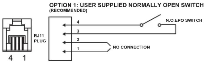
- EPO (Emergency Power Off) Port:
Use the provided gray cable to connect to a special EPO contact switch. Follow the appropriate circuit diagram below to wire the cable to your EPO configuration. The EPO remote switch is a switch installed in an outside area, connected to the unit via an ordinary RJ-11 phone line. In case of an emergency, it can be used to immediately cut-off power from the UPS unit.
OPTION 2: USER SUPPLIED NORMALLY CLOSED SWITCH
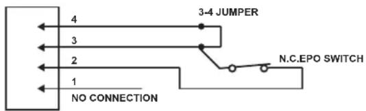
flowchart
graph TD
    A["3-4 JUMPER"] --> B["N.C.EPO SWITCH"]
    C["NO CONNECTION"] --> A
    D["4"] --> A
    E["3"] --> A
    F["2"] --> A
    G["1"] --> A
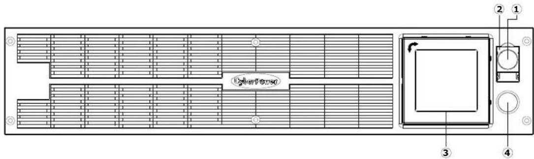
FRONT / REAR PANEL DESCRIPTION
1. Power Switch
Master on/off switch for equipment connected to the UPS.
2. Power On Indicator
Indicate that the AC utility input power's condition is normal and that the UPS outlets are providing power, free of surges and spikes.
3. Multifunction LCD Readout
An LCD that shows various UPS information using icons and messages.
4. LCD Readout Toggle Button
Used to select among a variety of information the LCD can display.
PR3000ELCDRTXL2U
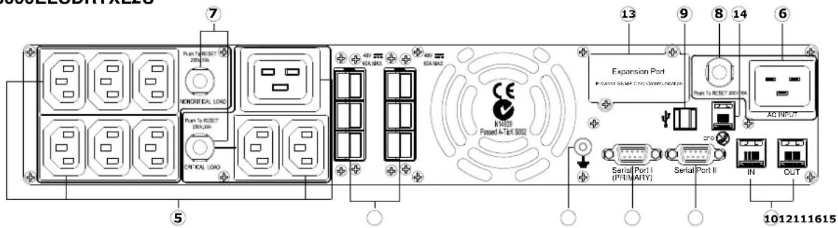
5. Battery Backup, Surge Protected and AVR protected Outlets
This unit provides a total of nine outlets with battery backup and surge protection. They ensure that connected equipment will keep an uninterrupted operation over a period of time, during a power failure.
Critical /Non-critical
It is possible to program the unit in a way so that the outlet block marked as “non-Critical”, (6 ports), will stop the provision of power to connected equipment after a certain period of time, thus making more runtime available for the equipment connected on the outlets marked as “Critical”, (3 ports). In other words, the user can establish runtime priority for certain connected equipment, maximizing its “availability” during a prolonged power outage. This type of control takes place with the use of the provided PowerPanel® Business Edition S/W.
6. AC Inlet
Connect the AC Power cord to a properly wired and grounded outlet.
7. Output Circuit Breaker
The circuit breaker serves to provide output overload and fault protection.
8. Input Circuit Breaker
The circuit breaker serves to provide input overload and fault protection.
9. USB port to PC
This is a connectivity port allowing communication and control among the UPS and the connected computer. You should install on your computer the PowerPanel ^® Business Edition software appropriate to the operating system you are using.
10. Surge Protected Communication Ports - RJ11/RJ45
These ports are being used to protect from various surge-conditions the standard RJ-45/RJ-11 based, (ADSL, LAN, Phone/Modem-Lines), cabling systems.
11. Serial Port I (Primary)
Serial port I allow for bi-directional communication among the UPS and the computer. The UPS can control the computer's shutdown in case of an emergency, and at the same time, the computer can monitor the UPS and alter its various programmable parameters.
12. Serial Port II (Secondary)
Serial Port II allows the UPS to initiate the connected computer's graceful auto-shutdown in case of an emergency.
13. SNMP/HTTP Network slot
Remove the cover panel to install optional SNMP, allowing your UPS be controlled and monitored via a network connection.
14. EPO (Emergency Power Off) Port
Allow for an emergency UPS Power-Off from a remote location.
15. External Battery Pack Connector
Provides a connection for additional CyberPower external battery packs for extended runtime.
16. Ground Stud
Use the Ground Stud to ground the UPS.
5 Copyright © 2015 CyberPower Systems, Inc.
Rackmount Installation
Step 1: Rackmount ear and handle installation
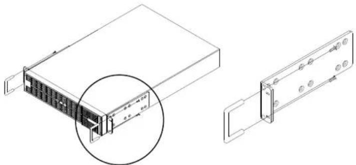
natural_image
Technical line drawing of a server rack with an inset view showing internal components (no text or symbols)Attach the Rackmount Handles to the Rackmount Ears using the provided screws.
Step 2: Rackmount Rail Installation
Each Rackmount Rail (Left and Right) consists of two (2) pieces that must be assembled together before installing into the rack.

natural_image
Technical line drawing of two mechanical components with mounting brackets and internal ribs (no text or symbols)Attach the two Rackmount Ears to the UPS using the provided screws.
Step 3: Adjust rack mount rails to fit your rack
Take the Rackmount Rail inscribed with an "L" (Left) and attach it to the rear bracket of the Rackmount Rail using three (3) of the six (6) Rackmount Rail Screws. Do not fully tighten the Rackmount Rail screws, as the Rackmount Rails will need to be adjusted to fit your rack. Once complete, perform the same steps for assembling the Rackmount Rail inscribed with an "R" (Right).
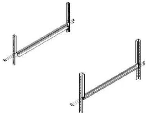
natural_image
Two identical metal structural beams with vertical supports, shown from different angles (no text or symbols)Attach the Rackmount Rails to your rack using fasteners that are designed for your rack system.
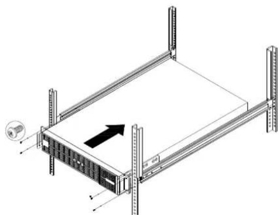
natural_image
Isometric line drawing of a server rack with vertical supports and an arrow indicating direction (no text or symbols)Step 4: Adjust rack mount rails to fit your rack
Slide the UPS on top of the newly installed Rackmount Rails, and secure the UPS to your existing rack system [via the Rackmount Ears] using fasteners that are designed for your rack system.
VERTICAZL/TOWER INSTALLATION
Step 1: Attach Dust Covers
Insert Dust Covers into the Rackmount Ear screw holes that are not being used.
Step 2: Attach the base stands
Simply slide the base stands onto the bottom of the UPS, roughly 8-10" apart.
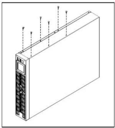
natural_image
Isometric line drawing of a server or rack unit with multiple ports and connectors (no text or symbols)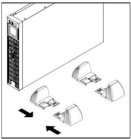
natural_image
Diagram of a server rack with multiple ports and directional arrows indicating movement or assembly (no text or symbols present)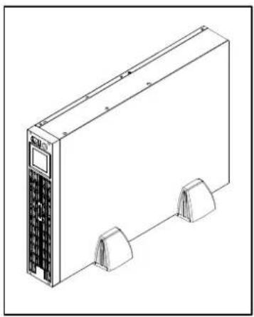
natural_image
Line drawing of a server or electronic device with two ports and a control panel (no text or symbols)Step 3: Rotate the Multifunction LCD Readout
natural_image
Isometric line drawing of a rectangular air conditioner unit with ventilation grilles and a close-up inset showing internal components (no text or symbols)
natural_image
Diagram of a server rack with ventilation slots and a monitor icon, showing rotation arrow (no text or symbols)The LCD is out.
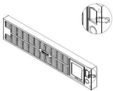
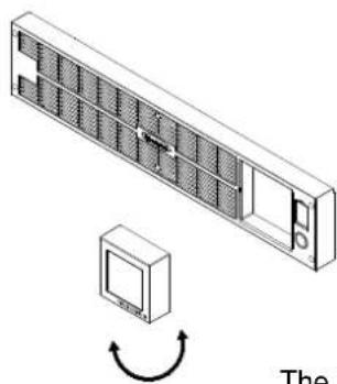
Insert a small straight-slot screwdriver into the notch and gently lift the LCD out. Switch back and forth lifting one side then the other to gently work it out far enough that you can grasp it with your fingers and pull it out.

Push it back in with your fingers.
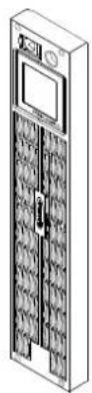

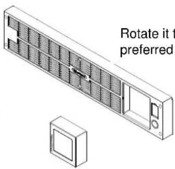
Rotate it to the preferred orientation.
BATTERY REPLACEMENT
Read and follow the IMPORTANT SAFETY INSTRUCTIONS before servicing the batteries:
Servicing the batteries should only be performed by professionals. Please Contact your dealer. Make a note for the replacement battery pack number, (RBP0040), regarding PR3000ELCDRTXL2U.
CAUTION! Use only the specified type of battery: HR9-12FR(BB) for PR3000ELCDRTXL2U. Contact your dealer for replacement batteries.
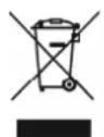
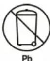
CAUTION! The battery may present the risk of electrical shock. Do not dispose of batteries on fire, since they may explode. Follow all local ordinances regarding the proper disposal of batteries.
CAUTION! Do not open or mutilate the batteries. Released electrolyte is harmful to the skin and eyes and may be toxic.
CAUTION! A battery can present a high risk of short-circuits and electrical shocks.
Take the following precautions before replacing the battery:
- Remove all watches, rings or other metal objects from your hands.
- Only use tools with insulated handles.
- DO NOT lay tools or other metal parts on top of battery or any battery terminals.
- Wear rubber gloves and shoes.
- Determine if the battery is grounded. If so, remove source of ground. CAUTION: CONTACT WITH A GROUNDED BATTERY CAN RESULT IN ELECTRICAL SHOCK! The likelihood of such a shock will be greatly reduced if such grounding is removed during installation and maintenance.
BATTERY REPLACEMENT (continued)
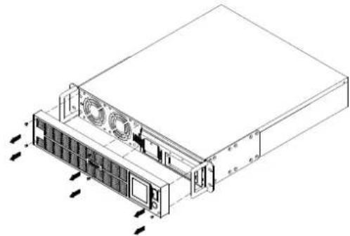
BATTERY REPLACEMENT PROCEDURE:
natural_image
Technical line drawing of a server rack unit with ventilation fans and drive bays (no text or labels)- Remove the front panel on the right side.
natural_image
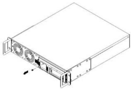
Isometric line drawing of a server rack unit with ventilation fans and drive bays (no text or labels)- Remove the one retaining screw of the cable protection cover.
natural_image
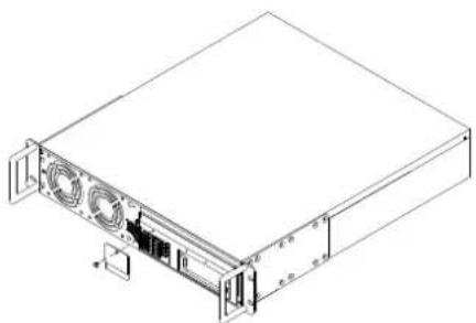
Isometric line drawing of a server rack unit with ventilation fans and drive bays (no text or labels)- Remove the cable protection cover.
natural_image
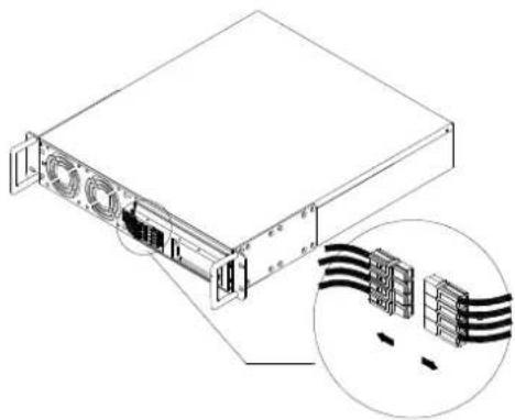
Technical line drawing of a server rack with ventilation slots and an inset showing cable connections (no text or symbols)- Disconnect the black wire and red wire from the battery.
natural_image
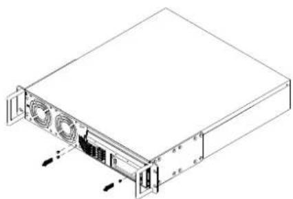
Isometric line drawing of a server rack unit with ventilation fans and drive bays (no text or labels)- Remove the three retaining screws.
natural_image
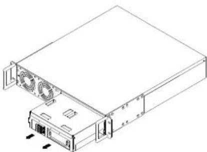
Technical line drawing of a server rack with cooling fans and drive bays (no text or symbols)- Put the new battery packs back into the compartment. Tighten up the screws and replace the cable protection cover and the front panel. Recharge the unit for 12 hours to ensure the UPS performs expected runtime.
REMINDER! The used batteries are hazardous wastes and must be disposed through recycling. Most retailers that sell lead-acid batteries collect used batteries for recycling, as required by the local regulations.
DEFINITION FOR ILLUMINATED LCD INDICATORS
-
Input voltage meter: This meter measures the AC voltage from the wall outlet. The INPUT voltage readout is used to identify the input voltage information. This can be used as a diagnostic tool to identify poor-quality input power. Units are listed in V (Volts). When the UPS connect to any equipment, the AVR can provide a stable 220/230/240V power output. In the event of a complete loss of power, severe brownout, or over voltage, the UPS relies on its internal battery to back up to supply a consistent 220/230/240V output.
-
Output voltage meter: The Output Voltage screen measures, in real time, the AC voltage that the UPS is providing to your connected equipment via the UPS outlets. Units are listed in V (Volts).
-
Estimate run time: The Estimated Runtime Screen displays how many minutes of runtime can be expected of the UPS if it were to experience a power outage. When runtime becomes shorted, the battery capacity will decrease; (battery capacity bar indicator will be falling.) Note: The number displayed may be less than actual runtimes for low loads.
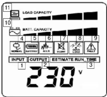
The LCD displays detailed information on the UPS status and current power conditions to alert you to potential power problems before the affect your equipment. Note! All related UPS information is based on that you should turn on the UPS.
-
Normal icon: This icon illuminates when the UPS is working under normal conditions.
-
Battery icon: When there is a severe brownout or blackout, this icon will appear followed by an alarm, (two short beeps), indicating that the UPS is now working using its internal batteries. Once the batteries are run out of power, (over a period of time), a constant alarm will sound. If this happens and main power has not been restored, it is recommended that you save your files and turn off your equipment manually as soon as possible.
- Automatic Voltage Regulation (AVR) icon: This icon will appear when the unit is automatically regulating low or high AC input line voltage conditions, without resulting to the use of battery power.
- Silent mode icon: This icon appearing indicates that the buzzer will not be beeping while in battery operating mode. During Silent mode, the unit's alarm does not sound until the Battery Capacity falls to < 20%.
- Over load icon: This icon will appear followed by an alarm, indicating that an overload condition has been reached. To recover from the overload condition, start unplugging your equipment from the UPS outlets until the icon disappears and the alarm stops.
- Fault icon: When activated indicates a system fault error. Please refer to the troubleshooting table for possible causes and solutions.
- BATT. CAPACITY: BATT. CAPACITY is shown as a bar chart; each segment indicates approximately a 20% of battery capacity.
- LOAD CAPACITY: Load CAPACITY is shown as a bar chart; each segment indicates approximately a 20% of load capacity.
1. General Mode:
a. Press the "Display-Toggle" button to check the status of the UPS status:
| Item Unit | ||
| 1 | Input Voltage V | |
| 2 | Output Voltage V | |
| 3 | Output Frequency Hz | |
| 4 | Load Kw | |
| 5 | Estimate Run Time Min | |
| 6 | Load Capacity % | |
| 7 | Battery Capacity % | |
| 8 | Centigrade °C | |
| 9 | Fahrenheit °F |
b. Press and hold the "Display-Toggle" button for 4 seconds, If the machine is in the Battery Mode with active alarm, it will become silent. If the machine is in the Line Mode, a self-diagnostic test will take place.
c. If the "Display-Toggle" button remains untouched for over 30 seconds, the LCD backlight will turn off automatically.
2. Set-up Mode
Step 1: Hold the "Display-Toggle" button for 10 seconds to enter the UPS Set-Up Mode.
Step 2: By pressing the Display toggle, users can switch between setup functions. Some User Configurable functions are as follows:
a. Delay Time: The time delay between switching from Battery Mode to Line Mode. There are 9 different settings. The default setting is 0 minutes.
b. Battery Pack Numbers: This function provides the estimated UPS runtime using various numbers of battery packs. The default setting is 0.
c. Static Frequency Tolerance: There are 4 settings (1, 2, 4, 6 %), and the default setting is +/-6%. Functional description: The setting may be adjusted to the quality of the electricity in use.
d. Slew rate: Also known as Dynamic Frequency Tolerance. There are 5 different settings (0.25, 0.5, 1, 2, 4 Hz/Sec). The fault value is 4Hz/sec. Functional Description: "Slew Rate" indicates the tolerance of a device in accepting frequency variance. Lower "Slew Rate" results in less tolerance but better protection for the connected load and vice versa.
e. Low Battery Shutdown Voltage: This function will adjust the UPS shutdown point according to the battery's remaining capacity.
These programmable items are sorted by unit as in the following table :
| Items | Unit |
| Delay Time | Min |
| Battery Pack Numbers | A |
| Voltage Mode (220/230/240) | V |
| Static Frequency Tolerance | % |
| Slew Rate | Hz |
| Low Battery Shutdown Voltage | V |
| Firmware Version | None |
11 Copyright © 2015 CyberPower Systems, Inc.
LCD SETUP FUCTIONS
Step 3: Press and hold the display-toggle for 4 seconds. When the icons blink, the value of each item is changed by slightly pressing the toggle.
Step 4: To save the value and return to general mode, press and hold the toggle for 4 seconds.
Note! If the UPS is left idle for over 30 seconds during setup, it will turn off the backlight and return to general mode automatically.
Note! If the user does not want to save the new settings and return to the general mode, there are two methods:
(1) Wait for the backlight to turn off, or,
(2) By pressing and holding the "Display-toggle" key for 10 second.
CYBERPOWER GREENPOWER UPS™ TECHNOLOGY
GreenPower UPS™
CyberPower's GreenPower UPS™ Circuit Design is a solution to this problem "Power Loss." When the Utility Power is operating normally, Green Power UPS™ works in Bypass Mode.
Our GreenPower UPS ^™ design conducts power only through the Relay and still provides normal output voltage. Bypassing the transformer reduces power consumption thereby conserving energy and saving money. When the utility power is abnormal the UPS will operate under Battery or AVR Mode. Under this condition Green Power UPS ^™ and a traditional UPS would operate about the same.

On average utility power operates 88% of the time and the CyberPower GreenPower Technology will work in its money/ energy saving Bypass Mode.
| Model PR3000ELCDRTXL2U | |
| Capacity (VA) 3000 | |
| Capacity (Watts) 2400 | |
| Input | |
| Input connections IEC 320 C20 | |
| Nominal Input Voltage 230Vac | |
| Input Voltage Range 150Vac - 300Vac | |
| Input Frequency Range | 50/60Hz +/- 3Hz (Auto Sensing) |
| Output | |
| On Battery Output Voltage | 220 / 230 / 240 Vac +/-5% |
| On Battery Output Frequency | 50/60Hz +/- 0.1Hz |
| Transfer Time (Typical) | 4ms |
| Overload Protection On | Utility: Circuit Breaker, On Battery: Internal Current Limiting |
| Surge Protection and Filtering | |
| Lightning / Surge Protection | Yes |
| Internet Ready (DSL / Phone / FAX / Modem Protection) | RJ11/RJ45 (One In/ One Out) |
| Physical | |
| Output Receptacles (8) | IEC C13, (1) IEC C19 |
| Dimensions(cm) 2U Rack, 43.3 x 8.8 x 60 | |
| Weight (kg) 41.8 | |
| Battery | |
| Sealed Maintenance Free Lead Acid Battery | 12V / 9.0AH x4 |
| Hot Swappable External Battery | Yes |
| Warning Diagnostics | |
| Indicators Power On, LCD Display (Using Battery, AVR, Load Level, Battery Level) | |
| Audible Alarms On Battery, Low Battery, Overload | |
| Environmental | |
| Operating Temperature | 32°F to 104°F (0°C to 40°C) |
| Operating Relative Humidity | 0 to 95% Non-Condensing |
| Communication | |
| PowerPanel® Business Edition Software | Windows 10 / 8 / 7 / Vista / XP / 2000 / 2003 / Server 2008 / Server 2003 |
| Management | |
| Self -Test Manual Self-Test | |
| Auto-Charger /Auto-Restart | Yes |
| COM Interface | True RS232 x 1+ Contact Closure x 1 |
| Built-in USB interface | Yes |
| SNMP/HTTP Networking | Optional |
TROUBLE SHOOTING
| Problem Possible Cause Solution | ||
| Outlet does not provide power to equipment | Circuit breaker has tripped due to an overload. | Turn the UPS off and unplug at least one piece of equipment. Wait 10 seconds, reset the circuit breaker and then turn the UPS on. |
| Batteries are discharged. Recharge the unit for at least 4 hours | ||
| Unit has been damaged by a surge or spike. | Contact CyberPower Systems about replacement batteries at www.cyberpower.com | |
| Uncritical outlets have turned off automatically due to an overload. | Push the toggle button to make the uncritical outlets turn on. | |
| The UPS does not perform expected runtime. | Batteries are not fully charged. | Recharge the batteries by leaving the UPS plugged in. |
| Batteries are degraded | Contact CyberPower Systems about replacement batteries at www.cyberpower.com | |
| The UPS will not turn on. | The on/off switch is designed to prevent damage by rapidly turning it off and on. | Turn the UPS off. Wait 10 seconds and then turn the UPS on. |
| The unit is not connected to an AC outlet. | The unit must be connected to a 220/230/240v outlet. | |
| The batteries have degraded. | Contact CyberPower Systems about replacement batteries at www.cyberpower.com | |
| Mechanical problem. | Contact CyberPower Systems at www.cyberpower.com | |
| PowerPanel® Business Edition is inactive. | The serial cable or USB cable is not connected. | Connect the cable to the UPS unit. You must use the cable that came with the unit. |
| The cable is connected to the wrong port. | Try another port of your computer. | |
| The unit is not providing power of batteries. | Shutdown your computer and turn the UPS off. Wait 10 seconds and turn the UPS back on. This should reset the unit. | |
| The serial cable is not the cable that was provided with the unit. | You must use the cable included with the unit for the software. | |
For more information, contact us at:
CyberPower Systems, Inc
Website: www.cyberpower.com
Entire contents copyright ©2015 CyberPower Systems, Inc. All rights reserved. Reproduction in whole or in part without permission is prohibited. PowerPanel® and PowerPanel® Plus are trademarks of CyberPower Systems (USA) Inc.





CyberPower®
Reliability. Quality. Value.
Manual de usuario
Professional Rack Mount LCD Series PR3000ELCDRTXL2U
INSTALAR SU SISTEMA SAI
DESEMBALAJE
DESCRIPTION
natural_image
Technical line drawing of a server rack unit with ventilation fans and drive bays (no text or labels)natural_image
Isometric line drawing of a server rack unit with ventilation fans and drive bays (no text or labels)natural_image
Technical line drawing of a server rack unit with ventilation fans and drive bays (no text or labels)natural_image
Technical line drawing of a server rack with cable connectors and an inset showing internal wiring (no text or symbols)natural_image
Isometric line drawing of a server rack unit with ventilation fans and drive bays (no text or labels)natural_image
Technical line drawing of a server rack with cooling fans and drive bays (no text or symbols)CyberPower Systems, Inc.
Reliability. Quality. Value.
Professional Rack Mount LCD Series PR3000ELCDRTXL2U
AVERTISSEMENTS DE SECURITE IMPORTANTS
GUIDE D'INSTALLATION DU MATERIEL
natural_image
Technical line drawing of a server rack unit with ventilation fans and drive bays (no text or labels)natural_image
Isometric line drawing of a server rack unit with ventilation fans and drive bays (no text or symbols)natural_image
Technical line drawing of a server rack unit with ventilation fans and drive bays (no text or labels)natural_image
Technical line drawing of a server rack with ventilation ducts and cable connector (no text or symbols)natural_image
Isometric line drawing of a server rack unit with ventilation fans and drive bays (no text or labels)natural_image
Technical line drawing of a server rack with cooling fans and drive bays (no text or symbols)CyberPower Systems, Inc.
Site: www.cyberpower.com
Reliability. Quality. Value.
Manuale utente
Professional Rack Mount LCD Series PR3000ELCDRTXL2U
ISTRUZIONI DI SICUREZZA IMPORTANTI
An LCD that shows various UPS information using icons and messages.
natural_image
Technical line drawing of a server rack unit with ventilation fans and drive bays (no text or labels)natural_image
Isometric line drawing of a server rack unit with ventilation fans and drive bays (no text or labels)natural_image
Line drawing of a server rack unit with ventilation fans and drive bays (no text or symbols)natural_image
Technical line drawing of a server rack with internal components and an inset showing cable routing (no text or symbols)natural_image
Isometric line drawing of a server rack unit with ventilation fans and drive bays (no text or labels)natural_image
Technical line drawing of a server rack with cooling fans and drive bays (no text or symbols)CyberPower Systems, Inc.
Sito: www.cyberpower.com
- User's Manual
- IMPORTANT SAFETY INSTRUCTIONS
- AUTOMATIC VOLTAGE REGULATOR(AVR)
- INSTALLING YOUR UPS SYSTEM (continued)
- SYSTEM BLOCK DIAGRAM
- HARDWARE INSTALLATION GUIDE
- FRONT / REAR PANEL DESCRIPTION
- Power Switch
- Power On Indicator
- Multifunction LCD Readout
- LCD Readout Toggle Button
- Battery Backup, Surge Protected and AVR protected Outlets
- Critical /Non-critical
- AC Inlet
- Output Circuit Breaker
- Input Circuit Breaker
- USB port to PC
- Surge Protected Communication Ports - RJ11/RJ45
- Serial Port I (Primary)
- Serial Port II (Secondary)
- SNMP/HTTP Network slot
- EPO (Emergency Power Off) Port
- External Battery Pack Connector
- Ground Stud
- Rackmount Installation
- Step 1: Rackmount ear and handle installation
- Step 2: Rackmount Rail Installation
- Step 3: Adjust rack mount rails to fit your rack
- Step 4: Adjust rack mount rails to fit your rack
- VERTICAZL/TOWER INSTALLATION
- Step 1: Attach Dust Covers
- Step 2: Attach the base stands
- BATTERY REPLACEMENT
- Take the following precautions before replacing the battery:
- BATTERY REPLACEMENT (continued)
- BATTERY REPLACEMENT PROCEDURE:
- DEFINITION FOR ILLUMINATED LCD INDICATORS
- General Mode:
- Set-up Mode
- LCD SETUP FUCTIONS
- CYBERPOWER GREENPOWER UPS™ TECHNOLOGY
- GreenPower UPS™
- TROUBLE SHOOTING
- CyberPower®
- Manual de usuario
- INSTALAR SU SISTEMA SAI
- DESEMBALAJE
- DESCRIPTION
- AVERTISSEMENTS DE SECURITE IMPORTANTS
- GUIDE D'INSTALLATION DU MATERIEL
- Manuale utente
- ISTRUZIONI DI SICUREZZA IMPORTANTI
Brand : CyberPower
Model : PR3000ELCDRTXL2U
Category : Uninterruptible power supply