
HII64822QUFT - Cooker BEKO - Free user manual and instructions
Find the device manual for free HII64822QUFT BEKO in PDF.
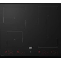


| Product type | Induction cooktop |
| Brand | Beko |
| Model | HII64822QUFT |
| Dimensions (W × D) | 600 × 520 mm |
| Height | 45 mm |
| Weight | 8 kg |
| Power supply | Electric, 220-240 V ~ 50/60 Hz |
| Total power | 7200 W |
| Number of cooking zones | 4 |
| Type of cooking zones | Induction |
| Main functions | Boost, automatic shut-off, child safety |
| Care and cleaning | Clean with a damp cloth after cooling; do not use abrasives |
| Safety | Child lock, residual heat indicator, automatic shut-off |
| Included accessories | Seal gasket, fixing springs, installation brackets |
| Repairability index | Not provided |
Frequently Asked Questions - HII64822QUFT BEKO
User questions about HII64822QUFT BEKO
0 question about this device. Answer the ones you know or ask your own.
Ask a new question about this device
Download the instructions for your Cooker in PDF format for free! Find your manual HII64822QUFT - BEKO and take your electronic device back in hand. On this page are published all the documents necessary for the use of your device. HII64822QUFT by BEKO.
USER MANUAL HII64822QUFT BEKO
EN / DE / FR / TR / BG / BS / CZ / DA / EL / ES / ET / FI / HR / HU / IT / KK / KO / LT / LV / MK / NL / NO / PL / PT / RO / RU / SK / SL / SB / SV / UK
1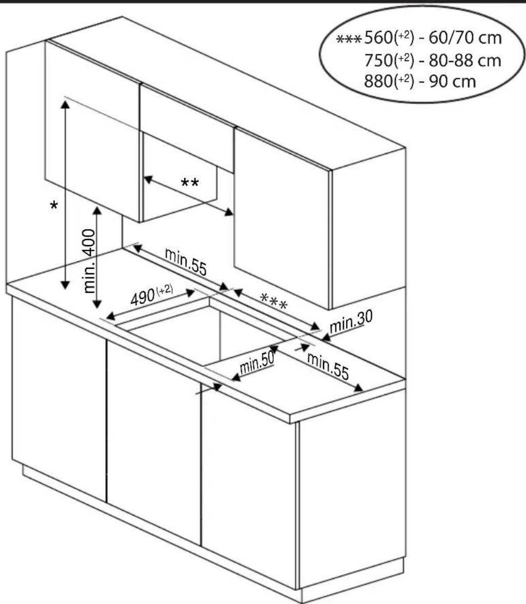
2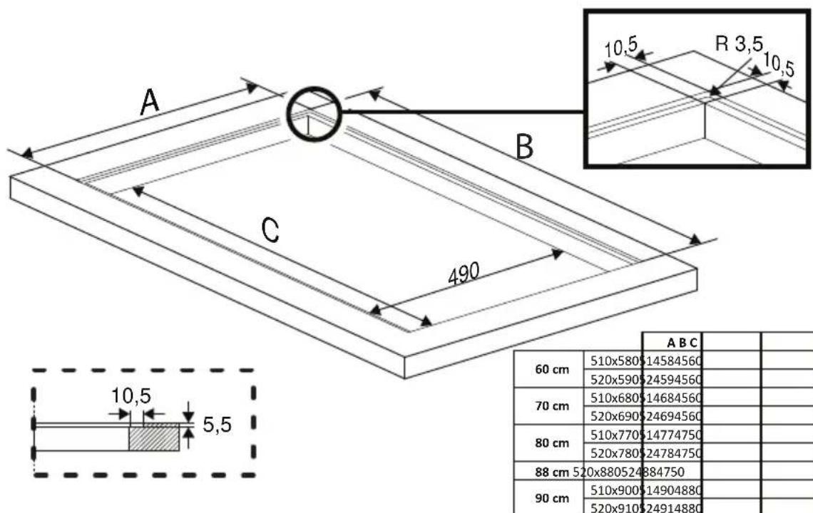
EN - Safety Instructions
- The appliance shall be installed by a qualified person in accordance with the regulations in force to keep the warranty applicable. The manufacturer shall not be held responsible for damages arising from procedures carried out by unauthorized persons which may also void the warranty.
- It is the customer's responsibility to prepare the location where the appliance shall be placed and to have the electrical installation prepared.
- The appliance shall be installed in accordance with all local gas and/or electrical regulations.
- Remove all packaging material and documents inside the appliance and check for any damage on the appliance before the installation. Do not have it installed if the appliance is damaged.
- Make sure that the user cannot reach the electrical connections after the installation.
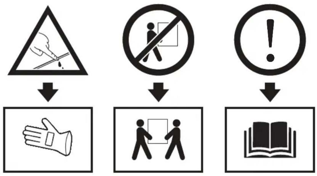
- Always wear protective gloves during transportation and installation.
- Disconnect electrical connections in the area of installation before starting the installation.
- Surfaces of the furniture that the appliance shall be installed on shall be heat resistant (100 °C minimum).
- Make sure that the furniture is in a straight, horizontal position and that it is fixed before the installation of the appliance.
- Do not install heat insulation strips to the furniture that the appliance shall be installed on.
- Dimensions given in installation diagrams are in mm.
Preparation of the furniture that the appliance shall be installed (Figures 1-2-3)
The appliance is designed for installation into commercially available worktops. A safety distance shall be left between the appliance and the kitchen walls and furniture. (Figure 1) The clearance where the appliance shall be placed on the worktop shall be cut as per the dimensions given in Figure 1.
* If there is no hood on the appliance, allow a distance of 750 mm from the hob surface to the furniture.
If a shroud/hood is installed above the appliance, allow a distance for the installation height as described in the operating manual of the shroud/hood.
** Minimum distance between the cabinets shall be equal to the width of the hob.
Flush-fit installation: (Figure 2)
- If you want to install your appliance as flush-fit with the worktop, refer to Figure 2 for the cutting dimensions of your worktop.
If the appliance shall be installed above a drawer: (Figure 3a)
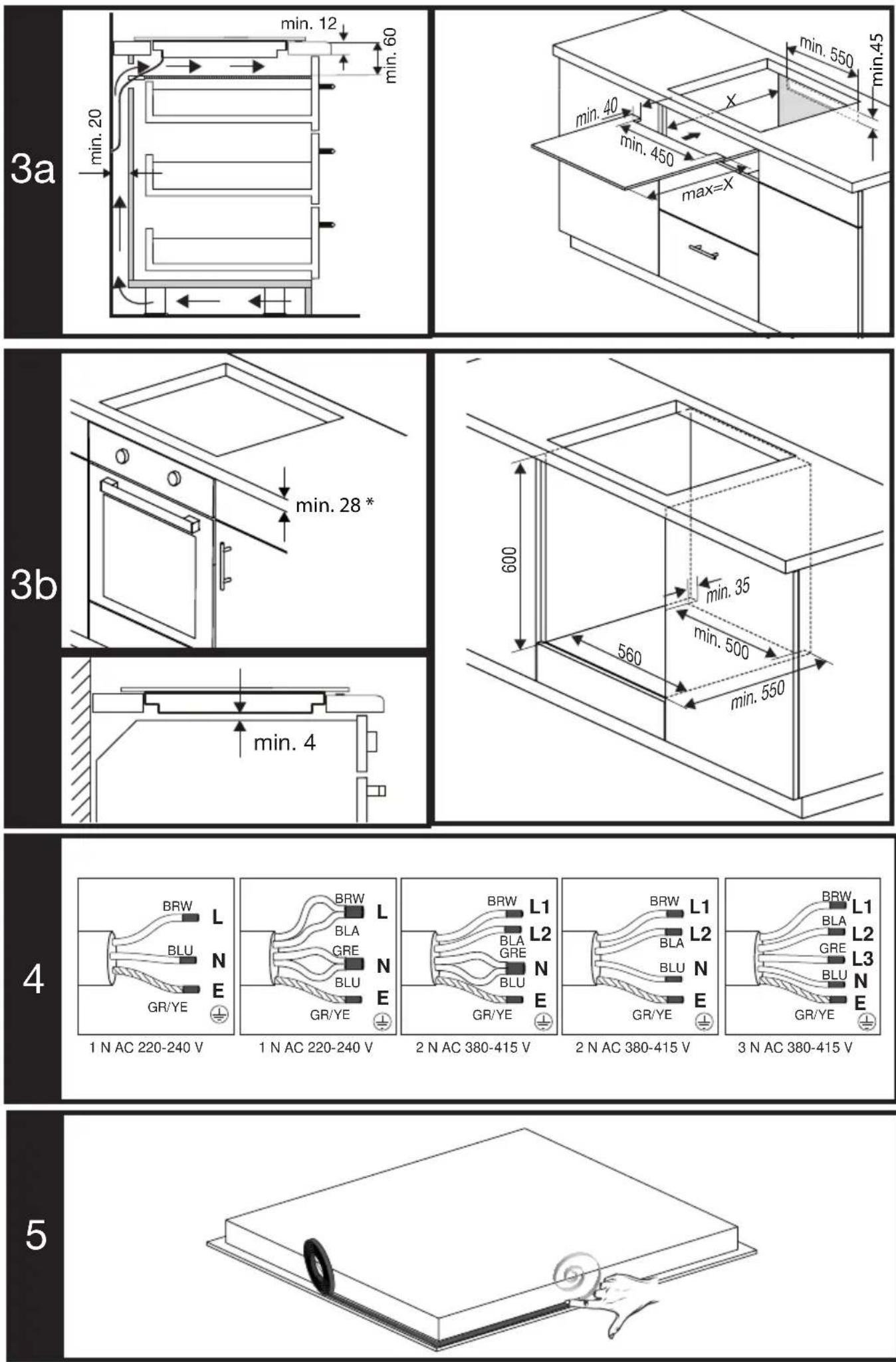
- If the appliance shall be installed on a drawer, a wooden plate/sheet shall be installed between the drawer and the cooker. A clearance with the specified dimensions shall be allowed. (Figure 3a)
- A minimum distance of 65 mm shall be allowed between the wooden plate and the worktop surface. (Figure 3a)
- Ventilation: An adequate ventilation shall be provided in the area under the appliance for the efficient operation of the appliance. For this purpose, a ventilation hole with the minimum dimensions of 550x45 mm shall be opened as shown in Figure 3a.
If the appliance shall be installed above an oven: (Figure 3b)
• Worktop thickness shall be at least 28 mm. (Figure 3b) - Ventilation: An adequate ventilation shall be provided in the area under the appliance for the efficient operation of the appliance. A minimum distance of 4 mm shall be allowed between the lower surface of the cooker and the upper wall of the oven (Figure 3b) to provide adequate ventilation. Additionally, a cross-section with the dimensions of 35x500 mm shall be left in the bottom of the furniture housing where the oven is placed. (Figure 3b)
Ventilation
- Ventilation affects the heating performance of the appliance directly. Even if no problem is detected in the first inspections, customer concerns may occur due to the performance losses while cooking for longer periods when correct ventilation clearances are not provided. Ensure that criteria 3A and 3B are met for the suitability of the furniture.
Installation of the appliance
Electrical connection of the appliance
- Connect the appliance to a grounded outlet/line with the voltage and protection as specified in the “Technical specifications” only. Have the grounding installation made by a qualified electrician while using the product with or without a transformer. Our company shall not be liable for any problems arising due to the product not being earthed in accordance with the local regulations.
- Disconnect the appliance from the electric connection before starting any work on the electrical installation. Risk of electric shock.
- The appliance may only be connected to the mains electricity connection by an authorized and qualified person. The manufacturer shall not be held responsible for any damages that may occur as a result of operations performed by unauthorized persons.
- The appliance must be installed so that it can be completely disconnected from the mains supply. The disconnection shall be provided by a switch built into the fixed electrical installation, according to the construction regulations.
- The bottom surface of the cooker gets hot, too, when it is in use. Electrical connections shall not contact the bottom surface, otherwise the connections may be damaged.
- Do not pass the connection cables over the hot surfaces. Otherwise, cable insulation may melt and cause fire as a result of short circuit of the cooker. If the electric cable is damaged, it must be replaced by a qualified electrician. Otherwise there is an electric shock,
short circuit or fire hazard!
- While performing the wiring, you shall comply with the national/local electrical regulations and shall use the appropriate socket outlet/line and plug for the cooker. In case of the product's power limits are out of current carrying capability of plug and socket outlet/ line, the product must be connected through fixed electrical installation directly without using plug and socket outlet/line.
- Make sure that fuse rating is compatible with the product.
- Connection must comply with national regulations.
- The mains supply data must correspond to the data specified on the type label of the product. You may see the type label on the bottom of the cooker.
- Power cable of your product must comply with the values in “Technical specifications” table.
- If the appliance shall be directly connected to the mains: If it is not possible to disconnect all poles in the mains supply, a disconnection unit with at least 3 mm contact clearance (fuse, line safety switch, contactor) shall be connected and all the poles of this disconnection unit shall be adjacent to (not above) the appliance in accordance with IEE directives. Failure to obey this instruction may cause operational problems and invalidate the product warranty.
• Additional protection by a residual current circuit breaker is recommended.
If your appliance has a supply cord and plug:
- Perform the electrical connection of your appliance by plugging it to a grounded socket.
If your appliance has a supply cord, but does not have a plug:
- Connect your appliance to the mains as specified below as per the supply cord type. The supply cord type of your appliance is specified in the “Specifications” section of the operation manual.
If your supply cord type is 3-conductor type, for 1-phase connection:
- (BRW) Brown = L (Phase)
- (BLU) Blue = N (Neutral)
- (GR/YE) Green/yellow wire = (E) ⏚ (Earthing)
If your supply cord type is 5-conductor type, for 1-phase connection:
For single phase connection
- (BRW/BLA) Brown/Black = L (Phase)
- (BLU/GRE) Blue/Grey = N (Neutral)
- (GR/YE) Green/yellow wire = (E) ⏚ (Earthing)
If your supply cord type is 5-conductor type, for 2-phase connection:
- (BRW) Brown = L1 (Phase)
- (BLA) Black = L2 (Phase)
- (BLU/GRE) Blue/Grey = N (Neutral)
- (GR/YE) Green/yellow wire = (E) ⏻ (Earthing)
If your supply cord type is 4-conductor type, for 1-phase connection:
- (BRW/ BLA) Brown/ Black = L (Phase)
- (BLU) Blue = N (Neutral)
- (GR/YE) Green/yellow wire = (E) ⏚ (Earthing)
If your supply cord type is 4-conductor type, for 2-phase connection:
- (BRW) Brown = L1 (Phase)
- (BLA) Black = L2 (Phase)
- (BLU) Blue = N (Neutral)
- (GR/YE) Green/yellow wire = (E) (Earthing)
If your supply cord type is 5-conductor type, for 3-phase connection:
- (BRW) Brown = L1 (Phase)
- (BLA) Black = L2 (Phase)
- (GRE) Grey = L3 (Phase)
- (BLU) Blue = N (Neutral)
- (GR/YE) Green/yellow wire = (E) ⏱ (Earthing)
For the protection of the appliance against burning:
- Make sure that the product plug is securely plugged into the outlet to avoid arcing.
- Do not use damaged cables or extension cables.
- Ensure liquid or moisture is not accessible to the electrical connection point.
Placement and securing of the appliance (Figures 5-6-7-8)
- After preparing the installation location of the appliance, turn the cooker upside down and place it on a flat surface.
- Affix the sealing gasket supplied with the appliance around the cooker so that it shall be 1-2 mm inside the outer edge of the glass as shown in Figure 5. Ensure that no clearance is left between both ends and between the glass and gasket.
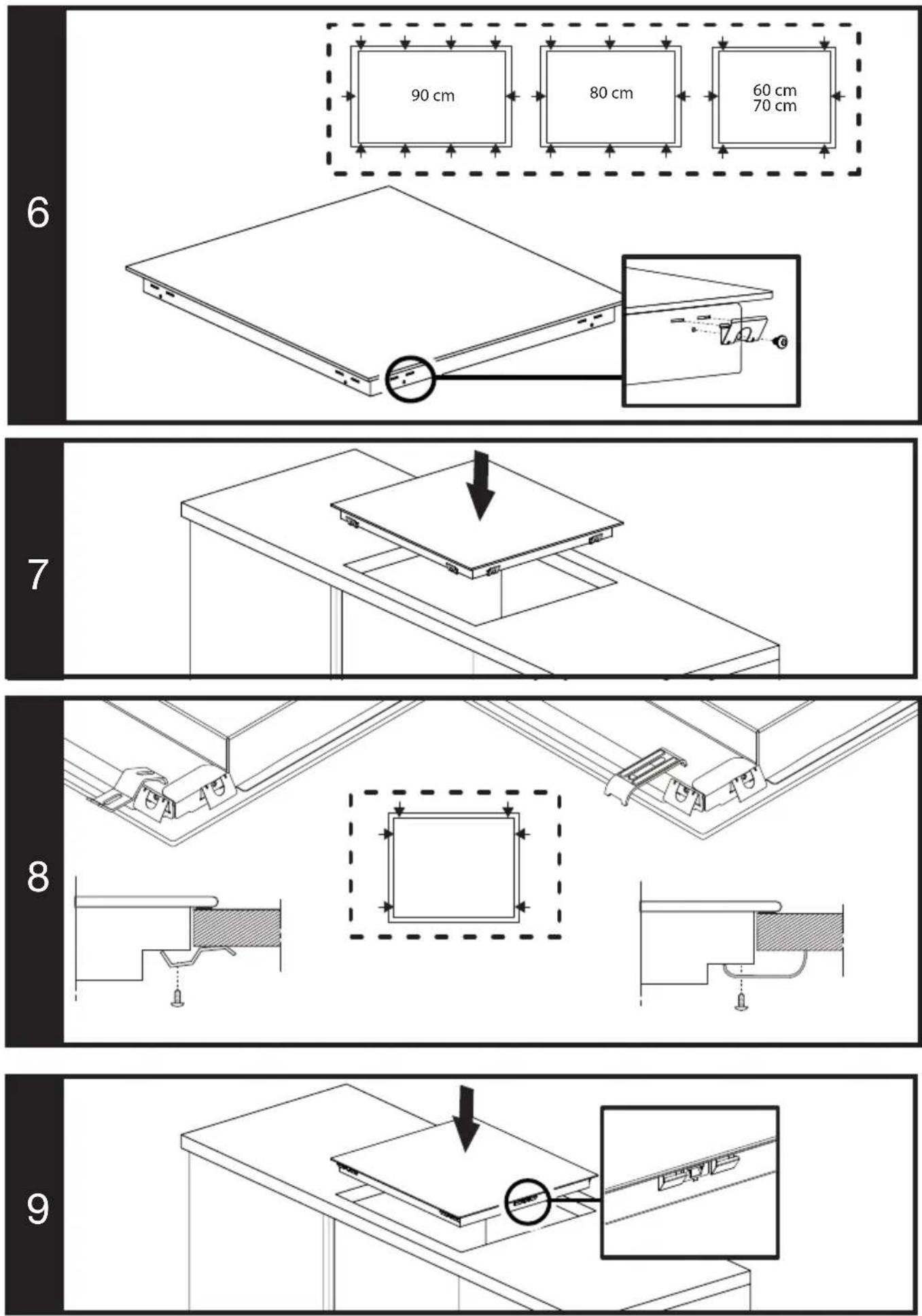
- Screw and secure the installation springs supplied with the appliance by engaging them to their seat on the lower housing of the cooker as shown in Figure 6. (In some models, these springs may be secured to the appliance ex-factory.)
- Turn the cooker again and align it with the worktop and then place it on the worktop. Cooker shall be placed on the worktop thanks to the springs, and it shall be easily secured.
- Ensure that the cooker and the worktop are parallel when you place the cooker on the worktop. When it is not in parallel, connect the additional installation clamps supplied with the appliance as shown in Figure 8. Figure 8 shows the possible installation locations of the clamps. (The locations where the clamps can be attached may vary depending on the product model. You can connect according to the mounting holes on your product.) Ensure the parallelism by attaching the clamps to the appropriate locations. The type and quantity of clamps supplied with the product may vary depending on the product model.
Placement and securing of the appliance (Figures 9)
- Figure 9 is for the models with mounting springs and sealing gasket attached to the product. For these models, ignore the pictures 5-6-7-8. For these models, consider the width and depth measurements written in the user manual as 10 mm more.
- Align the hob with the worktop and then place it on the worktop. Hob shall be placed on the worktop thanks to the springs, and it shall be easily secured.
- Ensure that the hob and the worktop are parallel when you place the hob on the worktop.
Final inspection
• After completing the installation, turn on the mains supply. - Read the operation manual for the first operation of the appliance. - Ensure that each cooking hob heats.
Removal of the appliance
- Disconnect the mains supply of the appliance.
- If your appliance is secured with additional clamps, remove the screws of the clamps first.
- Remove the cooker by pushing upward from the bottom of the cooker.
- (BRW) Braun = L (Phase)
- (BLU) Blau = N (Neutral)
- (GR/YE) Grüner/gelber Draht = (E)
(Earthing)
- (BRW/BLA) Braun/Schwarz = L (Phase)
- (BLU/GRE) Blau/Grau = N (Neutral)
- (GR/YE) Green/yellow wire = (E) ⏻ (Earthing)
- (BRW) Brown = L1 (Phase)
- (BLA) Black = L2 (Phase)
- (BLU/GRE) Blue/Grey = N (Neutral)
- (GR/YE) Green/yellow wire = (E) (Earthing)
- (BLU) Blue = N (Neutral)
- (GR/YE) Green/yellow wire = (E) ⏻ (Earthing)
- (BRW) Brown = L1 (Phase)
- (BLA) Black = L2 (Phase)
- (BLU) Blue = N (Neutral)
- (GR/YE) Green/yellow wire = (E) (Earthing)
- (BRW) Brown = L1 (Phase)
- (BLA) Black = L2 (Phase)
- (GRE) Grey = L3 (Phase)
- (BLU) Blue = N (Neutral)
- (GR/YE) Green/yellow wire = (E) ⏻ (Earthing)
- (BRW/BLA) Brown/black = L (Phase)
- (BLU) Blue = N (Neutral)
- (BRW) Brown = L1 (Phase)
- (BLA) Black = L2 (Phase)
- (BLU) Blue = N (Neutral)
- (BRW) Brown = L (Phase)
- (BLU) Blue = N (Neutral)
- (BRW/BLA) Brown/Black = L (Phase)
- (BLU/GRE) Blue/Grey = N (Neutral)
- (BRW) Brown = L1 (Phase)
- (BLA) Black = L2 (Phase)
- (BLU/GRE) Blue/Grey = N (Neutral)
- (BRW/BLA) Brown/Black = L (Phase)
- (BLU) Blue = N (Neutral)
- (BRW) Brown = L1 (Phase)
- (BLA) Black = L2 (Phase)
- (BLU) Blue = N (Neutral)
- (BRW) Brown = L1 (Phase)
- (BLA) Black = L2 (Phase)
- (GRE) Grey = L3 (Phase)
- (BLU) Blue = N (Neutral)
Flush-fit installation: (Figure 2)
- (BRW/ BLA) Brown/ Black = L (Phase)
- (BLU) Blue = N (Neutral)
- (GR/YE) Green/yellow wire = (E) ⏚ (Earth connection)
- (BRW) Brown = L1 (Phase)
- (BLA) Black = L2 (Phase)
- (BLU/GRE) Blue/Grey = N (Neutral)
- (GR/YE) Green/yellow cable = (E) ⏻ (Earth connection)
- (BRW) Brown = L1 (Phase)
- (BLA) Black = L2 (Phase)
- (BLU) Blue = N (Neutral)
- (GR/YE) Green/yellow wire = (E) ⏻ (Ground)
- (BRW) Brown = L1 (Phase)
- (BLA) Black = L2 (Phase)
- (GRE) Gray = L3 (Phase)
- (BLU) Blue = N (Neutral)
- (GR/YE) Green/yellow wire = (E) ⏻ (Ground)
- (BRW) brown = L1 (phase)
- (BLA) black = L2 (phase)
- (BLU) blue = N (neutral)
- (GR/YE) green/yellow wire = (E) ⏚ (ground)
- (BRW) Brown = L (Phase)
- (BRW) Brown = L1 (Phase)
- (BLA) Black = L2 (Phase)
- (BRW) Brown = L1 (Phase)
- (BLA) Black = L2 (Phase)
- (BRW) Brown = L (Phase)
- (BRW/BLA) Brown/Black = L (Phase)
- (BRW) Brown = L1 (Phase)
- (BLA) Black = L2 (Phase)
- (BRW) Brown = L1 (Phase)
- (BLA) Black = L2 (Phase)
- (BRW) Brown = L1 (Phase)
- (BLA) Black = L2 (Phase)
- (GRE) Gray = L3 (Phase)
- (BRW) Brown = L (Phase)
- (BLU) Blue = N (Neutral)
- (GR/YE) Green/Yellow wire = (E) ⏚ (Earth)
If your power cable is of the 5-conductor type, for single-phase connection:
- (BRW/BLA) brown/black = L (Phase)
- (BLU/GRE) blue/grey = N (Neutral)
- (GR/YE) green/yellow wire = (E) ⏚ (Earth)
If your power cable is of the 5-conductor type, for two-phase connection:
- (BRW) brown = L1 (Phase)
- (BLA) black = L2 (Phase)
- (BLU/GRE) blue/grey = N (Neutral)
- (GR/YE) green/yellow wire = (E) ⏚ (Earth)
If your power cable is of the 4-conductor type, for single-phase connection:
- (BRW/BLA) brown/black = L (Phase)
- (BLU) blue = N (Neutral)
- (GR/YE) green/yellow wire = (E) ⏚ (Earth)
If your power cable is of the 4-conductor type, for two-phase connection:
- (BRW) brown = L1 (Phase)
- (BLA) black = L2 (Phase)
- (BLU) blue = N (Neutral)
- (GR/YE) green/yellow wire = (E) ⏚ (Ground)
If your power cable is of the 5-conductor type, for three-phase connection:
- (BRW) brown = L1 (Phase)
- (BLA) black = L2 (Phase)
- (GRE) gray = L3 (Phase)
- (BLU) blue = N (Neutral)
- (GR/YE) green/yellow wire = (E) ⏚ (Ground)
To protect the device from burns:
HE
- EN - SAFETY INSTRUCTIONS
- PREPARATION OF THE FURNITURE THAT THE APPLIANCE SHALL BE INSTALLED (FIGURES 1-2-3)
- FLUSH-FIT INSTALLATION: (FIGURE 2)
- IF THE APPLIANCE SHALL BE INSTALLED ABOVE A DRAWER: (FIGURE 3A)
- IF THE APPLIANCE SHALL BE INSTALLED ABOVE AN OVEN: (FIGURE 3B)
- VENTILATION
- INSTALLATION OF THE APPLIANCE
- ELECTRICAL CONNECTION OF THE APPLIANCE
- IF YOUR APPLIANCE HAS A SUPPLY CORD AND PLUG
- IF YOUR APPLIANCE HAS A SUPPLY CORD, BUT DOES NOT HAVE A PLUG
- FOR THE PROTECTION OF THE APPLIANCE AGAINST BURNING
- PLACEMENT AND SECURING OF THE APPLIANCE (FIGURES 5-6-7-8)
- PLACEMENT AND SECURING OF THE APPLIANCE (FIGURES 9)
- FINAL INSPECTION
- REMOVAL OF THE APPLIANCE
- TO PROTECT THE DEVICE FROM BURNS
Brand : BEKO
Model : HII64822QUFT
Category : Cooker