
Alterum EN74-300 XD - Cooker Elba - Free user manual and instructions
Find the device manual for free Alterum EN74-300 XD Elba in PDF.


| Product type | Built-in gas hob |
| Brand | Elba |
| Model | Alterum EN74-300 XD |
| Width | 730 mm |
| Depth | 430 mm |
| Approximate weight | 12 kg |
| Gas supply | Natural gas G20 (20 mbar) or butane/propane G30/G31 (28-30/37 mbar) |
| Electrical supply | 220-240 V ~ 50/60 Hz |
| Available burners | 1 auxiliary (1.00 kW), 1 semi-rapid (1.75 kW), 1 triple ring (3.50 kW) |
| Electric plate | 1 rapid plate 1500 W (∅ 145 mm) |
| Ignition | Electronic integrated in thermostat knob |
| Safety | Flame safety device (thermocouple); automatic gas shut-off if flame extinguishes |
| Table material | Stainless steel and enamel |
| Glass lid | Yes (depending on model) |
| Recommended pan diameter | Auxiliary: 12-14 cm; semi-rapid: 16-24 cm; triple ring: 26-28 cm; Wok max 36 cm |
| Maintenance and cleaning | Clean with a sponge and soapy water; do not use abrasive or corrosive products |
| Spare parts | Injectors, valves, burners available from after-sales service |
| Repairability | Must be carried out by a qualified technician; use genuine parts |
| Warranty | Manufacturer's warranty (void if non-domestic use) |
Frequently Asked Questions - Alterum EN74-300 XD Elba
User questions about Alterum EN74-300 XD Elba
0 question about this device. Answer the ones you know or ask your own.
Ask a new question about this device
Download the instructions for your Cooker in PDF format for free! Find your manual Alterum EN74-300 XD - Elba and take your electronic device back in hand. On this page are published all the documents necessary for the use of your device. Alterum EN74-300 XD by Elba.
USER MANUAL Alterum EN74-300 XD Elba
BUILT-IN COOKING HOBS
TABLES ENCASTRABLES
100% ELBA QUALITY MADE IN ITALY

natural_image
Fresh spices including garlic, red chili peppers, and green peppers on a white background (no text or symbols)ELBA
TALENT FOR COOKING
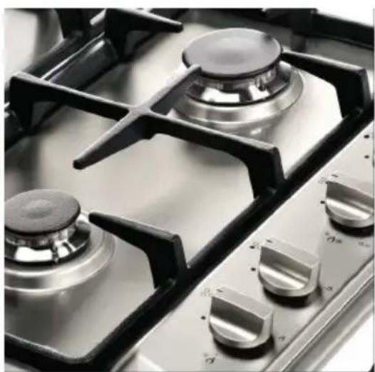
natural_image
Close-up of a stainless steel gas stove with four burners and a rotary dial (no visible text or symbols)
Made in Italy
English Instructions for the use - Installation advices
The manufacturer cannot be held responsible for possible inaccuracies due to printing or transcription errors in the present booklet.
The manufacturer reserves the right to make all modifications to its products deemed necessary for manufacturer commercial reasons at any moment and without prior notice, without jeopardising the essential functional and safety characteristics of the appliances.
Thank you for having purchased and given your preference to our product.
The safety precautions and recommendations reported below are for your own safety and that of others. They will also provide a means by which to make full use of the features offered by your appliance.
Please preserve this booklet carefully. It may be useful in future, either to yourself or to others in the event that doubts should arise relating to its operation.
This appliance must be used only for the task it has explicitly been designed for, that is for cooking foodstuffs. Any other form of usage is to be considered as inappropriate and therefore dangerous.
The manufacturer declines all responsibility in the event of damage caused by improper, incorrect or illogical use of the appliance.
IMPORTANT SAFETY PRECAUTIONS AND RECOMMENDATIONS
IMPORTANT: This appliance is designed and manufactured solely for the cooking of domestic (household) food and is not suitable for any non domestic application and therefore should not be used in a commercial environment.
The appliance guarantee will be void if the appliance is used within a non domestic environment i.e. a semi commercial, commercial or communal environment.
Read the instructions carefully before installing and using the appliance.
- This appliance has been designed and manufactured in compliance with the applicable standards for the household cooking products and it fulfills all the safety requirements shown in this manual, including those for surface temperatures.
Some people with sensitive skin may have a more pronounced temperature perception with some components although these parts are within the limits allowed by the norms.
The complete safety of the appliance also depends on the correct use, we therefore recommend to always pay a extreme attention while using the product, especially in the presence of children. - After having unpacked the appliance, check to ensure that it is not damaged.
In case of doubt, do not use it and consult your supplier or a professionally qualified technician. - Packing elements (i.e. plastic bags, polystyrene foam, nails, packing straps, etc.) should not be left around within easy reach of children, as these may cause serious injuries.
- Some appliances are supplied with a protective film on steel and aluminium parts. This film must be removed before using the appliance.
- IMPORTANT: The use of suitable protective clothing/gloves is recommended when handling or cleaning this appliance.
- Do not attempt to modify the technical characteristics of the appliance as this may become dangerous to use. The manufacturer declines all responsibility for any inconvenience resulting from the inobservance of this condition.
- CAUTION: this appliance must only be installed in a permanently ventilated room in compliance with the applicable regulations.
- Do not operate your appliance by means of an external timer or separate remote-control system.
- Do not carry out cleaning or maintenance operations on the appliance without having previously disconnected it from the electric power supply.
- Do not use a steam cleaner because the moisture can get into the appliance therefore making it unsafe.
- Do not cover the hob with aluminium foils.
- Do not touch the appliance with wet or damp hands (or feet).
- Do not use the appliance whilst in bare feet.
- If you should decide not to use this appliance any longer (or decide to substitute another model), before disposing of it, it is recommended that it be made inoperative in an appropriate manner in accordance to health and environmental protection regulations, ensuring in particular that all potentially hazardous parts be made harmless, especially in relation to children who could play with unused appliances.
- The various components of the appliance are recyclable. Dispose of them in accordance with the regulations in force in your country. If the appliance is to be scrapped, remove the power cord.
• After use, ensure that the knobs are in the off position.
- Children less than 8 years of age shall be kept away unless continuously supervised.
- This appliance can be used by children aged from 8 years and above and persons with reduced physical, sensory or mental capabilities or lack of experience and knowledge if they have been given supervision or instruction concerning use of the appliance in a safe way and understand the hazards involved. Children shall not play with the appliance. Cleaning and user maintenance shall not be made by children without supervision.
- The manufacturer declines all liability for injury to persons or damage to property caused by incorrect or improper use of the appliance.
- WARNING: During use the appliance and its accessible parts become hot; they remain hot for some time after use.
- Care should be taken to avoid touching heating elements on the hob.
- To avoid burns and scalds, young children should be kept away.
- Make sure that electrical cables connecting other appliances in the proximity of the cooktop cannot come into contact with the hob.
- WARNING: Unattended cooking on a hob with fat or oil can be dangerous and may result in fire. NEVER try to extinguish a fire with water, but switch off the appliance and then cover flame e.g. with a lid or a fire blanket.
- WARNING: Danger of fire: do not store items on the cooking surfaces.
- WARNING: If the hob is cracked or otherwise damaged by falling objects etc., disconnect the appliance from the electrical power supply to avoid the possibility of electric shock and call Customer Service.
- WARNING: When correctly installed, your product meets all safety requirements laid down for this type of product category. However special care should be taken around the underneath of the appliance as this area is not designed or intended to be touched and may contain sharp or rough edges, that may cause injury.
- CAUTION: The cooking process has to be supervised. A short term cooking process has to be supervised continuously.
- If the power supply cable is damaged, it must be replaced only by an authorized service agent in order to avoid a hazard.
Advice for the installer
• The appliance should be installed, regulated and adapted to function by a QUALIFIED INSTALLATION TECHNICIAN.
Failure to comply with this condition will render the guarantee invalid.
- The appliance must be installed in compliance with regulations in force and following the manufacturer's instructions.
• Installation technicians must comply to current laws in force concerning ventilation and the evacuation of exhaust gases.
• Always unplug the appliance before carrying out any maintenance operations or repairs.
• The appliance must be housed in heat-resistant units.
• These tops are designed to be embedded into kitchen fixtures measuring 600 mm in depth. - The walls of the units must not be higher than work top and must be capable of resisting temperatures of 75^ above room temperature.
- Do not install the appliance near inflammable materials (eg. curtains).
WARNING
When correctly installed, your product meets all safety requirements laid down for this type of product category.
However special care should be taken around the underneath of the appliance as this area is not designed or intended to be touched and may contain sharp or rough edges, that may cause injury.
TECHNICAL INFORMATION FOR THE INSTALLER
Before installing the hob, remove the protective film.
This hob may be built into a worktop of 30 to 40 mm thick and 600 mm deep.
In order to install the hob into the kitchen cabinet, an aperture with the dimensions shown in fig. 1.2 has to be made, keeping in consideration the following:
- inside the cabinet, between the bottom side of the hob and the upper surface of any other appliance or internal shelf there must be a clearance of at least 30 mm;
- the hob must be installed no less than 200 mm away from any side wall;
- the hob must be installed at a distance of no less than 50 mm from the rear wall.
- there must be a distance of at least 650 mm between the hob and any wall cabinet or extractor hood positioned immediately above (see fig. 1.1).
• the coatings of the walls of the unit or appliances near the hob must be heat resistant.
Do not install the appliance near inflammable materials (eg. curtains).
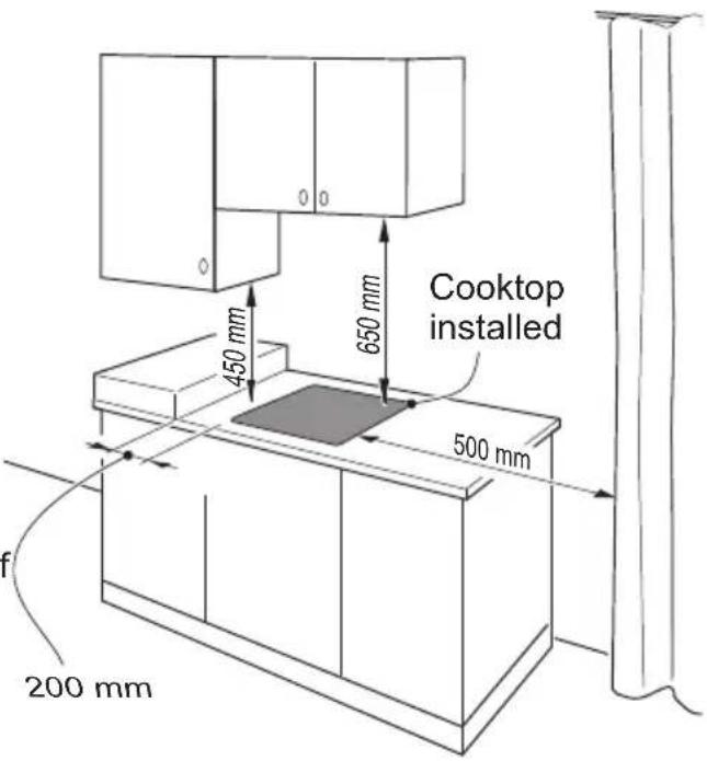
Fig. 1.1
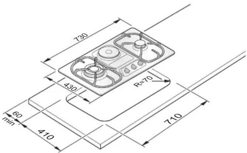
Fig. 1.2
CUPBOARD DOORS (fig. 1.3)
The installation has to be made according to specific requirements in order to prevent the gas burners from going out, even when the flame is turned down to minimum, due to pressure changes while opening or closing the cupboard doors.
It is recommended that a 30 mm clearance be left between the hob and the partition surface underneath.
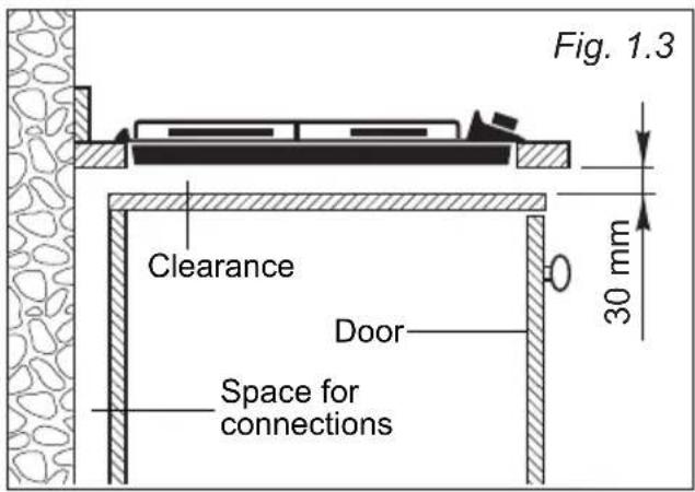
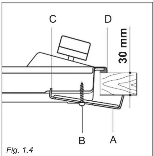
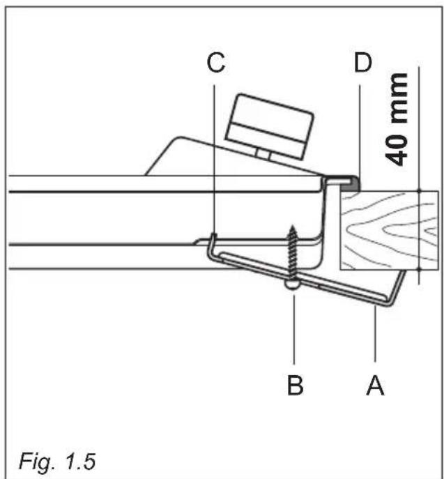
FASTENING THE INSTALLATION BRACKETS (figs. 1.4, 1.5)
Each hob is supplied with a set of tabs and screws to fasten it on units with a worktop 3 to 4 cm deep.
The kit includes 4 tabs "A" and 4 selftapping screws "B".
- Cut the unit.
- Stretch gasket "D" over the edge of the hole made, being careful to overlay the junction edges.
- Turn the hob over and put tabs "A" (fig. 1.4 - 1.5) into the housings, only tighten screws "B" a few turns.
Make sure that the tabs are mounted correctly as shown in the figure 1.4 - 1.5. Turn the tabs so that the cooktop can be dropped into the aperture.
- Lay the hob into the aperture of the unit and position it correctly.
- Put tabs "A"; into place, tooth "C" of the tabs should go into the hole.
- Tighten screws "B" until the hob is completely secured.
- Using a sharp tool cut off the part of gasket "D" which protrudes from the cooktop. Take care not to damage the benchtop.
VENTILATION REQUIREMENTS
The appliance must be installed in compliance with applicable local regulations concerning ventilation and the evacuation of exhaust gases.
Intensive and prolonged use may require extra ventilation, e.g. opening a window, or more efficient ventilation increasing the mechanical suction power if this is fitted.
The room where the gas appliance is to be installed must have a natural flow of air so that the gas can burn (in compliance with applicable local regulations).
The flow of air must come directly from one or more openings made in the outside walls with a free area of at least 100 cm^2 (or refer to applicable local regulations).
The openings should be near the floor and preferably on the side opposite the exhaust for combustion products and must be made so that they cannot be blocked from either the inside or the outside.
When these openings cannot be made, the necessary air can come from an adjacent room which is ventilated as required, as long as it is not a bed room or a danger area (in compliance with applicable local regulations).
In this case, the kitchen door must allow the passage of the air.
DISCHARGING PRODUCTS OF COMBUSTION
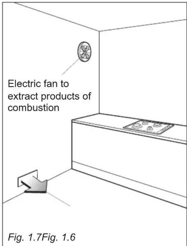
Extractor hoods connected directly to the outside must be provided, to allow the products of combustion of the gas appliance to be discharged (fig. 1.6).
If this is not possible, an electric fan may be used, attached to the external wall or the window; the fan should have a capacity to circulate air at an hourly rate of 3-5 times the total volume of the kitchen (fig. 1.7).
The fan can only be installed if the room has suitable vents to allow air to enter, as described under the heading “Choosing suitable surroundings”.
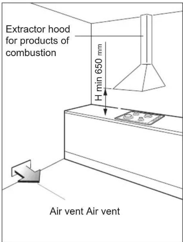
GAS INSTALLATION REQUIREMENTS
Important!
- The walls adjacent to the cooker must be of heat-resistant material.
- Before installation, make sure that the local distribution conditions (gas type and pressure) and the adjustment of this appliance are compatible. The appliance adjustment conditions are given on the plate or the label.
- This appliance must be installed and serviced only by a suitably qualified, registered installer. The installer shall refer to the local standards in force.
- Failure to install the appliance correctly could invalidate any manufacturer's warranty.
This appliance is supplied for use on LPG (Cat. I 3+, G30/G31 28-30/37 mbar; check the gas regulation label attached on the appliance).
OR
This appliance is supplied for use on NATURAL GAS or LPG (Cat. II 2H 3+, G20 20 mbar, G30/G31 28-30/37 mbar; check the gas regulation label attached on the appliance).
- Appliances supplied for use on NATURAL GAS: they are adjusted for this gas only and cannot be used on any other gas (LPG) without modification. The appliances are manufactured for conversion to LPG.
- Appliances supplied for use on LPG: they are adjusted for this gas only and cannot be used on any other gas (NATURAL GAS) without modification. The appliances are manufactured for conversion to NATURAL GAS.
If the NATURAL GAS/LPG conversion kit is not supplied with the appliance this kit can be purchased by contacting the After-Sales Service.
CONNECTING THE COOKTOP TO THE GAS SUPPLY
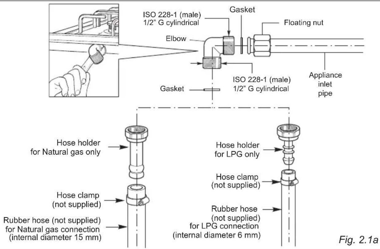
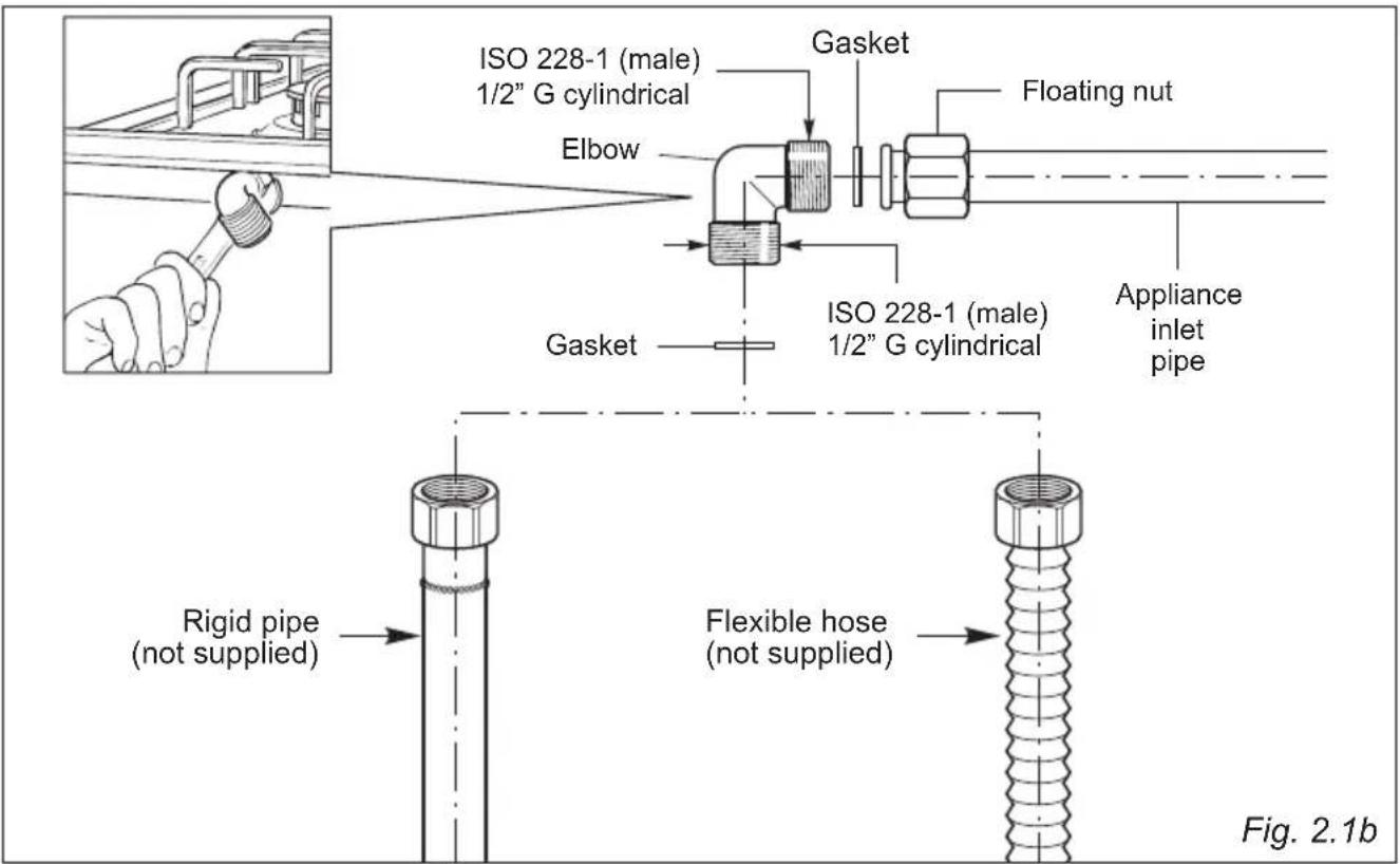
The gas connection fitting (figs. 2.1a - 2.1b) is made up of:
- the floating nut;
- the elbow;
- the gaskets;
the hose holder for Natural gas or LPG - to be used for gas connection with a rubber hose.
Important! A rubber hose connection shall only be made if permitted by the applicable local regulations.
If the hose holder is not supplied with the appliance it can be purchased by contacting the After-Sales Service.
The gas connection must be carried out by an authorised person according to the relevant local standards.
- If using a flexible hose, make sure it does not come into contact with moving parts.
- The rear of the chassis is recessed to provide a channel for the appliance inlet pipe.
- The gas connection fitting can be turned in the direction required (but never in a vertical or horizontal position) after loosening the elbow and floating nut connection.
- Never attempt to turn the elbow without having first loosened the floating nut.
- The supplied gaskets guarantee a good seal for the gas connection. We recommend that you replace the gaskets on the slightest sign of wear, deformation or imperfection.
After connecting to the gas mains, check that the couplings are correctly sealed, using soapy solution, but never a naked flame.
Gas connection with rigid pipes or a flexible pipe
ADDITIONAL GAS CONNECTION REQUIREMENTS
When connecting the cooktop to the gas supply with a rubber hose, make sure that:
- If not already fitted, you fit the Natural gas or LPG hose holder on the inlet pipe, making sure that you place the sealing washer between them (as shown in Fig. 6.1). If the hose holder is not supplied with the appliance it can be purchased by contacting the After-Sales Service.
- You connect the cooktop to the gas supply using a suitable rubber hose (internal diameter 15 mm for Natural gas or internal diameter 6 mm for LPG). The hose must comply with the applicable local regulations and be of the correct construction for the type of gas being used.
- You make sure that the hose is tightly and securely fitted at both ends.
- You use a standard hose clamp (not supplied) to fasten the hose.
- The hose is as short as possible, without twists or kinks.
- The hose is not longer than 750 mm (or refer to applicable local regulations) and does not come into contact with sharp edges, corners or moving parts.
- The hose does not come into contact with any part of the cooktop with a surface temperature of 70^ or above (or refer to applicable local regulations).
- The hose can easily be inspected along its entire length to check its condition.
- The hose is replaced at the printed due date or if it shows signs of wear or damage, and replaced regardless of its condition after a maximum of three years.
- You inform the customer that the hose should not be subjected to corrosion by acidic cleaning agents.
When connecting the cooktop to the gas supply with rigid pipes or a flexible hose, make sure that:
- You use rigid pipes or a flexible hose compliant with applicable local regulations. The flexible hose shall be of the correct construction for the type of gas being used and of the correct size to maintain the heat output of the appliance.
- The connection with rigid metal pipes does not cause stress or pressure to the gas piping.
- The flexible hose is not under tension, twisted, kinked, or too tightly bent, neither while the cooktop is in use nor while it is being connected or disconnected.
- The flexible hose is not longer than 2000 mm (or refer to applicable local regulations) and does not come into contact with sharp edges, corners, or moving parts, as these may cause abrasion. Use a single flexible hose only; never connect the cooktop with more than one flexible hose.
- The flexible hose can easily be inspected along its entire length to check its condition; if it has an expiry date, it should be replaced before that date.
- If using a flexible hose which is not entirely made of metal, make sure that it does not come into contact with any part of the cooktop with a surface temperature of 70^ or above (or refer to applicable local regulations).
- The rigid pipe or flexible hose is replaced if it shows signs of damage.
- The flexible hose is not subject to excessive heat by direct exposure to flue products or by contact with hot surfaces.
- The socket into which the plug of the flexible hose fit is permanently attached to a firmly fixed gas installation pipe and is positioned so that the hose hangs freely downwards.
- The plug of the flexible hose is accessible after installation, so that it can be disconnected for service or removal.
- You inform the customer that the rigid pipe or flexible hose should not be subjected to corrosion by cleaning agents.
Some models - for the gas category check the data label attached on the appliance
| TABLE FOR THE CHOICE OF THE INJECTORS | |||
| Cat: I 3+ | G30/G3128-30/37 mbar | ||
| BURNERS | Nominal Power [kW] | Reduced Power [kW] | ∅ injector[1/100 mm] |
| Auxiliary (A) 1,00 0,30 50 | |||
| Semi-rapid (SR) 1,75 0,45 66 | |||
| Triple-ring (TR) 3,50 1,50 93 | |||
Some models - for the gas category check the data label attached on the appliance
| TABLE FOR THE CHOICE OF THE INJECTORS II 2H 3+ | ||||
| BURNERS | Nominal power [kW] | Reduced power [kW] | LPG G30/G31 28-30/37 mbar | Natural Gas G20 20 mbar |
| ∅ injector [1/100 mm] | ∅ injector [1/100 mm] | |||
| Auxiliary (A) 1,00 0,30 50 77 | ||||
| Semi-rapid (SR) 1,75 0,45 66 101 | ||||
| Triple-ring (TR) 3,50 1,50 93 135 | ||||
| AIR VENT NECESSARY FOR GAS COMBUSTION = (2 m3/h x kW) | |
| BURNERS Air necessary for combustion [m 3/h] | |
| Auxiliary (A) 2,00 | |
| Semi-rapid (SR) 3,50 | |
| Triple-ring (TR) 7,00 | |
LUBRICATION OF THE GAS TAPS
The operations must be executed by a qualified technician.
IMPORTANT: All intervention regarding installation maintenance and conversion of the appliance must be fulfilled with original factory parts.
The manufacturer declines any liability resulting from the non-compliance of this obligation.
REPLACEMENT OF THE INJECTORS
Select the injectors to be replaced according to the "TABLE FOR THE CHOICE OF THE INJECTORS".
The nozzle diameters, expressed in hundredths of a millimetre, are marked on the body of each injector.
If the injectors are not supplied they can be obtained from the "Service Centre".
REPLACEMENT OF THE INJECTORS OF THE COOKTOP BURNERS
To replace the injectors proceed as follows:
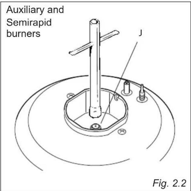
- Remove pan supports and burners from the cooktop.
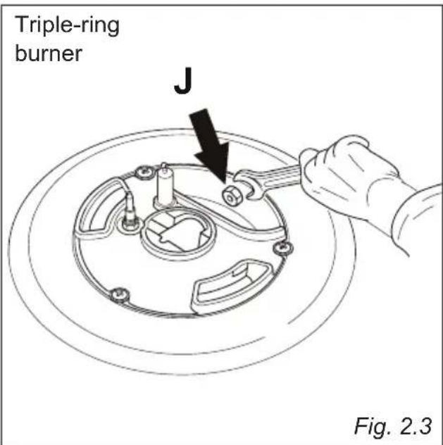
- Using a wrench, substitute the injectors "J" (figs. 2.2, 2.3) with those most suitable for the kind of gas for which it is to be used.
The burners are conceived in such a way so as not to require the regulation of the primary air.
SETTING THE MINIMUM OF THE COOKTOP BURNERS
In the minimum position the flame must have a length of about 4 mm and must remain lit even with a quick turn from the maximum position to that of minimum.
The flame adjustment is done in the following way:
- Turn on the burner.
- Turn the tap to the 'MINIMUM' position.
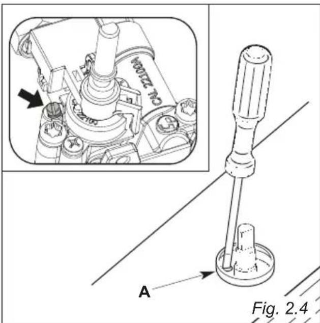
• Take off the knob. - With a small flat screwdriver turn the screw "A" to the correct regulation (fig. 2.4).
Normally for LPG tighten up the regulation screw.
IMPORTANT: The appliance must be installed by a qualified technician according with the current local regulations and in compliance with the manufacturer instructions. Incorrect installation might cause harm and damage to people, animals or objects, for which the manufacturer accepts no responsibility.
Connection to a good earth wiring system is absolutely essential.
The manufacturer accepts no responsibility for any inconvenience caused by failure to comply with this rule.
Before carrying out any work on the electrical section of the appliance, it must be disconnected from the mains.
DETAILS
- Connection to the electric power supply must be carried out by a qualified technician and following the appropriate safety regulations;
- Before carrying out the connection to the power supply, the voltage rating of the appliance (stamped on the appliance identification plate) must be checked for correspondence to the available mains supply voltage, and the mains electric wiring should be capable of handling the hob's power rating (also indicated on the identification plate);
- If the hob is supplied without a power supply plug and therefore if you are not connecting directly to the mains, a standardized plug suitable for the load must be fitted.
- The power point must be connected to a suitable earth wiring, in conformity to current safety regulations.
- It is possible to connect the appliance directly to the mains supply by means of a heavy duty switch with 3 mm minimum distance between the contacts.
- The power supply cord must not touch against any hot surfaces and must be placed so that its temperature does not exceed 75^ at any point along its length.
- Once the appliance has been installed, the switch or socket must always be accessible.
- The appliance must have its own supply; any other appliances installed near it must be supplied separately.
- N.B. For connections to the mains power supply, never use adapters, reductions or multiple power points as these may overheat and catch fire.
- If the hob surface is cracked disconnect the appliance from the mains and contact the After-Sales Service.
In the event that installation should require modifications to the mains supply wiring system or if the power plug is not suitable for the type of power point available, it is recommended that a qualified technician be called to carry out substitution.
The technician will also have to verify that the cross-section of the electric cables on the power point match the appliance's power rating.
POWER SUPPLY CABLE
- The supply cable must be replaced with a cable of the same type.
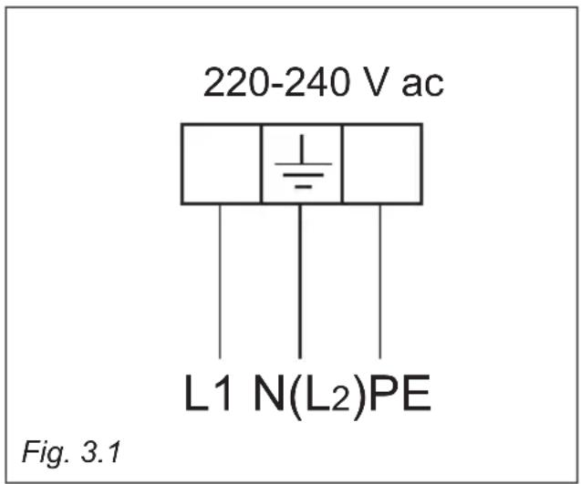
- The electrical cable must be connected to the terminal board following the diagram of fig. 3.1.
The operations must be executed by a qualified technician.
FEEDER SPECIAL CABLE SECTION TYPE "H05RR-F"
(*) Connection possible with plug and outlet
(**) Connection with wall box connection.
WARNING: If the power supply cable is damaged, it must be replaced only by an authorised service agent in order to avoid a hazard.
Advice for the users
"2 GAS " COOKING HOB
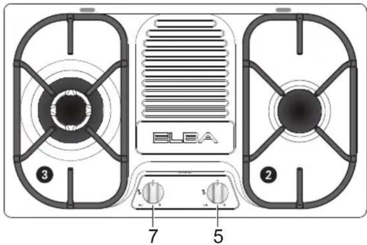
Fig. 1.2a
"3 GAS" COOKING HOB
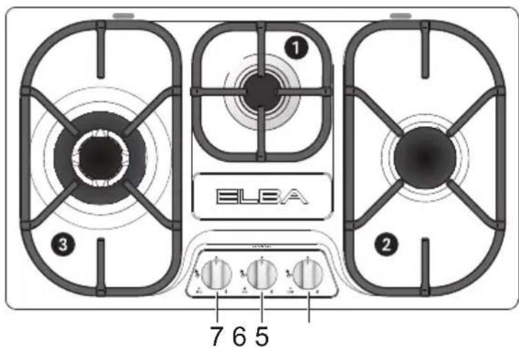
Fig. 1.1b
"2 GAS + 1 ELECTRIC PLATE" COOKING HOB
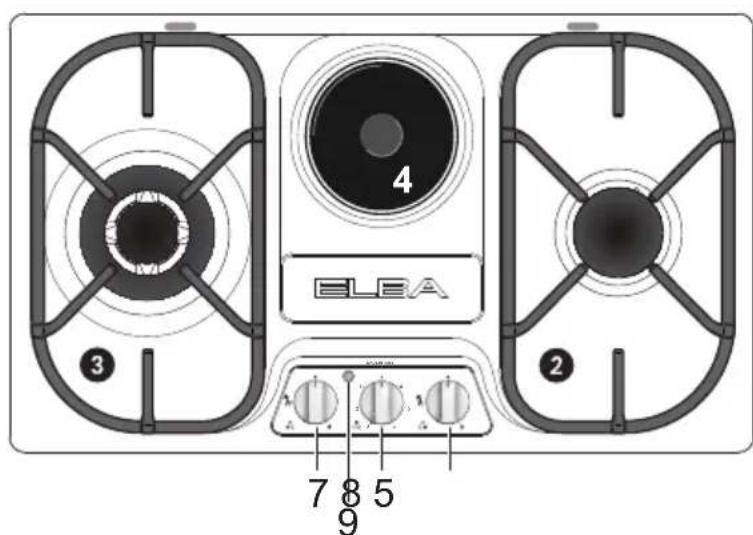
Fig. 1.1c
GAS BURNERS
- Auxiliary burner (A) 1,00 kW
- Semirapid burner (SR) 1,75 kW
- Triple ring burner (TR) 3,50 kW
- Electrical plate (rapid ∅ 145 mm) 1500 W
CONTROL PANEL DESCRIPTION
- Burner 2 (SR) control knob
- Burner 1 (A) control knob
- Burner 3 (TR) control knob
- Electric plate 4 control knob
- Electric hotplate indicator light
NOTE:
- The electric ignition is incorporated in the knobs.
- The models has a safety valve system fitted, the flow of gas will be stopped if and when the flame should accidentally go out.
CAUTION:
If the burner is accidentally extinguished, turn the gas off at the control knob and wait at least 1 minute before attempting to relight.
CAUTION:
Gas hobs produce heat and humidity in the environment in which they are installed. Ensure that the cooking area is well ventilated by opening the natural ventilation grilles or by installing an extractor hood connected to an outlet duct.
CAUTION:
If the hob is used for a prolonged time it may be necessary to provide further ventilation by opening a window or by increasing the suction power of the extractor hood (if fitted).
GAS BURNERS
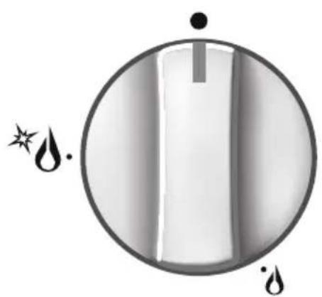
Gas flow to the burners is adjusted by turning the knobs (illustrated in fig. 2.1) which control the safety valves.
Turning the knob, so that the indicator line points to the symbols printed on the panel, achieves the following functions:
- symbol

closed valve
- symbol

maximum aperture or flow
- symbol

minimum aperture or flow
√ The maximum aperture position permits rapid boiling of liquids, whereas the minimum aperture position allows slower warming of food or maintaining boiling conditions of liquids.
√ To reduce the gas flow to minimum rotate the knob further anti-clockwise to point the indicator towards the small flame symbol.
√ Other intermediate operating adjustments can be achieved by positioning the indicator between the maximum and minimum aperture positions, and never between the maximum aperture and closed positions.
N.B. When the cooktop is not being used, set the gas knobs to their closed positions and also close the cock valve on the gas bottle or the main gas supply line.
natural_image
Simple diagram of a droplet inside a circle with stars and droplets, no text or symbols present.Fig. 2.1
NOTE: The knob and symbols may vary.

natural_image
Simple line drawing of a bag with arrows indicating motion or flow, no text or symbols presentFig. 2.2
Caution! Do not cover the hob with aluminium foils.
Caution! The cooking hob becomes very hot during operation. Keep children well out of reach.
To ignite the burner, the following instructions are to be followed:
- Press in the corresponding knob and turn counter-clockwise (fig. 2.2) to the full flame position marked by the symbol (fig. 2.1); hold the knob in until the flame has been lit.
In the case of a mains failure light the burner with a match or lighted taper. - Wait for a few seconds after the gas burner has been lit before letting go of the knob (valve activation delay).
- Adjust the gas valve to the desired position.
If the burner flame should go out for some reason, the safety valve will automatically stop the gas flow.
To re-light the burner, return the knob to the closed “●” position, wait for at least 1 minute and then repeat the lighting procedure.
Note: If your local gas supply makes it difficult to light the burner with the knob set to maximum, set the knob to minimum and repeat the operation.
natural_image
Line drawing of a cooking pot on a gas stove (no text or symbols)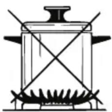
natural_image
Simple line drawing of a cooking pot with two crossed panes (no text or symbols)Fig. 2.3
CHOICE OF THE BURNER
On the control panel, near every knob there is a diagram that indicates which burner is controlled by that knob.
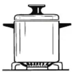
The suitable burner must be chosen according to the diameter and the capacity used.
The burners and pans must be used in accordance with the following instructions:
DIAMETERS OF PANS WHICH MAY BE USED ON THE BURNERS
NOTE: Depending on the model, the cooktop may only have some of the following burners
| BURNERS | MINIMUM | MAXIMUM |
| Auxiliary | 12 cm | 14 cm |
| Semirapid | 16 cm | 24 cm |
| Triple-ring | 26 cm | 28 cm |
| Wok Max 36 cm | ||
do not use pans with concave or convex bases
It is important that the diameter of the pot be suitable to the potentiality of the burner so as not to compromise the high output of the burners and therefore energy waste. A small pot on a large burner does not give you a boiling point in a shorter amount of time since the capacity of heat absorption of a liquid mass depends on the volume and the surface of the pot. Too large a pot can cause damage to the burner and surrounding hob area.
CAUTION: Make sure the pans are central to the burner for maximum stability and greater efficiency.
Make sure the pans are not in contact with the control knobs, otherwise the flame could overheat the knobs and permanently damage them.
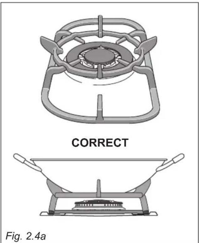
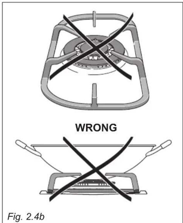
SPECIAL WOK GRILLE
(figs. 2.4a - 2.4b)
This special grille for woks should be placed over the pan-rest for the triple ring burner.
Warning:
• Using woks without this special grille may cause the burner to malfunction.
- Do not use the grille for ordinary, flat-bottomed saucepans.
IMPORTANT:
The special grille for wok pans MUST BE PLACED ONLY over the pan-rest for the triple-ring burner.
ELECTRIC HOTPLATE (Models with electric hotplate only)
RAPID HOTPLATE (red dot)
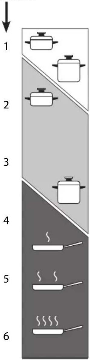
To switch on the rapid hotplate, turn the knob (fig. 2.5) onto the desired position; the numbers "1" to "6" indicate the working positions with the increase of temperature according to the number.
Once boiling point has been reached, reduce the input according to the heating intensity desired, keeping in mind that the plate will continue to heat for 5 minutes after having been turned off.
The features of this plate, which is equipped with a heat limiter, allow:
- reaching the temperature rapidly;
- maximum exploitation of the input with flat bottom pots;
- the limitation of input in the case of unsuitable pots.
WARNING:
If the surface is cracked, switch off the appliance to avoid the possibility of electric shock.
Caution! The cooking hob becomes very hot during operation.
Keep children well out of reach.
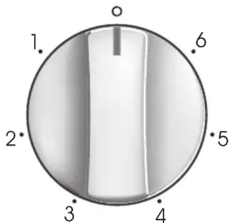
Fig. 2.5
PROPER USE OF THE ELECTRIC HOTPLATE (fig. 2.6)
When the pan comes to the boil, turn the heat down to the level desired.
Remember that the hotplate will continue to produce heat for about five minutes after it has been turned off.
While using the electric hotplate, you must:
- avoid keeping it on without something on it;
- avoid pouring liquids on it while it is hot;
- use flat-bottomed (electric hotplate type) pots and pans only;
- use cooking receptacles which cover as much of the surface of the hotplate as possible;
• to save electricity, use lids whenever possible; - never cook food directly on the hotplate: always use a pan or suitable container.
An indicator light located on the control panel signals that the hotplate is operating.
Never cook food directly on the electric hotplates! Always use a saucepan or special container.
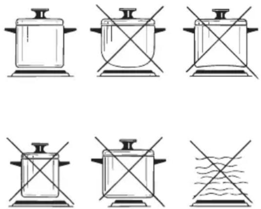
Fig. 2.6
Cooking zone controlled by a 7 position switch

Heating

Cooking

Roasting-frying
Fig. 2.7
COOKING HINTS
| Knob setting | TYPE OF COOKING |
| O Switched OFF | |
| 12 | For melting operations (butter, chocolate). |
| 2 | To maintain food hot and to heat small quantities of liquid (sauces, eggs). |
| 3 | To heat bigger quantities; to whip creams and sauces (vegetables, fruits, soups). |
| 34 | Slow boiling, i.e.: boiled meats, spaghetti, soups, continuations of steam cooking of roasts, stews, potatoes. |
| 4 | For every kind of frying, cutlets, uncovered cooking, i.e.: risotto. |
| 45 | Browning of meats, roasted potatoes, fried fish, omelettes, and for boiling large quantities of water. |
| 6 | Fast frying, grilled steaks, etc. |
Caution! Do not cover the hob with aluminium foils.
After a short period of use, experience will teach you which setting is the right one for your needs.
GENERAL ADVICE
- Before you begin cleaning, you must ensure that the appliance is switched off and disconnected from the electrical power supply.
- Important: The use of suitable protective clothing/gloves is recommended when handling or cleaning of this appliance.
• Under no circumstances should any external covers be removed for servicing or maintenance except by suitable qualified personnel. - It is advisable to clean when the appliance is cold and especially when cleaning the enamelled parts.
- Be very careful that no water penetrates inside the appliance.
- Avoid leaving alkaline or acidic substances (lemon juice, vinegar, etc.) on the surfaces.
- Avoid using cleaning products with a chlorine or acidic base.
- Do not use a steam cleaner because the moisture can get into the appliance thus make it unsafe.
- Clean surfaces with a damp cloth and use gentle, neutral cleaning products. Dry with a clean, dry cloth.
- IMPORTANT: Do not use any abrasive products (e.g. certain types of sponge) and/or aggressive products (e.g. caustic soda, products containing corrosive substances), which could cause irreparable surface damage.
COOKING HOBS WITH
GLASS LID (optional)
natural_image
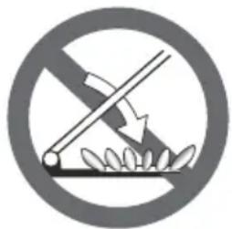
Prohibition sign showing a crossed-out fence with leaves, enclosed in a circle (no text)Do not shut lid when burner alight.
ATTENTION
√ Do not lower the glass lid when the gas burner or electrical plates are still hot and when the oven, installed below the cooking hob, is on or still hot.
√ Do not lay on the glass lid hot pans and heavy kitchen utensils.
√ Dry off any liquid which may have spilt on the cover before opening it.
WARNING! When correctly installed, your product meets all safety requirements laid down for this type of product category. However special care should be taken around the underneath of the appliance as this area is not designed or intended to be touched and may contain sharp or rough edges, that may cause injury.
ENAMELLED SURFACES
All the enamelled parts must be cleaned with a sponge and soapy water only or other non-abrasive products. Dry preferably with a microfibre or soft cloth. If acid substances such as lemon juice, tomato conserve, vinegar etc. are left on the enamel for a long time they will etch it, making it opaque.
STAINLESS STEEL SURFACES
Stainless steel parts must be rinsed with water and dried with a soft and clean cloth. For persistent dirt, use specific non-abrasive products available commercially or a little hot vinegar.
Important: The manufacturer declines all liability for possible damage caused by the use of unsuitable products to clean the appliance.
Attention! The appliance gets very hot, mainly around the cooking areas. It is very important that children are not left alone in the kitchen when you are cooking.
Do not use a steam cleaner because the moisture can get into the appliance thus make it unsafe.
PAINTED PARTS AND SILKSCREEN PRINTED SURFACES
Clean using an appropriate product. Always dry thoroughly.
IMPORTANT: these parts must be cleaned very carefully to avoid scratching and abrasion. You are advised to use a soft cloth and neutral soap.
CAUTION: Do not use abrasive substances or non-neutral detergents as these will irreparably damage the surface.
GAS TAPS
Do not let cleaning products come into contact with the valves.
Periodic lubrication of the gas taps must be carried out by specialist personnel only. In the event of operating faults in the gas taps, call the Service Department.
HOT PLATE (MODELS WITH CAST IRON ELECTRICAL HOTPLATE ONLY)
Clean the electric plates regularly with a damp cloth.
Switch them on for a couple minutes to dry them so as to avoid rust formation on the surface.
To maintain the plates in good aspect use suitable products or spread a veil of oil at times.
Do not use lubrificant or salt.
Dirty plates can be cleaned with detergents normally used for washing-up, except for abrasive products. Carefully rinse the plates then let them dry.
BURNERS AND PAN SUPPORTS
These parts must be cleaned using a sponge and soapy water or other suitable non-abrasive products. Dry with a soft cloth.
Warning! Not dishwasher safe.
If left on the surface for a length of time, acidic substances such as lemon juice, tomato sauces and passata, vinegar and other similar products will damage the surface and dull its shine.
After cleaning, the burners and their flame spreaders must be well dried and correctly replaced.
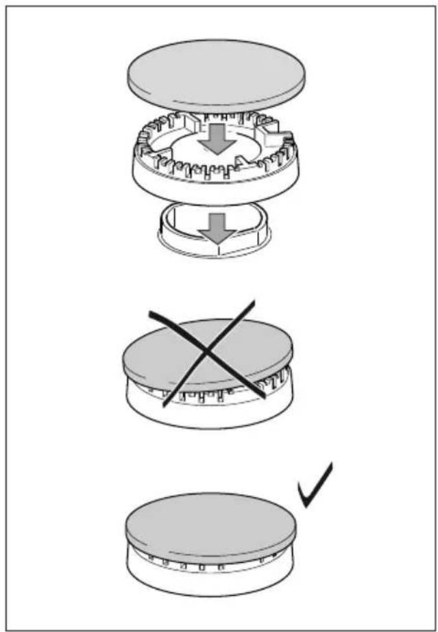
It is very important to check that the burner flame spreader and the cap have been correctly positioned. Failure to do so can cause serious problems.
Check that the electrode "S" (figs. 3.1, 3.3) next to each burner is always clean to ensure trouble-free sparking.
Check that the probe "T" (figs. 3.1, 3.3) next to each burner is always clean to ensure correct operation of the safety valves.
Both the probe and ignition plug must be very carefully cleaned.
Note: To avoid damage to the electric ignition do not use it when the burners are not in place.
Note: Continuous use may cause a change in the glaze around the burners and grids, corresponding to the areas exposed to the heat. This is a natural phenomenon and does not prevent the parts from working properly.
CORRECT REPLACEMENT OF THE AUXILIARY AND SEMI-RAPID BURNERS
It is very important to check that the burner flame distributor “F” and the cap “C” have been correctly positioned (see figs. 3.1, 3.2) - failure to do so can cause serious problems.
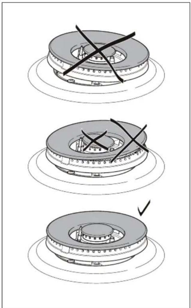
CORRECT REPLACEMENT OF THE TRIPLE RING BURNER
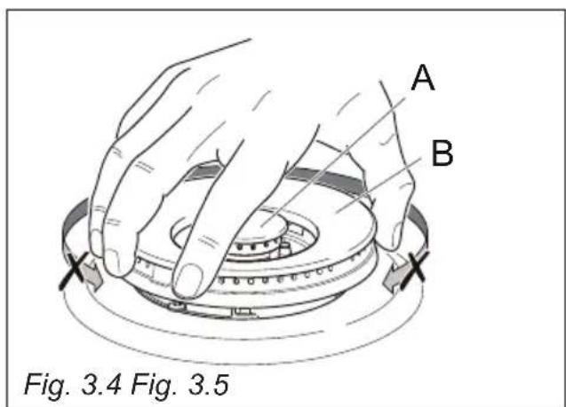
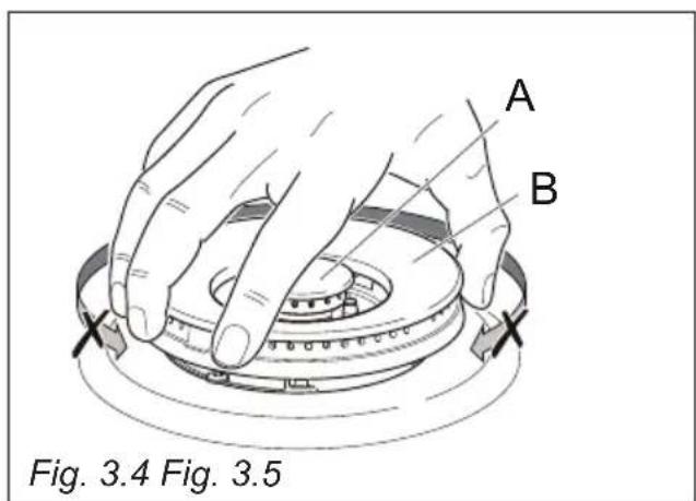
The triple ring burner must be correctly positioned (see fig. 3.5); the burner rib must be enter in their logement as shown by the arrow (see fig. 3.3).
The burner correctly positioned must not rotate (fig. 3.4).
Then position the cap “A” and the ring “B” (figs. 3.4, 3.5).
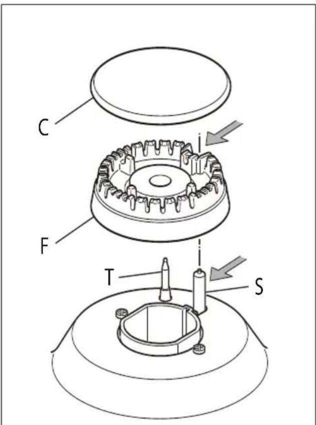
Fig. 3.1 Fig. 3.2
natural_image
Three-step diagram showing a mechanical component with cross marks, no text or symbols present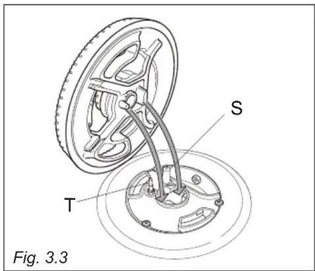
Cher Client
EVACUATION DES PRODUITS DE COMBUSTION
To replace the injectors proceed as follows:
REPLACEMENT DU CÂBLE D'ALIMENTATION
Fig. 1.2a
TABLE ENCASTRABLE "3 FEUX GAZ"
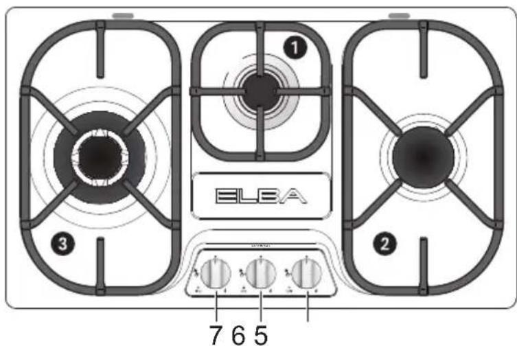
Fig. 1.1b
TABLE ENCASTRABLE "2 FEUX GAZ + 1 PLAQUE ELECTRIQUE"
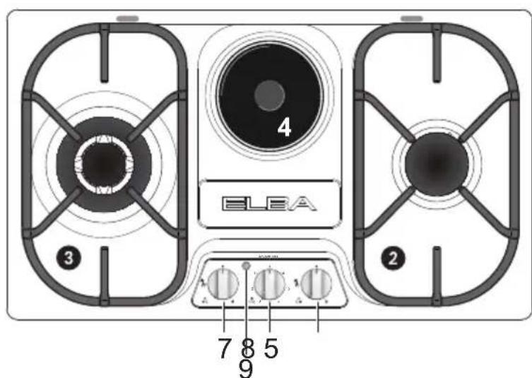
Fig. 1.1c
DESCRIPTION DES FEUX
natural_image
Simple diagram of a droplet inside a circular container with liquid droplets and stars (no text or symbols)Fig. 2.1
natural_image
Simple line drawing of a bag with arrows indicating motion, no text or symbols presentFig. 2.2
natural_image
Line drawing of a cooking pot on a gas stove (no text or symbols)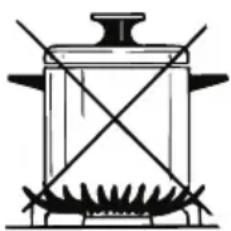
natural_image
Simple line drawing of a cooking pot with two crossed panes and a base (no text or symbols)Fig. 2.3
CHOIX DU BRULEUR
natural_image
Two technical illustrations of a gas stove with labeled components, showing top and side views (no text or symbols on the diagrams themselves)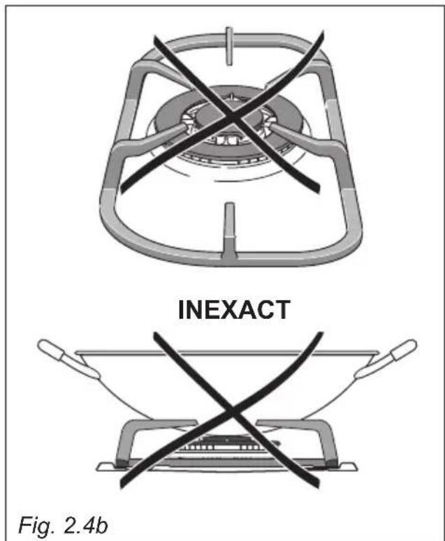
natural_image
Prohibition sign showing a crossed lever over plants, no text or symbols present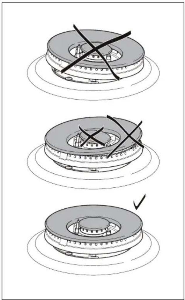
natural_image
Three-step diagram showing a mechanical assembly with cross marks, no text or symbols present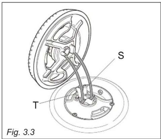
ELBA
TALENT FOR COOKING

Made in Italy
- BUILT-IN COOKING HOBS
- TABLES ENCASTRABLES
- 100% ELBA QUALITY MADE IN ITALY
- ELBA
- English Instructions for the use - Installation advices
- IMPORTANT SAFETY PRECAUTIONS AND RECOMMENDATIONS
- Advice for the installer
- WARNING
- TECHNICAL INFORMATION FOR THE INSTALLER
- CUPBOARD DOORS (fig. 1.3)
- FASTENING THE INSTALLATION BRACKETS (figs. 1.4, 1.5)
- VENTILATION REQUIREMENTS
- DISCHARGING PRODUCTS OF COMBUSTION
- GAS INSTALLATION REQUIREMENTS
- Important!
- OR
- CONNECTING THE COOKTOP TO THE GAS SUPPLY
- ADDITIONAL GAS CONNECTION REQUIREMENTS
- When connecting the cooktop to the gas supply with a rubber hose, make sure that:
- When connecting the cooktop to the gas supply with rigid pipes or a flexible hose, make sure that:
- Some models - for the gas category check the data label attached on the appliance
- LUBRICATION OF THE GAS TAPS
- REPLACEMENT OF THE INJECTORS
- REPLACEMENT OF THE INJECTORS OF THE COOKTOP BURNERS
- SETTING THE MINIMUM OF THE COOKTOP BURNERS
- DETAILS
- POWER SUPPLY CABLE
- FEEDER SPECIAL CABLE SECTION TYPE "H05RR-F"
- Advice for the users
- GAS BURNERS
- CONTROL PANEL DESCRIPTION
- NOTE:
- CAUTION:
- CHOICE OF THE BURNER
- DIAMETERS OF PANS WHICH MAY BE USED ON THE BURNERS
- SPECIAL WOK GRILLE
- Warning:
- IMPORTANT:
- ELECTRIC HOTPLATE (Models with electric hotplate only)
- RAPID HOTPLATE (red dot)
- PROPER USE OF THE ELECTRIC HOTPLATE (fig. 2.6)
- COOKING HINTS
- GENERAL ADVICE
- ATTENTION
- ENAMELLED SURFACES
- STAINLESS STEEL SURFACES
- PAINTED PARTS AND SILKSCREEN PRINTED SURFACES
- GAS TAPS
- HOT PLATE (MODELS WITH CAST IRON ELECTRICAL HOTPLATE ONLY)
- BURNERS AND PAN SUPPORTS
- Warning! Not dishwasher safe.
- CORRECT REPLACEMENT OF THE AUXILIARY AND SEMI-RAPID BURNERS
- CORRECT REPLACEMENT OF THE TRIPLE RING BURNER
- Cher Client
- EVACUATION DES PRODUITS DE COMBUSTION
- REPLACEMENT DU CÂBLE D'ALIMENTATION
- DESCRIPTION DES FEUX
- CHOIX DU BRULEUR
Brand : Elba
Model : Alterum EN74-300 XD
Category : Cooker