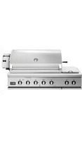
BH1-48RS-N - Barbecue Fisher & Paykel - Free user manual and instructions
Find the device manual for free BH1-48RS-N Fisher & Paykel in PDF.


| Product Type | Outdoor Built-In Gas Barbecue |
| Brand | Fisher & Paykel |
| Model | BH1-48RS-N |
| Dimensions (W x D x H) | 1216 x 676 x 616 mm |
| Total Gas Consumption | 126,500 Btu/h (133.5 MJ/h) |
| Main Burners | 4 stainless steel U-burners (25,000 Btu/h each) |
| Side Burner | 1 burner (included) |
| Rotisserie Burner | Infrared burner |
| Smoker Burner | 3,500 Btu/h (3.7 MJ/h) |
| Ignition | Battery-operated electronic ignition |
| Grease Management System | Grease Management System™ with drip tray |
| Material | Stainless steel |
| Grates | Reversible stainless steel (W-side and rounded side) |
| Radiants | Ceramic rods |
| Rotisserie Motor | Included, 22 kg capacity |
| Gas Pressure (Natural) | 4.0 in. WC |
| Gas Pressure (Propane) | 11.0 in. WC |
| Ignition Battery | Annual replacement recommended |
| Use | Outdoor use only |
| Min. Clearance (Non-Combustible) | 76 mm rear, 153 mm sides recommended |
| Min. Clearance (Combustible) | 457 mm on each side and rear |
Frequently Asked Questions - BH1-48RS-N Fisher & Paykel
User questions about BH1-48RS-N Fisher & Paykel
0 question about this device. Answer the ones you know or ask your own.
Ask a new question about this device
Download the instructions for your Barbecue in PDF format for free! Find your manual BH1-48RS-N - Fisher & Paykel and take your electronic device back in hand. On this page are published all the documents necessary for the use of your device. BH1-48RS-N by Fisher & Paykel.
USER MANUAL BH1-48RS-N Fisher & Paykel
PROFESSIONAL GRILL
36 & 48" BH1 models
LE GRIL PROFESSIONNEL
If the information in this manual is not followed exactly, a fire or explosion may result causing property damage, personal injury or death.
Do not store or use gasoline or other flammable vapors and liquids in the vicinity of this or any other appliance.
WHAT TO DO IF YOU SMELL GAS
- Do not try to light any appliance.
- Do not touch any electrical switch.
- Do not use any phone in your building.
- Immediately call your gas supplier from a neighbor's phone. Follow the gas supplier's instructions.
- If you cannot reach your gas supplier, call the fire department.
Installation and service must be performed by a qualified installer, service agency or the gas supplier.
| Safety and warnings | 3 | |||
| Grill models | 6 | |||
| Product dimensions | 7 | |||
| Installation | ||||
| Locating grill / built-in clearances | 8 | |||
| Built-in construction details | ||||
| Gas hook-up | 14 | |||
| Leak testing | 17 | |||
| Burner adjustment | 18 | |||
| Radiant assembly | 19 | |||
| Installer checklist | 20 | |||
| Using the grill | ||||
| Lighting instructions | 21 | |||
| Grilling | 23 | |||
| Using the smoker system | 29 | |||
| Using the rotisserie | ||||
| Care & maintenance | ||||
| Troubleshooting | 37 | |||
| Service | 38 | |||
Thank you for selecting this DCS Professional BH1 Series Grill. This installation and user guide contains valuable information on how to properly install, operate and maintain your new appliance for years of safe and enjoyable cooking.
Please fill out and submit your Product Registration by visiting our website at www.dcsappliances.com and selecting “Support” on the home page and then selecting “Product Registration”.
For your convenience, product questions can be answered by a DCS Customer Care Representative at www.dcsappliances.com, or email: customer.care@fisherpaykel.com.
Please write the model, code, and serial numbers on this page for reference (can be found on the inside, right side panel behind the drip pan handle. See page 20).
MODEL NUMBER CODE SERIAL NUMBER
IMPORTANT!
DO NOT discard any packing material (box, pallet, straps) until the unit has been inspected. Inspect the product to verify that there is no shipping damage. If any damage is detected, call the shipper and initiate a damage claim. DCS by Fisher & Paykel is not responsible for shipping damage.
To reduce the risk of fire, electrical shock, injury to persons, or damage when using the appliance, follow the important safety instructions listed below:
WARNING!

Hot Surface Hazard
Accessible parts may become hot during use.
Do not touch surface units or areas near units of the grill.
Hood must be opened before lighting the grill.
Never let clothing or other flammable materials come in contact with or get too close to any grate, burner or hot surface until it has cooled. Fabric may ignite and result in fire or personal injury.
Never lean over an open grill. When lighting a burner, always pay close attention to what you are doing. Be certain you are pushing the burner knob when you attempt to light the grill.
When using the grill, do not touch the grill burner, grate, or immediate surrounding area as these areas become extremely hot and could cause burns.
Grease is flammable. Never operate the grill without a grease tray. Let hot grease cool before attempting to handle it. Avoid letting grease deposits collect in the drip pan.
Clean the grill with caution. Avoid steam burns; do not use a wet sponge or cloth to clean the grill while it is hot. Some cleaners produce noxious fumes or can ignite if applied to a hot surface.
Use only dry potholders; moist or damp potholders on hot surfaces may cause burns from steam. Do not use a towel or bulky cloth in place of potholders. Do not let potholders touch hot portions of the grill or burner grate.
To avoid burns when cooking, use long handled BBQ tools.
Failure to follow this advice may result in burns and scalds or serious injury.
WARNING!

Explosion Hazard
If you smell gas, do not use the appliance.
Do not use water on grease fires, a violent steam explosion may result. Turn all burners off, then smother fire or flame or use dry chemical or foam-type extinguisher.
Do not heat unopened food containers such as cans – build-up of pressure may cause container to burst and result in injury.
Failure to follow this advice may result in injury or death.
WARNING!
Fire Hazard
Do not operate the grill under un protected combustible construction. Use only in well ventilated areas. Do not use in buildings, garages, sheds, breezeways, covered structures or other such enclosed areas. This unit is for outdoor use only.
Never leave the grill unattended when in use.
Never store a spare LP cylinder under or near this unit.
Never fill the tank beyond 34 full.
Do not store a full tank in direct sunlight.
Failure to follow this advice may result in death or serious injury.
WARNING!

Electrical Shock Hazard
This appliance (rotisserie motor) is equipped with a three-prong or four-prong grounding plug for your protection against shock hazard and should be plugged directly into a properly grounded power outlet. Do not under any circumstances cut or remove the grounding prong from this plug.
Failure to follow this advice may result in death or electrical shock.
IMPORTANT SAFETY INSTRUCTIONS!
- Children should not be left alone or unattended in an area where the grill is being used. Never allow them to sit, stand or play on or around the grill at any time. When in use, portions of the grill get hot enough to cause severe burns.
- Do not store items of interest to children around or below the grill, in the cart or masonry enclosure. Never allow children to crawl inside a cart or enclosure.
- After a period of storage or non-use (such as over the winter), the gas grill should be checked for gas leaks, deterioration, proper assembly, and burner obstructions before using.
- Do not heat unopened food containers as a build-up of pressure may cause the container to burst.
- Always use a covered hand when opening the grill lid and only do so slowly to allow heat and steam to escape.
- Do not try lighting this appliance without reading the “LIGHTING INSTRUCTIONS” section of this manual (page 21).
• After lighting burners, make sure burners are operating normally (see page 18). - Do not use aluminum foil to line drip pans or grill grates or radiants. This can severely upset combustion air flow or trap excessive heat in the control area. The result of this can be melted knobs or damaged ignition components.
- Do not operate with a damaged cord or plug or after the appliance malfunctions or has been damaged in any manner. Contact the manufacturer for repair.
- Do not let the rotisserie cord hang over the edge of a table or touch hot surfaces.
- Do not use an outdoor cooking appliance for purposes other than intended.
- For personal safety, wear proper apparel. Loose fitting garments or sleeves should never be worn while using this appliance. Some synthetic fabrics are highly flammable and should not be worn while cooking. Only certain types of glass, heat-proof glass ceramic, earthenware, or other glazed utensils are suitable for grill use. These types of materials may break with sudden temperature changes. Use only on low or medium heat settings according to the manufacturer's directions.
- Spiders and insects can nest in the grill burners, causing gas not to flow through the burner. The gas will flow from the front of the burner into the control panel. This is a very dangerous condition which can cause a fire to occur behind the valve panel, thereby damaging the grill components and making it unsafe to operate.
- Keep the area surrounding the grill free from combustible materials, trash, or combustible fluids and vapors such as gasoline, charcoal or lighter fluid. Do not obstruct the flow of combustion and ventilation air.
- Never use the grill in windy conditions. If located in a consistently windy area (oceanfront, mountaintop, etc.) a wind break will be required. Always adhere to the specified clearances as defined in the “INSTALLATION” section of this manual. Refer to the “Grill Placement” section for details if fitting a wind break.
- CALIFORNIA PROPOSITION 65-WARNING: The burning of gas cooking fuel generates some by-products which are on the list of substances which are known by the State of California to cause cancer or reproductive harm. California law requires businesses to warn customers of potential exposure to such substances. To minimize exposure to these substances, always operate this unit according to the manual, ensuring you provide good ventilation when cooking with gas.
- This outdoor cooking gas appliance is not intended to be installed in or on recreational vehicles, trailers and/or boats.
- Note: this product must be installed by a licensed plumber or gas fitter when installed within the Commonwealth of Massachusetts.
- When using the side burners always use flat bottomed pans which are large enough to cover the side burner. Adjust the flame so that it heats only the bottom of the pan to avoid ignition of clothing. Position handles inward away from open edges of the unit to avoid burns associated with unintentional spillovers. Hold the handle of the pan to prevent movement of it when turning or stirring food. For proper lighting and performance of the burners keep the ports clean. It is necessary to clean periodically for optimum performance.
IMPORTANT SAFETY INSTRUCTIONS!
- Be sure all grill controls are turned off and the grill is cool before using any type of aerosol cleaner on or around the grill. The chemical that produces the spraying action could, in the presence of heat, ignite or cause metal parts to corrode.
- Never grill without the drip pan and grease tray in place and pushed all the way to the back of the grill. Without it hot grease could leak downward and produce a fire or explosion hazard.
- Do not place griddle plates (some models only) side by side on the grill or on top of the Infrared Hybrid Burner.
- Do not use the Infrared Hybrid Burner on BGB-36" or BGB-48" models. Use on BH1-36" & BH1-48" models only.
- If a cart unit is stored indoors, ensure that it is cool, fold the side shelf down, then push the grill, never pull. Never push or pull on the side shelves. If LP, the cylinder must be unhooked and the LP cylinder stored outside in a well ventilated area, out of reach of children.
- Never use the grill in a windy area.
- Do not locate, store or operate the grill on an inclined plane. Make sure you lock the castor wheels before operating the grill.
- Do not use charcoal or lighter fluid in the outdoor grill.
- Keep any electrical supply cord, or the rotisserie motor cord away from the heated areas of the grill and water (pools, fountains, puddles).
- Never use a dented or rusty LP tank. Keep the ventilation openings of the cylinder enclosure free and clear from debris.
- Do not move the appliance during its use.
- This unit is for outdoor use only. Do not operate in enclosed areas. This could result in carbon monoxide build-up which would result in injury or death.
- When using a grill, be sure that all parts of the unit are firmly in place and that the grill is stable (can't be tipped over).
- To put out flare-ups, adjust the controls to lower the temperature
- Never attach or disconnect an LP cylinder, or move or alter gas fittings when the grill is in operation or is hot.
- Clean and perform general maintenance on the grill twice a year. Watch for corrosion, cracks, or insect activity. Check the regulator, hoses, burner ports, air shutter, and venturi/valve section carefully. Always turn off gas at the source (tank or supply line) prior to inspecting parts.
- If you own or use a spare tank, or have a disconnected tank, you should NEVER store it near or under the grill/cart unit or heat box, or near any other ignition or heat source. A metallic sticker with this warning is provided with the grill to remind you, your family and all others who may use your BBQ grill of these safety precautions. Install this sticker close to your barbeque grill.
DANGER
NEVER store a spare LP cylinder under or near this unit.
NEVER fill the tank beyond 3/4 full.
A fire causing death or serious injury may occur.
P/N 17147 Rev. 8
Sticker
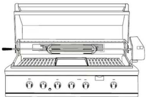
natural_image
Line drawing of a portable electric stove with open lid and control knobs (no text or symbols)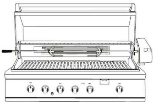
natural_image
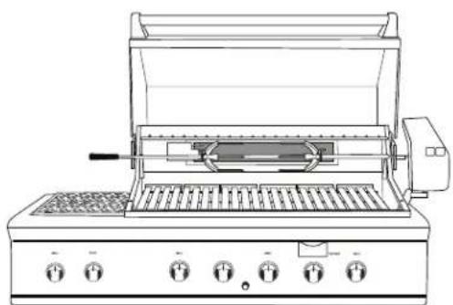
Line drawing of a portable electric grill with control knobs and grilles (no text or symbols)BH1-48RBH1-48RGI
natural_image
Line drawing of a portable electric grill with control knobs and grilles (no text or symbols)BH1-48RS
natural_image
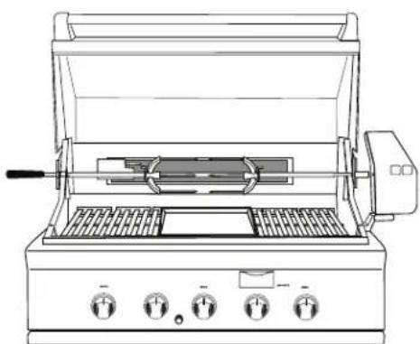
Line drawing of a portable electric stove with control knobs and grilles (no text or symbols)BH1-36RGI

natural_image
Line drawing of a portable electric stove with grating and control knobs (no text or symbols)BH1-36R
natural_image
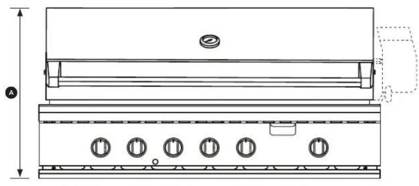
Technical line drawing of a portable stove or oven unit with five circular vented slots and a side door (no text or labels)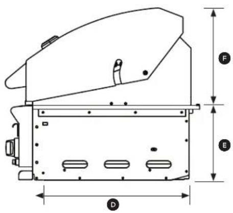
BH1-48RGI Model Illustrated
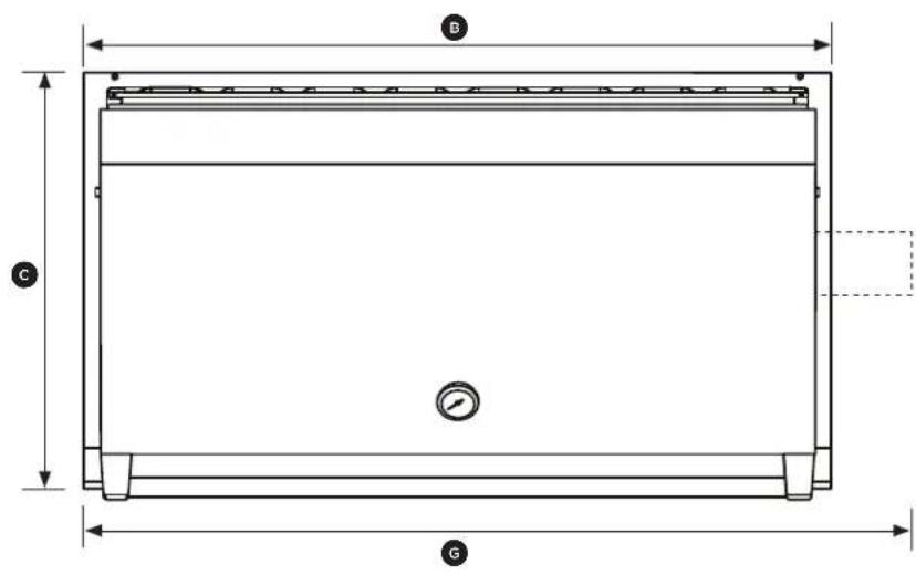
| PRODUCT DIMENSIONS | BH1-48RS | BH1-48/RGI BH1-36/RGI | ||
| INCHES (MM) | INCHES (MM) INCHES (MM) | |||
| A | Overall height of grill | 24 1/4 (616) | 24 1/4 (616) 24 1/4 (616) | |
| B | Overall width of grill | 47 7/8 (1216) | 47 7/8 (1216) 35 7/8 (911) | |
| C | Overall depth of grill(excluding handle and dials) | 26 5/8 676 | 26 5/8 676 26 5/8 676 | |
| D | Depth of chassis | 22 5/16 (567) | 22 5/16 (567) 22 5/16 (567) | |
| E | Height of chassis | 10 (254) | 10 (254) 10 (254) | |
| F | Height of hood | 13 3/4 (349) | 13 3/4 (349) 13 3/4 (349) | |
| G | Overall width of grill withrotisserie motor mounted | 53 7/16 (1357) | 53 1/4 (1352) 41 5/8 (1057) | |
Locating Grill/Built-in Clearances
IMPORTANT!
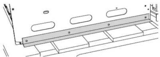
Before installation, remove shipping brackets from the grill. Loosen the four screws. Slide the shipping bracket off and re-tighten the screws.
natural_image
Technical line drawing of a mechanical assembly with no visible text or symbolsLocation
When determining a suitable location, take into account concerns such as exposure to wind, proximity to traffic paths and keeping any gas or electrical supply lines as short as possible and away from heat sources. Locate the grill only in a well ventilated area. Do not build the grill under overhead unprotected combustible construction. Never locate the grill in a building, garage, breezeway, shed or other such enclosed areas. During heavy use, the grill will produce a lot of heat and smoke. Ensure that the grill is used in a well ventilated area.
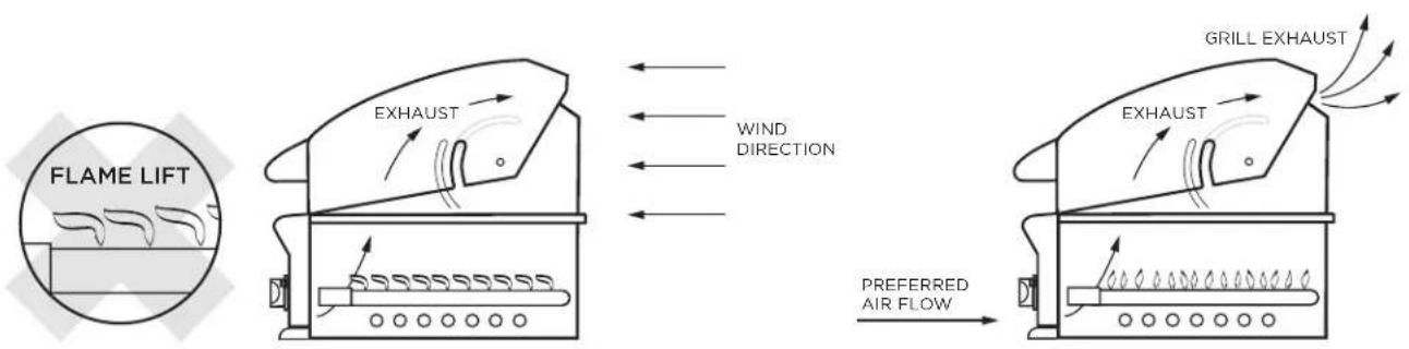
If locating the grill in a windy area, try to locate the grill so the prevailing wind will blow air at the front of the grill as shown in Fig. 01b. This will assist the grill in venting hot air through the back of the grill. In addition, this will help keep any smoke from blowing at someone who is cooking on the grill. If you have to locate the grill in a windy area where the prevailing wind is at the rear of the grill (Fig. 01a), a windscreen must be installed. The windscreen should be set-up so that it blocks wind from entering the exhaust vent in the rear of the unit as shown in Fig. 01c. Location of the windscreen relative to rear of the grill must adhere to the clearances specified for combustible or non-combustible construction as defined in these instructions. Refer to following pages.
As a high-performance gas appliance, your grill requires significant amounts of air to support the combustion process. Your grill is designed to take air in through the valve panel area, and send the exhaust products out through the exhaust gap at the rear of the hood. Using your grill in windy conditions can disrupt the proper flow of air though your grill, leading to reduced performance, or in certain severe cases, causing heat buildup in the valve panel area. This can lead to problems such as having the knobs melt, or burn hazards when the valve panel surfaces become too hot to touch.
Please note that damage to your grill resulting from use in windy conditions, such as melted knobs or igniter wires, or valve panel discoloration from heat build-up, are excluded from warranty coverage.
Locating Built-in Clearances
IMPORTANT!
Gas fittings, regulator, and installer supplied shut-off valves must be easily accessible.
flowchart
graph LR
    A["FLAME LIFT"] --> B["EXHAUST"]
    B --> C["Wind DIRECTION"]
    C --> D["GRILL EXHAUST"]
    D --> E["PREFERRED AIR FLOW"]
    style A fill:#f9f,stroke:#333
    style B fill:#ccf,stroke:#333
    style C fill:#cfc,stroke:#333
    style D fill:#fcc,stroke:#333
    style E fill:#ffc,stroke:#333
FIG. 01a FIG. 01b
Wind hitting the grill while in use, (especially wind blowing into or across the hood gap) can cause poor performance and in some cases can cause the control panel to get dangerously hot.
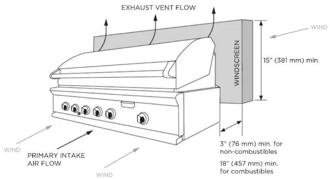
FIG. 01c
If wind is an issue, a windscreen should be added. The windscreen should be higher than the top of the opening in the back of the grill, with a minimum clearance of 3" (76mm) for non-combustibles, or 18" (457mm) for combustibles, from the back of the grill.
Locating Built-in Clearances
Clearances to non-combustible construction\*
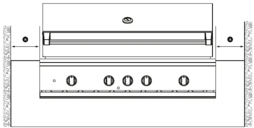
A minimum of 3" clearance from the back of the grill to non-combustible construction is required for the purpose of allowing the lid to open fully. It is desirable to allow at least 6" rear and side clearance to non-combustible construction above the cooking surface for counter space. If you'll be using the rotisserie option, the space is essential for motor and skewer clearance. The grill can be placed directly adjacent to non-combustible construction below the cooking surface (Fig. 02).

natural_image
Technical line drawing of a two-view electrical enclosure showing top and side views with no text or symbolsFIG. 02
PRODUCT DIMENSIONS INCHES (MM)
Ⓐ Minimum distance from non-combustible surface to grill
3 (76)


NON-COMBUSTIBLE SURFACE
*DEFINITION OF NON-COMBUSTIBLE MATERIAL - Material which is not capable of being ignited and burned, such as materials consisting entirely of, or a combination of, steel, iron, brick tile, concrete, slate, and plaster.
IMPORTANT!
- Failure to maintain required clearances creates a fire hazard that may result in property damage or serious personal injury.
- The grill is designed to function in an open area. Recommended minimum clearances should be maintained to all surfaces (combustible and non-combustible) for optimum performance. Non-combustible material within the minimum clearance area could result in discoloration or deterioration.
- If a non-combustible material such as stucco is covering a combustible material such as wood, the minimum clearance distance needs to be considered for wood. The presence of a non-combustible material inside the clearance zone does not eliminate the minimum clearance zone to combustible material.
General
The grill is designed for easy placement into built-in masonry enclosures. For non-combustible applications the grill drops into the opening shown in Fig. 04 and hangs from its side flanges. A deck is not required to support it from the bottom. When using the insulated jacket in a combustible enclosure application, see the Fig. 05. The insulation jacket assembly must be supported from the bottom by a ledge on each side and back or a solid deck.
A spirit level should be used to ensure that the unit is level both front-to-back and side-to-side. If it is not level, burner combustion may be erratic or the unit may not function efficiently for grease flow. If the floor is uneven, re-leveling may be required whenever a freestanding unit is moved.
Locating Built-in Clearances
Clearances to combustible construction\*\*
Minimum of 18" (457 mm) from the sides and rear of grill must be maintained to adjacent vertical combustible construction, above the counter top level. You should take in account that there is a large volume of heat, and smoke will exhaust from the rear of the grill. This may discolor or damage unprotected areas. Do not install under unprotected combustible construction without using a fire safe ventilation system.
A 18" (457mm) minimum clearance must be maintained under the counter top to combustible construction. The clearance can be modified by a use of an insulated jacket.
natural_image
Technical line drawing of a mechanical assembly with labeled components (no text or symbols)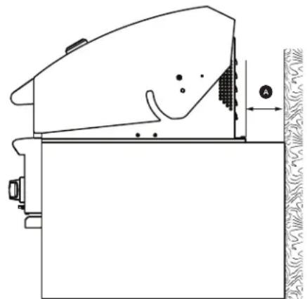
natural_image
Technical line drawing of a mechanical component with no visible text or symbolsFIG. 03
PRODUCT DIMENSIONS INCHES (MM)
| A | Minimum distance from combustible surface to grill |
18 (457)

COMBUSTIBLE SURFACE
**DEFINITION OF COMBUSTIBLE MATERIAL - Any materials of a building structure or decorative structure made of wood, compressed paper, plant fibers, vinyl/plastic or other materials that are capable of transferring heat or being ignited and burned. Such material shall be considered combustible even though flame-proofed, fire-retardant treated or surface-painted, or plastered.
IMPORTANT!
It is recommended that a minimum of two 12 1/4x12 1/4" (311 x 311mm) vents be provided in order to safely dissipate unburned gas vapors in the event of a gas supply leak. These are to be located on each side of the enclosure and within 5" (127mm) of the top.
Insulated jacket
If the grill is to be placed into a combustible enclosure, an approved insulated jacket is necessary. Insulated jackets are available from your dealer. Use only the DCS insulated jacket which has specifically been designed and tested for this purpose. Review the detail drawing shown (Fig. 05) and take into account the provisions shown for gas line hook-up clearance in the right rear corner. It is required that ventilation holes are provided in the enclosure to eliminate the potential build-up of gas in the event of a gas leak. The supporting ledges or deck must be level and flat and strong enough to support the grill and insulated jacket. The counter should also be level.
IMPORTANT!
Installing this product into a combustible enclosure without an insulated jacket could result in fire, property damage and personal injury.
Built-in Construction Details
Standard layout for non-combustible cavity
IMPORTANT!
If installing the grill into a non-combustible enclosure, all combustible construction must still be outside the 18" (457mm) clearance zone. If your island is made of stucco over the top of wooden studs, the wood can not be inside the 18 inch clearance zone to combustible, even though the stucco is what is touching the grill area.
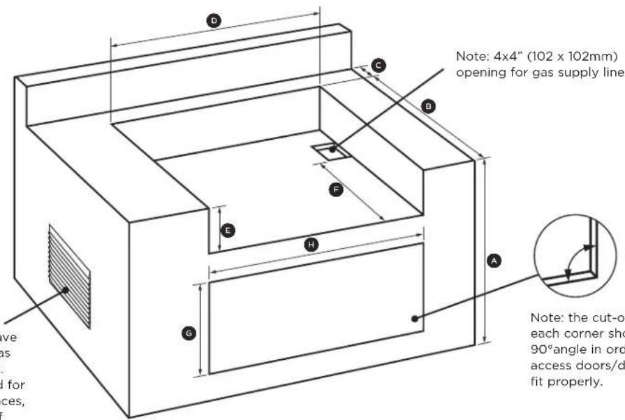
Note: The enclosure should have ventilation holes to prevent gas build-up in the event of a leak. Refer to ANSI Z21.58 Standard for Outdoor Cooking Gas Appliances, Section 1.7 Enclosures For Self Contained LP-Gas Supply Systems.
Note: the cut-out of each corner should be a 90° angle in order for the access doors/drawers to fit properly.
FIG. 04
| CAVITY DIMENSIONS | BH1-48R BH1-36R | ||
| Inches (mm) | Inches (mm) | ||
| A | Maximum height of enclosure shell | 35 1⁄2 (902) | 35 1⁄2 (902) |
| B | Depth of enclosure shell | 22 3⁄4 (578) | 22 3⁄4 (578) |
| C | Minimum depth for hood swing | 3 3⁄4 (95) | 3 3⁄4 (95) |
| D | Width of enclosure cavity | 45 3⁄4 (1162) | 34 1⁄2 (876) |
| E | Height of enclosure cavity | 10 1⁄8 (257) | 10 1⁄8 (257) |
| F | Depth to gas supply opening | 18 1⁄2 (470) | 18 1⁄2 (470) |
| G | Height of opening for access doors/drawers | 20 (508) | 20 (508) |
| H | Width of opening for access doors/drawers | 46 (1168) | 34 (864) |
Built-in Construction Details
Standard layout for cavity including insulated jacket
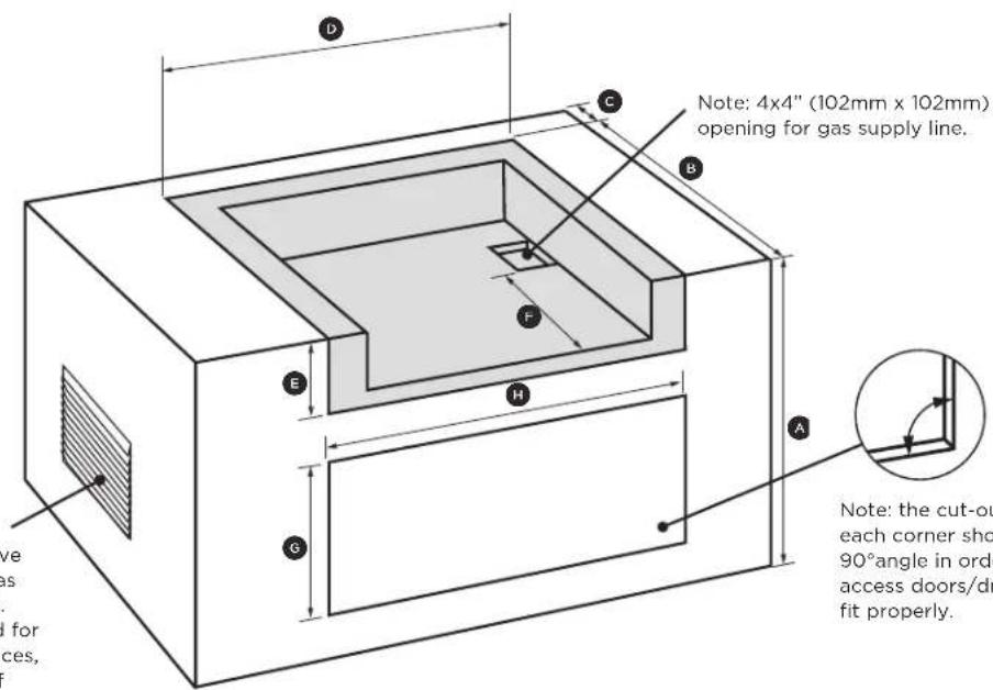
Note: the enclosure should have ventilation holes to prevent gas build-up in the event of a leak. Refer to ANSI Z21.58 Standard for Outdoor Cooking Gas Appliances, Section 1.7 Enclosures For Self Contained LP-Gas Supply Systems.
FIG. 05
| CAVITY DIMENSIONS | BH1-48R BH1-36R | ||
| Inches (mm) | Inches (mm) | ||
| A | Maximum height of enclosure shell | 35 1⁄2 (902) | 35 1⁄2 (902) |
| B | Depth of enclosure shell | 23 3⁄4 (603) | 23 3⁄4 (603) |
| C | Minimum depth for hood swing | 18 3⁄4 (476) | 18 3⁄4 (476) |
| D | Width of enclosure cavity | 51 5⁄8 (1318) | 40 1⁄2 (1029) |
| E | Height of enclosure cavity | 11 1⁄8 (283) | 11 1⁄8 (283) |
| F | Depth to gas supply opening | 18 1⁄2 (470) | 18 1⁄2 (470) |
| G | Height of opening for access doors/drawers | 20 (508) | 20 (508) |
| H | Width of opening for access doors/drawers | 46 (1168) | 34 (864) |
| ACCESS DOORSMODEL NUMBER | ACCESS DRAWERSMODEL NUMBER | CAVITY WIDTH CAVITY HEIGHT | |
| Inches (mm) | Inches (mm) | ||
| ADN1-20x48 ADR2-48 | 46 (1168) | 20 (508) | |
| ADN1-20x36 | ADR2-36 | 34 (864) | 20 (508) |
| ADN1-20x30 | ADR2-30 | 28 (711) | 20 (508) |
| ADN1-20x24 | ADR2-24 | 22 (559) | 20 (508) |
To order access drawers or doors, please visit www.dcsappliances.com for further details.
Gas Hook-up
Gas requirements
Verify the type of gas supply to be used, either natural or LP, and make sure the marking on the appliance rating plate agrees with that of the supply. The rating plate is located on the underside of the drip tray. Never connect an unregulated gas line to the appliance. You must use the gas regulator provided with the unit, even if the supply is controlled.
An installer-supplied gas shut-off valve must be installed in an easily accessible location. All installer supplied parts must conform to local codes, or in the absence of local codes, with the National Electrical Code, ANSI/NFPA 70 or the Canadian Electrical Code, CSA C22.1, and the National Fuel Gas Code, ANSI Z223.1 or CSA-B149.1 Natural Gas Installation Code or CSA-B149.2 Propane Installation Code. In Massachusetts such shut-off valves should be approved by the Board of State Examiners or Plumbers & Gas Fitters.
All pipe sealants must be an ap proved type and resistant to the actions of LP gases. Never use pipe sealant on flare fittings. All gas connections should be made by a qualified technician and in accordance with local codes and ordinances. In the absence of local codes, the installation must comply with the National Fuel Gas Code ANSI Z223.1. Gas conversion kits are available from Customer care. When ordering gas conversion kits, have the model number, and the type of gas (natural or LP) from your grill.
Total gas consumption of the grill with all burners on HI
BH1-48RS - 126,500 Btu/hr or 133.5MJ/h BH1-48R/BH1-48RGI - 121,500 Btu/hr or 128.2 MJ/h BH1-36R/BH1-36RGI - 92,500 Btu/hr or 97.5 MJ/h.
The appliance and its individual shut-off valve must be disconnected from the gas supply piping system during any pressure testing of that system at test pressures in excess of 1/2 PSIG (3.5 kPa.) The appliance must be isolated from the gas supply piping system by closing its individual manual shut-off valve during any pressure testing of the gas supply piping system at test pressures equal to or less than 1/2 PSIG (3.5 kPa.). The installation of this appliance must conform with local codes or, in the absence of local codes, with the National Fuel Gas Code, ANSI Z223.1/NFPA 54. Installation in Canada must be in accordance with Natural Gas and Propane Installation Code, CSA B149.1, and/or Propane Storage and Handling Code, B149.2 and local codes.
Natural gas built-in hook-up
(This should be performed by a technician only)
Connection: 1/2" NPT female with 3/8" flare adapter
Operating pressure: 4.0" W.C. Supply pressure:
5" to 14" WC. If in excess of 14" W.C., a step down regulator is required. Check with your local gas utility company or local codes for instructions on installing gas supply lines. Be sure to check on type and size of run, and how deep to bury the line. If the gas line is too small, the grill will not function properly. Any joint sealant used must be an approved type and be resistive to the actions of LP gases.
To hook-up the fittings supplied with the grill
Assemble as shown (Fig. 06). Use threading compound on male threads only. Do not use threading compound on the male end of the 1/2 NPT to 3/8 flare adapter. Use a second pipe wrench to hold the grill inlet pipe to avoid shifting any internal gas lines of the grill. Ensure that the regulator arrow points in the direction of gas flow towards the unit, away from the supply. Do not forget to place the installer-supplied gas valve in an accessible location.
LP Gas Hook Up (Type 1 or QCC1 regulator)
Grills orificed for use with LP gas come equipped with a high capacity hose/regulator assembly for connection to a standard 20 lb. LP cylinder (Type 1). The LP tank is not included.
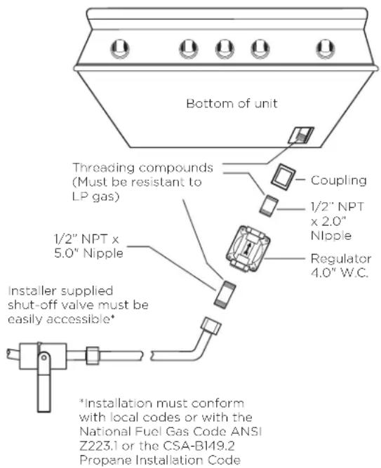
FIG. 06 Natural Gas
Gas Hook-up
LP cart hook-up
Grills orificed for use with LP gas come equipped with a high capacity hose/regulator assembly for connection to a standard 20 lb. LP cylinder (Type 1). The LP tank is not included. The grill system is leak tested, do not remove the Regulator/Hose assembly from the grill during cart installation.
Connection: LP Hose with a Type 1 quick disconnect and regulator is included. Operating pressure: 11.0" W.C. Note: all gas piping and connectors must conform to the Standard for Connectors for Outdoor Gas Appliances and Manufactured Homes, ANSI Z21.75/CSA 6.27.
To connect the LP regulator/hose assembly to the tank/valve assembly, first make sure the main valve on the tank is completely closed. Although the flow of gas is stopped when the Type 1 system is disconnected as part of its safety feature, you should always turn off the LP tank main valve (Fig. 07) after each use and during transport of the tank or unit. Insert the regulator inlet into the tank valve and turn to the black coupler clockwise until the coupler tightens up. Do not overtighten the coupler. Turn the main tank valve on and turn the burner control valves on the unit to the "HI" position for about 20 seconds to allow the air in the system to purge. Turn valves off and wait 5 minutes before attempting to light the burners.
To disconnect the coupler, first make sure the main tank valve is turned off. Grasp the coupler and turn counter clockwise. The inlet will then disengage. Remove the inlet from the tank valve opening if it has not already done so when it disengaged. Your local LP filling station should be equipped with the proper equipment to fill your tank.
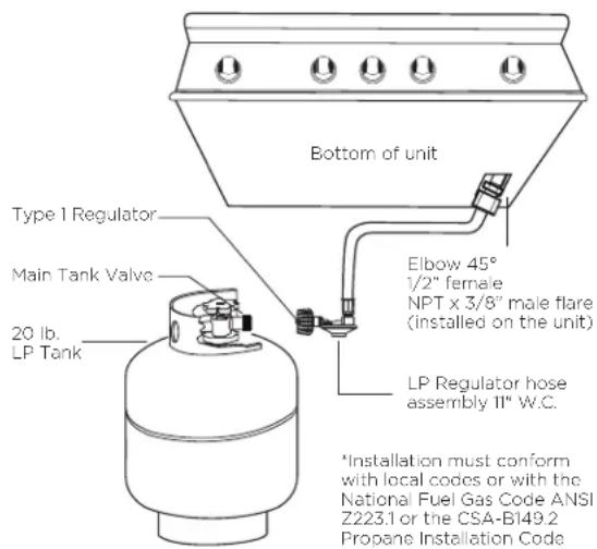
FIG. 07 LP Gas - Cart
IMPORTANT!
- Before connecting LP tank to regulator, check that all grill burners and rotisserie valves are in the OFF position and open grill hood.
- Do not place the Grill directly on the ground or any other flat surface without support. This will prevent damaging the regulator/hose assembly by the weight of the grill.
- Check the hose, regulator and connectors for damage. Look for cracks, abrasions, brittleness, holes, dents and nicks.
- Do not attempt to remove, repair, or replace the regulator/hose assembly by yourself. It must be done by a qualified licensed technician only.
LP tank requirements
A dented or rusty LP tank may be hazardous and should be checked by your LP supplier. The cylinder that is used must have a collar to protect the cylinder valve. Never use a cylinder with a damaged valve. Always check for leaks after every LP tank change. The LP gas cylinder must be constructed and marked in accordance with the specifications for LP gas cylinders of the U.S. Department of Transportation (DOT or CAN/CSA-B339) and designed for use with a Type 1 system only. Do not change the regulator/hose assembly from that supplied with the unit or attempt to use a Type 1 equipped regulator/hose assembly with a standard 510 POL tank/valve assembly. The cylinder must be provided with a shut-off valve terminating in an LP gas supply cylinder valve outlet specified, as applicable, for connection Type 1. If the appliance is stored indoors, the cylinder must be disconnected and removed from the appliance. Cylinders must be stored outdoors in a well-ventilated area out of the reach of children.
Gas Hook-up
LP built-in hook-up
If the grill is to be installed in a built-in application, then the grill must be installed in accordance with the built-in installation guidelines and the LP regulator/hose assembly must be removed from the product.
Connection: LP Hose with a Type 1 quick disconnect and regulator is included. Operating pressure: 11.0" W.C. All gas piping and connectors must conform to the Standard for Connectors for Outdoor Gas Appliances and Manufactured Homes, ANSI Z21.75/CSA 6.27.
If you intend to operate your built-in grill on LP gas utilizing a 20v lb type 1 cylinder, then a built-in LP tank restraint must be installed prior to initial use of the grill. The Installer must supply 12 " ID Flex hose and fixed pipe and a flare adaptor as indicated in Fig. 08.
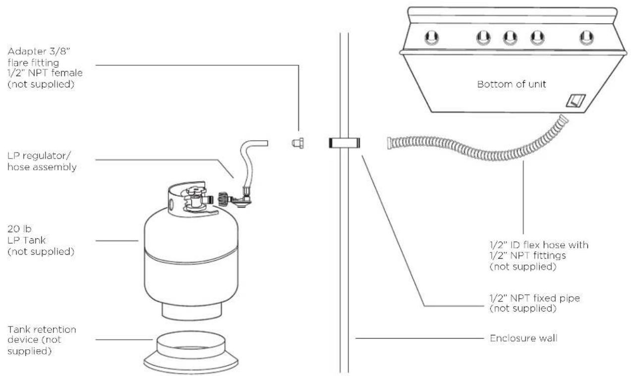
FIG. 08 LP Gas - Built-in
Note: when an LP unit is being directly connected to an LP house system, you must follow the natural gas hook up guidelines.
The installer must provide the proper gas regulator to reduce the gas pressure to 11" W.C.
IMPORTANT!
Gas piping and connectors must be clamped within the enclosure to avoid contact with moving parts and hot surfaces. Where the gas piping passes through an opening in the enclosure, the piping must be protected for a distance of at least 2" (50mm) either side of the opening.
Leak Testing
IMPORTANT!
Gas leak testing must be carried out by a qualified technician.
General
Although all gas connections on the grill are leak tested at the factory prior to shipment, a complete gas tightness check must be performed at the installation site due to possible mishandling in shipment, or excessive pressure unknowingly being applied to the unit. Periodically check the whole system for leaks, or immediately check if the smell of gas is detected.
Before Testing
Do not smoke while leak testing. Extinguish all open flames. Never leak test with an open flame.
Make a soap solution of one part liquid detergent and one part water. You will need a spray bottle, brush, or rag to apply the solution to the fittings. For LP units, check with a full cylinder. The valve panel must be removed to check the valves and fittings. Remove the knobs and the safety valve knob, then remove the 2 screws which fasten the valve panel to the unit (you will need a Philips screw driver for this). Pull the valve panel outward and unplug the wires from the ignition module. In the back of the unit remove the screws which hold the service panel in place. Remove the service panel.
To Test
Make sure all control valves are in the "OFF" position. Turn the gas supply "ON". Check all connections from the supply line, or LP cylinder up to and including the manifold pipe assembly. Apply the soap solution around the connection, valve, tubing and end of the manifold. Avoid getting the soap solution on or in the valve switches. Soap bubbles will appear where a leak is present. If a leak is present, immediately turn off gas supply, tighten any leaking connections, turn gas on, and recheck. Check all the gas connections at the base of the control valves where they screw into the manifold pipe.
To check rotisserie burner and safety valve the burner must be lit, then leak test the connections located behind the service panel. If you cannot stop a gas leak turn off the gas supply and call your local gas utility, or the dealer you purchased the appliance from. Only those parts recommended by the manufacturer should be used on the grill. Substitution can void the warranty.
IMPORTANT!
- Do not use the grill until all connections have been checked and do not leak.
- Check all gas supply fittings for leaks before each use. Keep a spray bottle of soapy water near the gas supply shut-off valve. Spray all the fittings, bubbles indicate leaks.
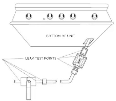
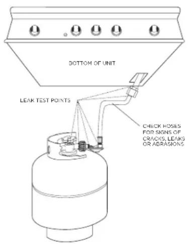
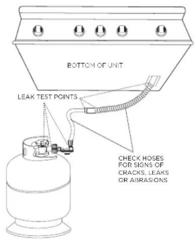
FIG. 10 LP Gas - CartFIG. 09 Nat. Gas FIG. 11 LP Gas - built-in
Burner Adjustment
IMPORTANT!
Before lighting, inspect the gas supply piping or hose prior to turning the gas "on". If there is evidence of cuts, wear, or abrasion, it must be replaced prior to use.
Grill burner air adjustment
Each grill burner is tested and adjusted at the factory prior to shipment; however, variations in the local gas supply or a conversion from one gas to another may make it necessary to adjust the burners. The flames of the burners (except the rotisserie burner) should be visually checked and compared to that of the drawing in Fig.12. Flames should be blue and stable with no yellow tips (LP units may have some yellow tipping), excessive noise or lifting. If any of these conditions exist, check if the air shutter or burner ports are blocked by dirt, debris, spider webs, etc. Proceed with air shutter adjustment. The amount of air which enters a burner is governed by a metal cup at the inlet of the burner called an air shutter. It is locked in place by a screw which must be loosened prior to lighting the burner for adjustment.
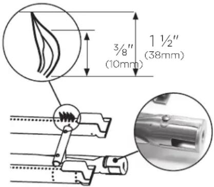
FIG. 12
Grill burner flame height
Before beginning, ensure the grill is off and cool. To access the grill burner air shutters, first remove the grates and radiants from the firebox, then remove the grill burner using instructions shown on page 35. With a screw driver, loosen the lock screw on the face of the air shutter slightly so that the air shutter can be adjusted.
To adjust
① Be careful as the burner may be very hot.
② If the flame is yellow, indicating insufficient air, turn the air shutter counter-clockwise to allow more air to the burner.
③ If the flame is noisy and tends to lift away from the burner, indicating too much air, turn the air shutter clockwise.
Note: reinstall the U-burner, ensuring the burner is level. Light the burner and check the flame. If the color of the flame is blue and the height is stable, remove the burner and tighten the air shutter screw. If the flames show instability or an inconsistent color, repeat the above procedure to readjust the air shutter.
Low flame setting adjustment
The valves on the grill feature an adjustable low setting. Due to fluctuations in gas pressure, heating value or gas conversion, you may feel it necessary to increase or decrease gas flow in the low position. We do not recommend adjusting the infrared rotisserie burner.
To adjust
① Light the burner.
② Turn the control knob to the lowest setting (counter-clockwise).
③ Remove the knob.
④ While holding the valve shaft with pliers, insert a thin, flat tipped screwdriver into the shaft and while viewing the burner adjust to a minimum stable flame.
Side burner flame height
The correct height of the flame mainly depends on the size of the bottom of the cooking utensil, the material of the cooking utensil, the amount and type of food and the amount of liquid in the utensil. Following are some basic rules for selecting flame height.
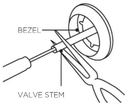
FIG. 13
- For safety reasons the flame must never extend beyond the bottom of the cooking utensil. Never allow flames to curl up the side of the pan.
- Utensils which conduct heat slowly (such as glass-ceramic) should be used with medium to low flames. If you are cooking with a large amount of liquid, a slightly larger flame can be used.
Radiant Assembly
IMPORTANT!
Before assembling the radiant, check that the radiant trays have not moved during transit. They should sit securely on their locating pins in the base of the grill.
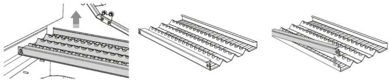
① Locate the radiant in the unit. ③②Unloplack radiation and drop and remove radiant from the unit.
by pushing it up with two fingers.
natural_image
Technical line drawing of a mechanical component with ribbed structure and mounting bracket (no text or symbols)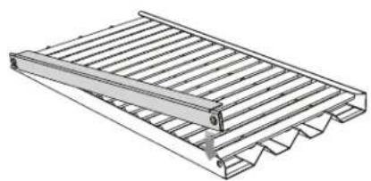
natural_image
Technical line drawing of a metal grate structure with slats and wavy base (no text or symbols)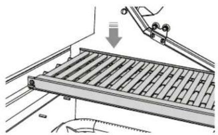
natural_image
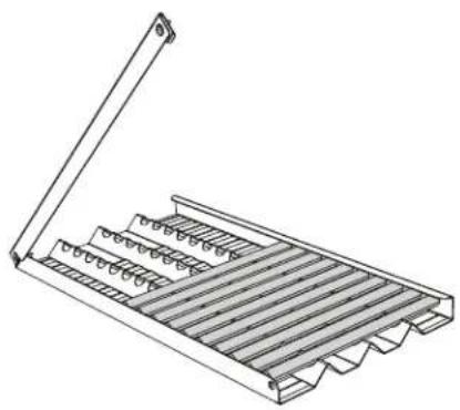
Mechanical assembly diagram showing a conveyor belt system with a hand operating it (no text or symbols present)④ Place the 18 ceramic rods onto the radiant.
⑤ Lock radiant end cap. ⑥ Place the assembled radiant into the unit.
If a ceramic rod breaks
① Unlock radiant end cap by pushing it up with two fingers.
② Replace broken ceramic rod.
③ Lock radiant end cap.
To order a replacement ceramic rod, please visit www.dcsappliances.com.
Note: for BH1-48RGI and BH1-36RGI models see the Quick Start Guide for information on installing the griddle and Infrared Hybrid Burner.

Installer Checklist
□ Specified clearances maintained to combustibles.
□ Verified proper enclosure ventilation.
☐ All internal packaging and any adhesive residue removed. To remove stubborn residue, use rubbing alcohol or a commercially available adhesive remover.
□ Removed shipping bracket.
□ Knobs turn freely, bezels centered.
☐ Each burner lights satisfactorily - individually or with adjacent burner lit.
☐ Air shutters adjusted.
□ Low flame setting satisfactory.
☐ Drip pan in place properly and sliding freely.
Pressure regulator connected and set for 4.0" C.E. Natural, 11.0" C.E. LP gas.
☐ Manual shut-off valve installed and accessible.
☐ Unit tested and free of leaks.
☐ User informed of gas supply shut-off valve location.
☐ All radiant trays are assembled and put in place.
□ Check match lighting.
☐ Please leave these instructions with the user.
□ User, please retain these instructions for future reference.
Contact DCS at www.dcsappliances.com if any of the listed items are missing. Please be prepared with your model #, serial # and description of item(s) that are missing.
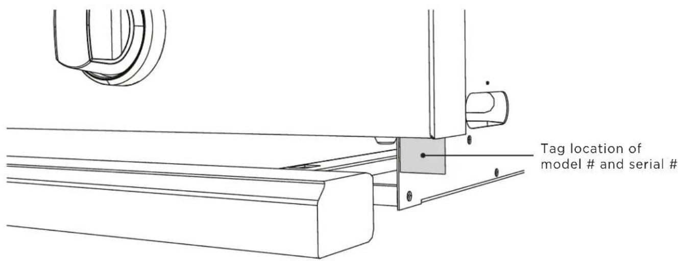
IMPORTANT!
Read all installation instructions in this manual to see if the unit has been correctly installed. Ensure that installation has been completed correctly before use.
Lighting Instructions
Grill lighting instructions
IMPORTANT!
Open the grill lid and/or remove the top grate cover from side burner (for BH1-48RS) before lighting. Turn all knobs to "OFF". Turn the main gas supply on. If you smell gas, shut-off gas supply and call for customer care.
Grill lighting instructions
The grill knob is connected to the electronic ignition module. Pushing in on the burner knob will activate the ignition module to get a spark. Push in and turn the selected burner knob to HI/SEAR position. Release the knob when the burner lights. If burner does not light in four to five seconds, turn knob "OFF" and wait five minutes before trying again so any accumulated gas may dissipate.
Grill Match Lighting
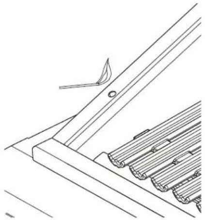
If the burner will not light after several attempts, then the burner can be match lit. If you've just attempted to light the burner with the ignition, allow five minutes for any accumulated gas to dissipate. Keep your face as far away from the outdoor appliance as possible and hold a paper book match over the hole located on the top left for burner on the left, or the right hole for the right burner (Fig. 13). Push in and turn the control knob which is centered on the burner where the lit match is located, to "SEAR". If the burner does not light in four seconds, turn the knob off, wait five minutes and try again.
natural_image
Technical line drawing of a structural component with ribbed and angled elements (no text or symbols)FIG. 14
IMPORTANT!
Improper lighting procedures can cause the LP tank flow control to activate, resulting in reduced heat output. If this is suspected the flow control will need to be reset. For BH1-48RGI and BH1-36RGI models see the Quick Start Guide for how to use the griddle and Infrared Hybrid Burner.
Resetting the flow control
IMPORTANT!
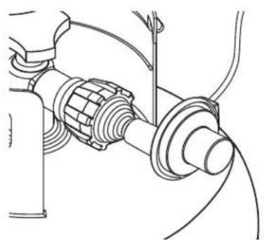
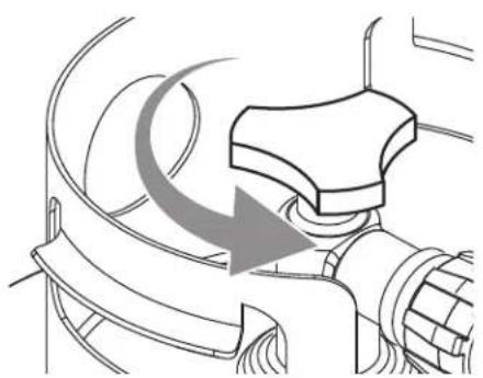
Failure to follow the steps in the order shown may cause the Flow Limiting Device to activate resulting in extremely low gas flow and irregular operation.
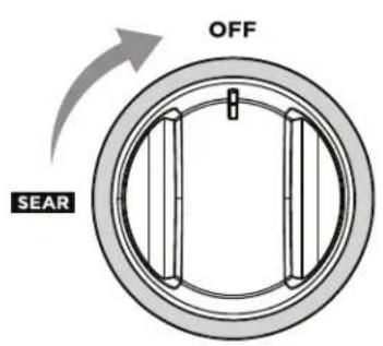
① All knobs must be in the OFF position.
natural_image
Technical line drawing of a mechanical assembly with hoses and connectors (no text or symbols)② Attach regulator hose assembly to the tank.
natural_image
Diagram of a mechanical component with curved arrows indicating motion or force direction (no text or symbols)③ Open the LP tank valve. (Two full turns min).
Lighting Instructions
To Light Dual Side Burners (48BQR Models only)
IMPORTANT!
The side burner cover may be hot if the grill burners are in operation.
Side Burners Lighting Instructions
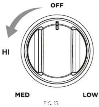
First remove the burner cover and any cooking utensils from the burner grate. The control knob is connected to the electronic ignition module. Pushing in on the control knob will activate the ignition module to get a spark. Push the control knob in and turn to "HI". If burner does not light in four to five seconds, turn knob "OFF" and wait five minutes before trying again for any accumulated gas to dissipate. If the burner will not light after several attempts, check the trouble shooting instructions on page 37.
Side Burners Match Lighting
Hold a lit paper book match near the burner ports, turn the control knob counterclockwise to "HI". Move your hand immediately once the burner is lit. Rotate the control knob to the desired setting.
Note: if you are using propane gas, a slight pop or flash may occur at the burner ports a few seconds after the burner has been turned "OFF". This "extinction pop" is normal for propane gas.
Side burners
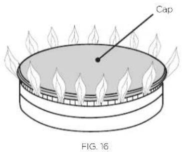
Your side burner is equipped with burners typical of those used in restaurants. These burners are designed for maximum cleanability and controlability. The burner should never be operated if the cap is not in place (Fig. 16).
Grilling
Grill
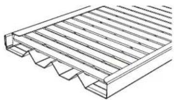
Each grill section consists of a large stainless steel burner, stainless steel heat baffles, a series of ceramic rods encased in a stainless steel radiant, and a stainless steel heat retaining grate. Each burner is rated at 25,000 Btu/hr or 26,5MJ/h. Below the burners there is a stainless steel heat baffle which reflects usable heat upward into the cooking area and reduces temperatures of the drip pan below. Above the burners are stainless steel radiants which encase the ceramic rods and protect the grill burner ports from blockage (Fig. 17).
natural_image
Technical line drawing of a metal grate structure with ribbed and stepped components (no text or symbols)FIG.17
The grill is supplied with radiant ceramic rods. Because of the porosity of ceramic rods, performance is superior in the rods' ability to capture heat as it rises from the grill burners. They also possess the thermal mass needed for even cooking performance. Flare ups are controlled because the radiant ceramic rods keeps grease from getting to the flames and igniting. The intense heat produced by this system produces true grilled flavor as fats and juices are brought to the surface of the food and caramelized. Discoloration of the grates is normal after use.
Direct/indirect cooking notes
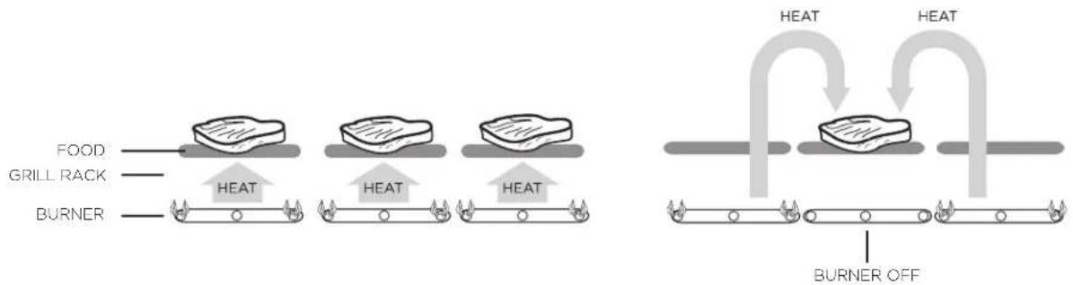
Direct cooking involves placing food on grates over lighted burners. Use this method for foods that take less than 20 minutes to cook or to sear larger items at the start of the cooking process that will then be indirectly cooked to finish. Place items on the preheated surface and leave until they no longer stick. Turning too soon and too often is one of the most common grilling mistakes. Never spray water on the grill or into grease. The patented Grease Management System™ reduces flare-ups by channeling grease away from the flame. Use a meat thermometer to achieve desired doneness and remove items one degree below how you would like to enjoy them, as the resting period before carving or consuming will raise the temperature.
Indirect cooking method is a popular alternative to direct heat grilling. Indirect cooking uses heat from adjacent burners to cook food and, in many cases, reduces the possibility of overcooked or overly browned food. Foods most appropriate for indirect grilling included breads, thicker pieces of chicken or steaks. Indirect cooking involves placing the food on grates where the burners below are not lit and then closing the grill top to create an oven effect. All the items you usually oven-roast can be grilled to perfection using indirect heating. Preheat the burners surrounding the food to be cooked. Use your basting pan to hold food and add water or chicken broth to the pan to prevent the natural juices from burning or evaporating.
Direct Heat Grilling Indirect Heat Grilling
IMPORTANT!
- Season your grates before first use and then periodically to protect the grate surface from corrosion, and to stop food sticking. See 'Care and Maintenance'. To season the grates, pour a tablespoon of vegetable oil on a soft cloth and rub on both sides of the grates. Only a light coating is needed and some smoke may be visible during the preheating.
- Grilling requires high heat for searing and proper browning. Most foods are cooked at the “MEDIUM” to “LOW” heat setting for the entire cooking time. However, when grilling large pieces of meat or poultry, it may be necessary to turn the heat to a lower setting after the initial browning. This cooks the food through without burning the outside. Foods cooked for a long time or basted with a sugary marinade may need a lower heat setting near the end of the cooking time.
Grilling
① Ensure that the drip pan and grease tray are in place.
② Light the grill burners following the lighting instructions.
③ Once you have verified the burners are lit, put the hood down to preheat for five to 10 minutes.
④ Place the food on the grill and cook to the desired doneness. Adjust heat setting, if necessary. The control knob may be set to any position between “SEAR” and “LOW”.
⑤ When you have finished using the grill, turn the control knobs to "OFF" and shut off the main gas supply.
⑥ Allow the grill to cool and clean the grates, drip pan and grease tray after each use.
Note: if using LP gas, your preheat time may be shorter than recommended. To prevent overcooking or burning, you may want to lower the heat settings.
Using the temperature gauge
When preheating the grill, use the temperature gauge in the hood to check if the grill has reached the desired heat setting.
Note: the temperature gauge only indicates air temperature inside the grill. For food safety and optimal cooking performance, use a meat probe to check the temperature of meat while cooking and to ensure desired internal temperatures are reached.
Dual-sided grates
Whether you or your guests crave seafood, steak or veggies, the double-sided grates provide varying surfaces for varying textures. The “W”-shaped side creates nice sear lines for steaks, chicken and chops and routes oil and grease away from the food. The opposite “radius” side offers more surface area for support and handling of delicate items like scallops (see below for a sample list of which foods to cook on which side of the grate).
| "W" SHAPED GRATE RADIUS GRATE | |
| Chicken (bone-in and boneless cuts) | Delicate fish fillets |
| Steaks | Lobster meat |
| Chops | Shrimp |
| Burgers | Scallops |
| Ribs | Clams |
| Kabobs | Mussels |
| Steak cuts of fish like tuna and swordfish | Suckling pig |
| Whole fish | Turkey legs |
| Game | Indirect cooking and smoking |
| Oysters | Potatoes |
| Large slices of whole vegetables | Smaller vegetables or slices |
| Fruit | Roasted peppers |
| Bread | Roasted whole garlic |
| Sausages | Pizza dough and flat breads |
| Hot dogs | Crab cakes |
Grilling hints
The doneness of meat, whether rare, medium or well done, can depend on the thickness of the cut. The cooking time of meat is dependent on the kind of meat, size, shape and cut along with the temperature of the meat when cooking begins. Expert chefs say it is impossible to have a rare doneness with a thin cut of meat. When defrosting meats, it is recommended to defrost overnight in a refrigerator as opposed to a microwave. This will ensure meat retains it juices. Use a spatula instead of tongs or a fork to turn the meat, as a spatula will not puncture the meat and let the juices run out. To get the juiciest meats, add seasoning or salt after the cooking is finished and turn the meat only once (juices are lost when the meat is turned several times). Turn the meat just after the juices begin to bubble to the surface. Trim any excess fat from the meat before cooking. To prevent steaks or chops from curling during cooking, slit the fat around the edges at two-inch intervals.
The cuts, temperatures, weights and grilling times in the following charts are meant to serve as a guideline. Environmental factors such as wind, outside temperature and altitude can affect cooking times, so should be taken into consideration. The USDA's definition of medium doneness is used for the cooking times of beef and lamb, unless otherwise stated. Before carving, let roasts and other large cuts of meat (including thick steaks) rest for 5 to 10 minutes after cooking. The internal temperature will increase slightly during this time.
For indirect cooking, we suggest placing the meat in the secondary cooking area in the lower or upper position depending on size and desired temperature.
Cooking Chart - Main Grill
BEEF:
| FOOD TYPE THICKNESS WEIGHT METHOD | TEMP CONTROL DIAL | APPROX TIME (HRS/MINS) | ||||
| Steak | New York Strip | 1" Thick Direct High Heat 4-8 min | ||||
| Porterhouse 1" | Thick Direct High Heat 6-8 min | |||||
| Rib-Eye 1" Thick Direct High Heat 6-8 min | ||||||
| T-Bone 1" Thick Direct High Heat 6-8 min | ||||||
| Ground Beef Patty 5 oz Direct Low-Medium Heat 10-14 min | ||||||
| Fajitas | 3/4" Thick | 3 lb | Direct | Low-Medium Heat | 20 min | |
| Finger Rib | 2 lb | Direct/Indirect | Low-Medium Heat | 1-2 hours | ||
| Brisket | 3-5 lb | Direct/Indirect | Low Heat | 2-3 hours | ||
LAMB:
| FOOD TYPE THICKNESS WEIGHT METHOD | TEMP CONTROL DIAL | APPROX TIME (HRS/MINS) | |||
| Chop | 1" Thick | Direct | High Heat | 4-8 min | |
| Leg of Lamb Roast | 3-7 lb | Direct/Indirect | Low | 2-3 hours | |
| Rack of Lamb | 1-2 lb | Direct/Indirect | Low-Medium Heat | 15-20 min | |
PORK:
| FOOD TYPE THICKNESS WEIGHT METHOD | TEMP CONTROL DIAL | APPROX TIME (HRS/MINS) | |||
| Hot Dog | 2-4 oz | Direct/Indirect | Low Heat | 5 min | |
| Bratwurst | 4 oz Link | Direct/Indirect | Low Heat | 10-15 min | |
| Ribs: Baby Back | 3-5 lb | Direct/Indirect | Low Heat | 3-4 hours | |
| Spare Ribs | 3-5 lb | Direct/Indirect | Low Heat | 4-6 hours | |
| Boston Butt/Shoulder | 3-7 lb | Direct/Indirect | Low Heat | 4-6 hours | |
Grilling
Cooking Chart - Main Grill
POULTRY:
| FOOD TYPE THICKNESS WEIGHT METHOD | TEMP CONTROL DIAL | APPROX TIME (HRS/MINS) | ||||
| Chicken Breast | Boneless | 6 -7 oz | Direct/Indirect | Low-Medium Heat | 10-12 min | |
| Chicken Thigh | Boneless | 3-5 oz | Direct/Indirect | Low-Medium Heat | 10-12 min | |
| Chicken Whole | 3-5 lb | Indirect/Rotisserie | Medium Heat | 1-2 hours | ||
| Duck Whole | 3-5 lb | Indirect/Rotisserie | Medium Heat | 1-2 hours | ||
| Turkey Whole | 10-12 lb | Indirect/Rotisserie | Medium Heat | 2-3 hours | ||
SEAFOOD:
| FOOD TYPE | THICKNESS WEIGHT METHOD | TEMP CONTROL DIAL | APPROX TIME (HRS/MINS) | |||
| Fish Fillet/Steak: | Halibut | 12 - 1" Thick | Direct | Medium Heat | 6-10 min | |
| Snapper | 12 - 1" Thick | Direct | Medium Heat | 6-10 min | ||
| Salmon | 12 - 1" Thick | Direct | Medium Heat | 6-10 min | ||
| Sea Bass | 12 - 1" Thick | Direct | Medium Heat | 6-10 min | ||
| Swordfish | 12 - 1" Thick | Direct | Medium Heat | 6-10 min | ||
| Tuna | 12 - 1" Thick | Direct | Medium Heat | 6-10 min | ||
| Trout | 12 - 1" Thick | Direct | Medium Heat | 6-10 min | ||
| Shrimp | 2-4 oz | Direct | Medium Heat | 4-5 min | ||
| Fish Whole | 3-5 lb | Indirect | Low-Medium Heat | 20-30 min | ||
VEGETABLES:
| FOOD TYPE | THICKNESS | WEIGHT | METHOD | TEMP CONTROL DIAL | APPROX TIME (HRS/MINS) |
| Aubergine | 1" Thick Slices | Direct | Low Heat | 4-6 min | |
| Asparagus | 12" Stem Diameter | Direct | Low Heat | 4-6 min | |
| Corn on the Cob | Whole | Direct/Indirect | Low Heat | 20-25 min | |
| Mushroom - Portobello | Whole | Direct | Low Heat | 8-10 min | |
| Onion | 12" Thick Slices | Direct | Low Heat | 10-12 min | |
| Peppers | Halved | Direct | Low Heat | 8-10 min | |
| Potato | 12" Thick Slices | Direct | Low Heat | 10-15 min | |
| Tomato | Halved | Direct | Low Heat | 4-6 min | |
| Zucchini | 1" Thick Slices | Direct | Low Heat | 4-6 min | |
| Sweet Potato | 1" Thick Slices | Direct | Low Heat | 10-12 min |
FRUIT:
| FOOD TYPE | THICKNESS | WEIGHT | METHOD | TEMP CONTROL DIAL | APPROX TIME (HRS/MINS) |
| Bananas | Halved | Direct | Low Heat | 5-6 min | |
| Peaches | Halved | Direct | Low Heat | 6-8 min | |
| Apricots | Halved | Direct | Low Heat | 6-8 min | |
| Nectarines | Halved | Direct | Low Heat | 6-8 min | |
| Pineapple | 12 " Thick Slices | Direct | Low Heat | 5-6 min |
* Slow cooking of some meat cuts may require surfaces to be seared over direct high heat prior to indirect cooking.
Grilling
Cooking Chart - Smoking
BEEF:
| FOOD TYPE THICKNESS WEIGHT METHOD | TEMP CONTROL DIAL | APPROX TIME (HRS/MINS) | ||
| Brisket 4-6 lb Indirect Low Heat 6-8 hours | ||||
| LAMB: | ||||
| FOOD TYPE THICKNESS WEIGHT METHOD | TEMP CONTROL DIAL | APPROX TIME (HRS/MINS) | ||
| Leg of Lamb Roast 3-7 lb Direct/Indirect Low Heat 2-3 hours |
PORK:
| FOOD TYPE THICKNESS WEIGHT METHOD | TEMP CONTROL DIAL | APPROX TIME (HRS/MINS) | ||
| Ribs: Baby Back 3-5 lb Indirect Low Heat 4-5 hours | ||||
| Spare Ribs 3-5 lb Indirect Low Heat 5-6 hours | ||||
| Boston Butt/Shoulder 3-7 lb Indirect Low Heat 6-8 hours |
POULTRY:
| FOOD TYPE THICKNESS WEIGHT METHOD | TEMP CONTROL DIAL | APPROX TIME (HRS/MINS) | |||
| Chicken Whole | 3-5 lb Indirect Low Heat 2-4 hours | ||||
| Duck Whole | 3-5 lb Indirect Low Heat 2-4 hours | ||||
| Turkey Whole | 10-12 lb | Indirect | Low Heat | 8-10 hours | |
SEAFOOD:
| FOOD TYPE THICKNESS WEIGHT METHOD | TEMP CONTROL DIAL | APPROX TIME (HRS/MINS) | ||||
| Fish Fillet/Steak: | Salmon | 12 - 1" Thick | Indirect | Low Heat | 1 hour | |
| Swordfish | 12 - 1" Thick | Indirect | Low Heat | 1 hour | ||
| Tuna | 12 - 1" Thick | Indirect | Low Heat | 1 hour | ||
| Trout | 12 - 1" Thick | Indirect | Low Heat | 1 hour | ||
| Mackerel | 12 - 1" Thick | Indirect | Low Heat | 1 hour | ||
| Shrimp | 2-4 oz | Indirect | Low Heat | 1 hour | ||
| Fish Whole | 3-5 lb Indirect Low Heat 3-4 hours | |||||
VEGETABLES:
| FOOD TYPE | THICKNESS | WEIGHT | METHOD | TEMP CONTROL DIAL | APPROX TIME (HRS/MINS) |
| Aubergine | 1" Thick Slices | Indirect | Low Heat | 1 hour | |
| Corn on the Cob | Whole | Indirect | Low Heat | 112 hours | |
| Mushroom - Portobello | Whole | Indirect | Low Heat | 112 hours | |
| Onion | Whole/halved | Indirect | Low Heat | 2 hours | |
| Peppers | Whole/halved | Indirect | Low Heat | 112 hours | |
| Potato | Whole/halved | Indirect | Low Heat | 2 hours | |
| Tomato | Whole/halved | Indirect | Low Heat | 45 minutes | |
| Zucchini | Halved lengthwise | Indirect | Low Heat | 1 hour | |
| Sweet Potato | Whole/halved | Indirect | Low Heat | 2 hours |
Grilling
Meat Temperatures
The “Remove” temperature on the left is the target temperature to remove from heat source. The “Ideal” temperature on the right is the ideal internal temperature after resting. These temperatures are all Fahrenheit. Note, these are not USDA Recommendations. The USDA temperatures are conservatively 10^-15^ higher because of food safety however most professional chefs will not cook a medium-rare steak to 150^ .
FOOD TYPE RARE MEDIUM-RARE MEDIUM MEDIUM-WELL
| REMOVE IDEAL REMOVE | IDEAL | REMOVE IDEAL REMOVE | IDEAL | |||||
| Beef Steaks | 125^ 130^ | 130^ 135^ | 140^ 145^ | 155^ 160^ | ||||
| Beef Roasts | 120^ 125^ | 125^ 130^ | 135^ 145^ | 150^ 160^ | ||||
| Lamb Chops | 125^ 130^ | 130^ 135^ | 135^ 145^ | 155^ 160^ | ||||
| Lamb Roast | 120^ 130^ | 125^ 130^ | 135^ 145^ | 150^ 160^ | ||||
| Pork Chops | 125^ 130^ 135^ | 140^ 145^ | 150^ | |||||
| Pork Roasts | 125^ 130^ | 135^ 140^ | 145^ 150^ | |||||
| Veal Chops | 130^ 135^ | 140^ 145^ | 155^ 160^ | |||||
| Veal Roasts | 125^ 130^ | 135^ 145^ | 150^ 160^ | |||||
| FOOD TYPE | RESTING TIME | REMOVE | IDEAL INTERNAL TEMPERATURE |
| Whole Chicken - Roasted | 5 minutes | 160^ - 165^ | 165^ - 170^ |
| Whole Turkey - Roasted* | 20-60 minutes | 150^ - 170^ | 165^ - 170^ |
* A large Turkey can take 60 minutes of resting with a temperature shift of 20^ or more
The smoker system on each grill consists of a stainless steel slide out tray which is positioned above a 3,500 Btu/hr or 3.7 MJ/h burner. The burner is controlled by a precision brass valve which is capable of being turned down to very low heat levels. The system may be used alone for low temperature roasting and smoking or in conjunction with any combination of other burners. When using the smoker system in conjunction with the optional infrared rotisserie burner, you'll find it helpful to use the low setting of the smoker burner to minimize the heat rising up to the rotisserie basting pan. Staggering the meat away from the smoker burner also helps.
To minimize burn potential do not completely remove the smoker tray when hot.
To light the smoker burner
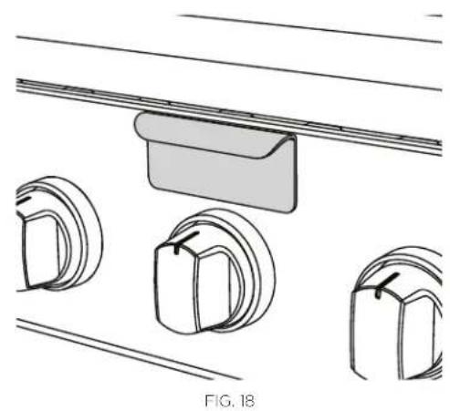
Open the lid and remove the smoker tray. Locate the burner visually by looking through the cut-out in the valve panel. Push in the burner knob and turn to the "HI" position until the burner is lit. If the burner doesn't ignite, wait five minutes for any accumulated gas to dissipate, then try again. If the burner will not light after several attempts, wait five minutes, then match light using a paper book match through the cut-out in the valve panel. Once lit, fill the smoker tray and replace.
Wood chips
There are many wood chips available for purchase and selection is based on personal taste. The most common wood chips used are mesquite or hickory. Mesquite has a sweeter taste and is commonly used with poultry and seafood. Hickory is best suited for red meats. Use of oak, cherry, maple, aspen or apple is also common while aromatic herbs like sage, bay leaves, thyme or basil may also be used. Soaking the chips in water before using them will help ensure the wood chips smoke and do not flame up. To start, you may want to use the "HI" position to start the chips smoking, then reduce the heat to a lower level to prevent them from drying out and flaming. If the wood chips do flame up, add a small amount of water to extinguish the flame. This should be done carefully through the top in the grill area, or by pulling the tray out slightly. Use caution when adding water to a hot tray to avoid steam burns, and never completely remove a hot tray. When smoking, the lid should remain closed as much as possible to maximize the effect. During extended roasting periods it is normal to add fresh wood chips to the tray several times.
Your smoker tray comes with a removable smoker lid. For best results we recommend using the smoker lid.
natural_image
Technical line drawing of a mechanical assembly with three circular components and a bracket (no text or symbols)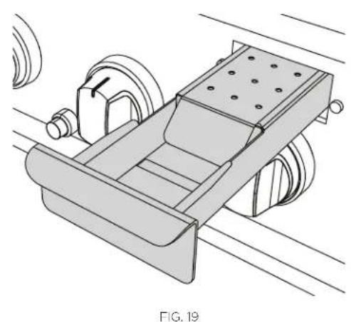
natural_image
Technical line drawing of a mechanical device with rollers and a conveyor belt (no text or symbols)The grill rotisserie system is designed to cook items from the back using infrared heat. The location of the burner allows the placement of the rotisserie basting pan (included) beneath the food to collect juices and drippings for basting and gravy. To flavor the contents of the basting pan, you can add herbs, onion, garlic, or spices. Hams are especially good with the addition of pineapple slices and brown sugar to the basting pan. The rotisserie burner is an infrared type which provides intense searing radiant heat. Preferred by chefs over other methods, this intense heat is magnificent for searing in the natural juices and nutrients found in quality cuts of meat.
Once lit, the rotisserie burner will reach cooking temperatures in about one minute. The orange/red glow will even out in about five minutes. The rotisserie motor is equipped with metal gears and is capable of turning up to a 50 lb. cut of meat or poultry. The rotisserie motor on the grills is secured down to a cast rotisserie block with two black screw-down knobs. The rotisserie block is in turn bolted to the right side panel. The rod for the rotisserie is assembled into the motor assembly by placing the pointed end into the motor, and resting the handle end on the support at the left side of the grill. With the rod pushed as far as possible into the motor, the round end of the rod should rest on the rollers.
The motor is equipped with a halogen bulb to provide light when other sources of light are not sufficient. Use only a 50W (or its equivalent) Max. Halogen Narrow Flood replacement bulb.
IMPORTANT!
Halogen lamps are constructed of a glass bulb with a pressurized internal filament tube that operates at high temperatures and could unexpectedly shatter. Should the outer bulb break, particles of extremely hot glass could be discharged into the fixture enclosure and/or surrounding environment, thereby creating a risk of personal injury or fire. When replacing the bulb, let the bulb cool, and assure that power to the light has been turned off. Never allow the hot bulb to come into contact with water. DO NOT TOUCH the light bulb when in use. It may be hot enough to cause injury.
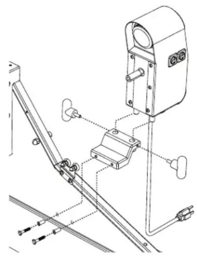
natural_image
Technical line drawing of a mechanical assembly with no visible text or symbolsFIG. 20
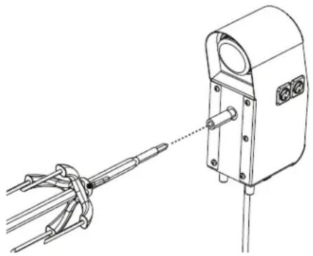
natural_image
Technical line drawing of a mechanical device with a connecting rod and lever assembly (no text or symbols)FIG. 21
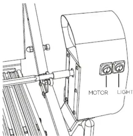
FIG. 22
IMPORTANT!
Do not use the grill burners when the rotisserie burner is on. It will burn your meat and make it very dry. Use only one section at a time, grill or rotisserie.
Preparation
Recommended: dental floss or butcher string, scissors, broiler pan (bottom only), pliers, meat probe, foil, and hot pads.
Working area
Allow enough space to accommodate food and rotisserie rod assembly in a clean environment.
Meat preparation
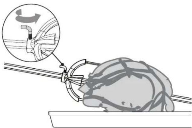
Tie meat with butcher string or dental floss in three areas. Purchase a roast that is equally balanced from top to bottom in size to ensure meat will cook evenly while on the rotisserie. For poultry, tie wings and legs to the body using dental floss or butcher string to prevent flopping around while turning.
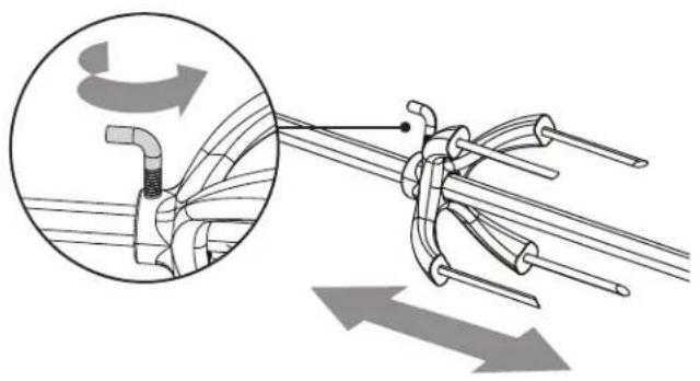
natural_image
Diagram of mechanical linkage or cable assembly with directional arrows, no text or symbols present① Determine the center placement for the food, put first prong on the rod, turn "L"-shaped screw to tighten.
natural_image
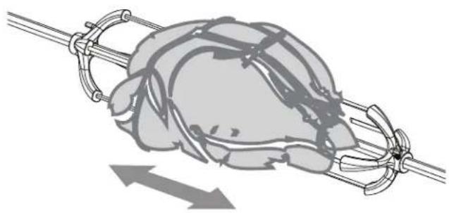
Illustration of a hand gripping a large object with rope and metal chains, showing motion direction (no text or symbols)② Center tied meat/poultry on the rod, place second prong, turn "L"-shaped screw to tighten.
natural_image
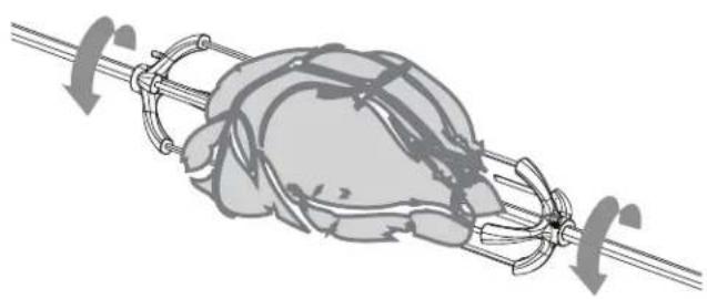
Illustration of a hand gripping a rope with chains and ropes, no text or symbols present③ Pick up the rod, rotate it to check for balance. If unbalanced, adjust prongs and food. Take pliers and tighten the "L"-shaped screws on both prongs.
natural_image
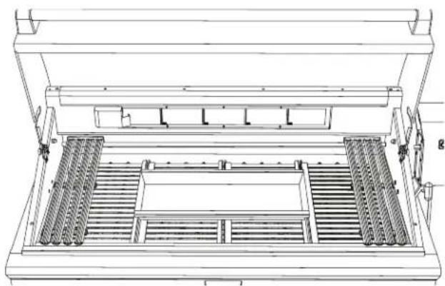
Technical line drawing of a mechanical device with internal compartments and structural supports (no text or symbols)④ Remove grates and top rack on the grill. Place bottom portion of basting pan on ceramic rods so meat drippings can be caught in pan.
To light the rotisserie burner before cooking
The location of the rotisserie burner makes it more susceptible to strong wind conditions, more so than the protected grill burners. For this reason you should avoid operating the rotisserie during windy conditions. As an added safety feature we've equipped the burner with an automatic safety valve which will not allow gas to flow to the rotisserie burner unless the following conditions are present with the knob on:
① The safety valve button is pressed, and held down.
② The safety valve thermocouple has been sufficiently heated to keep safety valve open.
Open the lid. Push in and hold the burner knob. You'll hear a snapping sound. Turn the burner knob to "HI". Engage the safety valve button and continue to hold until the burner is lit. Once lit, turn burner knob to desired setting. If the burner does not light within four to five seconds, release the safety valve button and turn the burner knob to "OFF" and wait five minutes before trying again.
• If relighting a hot burner, wait five minutes.
- Never leave the control knob on if rotisserie is not in use.
- Never light the grill burners under the rotisserie while the rear rotisserie burner is lit.
Manual lighting
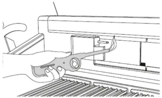
To manually light the rotisserie, place a butane lighter near the tip of the thermocouple as shown in Fig. 23. Turn the burner knob to "HI". Hold the safety valve button in for about four to five seconds or until the burner remains lit. Once lit, turn burner knob to desired setting. If the burner does not light within four or five seconds, release the safety valve button and turn the burner knob to "OFF" and wait five minutes before trying again.
IMPORTANT!
Keep hands and face away from front of burner! Stand to the side when lighting. Once lit move hand away quickly.
natural_image
Line drawing of a hand using a tool to adjust or install a mechanical component (no text or symbols present)FIG. 23
IMPORTANT!
Electrical Grounding Instructions: this appliance (rotisserie motor) is equipped with a three-prong (grounding) plug for your protection against shock hazard and should be plugged directly into a properly grounded three-prong receptacle or a three-prong grounded extension cord rated for the power of the rotisserie motor and approved for outdoor use with a W-A marking. Do not cut or remove the grounding prong from this plug. Use only a ground fault interrupter (GFI) protected circuit.
The rotisserie motor must be electrically grounded in accordance with local codes or, in the absence of local codes, with the National Electrical Code, ANSI/NFPA 70. Keep the rotisserie motor electric cord away from the heated surfaces of the grill. When not in use, remove and store the motor in a dry location. To protect against electric shock, do not immerse the cord or plug in water or other liquid. Unplug rotisserie unit from the outlet when not in use and before cleaning. Allow the rotisserie to cool before putting on or taking off parts.
Cooking on the rotisserie
natural_image
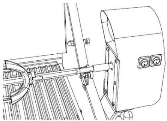
Technical line drawing of a mechanical assembly with no visible text or symbols① Place prepared rod into motor, lay across and into the rollers on other side.
natural_image
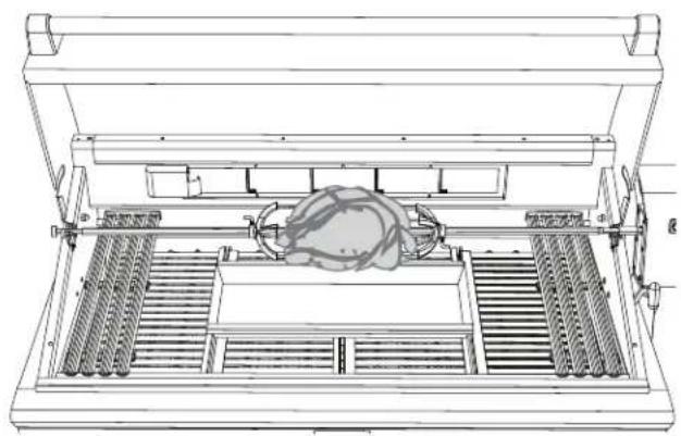
Technical line drawing of a mechanical device with internal components and no visible text or symbols② Once placement has been verified, ignite burner and start rotisserie motor. Turn the burner knob to the desired setting.
natural_image
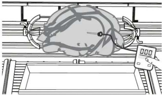
Illustration of a robotic arm with a globe and sensor device (no text or symbols)③ To check temperature of the meat, turn off motor and turn temperature to low while using a meat probe.
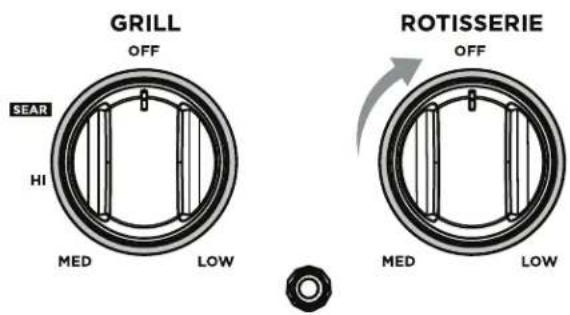
④ Once finished, turn the motor and rotisserie knob to "OFF". If you have finished using the appliance altogether, turn the main gas supply off too.
natural_image
Diagram of a mechanical assembly with a magnified inset showing a component being inserted into a housing (no text or symbols present)⑤ Remove the rod and place meat or poultry on pan then remove prongs. Take care as the rod will be hot.
IMPORTANT!
The prongs are very sharp. Keep hands away from tips when removing the food.
Note: cover with foil for a 15 to 20 minute waiting time. Meat will carve better and juices will go back into the meat.
Battery replacement
IMPORTANT!
Battery condition should be checked at least once a year.
① Remove drip pan.
② Open cart door (on cart model only).
③ Pull battery downwards (this may require use of pliers).
④ Re-install upward and push to snap (polarity shown in Fig. 24).
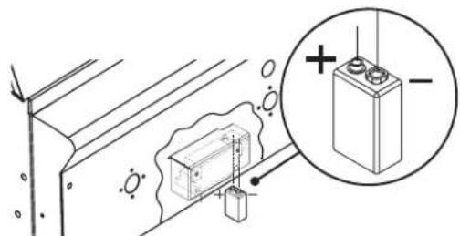
FIG. 24
Regulator and hose replacement
The pressure regulator and hose assembly supplied with the unit must be used. If replacements are needed, contact Customer Care at www.dcsappliances.com. Do not use the grill if the odor of gas is present. If the unit is LP, screw the regulator into the tank and leak check the hose and regulator connections with a soap and water solution before operating the grill. Turn all knobs to "OFF" then turn on the gas supply. If LP, check that there is gas in the tank.
IMPORTANT!
• Always keep your face and body as far away from the grill as possible when lighting.
• DO NOT leave the grill unattended while cooking.
- Keep a spray bottle of soapy water near the gas supply valve and check connections before each use.
- Do not attempt to light the grill if the odor of gas is present.
- Wait five minutes before relighting a hot grill.
Grill grates
Method 1
Turn on "HI" for 15-20 minutes to burn any remaining food particles. After turning the grill "OFF", use a bristle barbeque brush to remove any remaining food particles or ash.
Method 2
The easiest way to clean the grill is immediately after cooking is completed and after turning off the flame. Wear a barbeque mitt to protect your hand from the heat and steam. Dip a soft brass bristle barbeque brush in a mixture of 2 cups of tap water and 1/2 cup of vinegar and scrub the hot grill. Dip the brush frequently in the bowl of water and vinegar. Steam, created as water contacts the hot grill, assists the cleaning process by softening any food particles. The food particles will fall onto the ceramic rods and burn or fall into the drip pan. If the grill is allowed to cool before cleaning, cleaning will be more difficult.
Method 3
Take about 1 foot of aluminum foil, crumpled up in a ball and rub it over cooled grates to release food particles.
Note: grill grates must be re-seasoned after cleaning to prevent rust stains.
Drip pan and grease tray
The full width drip pan with grease tray will collect grease from the grill section and boil overs and spills from the side burners. Allow the pan and its contents to cool before attempting to clean. Clean grease from the pan often to avoid the possibility of a grease fire.
Ceramic rods
It is not necessary to remove the ceramic rods for cleaning. They burn themselves clean during the next cooking operation. Periodically the trays holding the ceramic rods need to be turned over, and shaken free of debris for a thorough cleaning. How often you use the grill and the amount and type of food cooked will determine when it is necessary to clean the trays. If grease can be seen on the top of the tubes or if you get a lot of flare-up during cooking, the tubes need to be turned over and heated on "HI" for 30 minutes; longer for heavy soil.
Stainless steel
The grill is made from non-rusting and non-magnetic stainless steel. After initial usage, areas of the grill may discolor from the intense heat given off by the burners, this is normal. There are many different stainless steel cleaners available. Always use the mildest cleaning procedure first, scrubbing in the direction of the grain. To touch up noticeable scratches in the stainless steel, sand very lightly with wet 100 grit emery paper in the direction of the grain. Specks of grease can gather on the surfaces of the stainless steel and bake on to the surface and give the appearance of rust. For removal use an abrasive pad (Scotch Brite is good) in conjunction with a stainless steel cleaner. Always rub in the direction of the grain.
Note: stainless steel tends to corrode in presence of chlorides and sulfides especially in coastal areas. To ensure corrosion prevention, wash all stainless steel surfaces every three to four weeks with fresh water and stainless cleaner. Keep grill covered when not in use.
Electrodes
Wipe with a water dampened cotton swab. Be careful not to damage the electrode (see Fig. 25).
To remove the U-Burners for Cleaning
Ensure gas supply has been turned off. Remove the grill grates, then lift out the grill radiant tray. Grip the U-burner as shown in the photo (Fig. 27) and press downwards with your thumbs on the bracket in the back while lifting up on the U-Burner. In some cases it may be necessary to use a screw driver to pry open the slot to release the U-burner (Fig. 26). Pull it up and slightly to the rear of the unit so the burner air shutter head comes off the brass orifice at the front, angle the burner sideways, and remove. After cleaning, when re-installing the U-Burner ensure the U-Burner is completely level and locked in place. This is needed to ensure your grill provides even cooking performance.
Grill burner cleaning
Clean the exterior of the burner with a stainless steel wire brush. Clear stubborn scale with a metal scraper. Clear any clogged ports with a straightened paper clip. Never use a wooden toothpick as it may break off and clog the port. Shake out any debris through the air shutter. Use a flashlight to inspect the burner inlet to ensure it is not blocked. If obstructions can be seen, use a metal wire coat hanger that has been straightened (See Fig. 28).
Orifice cleaning
With the burner removed, remove the orifice and shine a flashlight through the opening to ensure there is no blockage. Use a needle to clear any debris. Be extremely careful not to enlarge the hole or break off the needle.
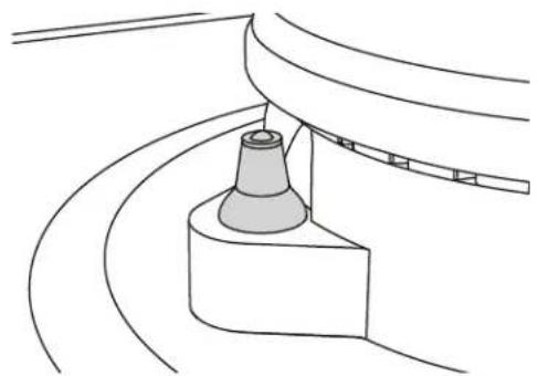
natural_image
Pure technical line drawing of a mechanical component with curved surfaces and a central cylindrical part (no text or symbols)Fig. 25
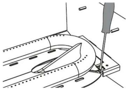
natural_image
Technical line drawing of a mechanical assembly with a tool inserted, showing no text or symbolsFig. 26
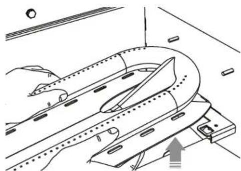
natural_image
Technical line drawing of a mechanical component with no visible text or symbolsFig. 27
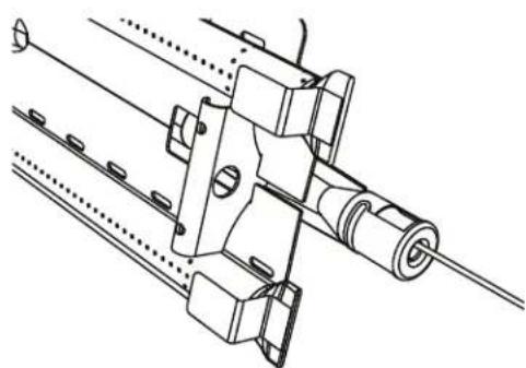
natural_image
Technical line drawing of a mechanical assembly with shafts and mounting brackets (no text or symbols)Fig. 28
Burner alignment
IMPORTANT!
Center the burner onto the orifice properly before lighting the grill to prevent fire hazard or explosion.
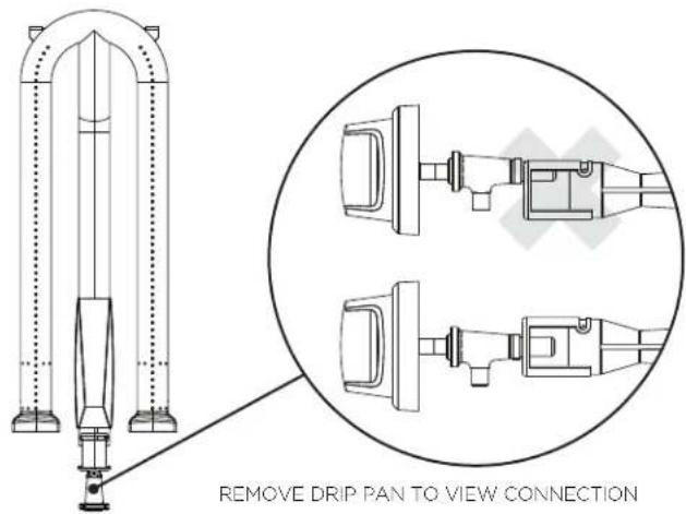
Fig. 29 Fig. 30
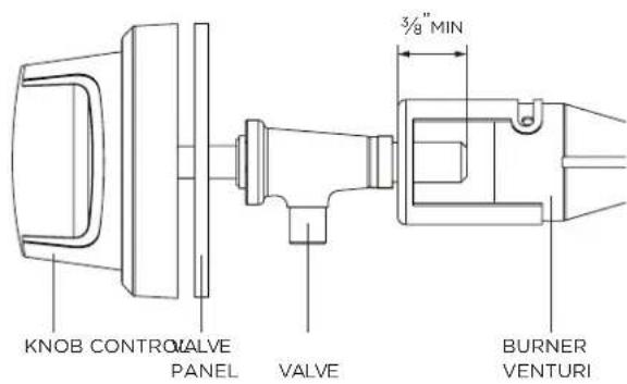
Be careful not to misalign the air shutters' original position (unless readjusting). Lower the rear of the burner into the cutouts on the support channel at the rear of the burner box. Make sure it is level and does not rock. Light all of the burners and check that the flame is blue, stable and even. If adjustments are necessary, refer to page 18. Complete these adjustments prior to cooking.
Side burners (BH1-48RS model)
For proper lighting and performance keep the burners clean. It is necessary to clean the burners if they do not light even though the electrode clicks, if there has been a severe boil over, or when the flame does not burn blue. Be certain all control knobs are in the off position before attempting to clean the burners. The burners have been designed for ease in cleaning. When the grates and burners are cool, remove the grate. The burner cap and the brass port ring can easily be lifted off. Wash these parts in hot soapy water, rinse and dry thoroughly. The burner caps are porcelain enamel. A bristle brush can be used to clean out the toothed burner ports, if necessary. After cleaning, it is important to make sure the location pins on the bottom side of the port ring are properly aligned with the corresponding holes in the base. Incorrect alignment will produce a potentially dangerous flame and poor burner performance (see Fig. 31).
Smoker burner
The smoker burner can be removed and cleaned by unplugging the electrode wire and lifting out the burner. Cleaning is similar to the grill burner. Replace the burner by sliding the air shutter over the brass orifice, centering it in the hole.
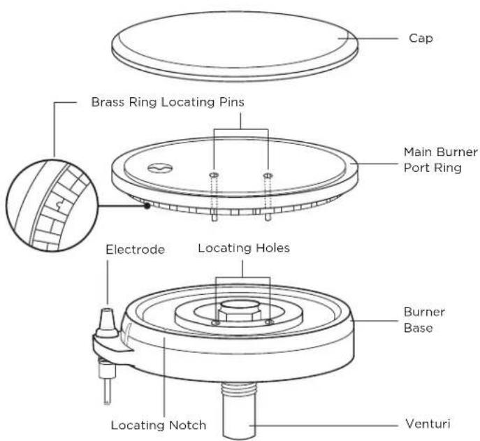
FIG. 31
Before calling for service
If the grill does not function properly, use the following checklist before contacting your dealer for service. You may save the cost of a service call. Troubleshooting is for general purposes only. If the problem persists and you feel you require service, contact your dealer or the nearest authorized agency to perform service. Only authorized agencies can perform warranty service. Contact DCS at www.dcsappliances.com
| PROBLEM WHAT TO DO | |
| Grill won’t light when the burner knob is pushed. | Check the gas supply is on.Ensure the grill is cool. Remove the grill top grates and the ceramic radiant trays, watch the electrode tip. You should see a spark jump from the tip of the ignition when the burner knob is pushed in.If there is no spark when burner knob is pushed in, check the battery condition. Battery condition should be checked at least once a year.Attempt to match light the burner (see page 21, 22 & 32). Check to see that other burners on the unit operate. Clean electrode tip of any debris. |
| Burner flame is yellow or orange, in conjunction with the odor of gas. | Check the burner inlet for obstructions such as spider webs.Check the air shutter for proper adjustment.Grill may be in a dusty area. Move to less dusty area if possible. |
| Low heat with knob in “HI/SEAR” position. | If only one of the burners appears low, clean the orifice and burner, clearing ports of any obstruction (see page 35).Grill may be in a dusty area. Move to less dusty area if possible.Check for proper gas supply and pressure.Pre-heat grill for a full 15 minutes.If using LP gas, check for empty tank. |
| Rotisserie won’t light. | Check the gas supply is on.Check there is a spark at the electrode.Check the rotisserie burner lights when attempting to light with a butane lighter. |
| Rotisserie lights, but will not hold flame once button is released. | Continue holding safety valve button in depressed position until burner remains lit when released. |
How to obtain service
For warranty service, please contact your local service provider or through our website www.dcsappliances.com. Please have the following information:
- Model number (can be found on the inside, right side panel behind the drip pan handle. See page 20).
- Serial number (can be found on the inside, right side panel behind the drip pan handle. See page 20).
- Code (can be found on the inside, right side panel behind the drip pan handle. See page 20).
- Date of installation.
• A brief description of the problem.
Your satisfaction is of the utmost importance to us. If a problem cannot be resolved to your satisfaction, please write or email us at:
Write
Fisher & Paykel Appliances Inc.
Attention: DCS Customer Care 695 Town Center Drive, Suite 180
Costa Mesa. CA 92626-1902 USA
customer.care@fisherpaykel.com
Complete and keep for safe reference:
| Model | |
| Serial No. | |
| Purchase Date | |
| Purchaser | |
| Dealer | |
| Suburb | |
| Town | |
| Country |
▲ AVERTISSEMENT!
NEVER store a spare LP cylinder under or near this unit.
NEVER fill the tank beyond 3/4 full.
A fire causing death or serious injury may occur.
P/N 137147 Rev. 8
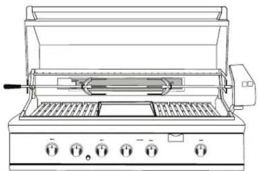
natural_image
Line drawing of a portable electric stove with open lid and control knobs (no text or symbols)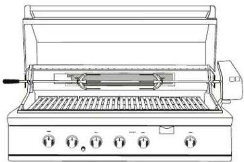
natural_image
Line drawing of a portable electric grill with control knobs and grilles (no text or symbols)BH1-48RBH1-48RGI
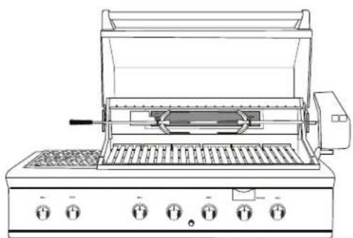
natural_image
Line drawing of a portable electric grill with control knobs and grilles (no text or symbols)BH1-48RS
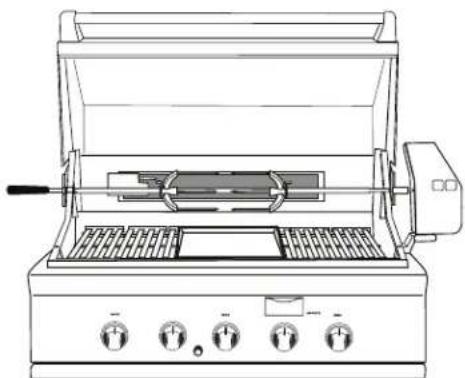
natural_image
Line drawing of a portable electric stove with control knobs and grilles (no text or symbols)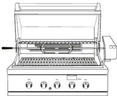
natural_image
Line drawing of a portable electric grill with control knobs and grating (no text or symbols)BH1-36RBH1-36RGI
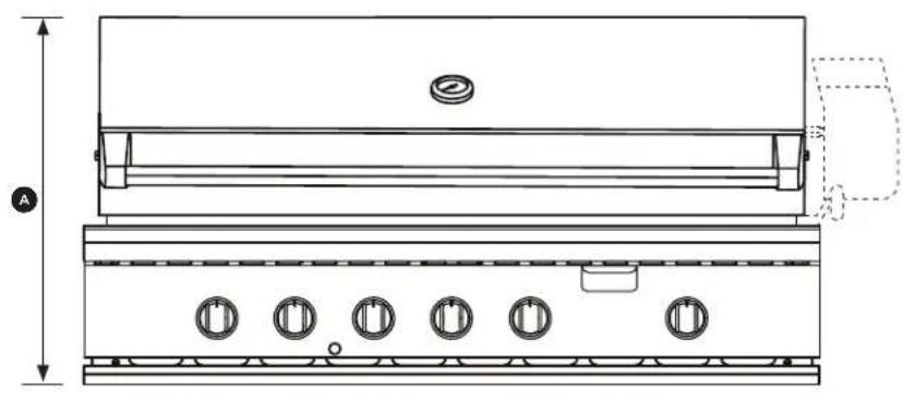
natural_image
Technical line drawing of a portable stove or oven unit with five circular vented slots and a side door (no text or labels)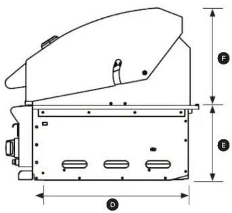
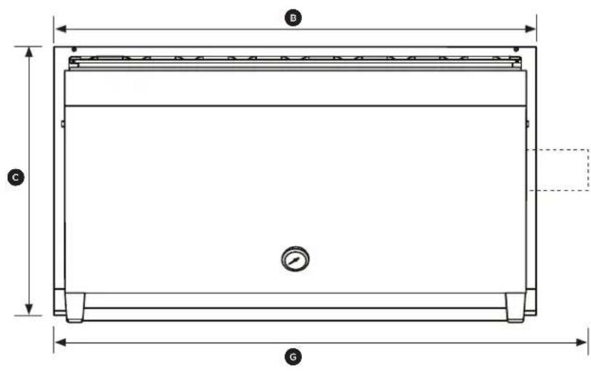
natural_image
Technical line drawing of a mechanical assembly with no visible text or symbolsEmplacement
natural_image
Technical line drawing of a two-view kitchen appliance, showing front and side views with no text or symbolsFIG. 02
DIMENSIONS POUCES (MM)
natural_image
Technical line drawing of a mechanical assembly with labeled components and directional arrows (no text or symbols)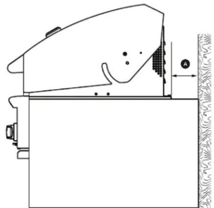
natural_image
Technical line drawing of a mechanical component with no visible text or symbolsFIG. 03
DIMENSIONS POUCES (MM)
FIG. 13
natural_image
Diagram of a conveyor belt system with an upward arrow indicating motion (no text or symbols present)natural_image
Technical line drawing of a multi-tiered mechanical component with grooves and bolts (no text or symbols)natural_image
Technical illustration of a mechanical component with grooves and hatched sections (no text or symbols)natural_image
Technical line drawing of a mechanical component with ribbed structure and mounting bracket (no text or symbols)natural_image
Technical line drawing of a metal grate structure with slats and wavy base (no text or symbols)natural_image
Mechanical assembly diagram showing a conveyor belt system with a downward arrow indicating motion (no text or symbols present)natural_image
Technical line drawing of a structural component with diagonal beams and internal channels (no text or symbols)FIG. 14
IMPORTANT!
natural_image
Technical line drawing of a mechanical assembly with no visible text or symbolsnatural_image
Diagram of a mechanical component with curved arrows indicating motion or force direction (no text or symbols)Lighting Instructions
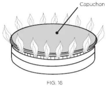
Cuisson sur gril
Grill
natural_image
Technical line drawing of a structural steel truss or support frame (no text or symbols)FIG. 17
natural_image
Technical line drawing of a mechanical assembly with three circular components and a bracket (no text or symbols)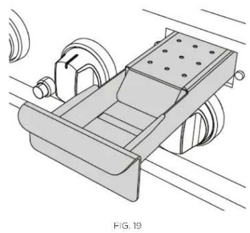
natural_image
Technical line drawing of a mechanical device with rollers and a conveyor belt, labeled as FIG. 19 (no text or symbols on the diagram itself)natural_image
Technical line drawing of a mechanical assembly with no visible text or symbolsFIG. 20
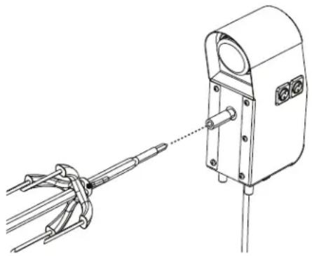
natural_image
Technical line drawing of a mechanical device with a connecting rod and cable, no text or symbols presentFIG. 21
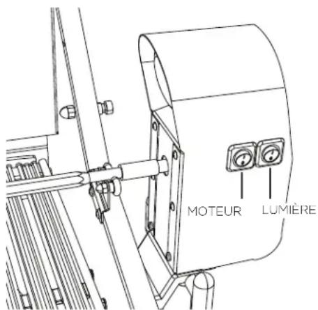
FIG. 22
IMPORTANT!
natural_image
Diagram showing mechanical components with directional arrows, no text or symbols presentnatural_image
Illustration of a rope being lifted by a hook, showing rope routing and directional arrows (no text or symbols)natural_image
Diagram of a rope knot with chains and arrows indicating motion (no text or symbols)natural_image
Technical line drawing of a mechanical device with internal grating and mounting brackets (no text or symbols)natural_image
Line drawing of a hand using a tool to adjust or install a mechanical component, with no visible text or symbols.FIG. 23
IMPORTANT!
natural_image
Technical line drawing of a mechanical assembly with no visible text or symbolsnatural_image
Technical line drawing of a mechanical device with internal components and mounting brackets (no text or symbols)natural_image
Illustration of a robotic arm with a head-mounted sensor and digital display (no text or symbols)natural_image
Diagram of a mechanical device with a magnified inset showing a rotating component (no text or symbols present)FIG. 24
natural_image
Pure technical line drawing of a mechanical component with curved paths and a base (no text or symbols)Fig. 25
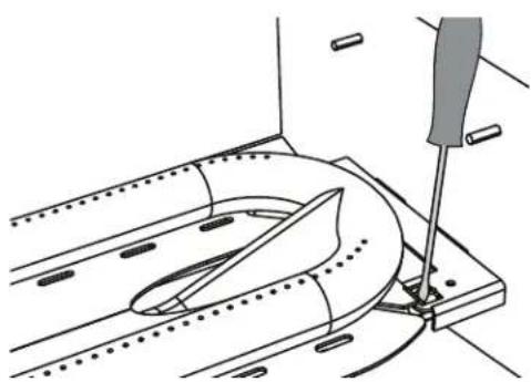
natural_image
Technical line drawing of a mechanical assembly with a tool inserted, showing no text or symbolsFig. 26
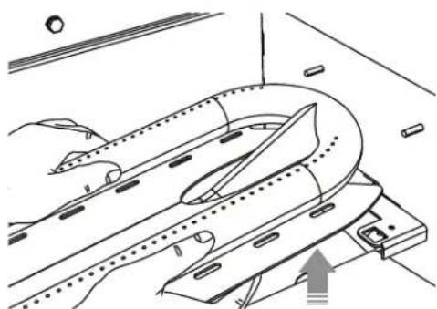
natural_image
Technical line drawing of a mechanical assembly with no visible text or symbolsFig. 27
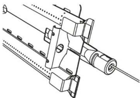
natural_image
Technical line drawing of a mechanical assembly with shafts and mounting brackets (no text or symbols)Fig. 28
Fisher & Paykel Appliances Inc.
Attention: DCS Customer Care 695 Town Center Drive, Suite 180 Costa Mesa. CA 92626-1902 USA
customer.care@fisherpaykel.com
WWW.DCSAPPLIANCES.COM
© Fisher & Paykel Appliances 2019. All rights reserved.
The product specifications in this booklet apply to the specific products and models described at the date of issue. Under our policy of continuous product improvement, these specifications may change at any time. You should therefore check with your Dealer to ensure this booklet correctly describes the product currently available.

- PROFESSIONAL GRILL
- LE GRIL PROFESSIONNEL
- WHAT TO DO IF YOU SMELL GAS
- IMPORTANT!
- WARNING!
- IMPORTANT SAFETY INSTRUCTIONS!
- Locating Grill/Built-in Clearances
- Location
- Locating Built-in Clearances
- Clearances to non-combustible construction\*
- PRODUCT DIMENSIONS INCHES (MM)
- General
- Clearances to combustible construction\*\*
- Insulated jacket
- Built-in Construction Details
- Gas Hook-up
- Gas requirements
- Total gas consumption of the grill with all burners on HI
- Natural gas built-in hook-up
- (This should be performed by a technician only)
- Operating pressure: 4.0" W.C. Supply pressure:
- To hook-up the fittings supplied with the grill
- LP Gas Hook Up (Type 1 or QCC1 regulator)
- LP cart hook-up
- LP tank requirements
- LP built-in hook-up
- Leak Testing
- Before Testing
- To Test
- Burner Adjustment
- Grill burner air adjustment
- Grill burner flame height
- To adjust
- Low flame setting adjustment
- Side burner flame height
- Radiant Assembly
- If a ceramic rod breaks
- Installer Checklist
- Lighting Instructions
- Grill lighting instructions
- Grill Match Lighting
- Side Burners Lighting Instructions
- Side Burners Match Lighting
- Side burners
- Grilling
- Grill
- Direct/indirect cooking notes
- Using the temperature gauge
- Dual-sided grates
- Grilling hints
- Cooking Chart - Main Grill
- Cooking Chart - Smoking
- Meat Temperatures
- To light the smoker burner
- Wood chips
- Preparation
- Working area
- Meat preparation
- To light the rotisserie burner before cooking
- Manual lighting
- Battery replacement
- Regulator and hose replacement
- Grill grates
- Method 1
- Method 2
- Method 3
- Drip pan and grease tray
- Ceramic rods
- Stainless steel
- Electrodes
- To remove the U-Burners for Cleaning
- Grill burner cleaning
- Orifice cleaning
- Burner alignment
- Side burners (BH1-48RS model)
- Smoker burner
- Before calling for service
- How to obtain service
- Write
- ▲ AVERTISSEMENT!
- Emplacement
- DIMENSIONS POUCES (MM)
- Cuisson sur gril
- WWW.DCSAPPLIANCES.COM
Brand : Fisher & Paykel
Model : BH1-48RS-N
Category : Barbecue