
REF31BMFIXNV - Refrigerator BERTAZZONI - Free user manual and instructions
Find the device manual for free REF31BMFIXNV BERTAZZONI in PDF.

| Product type | Combined refrigerator and freezer (top refrigerator door, bottom freezer door) |
| Brand | Bertazzoni |
| Model | REF31BMFIXNV |
| Climate class | SN (10°C to 32°C), N (16°C to 32°C), ST (16°C to 38°C), T (16°C to 43°C) |
| Power supply | 110-115 V, 60 Hz, 250 W |
| Water pressure allowed | 207-862 kPa (30-125 psi) |
| Refrigerant | R600a (flammable) |
| Main functions | Super Refrigeration, Super Freeze, Eco Mode, Ice Maker, Open Door Alarm |
| Temperature control | Digital display with Celsius/Fahrenheit selection |
| Interior lighting | LED |
| Water filter | Yes, replacement recommended every 6 months (SKU Z320380) |
| Ice maker | Automatic, with Ice Off function |
| Door reversal | Possible (right to left), kit provided |
| Adjustable feet | Yes, with front casters for moving |
| Recommended cleaning | Baking soda diluted in water, every 15 days |
| Defrost | Automatic |
| Child safety | Door lock (if present) out of reach of children |
| Spare parts | Available for 10 years after purchase |
| Recommended temperature | Refrigerator: 4°C (39°F), Freezer: -18°C (0°F) |
Frequently Asked Questions - REF31BMFIXNV BERTAZZONI
User questions about REF31BMFIXNV BERTAZZONI
0 question about this device. Answer the ones you know or ask your own.
Ask a new question about this device
Download the instructions for your Refrigerator in PDF format for free! Find your manual REF31BMFIXNV - BERTAZZONI and take your electronic device back in hand. On this page are published all the documents necessary for the use of your device. REF31BMFIXNV by BERTAZZONI.
USER MANUAL REF31BMFIXNV BERTAZZONI
| EN | INSTALLATION MANUALUSER AND MAINTENANCE MANUALREFRIGERATOR REF31BMFIXNV AND REF31BMFXNV | 3 |
| FR | MANUEL D'INSTALLATIONMANUEL D'UTILISATION ET D'ENTRETIENRÉFRIGÉRATEUR REF31BMFIXNV ET REF31BMFXNV | 39 |
| ES | MANUAL DE INSTALACIÓNMANUAL DE USO Y MANTENIMIENTOREFRIGERADOR REF31BMFIXNV Y REF31BMFXNV | 79 |
FROM THE DESK OF OUR PRESIDENT
Dear new owner of a Bertazzoni appliance,
I want to thank you for choosing one of our beautiful products for your home.
My family started manufacturing kitchen appliances in Italy in 1882, building a reputation for quality of engineering and passion for good food.
Today, our products stand out because of their unique blend of authentic Italian design and superior appliance technology. It is our mission to make products that function perfectly and bring joy to their owners.
By making beautiful products we respond to our customers' flair for good design. By making them versatile and easy-to-use, cooking with Bertazzoni becomes a real pleasure.
This manual will help you learn to use and care for your Bertazzoni appliance in the safest and most effective way, so that it can give you the highest satisfaction for years to come.
Enjoy!
Paolo Bertazzoni
President
Palo Sectorzou
IMPORTANT INFORMATION REGARDING SAFETY AND THE ENVIRONMENT 7
GENERAL SAFETY 7
INTENDED USE 8
CHILDREN'S SAFETY 8
PACKAGING INFORMATION 9
HYDROCARBON (HC) WARNING 9
SPECIFICATIONS 10
GENERAL APPEARANCE 10
TECHNICAL SPECIFICATIONS 10
INSTALLATION 11
PRODUCT DIMENSIONS 11
ELECTRICAL REQUIREMENTS 12
PLUMBING REQUIREMENTS (DEPENDING ON MODEL) 12
INITIAL USE 18
TOOLS THAT MAY BE REQUIRED 18
LEVELING THE APPLIANCE 20
REVERSING THE DOOR 21
DISPLAY PANEL SET-UP INSTRUCTIONS 26
SWITCHING CELSIUS AND FAHRENHEIT 27
FRIDGE TEMPERATURE CONTROL 27
WATER FILTER REPLACEMENT (IF APPLICABLE) 29
BEFORE USING THE REFRIGERATOR 30
WAYS TO SAVE ENERGY 30
RECOMMENDATIONS FOR THE FRESH FOOD COMPARTMENT 30
OPERATING THE APPLIANCE 31
FREEZING FRESH FOOD 31
RECOMMENDATIONS FOR STORING FROZEN FOOD 31
ARRANGING THE FOODS 31
MAINTENANCE AND CLEANING 35
PREVENTING UNPLEASANT ODOURS 35
PROTECTING PLASTIC SURFACES 35
CLEANING THE INTERIOR SURFACES 35
STAINLESS STEEL EXTERIOR SURFACES 35
CLEANING THE DOOR SEALS 35
TROUBLESHOOTING 36
APPLIANCE IS NOT WORKING CORRECTLY 36
OUDOURS FROM THE COMPARTMENTS 36
NOISE FROM THE APPLIANCE 36
THE MOTOR RUNS CONTINUOUSLY 36
A LAYER OF FROST OCCURS IN THE COMPARTMENT 36
TEMPERATURE INSIDE IS TOO WARM 37
TEMPERATURE INSIDE IS TOO COLD 37
DOORS CAN'T BE CLOSED EASILY 37
THE LIGHT IS NOT WORKING 37
HEAR WATER BUBBLING IN THE REFRIGERATOR 37
CUSTOMER CARE 38
This manual will help you to get started using your GENERAL SAFETY appliance quickly and in a safe manner.
- Please read this user manual carefully before installing and using the product.
• Always heed the applicable safety information. - Keep the user manual in an easily accessible place future use.
- Please read all of the additional documents provided with the product.
Please keep in mind that this manual may apply to a different product models.
This manual expressly indicates the differences between the various models.

WARNING
Risk of injury and property damage.

NOTE
Important information and useful tips.

The packaging materials for this product have been manufactured from recyclable materials in accordance with National Environmental Regulations.
This chapter contains safety information that will help you to prevent risks of injury or property damage. Failure to follow these instructions shall render any product warranty void.
This appliance may be used by children aged 8 or by people who have limited physical, sensory or mer capabilities and by people who lack experience and information, provided that they have been given instructions concerning the safe use of the appliance and are supervised, and that the risks have been eliminated. Children should not play with the appliance Cleaning and care should not be performed by children unless they are supervised by an adult.
Unplug the appliance if you encounter a malfunction during use.
- If the appliance malfunctions, it must not be allowed to remain on until repaired by an authorised service provider. Risk of electric shock!
- This appliance is fitted with a plug, in accordance with local standard. The plug should be suitable for use houses fitted with sockets in accordance with current specifications.
- If the fitted plug is not suitable for your socket outlet should be cut off and carefully disposed of. To avoid a possible shock hazard, do not insert the discarded pl into a socket. If in doubt contact a qualified, registered electrician.
Plug the appliance into a grounded socket that is protected by a fuse and that corresponds to the value the product's nameplate. The appliance should not be plugged into a GFCI protected outlet. Have a qualified electrician ground the appliance. Our company cannot be held responsible for damages resulting from a fail
to use the appliance with a grounded socket pursuar local regulations.
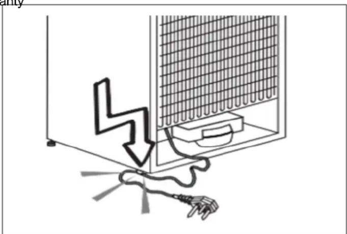
natural_image
Diagram showing a lightning bolt striking down inside a refrigerator with an electrical plug attached (no text or symbols)Fig. 1
- Make sure that the plug is not squashed or damage. Otherwise, it may cause short circuit, electric shock or overheat and event cause a fire.
• Unplug the appliance when not in use. - Never wash the appliance by pouring, daubing or spraying water onto it! Risk of electric shock!
- Never touch the plug with wet hands!
- Never unplug the appliance by pulling on the cable; on the plug itself. Always brace one hand against the socket panel while pulling the plug out.
- Do not plug in the refrigerator if the wall socket is
- Never connect your refrigerator to an energy saving device. Such systems are harmful to your appliance.
• Make sure the appliance is unplugged during installation, maintenance, cleaning and repairs.
• Make sure to have your Authorised Service Provider install the appliance and set up its electrical connection. The manufacturer cannot be held responsible for damages arising from procedures performed by unauthorised persons.
Any electrical component must be replaced or repaired by a qualified electrician or authorized service engine. Only genuine replacement parts should be used.
- Do not eat ice lollies or ice cubes immediately after take them out of the freezer compartment! This may cause an ice burn in your mouth!
- Do not touch frozen food with wet hands! It may your hands!
- Do not put bottled or canned liquid beverages in the freezer compartment. They may burst!
- Never use steam or steam cleaners to clean or d the refrigerator. Steam coming into contact with the electrical components of your refrigerator can cause short circuit or electric shock!
- Do not use mechanical devices or other means to accelerate the defrosting process; use only those recommended by the manufacturer.
- Never use refrigerator components such as the door drawers as means of support or as steps. This may cause the appliance to tip over or damage it.
- Do not damage areas where refrigerant is circulating with drilling or cutting tools. If the gas ducts in the evaporator, the tubing extensions or the surface coatings are punctured, the refrigerant could blow out, causing skin irritation and eye injuries.
- Do not cover or allow any object to block the ventilation openings in your refrigerator. - If the
- Ensure that beverages with higher alcohol content are tightly closed and store them vertically.
- Do not use aerosol sprays near the appliance; this result in a fire or explosion!
- Flammable items, products that contain flammable gases (e.g. sprays) and explosive materials should never be stored inside the appliance.
- Do not place containers filled with liquid on top of the appliance. Water spilling or splashing onto an electrical component could cause electric shock or a fire.
- Do not store items that require precisely regulated temperatures (such as vaccines, heat-sensitive medication, materials for scientific study, etc.) in the refrigerator.
fully you are not going to use the appliance for a lon nenplug it and remove the food from inside of it.
If there is a blue light on the refrigerator, do not let this light using an optical instrument.
Exposing the appliance to rain, snow, sun or wind is dangerous in terms of electrical safety.
If the appliance has a mechanical control system (thermostat), wait for 5 minutes to plug the appliance back in again after unplugging.
iOs. not operate the appliance without the cover of in lighting.
To avoid eye injury, do not look directly into the LE located in the refrigerator compartment. If it is not
dfunctioning correctly, consult a qualified, registered electrician.
Do not overload the refrigerator. Objects in the refrigerator may fall when the door is opened, causing injury or property damage. Placing objects on top of appliance may give rise to a similar hazard.
tidkthe refrigerator has a door handle, do not use that handle to move it. The handle might be loose.
Be careful not to place your hand or any other bod in the moving parts of the refrigerator.
Do not place your hand or any other foreign object the ice machine while it is operating.
INTENDED USE
This product has been designed for domestic use. It must not be used in any way other than that for w is intended. It is not suitable for commercial use.
,It must be used only for storing food.
The manufacturer shall not be held liable for any damages resulting from improper use or transport.
Original spare parts will be available for 10 years following the product's purchase date.
CHILDREN'S SAFETY
- If there is a lock on the door of the appliance, the key should be kept out of reach of children.
Do not allow children to play with the product.

CAUTION
Before disposing of your old refrigerator or freezer:
• Children may get trapped inside.
- Remove the doors.
- Leave the shelves in place to prevent children from climbing inside the product easily.
PACKAGING INFORMATION
The packaging materials for this product have been manufactured from recyclable materials in accordance National Environmental Regulations. Do not dispose of packaging materials with ordinary household waste or types of waste. Take these materials to a recycling designated by local authorities.
HYDROCARBON (HC) WARNING
Your product's cooling system contains R600a. This gas is programmable. Therefore, be careful not to damage the cooling system or the tubing during use or transportation. If damaged, keep the appliance away from potential source location, which could cause it to catch fire, and vent the room where the appliance is placed.

CAUTION
Risk of Fire or Explosion:
• This product uses flammable refrigerant.
- Do not use mechanical devices to defrost the refrigerator.
- Do not use chemicals for cleaning.
• Do not pierce the refrigerant tubing.
- If the refrigerant tubing is pierced, it must be repaired only by licensed service personnel.
- Please consult the maintenance and use manual before cleaning the product. All safety instructions must be followed.
- Dispose of the product in accordance with federal or local regulations.
- Should any damage be evident when unpacking the refrigerator, do not plug in the appliance but contact the shop immediately from which you purchased it. Keep all packing materials.

NOTE
If the appliance is damaged or if you see gas leak, please keep away from the gas as it may cause ice burn if it comes into contact with the skin. Thoroughly ventilate the room in which the appliance is situate

NOTE
The type of gas used in the product is I on the rating label, which is located on the left interior wall of the refrigerator.

WARNING
Never attempt to burn the product as a means of disposal.
GENERAL APPEARANCE
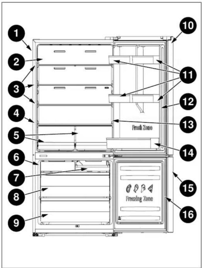
Fig. 2
1) Cabinet
10) Fridge door
2) Wind channel
11) Small rack
3) Glass shelf
12) Fridge gasket
4) Crisper cover
13) Control panel
5) Fruit & Vegetable Crisper
14) Lower rack
6) Ice maker (depending on model)
15) Freezer door
16) Freezer gasket
7) Upper freezer drawer
8) Middle freezer drawer
9) Lower freezer drawer

NOTE
The figures in this user manual are schematic and may not match the product exactly. If your product does not have the parts described, the information applies to other models.
TECHNICAL SPECIFICATIONS
| Permissible water pressure 30-125 psi (207-862 kPa) | |
| Electrical connection | 110-115 V/60 Hz |
| Rated input power 250 W | |
| Climate class SN-N-ST-T | |
| CLIMATE CLASS | AMBIENT TEMPERATURE | |||||
| SN | +10°C | to | +32°C | |||
| N | +16°C | to +32°C | ||||
| ST | +16°C | to | +38°C | |||
| T | +16°C | to +43°C | ||||

NOTE
This appliance may not work properly if being left at a temperature above or below the indicated climate class range for a lon period of time.

NOTE
If the voltage fluctuates exceeding the upper limit, A. C. automatic voltage regulator of more than 350 W should be applied to the refrigerator for safety use.
Place the device in a dry place to avoid damage due to moisture.
Keep the appliance out of direct sunlight, rain or frost. Keep the appliance away from heat sources, such as stoves, fires or stoves.
PRODUCT DIMENSIONS
TOP VIEW

Fig. 3
A. 52" 1/2 (1333)
E. 56" 5/8 (1439)
B. 34" 9/16 (878)
F. 90^
C. 1" 1/32 (26)
G. 130°
D. 3" (76)
FRONT VIEW
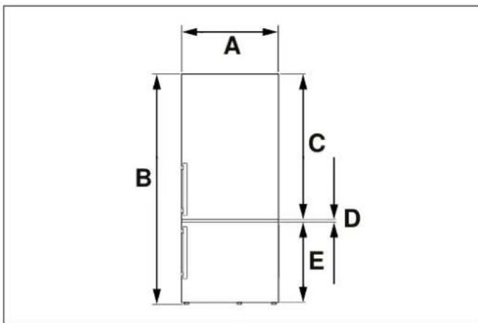
Fig. 4
A. 31" 1/4 (794)
B. min. 65" 1/2 (1664) - max. 66" 5/8 (1692)
C. 40" 5/16 (1024)
D. 7/16" (11)
E. 25" 13/16 (656)
SIDE VIEW
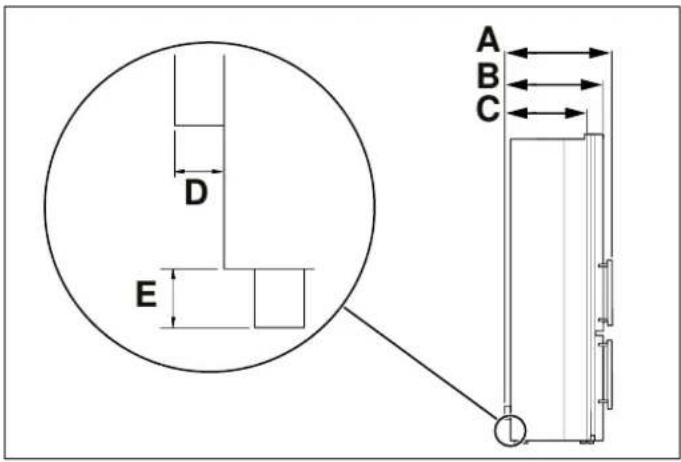
Fig. 5
A. 29" 3/4 (756)
B. 27" 1/2 (698)
C. 24" 1/2 (610)
D. 1 / 2'' (13)
E. 1" 1/8 (28)

NOTE
To improve the efficiency of the of the cooling system and save energy, it is necessary to maintain a good ventilation around the appliance appliance for heat dissipation. For this reason, it is necessary to have sufficient free space around the around the refrigerator.

NOTE
It is recommended to leave a clearance of at least 2" from the wall, at least 3/8" from the top, at least 3/8" from the sides to the walls, and a clearance in front to allow the door to open 130°.
ELECTRICAL REQUIREMENTS
Please check the electrical standards and local codes before installing the appliance.
PLUMBING REQUIREMENTS (DEPENDING ON MODEL)
CONNECTING THE WATER SUPPLY
The appliance must be applied with single phase alternating current of 110-115 V (Volts), 60 Hz (Hertz) if refrigerator. A water filter removes unwanted particles voltage fluctuates exceeding the upper limit, A.C. automatic your water. It does not, however, sterilize or destric voltage regulator of more than 350 W should be applied to microorganisms. the refrigerator for safety use.
An Ice Maker and/or water filter may be installed on y When the refrigerator. A water filter removes unwanted particles of a micr your water. It does not, however, sterilize or destrated into other organisms.

WARNING
Do not use any extension cord or multiple sockets which could cause overloading wiring circuits and could cause a fire.
Always plug the appliance in its own individual electrical socket that has a voltage corresponding to that indicated the rating plate.
For purification and sterilization, it may be necessary to purchase a water purifying system.
of For the ice maker to operate properly, the appliance m be connected to a drinking water supply.
The maximum inlet water pressure is 700 KPa; and the or minimum inlet water pressure is 207 KPa.

WARNING
The water connection must be carried out by a qualified plumber. Operation outside the water pressure range may cause malfunction and severe, damaging water leaks. Under normal conditions, a 200cc (5.75 oz.) cup can be filled in about 10 seconds. If the refrigerator is installed in a area with low water pressure (below 30 psi), a booster pump may be installed compensate for lower inlet pressures.
The following tools and parts (not supplied) will be nee
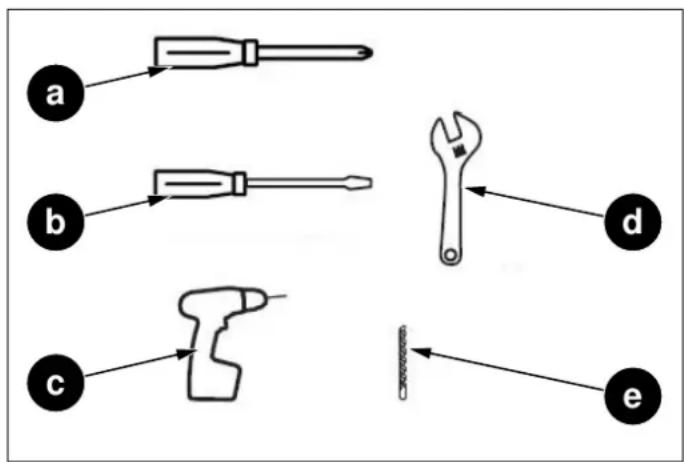
Fig. 6
a. Phillips screwdriver
b. Flat-blade screwdriver
c. Drill
d. 1/2" or adjustable wrench
e. 1/4" drill bit
flowchart
graph TD
    f --> g
    g --> h
    h --> i
    i --> g

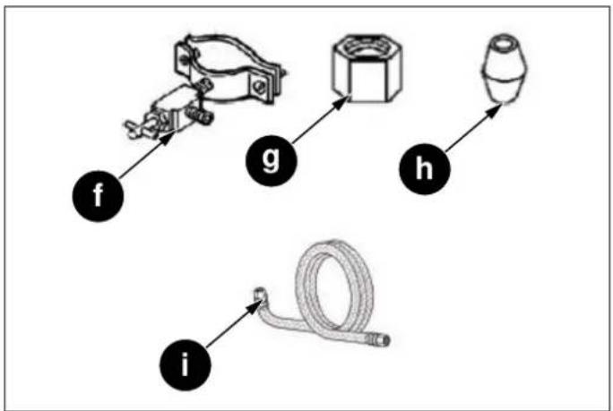
Fig. 7
Fig. 8
f. 1/4" saddle type shutoff valve (1)
g. 1/4" compression nut (1)
h. Ferrule (sleeve) (1)
i. Water supply installation kit

NOTE
Use tubing supplied with the refrigerator and/or all new tubing. Do not use old tubing.
1) All work must comply with local plumbing code specifications and requirements.
2) Connect to cold water line with water pressure between 30 and 125 psi.
3) Take caution to not contaminate water pipes. The size of pipes is 1/4".
4) The product comes with the filter. Please connect the water filter referring to the filter instructions.
1) Shut off power supply.
2) Shut off water main supply.
3) In the cold-water supply line, drill a 14 " hole in the vertical section or horizontal (top of pipe). Then install the saddle-type shutoff valve. Ensure that the outlet end is securely positioned in the 14 " hole.
4) Securely connect the 14 " extension
a. Cold water line
b. Pipe clamp
c. Shutoff valve
d. Water line installation kit
5) Place other end of tubing in sink or empty containe Turn water supply back on and open the shutoff val flush any contaminants out. Run water until clear.
6) Close the shutoff valve.
CONNECTING THE WATER SUPPLY TO FILTER INLET
The items needed to complete the connection can be found at your local hardware store.

CAUTION
Do not use without the molded end (bulb) of the plastic tubing.
You can use plastic tubing, copper tubing, or stainless tubing as the water line installation kit.
steel you are using stainless steel tubing, slip the compression nut on the stainless tubing (not supplied).
| PLASTIC TUBING | COPPER TUBING | STAINLESS STEEL TUBING |
| 1/4" plastic tubing molded end (bulb) | 1/4" copper tubing | 1/4" Stainless tubing |
| 1/4" compression nut (1) | 1/4" compression nut (1) | 1/4" compression nut (1) |
| Ferrule (2) |

flowchart
graph TD
    A --> a
    B --> c
    C --> f
    d --> e
    e --> g
    a --> b
    b --> A
    c --> b
    c --> B
    f --> C
2) Tighten the compression nut onto the compression fitting. Do not over-tighten the compression nut.
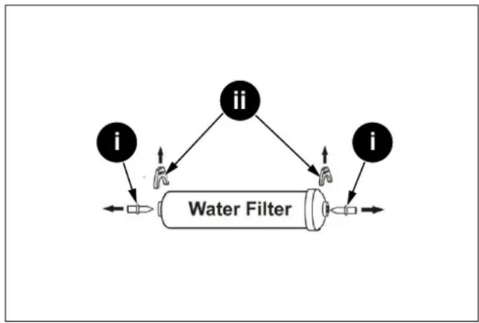
3) Connect the 1/4" tube (assembled with compression r and compression fitting) to water filter inlet, following these steps below:
3.1) Take two clips out, then pull out two stoppers of the water filter.
flowchart
graph TD
    i1["i"] --> A["Water Filter"]
    ii1["ii"] --> A
    ii2["ii"] --> A
    i2["i"] --> A
Fig. 10
Fig. 9
a. Compression nut (1/4") (not supplied)
b. Ferrule
c. Molded end (bulb)
d. Compression nut (assembled)
e. Compression fitting (assembled)
f. Compression nut (1/4")
g. 1/4" tube (assembled)
A. Copper tubing (not supplied)
B. Plastic tubing (not supplied)
C. Stainless steel tubing (not supplied)
1) Connect the water supply line to the compression fitting (assembled with a 1/4" tube, included in refrigerator).
- If you are using copper tubing, slip the compression nut (not supplied) and ferrule (not supplied) on the copper tubing (not supplied).
- If you are using plastic tubing, insert the molded end (bulb) of the plastic tubing into the compression fitting.
i. Stopper
ii. Clip
3.2) Fully insert the 1/4" tube into the inlet of the filter.
3.3) Insert a clip in the proper position as the figure shown below and confirm that the clip holds the 4" tube firmly.
flowchart
graph TD
    A["A"] --> E["E"]
    B["B"] --> E["E"]
    C["C"] --> D["D"]
    D["D"] --> E["E"]
    E["E"] --> F["F"]
    F["F"] --> G["G"]
    H["H"] --> E["E"]
    F["F"] --> G["G"]
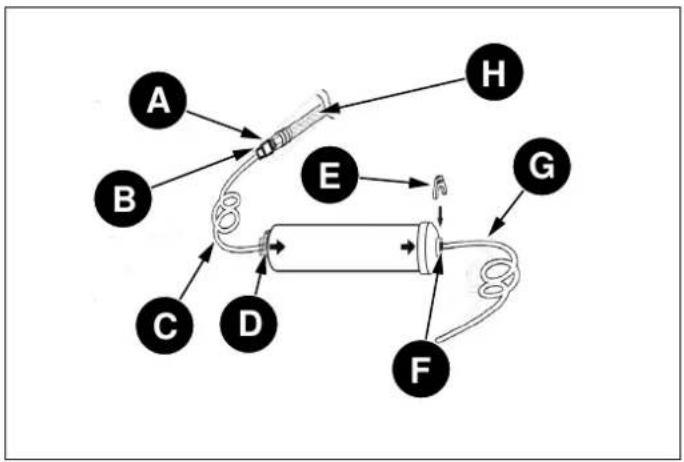
Fig. 11
A. Compression fitting (assembled)
B. Compression nut (assembled)
C. 1/4" tube (assembled)
D. Inlet
E. Clip
F. Outlet
G. Water line (1/4")
H. Water line installation kit
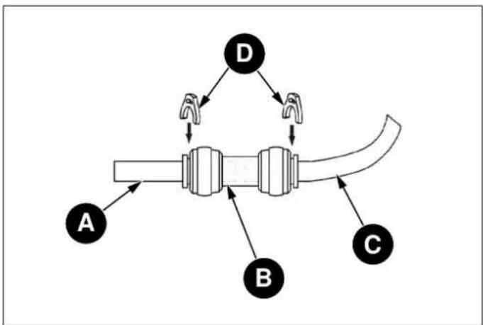
CONNECTING THE WATER FILTER OUTLET TO REFRIGERATOR
A connector, two clips and a water line (1/4") are proven with refrigerator for installation.
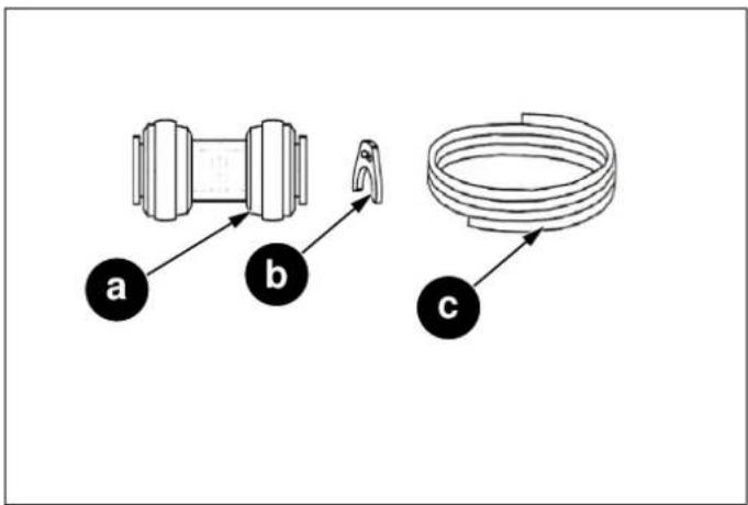
Fig. 12
a. Connector
b. Clip
c. Water line (1/4")
1) Fully insert one head of the water line (1/4") into tl outlet of water filter.
2) Insert a clip in the proper position as the figure shows below and confirm that the clip holds the water line firmly.

flowchart
graph TD
    A["A"] --> E["E"]
    B["B"] --> E["E"]
    C["C"] --> D["D"]
    D["D"] --> E["E"]
    E["E"] --> F["F"]
    F["F"] --> G["G"]
    G["G"] --> H["H"]
Fig. 13

flowchart
graph TD
    A["A"] --> B["B"]
    B --> C["C"]
    C --> D["D"]
    D --> A
    style A fill:#f9f,stroke:#333
    style B fill:#ccf,stroke:#333
    style C fill:#cfc,stroke:#333
    style D fill:#fcc,stroke:#333
Fig. 14
A. Compression fitting (assembled)
B. Compression nut (assembled)
C. 1/4" tube (assembled)
D. Inlet
E. Clip
F. Outlet
G. Water line (1/4")
H. Water line installation kit

NOTE
In order to fix the water filter at the proper position and avoid over bending the water line (1/4"), you should determine the distance from the shutoff valve to the filter mounting location previously. Then cut the water line (1/4") as required length.

NOTE
The water line (1/4") length should be less than 5 m. If the water line is too long (>5 m), the ice and cold water content m be affected due to insufficient water pressure.

NOTE
The water line must be fully inserted into the center of the connector to prevent wall leaking.
3) After connecting the water line (1/4"), please turn on the shutoff valve to flush the filter for 5 minutes before use.

NOTE
The initial dark discoloration of water is normal.
4) Connect the water line (1/4") with refrigerator by a connector.
4.1) Fully insert the other head of the water line (1/4") into the connector.
4.2) Fully insert the water line of the refrigerator (at the right of the compressor room) into the connector.
4.3) Insert two clips in the install pack as shown below, and then confirm that each clip holds the water line firmly.
FIXING THE WATER FILTER
To fix the water filter, follow these steps below.
1) Determine the location to mount the water filter.

WARNING
The water filter must be held upright as shown in the figure. It is critical to connect the water line tube into the filter inlet and outlet correctly.

NOTE
The water filter should be mounted on the wall in a readily accessible area i case of replacement.
5) After connecting the water supply, water filter, and the refrigerator, water connecting system layout shows in below.

NOTE
Do not mount the filter onto the refrigerator! Coolant pipes might be pierced!
2) Determine the distance from the shutoff valve to the filter mounting location, and the distance from the filter mounting location to the refrigerator. The shutoff valve must also be installed in an accessible location.
3) To avoid over bending the water line, cut the water line (1/4") as required length according to the determined distance previously.
4) Mount the filter holder onto the wall by using a screwdriver and attach the water filter.

Fig. 15
a. Filter holder
b. Screw
c. Water line (1/4")
d. Outlet
e. Filter holder
f. Filter
g. Inlet
h. 1/4" (assembled)
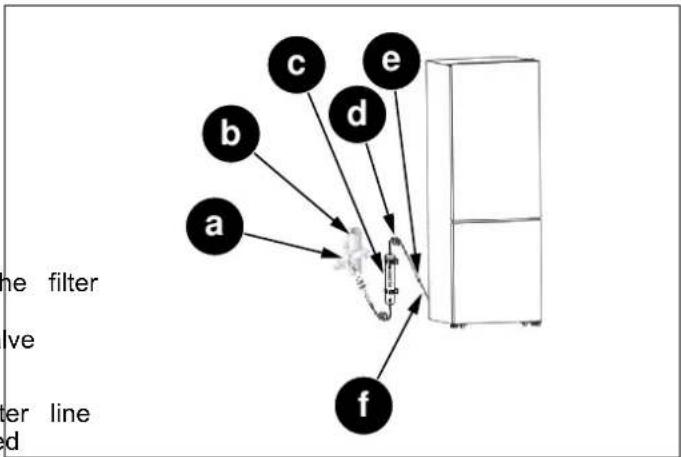
Fig. 16
a. Shutoff valve
b. Cold water line
c. Water filter
d. Water line (1/4")
e. Connector
f. Water line of the refrigerator
- If you choose to use without the water filter.
flowchart
graph TD
    A["A"] --> B["B"]
    B --> C["C"]
    C --> D["D"]
    D --> A
    style A fill:#f9f,stroke:#333
    style B fill:#ccf,stroke:#333
    style C fill:#cfc,stroke:#333
    style D fill:#fcc,stroke:#333
Fig. 17
A. Water line of the refrigerator
B. Connector
C. 1/4" tube(assembled)
D. Clip
Follow up inspections apply to both units with and wINITIAL USE filters.

NOTE
It is recommended to employ a qualified person to install the water system.
Before using the appliance, make sure that all preparati have been made according to the instructions provided the manual.
Clean the interior of the refrigerator as recommended the "Maintenance and Cleaning" section. Before you turn on the refrigerator, make sure that the interior is dry.

NOTE
If you have to repair or disassemble the water line, cut off the ends of water line 4") to make sure you get a snug, leak-f connection.
Plug the refrigerator into a grounded socket 4 hours after the refrigerator is installed. This will allow the refrigerator to flow back into the compressor. The interior lighting comes on when the refrigerator door is opened.
Run the refrigerator for 6 hours before placing any f in it and do not open its door unless it is necessary.

NOTE
It is suggested to change the water filter every 6 months to ensure the best possible water quality. Filters may be purchased at Encompass Parts (https:// encompass.com/) under the SKU Z320380. After installing, check the installation thoroughly for leaks.

NOTE
You will hear a noise when the compressor starts up. The liquids and gases sealed within the refrigeration system may also cause noise, even if the compressor is no running. This is quite normal.

WARNING
After turning on the shutoff valve, make sure that there is no leakage at all connection points of the water lines. If there is a leakage, turn off the shutoff valve immediately and tighten the connector or make the water lines fully inserted into the connector.

NOTE
The front edges of the refrigerator may feel warm. This is normal. These areas are designed to be warm in order to prevent condensation.

WARNING
After powering on the refrigerator, let the ice maker make ice for one to two days, then throw out the first one or two buckets of ice to make sure that all impurities have been removed from the water lines.

NOTE
The power plug must be accessible when the appliance is installed.

WARNING
Do not pull hard on the water lines, it may damage the water system.

WARNING
When reversing the door, the appliance must not be connected to the Power, Ensure that the plug is removed from the power socket.

WARNING
The water line should not be pressed by heavy things and should not bend too much.

NOTE
If required, you may lay the refrigerator or its back in order to gain access to the b you should rest it on soft foam packaging similar material to avoid damaging the backboard of the refrigerator.

CAUTION
The warranty does not cover any parts, labor, or damage to property caused by improper installation, use, maintenance, repair or service.
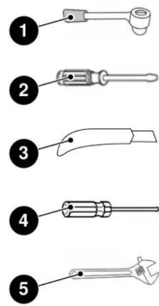
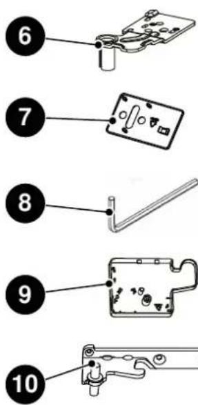

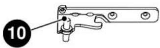
Fig. 18
NOT PROVIDED ADDITIONAL PARTS (IN THE PLASTIC BAG)
1) Wrench /8 mm
2) Thin-blade screwdriver
3) Thin blade (utility knife e.g.)
4) Cross screwdriver
5) Monkey wrench
6) Upper Hinge-Left
7) Screw Hole Cover right
8) Allen Wrench /4 mm
9) Upper Hinge Cover-left
10) Middle Hinge-left
11) Left stop Block for fridge door
12) Left Door Stopper for fridge door
13) Left stop Block for freezer door
14) Left door Stopper for freezer door
LEVELING THE APPLIANCE
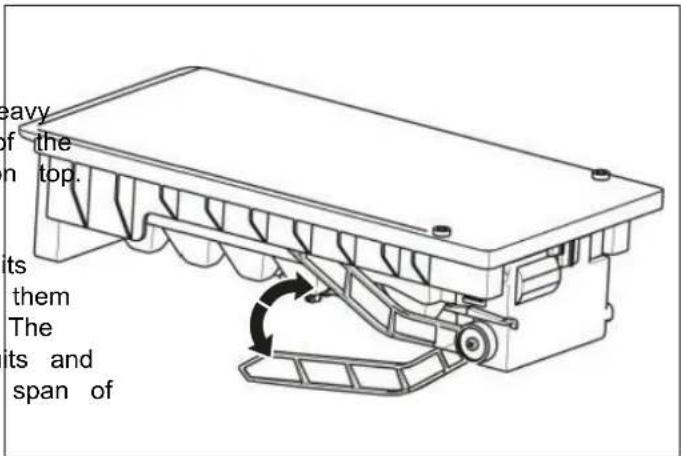
- For sufficient leveling and air circulating in the lower rear section of the appliance, the bottom feet may need to be adjusted. You can adjust them manually by hand or by using a suitable spanner.
- To allow the doors to self-close, tilt back the top backwards at about 15 mm by turning the adjustable feet.
- Whenever you want to move the appliance, remember to turn the feet back up, so that the appliance can roll freely. Reinstall the appliance when relocating.

Fig. 19
A. 10 - 15 mm
1 Front roller
2 Rear roller

Fig. 20
1) Adjustable bottom feet

WARNING
For proper installation, this refrigerator must be placed on a level surface of hard material that is the same height as the rest of the flooring. This surface should be strong enough to support a fully loaded refrigerator.

WARNING
The rollers, which are not castors, should be only used for forward or backward movement. Moving the refrigerator sideways may damage your floor and the rollers.

WARNING
It is advisable to adjust both the bottom feet until they touch the ground after placing the refrigerator.

Fig. 21
REVERSING THE DOOR
The opening side of the door can be changed, switching from the right side (as supplied) to the left side if nec
2) With the door closed, unscrew 1 and remove upper hinge cover-right 2 from the right-top corner of cabin. Remove the reed switch 4 and the humidity sensor from the cabinet and upper hinge cover-right 2, and install them on the upper hinge cover-left (provided in the plastic accessory bag). Unscrew the three screws which are used for fixing the upper hinge-right (see picture below).

WARNING
When reversing the door, the appliance should not be connected to the power supply. Make sure the plug is removed the power outlet.


NOTE
If necessary, you can lay the refrigerator on its back to access the base. It is advisable to lay it on soft foam packing or similar material to avoid damaging the back panel of the refrigerator.
To reverse the door, proceed as follows:
1) Place the refrigerator upright and open door to remove all the door shelves (to avoid damage) and then close the door.
Fig. 23
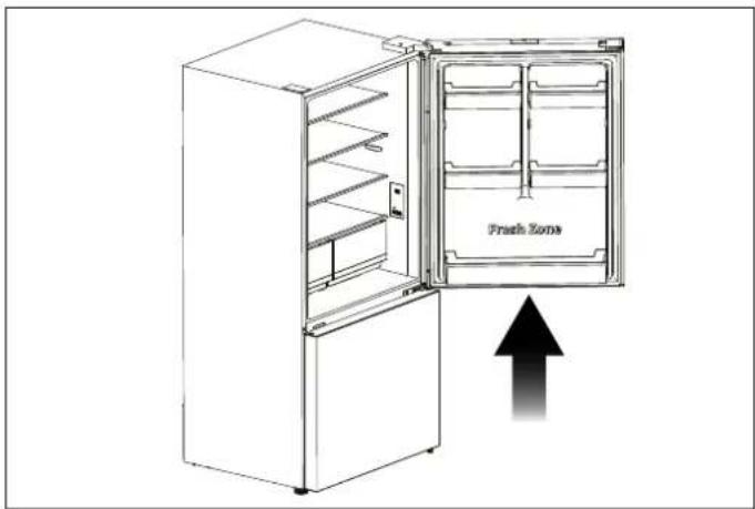
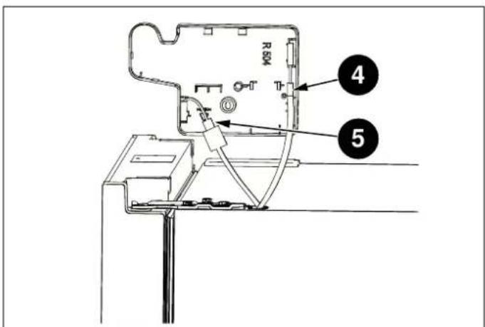
Fig. 22
Fig. 24

CAUTION
Slightly squeeze the door shelves from both sides toward the center and toward the door, and then remove them by pushing upward.
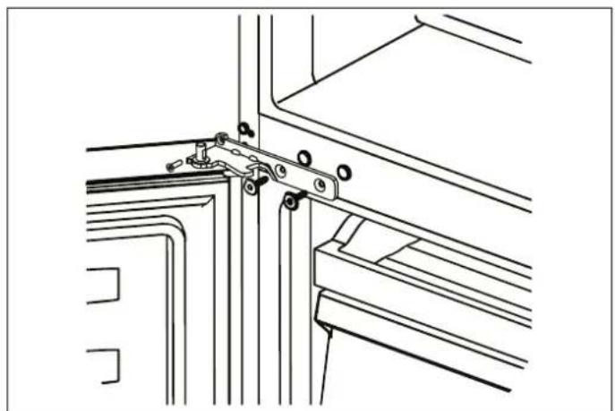
3) Remove the upper hinge-right (please hold upper by hand when installing).
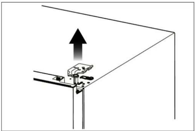
natural_image
Diagram of a mechanical clamp or bracket assembly with an upward arrow indicating force or direction (no text or symbols present)Fig. 25
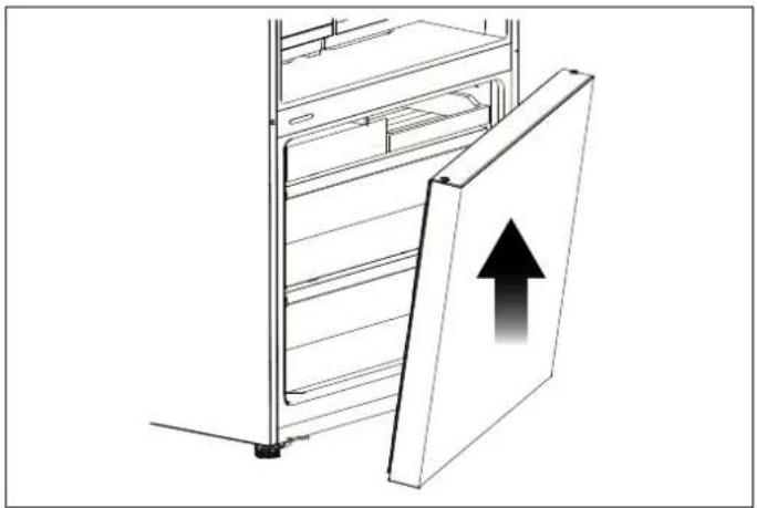
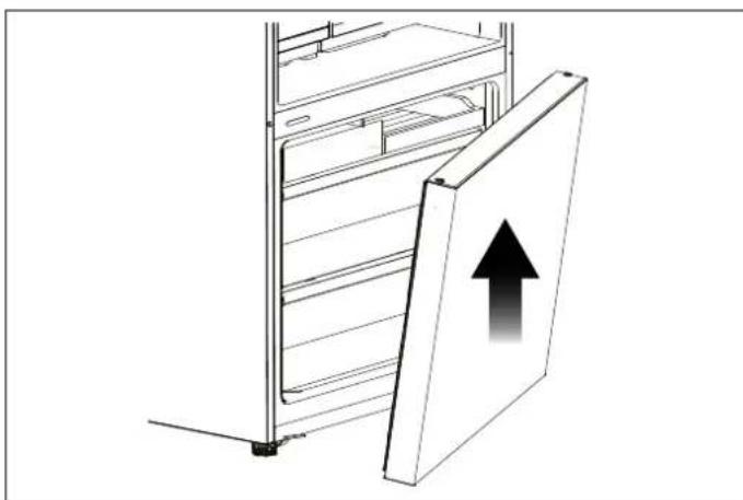
4) Remove the upper door from the middle hinge by carefully lifting the door straight up. Then place the upper door on a smooth surface with its panel upwards.
d5)prUnscrew the two screws 6, then take out the right stopper for fridge door 7 and the right stopper block fridge door 8, install the replacement left door stoppe and left stopper block 10 (provided in the plastic accessory bag) to the left side with screws 6. Keep and 8 with the appliance for future reference.
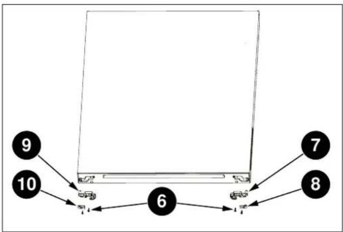
flowchart
graph TD
    A["9"] --> B["10"]
    B --> C["6"]
    C --> D["7"]
    C --> E["8"]
Fig. 27
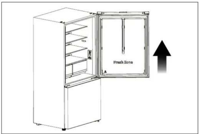
Fig. 26
6) Use the Allen wrench (provided in the plastic access). Place the lower door on a smooth surface with its bag) to unscrew the screws used to fix the middle upwards. Unscrew the two screws 6, then take out the hingeright and remove middle hinge -right. Then remove right door stopper for freezer door 11 and the right the lower door. stopper block for freezer door 12, install replacement
natural_image
Technical line drawing of a mechanical bracket assembly (no text or symbols)Fig. 28

flowchart
graph TD
    A["Device 13"] --> B["Component 14"]
    B --> C["Component 6"]
    C --> D["Component 12"]
    D --> E["Component 11"]
    style A fill:#f9f,stroke:#333
    style B fill:#ccf,stroke:#333
    style C fill:#cfc,stroke:#333
    style D fill:#fcc,stroke:#333
    style E fill:#ffc,stroke:#333
Fig. 30
natural_image
Diagram of a refrigerator with an upward arrow indicating storage or ventilation (no text or symbols present)Fig. 29
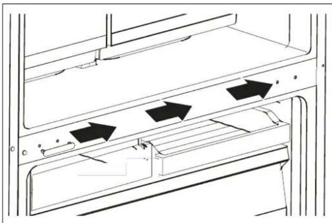
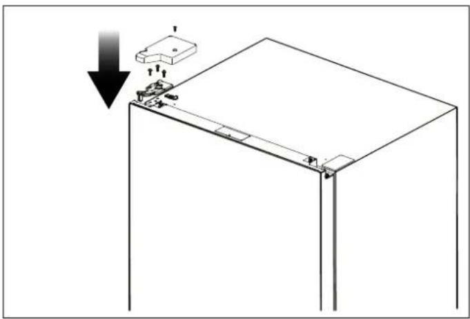
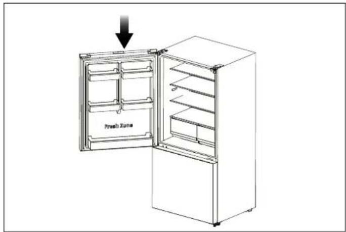
8) Install the screw hole cover-right 15 (provided in the plastic accessory bag) to the right-top corner of cabir Remove screw hole cover-left 16 from the left-top co of cabinet with the thin-blade screwdriver and put the screw hole cover-left and upper hingeright into the plastic accessory bag for future reference.

Fig. 31
9) Change screw hole covers and screw on middle plate from left to right (as shown in figure below).
natural_image
Technical line drawing of a door frame with arrows indicating movement or force (no text or symbols)Fig. 32
ct00perLie the refrigerator backwards, Remove adjustable bottom feet part 17, remove 3 self-tapping screws 18 from the lower hinge -right 19. Unscrew the lower h right axis then install it on the reverse hole site, an tighten into position (change it into lower hinge left). Install the lower hinge-left to the left-bottom corner of cabinet, Then fix it with 3 screws, finally install adjustable bottom feet part 17 on the left-bottom corr and right-bottom corner of cabinet.
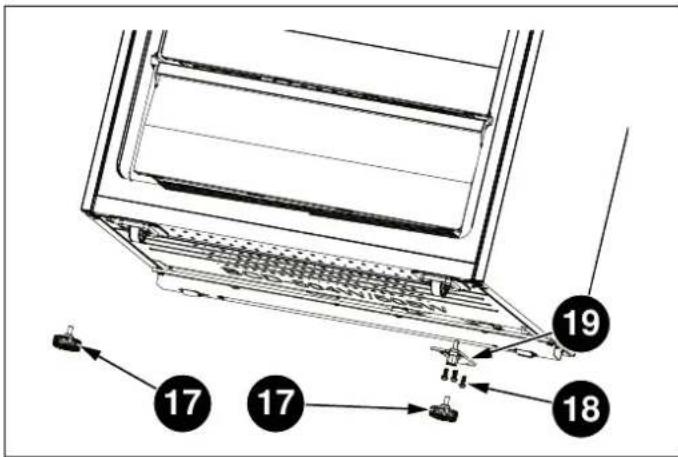
Fig. 33

Fig. 34
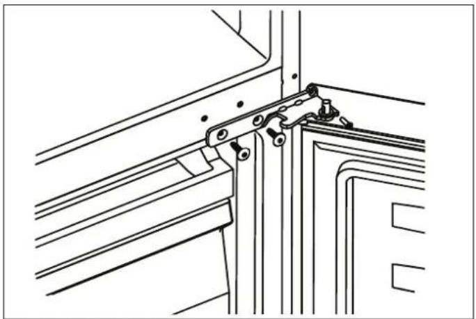
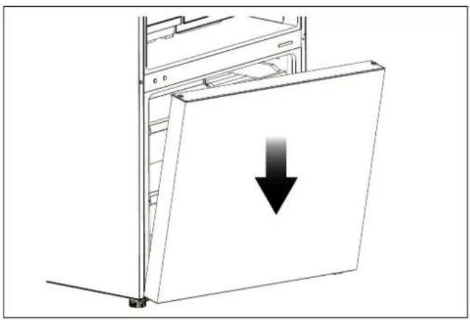
11) Stand the refrigerator upright and carefully slot the 12) Carefully slot the upper door onto the middle hinge lower door onto the lower hinge-left pin and hold it and hold in position. Move the upper door to an position. Install middle hinge-left (provided in the plastic appropriate position, adjust the upper hinge-left accessory bag) and ensure the lower door in place. (provided in the plastic accessory bag) and upper do
natural_image
Diagram of a computer tower with a downward arrow indicating compression or disassembly (no text or symbols present)Fig. 35
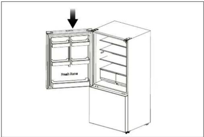
Fig. 37

natural_image
Technical line drawing of a mechanical bracket assembly (no text or symbols)Fig. 36
13) Assemble the upper hinge cover-left to match the hinge. Install the door racks to original position. Keep upper hinge cover-right with the appliance for future reference.
natural_image
Technical diagram of a mechanical assembly with a downward arrow indicating a component (no text or symbols present)Fig. 38
Use the appliance according to the following instructions.
flowchart
graph TD
    A["2°C"] --> B["-80°F"]
    C["4°C"] --> D["Super Cool"]
    E["6°C"] --> F["Super Cool"]
    G["8°C"] --> H["Eco"]
    I["10°C"] --> J["Ice Off"]
    K["11°C"] --> L["Ice Off"]
    M["1"] --> N["Super Freeze"]
    O["3"] --> P["Super Freeze"]
    Q["5"] --> R["Super Freeze"]
    S["7"] --> T["Super Freeze"]
    U["9"] --> V["Ice Off"]
    W["11"] --> X["Ice Off"]

Fig. 40 REF31BMFXNV
Fig. 39 REF31BMFIXNV
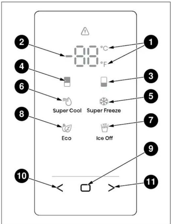
1) Celsius and Fahrenheit Indicator
7) Ice Off Icon (depending on model)
2) Temperature Area
8) Eco Icon
3) Freezer Compartment Icon
9) Confirm Control
4) Fridge Compartment Icon
10) Function Selector Control: Left Control
5) Super Freeze Icon
11) Function Selector Control: Right Control
6) Super Cool Icon
12) Alarm Icon (depending on model)

NOTE
Once the appliance is powered on, all icons on the display panel will be lit for 3 seconds with a buzzer sound.

NOTE
All the icons will go off on the condition all keys untouched and all doors closed for one minute.

NOTE
The control panel will light up when the door is open or you touch any button.

NOTE
Setting the refrigerator running at high temperature will accelerate food decomposition. For optimum food preservation, we recommend that when starting the refrigerator for the first time temperature of fridge is set to 4°C (3 and that of the freezer to -18°C (0°F
1) Press < or > repeatedly until the Fridge icon blinks.
2) Press the Confirm Control ☐" for the first time, and the freezer icon will be always on. After that, press Confirm Control repeatedly to cycle through the available temperature settings, from -14°C to -24°C if you have set temperature type to Celsius.
If you have set temperature type to Fahrenheit, the temperature settings cycle will be from 7^ F to -11^ F.

CAUTION
The temperature only means the average temperature of the whole refrigerator cabinet. Temperatures inside each compartment may vary from those displayed on the panel, depending on how much food is stored and where the refrigerator is placed. In addition, the act temperature from higher room and lower room will be different.

NOTE
With each press of the button, the temperature drops by one degree
SWITCHING CELSIUS AND FAHRENHEIT
1) Press < or > repeatedly until the indicator °C or °F blinks.
2) Press the Confirm Control □ for the first time, and °C or °F will be always on. After that, each time you Confirm Control □, the temperature will be switched between °C and °F, and the temperature setting the corresponding unit will be displayed in the temperature area.
FRIDGE TEMPERATURE CONTROL
1) Press < or > repeatedly until the Fridge icon blinks.
2) Press the Confirm Control for the first time, and the Fridge icon will be always on. After that, press the Confirm Control repeatedly to cycle through the available temperature settings, from 8°C to 2°C if you have set temperature type to Celsius.
If you have set temperature type to Fahrenheit, the temperature settings cycle will be from 46^ F to 36^ F.
SUPER COOL
The Super Cool feature helps to keep food stored in the refrigerator at the setting temperature during periods of high usage, large grocery loads, or temporarily warm ro temperatures. The Super Cool feature lowers the temperature in the fridge compartment to 2°C (36°F) to food.
press the
1) Press < or > repeatedly until the Super Cool icon value of links.
2) Press the Confirm Control □ to turn the Super Cool function on or off. When the Super Cool function is turned on, the 🔊 icon lights.
3) When setting fridge temperature, the Super Cool function will turn off and the temperature setting will revert back to the previous setting.
NOTE
Super Cool will automatically turn off after hours.

NOTE
With each press of the button, the temperature drops by one degree.
SUPER FREEZE
DOOR OPEN ALARM
This Super Freeze feature helps to keep the food s the freezer as the setting temperature during periods high usage, large grocery loads, or temporarily warm temperatures. The Super Freeze feature lowers the temperature in the freezer compartment to -24°C (-11 freeze the food faster.
of the fridge or freezer door is opened for longer than 2 of minutes, the control panel will display dr! the icon v blank and the buzzer will sound 3 times every minute 5 minutes. Pressing and holding □ and > buttons at the same time for three seconds during door alarm, the ⚠icon will be on and buzzing will stop. Closing the fridge door, the ⚠icon will go off and buzzing will stop.
1) Press or repeatedly until the Super Freeze icon blinks.
ICE CONTROL (DEPENDING ON MODEL)
2) Press the Confirm Control to turn the Super Freeze function on or off. When the Super Freeze function is turned on, the icon lights. This
This ^ICE icon shows the condition of the ice maker function (1) Press < or > repeatedly until the Ice Control icon will ^ICE blinks.
3) When setting freezer temperature, the Super Freeze1 function will turn off and the temperature setting will revert back to the previous setting.
2) Press the Confirm Control to turn the Ice Maker function on or off. When the Ice Maker function is turned on, the ☑ icon is off; When the Ice Maker function is off, the ☑ icon is on.

NOTE
Super Freeze will automatically turn off after 52 hours.
DEMO MODE
When you selecting the Super Freeze function, ensure there are no bottled or canned drinks (especially carbonated drinks) in the freezer compartment. Bottles cans may explode.
Demo mode is for store display, and it prevents the refrigerator from generating cool air. In this of Cooling Off Mode, the refrigerator may seem like it is working but i not make cool air.
ECO
The Eco feature makes the refrigerator work in an energy saving mode which is useful for reducing energy consumption when you are away.
If you enter the Demo mode, the temperature area will show OF. To switch off Demo mode, press and hold < and > buttons at the same time for 5 seconds and the buzzer gave a long sound.
1) Press < or > repeatedly until the Eco icon blinks.
2) Press the Confirm Control □ to turn the Eco function on or off. When the Eco function is turned on, the icon lights.
3) When setting fridge or freezer temperature, the Eco function will turn off and the temperature setting will revert back to the previous setting.

NOTE
The Demo Mode stays on even if the refrigerator powers off. If the consumers enter the mode with unintentional operation, you should exit as soon as possible, since the refrigerator will not cool in this mode, which will cause the food going bad.

NOTE
When the Eco function is on, the temperature of fridge is automatically switched to 6°C (43°F) and the temperature of freezer is automatically switched to -17°C (1°F).
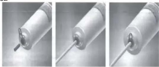
WATER FILTER REPLACEMENT (IF APPLICABLE)
6) Insert water supply tube into the inlet side of the fi until the tube stops.
It is suggested to change the water filter every 6 months ensure the best possible water quality. Filters may be purchased at Encompass Parts (https://encompass.com/) under the SKU Z320380. After installing, check the installation thoroughly for leaks.
1) Shut off water supply.
2) Remove clips from each end of the old water filter.
3) Press down on collar at one end of the filter and tube out of the filter.
4) Repeat Step 3 on the other end of the filter.
5) Note the Flow direction on the filter.
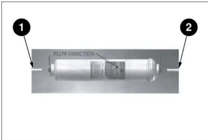
Fig. 41
1) Water supply inlet
2) Filtered water
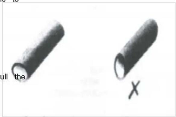
Fig. 42

NOTE
You must also ensure that the cut is square and not at any sort of angle as this could cause a leak.
7) Repeat Step 6 on the outlet side of the filter.
8) After inserting tube, re-install the clip between the cc and the filter, making sure it is secure. The clip will secure the tube to the filter.
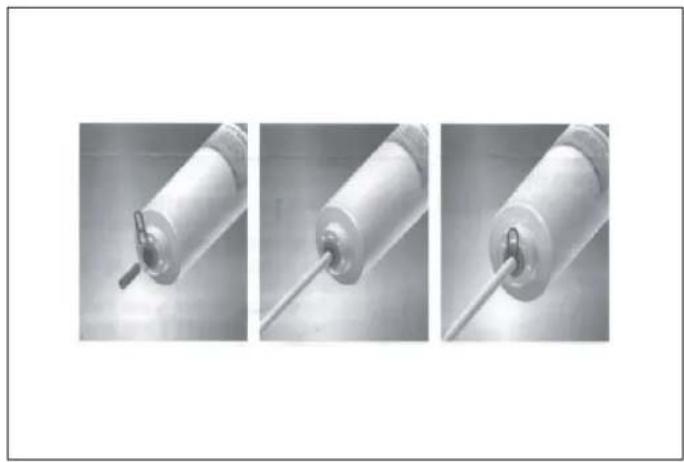
natural_image
Three sequential images showing a cylindrical device with a pointed tip, connected by a rod (no text or symbols visible)Fig. 43
9) Turn on the water and check for leaks. If leaks occur repeat Step 1 through 8. If leaks persist, discontinue and call your supporting dealer.
10) Flush filter for 5 minutes before use.

NOTE
The warranty does not cover any parts, labor, or damage to property caused by improper installation, use, maintenance, repair or service.
WAYS TO SAVE ENERGY
- Thawing frozen foods in the fridge compartment both saves energy and preserves the quality of the foods.

WARNING
Connecting your refrigerator to an energy saving system is dangerous, as this may damage your appliance.

- Do not leave the doors of your refrigerator open for a long time.
- Do not put hot food or drinks into your refrigerator.
- Do not overload the refrigerator. Cooling capacity will fall when air circulation in the refrigerator is obstructed.
- Do not place the refrigerator in direct sunlight. Install (product at least 12" (30 cm) away from heat sources such as hobs, ovens, heater units and stoves and at least 2" (5 cm) away from electric ovens.
NOTE
The temperature in the room where your refrigerator is located should at least be 50^ F ( 10^ C). Operating your refrigerator in cooler conditions is not recommended, in terms of its efficiency.
NOTE
The inside of your refrigerator must be ke perfectly clean.
- Be sure to store your food in closed containers in refrigerator.
- You can remove the drawer shelf in the freezer. Make sure that the food does not touch the tempera compartment in order to fill the freezer compartment with sensor in the fresh food compartment. To allow the the maximum amount of food. The appliance's provided food compartment to maintain its ideal storage energy consumption value has been determined with temperature, the sensor must not be obstructed by for freezer compartment shelf or drawer removed and with items. the refrigerator filled with the maximum amount of food. There is no harm in choosing to use a shelf or drawer based on the shapes and sizes of the food to be frozen. Do not place hot foods or beverages inside the appliance.
RECOMMENDATIONS FOR THE FRESH FOOD side the COMPARTMENT
FREEZING FRESH FOOD
- Wrap foods or place them in a covered container putting them in the refrigerator.
- Hot foods and beverages must have cooled down room temperature before you put them in the refrigerator.
- The food that you want to freeze must be fresh good condition.
- Divide the food into portions according to your fat daily or meal-based consumption needs.
- Pack the foods in an airtight manner to prevent from drying out, even if they are only going to for a short time.
- Materials to be used for packaging must be tear-and resistant to cold, humidity, odour, oils and a they must also be airtight. Moreover, they must be sealed and made from easy-to-use materials that is suitable for deep freezers.
-
Frozen food must be used immediately after thaw, must never be refrozen.
-
Do not freeze very large amounts of food at one tir. The quality of the food is best preserved when it is beforeen right through to the core as quickly as possib
- Placing warm food into the freezer compartment cause to the cooling system to run continuously until the food frozen solid.
RECOMMENDATIONS FOR STORING and in FROZEN FOOD
nily'Frozen foods you purchase must be stored in the conditions and at the temperature determined by the food manufacturer.
be stored ensure that the high quality achieved by the frozen food manufacturer and the food retailer is maintained, heed the following recommendations:
ids; 1) Put packages in the freezer as quickly as possible, e well after purchase.
2) Make sure that packages are labelled and dated.
ng; Check whether or not the "Use By" or "Best Before date on the packaging has passed.
ARRANGING THE FOODS
COMPARTMENT FOOD
| Freezer compartment shelves | Various frozen foods (meat, fish, ice cream, vegetables, etc.) |
| Egg tray | Eggs |
| Fridge compartment shelves | Food in pans, covered plates and closed containers |
| Door bins in the fridge compartment | Small and packaged foods or beverages (milk, fruit juice beer, etc.) |
| Crisper | Fruit and vegetables |
| Fresco compartment | Delicatessen products (cheese, butter, salami, etc.) |
| FREEZER FRIDGE NOTES | |||
| -18°C (0°F) | 4°C (39°F) | This is the recommended normal setting. | |
| -20°C (-4°F) 3°C (37°F) | These settings are recommended when the ambient temperature is above 30°C (86°F). | ||
| Super Freeze 4°C (39°F) | Use when you wish to freeze your food in a short Your appliance will return to its previous mode when the process is over. | ||
| -24°C (-11°F) 2°C (35°F) | Use these settings if you think that your fridge compartment is not cold enough because of hot ambient conditions or frequent opening and closing of the door. | ||
| -18°C (0°F) or colder | Super Cool | Use this function when you are putting a lot of things into the fridge compartment at once or when you need to cool your food quickly. It is recommended that you activate the Super Cool function 4-8 hours before adding the food. | |
Recommended Operating Temperature:
Fridge: 4°C (39°F), Freezer: -18°C (0°F).
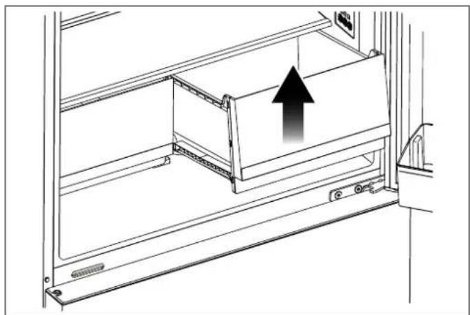
DOOR BINS
To remove a door bin, hold it from the bottom, lift it and slide it out. Please see the figure.

natural_image
Line drawing of a rectangular container with an upward arrow, no text or symbols presentFig. 44
GLASS SHELVES
REFRIGERATOR DRAWERS
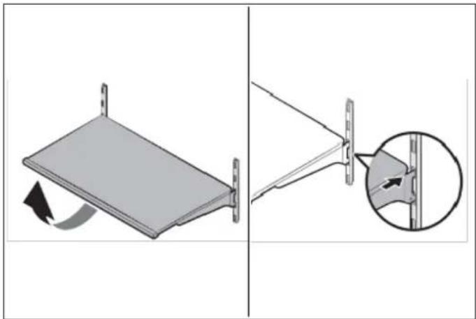
The height of the glass shelves can be adjusted manually remove a drawer
using the rear hangers. Holding a shelf from the bottom, lift
the front part and raise it to an angled position; the tabs on Pull out the drawer until it stops.
the hangers will be released and the glass shelf will move up the front section of the drawer, then up and down.
To remove a shelf
To install a drawer
- Hold the front of the shelf, then gently lift up and insert it the drawer by tilting it slightly and slowly push out.
To reinsert
- Hold the shelf at an angle so that the front is the back, then insert the top hook into the top you wish to use.
• Lower the front gently.

NOTE
To prevent breakage or scratching the interior of the fridge, use care when handling glass shelves.
natural_image
Diagram showing a mechanical assembly with a rotating component and a close-up of a pin detail (no text or symbols)Fig. 45
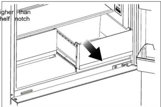
Fig. 46

natural_image
Technical line drawing of a mechanical assembly with an upward arrow indicating motion (no text or symbols present)Fig. 47

WARNING
Glass shelves must be unloaded before moving.

WARNING
You must wait for the glass shelves to reach room temperature before immersing them in water for cleaning.

WARNING
The door may not close if the door bins are positioned at the same level as the glass shelves. After placing the shelves, make sure that the door can close properly. The drawers preserve the humidity of your vegetables, allowing you to store them for a longer time without h to keep them in their bags.

NOTE
Never leave vegetables in their plastic bags in the drawer. If they are left in their pla bags, they will spoil in a short period of time.
If you prefer that the vegetables not come into contact with automatic ICE MAKER (DEPENDING ON each other for hygienic reasons, you can use perforated MODEL)
paper, foam or other similar materials instead of plastic bags.
When positioning the vegetables in the drawers, their specific weights should be taken into consideration. H and hard vegetables must be placed at the bottom of drawer and light and soft vegetables must be kept on
Pears, kiwis, tomatoes, cucumbers, apricots, peaches, broccoli, lettuce, cabbage, parsley and spinach are fruits and vegetables that emit ethylene gas. Do not place them in the same crisper with other fruits and vegetables. The ethylene gas emitted by these foods causes other fruits and vegetables to ripen sooner and to spoil in a shorter span of time.
Do not remove the drawer from the refrigerator unless you must do so.
Fig. 49
BOTTLE HOLDER

natural_image
Diagram of two bottles on a tray with directional arrows indicating flow or movement (no text or symbols)Fig. 48
- When the ice maker dumps ice into the ice box, ar sounds are part of normal operation.
If ice is not dispensed for a long period of time, it clump in the Ice box. If this occurs, please remove ice and empty the box.
In case of prolonged absence and the ice maker is used, close the water valve to prevent leaks.
It is recommended that the first several ice charges be discarded to ensure highest quality of Ice. Do not store cans or containers that will burst when frozen.

CAUTION
Do not allow your children to touch the id maker. This could cause injury.

Fig. 50
The bottle holder can be used to fix the bottles. You can place it on the small or lower door rack and slide to left or right as you prefer.
- It is advisable to put the tall bottles or glass bottles in rack with bottle holder.
The service life of the product will be extended and frequently encountered problems will occur less often product is cleaned periodically.

WARNING
Switch off the product before cleaning.
Never use gasoline, benzene or any similar substance cleaning purposes.
Never use any sharp or abrasive instrument, soap, household cleaner, detergent or wax polish for cleaning
Dissolve one teaspoon of sodium bicarbonate in half of water. Soak a cloth in the solution and wring it thoroughly. Wipe the interior of the refrigerator with cloth and dry thoroughly.
Make sure that no water penetrates the lamp housing other electrical parts.
If you will not be using the refrigerator for a long time,
unplug it, remove all of the food from inside, clean leave the door ajar.
Check regularly that the door seals are clean. If not, them.
Take everything out of the appliance before removing door and the upper fridge shelves.
Remove the door bins by pulling them up. Slide the downwards to reinstall them after cleaning.
Never use water or cleaning agents that contain chloro clean the exterior surfaces or the chrome parts of the product. Chlorine causes abrasion on metal surfaces type.
PREVENTING UNPLEASANT ODOURS
Materials that can cause odours are not used in the manufacturing of our refrigerators. However, odours ma
be emitted by foods that are stored improperly or if interior surfaces of the product are not cleaned as
Please heed the following tips in order to prevent this problem:
It is important that the refrigerator be kept clean. residues, spills, etc. can cause odours. For this reclean your refrigerator with a solution of sodium bicarbonate dissolved in water every 15 days. Never detergents or soaps.
- Keep your food in closed containers. Microorganism escaping from uncovered containers can cause unpleasant odours.
- Never keep expired or spoiled foods in your refrigerator.
PROTECTING PLASTIC SURFACES
if the
Do not put unsealed containers containing oils in liquid or meals cooked in oil into your refrigerator, as these damage the plastic surfaces of your refrigerator.
If oil is spilled or smeared onto the plastic surfaces, c and rinse the affected areas immediately using warm wa
CLEANING THE INTERIOR SURFACES
To clean the interior surfaces and all removable parts, them with a mild solution of dishwasher soap, water, a sodium bicarbonate. Rinse and dry thoroughly.
a liter
Do not allow the water to come into contact with the equipment or control panel.

WARNING
Do not use vinegar, rubbing alcohol or an alcohol-based cleaning agent on any of the interior surfaces.
it out and Although this appliance automatically defrosts, a layer of frost may occur on the freezer compartment's interior was if the freezer door is opened frequently or kept open to clean. long.
If the frost is too thick, choose a time when the freeze nearly empty and proceed as follow:
1) Remove existing food and accessories baskets, unplug the appliance from the mains power and leave the d shelves open.
Ventilate the room thoroughly to accelerate the process of the time to 2) When defrosting is completed, clean your freezer as described above.
STAINLESS STEEL EXTERIOR SURFACES
Use a non-abrasive stainless-steel cleaning agent; apply with a soft, lint-free cloth.
For polishing, wipe the surface gently with a damp mic fibre cloth and follow with dry wash leather.
Always rub in the direction of the grain of the stainless steel.
FOLANING THE DOOR SEALS
Take care to keep door seals clean. Sticky food and can cause seals to stick to the cabinet and tear when open the door. Wash the seals with a mild detergent
Swarm water. Rinse and dry them thoroughly after cleani
erator.

NOTE
Please review this list before calling customer service. This will save you time and money. This list contains frequently encountered problems that are not the result of faulty workmanship or wear. You product may not have some of the features described here.
NOISE FROM THE APPLIANCE
The sounds below are quite normal
Compressor running noises.
Air movement noise form the small fan motor in the freezer compartment or other compartments.
Gurgling sound similar to water boiling.
- Popping noise during automatic defrosting.
Clicking noise before the compressors starts.
Clicking noise when you get the water.
The motor running noises when you get ice.

WARNING
Don't try to repair the appliance yourself. the problem persists after you have made the checks mentioned below, contact a qualified electrician, authorized service technician or the shop where you purchased the product.
Other unusual noises are due to the reasons below and may need you to check and take action:
• The cabinet is not level.
The back of appliance touches the wall.
Bottles or containers have fallen or are rolling.
ower
APPLIANCE IS NOT WORKING CORRECTLY
- Check whether the power cord is plugged into the outlet properly.
- Check the fuse or circuit of your power supply, replace if
necessary.
- It is normal that the freezer is not operating during ^16
defrost cycle, or for a short time after the appliance
switched on to protect the compressor.
THE MOTOR RUNS CONTINUOUSLY
It is normal to frequently hear the sound of the motor. need to run more when in following circumstances: g the
ce Temperature setting is set colder than necessary.
OUDOURS FROM THE COMPARTMENTS
• The interior may need to be cleaned.
• Some food, containers or wrapping cause odours.
- Large quantity of warm food has recently been stored within the appliance.
The temperature outside the appliance is too high. - Doors are kept open too long or too often.
• After your installing the appliance or it has been switched off for a long time.
A LAYER OF FROST OCCURS IN THE COMPARTMENT
Check that the air outlets are not blocked by food and ensure food is placed within the appliance to allow sufficient ventilation. Ensure the door can be fully closed. To remove the frost, please refer to the cleaning and chapter.
TEMPERATURE INSIDE IS TOO WARM
You may have left the doors open too long or too frequently;
- Or the doors are kept open by some obstacle;
- Or the appliance is located with insufficient clearance the sides, back and top.
TEMPERATURE INSIDE IS TOO COLD
Increase the temperature by following the "Display controls" chapter.
DOORS CAN'T BE CLOSED EASILY
Check whether the top of the refrigerator is tilted back by 0.1"-0.2" (2.5-5 mm) to allow the doors to self-close. or if something inside is preventing the doors from closing.
THE LIGHT IS NOT WORKING
The LED light may be damaged. Refer to replace Li lights in cleaning and care chapter.
The central system has disabled the lights due to the door being kept open too long, close and reopen the door to reactivate the lights.
HEAR WATER BUBBLING IN THE REFRIGERATOR
This is normal. The bubbling comes from the refrigerant coolant liquid circulating through the refrigerator.
For any warranty information and service request, contact us:

In USA: https://us.bertazzoni.com/more/support
In CANADA: https://ca.bertazzoni.com/more/support
DU BUREAU DE NOTRE PRÉSIDENT
DIMENSIONS DU PRODUIT 48
EXIGENCES ÉLECTRIQUES 49
EXIGENCES DE PLOMBERIE (SELON LE MODÈLE) 49
PREMIÈRE UTILISATION 55
OUTILS ÉVENTUELLEMENT REQUIS 56
MISE À NIVEAU DE L'APPAREIL 57
INVERSEMENT DE LA PORTE 58
INSTRUCTIONS DE CONFIGURATION DU PANNEAU D'AFFICHAGE 63
natural_image
Diagram showing a lightning bolt striking down inside a refrigerator with an electrical plug attached (no text or symbols)Fig. 1
DIMENSIONS DU PRODUIT
VUE DU DESSUS
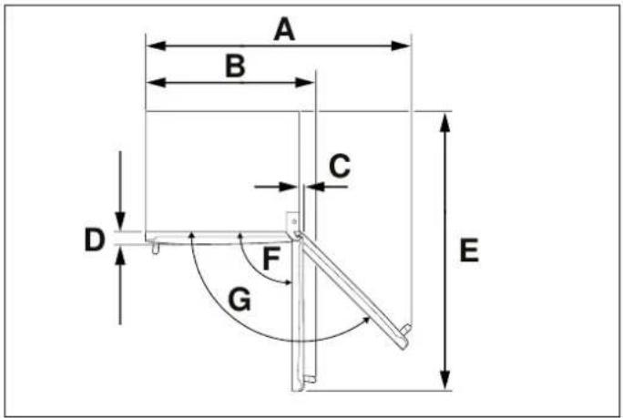
Fig. 3
A. 52" 1/2 (1333)
E. 56" 5/8 (1439)
B. 34" 9/16 (878)
F. 90^
C. 1" 1/32 (26)
G. 130^
D. 3" (76)
VUE AVANT

Fig. 4
A. 31" 1/4 (794)
B. min. 65" 1/2 (1664) - max. 66" 5/8 (1692)
C. 40" 5/16 (1024)
D. 7/16" (11)
E. 25" 13/16 (656)
VUE LATÉRALE

Fig. 5
A. 29" 3/4 (756)
B. 27" 1/2 (698)
C. 24" 1/2 (610)
D. 1 / 2'' (13)
E. 1" 1/8 (28)

NOTE
Fig. 15
Fig. 21
INVERSEMENT DE LA PORTE
Fig. 23

Fig. 24
Fig. 22

ATTENTION !
natural_image
Pure technical diagram showing a mechanical assembly with an upward arrow, no text or symbols presentFig. 25

flowchart
graph TD
    A["Device"] --> B["Component 9"]
    A --> C["Component 10"]
    A --> D["Component 6"]
    A --> E["Component 7"]
    A --> F["Component 8"]
Fig. 27
Fig. 26
natural_image
Technical line drawing of a mechanical bracket assembly (no text or symbols)Fig. 28
natural_image
Diagram of a refrigerator with an open door and an upward arrow indicating direction (no text or symbols)Fig. 29
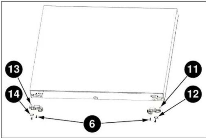
Fig. 30
natural_image
Technical diagram of a door frame with arrows indicating movement or force direction (no text or symbols present)Fig. 32
Fig. 33
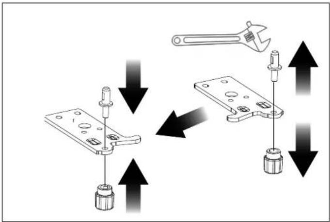
Fig. 34
natural_image
Diagram of a refrigerator with an open door and a downward arrow indicating a loading or status (no text or symbols present)Fig. 35

natural_image
Technical line drawing of a mechanical bracket assembly (no text or symbols)Fig. 36
Fig. 37
natural_image
Technical line drawing of a mechanical assembly with a downward arrow indicating a component (no text or symbols present)Fig. 38
filtre
retirez
natural_image
Three sequential images showing a cylindrical mechanical component with a pointed tip, connected by a rod (no text or symbols visible)Fig. 41
Fig. 43
natural_image
Two cylindrical objects with a cross mark labeled 'X' on the right (no other text or symbols)Fig. 42
MOYENS D'ÉCONOMISER L'ÉNERGIE

MISE EN GARDE
natural_image
Line drawing of a rectangular container with an upward arrow indicating direction (no text or symbols)Fig. 44
ÉTAGÈRES EN VERRE

MISE EN GARDE
natural_image
Diagram showing a folding panel with rotation and a close-up of the structure (no text or symbols)Fig. 45

MISE EN GARDE
natural_image
Technical line drawing of a mechanical cabinet or rack with an arrow indicating direction (no text or symbols present)Fig. 46

natural_image
Technical line drawing of a mechanical assembly with an upward arrow indicating motion (no text or symbols present)Fig. 47
natural_image
Diagram of two bottles on a conveyor belt with directional arrows indicating flow or movement (no text or symbols)Fig. 48
natural_image
Technical line drawing of a mechanical assembly with a rotating component (no text or symbols)Fig. 49
natural_image
Technical line drawing of a mechanical assembly with a hand operating a tool (no text or symbols present)Fig. 50
Au Canada: https://ca.bertazzoni.com/more/support
natural_image
Diagram showing a lightning bolt striking down an electrical plug into a grid-patterned enclosure (no text or symbols)Fig. 1
DIMENSIONES DEL PRODUCTO
VISTA SUPERIOR

Fig. 3
A. 52" 1/2 (1333)
E. 56" 5/8 (1439)
B. 34" 9/16 (878)
F. 90^
C. 1" 1/32 (26)
G. 130^
D. 3" (76)
VISTA FRONTAL
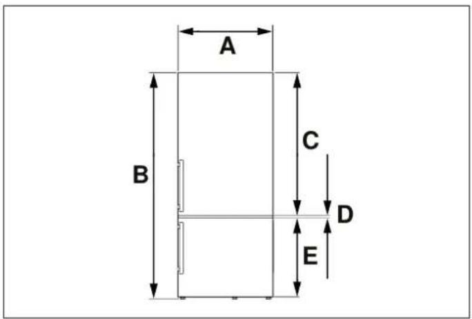
Fig. 4
A. 31" 1/4 (794)
B. min. 65" 1/2 (1664) - máx. 66" 5/8 (1692)
C. 40" 5/16 (1024)
D. 7/16" (11)
E. 25" 13/16 (656)
VISTA LATERAL

Fig. 5
A. 29" 3/4 (756)
B. 27" 1/2 (698)
C. 24" 1/2 (610)
D. 1 / 2'' (13)
E. 1" 1/8 (28)

NOTA
flowchart
graph TD
    f --> g
    g --> h
    h --> i
Fig. 7
flowchart
graph TD
    A --> E
    B --> E
    C --> D
    D --> F
    E --> G
    F --> H
Fig. 13
Fig. 15
Fig. 21
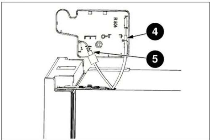
Fig. 24
Fig. 22

ATENCIÓN
natural_image
Diagram of a mechanical clamp or bracket assembly with an upward arrow indicating force or direction (no text or symbols present)Fig. 25

flowchart
graph TD
    A[" "] --> B[" "]
    B --> C[" "]
    C --> D["7"]
    C --> E["8"]
    F["9"] --> G["10"]
    G --> H[" "]
    H --> I[" "]
    I --> J["6"]
    J --> K[" "]
    K --> L[" "]
    style A fill:#f9f,stroke:#333
    style B fill:#ccf,stroke:#333
    style C fill:#cfc,stroke:#333
    style D fill:#fcc,stroke:#333
    style E fill:#cff,stroke:#333
    style F fill:#ffc,stroke:#333
    style G fill:#cfc,stroke:#333
    style H fill:#fcc,stroke:#333
    style I fill:#cfc,stroke:#333
    style J fill:#fcc,stroke:#333
    style K fill:#cfc,stroke:#333
    style L fill:#fcc,stroke:#333
Fig. 27
Fig. 26
natural_image
Technical line drawing of a mechanical bracket assembly (no text or symbols)Fig. 28

flowchart
graph TD
    A[" "] --> B[" "]
    B --> C[" "]
    C --> D[" "]
    D --> E["12"]
    D --> F["11"]
    D --> G["6"]
    G --> H[" "]
    H --> I[" "]
    I --> J["13"]
    I --> K["14"]
Fig. 30

natural_image
Diagram of a refrigerator with an open door and upward arrow indicating storage or ventilation (no text or symbols)Fig. 29
natural_image
Technical diagram of a door frame with arrows indicating movement or force direction (no text or symbols present)Fig. 32
Fig. 33

Fig. 34
natural_image
Diagram of a computer tower with an open door and a downward arrow indicating loading or download (no text or symbols present)Fig. 35
natural_image
Line drawing of an open refrigerator with a downward arrow indicating the interior pan, labeled 'Fresh Zone' (no other text or symbols)Fig. 37
natural_image
Technical line drawing of a mechanical bracket assembly (no text or symbols)Fig. 36
natural_image
Technical line drawing of a mechanical assembly with a component and directional arrow (no text or symbols)Fig. 38
Fig. 41
natural_image
Three sequential images showing a cylindrical device with a pointed tip, connected by a rod (no text or symbols visible)
NOTA
natural_image
Simple line drawing of a rectangular container with an upward arrow inside, no text or symbols presentFig. 44
ESTANTES DE VIDRIO
natural_image
Diagram showing a mechanical assembly with a rotating component and a close-up of a bracket detail (no text or symbols)Fig. 45
natural_image
Technical line drawing of a mechanical assembly with an upward arrow indicating motion (no text or symbols present)Fig. 47

ADVERTENCIA
natural_image
Diagram of two bottles on a conveyor belt with directional arrows indicating flow or movement (no text or symbols)Fig. 48
En Canadá: https://ca.bertazzoni.com/more/support
www.bertazzoni.com
Via Palazzina, 8.
42016 Guastalla RE
- FROM THE DESK OF OUR PRESIDENT
- This manual will help you to get started using your GENERAL SAFETY appliance quickly and in a safe manner.
- WARNING
- NOTE
- INTENDED USE
- CHILDREN'S SAFETY
- CAUTION
- PACKAGING INFORMATION
- HYDROCARBON (HC) WARNING
- Risk of Fire or Explosion:
- PRODUCT DIMENSIONS
- ELECTRICAL REQUIREMENTS
- PLUMBING REQUIREMENTS (DEPENDING ON MODEL)
- CONNECTING THE WATER SUPPLY
- CONNECTING THE WATER SUPPLY TO FILTER INLET
- CONNECTING THE WATER FILTER OUTLET TO REFRIGERATOR
- FIXING THE WATER FILTER
- NOT PROVIDED ADDITIONAL PARTS (IN THE PLASTIC BAG)
- LEVELING THE APPLIANCE
- REVERSING THE DOOR
- SWITCHING CELSIUS AND FAHRENHEIT
- FRIDGE TEMPERATURE CONTROL
- SUPER COOL
- SUPER FREEZE
- DOOR OPEN ALARM
- ICE CONTROL (DEPENDING ON MODEL)
- DEMO MODE
- ECO
- WATER FILTER REPLACEMENT (IF APPLICABLE)
- WAYS TO SAVE ENERGY
- RECOMMENDATIONS FOR THE FRESH FOOD side the COMPARTMENT
- FREEZING FRESH FOOD
- RECOMMENDATIONS FOR STORING and in FROZEN FOOD
- ARRANGING THE FOODS
- DOOR BINS
- GLASS SHELVES
- REFRIGERATOR DRAWERS
- To remove a shelf
- To install a drawer
- To reinsert
- PREVENTING UNPLEASANT ODOURS
- PROTECTING PLASTIC SURFACES
- CLEANING THE INTERIOR SURFACES
- STAINLESS STEEL EXTERIOR SURFACES
- FOLANING THE DOOR SEALS
- NOISE FROM THE APPLIANCE
- APPLIANCE IS NOT WORKING CORRECTLY
- THE MOTOR RUNS CONTINUOUSLY
- OUDOURS FROM THE COMPARTMENTS
- A LAYER OF FROST OCCURS IN THE COMPARTMENT
- TEMPERATURE INSIDE IS TOO WARM
- TEMPERATURE INSIDE IS TOO COLD
- DOORS CAN'T BE CLOSED EASILY
- THE LIGHT IS NOT WORKING
- HEAR WATER BUBBLING IN THE REFRIGERATOR
- DU BUREAU DE NOTRE PRÉSIDENT
- DIMENSIONS DU PRODUIT
- INVERSEMENT DE LA PORTE
- ATTENTION !
- MOYENS D'ÉCONOMISER L'ÉNERGIE
- MISE EN GARDE
- ÉTAGÈRES EN VERRE
- DIMENSIONES DEL PRODUCTO
- NOTA
- ATENCIÓN
- ESTANTES DE VIDRIO
- ADVERTENCIA
Brand : BERTAZZONI
Model : REF31BMFIXNV
Category : Refrigerator