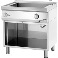
286302 - Electric bain-marie BARTSCHER - Free user manual and instructions
Find the device manual for free 286302 BARTSCHER in PDF.


| Product type | Electric bain-marie 1 module on cabinet |
| Brand | Bartscher |
| Model | 286302 |
| Dimensions (W x D x H) | 800 x 700 x 845 mm |
| Power | 2.0 kW |
| Voltage / Frequency | 230 V / 50 Hz |
| Cable type | H07 RN-F 3x1 mm² |
| Water connection | UNI-ISO 7/1 R 1/2 |
| Max water pressure | 3 bar |
| Temperature range | 30 °C to 90 °C |
| Main material | Stainless steel (chrome-nickel 18-10) |
| Mounting type | On cabinet (floor version) |
| Feet adjustment | Yes, adjustable height |
| Filling | Via filling tap |
| Drainage | Via front tap |
| Working thermostat | Adjustable with bulb in the tank |
| Safety thermostat | Fixed to the bottom of the tank |
| Heating elements | Adhesive to the bottom of the tank |
| Maintenance | Clean with warm water and neutral detergent; no high-pressure jet |
| Compliance | EEC directives 2006/95, 2004/108, 98/37/EC |
| Country of use | France and other countries with local standards |
Frequently Asked Questions - 286302 BARTSCHER
User questions about 286302 BARTSCHER
0 question about this device. Answer the ones you know or ask your own.
Ask a new question about this device
Download the instructions for your Electric bain-marie in PDF format for free! Find your manual 286302 - BARTSCHER and take your electronic device back in hand. On this page are published all the documents necessary for the use of your device. 286302 by BARTSCHER.
USER MANUAL 286302 BARTSCHER
BAGNOMARIA ELETTRICI BAINS-MARIE ÉLECTRIQUES ELECTRIC BAIN MARIES ELEKTRO-BAIN-MARIE ELEKTRISCHE BAIN-MARIE BEMARY ELEKTRYCZNE
SERIE 70
288.301
286.301
288.302
286.302
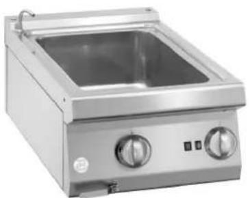
natural_image
Exterior view of a stainless steel kitchen appliance with dual control knobs and a square sink (no visible text or symbols)288.301
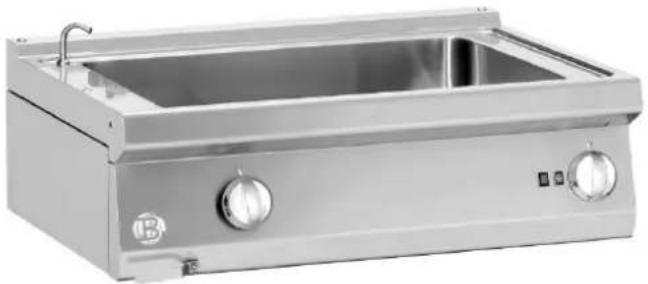
natural_image
Exterior view of a stainless steel laboratory appliance with control knobs and a rectangular interior (no visible text or symbols)288.302
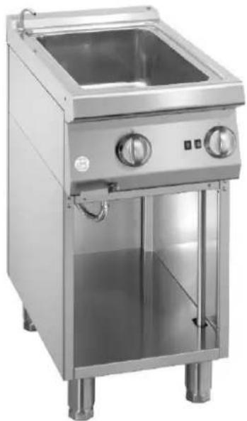
natural_image
Exterior view of a stainless steel commercial kitchen appliance with dual doors and control knobs (no visible text or symbols)286.301
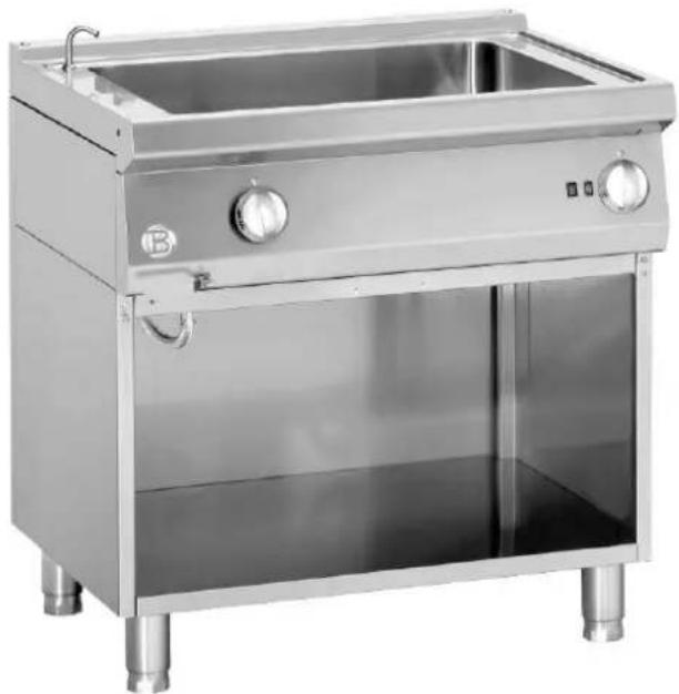
natural_image
Exterior view of a stainless steel kitchen appliance with control knobs and a side panel (no visible text or symbols)286.302
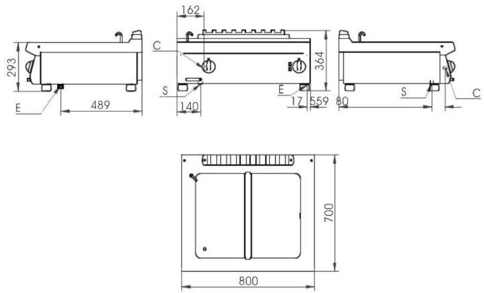
(E= elettrico \ électrique \ electric\ Elektrisch \ eléctrico; C= Carico acqua \ Remplissage d'eau \ Water filling \ Wasser anfüllen; S= Scarico acqua \ Évacuer l'eau \ Water emptying \ Wasser entleeren)
288301 288302
Fig. - Abb. 1: Dimensioni \ Dimensions \ Floor space dimensions \ Raumbedarfsmasse
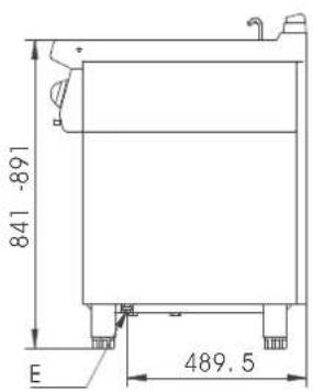
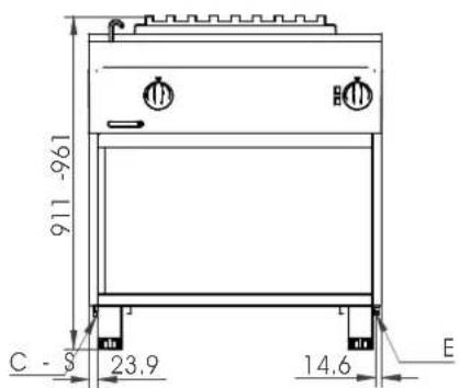
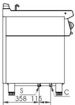
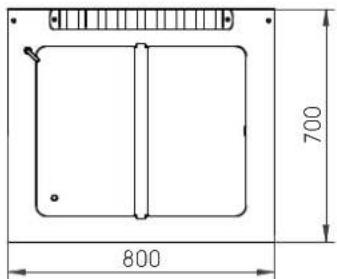
(E= elettrico \ électrique \ electric\ Elektrisch; C= Carico acqua \ Remplissage d'eau \ Water filling \ Wasser anfüllen; S= Scarico acqua \ Évacuer l'eau \ Water emptying \ Wasser entleeren)
286301
286302
Fig. - Abb. 2: Dimensioni \ Dimensions \ Floor space dimensions \ Raumbedarfsmasse \ Espacio máximo necesario
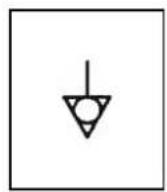
Fig. – Abb. 3: Simbolo
equipotenziale \ Symbole
equipotenziel \ Equipotenziale label \ Äquipotenzial Symbol
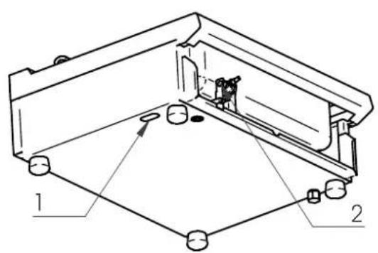
Fig. - Abb. 4: Allacciamento alla rete idrica (versione top) Raccordement à l'alimentation d'eau Water supply connection Anschluss an die Wasserversorgung.
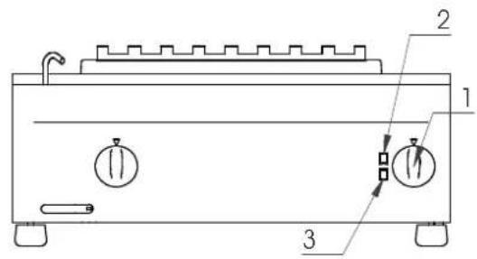
Fig. - Abb. 5: Istruzioni uso\ Instructions d'utilisation\ Instruction for use\ Bedienungsanleitungen
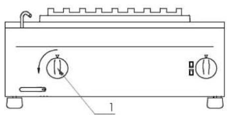
Fig. - Abb. 6: Carico vasca\ Remplissage du bainmarie\ Vat Filling\ Anfüllen des Beckens
natural_image
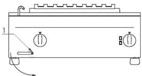
Technical line drawing of a portable appliance with control buttons and a scroll, no text or symbols presentFig. - Abb. 7: Scarico vasca\ Vidage du bain-marie\ Vat Draining \ Entleeren des Beckens
natural_image
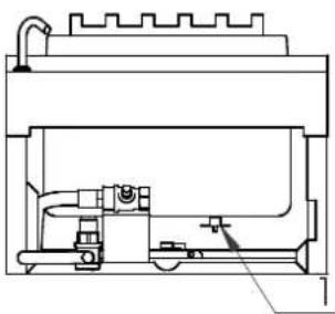
Cross-sectional diagram of a mechanical device with internal components and no visible text or symbolsFig. – Abb. 8 : Sostituzione del termostato in sicurezza\ Changement de Thermostat de sécurité\ Sobstituting the safety thermostat\ Austausch von Sicherheitsthermostat
BAGNOMARIA ELETTRICI SERIE 70
288.301
286.301
288.302
286.302
INSTALLAZIONE, USO
E MANUTENZIONE
(Tabella 1) CARATTERISTICHE TECNICHE
| Modello | Descrizione | Dimensioni LxPxH [mm] | Pot. Elet. (E) [Kw] | Tensione (F) [V] | Freq. (G) [Hz] | Cavo Tipo H07 RN-F [mm2] | Pressione aliment. acqua MAX [bar] | Racc. acqua |
| 288301 | Bagnomaria elettrico 1/2 moduloTop | 400x700x295 | 1.0 | 230 | 50 | 3x1 | 3 | UNI-ISO 7/1 R 1⁄2 |
| 288302 | Bagnomaria elettrico 1 moduloTop | 800x700x295 | 2.0 | 230 | 50 | 3x1 | 3 | UNI-ISO 7/1 R 1⁄2 |
| 286301 | Bagnomaria elettrico 1/2 modulo su Mobile | 400x700x845 | 1.0 | 230 | 50 | 3x1 | 3 | UNI-ISO 7/1 R 1⁄2 |
| 286302 | Bagnomaria elettrico 1 modulo su Mobile | 800x700x845 | 2.0 | 230 | 50 | 3x1 | 3 | UNI-ISO 7/1 R 1⁄2 |
AVVERTENZE
Generali
INSTALLATION, UTILISATION
ET ENTRETIEN
CONDITIONS D'INSTALLATION
Lieu d'installation
INSTALLATION, USE AND MAINTENANCE
(Table 1) TECHNICAL FEATURES
| Model Description | Dimensions LxDxH [mm] | Elect. Power. (E) [Kw] | Tension (F) [V] | Freq. (G) [Hz] | Cable Type H07 RN-F [mm2] | Water Supply Pressure MAX [bar] | Water Connector | |
| 288301 | Electric bain maries 1/2 unit Top | 400x700x295 | 1.0 | 230 | 50 | 3x1 | 3 | UNI-ISO 7/1 R 12 |
| 288302 | Electric bain maries 1 unit Top | 800x700x295 | 2.0 | 230 | 50 | 3x1 | 3 | UNI-ISO 7/1 R 12 |
| 286301 | Electric bain maries 1/2 unit on Cabinet | 400x700x845 | 1.0 | 230 | 50 | 3x1 | 3 | UNI-ISO 7/1 R 12 |
| 286302 | Electric bain maries 1 unit on Cabinet | 800x700x845 | 2.0 | 230 | 50 | 3x1 | 3 | UNI-ISO 7/1 R 12 |
WARNINGS
General
- Read the instructions carefully before installation, use and maintenance of the appliance.
- Installation must be carried out by qualified personnel following the manufacturer's instructions in the specific manual.
- The appliance must only be used by trained personnel and only for the intended use.
- In the event of breakdown or malfunctioning, switch off the appliance and call in after sales assistance only from an authorised centre.
- Use only original spare parts; otherwise no liability is accepted by the manufacturer.
- The appliance must not be washed with high pressure water sprays, neither must the openings or air fumes on heat inlets/outlets be blocked.
ATTENTION! The manufacturer declines any liability for damage caused by wrong installation, tampering, making unauthorised changes, improper use, poor maintenance, installation of non-original spare parts, not observing local norms, incorrect use or not observing the instructions in this booklet
For the installer
- The functioning of the appliance must be explained and shown to the user. After having ensured that everything is clear, the instruction booklet must be handed over.
TECHNICAL FEATURES
The following instructions for set up and functioning refer to electric appliances. The data plate with all the information to refer to regarding the appliance, is situated inside the right or left side of the control panel, depending on the model.
The appliances have been checked in accordance with the European directives below.
CEE 2006/95 - Low Tension (LVD)
CEE 2004/108 - Electromagnetic Compatibility (EMC)
98/37/CE - Appliance to the directives
and the particular reference norms.
Declaration of compliance
The manufacturer declares that the appliances of their production are compliant with the above mentioned EEC directives and requires that installation be done observing the norms in force.
DESCRIPTION OF APPLIANCES
Bain maries
A sturdy structure in steel placed on four feet which make it possible to regulate the height in the version with cabinet. The external coating is in Chrome-Nickel 18-10 stainless steel.
The vat is made entirely of stainless steel. It is heated by an electric heater activated by a thermostat. This thermostat makes it possible to regulate the temperature in a range from 30^ C to 90^ C.
Neutral cabinet
In the standing versions, doors are available for closing the compartment to create a neutral cabinet. There are also racks available for inserting GASTRONORM wash bowls.
PROVISIONS FOR INSTALLATION
Place
It is advisable to install the appliance in a well-ventilated room or under an extractor hood. The appliance may be installed as a single unit or together with others.
Installation
Installation operations, voltage conversions to other than the original, starting up the installation or appliance, ventilation and maintenance must be done following the manufacturer's instructions and observing the norms in force, by qualified personnel, in compliance with the following provisions (GB):
■ Health and Safety at Work Act, 1974
■ Codes of Practice, BS6173, 1982
■ The Building Regulations, 1985
■ The Building Standards Regulations, 1981
For others countries follow the relevant local rules for:
■ Building regulations and local fire prevention provisions
■ Safety norms in force
■ The Electrical Norms in force
■ The Fire Brigade rules
INSTALLATION
Preliminary operations
Remove the appliance from the packaging, ascertaining that it is intact and, if in doubt, do not use it but call in professionally qualified personnel. After having verified that the appliance is in good condition, the protective film may be removed. Carefully clean the external parts of the appliance with warm water and detergent using a cloth to remove all remaining residues and then dry it with a soft cloth. If there are still traces of glue residues, remove them by using a suitable solvent (e.g. acetone. For no reason use abrasive substances. After having been put into place, the appliance must be levelled by regulating the adjustable feet.
Electric connection
Before connecting the appliance, it is necessary to check that the voltage of the power supply available corresponds to the voltage the appliance has been set for. In the event that they do not correspond, it is necessary to modify the connection as shown in the electric diagram, if voltage change is provided for. . The terminal block is situated on the base and can be reached removing the screws that fix the support to the block. For an easier connection it is recommended to remove the panel, too. Furthermore, the efficiency of the earth connection must be checked, and also that the earth conductor on the connecting side is longer than the other conductors, and that the connecting cable has a wire bunch adequate for the power absorbed by the appliance and is at least type H05 RN-F. As in international provisions, before installing the appliance a unipolar device must be installed with a contact opening of at least 3mm which must not interrupt the YELLOW-GREEN earth wire. The device must be installed near the appliance, it must be approved and have adequate capacity for the absorption of the appliance (see technical features).
The appliance must be connected to the EQUIPOTENTIAL system. The connector is situated near the end of the electric cable and is identified by a label with the symbol shown on fig. 3 (page 4)
ATTENTION! All the parts, protected and sealed by manufacturer may not be regulated by the installer if not specifically indicated.
Water supply connection
Connect the water inlet piping to the distribution system following the provisions in force.
For the version “top” it is necessary to make the connection directly on the water filling tap (fig. 4 – page 4). For this operation it is necessary to remove the handles, the lever of the draining tap and the board. Pass the pipe through the slot (1) placed on the left bottom of the bain-marie and connect it to the water filling valve (2). Use a flexible pipe that for rule has to resist to a temperature of 90^ C at least.
INSTRUCTIONS FOR USE
Vat Filling (fig. 6 - pag. 4)
First of all ensure that the drain tap is tightly closed, having done this turn the water load knob anticlockwise (1), fill the vat to the marked level.
Bain maries (fig. 5 - pag. 4)
To heat a bain maries vat, proceed in the following way:
- Turn the thermostat knob (1) to the position of the required heating temperature;
- Push the button (2). Inside of it a green lamp remains always lighted to indicate the presence of the tension. At the same time the warning lamp lights (3): the orange lamp turns off when the temperature in the tank is reached.
- For switching off, push the button (2).
Vat Draining (fig. 7 - pag. 4)
To drain the vat it is necessary to turn the lever on the control panel (1) anticlockwise. At the time of draining, make sure that the appliance is not working.
ATTENTION! Only use the appliance under surveillance. Never heat up an empty vat.
Abnormal functioning
If for any reason, the appliance does not start or stops working during use, check that the energy supply and the control knobs are set correctly; if all is regular, call customer service.
CARE AND MAINTENANCE OF THE APPLIANCE
Cleaning
ATTENTION! Before doing any cleaning, make sure that the appliance is disconnected from the electric mains. During cleaning operations, avoid using direct or high pressure sprays of water on the appliance. Cleaning must be done when the appliance is cold.
The parts in steel can be cleaned with warm water and neutral detergent, using a cloth; the detergent must be suitable for cleaning stainless steel and must not contain abrasive or corrosive substances. Do not use common steel wool or anything similar which, depositing iron particles, could cause rust from it. It is also better to avoid using sandpaper or emery paper. Only in the event of encrusted dirt, pumice stone in powder may be used but an abrasive synthetic sponge or stainless steel wool would be preferable, to be used in the direction of the grain. After washing, dry with a soft cloth.
If the appliance is out of use for a long time, it is advisable to disconnect the main electricity supply and wipe all stainless steel surfaces with a cloth soaked in vaseline oil in order to give it a protective film and air the rooms now and again.
Maintenance
ATTENTION! Before doing any kind of maintenance or repairs, make sure that the appliance is disconnected from the electric mains.
The following maintenance operations must be carried out at least once a year by specialised personnel. It is advisable to have a maintenance contract.
- Check for correct functioning of all control and safety devices;
- Check the condition of the power cable;
SUBSTITUTING COMPONENTS
ATTENTION! Before carrying out any substitutions, make sure that the appliance is disconnected from the electric mains.
Working thermostat
For the replacement it is necessary to remove the handles, the lever of the draining tap and the board. The working thermostat consists of a commanding unit connected to the temperature selector on the back of the board and of a bulb placed on the side of the vat of the bain-marie. Remove and replace the part
Safety thermostat (fig.8 - pag. 5)
For the replacement of the part it is necessary to remove the handles, the lever of the draining tap and the board. The safety thermostat (1) is fixed at the bottom of the tank of the bain-marie through a screw. Remove and replace the part.
Heating elements
It is necessary to remove the handles, the lever of the draining tap and the board. Disconnect the wiring. The heating elements of the bain-marie consist of adhesive sheets glued on the bottom of the vat. For their replacement it is necessary to remove the part of the bain-marie to which the tank is welded. Unscrew the screws that fix the surface at the base of the top. Remove and replace the part. It is recommended to remove the residual glue through special products for the cleaning of glues, clean and wait that the eventually present chemical components have been evaporated, then place the heating element taking care that it is fixed very well in the bottom of the tank. Replace the surface and verify that the electrical connections are correctly placed.
WHEN SUBSTITUTING, ONLY ORIGINAL SPARE PARTS SUPPLIED BY THE MANUFACTURER MUST BE USED. THE OPERATION MUST BE CARRIED OUT BY AUTHORIZED PERSONNEL.
THE MANUFACTURER RESERVES THE RIGHT TO WITHOUT NOTICE MODIFY THE FEATURES OF THE APPLIANCES DESCRIBED IN THIS MANUAL.
ELEKTRO-BAIN-MARIE SERIE 70
288.301
286.301
288.302
286.302
natural_image
Technical line drawing of a mechanical assembly with labeled components (no text or symbols present)natural_image
Technical line drawing of a portable kitchen appliance with control buttons and a handle (no text or symbols)natural_image
Cross-sectional diagram of a mechanical device with internal components and no visible text or symbolsnatural_image
Line drawing of a portable kitchen appliance with control knobs and a handle (no text or symbols)natural_image
Cross-sectional diagram of a mechanical device with internal components and no visible text or symbols- BAGNOMARIA ELETTRICI BAINS-MARIE ÉLECTRIQUES ELECTRIC BAIN MARIES ELEKTRO-BAIN-MARIE ELEKTRISCHE BAIN-MARIE BEMARY ELEKTRYCZNE
- BAGNOMARIA ELETTRICI SERIE 70
- AVVERTENZE
- Generali
- CONDITIONS D'INSTALLATION
- Lieu d'installation
- WARNINGS
- General
- For the installer
- TECHNICAL FEATURES
- Declaration of compliance
- DESCRIPTION OF APPLIANCES
- Bain maries
- Neutral cabinet
- PROVISIONS FOR INSTALLATION
- Place
- Installation
- Preliminary operations
- Electric connection
- Water supply connection
- INSTRUCTIONS FOR USE
- Vat Filling (fig. 6 - pag. 4)
- Bain maries (fig. 5 - pag. 4)
- Vat Draining (fig. 7 - pag. 4)
- Abnormal functioning
- CARE AND MAINTENANCE OF THE APPLIANCE
- Cleaning
- Maintenance
- SUBSTITUTING COMPONENTS
- Working thermostat
- Safety thermostat (fig.8 - pag. 5)
- Heating elements
- WHEN SUBSTITUTING, ONLY ORIGINAL SPARE PARTS SUPPLIED BY THE MANUFACTURER MUST BE USED. THE OPERATION MUST BE CARRIED OUT BY AUTHORIZED PERSONNEL.
- ELEKTRO-BAIN-MARIE SERIE 70
Brand : BARTSCHER
Model : 286302
Category : Electric bain-marie