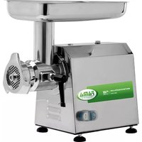
410122 - Chopper Fama - Free user manual and instructions
Find the device manual for free 410122 Fama in PDF.


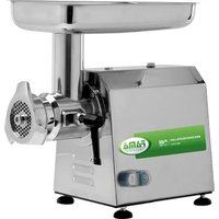
| Product type | Professional meat grinder |
| Brand | Fama |
| Model | 410122 (compatible with TS12, TI12, TS22, TI22, etc.) |
| Dimensions (L x W x H) | 370 x 220 x 440 mm (TS12 model) |
| Weight | 19 kg (TS12 model) |
| Power supply | 230V single phase, 50Hz (or 400V three-phase depending on model) |
| Motor power | 0.75 kW / 1 HP (TS12 model) |
| Hourly output | 150 to 200 kg/h (TS12 model) |
| Grinding mouth diameter | 70 mm (TS12 model) |
| Food contact materials | 18/8 stainless steel, AISI 304, food-grade cast iron, alumina |
| Noise level | Less than 70 dBA |
| Protection rating | IP X3 |
| Max ambient temperature | +40 °C |
| Warranty | 12 months |
| Safety | Emergency stop, thermal protection, safety device on hopper (TI 32R model) |
| Maintenance | Clean after each use, disassemble, do not use chlorine or steam cleaner |
| Main functions | Grind fresh non-frozen meat, make stew meat, Swiss steaks, patties, and sausages |
Frequently Asked Questions - 410122 Fama
User questions about 410122 Fama
0 question about this device. Answer the ones you know or ask your own.
Ask a new question about this device
Download the instructions for your Chopper in PDF format for free! Find your manual 410122 - Fama and take your electronic device back in hand. On this page are published all the documents necessary for the use of your device. 410122 by Fama.
USER MANUAL 410122 Fama
OPERATING MANUAL
INDEX
CHAP. 1. CONTENT ORGANIZATION AND CONSULTATION MODALITY 3
CHAP. 2. GENERAL INFORMATION AND CHARACTERISTICS 4
CHAP. 3. SAFETY INSTRUCTIONS 8
CHAP. 4. TRANSPORTATION, PUT ON SERVICE AND USE 9
CHAP. 5. MAINTENANCE, BREAKS RESEARCH AND CLEANING 14
CHAP. 6. SELLING 17
CHAP. 7. MANUFACTURING MATERIALS 17
CHAP. 8. OPTIONAL 18
GUARANTEE
The machine is guaranteed 12 (twelve) months from the sale date.
The guarantee covers the machines reparations acquired c/o the authorized sale points, if it is demonstrated that they are faulty in the materials or in the assembly, to the conditions here follow described:
- For guarantee gets on the free change of all parts that are resulted manufacturing defect. The guarantee decades if not coupled from fiscal ticket or invoice certifying the purchase and for the following cases:
a. Machine tampering or damaging due to negligence;
b. Machine use with non conformance modalities to the warnings described in the instructions handbook;
c. Damages caused from the non environment suitability in which the device works and from phenomenon not dependent from the machine normal functioning (voltage values irregularities and frequency in the net plant);
d. Reparations interventions performed from people or centers not authorized from the manufacturer,
-
The intervention request in guarantee will have to be performed only in the sale points or authorized laboratories;
-
The machine will have to be free port returned to the manufacturer for the reparation and the transportation expenses are always charged to the receiver,
- It is excluded the machine change nor the guarantee prolongation following the intervention for damage;
- The manufacturer doesn't answer for direct or indirect damages of any nature to people or things for the improper use of the machine or for lacked use during the time occurring for the reparations.
MODEL TS 12 / TI 12 / TS 22 / TI 22 / TSK 12 / TIK 12 / TSK 22 / TIK 22 / TS 32 ECO / TI 32 ECO / TI 12R / TI 22R / TI 22RS / TI 32R / TI32RS
Use Instructions Manual
Issue January 2018
CHAP. 1. CONTENT ORGANIZATION AND CONSULTATION MODALITY
MANUAL PURPOSE
MANUAL IMPORTANCE
The present instruction manual for the use is to be considered as integral part of the machine:
- Must be kept for all the machine life.
- Must be coupled with the machine in case of its ceasing.
- Besides to show all useful notices for the operators, contains (collected in specific chapters) the electric diagrams that will be used for the possible maintenance interventions and reparation.
SCOPE / MANUAL PURPOSE
The instructions manual for the use has the purpose to furnish to the commitment all necessary information so that, except of an adequate supplied machine use, is able to manage the same in the more autonomous way and possibly safe.
Besides the present manual has been written with the purpose to supply indications and warnings to know the supplied machine, to understand its principles and functioning limits. For possible doubts you can call the Authorized Assistance Center.
RECEIVERS
The present instruction manual for the use, delivered in number of 1 copy together with the machine, is supplied as integral part of the machine, is turned both to the operators both to the skilled technicians qualified to the installation, use and maintenance.
The prevention and protection service responsible of the commitment and the additional employees, to whom is assigned the machine, must take vision of the present instructions manual for the use, with the aim to adopt all technical and organizational measures
RESPONSIBILITY

If the present manual endures damages or is lost, it is possible to request a copy to the Authorized Assistance Center.
The present manual reflects the technical state during the machine manufacturing; the manufacturer reserves the right to update the production and of consequence other manual issues, without the obligation to update productions or previous manuals, if not in particular cases regarding the health and the people safety.
Pay particularly attention to the residual risks content present on the machine and the prescriptions to which the operators must keep.
The manufacturer is the responsible for the machine in its original configuration.
The manufacturer isn't the responsible for damages caused from the improper use or not correct of the machine and documentation or for damages caused from the imperative standards violation, negligence, lack of experience, imprudence and the not respect of regulation standards on behalf of the employer, of the operator or the maintenance man and for every possible damage, caused from an irrational, improper and/or wrong use.
The manufacturer isn't the responsible for the consequences caused from the not original spare parts use or of equal characteristics.
The manufacturer is the responsible only for the information showed in the manual original version in Italian language.
The prescriptions non-fulfillment contained in this manual will cause the guarantee immediate decay.
The factory responsibilities, that supervision to the working activities, in the field of the foreseen respective attributions and competence, must:
➢ Carry out the foreseen safety measures;
Make informed the operators about the specific risks whom are exposed and bring to their knowledge the prevention essential standards;
➢ Prepare and require that the single operators observe the safety standards and use the protection means put at their disposal:
➢ Work an operator, contemporary, on this product.
SIMBOLOGY MEANING
Here follow it is clearly specified the symbols and definitions meaning, which will be used in the present document.


DANGER
Show the danger presence for who works on the machine and for who is in the vicinity, so the indicated activity must be performed in accordance with the actual accident prevention standards and with the indications showed in the present manual

PRECAUTION
Show a warning on useful information and/or further recommendations and/or shrewdness about the actual operation.

ATTENTION
Show an operation to perform with attention to avoid damage to the machine.
CHAP. 2. GENERAL INFORMATION AND CHARACTERISTICS
USE DESTINATION AND MANUFACTURE PARTS
Meat mincer designed to be used with plate holes diameter smaller or equal to 8mm.
The mincer – grater, here follow is called “machine”, è designed to mince, reduce of size fresh meat not frozen, through cutting tools to obtain meat sauce, hamburgers, meatballs and sausages. The meat must be without bones, or other parts of different consistency from the meat.
With the grater group placed on the opposite side of the machine, to grater tough cheese, bread and biscuits.
The machine is constituted from an electric motor inserted in a unique merger (basic machine body). In some versions the merger can be recovered from a bonnet (hulled machine body).
The meat to grind, is loaded manually in the load hopper, placed in the superior zone of the machine and always manually and with the pestle help is introduced in the grinding neck towards the Archimedean screw.
The hopper is blocked to the machine neck. The pestle is of plastic material suitable for the contact with food products.
The grinding group is of different typologies: Enterprise it comes with 6mm plate holes diameter, Half Unger, Total Unger.
The plate in turn is pressed against the cutter from the wheel inserted on the grinding group mouth.
The grinding group is dismanticable, all direct contact materials with the food material are in conformance with the actual hygienic standards for food.
In accordance with the functioning requirements and production, the machine can be constituted with different optional parts.
The machine is supplied with the identification plate on which the following data are showed:
| CE X X Y | ||
| Mod. | Hp | |
| Nr. | kW | |
| 1N PE AC. 230V 50Hz | A | |
| Kg. | 2011 | kA |
[fac simile]
TECHNICAL AND MANUFACTURING DATA
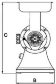
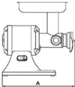
| TECHNICAL DATA | MODEL | ||||
| TS12 | TS22 | TSK12 | TSK22 | TS32ECO | |
| Motor power (kW) /(Hp) | 0.75/ 1 1.1/ 1,5 | 0.75/ 1 1.1/ 1,5 1,5/2 | |||
| Grinding mouth internal size (mm) | 70 82 70 82 | 98 | |||
| Timetable production (kg/h) | 150/ 200 300 150/ 200 300 400 | ||||
| Mass (kg) | 19 22 21 23 | 31 | |||
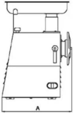
| Maximum sizes: A x B x C (mm) | 370x220x440 | 440x240x510 | 440x220x440 | 490x240x500 | 500x240x510 |
  | |||||
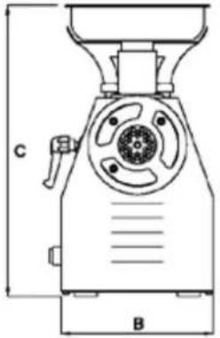
| TECHNICAL DATA | MODEL | |||||||||
| T1 12 | T1 22 | TIK 12 | TIK 22 | TI32 ECO | T1 12R | T1 22R | T1 22RS | T1 32RS | T1 32R | |
| Motor power (kW) /(Hp) | 0.75/1 | 1.1/1,5 | 0.75/1 | 1.1/1,5 | 1,5/2 | 1,1/1,5 | 1,5/2 | 1,5/2 | 1,6/2,2 | 2,2/3 |
| Grinding mouth internal size (mm) | 70 | 82 | 70 | 82 | 98 | 70 | 82 | 82 | 98 | 98 |
| Timetable production (kg/h) | 150/200 | 300 | 150/200 | 300 | 400 | 250 | 350/400 | 400/450 | 500 | 600 |
| Mass (kg) | 19 | 22 | 23 | 25 | 35 | 26 | 31 | 35 | 40 | 50 |
| Maximum sizes: A x B x C (mm) | 430x215x440 | 440x215x440 | 480x215x430 | 490x215x430 | 500x225x510 | 400x260x490 | 450x260x530 | 435x260x525 | 510x260x525 | 475x300x560 |
  | ||||||||||
| Continue acoustic power level considered equal to A | Minor of 70dBA | |||||||||||||||
| Current nature – Frequency | Macchine plate | |||||||||||||||
| Full charge current | Macchine plate | |||||||||||||||
| Use nominal voltage | Macchine plate | |||||||||||||||
| Auxiliary circuits voltage | AC 24V – DC 24V | |||||||||||||||
| Mass and neutral | TT e TN | |||||||||||||||
| Protection degree | IP X3 | |||||||||||||||
| Use place | Inside | |||||||||||||||
| Machine positioning | Working ground used in the food field of height included between 900/1100mm from the trampling level of adequate capacity, with a free circulation space of at least 800mm | |||||||||||||||
| Environment air max temperature | +40°C | |||||||||||||||
| Requested minimum illumination | 500 lux | |||||||||||||||
| Product directive conformance | 2006/42/CE, 2006/95/CE and successive modifications and integration, Reg. 1935/2004 | |||||||||||||||
| GROUP | MODEL | |||||||||||||||
| TS12 | TI12 | TS22 | TI22 | TSK12 | TIK12 | TSK22 | TIK22 | TS32ECO | TI32ECO | TI12R | TI22R | TI22RS | TI32RS | TI32R | ||
| Basic machine body | ● | ● | ● | ● | ● | |||||||||||
| Hulled machine body (I) | ● | ● | ● | ● | ● | ● | ● | ● | ||||||||
| Grinding group Enterprise | ● | ● | ● | ● | ● | ● | ● | ● | ● | ● | ● | ● | ● | ● | ● | ● |
| Grinding group half Unger | ● | ● | ● | ● | ● | ● | ||||||||||
| Grinding group total Unger | ● | ● | ● | ● | ● | |||||||||||
| Grinding group Enterprise (Uniko) | ● | ● | ● | ● | ● | ● | ||||||||||
| Optional tomato masher | ● | ● | ● | ● | ● | ● | ||||||||||
| Optional puree masher | ● | ● | ● | ● | ● | ● | ||||||||||
| GROUP | EXAMPLE | |
| 1. Loading hopper2. Machine body3. Control switch ON / OFF4. Mouth block knob5. Blockage wheel6. Machine | 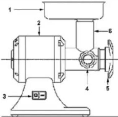 Basic machine body Basic machine body | 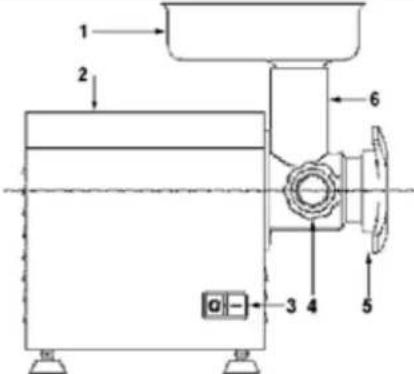 hulled machine body (I) hulled machine body (I) |
| Grinding group Enterprise1.Grinding mouth2. Archimedean screw3. Cutting knife4. Drilled plate5. Blockage wheel | 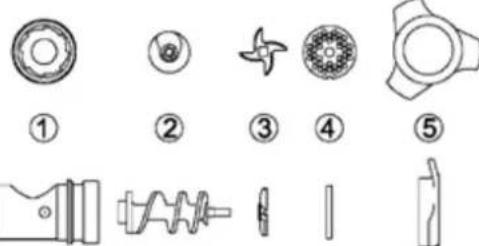 | |
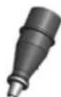
| Grinding group half Unger1.Grinding mouth2. Archimedean screw3. First Drilled plate4. Cutting knife5. Second Drilled plate6. Ring7. Blockage wheel | 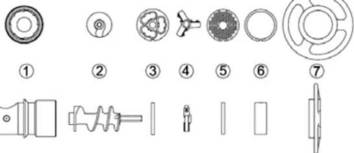 | |
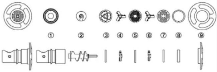
| Grinding group total Unger1.Grinding mouth2. Archimedean screw3. First Drilled plate4. First cutting knife5. Second Drilled plate6. First cutting knife7. Third Drilled plate8. Ring9. Blockage wheel |  1 1  | [9] 2 3 4 5 6 7 8 9 |
| Grinding group Enterprise (Uniko)1. Grinding mouth2. Archimedean screw3. Cutting knife4. Drilled plate5. Blockage wheel | 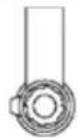 1 1 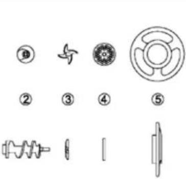 | |
NORMAL USE, IMPROPER USE, NOT CORRECT USE OR FORBIDDEN
The machine described in the present instructions manual for the use is foreseen to be driven from an only operator skilled and prepared on residual risks, but with the competence, in safety matter, of maintenance employees.

In its NORMAL USE, and reasonably foreseeable, the machine can be used only to mince, reduce of size fresh meat not frozen or not surgelata, through cutting tools The meat must be without bones or other parts of consistency different from the meat.

The machine must not be used IN IMPROPER WAY; in particular:
- It must not be used for domestic uses,
- It must not functioned with parameters different from those showed in the technical characteristics table,
- For every use of the machine with modalities different from those showed in the present manual, the manufacturer declines every responsibility,
- The user is responsible of the damages resulting from the lacked exercise conditions observance in accordance with the greed technical specifications and order confirmation,
- don't let function the vacuum machine,
- Not tamper or damage intentionally nor remove or hide the labels.

The machine must not be used IN NOT CORRECT WAY or FORBIDDEN so some damages or injuries could be caused for the operator; in particular:
- It is forbidden to move the machine when it is connected to the electric feeding;
- It is forbidden to draw the electric feeding cable or the machine to disconnect the feeding plug,
- It is forbidden to put weights on the machine or on the electric feeding cable,
- It is forbidden to put the electric feeding cable on sharp parts or with burn danger,
-
It is forbidden the machine use with the damaged and not integer electric feeding cable or with the control devices;
-
It is forbidden to leave the machine off with the electric feeding cable connected with the feeding plug,
-
It is forbidden to leave the loaded machine unguarded;
-
It is forbidden to insert any type of object inside the motor ventilation cap;
-
It is forbidden to put the machine above different objects from the working ground used in the food field of height included between 900 - 1100mm from the trampling level,
-
It is forbidden insert every type of object under the machine base or place clothes or other things between the machine support pressure feet and the working ground,
-
It is forbidden the use of inflammable substances, corrosive or harmful for the cleaning.
-
It is forbidden to plunge the machine in water or in other liquids;
-
It is forbidden the not authorized personnel use and with clothes different from that showed for the use,
-
It is forbidden to introduce in the grinding neck and in the grater mouth, products or objects having characteristics different from those showed in the normal use, such as for example bones, frozen meat, not food products, or other objects as scarves, etc...,
-
It is forbidden to remove the hopper during the machine working or however when the food product has been left to work,
-
It is forbidden to slacken the mouth block knob or the blockage wheel both during the working and however before of 5 sec from the machine stop control,
- It is forbidden the functioning with the protection shelters and fixes not blocked correctly or removed;
- It is forbidden the partial removal of the protections and of the danger signals.
- It is forbidden the functioning without that all the precautions about the residual risks elimination have been adopted on behalf of the user,
- It is forbidden to smoke or use free flame devices and manipulate incandescent materials, unless some suitable safety measures aren't adopted,
- It is forbidden to work or regulate the control and blockage devices as knobs or similar both during the machine functioning, both if you aren't authorized
- the use of plates with holes diameter bigger than 8mm is forbidden.

The user is however responsible of the damages resulting from the lacked observance of the specified normal use conditions. For possible doubts you can enquire at the Authorized Assistance Center.
CHAP. 3. SAFETY INSTRUCTIONS
INTRODUCTION

The lacked standards and safety procedures applications can be danger and damage sources. The machine means bound in the use for the respect, on behalf of the final user, of:
- all rules, of insertion in the environment and of people behavior, fixed from the laws and/or applicable standards; with particular reference to the fixed plant upstream of the supplied machine and for its connection / functioning;
- All further instructions and use warnings making part of the technical / graphic documentation annexed to the same machine.

Except where differently specified, the personnel which performs the installation interventions, connection, maintenance, reassembly, and reuse, damages or breakdowns, demolition and dismantling must be a skilled personnel qualified in safety matter and educated on the residual risks, with the competencies, in safety matter, of the maintenance employees.
ENVIRONMENTS, WORKING AND PASSING PLACES
The work environment must answer to the directive 89/654/CEE requirements. In the working area foreign object must not be present. The employer, in the directive 89/391/CEE respect, concerning the measures realization turned to promote the safety and workers health improvement during the work, must provide to eliminate or reduce the showed residual risks as foreseen in the present manual.
WARNINGS ON THE RESIDUAL RISKS
RESIDUAL RISK DUE TO THE FIXED PROTECTIONS REMOVAL, INTERVENTIONS ON BROKEN/WORN
PARTS

For any evenience the operator must not try to open or remove a fixed protection or tamper a safe device.
In the phase of equipment, maintenance and cleaning, and during all further manual operations that happens introducing the hands or other body parts in the machine dangerous areas, a residual risk remains due above all to:
- Knocks with machine manufacturing parts,
- Grazing and/or abrasion with machine rough parts,
- Cut with tools sharpened parts.
Besides, the operator and the maintenance man must be skilled for the intervention connected to the manual operations with open protections, must be trained on the joined consequent risks and must be authorized from a responsible person.
PROTECTION DEVICES ON THE MACHINE

The machine protections and safety devices must not be removed.
If they must be removed for extraordinary maintenance requirements some measures will have to be immediately adopted ready to put in evidence and to reduce at the possible minimum limit the danger.
The putting back in its place of the protection or of the safety device must happen as soon as the reasons, that have made necessary their temporary removal, are stopped.

The machine transmission parts are completely isolated by means of fixed protections which don't allow the access for none kinematical chain.
Taking into account of the machine use modality and its use destination, the moving elements aren't isolated from fixed protections, moving protections or other safety devices.
The grinding group parts result placed at some distances from the access points such for which some dangerous points aren't reachable.
For all safety functions including the control and check systems parts joined to the safety, some well-tested components and safety principles have been used.
CHAP. 4. TRANSPORTATION, PUT ON SERVICE AND USE

The machine management is allowed only to the authorized personnel and opportunely educated and endowed of a sufficient technical experience.
Before to switch on the machine perform the following operations:
Read with attention the technical documentation,
➢ Know what protections and emergency devices are available on the machine, their location and functioning.
The not authorized use of commercial parts and accessories making part of the protections and safety devices can cause some malfunctions and the ranger situation beginning for the operators.
The operator must besides have received an adequate training.
WORKING POSITIONS AND OPERATORS TASKS
As described in the instructions manual for the use, the machine is designed to be driven from an operator skilled and informed on the residual risks, but with the competences, in safety matter, of the maintenance employees.
The normal working zone of the operator is:
- The machine lateral zone near the hopper (defined loading zone) in normal conditions of functioning for the food product manual loading operations in the hopper and during the pestle use to direct the food product inside the machine neck, with the fixed protections in closed and blocked position;
- The machine anterior zone near the food product unloading zone in normal conditions functioning for the food product manual drawing operations stored in a proper container, with the fixed protections in closed and blocked position
TRANSPORTATION, HANDLING AND STORING
All transportation and handling operations must be performed from informed and trained personnel and must have read and understood the safety prescriptions showed in the present instructions manual for the use. Occur:

- Perform the machine handling and transportation always when you find it uncharged;
- Verify that the lifting means are able to support the loading weight and overall dimensions in safety conditions and that are approved and subjected to a regular maintenance,
- Adopt all necessary measures to assure the means and loads maximum stability in relation to their masses and barycentre,
- Avoid to make suffer to the machine rude shaker or accidental collisions during the moving and the loading,
- Perform the handling with continue movements, without pulls or repeated impulses.
PACKING REMOVAL – OPENING MODALITY
PACKING DECRIPION - HOW GET RID OF THE PACKING MATERIAL
The machines are packaged so that the seepage / liquids insight, organic matters or alive beings is avoided: it is represented from a covering in polyethylene around the machine, and all inserted in a cardboard box of adequate size. The empty spaces within the box are occupied from the fill material.
Don't waste the packaging in the environment, but restore it for possible transportations or to address it to the recycling agencies.
The evaluation and the management with the aims of the biological compatibility of the products used in the packaging, are of the user competence and responsibility.
It is an employer obligation to be acquainted of the actual laws in own country and work so that to observe these legislations.
It is forbidden and besides liable to fines, leave the machine and the electric equipment in the environment.
PREPARATION PRELIMINARY OPERATIONS
STABILITY
The machine stability is designed so that, in the foreseen functioning conditions, taking into account of the climatic conditions, is such as to allow the use without reversal risk, fall, or inopportune movement.
Taking into account of the conformation and its position, the machine results to be intrinsically steady without fastening needs to the working ground.
ELECTRIC FEEDING
The electric feeding connection must be in conformance with the country legislation in which is used.
The electric feeding so must be maintained in conformance with the following technical prescriptions:
- The electric feeding must be always of type and have an intensity corresponding to the specifications indicated in the machine plate. If excessive voltages are applied, some components will be damaged irreparably,
- A differential device must be foreseen coordinated with the protection circuit, respecting the legislation, the legislative and regulated disposals in force in the installation country;
- The electric feeding cable outside the machine cover must be made pass in the spaces prepared from You and adequately protected;
- If present the neutral conductor (N) before feeding the electric equipment, as for You its continuity must be guaranteed (connected and available).
- Before to feed the electric equipment, as for You must be guaranteed the continuity of the green yellow conductor of the protection equipotential circuit.
ELECTRIC FEEDING SECTIONING DEVICE
The feeding sectioning device, as comparable from what described in the power circuits diagram delivered with the electric equipment, is supplied for the machine feeding unique source.
In case of incompatibility between the net socket and the device plug change the socket with another type suitable from maintenance personnel.
The feeding sectioning device allows to separate (insulate) the machine electric equipment from the feeding, with the aim to make possible the interventions performing without electric shocks risks.
The sectioning device presents two possible positions:
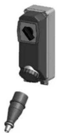
OFF o "disconnected", the electric equipment results sectioned from the electric feeding
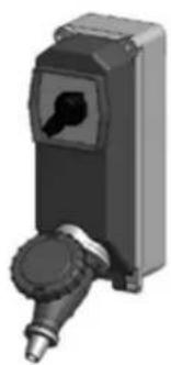
ON o “connected”, the electric equipment results connected to the electric feeding
GRINDING GROUP ASSEMBLY / DISASSEMBLY

The assembly / disassembly operations of any machine part are performed with the stop machine and with the plug disconnected from the socket, or with the sectioning device in OFF.
The grinding groups that can be foreseen, in accordance with the working requirements, can be: Enterprise, half Unger and total Unger.
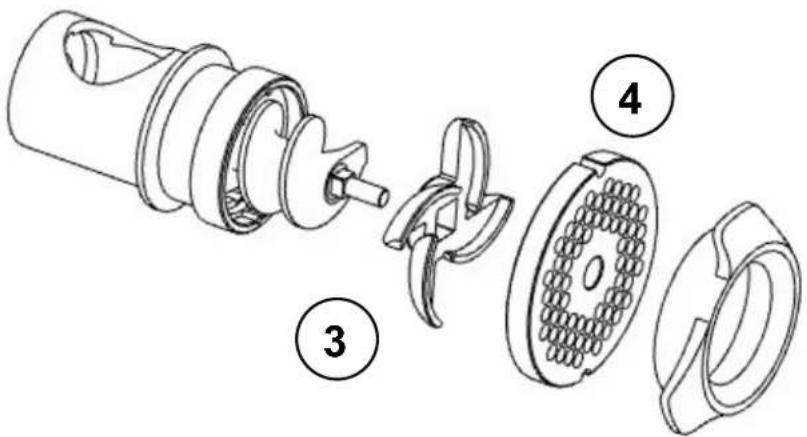
The grinding group Enterprise assembly on the machine takes place in two phases (in exemplifying way it is showed the mincer with basic machine.
| The phase n. 1 for thegrinding groupEnterpriseis performed on a working ground following the under reported order:1. Insert in the pipe union (1) in the order:Archimedean screw (2), cutting knife oriented as in figure and inserted in the dragging pivot (3), drilled plate (4) inserted in the pipe union place (1);2. Screw down and tighten the blockage wheel (5). | 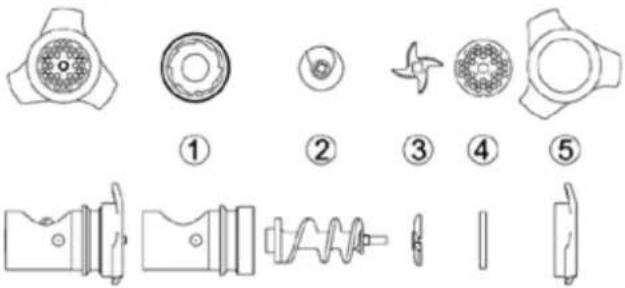 | |
 | ||
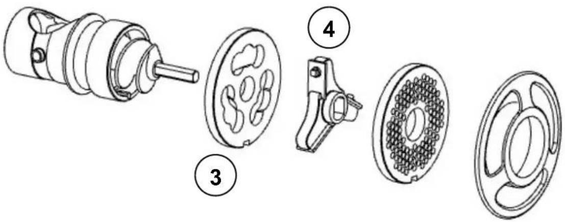
| The phase n. 1 for theHalf Unger grindinggroupis performed on a work round following the under reported order:1. Insert in the pipe union (1) in the order:Archimedean screw (2), first plate (3), cutting knife oriented as in figure and inserted in the dragging pivot (4), second drilled plate (5) inserted in the pipe union place (1), ring (6);2. Screw down and tighten the blockage wheel (7). | 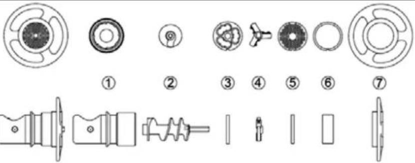 | |
 | ||
The phase n. 1 for the Total Unger grinding group is performed on a work round following the under reported order:
-
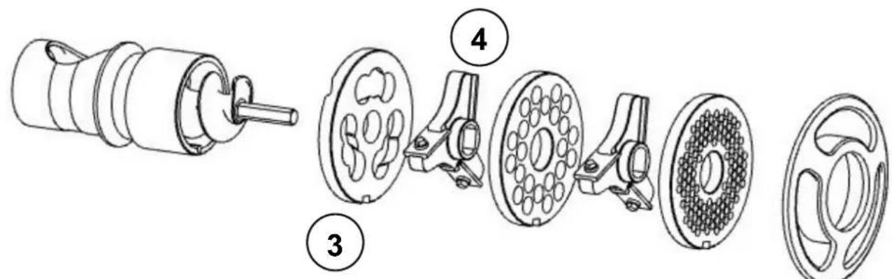
Insert in the pipe union (1) in the order: Archimedean screw (2), first plate (3), cutting knife oriented as in figure and inserted in the dragging pivot (4), second drilled plate (5) inserted in the pipe union place (6), third drilled plate (7) inserted in the pipe union place (1), ring (8);
-
Screw down and tighten the blockage wheel (9).
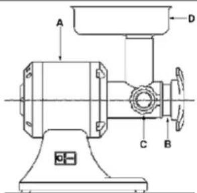
The phase 2 is performed on the machine:
- Insert up to the blow the complete grinding group (B) on the machine (A);
- Tighten the mouth stop knob (C) up to when the grinding group (B) is blocked on the machine (A);
- Insert the hopper (D) in the machine neck
- In these conditions the machine is ready to work.
The disassembly activities of the grinding group from the machine are performed following in the backwards way the assembly phases previously described, starting from the phase n. 2 passing to the phase n. 1.
For a plate and knife better improvement and duration it is advised to keep them always coupled.
GRINDING GROUP ROTATION

The operations here follow indicated must be performed from the machine maintenance manskilled personnel in the electric maintenance field of the industrial machines).
For machines fed with three phase voltage (3 PE AC 400V 50Hz), slacken lightly the blockage wheel so as don't make a strong pressure on the drilled plate as for the cutting knife. During the switching on verify that the Archimedean screw / grater roll rotates in anticlockwise sense.
If there is an clockwise rotation, switch off the machine disconnecting the plug, disassembly it, disconnect two phase conductors and invert them of position.
FUNCTIONING DESCRIPTION
The control devices are designed and manufactured so as much sure and reliable and resistant to the service normal stresses, to the foreseeable strains and to the external agents. Besides they are clearly visible, locatable and marked from a suitable marking. Here follow the main control devices are showed:
| TYPE / COLOR REFERENCE / DESCRIPTION | |
| button / black “0” / button for | the machine stop control |
| Button / white “1” / button for | the machine start control |

STARTING
The machine starting is possible only with a voluntary action on the control device foreseen for this aim: white button “T” for the machine starting control.
NB. In the TI 32R model the starting is possible only with the inserted hopper and correctly positioned.
STOP
For the stop control push the black button "0". In case of momentary or extended stop, before to get in function the machine, all food products must be removed within the machine: follow the indications relative to the grinding group disassembly.
FUNCTIONING SAFETY
If the machine is under stress, or is submitted to too long functioning times or submitted at overloaded, the same stops immediately for the thermal protection functioning. In this case wait that it is completely cooled before proceeding to the starting function. The TI 32R model has a safety device on the hopper. The incorrect positioning or the hopper lacked use involves the machine not functioning.
VOLTAGE LACKING
In case of electric feeding breaking or if the machine is disconnected from the electric net, this last one will be able to be restarted only following the starting function, after the electric feeding back or the reconnection to the electric net.
CONTROLS AND VERIFICATIONS BEFORE STARTING
| VERIFICATION / CONTROL BEFORE THE STARTING | MODALITY AND CHECKS |
| Check that:Extraneous objects aren’t on the machine, inside the hopper, inside the machine neck | Sight control of the indicated parts, to check of objects or extraneous bodies lacking as for example different tools, clothes, etc... and that there isn’t however the food product.In case of presence, provide with their removal. |
| Check the cleaning:➢ Of the machine neck internal parts and of the grinding group➢ Of the pusher➢ of the machine external surface | All indicated parts surfaces, before the machine use must be checked visually to verify their cleaning.For the sight check of the grinding group internal parts, provide with its disassembly.In case of molds presence or other type of dirtiness, provide with the cleaning procedure in accordance with the chapter 5 indications |
| Check the integrity:➢ of the fixed protections,➢ of the loading hopper,➢ of the machine neck,○ of the machine body | All fixed protections, etc., must perform the function for which have been foreseen.Indicated parts sight check to verify their integrity in their surface external part.The parts must be however changed at the first erosion signals or breaking. |
| Check the functionality:➢ of the control system parts / safety control;➢ Of the control devices. | All devices must perform the function for which have been foreseen. Control directly the devices so that these ones determine the waiting function.The actuators and all parts must be however changed to the first erosion signals or breaking. |
| Check the absence:➢ Of strange noises after the starting | During the functionality checking of the control devices, if there are strange noises, due for example to a seizing or mechanical breaks, stop immediately the machine and activate the maintenance service. |
| Check the absence:➢ Of oil trails both on the machine support ground both in the Archimedean screw | Both during the working, both at the end of every work, both in the assembly moment of the grinding group, check the oil trails absence in the indicated parts. If there are some fluid drops stop immediately the machine and activate the maintenance service. |
For any intervention type or for the parts change that are damaged, activate the maintenance service. The possible change must happen with manufacturer original products or at least of quality, safety and equivalent characteristics. For analysis contact the Authorized Assistance Center.
PUT IN FUNCTION
The machine operator can put in function the machine following in order the under reported indications:
-
Controls positive result for the preparation preliminary operations,
-
Controls positive result for the electric feeding.
-
Controls positive for the hopper inserting and positioning
-
Checks positive result for the grinding group assembly,
-
Checks positive result for the Archimedean screw correct rotation,
-
Checks positive result / verifications before starting and periodical,
-
Finalized checks positive result and verify the all safety conditions respect.
-
Plug connection in opportune current socket,
-
Place a gathering basin in the machine anterior zone in correspondence of the ground meat exit zone,
-
Put in the machine left side and start the machine acting the control device of start "I",
-
Introduce manually the food product within the machine neck and drive it towards the Archimedean screw using the pestle in equipment.
-
At the end of the food product introduction, or when from the drilled plate doesn't come out more the product, stop the machine acting the control device of stop "0".

It is recommended to make not work the machine in vain, without the food product
SWITCHING OFF
In succession, the switching off must follow what here under indicated:
-
Before the switching off wait the food product exile conclusion from the drilled plate,
-
Stop the machine acting the control device of stop "0",
-
Disconnect the machine plug from the feeding socket,
-
Perform the cleaning interventions
UNBLOCK IN CASE OF OBSTACLE
During the working, or during the Archimedean screw rotation, due to the food products introduction with not homogeneous parts, as for example bones, or other, the machine could block.
The same situation can determine after an electric feeding break, or when the machine is stopped with inside the food product.
To be able to resume normally the working, the grinding group must be disassembled, with the different differentiation: the disassembly must not happen slacking the blockage wheel, but slacking the grinding mouth block knob.
CHAP. 5. MAINTENANCE, BREAKS RESEARCH AND CLEANING
MAINTENANCE MAN REQUIREMENTS
With the term “maintenance” must not be understood only the periodical check of the machine normal functioning but also the analysis and the consequent remedy of all causes that for any matter put it out of service. It is absolutely necessary that for the maintenance, cleaning, parts change and breaks research activities performed from the user, this work is entrusted to skilled personnel, competence and authorized from the employer.
All operations of maintenance, cleaning and parts change, none excluded, must be definitely performed with the machine completely stopped and insulated from the external feeding sources.
MAINTENANCE PRESCRIPTIONS
PROTECTIONS REMOVAL AND/OR PROTECTION DEVICES
For any interventions described in the present chapter, it is necessary to remove from their position some fixed protections.
The removal can happen only from the maintenance man.
At the end of the interventions, these protections must be replaced and blocked in their original position, with the fastening systems which were foreseen before the intervention.
The maintenance responsible must disconnect completely the machine, as here follow reported, before to proceed with the removal of a fixed protection and/or with the element change.
INSULATION FROM THE EXTERNAL FEEDING SOURCES
Before to perform any operation of maintenance, cleaning and parts change, the external feeding sources must be sectioned and insulated.
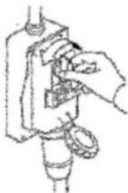
Position on "zero" the protection device placed upstream of the electric equipment feeding line.
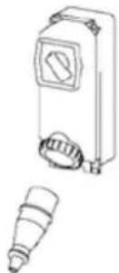
Disconnect the general sectioning device and provide to protect the plug with proper systems
BREAKS OR DAMAGES RESEARCH AND MOVING ELEMENTS UNBLOCKING
Here follow are indicate the interventions for the breaks or damages research and moving elements unblocking which can be performed from maintenance men.
| TYPE POTENTIAL CAUSE/S MODALITY AND COMPARISONS | ||
| Net voltage lacking | General Black out Contact the electric energy distributor | |
| Fuses or magneto thermals intervention place upstream of the machine feeding line | After having eliminated the causes that have determined the protection device intervention, restore it. In case of problem persistency contact an electrician technician. | |
| Functioning intervention | Protection device intervention inside the machine | Contact an electrician technician: after having eliminated the causes that have determined the protection device intervention, restore it.In case of fuses intervention, change them with types of the same model, calibration and intervention curve. |
| Cause/s not identifiable Contact directly the Authorized Assistance Center | ||
| The machine doesn’t function: the Archimedean screw doesn’t rotate | Feeding voltage lacking.Hopper not inserted or bad positioned only on model T1 32RSectioning devices set on “OFF”.Intervened fuses or not functioning magneto thermals.Lacked running button functioningThermal intervention due to the overheating | Check and restore the electric energy.Insert or reposition the hopperTurn the sectioning devies in the position “ON”Change the intervened fuses, check the magneto thermal switches state.Check the START button efficiency and eventually contact directly the Authorized Assistance Center.Wait the complete cooling before the machine restarting |
For the intervention of extraordinary maintenance, consequent to breaks or revisions or mechanical and electric damages, it is necessary an intervention request directly to the Authorized Assistance Center.
The instructions about the extraordinary maintenance don't appear in the present instruction manual for the use and so must be explicitly requested to the manufacturer.
CLEANING

It is forbidden to clean by hand the organs and the elements in motion.
All cleaning interventions must be started only and exclusively, after having unloaded the machine with the food product in working and having insulated from the electric feeding source and from external energy.
The machine, the electric equipment and the machine board components must not be ever washed utilizing water, and not in any kind of jets form and quantity; so, without "bucket" nor "rubber" nor "towel". Don't put ever directly the machine in the sink or under the tap.
The machine hygiene level classification and the associated equipment, for the foreseen use, is 2 (two): machine that, after an hygiene risk evaluation, is in conformance with applicable international standards requirements, but requests a programmed disassembly for the cleaning.
| FREQUENCY PERSONNEL MODALITY | ||
| At the end of every shift work and however before the daily use | Operator | All the surface and the machine parts destined to come in contact with the food product or with the food zones (hopper internal surface, machine neck and the grinding group, the pestle) and the jets zones (machine external surface) must be cleaned and disinfected with the under reported modalities. For the grinding group disassembly activities see the previous descriptions.➢Scrape the surfaces from the possible food product residuals (for example with plastic scrapers);➢Clean all the food zone surfaces and jets zone with soft dampened clothes (not draining) with detergent diluted in hot water (also common soap for dishes is good). Don’t soak them. With a towel clean inside the grinding mouth. Use specific products for steel,or for the aluminum: which must be liquids (not in cream or pastries however abrasive) and above all must not contain chlorine. Against the fat substances the denatured alcohol.➢Rinse with cleaned hot water and successively dry all food zone surfaces and jets zone with soft clothes that don’t lose coats.➢Only the STAINLESS steel parts of the mincer group can be washed also in dishwasher, while the aluminum ones or in cast iron showed in the following table, cannot be washed in dishwasher.➢The grinding group re assembly must happen only after a working requirement, leave the pieces wrapped in a dry soft clothes that doesn’t lose coats.DISINFECTION➢Use detergents with PH neutral not oxidizing➢If the hot water is used (>60°C) use exclusively demineralised water.➢If other products are used, these ones must be adequate to the material type.➢For the machines with aluminium parts or in cast iron (see following table) it is possible to use peracetic acid products.PERIODS OF LONG INACTIVITY➢During the machine long inactivity periods provide to pass vigorously on all steel surfaces (especially if stainless) a clothes soaked of Vaseline oil so that to spread a protective veil.THINGS NOT TO DO BEFORE OR WHILE CLEANING:➢Enter towards the moving elements without to be previously checked of their stop;➢Enter towards the moving elements without have stopped it in safety stop (blockage in zero position of the electric feeding sectioning devices)PRODUCTS NOT TO USE:➢Compressed air with jets towards the zones with flour warehouses and in general towards the machine;➢Vapor equipment;➢Detergent that contains CLORO (also if diluted) or its compounds as: the bleach, the muriatic acid, products to clear the drain, caustic soda products for the marble cleaning, in general decalcifying, etc ... can attack the steel composition, staining and oxidizing it unavoidable. The only above described products fumes can oxidize and in any case corrode the steel;➢Steel wool, brushes or abrasive discs produced with other metals or alloys (ex. Common steel, aluminum, brass, etc...) or tools that have previously cleaned other metals or alloys, that except to scratch the surface.➢Detergents in abrasive dust;➢Fuel, solvents or inflammable and/or corrosive fluids;➢Substances used to clean the silver. |
PRODUCTS IDENTIFICATION TABLE WITH MINCER GROUP IN ALUMINUM OR IN CAST IRON
| MOD | ALUMINUM / CAST IRON (Codes) |
| TS12 | FTS106FTS106UFTS107FTS107U |
| TI12 | FTI106FTI106UFTI107FTI107U |
| TS22 | FTS116FTS116UFTS116UTFS117FTS117UFTS117UT |
| MOD | ALUMINUM / CAST IRON(Codes) |
| TI22 | FTI116FTI116UFTI116UTFI117FTI117UFTI117UT |
| TS32ECO | FTS146FTS147 |
| T132ECO | FTI146FTI147 |
| TI12R | FTI106RFTI106RUFTI107RFTI107RU |
| MOD | ALUMINUM / CAST IRON (Codes) |
| TI22R | FTI116RFTI116RUFTI116RUTFTI117RFTI117RUFTI117RUT |
CHAP. 6. SELLING

The crossed container symbol on the machine shows that the product at the end of its useful life must be collected separately from other refusals
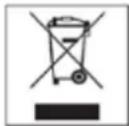
If we decide to not use ever the machine because it is obsolete, damaged or worn, its out of service must be entrusted to specialized and trained personnel. At the end of the dismantling activities all identification plates and other document must be destroyed. The machine can be sold without the possibility to reduce it in small pieces; it is sufficient to disconnect the main groups that compose it and to send them for the scrapping.
Don't sell the machine like mixed urban refusal, perform the waste separation.
The machine collection or harvest systems are:
• Collection through distributor consortium
- Delivery possibility to the machine distributor equivalent to the purchasing certificate of a new machine.
In the machine there aren't dangerous substances with potentially negative effects on the ambient and on the human health. It is fundamental that the purchasers contribute to the reuse, to the recycling and to the other forms of machine restoring. It is the employer obligation to be aware of the actual laws of own country and work so to be comply with these legislations.

It is forbidden and besides liable of penalties to leave the machine and the electric equipment in the ambient.
•
CHAP. 7. MANUFACTURING MATERIALS
In accordance with the functioning and production requirements, the machine can be constituted with different typology of manufacturing materials.
| GROUP | MATERIALS TYPOLOGY | ||||
| Stainless Steel 18/8 | Stainless Steel AISI 304 | Stainless Steel AISI 440 | Cast iron treated for foods | Aluminum treated for foods | |
| Machine body and hopper | ● | ||||
| Knifes and drilled plate | ● | ||||
| Grinding group Enterprise | ● | ● | ● | ||
| Grinding group half Unger | ● | ● | |||
| Grinding group Unger total | ● | ● | |||
| Grinding group T... 12 / T... 22 | ● | ● | ● | ||
| Grinding group T... 32 | ● | ||||
| Grinding group T... 32 ECO | ● | ● | |||
| Grinding group T... 32 R | ● | ||||
CHAP. 8. OPTIONAL
TOMATO MASHER OPTIONAL
The tomato masher is an optional accessory for the set machines 12 and 22. It is able to squeeze tomatoes, fruit (without stone) and vegetable (cooked).
The food product load in the hopper happens manually; always manually and with the pestle help the food product is introduced in the grinding neck towards the Archimedean screw.
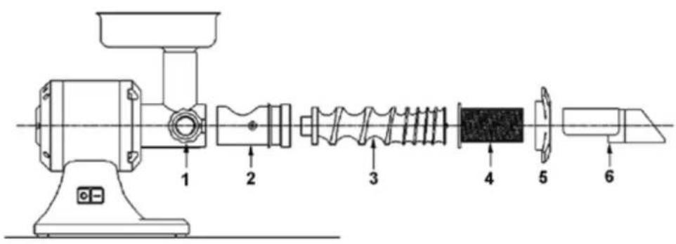
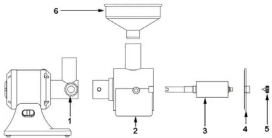
The tomato masher application assembly on the machine is made in the following phases (in exemplification way it is reported the machine with the basic body)
- assemble the pipe union 2 and tighten it with the proper accessories block knob 1
- Insert the Archimedean screw 3 inside the pipe union 2
- Insert the filter 4
- Block the filter with the wheel 5
- Insert and position the drain 6
- Arrange the salvage dump containers for the puree and for the reject
- For the functioning refer to the mincer instruction
PUREE MASHER OPTIONAL
The puree masher is an optional accessory for the set machine 12 and 22. It is able to prepare potatoes or boiled pulses puree. The food product load in the hopper happens manually; always manually and with the pestle help the food product is driven towards the crushing roll.
The puree masher application assembly on the machine is performed in the following phases (in exemplification way it is reported the machine with the basic body).
- Assemble the puree masher body 2 and tighten it with the block accessories knob 1
- Insert the pivot with roll 3 inside the puree masher body 2
- Assemble the closure stopper 4
- Block the closure stopper 4 though two knobs 5
- Insert the hopper 6
- Arrange the salvage dump containers for the vegetable puree
- For the functioning refer to the mincer instructions
INDEX
CHAP. 1. ORGANISATION DU CONTENU ET MODALITES DE CONSULTATION 3
CHAP. 2. INFORMATIONS GENERALES ET CARACTERISTIQUES 4
CHAP. 3. INSTRUCTIONS POUR LA SECURITE 8
CHAP. 4. TRANSPORT, MISE EN ROUTE ET EMPLOI 9
CHAP. 5. ENTRETIEN, RECHERCHE DEFAILLANCES ET NETTOYAGE 14
CHAP. 6. DEMANTELEMENT 17
CHAP. 7. MATERIAUX DE CONSTRUCTION 17
CHAP. 8. OPTIONAL 18
GARANTIE
EMPLOI NORMAL, EMPLOI ABUSIF, EMPLOI NON CORRECT OU INTERDIT
TRANSPORT, MANUTENTION EMMAGASINAGE
OPTIONAL PASSE-PUREE
INHALT
SCHEDE ELETTRONICHE
ELECTRONIC CARDS
FICHAS ELECTRÓNICAS
FICHES ELECTRONIQUES
LEITERPLATTEN
ЭЛЕКТРОННЫЕ СХЕМЫ
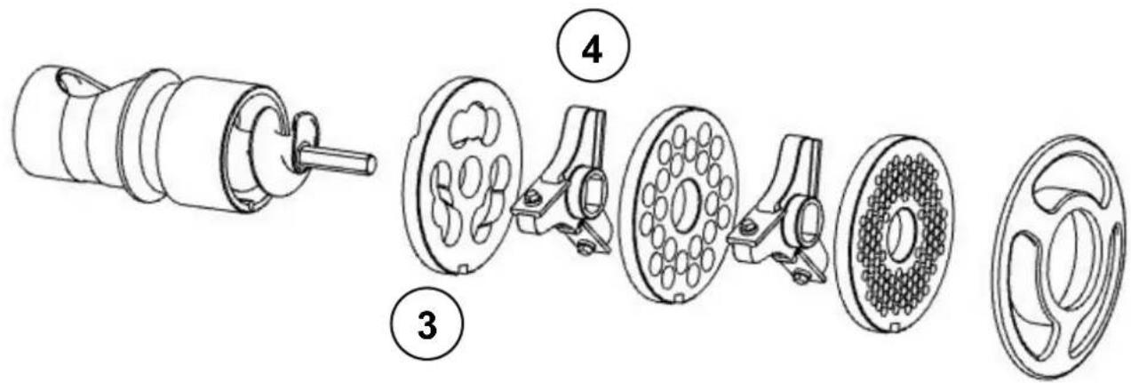
T.. 12 / T.. 22 (1N PE AC 230V 50Hz)
PE = ground conductor
PDC = thermal protection
W1 = bridge
S2 = stop button
S1= start button
F = fuse 500 mA
C = condenser
2-3 = motor
1-4 = 2 AC 230V 50Hz
L1-N1 = motor
L-N=2 AC 230V 50Hz
PE = conductor de tierra
SQL = micro interruptor
S2 = botón de stop
S1= botón de start
F = fusible 500mA
C = condensador
2-3 = motor
1-4=2 AC 230V 50Hz
L1-N1 = motor
L-N=2 AC 230V 50Hz
U - V - W = motore
PE = ground conductor
S1= start button
S2 = stop button
W1 = bridge
PDC = thermal protection
F = fuse 500mA
A = 3 AC 400V 50Hz
1-3 = feeding 400V
1-2 = feeding 230V
B = feeding 400V
C = feeding 230V
U - V - W = motor
PE = conductor de tierra
S1= botón de start
S2 = botón de stop
SQL = micro interruptor
1-3 = alimentation 400V
1-2 = alimentation 230V
B = alimentation 400V
C = alimentation 230V
U - V - W = motor
PE = erdungsleiter
S1= start-taste
S2= stopp-taste
W1 = brücke
PDC = thermoschutzschalter
F = sicherung 500mA
A = 3 AC 400V 50Hz
1-3 = speisung 400V
1-2 = speisung 230V
B = speisung 400V
C = speisung 230V
U - V - W = мотор
PTF04
| T.. 32 (1N PE AC 230V 50Hz) | |
| PE = conduttore di terraA = 2 AC 230V 50HzPDC = protezione termicaW1 = ponteS1= pulsante indictroS2 = pulsante avantiS3 = pulsante stopC = condensatorePE = ground conductorA = 2 AC 230V 50HzPDC = thermal protectionW1 = bridgeS1= back buttonS2 = forward buttonS3 = stop buttonC = condenserPE = conductor de tierraA = 2 AC 230V 50HzPDC = protección térmicaW1 = pucnteS1 = botón atrásS2 = botón adelanteS3 = botón stopC = condensadorPE = conducteur de terreA = 2 AC 230V 50HzPDC = protection termiqueW1 = pontS1= poussoir en arrièreS2 = poussoir en avantS3 = poussoir stopC = condensateurPE = erdungsleiterA = 2 AC 230V 50HzPDC = thermoschutzschalterW1 = brückeS1= taste zurückS2 = taste vorS3 = taste stoppC = kondensatorPE = заземляющий проводA = 2 AC 230V 50HzPDC = термическая защитaW1 = мостS1= кнопка назадS2 = кнопка впередS3 = кнопка стопC = конденсатор | TGM3 230V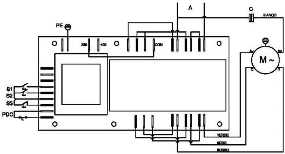 |
ITR-S-2 230V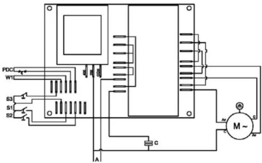 | |
| T..32 (3Ph PE AC 400V 50Hz) | |
| PE = conduttore di terraA = 3 AC 400V 50HzPDC= protezione termicaW1 = ponteS1= pulsante indictroS2 = pulsante avantiS3 = pulsante stopPE = ground conductorA = 3 AC 400V 50HzPDC= thermal protectionW1 = bridgeS1= back buttonS2 = forward buttonS3 = stop buttonPE = conductor de tierraA = 2 AC 230V 50HzPDC= protección térmicaW1 = pucnteS1 = botón atrásS2 = botón adelanteS3 = botón stopPE = conducteur de terreA = 3 AC 400V 50HzPDC= protection thermiqueW1 = pontS1= poussoir en arrièreS2 = poussoir en avantS3 = poussoir stopPE = erdungsleiterA = 3 AC 400V 50HzPDC=thermoschutzschalterW1 = brückeS1= taste zurückS2 = taste vorS3 = taste stoppPE = заземляющий проводA = 3 AC 400V 50HzPDC= термическая защитaW1 = мостS1= кнопка назадS2 = кнопка впередS3 = кнопка стоп | TGM3 400V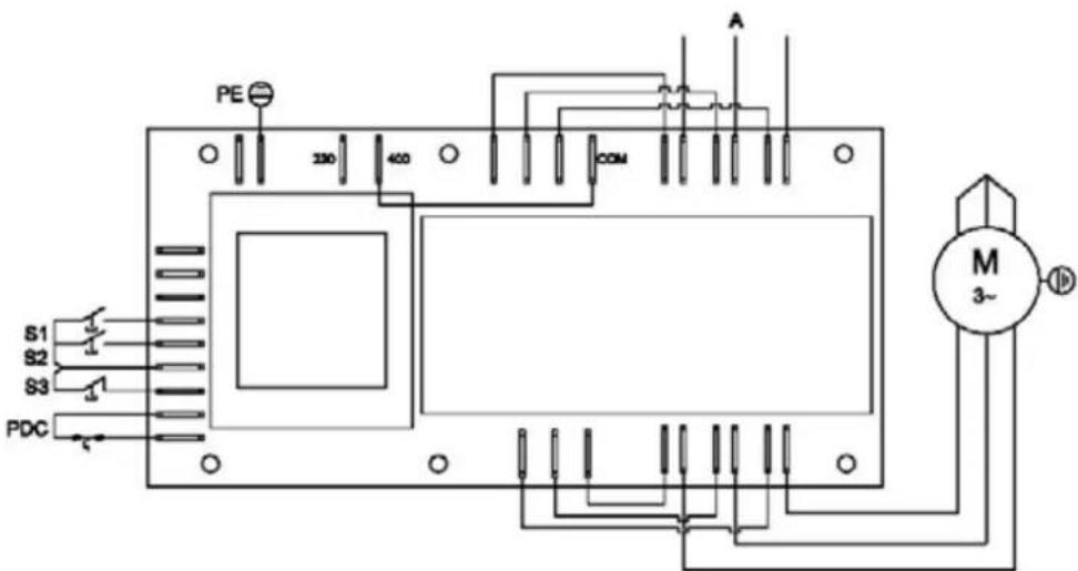 |
ITR-S-2 400V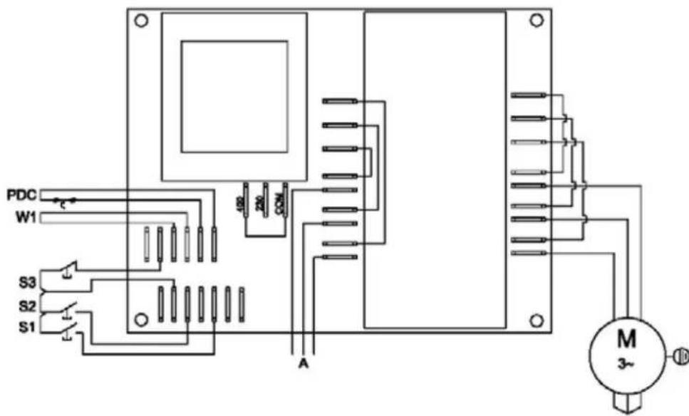 |

- INDEX
- GUARANTEE
- CHAP. 1. CONTENT ORGANIZATION AND CONSULTATION MODALITY
- MANUAL PURPOSE
- MANUAL IMPORTANCE
- SCOPE / MANUAL PURPOSE
- RECEIVERS
- RESPONSIBILITY
- SIMBOLOGY MEANING
- DANGER
- PRECAUTION
- ATTENTION
- CHAP. 2. GENERAL INFORMATION AND CHARACTERISTICS
- USE DESTINATION AND MANUFACTURE PARTS
- NORMAL USE, IMPROPER USE, NOT CORRECT USE OR FORBIDDEN
- CHAP. 3. SAFETY INSTRUCTIONS
- INTRODUCTION
- ENVIRONMENTS, WORKING AND PASSING PLACES
- WARNINGS ON THE RESIDUAL RISKS
- RESIDUAL RISK DUE TO THE FIXED PROTECTIONS REMOVAL, INTERVENTIONS ON BROKEN/WORN
- PARTS
- PROTECTION DEVICES ON THE MACHINE
- CHAP. 4. TRANSPORTATION, PUT ON SERVICE AND USE
- WORKING POSITIONS AND OPERATORS TASKS
- TRANSPORTATION, HANDLING AND STORING
- PACKING REMOVAL – OPENING MODALITY
- PACKING DECRIPION - HOW GET RID OF THE PACKING MATERIAL
- PREPARATION PRELIMINARY OPERATIONS
- STABILITY
- ELECTRIC FEEDING
- ELECTRIC FEEDING SECTIONING DEVICE
- GRINDING GROUP ASSEMBLY / DISASSEMBLY
- GRINDING GROUP ROTATION
- FUNCTIONING DESCRIPTION
- STARTING
- STOP
- FUNCTIONING SAFETY
- VOLTAGE LACKING
- PUT IN FUNCTION
- SWITCHING OFF
- UNBLOCK IN CASE OF OBSTACLE
- CHAP. 5. MAINTENANCE, BREAKS RESEARCH AND CLEANING
- MAINTENANCE MAN REQUIREMENTS
- MAINTENANCE PRESCRIPTIONS
- PROTECTIONS REMOVAL AND/OR PROTECTION DEVICES
- INSULATION FROM THE EXTERNAL FEEDING SOURCES
- BREAKS OR DAMAGES RESEARCH AND MOVING ELEMENTS UNBLOCKING
- CLEANING
- CHAP. 6. SELLING
- CHAP. 7. MANUFACTURING MATERIALS
- CHAP. 8. OPTIONAL
- TOMATO MASHER OPTIONAL
- PUREE MASHER OPTIONAL
- GARANTIE
- EMPLOI NORMAL, EMPLOI ABUSIF, EMPLOI NON CORRECT OU INTERDIT
- TRANSPORT, MANUTENTION EMMAGASINAGE
- OPTIONAL PASSE-PUREE
- INHALT
- SCHEDE ELETTRONICHE
- ELECTRONIC CARDS
- FICHAS ELECTRÓNICAS
- FICHES ELECTRONIQUES
- LEITERPLATTEN
- ЭЛЕКТРОННЫЕ СХЕМЫ
Brand : Fama
Model : 410122
Category : Chopper